JP4597333B2 - Collective power measurement - Google Patents
Collective power measurement Download PDFInfo
- Publication number
- JP4597333B2 JP4597333B2 JP2000253425A JP2000253425A JP4597333B2 JP 4597333 B2 JP4597333 B2 JP 4597333B2 JP 2000253425 A JP2000253425 A JP 2000253425A JP 2000253425 A JP2000253425 A JP 2000253425A JP 4597333 B2 JP4597333 B2 JP 4597333B2
- Authority
- JP
- Japan
- Prior art keywords
- signal
- power level
- power
- signals
- base station
- Prior art date
- Legal status (The legal status is an assumption and is not a legal conclusion. Google has not performed a legal analysis and makes no representation as to the accuracy of the status listed.)
- Expired - Fee Related
Links
Images


Classifications
-
- G—PHYSICS
- G01—MEASURING; TESTING
- G01R—MEASURING ELECTRIC VARIABLES; MEASURING MAGNETIC VARIABLES
- G01R11/00—Electromechanical arrangements for measuring time integral of electric power or current, e.g. of consumption
- G01R11/02—Constructional details
-
- H—ELECTRICITY
- H04—ELECTRIC COMMUNICATION TECHNIQUE
- H04W—WIRELESS COMMUNICATION NETWORKS
- H04W52/00—Power management, e.g. TPC [Transmission Power Control], power saving or power classes
- H04W52/04—TPC
- H04W52/18—TPC being performed according to specific parameters
- H04W52/24—TPC being performed according to specific parameters using SIR [Signal to Interference Ratio] or other wireless path parameters
-
- H—ELECTRICITY
- H04—ELECTRIC COMMUNICATION TECHNIQUE
- H04W—WIRELESS COMMUNICATION NETWORKS
- H04W52/00—Power management, e.g. TPC [Transmission Power Control], power saving or power classes
- H04W52/04—TPC
- H04W52/18—TPC being performed according to specific parameters
- H04W52/26—TPC being performed according to specific parameters using transmission rate or quality of service QoS [Quality of Service]
- H04W52/267—TPC being performed according to specific parameters using transmission rate or quality of service QoS [Quality of Service] taking into account the information rate
-
- H—ELECTRICITY
- H04—ELECTRIC COMMUNICATION TECHNIQUE
- H04W—WIRELESS COMMUNICATION NETWORKS
- H04W52/00—Power management, e.g. TPC [Transmission Power Control], power saving or power classes
- H04W52/04—TPC
- H04W52/30—TPC using constraints in the total amount of available transmission power
- H04W52/34—TPC management, i.e. sharing limited amount of power among users or channels or data types, e.g. cell loading
-
- H—ELECTRICITY
- H04—ELECTRIC COMMUNICATION TECHNIQUE
- H04W—WIRELESS COMMUNICATION NETWORKS
- H04W52/00—Power management, e.g. TPC [Transmission Power Control], power saving or power classes
- H04W52/04—TPC
- H04W52/38—TPC being performed in particular situations
- H04W52/40—TPC being performed in particular situations during macro-diversity or soft handoff
-
- H—ELECTRICITY
- H04—ELECTRIC COMMUNICATION TECHNIQUE
- H04W—WIRELESS COMMUNICATION NETWORKS
- H04W52/00—Power management, e.g. TPC [Transmission Power Control], power saving or power classes
- H04W52/04—TPC
- H04W52/38—TPC being performed in particular situations
- H04W52/50—TPC being performed in particular situations at the moment of starting communication in a multiple access environment
Landscapes
- Engineering & Computer Science (AREA)
- Computer Networks & Wireless Communication (AREA)
- Signal Processing (AREA)
- Physics & Mathematics (AREA)
- General Physics & Mathematics (AREA)
- Mobile Radio Communication Systems (AREA)
- Monitoring And Testing Of Transmission In General (AREA)
- Transmitters (AREA)
Description
【0001】
【発明の属する技術分野】
本発明は、一般的には無線通信システムに関し、特に、無線通信システムにおける電力測定に関する。
【0002】
【従来の技術】
無線通信システムでは多数のシステム・ユーザーが相互に交信できるようにするためにコード分割多重アクセス(“CDMA”)変調技術が用いられている。そうしたシステムの稼動能力は、各信号が偽ランダム・ノイズ(“PN”)シーケンスなどの拡散シーケンスとウォルシュ・コードなどの直交拡散シーケンスによって符号化されるという事実に基づいている。この符号化によって受信装置側での信号分離及び信号再構成が可能になる。これによって、複数の送信信号が同じ帯域幅を共有することが可能になる。特定の送信信号は受信装置側にインプリメントされている拡散シーケンスに関係付けられた知られているユーザー脱拡散シーケンスによってすべての信号からひとつの脱拡散させることで通信チャンネルから検索される。
【0003】
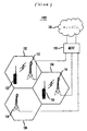
図1はCDMAシステム100を示している。CDMAシステム100によってサービスを提供されている地理的エリアは『セル』とよばれるスペース的に区別された複数のエリアに分割されている。セル102、104、106はハニカム・パターンで六角形で図示されているが、各セルは実際にはそのセルを取り囲む領域の地形に応じて不規則な形状をしている。各セ102、104、及び106はそれぞれひとつの基地局112、114、及び116を含んでいる。各基地局112、114、及び116は移動交換センター(MSC)118と交信するための設備を有しており、これは公衆回線網(PSTN)などの市内あるいは長距離送信ネットワーク120に接続されている。各基地局112、114、及び116はその基地局が移動端末122、124と交信するために用いる無線装置及びアンテナも含んでいる。
【0004】
【発明が解決しようとする課題】
CDMAシステムで通話が設定されると、基地局と移動端末は前方(順方向)リンク及び逆方向リンクを通じて交信する。前方リンクは基地局から移動端末に信号を送信するための通信チャンネルを含んでおり、逆方向リンクの方は上記移動端末から基地局に対して信号を送信するための通信チャンネルを含んでいる。基地局はここでは前方リンク・チャンネルと呼ばれ、先行技術では前方間接チャンネルとして知られている通信チャンネルを通じて移動端末に対して一定のタイプの制御情報を送信する。前方リンク制御チャンネルはパイロット、ページング、及び同期化チャンネルを有している。この基地局は音声又はデータ、あるいはある種の制御情報をここでは前方リンク・トラフィック・チャンネルと呼ばれる通信チャンネルを通じて送信する。通信チャンネル上の信号はここではフレームと呼ばれる期間に組織化されている。フレームは一般的には20ミリ秒の長さである。制御チャンネルを通じて送信される信号はここでは制御信号と呼ばれ、トラフィック・チャンネルを通じて送られる信号はここではトラフィック・チャンネルと呼ばれる。
【0005】
【課題を解決するための手段】
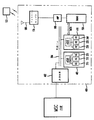
図2は基地局112の一部を示している。基地局112はマスター制御装置130、チャンネル・ユニット140及び142、基本帯域送信及び受信部を含む無線装置150、そしてRF部を含んでいる。基地局112はアンプ160、周辺ハードウエア170、及びアンテナ180を含んでいる。2つのチャンネル・ユニットしか示されていないが、基地局が含むチャンネル・ユニットはそれ以上でも以下でもよい。
【0006】
各チャンネル・ユニット140及び142はそれぞれチャンネル・ユニット制御装置196及び198と多重チャンネル要素184、186,188と190、192、194を有している。チャンネル要素は基地局によって処理される各通話のために必要である。このチャンネル要素は拡散こーどで信号内のデータを符号化する。基地局112によって送信される各信号はそれらのチャンネル要素からのひとつの出力である。これらのチャンネル要素の出力はデジタル的に結合されて、結合帯域信号を形成する。結合帯域信号はその後入力として無線装置150に提供され、そこで、上記信号は多少増幅されて、搬送信号上に変調される。変調された信号はアンプ160によって増幅され、その後、アンテナ180を通じて移動端末122に送信される。
【0007】
基地局112が考慮に入れねばならない資源管理上の問題のひとつは、前方リンク電力をどのように管理するかという問題である。基地局112は追加電力が求められた場合、基地局アンプの最大電力出力が超えられないようにどの程度の電力が送信されているのかを判定しなければならない。
【0008】
【発明の実施の形態】
基地局112はほとんどの基地局でインプリメントされる各トラフィック信号の対する個別電力信号と、いくつかの基地局でインプリメントされる過負荷電力制御の2つの形態の電力制御をインプリメントできる。
【0009】
個別電源制御の場合、基地局112はその基地局と交信している他の移動端末の前方(順方向)リンク信号の電力レベルとは無関係な各移動端末に対する前方リンクの電力レベルを判定する。各移動端末は送信された信号を受信して、その移動端末にあてられた前方リンク信号を入手する。移動端末122がトラフィック信号を受信した場合は、IS−95標準に合致したCDMAシステムにおいては、移動端末122は受信された前方リンク・トラフィック・フレームがエラーかどうかを判定する。移動端末122が送信する後の逆方向リンク・トラフィック・フレームにおいて、移動端末122はエラーかどうかを基地局112に知らせる。CDMA2000システムで、移動端末122は、通常はその前方リンク・トラフィック信号の信号対ノイズ比率をチェックすることで、受信された前方リンク・トラフィック信号がシステム内のノイズを克服するのに十分な信号強度を持っているかどうかを判定する。移動端末122はその後、前方リンク・トラフィック信号強度が十分かどうかを基地局112に示す。
【0010】
(IS−95準拠システムで)エラーがあったかどうか、あるいは(CDMA2000システムで)前方リンク・トラフィック信号の強度が十分であるかどうかの情報を移動端末122から受信したら、基地局112はこの移動端末に対する前方リンクがフェードしているかどうかについて判断する。基地局112はその後、その信号の電力レベルを調整する。たとえば、基地局112がエラーの前方リンク・トラフィック・フレームがあるという示唆を1回以上受信した場合には、基地局112はこの前方リンク・トラフィック・チャンネルがフェードしつつあると判定して、この信号の電力レベルを増大させる。
【0011】
過負荷電力制御の目的は、基地局112によって送られる集合電力がその基地局の設備が一定の期間作動するように指定されている電力レベルを超えないようにすることである。過負荷電力制御は、基地局によって同時に送信できる信号の数がすべての送信信号の集合電力によって制限されるような場合に利点がある。送信されるすべての信号の集合電力は、アンプ60が一定期間に作動することが指定されている最大出力電力レベルがあるので、同時に送信することができる信号の数に対する制限的な要因である。この最大出力電力はここではそのアンプの最大継続電力レベルを称する。電力レベルがアンプの最大継続電力レベルに達すると、過負荷状態が発生する。基地局は追加電力が求められた場合にアンプの最大継続電力レベルが超えられないように、どの程度の集合電力が送られているのかについて判断しなければならない。
【0012】
何らかの形状の過負荷制御機能を有している通常のCDMAシステムでも、過負荷状況になってしまうという問題を解決できないでいる。過負荷制御は基地局112が個々のトラフィック・チャンネルの電力要求の急速な変化と過負荷電力制御を行うために用いられるフィードバックが比較的遅いことから過負荷状態になってしまうことを阻止することができない。マスター制御装置130は一般的にはアンプ160によって増幅される信号の集合電力レベルを得て、過負荷状態が発生しているかどうかについて判定する。
【0013】
マスター制御装置130はチャンネル・ユニット140及び142から各信号の電力レベルを得ることで、集合電力レベルを知る。チャンネル・ユニット140及び142は各信号のゲインと情報量を用いてその信号の電力レベルを得る。各チャンネル・ユニット140及び142はその制御下にある各チャンネル要素からその信号のゲイン及び情報量を受け取る。チャンネル・ユニット140及び142は、1)そのチャンネル要素に対応する信号のゲインに変化があるか、あるいは2)一定時間、例えば1秒間、ゲインに変化があった場合に、そのゲイン及び情報量を受け取る。情報量とは1秒あたりに送信される情報のビット数であるフル・レート、1/2レート、1/4レート及び1/8レートの4つのことなった情報量(情報速度)があり得る。大量の情報が基地局から移動端末に送られる時に情報量はフル・レートであり、少量の情報が基地局から移動端末に送信されている時は1/8レートである。1/2及び1/4レートは過渡的なレートである。前方リンクでは、情報量が1/2、1/4または1/8の場合、各フレーム内で送信されている音声及びデータ・ビットの設定数であるチャンネル量は情報量より高く、その情報は1フレームあたり数回反復される。
【0014】
各チャンネル要素に対して、チャンネル・ユニット140及び142は一定期間の情報量を平均して、その平均情報量を最後に報告されたゲインの平方を掛けてチャンネル要素に関連した信号の電力レベルを得る。各チャンネル・ユニット140及び142はその後、その電力レベルをマスター制御装置130に送り、そしてマスター制御装置130はそれと交信している各チャンネル要素での電力レベルを合計して集合電力レベルを得る。マスター制御装置130はその集合電力レベルをアンプの最大係属電力レベルと比較して、過負荷状態が起きているかどうかを判定する。マスター制御装置130が過負荷状態であると判定した場合は、基地局はいくつかの対応策のひとつを実行する。この対応策は、通常、a)ここでは通話ブロッキングと呼ばれるすべての新しい通話要求に対するアクセスの否定、b)送信信号の現在レベルへの限定、あるいはc)送信信号の間引き、などである。
【0015】
上に述べたように、チャンネル・ユニット制御装置140及び142が所定の一定期間、通常は数秒間での情報量を平均化することから問題が発生する。ゲインはこの所定の一定期間中に数回変化しているかもしれない。従って、チャンネル・ユニット制御装置140及び143によって得られる電力レベルはそれらの信号の実際の電力とは異なっているかもしれない。マスター制御装置130はこれらの電力レベルを用いてそれらの信号の集合電力レベルを得るので、このようにして得られた集合電力レベルは基地局112によって送信される電力レベルではないかもしれない。しかしながら、マスター制御装置130が過負荷状態が発生しているかどうかを判定するためにアンプの最大継続電力レベルを比較するのはこのようにして得られた集合電力レベルなのである。従って、マスター制御装置130はいつ過負荷状態が発生したのかを正確に判定できない可能性がある。その結果、通常の基地局はアンプ160の最大継続電力レベルを上回ってしまい、それによってアンプ160を壊してしまう可能性もある。こうした従来の基地局の欠陥はそうした過負荷状態に対応するために、過剰な設計上の配慮を必要とさせていた。アンプ上の過剰なマージンより高価で大規模なシステムを必要とさせているが、それでも基地局に過負荷状態が発生しないことは保証できていないのである。
【0016】
本発明は1つの測定期間中に1つの基地局の少なくとも1つの前方リンク信号の電力レベルを判定することで上に述べた問題を解決し、この場合、上記特定間隔は少なくとも1つの電力指示信号特性が変化できる期間より短いか、あるいはそれと等しくなっている。電力指示信号特性とは、例えば、その信号の情報量である。情報量は1フレームにつき1回変化する場合は、その測定期間は1フレームより短いか、あるいはそれと等しくなっている。その測定期間はいずれかの電力指示信号特性が変化できる期間より短い方が好ましい。この測定期間は固定長あるいは可変長のいずれでもよい。
【0017】
信号の電力レベルはその測定期間中のその信号の電力指示信号特性に基づくものである。本発明のひとつの実施の形態で、信号の電力指示信号特性はその信号の情報量とゲインを含んでいる。電力指示信号特性は1つのトラフィック信号内に含まれている情報が制御信号化あるいは音声及び/又はデータ情報出るかについての情報、その信号が通話を設定するためのものか、あるいは確立された通話の一部かについての情報、及びその通話がソフト・ハンドオフされているかどうかについての情報を含むことができる。
【0018】
前方リンク信号は1つの信号セットの一部である。この信号セットはその基地局を含んでいるセルの1つのセクターに対応するすべての信号か、そのセルの上記セクターに対する信号の一部か、基地局のアンプによって増幅されたすべての信号か、あるいは基地局のアンプによって増幅される信号の一部を含むことができる。例えば、そのセットは複数のトラフィック信号、あるいは複数のトラフィック信号及び1つ又は複数の制御信号を含むことができる。
【0019】
マスター制御装置は複数のチャンネル・ユニットを制御し、各チャンネル・ユニットは複数のチャンネル要素を制御し、各チャンネル要素では各前方リンク信号が1つの制御要素と対応している。本発明のひとつの実施の形態で、各チャンネル・ユニット制御装置は、1)信号セット内にあり、2)そのチャンネル・ユニットに制御されるチャンネル要素に対応している、という両方の条件を満たす各信号の電力レベルを判定する。このチャンネル・ユニットはその後その電力レベルをマスター制御装置に送る。マスター装置はチャンネル・ユニットから受信される電力レベルを合計する。マスター制御装置はこの合計をその信号セット内の信号に対応するチャンネル要素を制御する他のすべてのマスター制御装置に送る。各マスター制御装置はこれらの合計をさらに加算してその信号セットの電力レベルを得る。本発明の他の実施の形態では、各信号の電力レベルを判定するのはマスター制御装置であって、チャンネル・ユニットではない。マスター制御装置は、1)その信号セットにあり、2)そのマスター制御装置によって制御されるチャンネル要素に対応している、という両方の条件を満たす各信号の電力レベルを判定する。
【0020】
少なくとも1つの電力指示信号特性が変化し得る期間より短いか、あるいは等しい継続時間を有する測定期間中に基地局の少なくとも1つの前方リンク信号の電力レベルを判定することは基地局が1つの信号セットの電力レベルをより正確に判定することができるようにする。これはさらに、パイロット・フラクションなどの測定、あるいは過負荷条件など信号セットの電力レベルの知識を必要とする過負荷状態などの状況をより正確に判定することが可能になる。例えば、これによって基地局は過負荷状態をより良く検出して、アンプを保護することが可能になる。
【0021】
図3はCDMAシステムにおける基地局200の一部を示している。本発明のこの実施の形態はCDMAシステムを使った形態で図示されているが、本発明はCDMAシステムの使用に限定されるものではない。本発明はまた、時間分割多重アクセス(TDMA)システム、及びグローバル・システム・フォア・モービル(GSM)システム、あるいは他のいずれの無線通信システムのいずれに対しても同様に適用することができる。
【0022】
基地局200はマスター制御装置202、チャンネル・ユニット205と210、基本帯域送受信部を含む無線装置150、及びRF部を含んでいる。基地局200はさらにアンプ160、周辺ハードウエア170、及びアンテナ180も含んでいる。この図には2つのチャンネル・ユニットしか示されていないが、基地局に含まれるチャンネル・ユニットの数はこれより多くても少なくてもよい。
【0023】
マスター制御装置202は制御バス204によってチャンネル・ユニット205及び210に接続されている。各チャンネル・ユニット205及び210はそれぞれチャンネル・ユニット制御装置250及び255と、多重チャンネル要素215、220、225と230、235、240を含んでいる。チャンネル要素はその基地局によって取り扱われている各通話のために必要である。チャンネル要素は信号内のデータを拡散コードで符号化する。基本局200によって送信される各信号はチャンネル要素215、220、225、230、235及び240の1つからの出力である。各チャンネル・ユニットには3つのチャンネルしか示していないが、各チャンネル・ユニットに含まれるチャンネルの数はこれより多くても少なくても構わない。これらのチャンネル要素の出力はデジタル的に組み合わされて結合基本帯域信号を形成する。この結合基本帯域信号はその後無線装置150に入力されて、そこで信号は多少増幅され、搬送信号に変調される。
変調された信号はアンプ160によって増幅され、その後、アンテナ180を介して移動端末122に送信される。
【0024】
トラフィック信号を移動端末122に送信する場合、このトラフィック信号は市内及び/又は長距離送信ネットワーク120と無線ネットワークのいずれかを介して発信端末からMSC118に送られる。MSC118はそのトラフィック信号をマスター制御装置202に送り、このマスター装置202はそのトラフィック信号を、その信号を処理するチャンネル要素を制御しているチャンネル・ユニット制御装置にバス204を介して送る。例えば、信号がチャンネル要素215によって処理される場合は、マスター制御装置202はその信号をチャンネル・ユニット制御装置250に送る。チャンネル・ユニット制御装置250は1つの測定期間中のその信号の電力指示信号特性のほとんどを判定して、そのトラフィック信号をチャンネル要素215に送る。その信号の個別電力制御によって判定されるゲインなどの電力指示信号特性の一部はチャンネル要素によって設定される。チャンネル・ユニット制御装置250は各測定期間中に少なくとも1回チャンネル要素215からこれらの電力指示信号特性を受け取る。電力指示信号特性はトラフィック信号の情報やその信号のゲインを含む。電力指示信号特性は又その信号に含まれている情報が制御信号であるか、あるいは音声及び/又はデータ情報であるか、トラフィック信号が通話を設定するためにものかあるいは確立された通話のものか、そして通話がソフト・ハンドオフ状態かどうかについての情報を含むこともできる。電力指示信号特性が以下により詳細に説明するような一定の条件を示唆する場合にその信号の電力レベルを調節できるようにするために、スケーリング係数及びゲインはそれら電力指示信号特性と組み合わされている。チャンネル・ユニット制御装置250はゲイン及びスケーリング係数を用いて、その測定期間中のトラフィック信号の電力レベルP[n]を判定する。測定期間は、少なくとも1つの電力指示信号特性が変化し得る期間より短いか、あるいはそれと等しい継続時間を有している。例えば、トラフィック信号の情報量は電力指示信号特性のひとつであり、情報量は1フレーム毎に変化する可能性があるので、従って、測定期間は1フレームである場合もあれば、1つ又は複数の電力制御グループであり、この場合、1つの電力制御グループとは1フレームの1/16である。この測定期間は固定長又は可変長のいずれでもよい。
【0025】
本発明の別の実施の形態で、測定期間はいずれかの電力指示電力特性が変化し得る期間より短くなっている。一般的には、前方リンクで、ゲインは最も急速に変化し得る電力指示信号特性である。基地局が1フレームあたりの電力制御情報を得るIS−95A又はIS−95BなどのCDMAシステムでは、ゲインはフレーム毎に変化する場合があり、従って、測定期間は1フレームと同じか、あるいはそれ以下とされるであろう。CDMA2000システムなどの、基地局が電力制御あたり1回電力情報を得るようなCDMAシステムにおいては、ゲインは1つの電力制御グループあたり1回変化する場合がある。従ってこの場合は、測定期間は1電力制御グループと等しいか、あるいはそれ以下になるであろう。
【0026】
式1に示すように、測定期間中のトラフィック信号の電力レベルP[n]は1)非電力制御シンボルと非電力制御シンボル・フラクションを掛け合わせて得られる電力レベルと、2)電力制御シンボルと電力制御シンボル・フラクションを掛け合わせて得られる電力レベル、とを合計したものである。ここで非電力制御シンボル・フラクションとは測定期間中の総シンボル数(NOS +NPCS )に対する非電力制御シンボル数NOS の比率を示している。電力制御シンボル・フラクションは総シンボル数(NOS +NPCS )に対する電力制御シンボル数NPCS の比率を示しており、電力制御シンボルNPCS は電力制御ビットを示すために用いられるシンボルである。電力制御ビットは移動端末122に対して送信信号の電力レベルを上昇させるか低下させるかを示すビットのことである。
【数1】

チャンネル・ユニット制御装置250は以下のような方法で非電力制御シンボルの電力レベルを得ることができる。チャンネル・ユニット制御装置250は非電力制御シンボルの電力レベルを示し、ここでは非電力制御シンボル・ゲインと賞するゲインGSとGとを平方し、それぞれを掛け合わせて計算された電力レベルを得る。非電力制御ゲインはトラフィック信号に含まれている情報が制御情報か音声及び/又はデータのいずれであるか、及びその信号の個別電力制御によって決められるトラフィック信号のゲインGに基づくゲインGsを含んでいる。トラフィック信号に含まれる情報が制御情報である場合は、Gsは1から2の間の範囲のいずれかの値をとり、そしてそのトラフィック信号に含まれている情報が音声及び/又はデータである場合は、Gsは1と等しい。さらに、信号の個別電力レベルが測定される場合は、スケーリング・ゲインも平方され、Cs 2*G2と掛け合わせて、電力レベルを得る。例えば、信号は以下に詳細に述べる本出願人による米国特許出願第09/356825(又は欧州特許出願公開第1071226号)の『集合過負荷電力制御』に開示されている過負荷電力制御方法の一部として測定することができる。信号の個別電力レベルをスケールする場合は、その測定はそのスケーリング・ゲインを上記個別電力制御によって判定されるゲインGと掛け合わせ、そして、測定されたゲインを平方して、それをCs 2と掛け合わせて、電力レベルを得る。
【0028】
この計算された電力レベル(Cs 2*G2)を最大許容電力レベルLG2 及び最大許容電力レベルMG2 と比較する。最大関数の方は計算された電力レベルを最小許容電力レベルLG2 と比較し、上記2つの値のうちの大きな方を選び、最小関数の方は計算された電力レベルを最大許容電力レベルMG2 と比較して、これら2つの値のうちの小さな方を選ぶ。最小許容電力レベルLG2 は基地局200を含むシステムが準拠している標準によって指定されるような非電力シンボルに対する最低許容電力レベルである。最大許容MG2 電力レベルは前方リンク上でトラフィック信号を送信するが有利である最大電力レベルである。一般的に、最大許容電力レベルMG2 はパイロット信号が送信される電力レベルの50%から80%の範囲で選択することができるが、パイロット信号が送信される電力レベルの50%から100%の範囲で選択することも可能である。最大許容電力レベルMG2 が低い方がキャパシティの改善につながるが、前方リンク・カバリッジは低下する。
【0029】
計算された電力レベル(Cs 2*G2)が最大MG2 及び最小LG2 との間であれば、計算された電力レベル(Cs 2*G2)が非電力制御シンボルのスケーリング係数と掛け合わされて、非電力制御シンボルの電力レベルを得る。非電力制御シンボルのスケーリング係数はトラフィック信号の情報量に基づくスケーリング係数Kr を含んでいる。さらに、信号がトラフィック信号が通話やデータ送信を設定するためのものか、あるいは確立された通話やデータ送信内にあるのかについての情報に基づいて測定される場合は、非電力制御シンボルのスケーリング係数はスケーリング係数Kx を含んでいる。
Krはフル・レート・フレームの場合1、1/2レート・フレームの場合0.5、1/4レート・フレームの場合0.25、そして1/8レート・フレームの場合0.125にそれぞれ等しい。Kx はその基地局のボコーダー・レートである。8Kボコーダーの場合、Kx は1と等しく設定され、変化しない。13Kボコーダーの場合、Kx はそのトラフィック信号が通話やデータ送信を設定するためのものか、あるいはすでに確立された通話やデータ送信の一部であるかに関する情報に基づく。例えば、そのトラフィック信号が通話を設定するためのものであれば、Kx は1と等しく、トラフィック信号が確立された通話の一部であれば、
Kx はフル・レートに対しては1に等しく、そして情報量が1以下であれば
Kx は1−0.25の範囲で変化する。
【0030】
計算された電力レベル(Cs 2*G2)が最大許容電力レベルMG2より上の場合は、最大許容電力レベルMG2は非電力制御信号スケーリング係数(Kr及びKx )と掛け合わされて非電力制御シンボルの電力レベルを得る。計算された電力レベルが最低許容電力レベルLG2 以下であり、最低許容電力レベルLG2 が非電力制御信号スケーリング係数(Kr及びKx )と掛け合わされて非電力制御シンボルの電力レベルを得る。チャンネル・ユニット制御総氏250は非電力制御シンボルを非電力制御シンボル・フラクションNOS /(NOS +NPCS )とを掛け合わせる。
【0031】
チャンネル・ユニット制御装置250は以下の方法で電力制御シンボルの電力レベルを得ることができる。チャンネル・ユニット制御装置250は電力制御シンボルの電力レベルを示し、ここでは電力制御ゲインと賞されるゲインGp及びGをそれぞれ平方して掛け合わせて、計算された電力レベルを得る。電力制御シンボル・ゲインは通話がソフト・ハンドオフ状態であるかどうかに基づくゲインGpと、その信号の個別電力制御によって判定されたトラフィック信号のゲインGを含んでいる。通話がソフト・ハンドオフ、シンプレックス・モードでない場合は、Gpは1と等しく、通話がツー・ウェイ・ソフト・ハンドオフの場合はGpは1.5と等しく、そして通話がスリー・ウェイ・ソフト・ハンドオフあるいはそれ以上であれば、Gpは1.75と等しい。さらに、上に述べたように、信号の個別電力レベルが測定される場合は、スケーリング・ゲインも計算された電力レベルを得る場合に用いられる。この電力レベル(Gp 2 は最大許容電力レベルMG2と比較され、それら2つのうちの小さな方を電力制御シンボル・フラクションNOS /(NOS +NPCS )と掛け合わせられる。
【0032】
チャンネル・ユニット制御装置250は1)非電力制御シンボルと非電力シンボル・フラクションを掛け合わせた電力レベルと2)電力制御シンボルと電力制御シンボル・フラクションとを掛け合わせた電力レベルを合計して測定期間の電力レベルP[n]を得る。
【0033】
チャンネル・ユニット制御装置250はその後電力レベルP[n]をマスター制御装置202を送る。共にその信号セット内にあってそのチャンネル・ユニット250及び255によってそれぞれ制御されているチャンネル要素215、220、225及び230、235、240に対応しているチャンネル・ユニット制御装置250及び255は各トラフィック信号の電力レベルP[n]についての判定を行う。チャンネル・ユニット制御装置250及び255はその後その電力レベルをマスター制御装置202に送る。マスター制御装置202はチャンネル・ユニット250及び255によって送られてくる信号セット内のトラフィック信号の電力レベルを合計する。信号セットが制御信号を含んでいる場合、マスター制御装置202はトラフィック信号の電力レベルの合計に制御信号の電力レベルも加える。制御信号の情報量は通常はフル・レートであるから制御信号の電力レベルは通常は制御信号のゲインの平方である。
【0034】
本発明のひとつの実施の形態では、マスター制御装置202はその後この総計をその信号セット内の信号に対応するチャンネル要素を制御しているすべてのマスター制御装置にこの総計を送る。各マスター制御装置がマスター制御装置と同じ方法でこの総計を判定するようにしてもよいし、別の方法でこの総計を得るようにしてもよい。各マスター制御装置はこれらの総計をさらに合計してその測定期間中の上記信号セットの電力レベルP[n]を得る。この信号セットは、その基地局を含んでいるセルの1つのセクターに対応するすべての信号、あるいはそのセルの1つのセクターに対応する信号の一部、あるいはその基地局のアンプによって増幅される信号のすべて、あるいはその基地局のアンプによって増幅される信号の一部を含むことができる。例えば、そのセットは複数のトラフィック信号、あるいは複数のトラフィック信号と1つ又は複数の制御信号を含むこともできる。
【0035】
本発明の別の実施の形態で、マスター制御装置202は複数の測定期間における信号セットの電力レベルを平均化する。マスター制御装置202はその信号セットの電力レベルを平均するために、単極無限インパルス応答(IIR)フィルターや有限インパルス応答(FIR)フィルターなどのフィルターを用いることができる。測定期間の数はできるだけ正確に1つの測定期間の電力レベルを得ようという希望と、滑らかに変化する電力レベルを得たいという希望とのバランスを取るように選択される。例えば、測定期間の数は5ms−400ms平均化期間を発生させるのに十分なように設定することができる。その場合、マスター制御装置202はこの総計をその信号セット内の信号に対応するチャンネル要素を制御するすべてのマスター制御装置にその合計を送る。各マスター制御装置はこれらの合計をさらに合計してその信号セットの電力レベルP[n]を得る。
【0036】
オプションとして、送信パスの実際のパス・ゲインがその送信パスの通常のパス・ゲインとは違っている場合もあるという事実を考慮に入れて電力レベルPS[n]を調整することもできる。この事実を考慮に入れるために、電力レベルPS[n]を通常のパス・ゲインに対する実際のパス・ゲインの比率と掛け合わせることができる。送信パスのパス・ゲインは基地局200内の送信パスに沿った装置のパス・ゲインである。通常のパス・ゲインはその基地局が通常の状態で較正される時に判定される。この通常のパス・ゲインは送信パスの始点、つまりチャンネル要素で信号の電力レベルを測定し、そしてこの信号の電力レベルをその送信パスの終点で、つまりアンテナで測定するなどのいずれの方法によってでも判定することができる。送信パスの始点での電力レベルに対する同じ送信パスの終点での電力レベルの比率が通常のパス・ゲインである。実際のパス・ゲインは作動中の条件下で判定される。実際のパス・ゲインは送信パスの始点、つまりチャンネル要素で信号の電力レベルを測定し、そしてこの信号の電力レベルをその送信パスの終点で、つまりアンテナで測定するなどのいずれの方法によってでも判定できる。送信パスの始点における電力レベルに対するその送信パスの終点における電力レベルの比率が実際のパス・ゲインである。
【0037】
図4に示す本発明の別の実施の形態で、マスター制御装置402は測定期間中の電力指示信号特性のほとんどを判定し、そしてトラフィック信号をチャンネル要素に送る。その信号の個別電力制御によって判定されるゲインなど、電力指示信号特性の一部はチャンネル要素によって設定される。チャンネル要素はこれらの電力指示信号特性を各測定期間に1回づつマスター制御装置402に送る。マスター制御装置402はこれらのゲインとスケーリング係数を用いて、チャンネル・ユニット制御装置がこの情報を用いて電力レベルP[n]を判定するの同じ方法でその測定期間の信号の電力レベルP[n]を判定する。そして、マスター制御装置402はそのマスター制御装置によって制御されるチャンネル要素に対応する信号セット内の各トラフィック信号の電力レベルを合計する。信号セットが制御信号を含んでいる場合は、マスター制御装置402はそれら制御信号の電力レベルもトラフィック信号の電力レベルの合計に加える。この実施の形態では、チャンネル・ユニット405と410はチャンネル・ユニット制御装置450と455を含まなくてもよいが、その場合、マスター制御装置402がそれらのチャンネル要素を直接制御する。
【0038】
本発明のひとつの実施の形態で、マスター制御装置402はその後この合計を信号セット内の信号に対応するチャンネル要素を制御するすべてのマスター制御装置に送る。各マスター制御装置はこの合計をマスター制御装置402と同様に判定することもできるし、あるいは他のいずれの方法でこの合計を得ても構わない。各マスター制御装置はこれらの合計をさらに総計して、その測定期間の信号セットの電力レベルPS[n]を得る。
【0039】
本発明の別の実施の形態で、マスター制御装置402は複数の信号間隔における信号の電力レベルを平均化する。測定期間の数は1つの測定期間における電力レベルをできるだけ正確に得ようとする希望と、滑らかに変化する電力レベルを得ようとする希望との間のバランスを図るように選択される。例えば、測定期間の数は5ms−400ms平均化期間を発生させるのに十分なように設定することができる。そして、マスター制御装置402はこの合計をその信号セット内の信号に対応するチャンネル要素を制御しているすべてのマスター制御装置に送る。
【0040】
オプションとして、 オプションとして、送信パスの実際のパス・ゲインがその送信パスの通常のパス・ゲインとは違っている場合もあるという事実を考慮に入れて電力レベルPS[n]を調整することもできる。この事実を考慮に入れるために、上に述べたように、電力レベルPS[n]を通常のパス・ゲインに対する実際のパス・ゲインの比率と掛け合わせることができる。
【0041】
1つの測定期間における前方リンク信号の電力レベルを判定する方法は過負荷制御のための方法と組み合わせて用いることができる。例えば、この方法は、参照によって本明細書に組み込まれる本出願人による米国特許出願第09/356825(又は欧州特許出願公開第1071226号)の『集合過負荷電力制御』に開示されている過負荷電力制御方法と組み合わせて用いることができる。この過負荷電力制御方法はその信号セットにおける前方リンク信号のそれぞれの個別電力制御とは無関係に、アンプの最大継続電力レベルに基づく閾値電力に応じて1つのセットの前方リンク信号の電力レベルを変化させる。この信号セットの電力レベルはスケーリング係数によってそれをスケールすることによって変換させる。信号セットの総電力レベルは現期間中に得られ、そしてその後の期間で用いられるスケーリング係数が決められる。このスケーリング係数は好ましくは現期間中の信号セットの総電力、現期間中に用いられるスケーリング係数、それに閾値電力レベルに基づいている。
総電力レベルがアンプの最大継続電力レベルを超える量が過負荷量である。スケーリング係数は各期間毎に過負荷量が固定係数のパーセンテージによって減少される。例えば、過負荷量は現期間中に3%減らし、その後の期間で過負荷量が減少されるパーセンテージは現期間中のスケーリング係数とその後の期間の過負荷量に基づいて設定される。
【0042】
さらに、1つの測定期間の前方リンク信号の電力レベルを判定する上記方法を参によって本明細書に組み込まれる本出願人による米国特許出願第09/356816号(米国特許第6487415号)の『コール・ブロッキングを利用した過負荷制御』に開示されているコール・ブロッキングと組み合わせて用いることができる。この方法は前方リンクの通話品質測定に対応してコール・ブロッキングを開始する。通話品質測定は、移動端末がどの程度よく前方リンクから受信できるかについての測定である。例えば、1つの通話品質測定は電力フラクションで、これは本発明においてより正確に得ることができる。
【0043】
上に述べたことは単に例示を目的とするものである。従って、例えば例示的な実施の形態においては、非電力制御シンボルの電力レベルを判定する多数の電力指示信号特性が用いられている。別の実施の形態では、情報量と信号の個別電力制御によって判定されるゲインだけを非電力制御シンボルに関する電力レベルを判定する用いることができる。さらに、電力制御シンボルの電力レベルは上に述べたのと同じ方法で判定することができ、あるいは信号の個別電力制御によって判定されるゲインだけを用いて判定することもできる。
【0044】
さらに、上記の例示的な実施の形態においては、トラフィック信号の電力レベルだけが電力指示信号特性を用いて判定されているが、別の実施の形態では、トラフィック信号と制御信号の両方をその信号の電力指示信号特性を用いて判定することができる。
【0045】
さらに、上記の例示的な実施の形態においては、基地局が1つのアンプを含んでいるが、別の実施の形態においては、基地局は複数のアンプを含んでおり、各アンプが信号セットを増幅する。この場合、各信号セットの電力レベルは上のプロセスを用いて判定することができる。さらに、当業者であれば、例示的な実施の形態においては各セルが全セクター・セルであるのに対して、上記セルを複数のセクターに分割して、各セクターが独自のチャンネル要素、無線装置、アンプ、及びアンテナを持つようにしてもよいことは容易に理解するであろう。この場合、各セクターに関連した信号セットの電力レベルを上記のプロセスを用いて判定することができる。
【0046】
本発明を好ましい実施の形態を参照して上にのべたが、上記明細書及び図面を参照した当業者であれば、本発明の精神と範囲を逸脱せずに種々の修正や変更が可能であることは容易に理解できるであろう。
【図面の簡単な説明】
【図1】無線通信システムの一部の構成図。
【図2】通常の基地局の一部を含む上記無線通信システムの同じ一部の構成図。
【図3】チャンネル・ユニット及びマスター制御装置が共に1つの信号セットの電力レベルを得る基地局の一部分を含む上記通信システムの同じ部分の構成図。
【図4】上記マスター制御装置が1つの信号セットの電力レベルを得る基地局の一部を含む無線通信システムの同じ部分の構成図。[0001]
BACKGROUND OF THE INVENTION
The present invention relates generally to wireless communication systems, and more particularly to power measurement in wireless communication systems.
[0002]
[Prior art]
In wireless communication systems, code division multiple access ("CDMA") modulation techniques are used to allow multiple system users to communicate with each other. The operational capability of such a system is based on the fact that each signal is encoded by a spreading sequence such as a pseudo-random noise (“PN”) sequence and an orthogonal spreading sequence such as a Walsh code. This encoding enables signal separation and signal reconstruction on the receiving device side. This allows multiple transmission signals to share the same bandwidth. A particular transmitted signal is retrieved from the communication channel by despreading all signals one by a known user despreading sequence associated with the spreading sequence implemented on the receiver side.
[0003]
FIG. 1 shows a
[0004]
[Problems to be solved by the invention]
When a call is set up in the CDMA system, the base station and the mobile terminal(Forward direction)Communicate over links and reverse links. The forward link includes a communication channel for transmitting a signal from the base station to the mobile terminal, and the reverse link includes a communication channel for transmitting a signal from the mobile terminal to the base station. The base station is referred to herein as the forward link channel and transmits certain types of control information to the mobile terminal through a communication channel known in the prior art as a forward indirect channel. Forward linkcontrolChannels include pilot, paging, and synchronization channels. This base station transmits voice or data, or some kind of control information, through a communication channel, here called the forward link traffic channel. The signals on the communication channel are organized here in a period called a frame. The frame is typically 20 milliseconds long. The signal transmitted through the control channel is referred to herein as the control signal, and the signal sent through the traffic channel is referred to herein as the traffic channel.
[0005]
[Means for Solving the Problems]
FIG. 2 shows a part of the
[0006]
Each
[0007]
One of the resource management issues that the
[0008]
DETAILED DESCRIPTION OF THE INVENTION
[0009]
In the case of individual power control, the
[0010]
Upon receiving information from the
[0011]
The purpose of overload power control is to ensure that the aggregate power sent by the
[0012]
Even a normal CDMA system having some form of overload control function cannot solve the problem of an overload situation. Overload control prevents the
[0013]
The
[0014]
For each channel element,
[0015]
As noted above, problems arise because the
[0016]
The present invention solves the above mentioned problem by determining the power level of at least one forward link signal of one base station during one measurement period, in which case the specific interval is at least one power indication signal. It is shorter than or equal to the period during which the characteristic can change. The power instruction signal characteristic is, for example, the amount of information of the signal. When the amount of information changes once per frame, the measurement period is shorter than or equal to one frame. The measurement period is preferably shorter than the period during which any of the power instruction signal characteristics can be changed. This measurement period may be fixed length or variable length.
[0017]
The power level of the signal is based on the power indication signal characteristics of the signal during the measurement period. In one embodiment of the present invention, the power indication signal characteristic of the signal includes the information amount and gain of the signal. The power indication signal characteristics are information about whether information contained in one traffic signal is converted into control signals or voice and / or data information, whether the signal is for setting up a call, or an established call As well as information about whether the call is in soft handoff.
[0018]
The forward link signal is part of one signal set. This set of signals may be all signals corresponding to one sector of the cell containing the base station, part of the signal for the sector of the cell, all signals amplified by the base station amplifier, or A portion of the signal amplified by the base station amplifier can be included. For example, the set can include multiple traffic signals, or multiple traffic signals and one or more control signals.
[0019]
The master controller controls a plurality of channel units, each channel unit controls a plurality of channel elements, and in each channel element, each forward link signal corresponds to one control element. In one embodiment of the invention, each channel unit controller meets both conditions: 1) in the signal set and 2) corresponding to the channel element controlled by that channel unit. Determine the power level of each signal. This channel unit then sends its power level to the master controller. The master device sums the power levels received from the channel units. The master controller sends this sum to all other master controllers that control the channel elements corresponding to the signals in the signal set. Each master controller further adds these sums to obtain the power level of the signal set. In another embodiment of the invention, it is the master controller that determines the power level of each signal, not the channel unit. The master controller determines the power level of each signal that satisfies both the conditions 1) in the signal set and 2) corresponding to the channel element controlled by the master controller.
[0020]
It is possible for the base station to determine the power level of at least one forward link signal of the base station during a measurement period that has a duration that is shorter than or equal to a period during which at least one power indication signal characteristic can change. The power level can be determined more accurately. This further makes it possible to more accurately determine situations such as overload conditions that require knowledge of the power level of the signal set, such as measurements of pilot fractions or overload conditions. For example, this allows the base station to better detect overload conditions and protect the amplifier.
[0021]
FIG. 3 shows a part of the
[0022]
The
[0023]
The modulated signal is amplified by the
[0024]
When transmitting a traffic signal to the
[0025]
In another embodiment of the present invention, the measurement period is shorter than the period during which any power indication power characteristic can change. In general, on the forward link, gain is the power indicator signal characteristic that can change most rapidly. In a CDMA system such as IS-95A or IS-95B where the base station obtains power control information per frame, the gain may vary from frame to frame, so the measurement period is the same as or less than one frame. It will be said. In a CDMA system where the base station obtains power information once per power control, such as a CDMA2000 system, the gain may change once per power control group. Therefore, in this case, the measurement period will be equal to or less than one power control group.
[0026]
As shown in Equation 1, the power level P [n] of the traffic signal during the measurement period is 1) the power level obtained by multiplying the non-power control symbol and the non-power control symbol fraction, and 2) the power control symbol. The power level obtained by multiplying the power control symbol fraction is totaled. Here, the non-power control symbol fraction refers to the total number of symbols (NOS+ NPCS ) Number of non-power control symbols for N)OSThe ratio is shown. The power control symbol fraction is the total number of symbols (NOS+ NPCS ) Number of power control symbols forPCS The power control symbol NPCS Is a symbol used to indicate power control bits. The power control bit is a bit that indicates to the
[Expression 1]
The
[0028]
This calculated power level (Cs 2* G2) The maximum allowable power level LG2 And maximum allowable power level MG2 Compare with The maximum function uses the calculated power level as the minimum allowable power level LG2 And the larger of the above two values is selected, and the minimum function calculates the calculated power level to the maximum allowable power level MG.2 Choose the smaller of these two values compared to. Minimum allowable power level LG2 Is the minimum allowable power level for non-power symbols as specified by the standard with which the system including
[0029]
Calculated power level (Cs 2* G2) Is the maximum MG2 And minimum LG2 Between the calculated power level (Cs 2* G2) Is multiplied by the scaling factor of the non-power control symbol to obtain the power level of the non-power control symbol. The scaling factor of the non-power control symbol is a scaling factor K based on the amount of traffic signal information.r Is included. In addition, if the signal is measured based on information about whether the traffic signal is for setting up a call or data transmission or within an established call or data transmission, the scaling factor of the non-power control symbol Is the scaling factor Kx Is included.
KrIs equal to 1 for full rate frames, 0.5 for 1/2 rate frames, 0.25 for 1/4 rate frames, and 0.125 for 1/8 rate frames. Kx Is the base station's vocoder rate. K for 8K vocoderx Is set equal to 1 and does not change. For a 13K vocoder, Kx Is based on information about whether the traffic signal is for setting up a call or data transmission or is part of an already established call or data transmission. For example, if the traffic signal is for setting up a call, Kx Is equal to 1 and if the traffic signal is part of an established call,
Kx Is equal to 1 for full rate, and the amount of information is less than 1
Kx Varies in the range of 1-0.25.
[0030]
Calculated power level (Cs 2* G2) Is the maximum allowable power level MG2If higher, maximum allowable power level MG2Is the non-power control signal scaling factor (KrAnd Kx ) To obtain the power level of the non-power control symbol. The calculated power level is the lowest allowable power level LG2 The minimum allowable power level LG2 Is the non-power control signal scaling factor (KrAnd Kx ) To obtain the power level of the non-power control symbol. Channel unit control total 250 converts non-power control symbol to non-power control symbol fraction NOS/ (NOS+ NPCS ).
[0031]
The
[0032]
The
[0033]
The
[0034]
In one embodiment of the invention,
[0035]
In another embodiment of the invention, the
[0036]
Optionally, the power level PS [n] can be adjusted to take into account the fact that the actual path gain of a transmission path may be different from the normal path gain of that transmission path. To take this fact into account, the power level PS [n] can be multiplied by the ratio of the actual path gain to the normal path gain. The path gain of the transmission path is an apparatus path gain along the transmission path in the
[0037]
In another embodiment of the invention shown in FIG. 4, the
[0038]
In one embodiment of the invention, the
[0039]
In another embodiment of the invention, the
[0040]
Optionally, the power level PS [n] can be adjusted to take into account the fact that the actual path gain of the transmit path may be different from the normal path gain of that transmit path. it can. To take this fact into account, the power level PS [n] can be multiplied by the ratio of the actual path gain to the normal path gain, as described above.
[0041]
The method for determining the power level of the forward link signal in one measurement period can be used in combination with the method for overload control. For example, this method is described in US Patent Application by Applicant, which is incorporated herein by reference.Of 09/356825 (or European Patent Application No. 1071226)It can be used in combination with the overload power control method disclosed in “collective overload power control”. This overload power control method changes the power level of one set of forward link signals according to the threshold power based on the maximum continuous power level of the amplifier, regardless of the individual power control of each of the forward link signals in the signal set. Let The power level of this signal set is converted by scaling it by a scaling factor. The total power level of the signal set is obtained during the current period, and the scaling factor used in subsequent periods is determined. This scaling factor is preferably based on the total power of the signal set during the current period, the scaling factor used during the current period, and the threshold power level.
The amount by which the total power level exceeds the maximum continuous power level of the amplifier is the overload amount. The scaling factor is reduced by the percentage of the fixed factor for each period. For example, the overload amount is reduced by 3% during the current period, and the percentage by which the overload amount is reduced in the subsequent period is set based on the scaling factor during the current period and the overload amount during the subsequent period.
[0042]
In addition, the applicant's US patent application incorporated herein by reference to the above method for determining the power level of the forward link signal in one measurement period.Of 09/356816 (US Pat. No. 6,487,415)It can be used in combination with call blocking disclosed in “Overload Control Using Call Blocking”. This method initiates call blocking in response to forward link call quality measurements. Call quality measurement is a measure of how well the mobile terminal can receive from the forward link. For example, one call quality measurement is a power fraction, which can be obtained more accurately in the present invention.
[0043]
The above is for illustrative purposes only. Thus, for example, in the exemplary embodiment, a number of power indication signal characteristics that determine the power level of non-power control symbols are used. In another embodiment, only the amount of information and the gain determined by the individual power control of the signal can be used to determine the power level for non-power control symbols. Furthermore, the power level of the power control symbol can be determined in the same manner as described above, or it can be determined using only the gain determined by the individual power control of the signal.
[0044]
Furthermore, in the above exemplary embodiment, only the power level of the traffic signal is determined using the power indication signal characteristic, but in another embodiment, both the traffic signal and the control signal are used as the signal. It is possible to make a determination using the power instruction signal characteristics.
[0045]
Further, in the above exemplary embodiment, the base station includes one amplifier, but in another embodiment, the base station includes a plurality of amplifiers, and each amplifier has a signal set. Amplify. In this case, the power level of each signal set can be determined using the above process. Furthermore, those skilled in the art will divide the cell into multiple sectors, where each cell is an all sector cell in the exemplary embodiment, each sector having its own channel element, radio It will be readily appreciated that devices, amplifiers, and antennas may be included. In this case, the power level of the signal set associated with each sector can be determined using the above process.
[0046]
The present invention has been described above with reference to preferred embodiments, but various modifications and changes can be made by those skilled in the art with reference to the above specification and drawings without departing from the spirit and scope of the present invention. It will be easy to understand.
[Brief description of the drawings]
FIG. 1 is a configuration diagram of a part of a wireless communication system.
FIG. 2 is a configuration diagram of the same part of the wireless communication system including a part of a normal base station.
FIG. 3 is a block diagram of the same portion of the communication system, including a portion of the base station where both the channel unit and the master controller obtain the power level of one signal set.
FIG. 4 is a block diagram of the same part of a wireless communication system including a part of a base station from which the master controller obtains the power level of one signal set.
Claims (16)
(a)上記信号の複数の電力指示信号特性を決定するステップと、
(b)上記電力指示信号特性を用いて、少なくともひとつの電力指示信号特性が変化できる期間より短いか、あるいはそれと等しい継続期間を有する測定期間中に上記信号の電力レベルを決定するステップとからなる方法。In a method for determining a power level of a forward link signal in a wireless system,
(A) determining a plurality of power indication signal characteristics of the signal;
(B) by using the power control signal characteristic, determining a power level of the signal during the measurement period having a shorter or, alternatively equal duration to that than the period of one power control signal characteristic can be changed even without least A method consisting of:
(a)上記一組の順方向リンク信号の各信号の複数の電力指示信号特性を決定するステップと、
(b)上記電力指示信号特性を用いて、少なくともひとつの電力指示信号特性が変化できる期間より短いか、あるいはそれと等しい継続時間を有する測定期間中に上記各信号の電力レベルを決定するステップと、
(c)上記各信号の電力レベルを用いて、上記測定期間中に上記一組の順方向リンク信号の電力レベルを決定するステップとからなる方法。In a method for determining a power level of a set of forward link signals transmitted by a base station in a wireless system,
(A) determining a plurality of power indication signal characteristics of each signal of the set of forward link signals;
(B) step by using the power control signal characteristic, determining a power level of less than the period of one power control signal characteristic can be changed or, alternatively each signal during a measurement period having the same equal duration even without least When,
(C) using the power level of each signal to determine the power level of the set of forward link signals during the measurement period.
(b1)1つの信号の個別電力制御(250、255)によって決定される前記1つの信号の情報速度と前記1つの信号のゲインとを得るステップと、
(b2)前記1つの信号の情報速度とその信号のゲインの平方とを掛けて前記1つの信号の電力レベルを得るステップと、
(b3)各信号の上記電力レベル信号をマスター制御装置(202)に送るステップと、
とからなり、上記一組の順方向リンク信号の電力レベルを決定する前記ステップが、マスター制御装置(202)における各信号の電力レベルを合計するステップを含んでいる請求項2記載の方法。The step of determining the power level of each signal in the set of forward link signals comprises:
(B1) obtaining an information rate of the one signal and a gain of the one signal determined by individual power control (250, 255) of one signal;
(B2) multiplying the information rate of the one signal by the square of the gain of the signal to obtain the power level of the one signal;
(B3) sending the power level signal of each signal to the master controller (202);
The method of claim 2, wherein the step of determining the power level of the set of forward link signals comprises summing the power level of each signal in the master controller (202).
(b4)1つの信号の個別電力制御によって決定される上記1つの信号の情報速度と上記1つの信号のゲインとを得るステップと、
(b5)上記1つの信号の情報速度とその信号のゲインの平方とを掛け合わせてその信号の電力レベルを得るステップ
とからなる請求項2記載の方法。The step of determining the power level of each signal is performed in the master controller (402):
(B4) obtaining an information rate of the one signal determined by individual power control of one signal and a gain of the one signal;
3. The method of claim 2, further comprising the step of: (b5) multiplying the information rate of the one signal by the square of the gain of the signal to obtain the power level of the signal.
Applications Claiming Priority (2)
| Application Number | Priority Date | Filing Date | Title |
|---|---|---|---|
| US09/385725 | 1999-08-30 | ||
| US09/385,725 US7085580B1 (en) | 1999-08-30 | 1999-08-30 | Aggregate power measurement |
Publications (3)
| Publication Number | Publication Date |
|---|---|
| JP2001111483A JP2001111483A (en) | 2001-04-20 |
| JP2001111483A5 JP2001111483A5 (en) | 2007-09-20 |
| JP4597333B2 true JP4597333B2 (en) | 2010-12-15 |
Family
ID=23522613
Family Applications (1)
| Application Number | Title | Priority Date | Filing Date |
|---|---|---|---|
| JP2000253425A Expired - Fee Related JP4597333B2 (en) | 1999-08-30 | 2000-08-24 | Collective power measurement |
Country Status (6)
| Country | Link |
|---|---|
| US (1) | US7085580B1 (en) |
| EP (1) | EP1081875B1 (en) |
| JP (1) | JP4597333B2 (en) |
| KR (1) | KR100687459B1 (en) |
| CA (1) | CA2316491C (en) |
| DE (1) | DE60041306D1 (en) |
Families Citing this family (8)
| Publication number | Priority date | Publication date | Assignee | Title |
|---|---|---|---|---|
| FI111119B (en) * | 2000-05-26 | 2003-05-30 | Radionet Oy Ab Ltd | Method and equipment for data transfer |
| US7324785B2 (en) * | 2001-01-11 | 2008-01-29 | Broadcom Corporation | Transmit power control of wireless communication devices |
| US7085581B2 (en) | 2001-06-01 | 2006-08-01 | Telefonaktiebolaget Lm Ericsson (Publ) | RPC channel power control in a HDR network |
| JP4579680B2 (en) * | 2002-06-27 | 2010-11-10 | コーニンクレッカ フィリップス エレクトロニクス エヌ ヴィ | Measurement of channel characteristics in communication systems |
| US8238956B1 (en) * | 2003-03-14 | 2012-08-07 | Apple Inc. | Adjusting power of a control channel based on a characteristic of a message in the control channel |
| US7453945B2 (en) * | 2003-09-05 | 2008-11-18 | Lucent Technologies Inc. | Methods and devices for controlling RF, multi-carrier amplifier signal power |
| US20050136960A1 (en) * | 2003-12-17 | 2005-06-23 | Telefonaktiebolaget Lm Ericsson (Publ) | Power control method |
| KR102413026B1 (en) * | 2020-12-21 | 2022-06-27 | (주)케이에스티테크놀로지 | Power measuring apparatus and method for measuring the output power of an rf signal |
Citations (2)
| Publication number | Priority date | Publication date | Assignee | Title |
|---|---|---|---|---|
| JPH0936801A (en) * | 1995-07-14 | 1997-02-07 | Nec Corp | Base station transmission power controller |
| JPH09200837A (en) * | 1996-01-19 | 1997-07-31 | Nec Corp | Method for controlling transmission power |
Family Cites Families (18)
| Publication number | Priority date | Publication date | Assignee | Title |
|---|---|---|---|---|
| JP2974274B2 (en) * | 1994-05-12 | 1999-11-10 | エヌ・ティ・ティ移動通信網株式会社 | Transmission power control method and transmission power control device |
| US6137840A (en) | 1995-03-31 | 2000-10-24 | Qualcomm Incorporated | Method and apparatus for performing fast power control in a mobile communication system |
| ZA965340B (en) * | 1995-06-30 | 1997-01-27 | Interdigital Tech Corp | Code division multiple access (cdma) communication system |
| US5715526A (en) * | 1995-09-08 | 1998-02-03 | Qualcomm Incorporated | Apparatus and method for controlling transmission power in a cellular communications system |
| US5835847A (en) * | 1996-04-02 | 1998-11-10 | Qualcomm Incorporated | Pilot signal strength control for a low earth orbiting satellite communications system |
| US5924015A (en) * | 1996-04-30 | 1999-07-13 | Trw Inc | Power control method and apparatus for satellite based telecommunications system |
| US5881368A (en) * | 1996-06-06 | 1999-03-09 | Qualcomm Incorporated | Method and apparatus of power control in a CDMA dispatch system |
| US5893035A (en) * | 1996-09-16 | 1999-04-06 | Qualcomm Incorporated | Centralized forward link power control |
| FI102023B (en) | 1996-11-26 | 1998-09-30 | Nokia Telecommunications Oy | Method for forming the load target and radio system |
| US5842114A (en) | 1997-02-12 | 1998-11-24 | Interdigital Technology Corporation | Global channel power control to minimize spillover in a wireless communication environment |
| US5937353A (en) * | 1997-04-04 | 1999-08-10 | Nortel Networks Corporation | Method and apparatus for controlling allocation of traffic channels in macrocell/microcell telecommunications networks |
| US6259927B1 (en) * | 1997-06-06 | 2001-07-10 | Telefonaktiebolaget Lm Ericsson | Transmit power control in a radio communication system |
| KR100243425B1 (en) * | 1997-07-10 | 2000-02-01 | 곽치영 | Method and apparatus of forward traffic channel power control for CDMA Wiredless Local Loop System |
| US6160999A (en) * | 1997-08-18 | 2000-12-12 | Nortel Networks Limited | Wireless communication system providing improved forward link management and method of operation |
| ID27864A (en) * | 1998-02-19 | 2001-04-26 | Qualcomm Inc | LEVEL OF BASIC STATION LEVEL FROM SYNCHRONIZATION DURING HANDOFF BETWEEN THE BASIC STATION SECTOR IN CAR RADIO COMMUNICATION SYSTEMS |
| US6058107A (en) * | 1998-04-08 | 2000-05-02 | Motorola, Inc. | Method for updating forward power control in a communication system |
| KR100277071B1 (en) * | 1998-09-15 | 2001-01-15 | 윤종용 | Reverse power control method on cellular system |
| KR100530762B1 (en) * | 1999-01-15 | 2005-11-23 | 삼성테크윈 주식회사 | Optical system having wide angle |
-
1999
- 1999-08-30 US US09/385,725 patent/US7085580B1/en not_active Expired - Lifetime
-
2000
- 2000-08-17 CA CA002316491A patent/CA2316491C/en not_active Expired - Fee Related
- 2000-08-21 DE DE60041306T patent/DE60041306D1/en not_active Expired - Lifetime
- 2000-08-21 EP EP00307184A patent/EP1081875B1/en not_active Expired - Lifetime
- 2000-08-24 JP JP2000253425A patent/JP4597333B2/en not_active Expired - Fee Related
- 2000-08-30 KR KR1020000050837A patent/KR100687459B1/en active IP Right Grant
Patent Citations (2)
| Publication number | Priority date | Publication date | Assignee | Title |
|---|---|---|---|---|
| JPH0936801A (en) * | 1995-07-14 | 1997-02-07 | Nec Corp | Base station transmission power controller |
| JPH09200837A (en) * | 1996-01-19 | 1997-07-31 | Nec Corp | Method for controlling transmission power |
Also Published As
| Publication number | Publication date |
|---|---|
| CA2316491A1 (en) | 2001-02-28 |
| KR100687459B1 (en) | 2007-02-27 |
| US7085580B1 (en) | 2006-08-01 |
| DE60041306D1 (en) | 2009-02-26 |
| JP2001111483A (en) | 2001-04-20 |
| EP1081875A2 (en) | 2001-03-07 |
| EP1081875B1 (en) | 2009-01-07 |
| EP1081875A3 (en) | 2003-07-09 |
| CA2316491C (en) | 2004-10-19 |
| KR20010021470A (en) | 2001-03-15 |
Similar Documents
| Publication | Publication Date | Title |
|---|---|---|
| CA2317293C (en) | Apparatus and method for controlling the transmission power of the forward link of a wireless communication system | |
| KR100723106B1 (en) | A method for adjusting the transmit power level during soft handoff in wireless communication systems | |
| JP4405700B2 (en) | Monitoring CDMA load and frequency reuse based on reverse link signal to noise ratio | |
| US6034971A (en) | Method and apparatus for controlling communication system capacity | |
| EP1606891B1 (en) | Method and system for power control during the traffic channel initialization period in a cdma network | |
| KR100547893B1 (en) | Method and apparatus for power control of reverse channels in mobile communication system | |
| KR20050090018A (en) | Method and system for control of congestion in cdma systems | |
| US20020123362A1 (en) | Power control and transmission rate parameters of a secondary channel in a wireless communication system | |
| JP2003528481A (en) | Method and apparatus for reverse link load estimation | |
| EP1069702B1 (en) | Synchronization of transmit power level settings for soft handoff in wireless systems by the use of power level constraints | |
| US6487415B1 (en) | Method for initiating call blocking based upon pilot fraction | |
| JP2000224106A (en) | Open loop power control for radio mobile station | |
| JP4597333B2 (en) | Collective power measurement | |
| JP4695803B2 (en) | Link selection in communication systems | |
| EP1071226A1 (en) | Aggregate overload power control |
Legal Events
| Date | Code | Title | Description |
|---|---|---|---|
| A521 | Written amendment |
Free format text: JAPANESE INTERMEDIATE CODE: A523 Effective date: 20070803 |
|
| A621 | Written request for application examination |
Free format text: JAPANESE INTERMEDIATE CODE: A621 Effective date: 20070803 |
|
| A977 | Report on retrieval |
Free format text: JAPANESE INTERMEDIATE CODE: A971007 Effective date: 20091019 |
|
| A131 | Notification of reasons for refusal |
Free format text: JAPANESE INTERMEDIATE CODE: A131 Effective date: 20100323 |
|
| A521 | Written amendment |
Free format text: JAPANESE INTERMEDIATE CODE: A523 Effective date: 20100623 |
|
| RD02 | Notification of acceptance of power of attorney |
Free format text: JAPANESE INTERMEDIATE CODE: A7422 Effective date: 20100623 |
|
| TRDD | Decision of grant or rejection written | ||
| A01 | Written decision to grant a patent or to grant a registration (utility model) |
Free format text: JAPANESE INTERMEDIATE CODE: A01 Effective date: 20100830 |
|
| A01 | Written decision to grant a patent or to grant a registration (utility model) |
Free format text: JAPANESE INTERMEDIATE CODE: A01 |
|
| A61 | First payment of annual fees (during grant procedure) |
Free format text: JAPANESE INTERMEDIATE CODE: A61 Effective date: 20100922 |
|
| R150 | Certificate of patent or registration of utility model |
Ref document number: 4597333 Country of ref document: JP Free format text: JAPANESE INTERMEDIATE CODE: R150 Free format text: JAPANESE INTERMEDIATE CODE: R150 |
|
| FPAY | Renewal fee payment (event date is renewal date of database) |
Free format text: PAYMENT UNTIL: 20131001 Year of fee payment: 3 |
|
| R250 | Receipt of annual fees |
Free format text: JAPANESE INTERMEDIATE CODE: R250 |
|
| R250 | Receipt of annual fees |
Free format text: JAPANESE INTERMEDIATE CODE: R250 |
|
| R250 | Receipt of annual fees |
Free format text: JAPANESE INTERMEDIATE CODE: R250 |
|
| R250 | Receipt of annual fees |
Free format text: JAPANESE INTERMEDIATE CODE: R250 |
|
| R250 | Receipt of annual fees |
Free format text: JAPANESE INTERMEDIATE CODE: R250 |
|
| R250 | Receipt of annual fees |
Free format text: JAPANESE INTERMEDIATE CODE: R250 |
|
| LAPS | Cancellation because of no payment of annual fees |