JP4597195B2 - Fraction collector with adjustable tray - Google Patents
Fraction collector with adjustable tray Download PDFInfo
- Publication number
- JP4597195B2 JP4597195B2 JP2007531370A JP2007531370A JP4597195B2 JP 4597195 B2 JP4597195 B2 JP 4597195B2 JP 2007531370 A JP2007531370 A JP 2007531370A JP 2007531370 A JP2007531370 A JP 2007531370A JP 4597195 B2 JP4597195 B2 JP 4597195B2
- Authority
- JP
- Japan
- Prior art keywords
- collection bed
- support device
- collection
- fraction collector
- plane
- Prior art date
- Legal status (The legal status is an assumption and is not a legal conclusion. Google has not performed a legal analysis and makes no representation as to the accuracy of the status listed.)
- Active
Links
Images


Classifications
-
- B—PERFORMING OPERATIONS; TRANSPORTING
- B01—PHYSICAL OR CHEMICAL PROCESSES OR APPARATUS IN GENERAL
- B01D—SEPARATION
- B01D15/00—Separating processes involving the treatment of liquids with solid sorbents; Apparatus therefor
- B01D15/08—Selective adsorption, e.g. chromatography
- B01D15/10—Selective adsorption, e.g. chromatography characterised by constructional or operational features
- B01D15/24—Selective adsorption, e.g. chromatography characterised by constructional or operational features relating to the treatment of the fractions to be distributed
- B01D15/247—Fraction collectors
-
- B—PERFORMING OPERATIONS; TRANSPORTING
- B01—PHYSICAL OR CHEMICAL PROCESSES OR APPARATUS IN GENERAL
- B01D—SEPARATION
- B01D15/00—Separating processes involving the treatment of liquids with solid sorbents; Apparatus therefor
- B01D15/08—Selective adsorption, e.g. chromatography
-
- G—PHYSICS
- G01—MEASURING; TESTING
- G01N—INVESTIGATING OR ANALYSING MATERIALS BY DETERMINING THEIR CHEMICAL OR PHYSICAL PROPERTIES
- G01N30/00—Investigating or analysing materials by separation into components using adsorption, absorption or similar phenomena or using ion-exchange, e.g. chromatography or field flow fractionation
- G01N30/02—Column chromatography
- G01N30/80—Fraction collectors
-
- B—PERFORMING OPERATIONS; TRANSPORTING
- B01—PHYSICAL OR CHEMICAL PROCESSES OR APPARATUS IN GENERAL
- B01J—CHEMICAL OR PHYSICAL PROCESSES, e.g. CATALYSIS OR COLLOID CHEMISTRY; THEIR RELEVANT APPARATUS
- B01J2219/00—Chemical, physical or physico-chemical processes in general; Their relevant apparatus
- B01J2219/00274—Sequential or parallel reactions; Apparatus and devices for combinatorial chemistry or for making arrays; Chemical library technology
- B01J2219/00277—Apparatus
- B01J2219/00351—Means for dispensing and evacuation of reagents
-
- G—PHYSICS
- G01—MEASURING; TESTING
- G01N—INVESTIGATING OR ANALYSING MATERIALS BY DETERMINING THEIR CHEMICAL OR PHYSICAL PROPERTIES
- G01N30/00—Investigating or analysing materials by separation into components using adsorption, absorption or similar phenomena or using ion-exchange, e.g. chromatography or field flow fractionation
- G01N30/02—Column chromatography
- G01N30/80—Fraction collectors
- G01N30/82—Automatic means therefor
Landscapes
- Chemical & Material Sciences (AREA)
- Analytical Chemistry (AREA)
- Chemical Kinetics & Catalysis (AREA)
- General Physics & Mathematics (AREA)
- Pathology (AREA)
- Life Sciences & Earth Sciences (AREA)
- Biochemistry (AREA)
- General Health & Medical Sciences (AREA)
- Physics & Mathematics (AREA)
- Immunology (AREA)
- Health & Medical Sciences (AREA)
- Sampling And Sample Adjustment (AREA)
- Devices For Use In Laboratory Experiments (AREA)
- Treatment Of Liquids With Adsorbents In General (AREA)
- Apparatus Associated With Microorganisms And Enzymes (AREA)
- Centrifugal Separators (AREA)
- Manufacture And Refinement Of Metals (AREA)
- Furnace Charging Or Discharging (AREA)
- Spinning Or Twisting Of Yarns (AREA)
Abstract
Description
本発明は、収集装置、及び収集装置の使用方法に関する。本発明は、液体取扱い装置に関し、より詳しくは、フラクションコレクターに関する。本発明による装置は、クロマトグラフの分離、試料の精製、及び、特に、化学ライブラリからの試料を高いスループットにて精製するために用いられる。 The present invention relates to a collection device and a method of using the collection device. The present invention relates to a liquid handling apparatus, and more particularly to a fraction collector. The apparatus according to the invention is used for chromatographic separation, sample purification, and in particular for purifying samples from chemical libraries with high throughput.
フラクションコレクターは、周知の装置であって、変化する液体組成をもった、流れの遅い源に由来する液体試料を収集することを意図した装置である。フラクションコレクターは、代表的に、クロマトグラフの分離、例えば、高速液体クロマトグラフィー(HPLC)や、ガスクロマトグラフィー(GC)、超臨界液体クロマトグラフィー(SFC)、カラム展開クロマトグラフィー、及び液体−液体の分離において、および、様々な蒸留工程における蒸留物の収集において使用される。フラクションコレクターによって小出しにされる、それぞれの個別の試料ないしフラクションのサイズは、タイマーや、液滴カウンタ、レベル検出装置などの従来の測定機器によって、または、様々な分光測定方法によって、決定される。フラクションコレクターは代表的に、逐次、ディスペンス・ヘッドを整列させ、試料送出導管ないし管を収集容器の配列における個々の収集容器部分へと運び、試料を収集容器に送り届ける。 A fraction collector is a well-known device intended to collect a liquid sample from a slow flow source with a varying liquid composition. Fraction collectors are typically chromatographic separations such as high performance liquid chromatography (HPLC), gas chromatography (GC), supercritical liquid chromatography (SFC), column development chromatography, and liquid-liquid chromatography. Used in separation and in distillate collection in various distillation steps. The size of each individual sample or fraction dispensed by the fraction collector is determined by conventional measuring instruments such as timers, droplet counters, level detectors, or by various spectroscopic methods. Fraction collectors typically sequentially align the dispensing heads, carry sample delivery conduits or tubes to individual collection vessel portions in the collection vessel array, and deliver samples to the collection vessel.
フラクションコレクターは、おおまかに、2つのグループに分類される。第1のグループに含まれるフラクションコレクターにおいては、複数の収集容器が、略円形のターンテーブル上に搭載される。これらのフラクションコレクターは、一般的に「ターンテーブルコレクタ」と称される。ターンテーブルコレクタは、いずれも一般的に、回転可能に取り付けられたターンテーブルと、ディスペンス・ヘッドを支持した、回転可能に取り付けられたアームとの組合せによって、複数の収集容器を満たすように動作する。ディスペンス・ヘッドは、代表的に、単一の収集容器の上に整列され、液体は収集容器の中に小出しにされ、次に、ターンテーブルが回転して、別の収集容器を整列させる。ターンテーブルコレクタにおいては、複数の収集容器が、代表的には、同心円状又は螺旋状のパターンに配置される。同心円状のパターンにおける異なる円にある、または、伸び縮みする螺旋状のパターンにある、収集容器の上に、ディスペンス・ヘッドを操るために、回転可能に取り付けられたアームは、ディスペンス・ヘッドを動かして、それぞれの個々の収集容器に整列させる。 Fraction collectors are roughly classified into two groups. In the fraction collector included in the first group, a plurality of collection containers are mounted on a substantially circular turntable. These fraction collectors are commonly referred to as “turntable collectors”. Turntable collectors generally operate to fill multiple collection containers by a combination of a rotatably mounted turntable and a rotatably mounted arm that supports a dispensing head. . The dispense head is typically aligned on a single collection container, the liquid is dispensed into the collection container, and then the turntable is rotated to align another collection container. In a turntable collector, a plurality of collection containers are typically arranged in a concentric or spiral pattern. To maneuver the dispense head onto a collection container that is in a different circle in a concentric pattern or in a spiral pattern that stretches, a rotatably mounted arm moves the dispense head. Align to each individual collection container.
第2のグループのフラクションコレクターは、静止したステージ上にて収集容器が格子パターンに配列されてなるコレクターと、個々の収集容器に選択的に液体を小出しにすべく、二次元平面において、又はすべての三次元において操られるディスペンス・ヘッドとを具備している。第2のグループのフラクションコレクターは、一般に「X−Yコレクタ」と称される。 The second group of fraction collectors includes a collector in which collection containers are arranged in a grid pattern on a stationary stage, and a two-dimensional plane or all to selectively dispense liquid into individual collection containers. And a dispensing head operated in three dimensions. The second group of fraction collectors is commonly referred to as an “XY collector”.
2つのグループのフラクションコレクターには、それぞれ異なった利点がある。例えば、多数の液体収集容器を取り扱う場合には、矩形の格子パターンをもったフラクションコレクターは、作業空間をより効果的に使用する。また、X−Yコレクタは、回転可能に取り付けられたターンテーブルに比べて、大規模な収集容器を取り扱うのに、より良く適している。さらに、X−Yコレクタは、マイクロタイタープレート、または、他の標準的又はあつらえの装置など、ポピュラーな標準化されたレセプタクルプレートに適合している。これとは対照的に、ターンテーブルタイプのフラクションコレクターは、高解像度液体クロマトグラフィーに使用される場合に、より有利であって、というのは、それらは、流れの遅い源とディスペンス・ヘッドとの間に、より短い取付配管を必要とし、従って、液体流れの内部における分離された組成物の拡散による再混合を制限し、結果的により良い分離になるためである。 The two groups of fraction collectors have different advantages. For example, when handling a large number of liquid collection containers, a fraction collector with a rectangular grid pattern uses the working space more effectively. Also, the XY collector is better suited to handle large collection containers compared to a turntable that is rotatably mounted. In addition, the XY collector is compatible with popular standardized receptacle plates, such as microtiter plates or other standard or custom equipment. In contrast, turntable-type fraction collectors are more advantageous when used in high-resolution liquid chromatography, because they are a source of slow flow and dispense heads. In the meantime, shorter mounting piping is required, thus limiting remixing due to diffusion of the separated composition within the liquid stream, resulting in better separation.
X−Y及びターンテーブルの両方のフラクションコレクターは、一般に様々なサイズである、試料の収集に使用される収集容器に合致するように、調節しなければならない。一般的に、フラクションコレクターの垂直な調節は、代表的に、脚部の手動調節によって、または、ディスペンス・ヘッドの垂直調節(Z軸線)を組み込むことによって、行われていた。第1の方法は、いくつかのX−Yコレクタにおいて利用され、ディスペンス・ヘッドの高さを手動調節するために、フラクションコレクターのベースの脚部を取り外し、必要に応じて長い又は短い脚部を装着する。しかしながら、この方法は効果的ではあるけれども、ベースの脚部を手動調節するならば、調節中には、脚部は個別的にしか調節出来ないので、収集容器を収容したラックを取り外す必要がある。その上、調節中に、収集ベッドのバランスを取るのは困難であり、こぼれを起こす機会が生じる。さらに、手動調節は、収集容器及び収集ベッドに対してディスペンス・ヘッドを再整列させることを必要とし、フラクションコレクター装置を破損させ得るような、追加的な段階を導入する。フラクションコレクターがより進歩するのに従って、公差は厳密になり、このため、ディスペンス・ヘッド組立体の手動調節は、壊れ易い電気部品のいくつかを破損させる脅威となる。 Both X-Y and turntable fraction collectors must be adjusted to match the collection container used for sample collection, which is generally of various sizes. In general, the vertical adjustment of the fraction collector has typically been made by manual adjustment of the legs or by incorporating the vertical adjustment of the dispensing head (Z axis). The first method is used in some XY collectors to remove the fraction collector base leg and manually adjust the length of the dispense head to adjust the height of the dispensing head. Installing. However, although this method is effective, if the base legs are manually adjusted, the legs containing the collection containers need to be removed during adjustment because the legs can only be adjusted individually. . In addition, it is difficult to balance the collection bed during adjustment, and there is an opportunity for spillage. Further, manual adjustment requires realignment of the dispensing head with respect to the collection container and collection bed, and introduces additional steps that can break the fraction collector device. As fraction collectors become more advanced, tolerances become tighter, so manual adjustment of the dispense head assembly is a threat that breaks some of the fragile electrical components.
加えて、手動でディスペンス・ヘッドを垂直に調節することは、ディスペンス・ヘッドを水平な整列から追い出して、液体フラクションが、試料収集容器に届き損なうことを引き起こす。これは、液体を掃除するための時間損失をもたらし、機器を損傷させ、または、液体の内容物によっては、オペレータに対して有害な環境をもたらす。その上、ディスペンス組立体が整列から追い出されると、組立体を再整列させるのに必要な、精密な整列手順には、非常に長い時間を要する。 In addition, manually adjusting the dispense head vertically will displace the dispense head from horizontal alignment, causing the liquid fraction to fail to reach the sample collection container. This results in time loss for cleaning the liquid, damage to the equipment, or an environment that is detrimental to the operator, depending on the contents of the liquid. In addition, when the dispense assembly is driven out of alignment, the precise alignment procedure required to realign the assembly takes a very long time.
ディスペンス・ヘッドに垂直な調節軸線(Z軸線)を組み込むことは、当業者に知られている。しかしながら、Z軸線を備えたフラクションコレクターは、ディスペンス・ヘッドを確実かつ精密にすべての3方向に移動させるために、複雑な機構と、ときにはソフトウェアを必要とする。これらの複雑な機構は、しばしばサイズとコストとの両方を追加する。その上、単一のフラクション収集運転に使用される収集容器は、一般的に均一なサイズであるので、ディスペンス・ヘッドが垂直方向に動くことは、しばしば不要である。 It is known to those skilled in the art to incorporate an adjustment axis (Z axis) perpendicular to the dispensing head. However, a fraction collector with a Z axis requires complex mechanisms and sometimes software to move the dispensing head reliably and precisely in all three directions. These complex mechanisms often add both size and cost. Moreover, since the collection containers used for a single fraction collection operation are generally of uniform size, it is often unnecessary for the dispense head to move vertically.
フラクションコレクターが、X−Yコレクタであるか、ターンテーブルコレクタであるかにかかわらず、デザインにおいて主に重要なことは、ディスペンス・ヘッド及び収集容器を整列させるための機構が、可能な限り、簡単かつ丈夫である一方、ディスペンス・ヘッドを、連続的な収集容器の上に、確実かつ精密に位置決め可能なことである。当業者に知られている多くのフラクションコレクターは、確実かつ精密に、ディスペンス・ヘッドを連続的な収集容器の上に配置できるけれども、多くのものは、かなり複雑であって、そのため、高価なだけでなく、調節及び維持が困難である。特に、公知のフラクションコレクターの構造は、極めて複雑かつ繊細な、ディスペンス・ヘッド調節機構を具備している。 Regardless of whether the fraction collector is an XY collector or a turntable collector, the main thing in the design is that the mechanism for aligning the dispense head and collection container is as simple as possible. While being robust, the dispensing head can be reliably and precisely positioned over a continuous collection container. Many fraction collectors known to those skilled in the art can place the dispensing head on a continuous collection container reliably and precisely, but many are rather complex and therefore only expensive Rather, it is difficult to adjust and maintain. In particular, the known fraction collector structure has a very complex and delicate dispensing head adjustment mechanism.
従って、著しいコストや脆さを追加せずに、ディスペンス・ヘッド及び収集容器を確実かつ精密に整列できる、フラクションコレクターを求めるニーズが存在する。 Accordingly, there is a need for a fraction collector that can reliably and precisely align the dispensing head and collection container without adding significant cost or fragility.
本発明は、フラクションコレクターにおいて、ディスペンス・ヘッドと収集容器との間の距離を調節するための新規な装置に関する。より詳しくは、本発明は、フラクションコレクターの脚部を調節せずに調節できる、フラクションコレクターのベッドに関する。フラクションコレクターにおけるベッドが調節可能なことから、ディスペンス・ヘッドにはZ軸線の必要がない。 The present invention relates to a novel apparatus for adjusting the distance between a dispensing head and a collection container in a fraction collector. More particularly, the present invention relates to a fraction collector bed that can be adjusted without adjusting the legs of the fraction collector. Because the bed in the fraction collector is adjustable, the dispense head does not need a Z axis.
ひとつの実施形態においては、本発明によって提供されるフラクションコレクターは、支持装置と、支持装置によって可動に支持されたキャリッジと、キャリッジに取り付けられた延長アームと、延長アームに可動に取り付けられたディスペンス・ヘッドと、を備え、ディスペンス・ヘッド及びキャリッジは、第1の平面において、支持装置に沿って動くことができ、支持装置に可動に結合された収集ベッドを備え、収集ベッドは、第1の平面に対して垂直である第2の平面において、支持装置を調節することなく、可動になっている、ことを特徴とする。 In one embodiment, a fraction collector provided by the present invention comprises a support device, a carriage movably supported by the support device, an extension arm attached to the carriage, and a dispenser movably attached to the extension arm. A dispensing head and a carriage that can move along the support device in a first plane and that is movably coupled to the support device, the collection bed comprising: In a second plane that is perpendicular to the plane, the support device is movable without adjustment.
ある種の実施形態において、本発明によるフラクションコレクターを使用するための方法は、ディスペンス・ヘッドから、収集ベッドの適切な変位を決定する段階と、支持装置を用いて、適切な変位に収集ベッドを整列させる段階と、支持装置に収集ベッドを安定させて取り付ける段階と、を備えている。 In certain embodiments, a method for using a fraction collector according to the present invention includes determining an appropriate displacement of the collection bed from the dispensing head, and using the support device to place the collection bed at the appropriate displacement. Aligning and stably attaching the collection bed to the support device.
本発明のひとつの実施形態においては、フラクションコレクターは、支持装置と、ディスペンス・ヘッドを支持装置に結合させた、延長アームを具備してなるキャリッジと、を備え、ディスペンス・ヘッド及びキャリッジは一緒に、単一平面内にて移動し、収集ベッドは支持装置に結合され、収集ベッドは単一平面に対して垂直な方向に調節可能になっている。この実施形態においては、フラクションコレクターのための支持装置は、脚部ベースを備えた左右の脚部と、前部及び上部のブレースとを備えている。一般的に、支持装置はキャリッジと収集ベッドの両方を支持する。いくつかの実施形態においては、単一平面は、ベンチ又はテーブルなどの支持面と同一高さで、支持面と平行なX−Y平面であって、単一平面に対して垂直な方向はZ方向になっている。代表的に、収集ベッドは、ラックの装置の有無にかかわらず、様々なサイズ及び形状の収集容器を保持することができる。 In one embodiment of the invention, the fraction collector comprises a support device and a carriage having an extension arm that couples the dispense head to the support device, the dispense head and the carriage together. Moving in a single plane, the collection bed is coupled to a support device, the collection bed being adjustable in a direction perpendicular to the single plane. In this embodiment, the support device for the fraction collector comprises left and right legs with leg bases and front and upper braces. In general, the support device supports both the carriage and the collection bed. In some embodiments, the single plane is an XY plane that is flush with and parallel to the support surface, such as a bench or table, and the direction perpendicular to the single plane is Z It is in the direction. Typically, a collection bed can hold collection containers of various sizes and shapes with or without rack equipment.
本発明の別の観点においては、フラクションコレクターの収集ベッドは、2つの側縁部と前後の縁部とを有してなるトレイから作られる。収集ベッドには、収集ベッドアームが取り付けられ、収集ベッドアームは、収集ベッドを支持装置に取り付けるように延びている。本発明のひとつの実施形態においては、支持装置は左右の脚部に一連のペグを有し、収集ベッドアームは、支持装置の脚部に設けたペグに対して相補的なやり方で間隔を隔てた固定箇所を有している。収集ベッドは、収集ベッドを上昇又は下降させて垂直に調節され、収集ベッドは、ペグと収集ベッドアームに設けた固定箇所とによって、支持装置上の所定位置にロックされる。変形例の実施形態においては、収集ベッドに設けられる固定箇所は、スロット又は孔であり、脚部におけるペグは、固定され又は着脱可能になっている。 In another aspect of the invention, the collection bed of the fraction collector is made from a tray having two side edges and front and rear edges. A collection bed arm is attached to the collection bed, and the collection bed arm extends to attach the collection bed to the support device. In one embodiment of the invention, the support device has a series of pegs on the left and right legs, and the collection bed arm is spaced apart in a complementary manner to the pegs provided on the legs of the support device. It has a fixed part. The collection bed is vertically adjusted by raising or lowering the collection bed, and the collection bed is locked in place on the support device by a peg and a fixed location on the collection bed arm. In the modified embodiment, the fixing portion provided in the collection bed is a slot or a hole, and the peg in the leg is fixed or detachable.
別の実施形態においては、収集ベッドは、収集ベッドを上昇又は下降させて垂直に調節され、左右の脚部に設けた一連のペグ孔と、収集ベッドアームに設けた固定孔とを用い、着脱可能なペグを固定孔とペグ孔とに挿通させて、収集ベッドを所定位置に固定することで、収集ベッドは支持装置上の所定位置にロックされる。 In another embodiment, the collection bed is vertically adjusted by raising or lowering the collection bed, using a series of peg holes provided in the left and right legs, and a fixed hole provided in the collection bed arm. The collection bed is locked at a predetermined position on the support device by inserting a possible peg through the fixing hole and the peg hole and fixing the collection bed at the predetermined position.
さらに別の実施形態においては、収集ベッドアームは、収集ベッドのトレイから斜めに配設され、トレイを後傾させたとき、収集ベッドの全体が垂直に調節可能になる。この実施形態及び他の関連する実施形態において、支持装置における左右の脚部は、収集ベッドの垂直な調節を保持するために、溝部又は切欠を有している。その上、ある種の実施形態においては、収集ベッドトレイの後部縁部は、溝部ないし切欠に嵌合するように形成され、または、収集ベッドトレイの後部縁部は、溝部ないし切欠に対して相補的な形状を取り付けられ、相補的な形状が溝部ないし切欠に精密に嵌合する。 In yet another embodiment, the collection bed arm is disposed at an angle from the tray of the collection bed so that the entire collection bed can be adjusted vertically when the tray is tilted backward. In this and other related embodiments, the left and right legs in the support device have grooves or notches to hold the vertical adjustment of the collection bed. Moreover, in certain embodiments, the rear edge of the collection bed tray is formed to fit into a groove or notch, or the rear edge of the collection bed tray is complementary to the groove or notch. A typical shape is attached, and the complementary shape is precisely fitted in the groove or notch.
本発明のさらに別の観点によれば、フラクションコレクターにおける支持装置の左右の脚部は、外側チャネル又は内部チャネルを有し、収集ベッドアームをそれらに挿入したとき、収集ベッドを水平に保持することができる。
本発明の他の実施形態に含まれるフラクションコレクターは、収集ベッド上に支持された収集容器の中に、ディスペンス・ヘッドから液体を小出しにするためのものであって、フラクションコレクターは、支持装置と、ディスペンス・ヘッドを支持装置に結合させ、延長アームを具備したキャリッジとを備え、ディスペンス・ヘッドとキャリッジとは一緒に単一平面内にて移動し、支持装置に結合された収集ベッドは、収集ベッドが昇降機の動きによって調節可能になっている。
According to yet another aspect of the present invention, the left and right legs of the support device in the fraction collector have outer channels or inner channels to hold the collection bed horizontal when the collection bed arm is inserted into them. Can do.
A fraction collector included in another embodiment of the present invention is for dispensing liquid from a dispense head into a collection container supported on a collection bed, the fraction collector comprising: A dispense head coupled to the support device, and a carriage having an extension arm, the dispense head and the carriage move together in a single plane, and the collection bed coupled to the support device collects The bed is adjustable by the movement of the elevator.
本発明の他に想定される実施形態においては、収集ベッドは、装置に取り付けられるのではなく、これに代えて、ステージ上に載置され又はステージに完全に一体化され、ステージは、液圧方法又はモータ駆動ネジ機構を介して、手動で上昇又は下降される。そうした実施形態においては、収集ベッドは、装置上のディスペンス・ヘッドに対して確実かつ精密に整列され、そのために、フラクションコレクター及び収集ベッドに設けた目印、装置に設けた位置決めレーザ、及び/又は、実験台などのように、フラクションコレクターと、フラクションコレクターが載置される支持体との両方に設けた目印が使用される。 In other contemplated embodiments of the invention, the collection bed is not attached to the apparatus, but instead is mounted on or fully integrated with the stage, the stage being hydraulic Raised or lowered manually via method or motor driven screw mechanism. In such an embodiment, the collection bed is securely and precisely aligned with respect to the dispensing head on the device, so that a mark provided on the fraction collector and the collection bed, a positioning laser provided on the device, and / or Marks provided on both the fraction collector and the support on which the fraction collector is placed, such as an experimental table, are used.
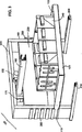
図1の実施形態に示すように、フラクションコレクター装置100は、ディスペンス・ヘッド150の下方の所定位置において、垂直に調節可能な収集ベッド101を備えている。当業者は理解するだろうが、この所定の位置は、様々な位置のうち、任意の位置である。非限定的な例としては、所定の位置は、既知のサイズの収集容器を収容したラックのために適している。他の実施形態においては、所定の位置は、あつらえた収集容器を使用できるように、連続体に沿って調節可能になっている。ディスペンス・ヘッド150は、延長アーム160に可動に取り付けられ、延長アームは、キャリッジ170に可動に取り付けられている。図1に示した実施形態においては、ディスペンス・ヘッド150は、延長アーム160に沿ってY方向に動くことができ、延長アーム160はX方向に動くことができる。当業者は理解するだろうが、X及びYの方向は、任意に割り当てられたもので、限定する意味はない。ディスペンス・ヘッド150がX方向に動き、延長アーム160がY方向に動くような実施形態も想定される。
As shown in the embodiment of FIG. 1, the
図1に示すように、フラクションコレクター100は、左側脚部180と、左側脚部ベース200と、右側脚部190と、右側脚部ベース210とによって支持されている。当業者は理解するだろうが、脚部のベースは、脚部を安定化させるのに適した、任意の形状で良い。図面にはある種の形状のベースを例示しているけれども、ベースはそれに限定される意図ではない。2つの脚部は、上部ブレース220と前部ブレース230とによって結合される。図1の実施形態においては、上部ブレース220と前部ブレース230とが、2つの脚部に永久的に結合されているけれども、更なる実施形態においては、上部ブレース220と前部ブレース230とを、例えば、ネジを用いて、2つの脚部に着脱可能に結合させても良い。追加的な実施形態においては、前部ブレースを支持面へ延ばすことが想定される。いくつかの実施形態においては、脚部、脚部ベース、及びブレースは、フラクションコレクターのための支持装置を形成する。さらに別の実施形態においては、支持装置は、前部ブレースを含まないことが想定される。
As shown in FIG. 1, the
キャリッジ170は、当業者に知られている多数の方法のうちのひとつによって、前部ブレース230の後方に取り付けられる。収集ベッド101はトレイ領域102を有し、トレイ領域には、図示の如く、ラック240が配置され、または、トレイ領域には、ラック装置以外の装置を用いて、個別の収集容器が配置される。収集ベッド101はさらに、2つの収集ベッドアーム110を有し、収集ベッドアームは、収集ベッド101のトレイ領域から延びており、収集ベッドを左側脚部180及び右側脚部190に取り付ける。収集ベッドアーム110によれば、収集ベッド101の垂直な高さを調節できる。
The
図1、図2、及び図3には、収集ベッドを取り付けるために想定される、多数の特定の装置を示している。図1において、左側脚部180と右側脚部190との両方は、一連の前部ペグ140と後部ペグ145とを有している。図示の通り、すべてのペグは固定された位置に設けられているが、当業者が認識するように、ペグは可動にしても良い。図1に示すように、収集ベッドアームは、前部固定箇所120と、後部固定箇所130とを有している。収集ベッド101は、前部固定箇所120を前部ペグ140に係合させ、後部固定箇所130を後部ペグ145に係合させて、左側脚部180と右側脚部190とに取り付けられる。前部ペグ140と後部ペグ145とは、左側脚部180と右側脚部190とに配置され、すべての固定箇所が対応するペグに係合したとき、収集ベッド101は水平になる。
1, 2 and 3 show a number of specific devices envisioned for mounting the collection bed. In FIG. 1, both the
図1に示した実施形態において、収集ベッド101を垂直に調節するには、固定箇所120,130を手作業で係脱させた後、所望の位置に応じて、収集ベッドを上昇又は下降させて、次に、固定箇所120,130を新たな位置にあるペグ140,145に再係合させる。
図2の実施形態は、収集ベッド101をフラクションコレクター100の脚部180,190に取り付けるための別のやり方を示している。図2に示した収集ベッドアーム110は、前部固定孔125と後部固定孔135とを有し、左側脚部180と右側脚部190とは、前部ペグ孔142と後部ペグ孔148とを有している。ペグ孔と固定孔とは、収集ベッド101が水平になるとき、前部固定孔125が前部ペグ孔142に整列され、後部固定孔135が後部ペグ孔148に整列されるように、位置決めされている。固定孔とペグ孔とが整列されたとき、可動なペグ141を挿入すれば、収集ベッド101は脚部に固定される。図示した実施形態においては、ペグ孔とペグとは円筒形の形状になっていたけれども、ペグは、正方形、長方形、及び半円形などを含む、任意の形状で良いことを当業者は理解するだろう。変形例の実施形態においては、収集ベッド101を脚部に固定するために、固定孔及びペグ孔に通してピンが配置される。
In the embodiment shown in FIG. 1, in order to adjust the
The embodiment of FIG. 2 shows another way to attach the
図3は、本発明のさらに別の実施形態を示している。図3において、フラクションコレクターの左側脚部180と右側脚部190とは、外側チャネル250を取り付けられて有している。ある種の実施形態においては、外側チャネル250は取り付けられるものではなく、脚部と一体的な部品になっている。図3の実施形態においては、収集ベッドアーム110を外側チャネル250に挿入することで、収集ベッドを固定された位置に保持する。外側チャネル250は、様々な高さにて、脚部に位置決めされており、収集ベッド101は、フラクションコレクター100に取り付けられたとき、水平になる。当業者によれば、収集ベッド101の高さ調節の範囲を大きく又は小さくするために、数多くのチャネルのサイズ及び間隔が構想される。例えば、外側チャネル250は、現在存在することが当業者に知られている収集容器に従って、構成される。図示した位置のスケール又は位置の数に限定することは、本発明の目的ではない。
FIG. 3 shows yet another embodiment of the present invention. In FIG. 3, the
図4の実施形態は、図3の実施形態と類似した構成になっている。図4に示すように、内部チャネル260は、フラクションコレクター100の左側脚部180と右側脚部190とに凹設されている。この事例においては、収集ベッドアーム110は、内部チャネル260に挿入される。内部チャネル260は、様々な高さにて、脚部に位置決めされており、収集ベッド101は、フラクションコレクター100に取り付けられたとき、水平になる。再言するが、内部チャネルの配置は、限定的な意味ではない。さらに、当業者は理解するだろうが、図3に示した外側チャネル及び図4に示した内部チャネルは、脚部における垂直な側部に示しているけれども、収集ベッドアームが適合する限り、チャネルは、脚部における任意の側部に設けることができる。いくつかの実施形態においては、内部チャネルは脚部を延通している。他の実施形態においては、内部チャネルは、脚部における平行な側部に設けられる。内部チャネルが脚部における平行な側部に設けられるならば、収集ベッドアームは、結合のための少なくともひとつの突起部を含むことが必要である。
The embodiment of FIG. 4 has a configuration similar to that of the embodiment of FIG. As shown in FIG. 4, the
図1乃至図3においては、収集ベッドアーム110を脚部の外側に取り付けていたけれども、上述した任意の取付装置を用いての取付位置は、脚部における内側に向いた部分であっても良いことが想定される。さらに、当業者は理解するだろうが、脚部180,190に代えて、異なるスタイルの脚部を使用しても良い。ある種の実施形態においては、脚部は、他のスタイルを有する脚部と同様に、溝部を備えた脚部を取り巻く。いくつかの実施形態においては、脚部の両方の縁部は、カットアウト又はその他のタイプの切欠を有する。他の実施形態においては、脚部の片側だけが、溝部又は切欠を有する。当業者は理解するだろうが、取付装置の数、サイズ、及び側部は、図示した位置のスケール又は位置の数に限定する意図ではない。
Although the
図5は、代替的なスタイルの実施形態による収集ベッド組立体300を示している。図5に示した実施形態においては、支持装置における脚部は、ロッド330を受け入れ可能な、溝部ないし切欠280を具備している。収集ベッド300の後部縁部290は、脚部180,190に対して支えられ、あるいは、溝部又は切欠にて、収集ベッド101をさらに支持する。図5に示すように、収集ベッドアーム320は、収集ベッドの平面に対して斜めに配置される。アーム320は、図5に示すように、ロッド330によって取り付けられるか、または、ロッドは、片方の脚部から他方の脚部へ部分的にだけ延びる。当業者は理解するだろうが、変形例の実施形態においては、ロッドの延長は変化する。ロッドは、短くても、長くても、依然として本発明の精神の範囲内に含まれる。
FIG. 5 illustrates a
図5の実施形態において、代替的なスタイルの収集ベッド300を垂直に調節するには、ベッド300の前部部分を充分に持ち上げて、後方縁部290を脚部180,190から遊離させ、ロッド330を溝部280から解放し、次に、収集ベッドを所望の位置へと脚部の上下に摺動させる。図5に示した溝部280に加えて、他の実施形態も想定される。例えば、一連の切欠が、収集ベッドトレイにおける後部縁部に相補的に形成された部分を受け入れるようなものが想定される。さらに、切欠は、相補的な形状のキーを受け入れて、ロックされるようにデザインしても良い。
In the embodiment of FIG. 5, to adjust the alternative
本発明においては、機械化された実施形態も想定される。例えば、フラクションコレクターは、液圧昇降機を備えた収集ベッドを具備する。図6に示すように、フラクションコレクター500は、ネジ駆動昇降機520を備えた収集ベッド510を備えても良い。ネジ駆動昇降機520は、ネジ530と、拡張可能な格子540とを具備している。図6に示した実施形態においては、2つのネジ駆動昇降機を示しているけれども、当業者が理解するように、フラクションコレクターと共に機能できる限り、任意の数の昇降機を使用することができる。液圧昇降機又はネジ駆動昇降機を備えた実施形態は、自動駆動装置又は手動駆動装置のいずれかを用いて、動力化しても良い。機械化された実施形態においては、収集ベッドは、フラクションコレクターに取り付けられない。代わりに、収集ベッドは、ステージ上に載置されるか、ステージと完全に一体化されて、ステージは、液圧的方法を介して、または、動力化されたネジ機構を用いて、手動で上昇され又は下降される。そうした実施形態においては、収集ベッドは、装置のディスペンス・ヘッドに対して、確実かつ精密に整列される必要がある。精密な整列を実行するには、装置及び収集ベッドに設けた目印、装置に設けた位置決めレーザ、及び/又は、実験台などのように、装置と支持体との両方に設けた目印が使用される。機械化されたバージョンは、垂直に調節可能な収集ベッドに複雑な層を追加するので、また、ある種の状況においては非実用的であり、また、機械化されたバージョンは、当業者に良く理解できる機構を利用するので、それらの実施形態については、これ以上は説明しない。
In the present invention, mechanized embodiments are also envisaged. For example, the fraction collector comprises a collection bed equipped with a hydraulic elevator. As shown in FIG. 6, the
上述した本発明の実施形態は、いくらか詳細に、明白な理解が得られるように例示的に開示されたけれども、かかる実施形態に対しては、当業者によって、ある種の変更及び改変を施すことができ、それらは、特許請求の範囲に定められた広い観点の本発明から逸脱するものではないことを理解されたい。 Although the embodiments of the present invention described above have been disclosed in some detail for purposes of clarity of understanding, certain changes and modifications may be made to such embodiments by those skilled in the art. It should be understood that they do not depart from the broad aspects of the invention as defined in the claims.
Claims (12)
第1のペグを備えた左側脚部と、第2のペグを備えた右側脚部と、を備えた支持装置と、
支持装置によって可動に支持されたキャリッジと、
キャリッジに結合された延長アームと、
延長アームに可動に結合されたディスペンス・ヘッドと、
を有し、このディスペンス・ヘッド及び上記キャリッジは、第1の平面において、支持装置に対して動くことができ、
更に、支持装置に可動に結合された収集ベッドを有し、この収集ベッドは、第1の平面に対して垂直である第2の平面において、支持装置を動かすことなく、可動になっており、
さらに、上記収集ベッドは、収集ベッドアームと、収集容器を保持するためのトレイ領域と、を備え、
上記収集ベッドアームは、上記トレイ領域から延びており、上記第1のペグ又は上記第2のペグを受けるようにデザインされた固定箇所を備えていることを特徴とするフラクションコレクター。A fraction collector,
A support device comprising a left leg with a first peg and a right leg with a second peg ;
A carriage movably supported by a support device;
An extension arm coupled to the carriage;
A dispensing head movably coupled to the extension arm;
Has, in this dispensing head and the carriage, the first plane can move relative to the support device,
Further comprising a collection bed movably coupled to the support device, the collection bed in a second plane which is perpendicular to the first plane without moving the support device, which becomes movable,
Furthermore, the collection bed comprises a collection bed arm and a tray area for holding a collection container,
The fraction collector , wherein the collection bed arm extends from the tray region and includes a fixed location designed to receive the first peg or the second peg .
第1の孔を備えた左側脚部と、第2の孔を備えた右側脚部と、を備えた支持装置と、
支持装置によって可動に支持されたキャリッジと、
キャリッジに結合された延長アームと、
延長アームに可動に結合されたディスペンス・ヘッドと、
を有し、このディスペンス・ヘッド及び上記キャリッジは、第1の平面において、支持装置に対して動くことができ、
更に、支持装置に可動に結合された収集ベッドを有し、この収集ベッドは、第1の平面に対して垂直である第2の平面において、支持装置を動かすことなく、可動になっており、
さらに、上記収集ベッドは、収集ベッドアームと、収集容器を保持するためのトレイ領域と、を備え、
上記収集ベッドアームは、上記トレイ領域から延びており、収集ベッドアームはそれぞれ固定箇所を備え、第1の孔と第2の孔と固定箇所とは、ペグを受け入れるようにデザインされていることを特徴とするフラクションコレクター。 A fraction collector,
A support device comprising a left leg with a first hole and a right leg with a second hole;
A carriage movably supported by a support device;
An extension arm coupled to the carriage;
A dispensing head movably coupled to the extension arm;
The dispensing head and the carriage can move relative to the support device in a first plane;
And a collection bed movably coupled to the support device, the collection bed being movable in a second plane perpendicular to the first plane without moving the support device;
Furthermore, the collection bed comprises a collection bed arm and a tray area for holding a collection container,
The collection bed arms extend from the tray area, the collection bed arms each comprise a fixed portion, a first hole and the fixing portion and the second hole, that it is designed to receive a peg Characteristic fraction collector.
左側脚部及び右側脚部を備えた支持装置と、
支持装置によって可動に支持されたキャリッジと、
キャリッジに結合された延長アームと、
延長アームに可動に結合されたディスペンス・ヘッドと、
を有し、このディスペンス・ヘッド及び上記キャリッジは、第1の平面において、支持装置に対して動くことができ、
更に、支持装置に可動に結合された収集ベッドを有し、この収集ベッドは、第1の平面に対して垂直である第2の平面において、支持装置を動かすことなく、可動になっており、
さらに、上記収集ベッドは、収集ベッドアームと、収集容器を保持するためのトレイ領域と、を備え、
右側脚部と左側脚部とは、外側チャネルを具備し、収集ベッドアームは、外側チャネルに挿入可能になっていることを特徴とするフラクションコレクター。 A fraction collector,
A support device comprising a left leg and a right leg;
A carriage movably supported by a support device;
An extension arm coupled to the carriage;
A dispensing head movably coupled to the extension arm;
The dispensing head and the carriage can move relative to the support device in a first plane;
And a collection bed movably coupled to the support device, the collection bed being movable in a second plane perpendicular to the first plane without moving the support device;
Furthermore, the collection bed comprises a collection bed arm and a tray area for holding a collection container,
A fraction collector, wherein the right leg and the left leg comprise an outer channel, and the collection bed arm is insertable into the outer channel.
左側脚部及び右側脚部を備えた支持装置と、
支持装置によって可動に支持されたキャリッジと、
キャリッジに結合された延長アームと、
延長アームに可動に結合されたディスペンス・ヘッドと、
を有し、このディスペンス・ヘッド及び上記キャリッジは、第1の平面において、支持装置に対して動くことができ、
更に、支持装置に可動に結合された収集ベッドを有し、この収集ベッドは、第1の平面に対して垂直である第2の平面において、支持装置を動かすことなく、可動になっており、
さらに、上記収集ベッドは、収集ベッドアームと、収集容器を保持するためのトレイ領域と、を備え、
右側脚部と左側脚部とは、内部チャネルを具備し、収集ベッドアームは、内部チャネルに挿入可能になっていることを特徴とするフラクションコレクター。 A fraction collector,
A support device comprising a left leg and a right leg;
A carriage movably supported by a support device;
An extension arm coupled to the carriage;
A dispensing head movably coupled to the extension arm;
The dispensing head and the carriage can move relative to the support device in a first plane;
And a collection bed movably coupled to the support device, the collection bed being movable in a second plane perpendicular to the first plane without moving the support device;
Furthermore, the collection bed comprises a collection bed arm and a tray area for holding a collection container,
A fraction collector, wherein the right leg and the left leg comprise an internal channel, and the collection bed arm is insertable into the internal channel.
左側脚部及び右側脚部を備えた支持装置と、
支持装置によって可動に支持されたキャリッジと、
キャリッジに結合された延長アームと、
延長アームに可動に結合されたディスペンス・ヘッドと、
を有し、このディスペンス・ヘッド及び上記キャリッジは、第1の平面において、支持装置に対して動くことができ、
更に、支持装置に可動に結合された収集ベッドを有し、この収集ベッドは、第1の平面に対して垂直である第2の平面において、支持装置を動かすことなく、可動になっており、
さらに、上記収集ベッドは、収集ベッドアームと、収集容器を保持するためのトレイ領域と、を備え、
ロッドをさらに備え、収集ベッドアームは、ロッドの端部を受け入れ可能な孔を具備し、第1の脚部及び右側脚部は、収集ベッドとは反対側の縁部に沿って、ロッドを支持可能な溝部を具備していることを特徴とするフラクションコレクター。 A fraction collector,
A support device comprising a left leg and a right leg;
A carriage movably supported by a support device;
An extension arm coupled to the carriage;
A dispensing head movably coupled to the extension arm;
The dispensing head and the carriage can move relative to the support device in a first plane;
And a collection bed movably coupled to the support device, the collection bed being movable in a second plane perpendicular to the first plane without moving the support device;
Furthermore, the collection bed comprises a collection bed arm and a tray area for holding a collection container,
The collection bed arm further includes a hole capable of receiving the end of the rod, and the first leg and the right leg support the rod along an edge opposite the collection bed. A fraction collector characterized by having a possible groove.
第1の平面内で動くことができる、フラクションコレクターのディスペンス・ヘッドから、収集ベッドの適切な変位を決定する段階を有し、
上記ディスペンスヘッドの支持装置を動かすことなく、第1の平面に対して垂直である第2の平面に対して垂直である第2の平面内で収集ベッドをディスペンス・ヘッドと整列させる段階を有し、上記支持装置は、第1のペグを備えた左側脚部と、第2のペグを備えた右側脚部と、を備え、
収集ベッドアームを用いて、整列された収集ベッドを上記ディスペンス・ヘッドの支持装置に取り付ける段階を有し、上記収集ベッドアームは、上記収集ベッドから延びており、上記第1のペグ又は上記第2のペグを受けるようにデザインされた固定箇所を備えていることを特徴とする方法。A method for using a fraction collector,
Can move in a first plane, from the dispensing head fraction collector, it has a step of determining the appropriate displacement of the collection bed,
Without moving the support device of the dispensing head has a step of aligning the dispensing head collection bed in a second plane which is perpendicular to the second plane is perpendicular to the first plane The support device includes a left leg provided with a first peg and a right leg provided with a second peg ,
Attaching an aligned collection bed to the dispense head support using a collection bed arm, the collection bed arm extending from the collection bed, the first peg or the second peg A method characterized in that it comprises a fixed part designed to receive a peg .
Applications Claiming Priority (2)
| Application Number | Priority Date | Filing Date | Title |
|---|---|---|---|
| US60910504P | 2004-09-10 | 2004-09-10 | |
| PCT/US2005/032178 WO2006029330A2 (en) | 2004-09-10 | 2005-09-08 | Fraction collector with adjustable tray |
Publications (3)
| Publication Number | Publication Date |
|---|---|
| JP2008512681A JP2008512681A (en) | 2008-04-24 |
| JP2008512681A5 JP2008512681A5 (en) | 2008-10-16 |
| JP4597195B2 true JP4597195B2 (en) | 2010-12-15 |
Family
ID=36037023
Family Applications (1)
| Application Number | Title | Priority Date | Filing Date |
|---|---|---|---|
| JP2007531370A Active JP4597195B2 (en) | 2004-09-10 | 2005-09-08 | Fraction collector with adjustable tray |
Country Status (11)
| Country | Link |
|---|---|
| US (2) | US7361269B2 (en) |
| EP (1) | EP1804949B1 (en) |
| JP (1) | JP4597195B2 (en) |
| KR (2) | KR101347563B1 (en) |
| CN (1) | CN100502995C (en) |
| AT (1) | ATE497814T1 (en) |
| AU (1) | AU2005282363B2 (en) |
| CA (1) | CA2579248A1 (en) |
| DE (1) | DE602005026305D1 (en) |
| RU (1) | RU2379086C2 (en) |
| WO (1) | WO2006029330A2 (en) |
Families Citing this family (12)
| Publication number | Priority date | Publication date | Assignee | Title |
|---|---|---|---|---|
| US7138050B2 (en) * | 2003-05-29 | 2006-11-21 | Shimadzu Corporation | Fractionating/collecting device of liquid chromatograph |
| DE102006022953B3 (en) * | 2006-05-17 | 2007-12-20 | Bruker Biospin Gmbh | Method for coupling a gas chromatograph with an NMR spectrometer and associated apparatus |
| US8752418B2 (en) * | 2009-06-09 | 2014-06-17 | Ge Healthcare Bio-Sciences Ab | Device for reducing loss of liquid during fraction collection |
| CN101598712A (en) * | 2009-06-30 | 2009-12-09 | 上海华质生物技术有限公司 | Trace distillate collector |
| US9731219B2 (en) | 2011-06-17 | 2017-08-15 | Waters Technologies Corporation | Methods and devices for open-bed atmospheric collection for supercritical fluid chromatography |
| EP2864761B1 (en) * | 2012-06-22 | 2020-12-16 | Bio-Rad Laboratories, Inc. | Two station sample and washing system |
| US9933399B2 (en) * | 2012-08-31 | 2018-04-03 | Waters Technologies Corporation | Separation efficiency in supercritical fluid chromatography |
| US9884266B2 (en) * | 2013-07-08 | 2018-02-06 | Orlab Chromatography, Llc | Fluoropolymer pneumatically/hydraulically actuated liquid chromatographic system for use with harsh reagents |
| JP6413900B2 (en) | 2015-04-03 | 2018-10-31 | 株式会社島津製作所 | Fraction collector |
| CN104897827B (en) * | 2015-06-16 | 2016-08-24 | 常州三泰科技有限公司 | Avoid the preparative fraction collector of sample loss |
| GB201601667D0 (en) | 2016-01-29 | 2016-03-16 | Ge Healthcare Bio Sciences Ab | Improvements in and relating to liquid fraction collectors |
| GB202009615D0 (en) | 2020-06-24 | 2020-08-05 | Cytiva Sweden Ab | A fraction collector and a method for operating the same |
Family Cites Families (36)
| Publication number | Priority date | Publication date | Assignee | Title |
|---|---|---|---|---|
| US3151639A (en) * | 1961-10-23 | 1964-10-06 | Instrumentation Specialties Co | Apparatus for making chemical separations |
| US3168124A (en) * | 1961-11-13 | 1965-02-02 | Beckman Instruments Inc | Fraction collector |
| NL292856A (en) * | 1962-05-17 | |||
| US3268117A (en) * | 1965-04-09 | 1966-08-23 | Beckman Instruments Inc | Dispensing head |
| US3418084A (en) * | 1966-10-27 | 1968-12-24 | Instrumentation Specialties Co | Rectangular fraction collector |
| US3443439A (en) * | 1967-12-05 | 1969-05-13 | Edgardo A Cruz | Automatic sampler |
| US3625265A (en) | 1970-01-07 | 1971-12-07 | Warren E Gilson | Fraction collector |
| US3943983A (en) * | 1974-05-23 | 1976-03-16 | Buchler Instruments, Div. Of Searle Analytic, Inc. | Moisture sensing systems for electrically operated liquid-handling devices |
| JPS5525736Y2 (en) * | 1974-07-31 | 1980-06-20 | ||
| US4077444A (en) * | 1975-02-12 | 1978-03-07 | Gilson Warren E | Fraction collector |
| JPS6019314B2 (en) * | 1976-06-28 | 1985-05-15 | 森下製薬株式会社 | 2,3,6,7↓-tetrahydro↓-3↓-oxo↓-5H↓-pyridazino[3,4↓-b][1,4]oxazine derivative |
| SE7614077L (en) * | 1976-12-14 | 1978-06-15 | Pharmacia Fine Chemicals Ab | PROGRAMMABLE FRACTION COLLECTOR |
| US4147250A (en) * | 1977-03-25 | 1979-04-03 | Packard Instrument Company, Inc. | Storage and indexing mechanism for multiple sample containers |
| US4166094A (en) * | 1978-05-22 | 1979-08-28 | The Perkin-Elmer Corporation | Automatic fluid sampling transport system |
| JPS5525736A (en) | 1978-08-10 | 1980-02-23 | Sanyo Electric Co Ltd | Control circuit for combustor |
| JPS5547610U (en) * | 1978-09-25 | 1980-03-28 | ||
| US4356909A (en) * | 1980-07-18 | 1982-11-02 | Buchler Instruments, Inc. | Fraction collector |
| US4422151A (en) * | 1981-06-01 | 1983-12-20 | Gilson Robert E | Liquid handling apparatus |
| FR2572180B1 (en) * | 1984-10-24 | 1987-03-20 | Eric Marteau D Autry | METHOD AND APPARATUS FOR REPAIRING SAMPLES FOR ANALYSIS |
| JPH029865A (en) | 1987-02-27 | 1990-01-12 | Yamanouchi Pharmaceut Co Ltd | Novel peptide derivative |
| JPH0712924Y2 (en) * | 1987-11-27 | 1995-03-29 | ガスクロ工業株式会社 | Drain piece for liquid collection |
| US4862932A (en) * | 1988-04-20 | 1989-09-05 | Bio-Rad Laboratories, Inc. | Fraction collector |
| JPH029865U (en) * | 1988-06-30 | 1990-01-22 | ||
| JPH0244257A (en) * | 1988-08-04 | 1990-02-14 | Yasunobu Tsukioka | Dispencing/suction apparatus and method for sucking and discharging chemical liquid/washing water by the apparatus |
| US5045208A (en) * | 1989-10-27 | 1991-09-03 | Helena Laboratories Corporation | Column analyzer system |
| JPH0750088B2 (en) * | 1990-09-29 | 1995-05-31 | 株式会社島津製作所 | Liquid chromatograph preparative device |
| FR2688313A1 (en) * | 1992-03-04 | 1993-09-10 | Marteau D Autry Eric | AUTOMATIC FILTERING AND IDENTIFICATION OF SAMPLES. |
| JPH0592717U (en) * | 1992-05-19 | 1993-12-17 | 武田薬品工業株式会社 | Fraction collector |
| CN2205232Y (en) * | 1994-04-15 | 1995-08-16 | 沈阳药科大学制药厂 | Chromatography column receiving device |
| DE19704477A1 (en) * | 1997-02-06 | 1998-08-13 | Solvay Pharm Gmbh | Device and method for parallel chromatography |
| US6133045A (en) * | 1998-02-27 | 2000-10-17 | Hamilton Company | Automated sample treatment system: apparatus and method |
| US6355164B1 (en) * | 1999-10-29 | 2002-03-12 | Ontogen Corporation | Sample collection apparatus and method for multiple channel high throughput purification |
| US6551464B1 (en) * | 2000-02-17 | 2003-04-22 | Howard Kimel | Distillation/reflux equipment |
| US6450218B1 (en) * | 2001-02-02 | 2002-09-17 | Amersham Pharmacia Biotech Ab | Fraction collector |
| US6812030B2 (en) * | 2001-04-25 | 2004-11-02 | Biotrove, Inc. | System and method for high throughput sample preparation and analysis using column chromatography |
| US7138050B2 (en) * | 2003-05-29 | 2006-11-21 | Shimadzu Corporation | Fractionating/collecting device of liquid chromatograph |
-
2005
- 2005-09-08 KR KR1020077008173A patent/KR101347563B1/en active IP Right Grant
- 2005-09-08 DE DE602005026305T patent/DE602005026305D1/en active Active
- 2005-09-08 EP EP05796377A patent/EP1804949B1/en active Active
- 2005-09-08 CA CA002579248A patent/CA2579248A1/en not_active Abandoned
- 2005-09-08 KR KR1020127033641A patent/KR20130018940A/en not_active Application Discontinuation
- 2005-09-08 RU RU2007112508/12A patent/RU2379086C2/en not_active IP Right Cessation
- 2005-09-08 AU AU2005282363A patent/AU2005282363B2/en not_active Ceased
- 2005-09-08 WO PCT/US2005/032178 patent/WO2006029330A2/en active Application Filing
- 2005-09-08 US US11/221,589 patent/US7361269B2/en active Active
- 2005-09-08 CN CNB2005800303605A patent/CN100502995C/en active Active
- 2005-09-08 AT AT05796377T patent/ATE497814T1/en not_active IP Right Cessation
- 2005-09-08 JP JP2007531370A patent/JP4597195B2/en active Active
-
2008
- 2008-03-25 US US12/054,665 patent/US8114281B2/en active Active
Also Published As
| Publication number | Publication date |
|---|---|
| KR20070054239A (en) | 2007-05-28 |
| CN101014396A (en) | 2007-08-08 |
| JP2008512681A (en) | 2008-04-24 |
| EP1804949B1 (en) | 2011-02-09 |
| WO2006029330A2 (en) | 2006-03-16 |
| US20060054544A1 (en) | 2006-03-16 |
| WO2006029330A3 (en) | 2006-10-05 |
| CA2579248A1 (en) | 2006-03-16 |
| CN100502995C (en) | 2009-06-24 |
| KR20130018940A (en) | 2013-02-25 |
| AU2005282363A1 (en) | 2006-03-16 |
| RU2007112508A (en) | 2008-10-27 |
| ATE497814T1 (en) | 2011-02-15 |
| EP1804949A4 (en) | 2009-03-11 |
| KR101347563B1 (en) | 2014-01-03 |
| AU2005282363B2 (en) | 2010-09-23 |
| EP1804949A2 (en) | 2007-07-11 |
| US8114281B2 (en) | 2012-02-14 |
| DE602005026305D1 (en) | 2011-03-24 |
| US7361269B2 (en) | 2008-04-22 |
| US20080173577A1 (en) | 2008-07-24 |
| RU2379086C2 (en) | 2010-01-20 |
Similar Documents
| Publication | Publication Date | Title |
|---|---|---|
| JP4597195B2 (en) | Fraction collector with adjustable tray | |
| KR100626630B1 (en) | Plate locator for precision liquid handler | |
| JP6933903B2 (en) | Device for mounting multiple actuator modules | |
| US20080025878A1 (en) | Sample tube holder | |
| US6973846B2 (en) | Sample handling device for an analytical instrument | |
| EP1216406A1 (en) | Devices for use in maldi mass spectrometry | |
| US20030215361A1 (en) | Liquid dispensing and handling system | |
| US11143668B2 (en) | Sampler device | |
| US20110146422A1 (en) | Slidable autosampler tray | |
| US20220065888A1 (en) | Pipette accessory for reliable liquid handling | |
| US20140065036A1 (en) | Tray Support for Chromatographic Equipment | |
| CN210846433U (en) | Multi-pipeline liquid transfer device | |
| CN219218036U (en) | Carousel formula nucleic acid extraction device | |
| CN212083194U (en) | Salt mist test device for shaft part | |
| US20160346783A1 (en) | Adjustable device for multi-channel pipette | |
| CN219596693U (en) | Virus sampling tube specimen holder | |
| CN218022995U (en) | Suction head box for full-automatic cup separating processing system | |
| US10933421B2 (en) | Well strip extractor press and method | |
| JP2013518263A (en) | Positioning device for sample dispensing apparatus, sample dispensing apparatus with positioning device, and positioning method | |
| WO2000062055A1 (en) | Method and apparatus for developing multiple thin layer chromatography plates |
Legal Events
| Date | Code | Title | Description |
|---|---|---|---|
| A521 | Request for written amendment filed |
Free format text: JAPANESE INTERMEDIATE CODE: A523 Effective date: 20080901 |
|
| A621 | Written request for application examination |
Free format text: JAPANESE INTERMEDIATE CODE: A621 Effective date: 20080901 |
|
| A131 | Notification of reasons for refusal |
Free format text: JAPANESE INTERMEDIATE CODE: A131 Effective date: 20100222 |
|
| A521 | Request for written amendment filed |
Free format text: JAPANESE INTERMEDIATE CODE: A523 Effective date: 20100510 |
|
| TRDD | Decision of grant or rejection written | ||
| A01 | Written decision to grant a patent or to grant a registration (utility model) |
Free format text: JAPANESE INTERMEDIATE CODE: A01 Effective date: 20100823 |
|
| A01 | Written decision to grant a patent or to grant a registration (utility model) |
Free format text: JAPANESE INTERMEDIATE CODE: A01 |
|
| A61 | First payment of annual fees (during grant procedure) |
Free format text: JAPANESE INTERMEDIATE CODE: A61 Effective date: 20100921 |
|
| R150 | Certificate of patent or registration of utility model |
Ref document number: 4597195 Country of ref document: JP Free format text: JAPANESE INTERMEDIATE CODE: R150 Free format text: JAPANESE INTERMEDIATE CODE: R150 |
|
| FPAY | Renewal fee payment (event date is renewal date of database) |
Free format text: PAYMENT UNTIL: 20131001 Year of fee payment: 3 |
|
| R250 | Receipt of annual fees |
Free format text: JAPANESE INTERMEDIATE CODE: R250 |
|
| R250 | Receipt of annual fees |
Free format text: JAPANESE INTERMEDIATE CODE: R250 |
|
| R250 | Receipt of annual fees |
Free format text: JAPANESE INTERMEDIATE CODE: R250 |
|
| R250 | Receipt of annual fees |
Free format text: JAPANESE INTERMEDIATE CODE: R250 |
|
| R250 | Receipt of annual fees |
Free format text: JAPANESE INTERMEDIATE CODE: R250 |
|
| R250 | Receipt of annual fees |
Free format text: JAPANESE INTERMEDIATE CODE: R250 |
|
| R250 | Receipt of annual fees |
Free format text: JAPANESE INTERMEDIATE CODE: R250 |
|
| R250 | Receipt of annual fees |
Free format text: JAPANESE INTERMEDIATE CODE: R250 |
|
| R250 | Receipt of annual fees |
Free format text: JAPANESE INTERMEDIATE CODE: R250 |
|
| R250 | Receipt of annual fees |
Free format text: JAPANESE INTERMEDIATE CODE: R250 |
|
| R250 | Receipt of annual fees |
Free format text: JAPANESE INTERMEDIATE CODE: R250 |