JP4596824B2 - Image forming apparatus - Google Patents
Image forming apparatus Download PDFInfo
- Publication number
- JP4596824B2 JP4596824B2 JP2004171740A JP2004171740A JP4596824B2 JP 4596824 B2 JP4596824 B2 JP 4596824B2 JP 2004171740 A JP2004171740 A JP 2004171740A JP 2004171740 A JP2004171740 A JP 2004171740A JP 4596824 B2 JP4596824 B2 JP 4596824B2
- Authority
- JP
- Japan
- Prior art keywords
- recording material
- image
- timer
- time
- detected
- Prior art date
- Legal status (The legal status is an assumption and is not a legal conclusion. Google has not performed a legal analysis and makes no representation as to the accuracy of the status listed.)
- Expired - Fee Related
Links
Images


Description
本発明は、両面画像形成可能な画像形成装置に関するものである。 The present invention relates to an image forming apparatus capable of forming double-sided images.
従来から、両面画像形成が可能な画像形成装置が知られており、この画像形成装置においては、給紙された用紙の第1面に対して画像形成が行われると、この画像形成後の用紙は、本装置外に排出されず、逆回転された排紙ローラ対により、搬送路に導かれ、さらに複数の搬送ローラ対によりレジストローラ対まで搬送され、これにより当該用紙が第1面から第2面に反転され、当該用紙の第2面に対して画像形成が行われ、転写、定着後、本装置外に排出される。このような両面が像形成動作に関しては特許文献1に記載されている。 2. Description of the Related Art Conventionally, an image forming apparatus capable of double-sided image formation is known. In this image forming apparatus, when image formation is performed on a first surface of a fed sheet, the sheet after image formation is formed. Is not discharged out of the apparatus, but is guided to the transport path by a pair of paper discharge rollers rotated in reverse, and further transported to a pair of registration rollers by a plurality of transport roller pairs. Inverted to two sides, image formation is performed on the second side of the paper, and after transfer and fixing, the paper is discharged out of the apparatus. Such double-sided image forming operation is described in Patent Document 1.
しかしながら、このような方法によれば、当該用紙が排紙センサにより検知された後の反転動作中において、当該用紙が、例えば、排紙ローラ対と搬送ローラ対とに跨って緊急停止し、その後、本画像形成装置の動作が再開されたとき、一方で、排紙ローラ対が正回転して当該用紙を排出しようとし、他方で、搬送ローラ対が正回転して当該用紙を搬送しようとし、これにより、当該用紙が折れ曲がったり破れたりすることがあった。 However, according to such a method, during the reversing operation after the paper is detected by the paper discharge sensor, the paper is urgently stopped across, for example, the paper discharge roller pair and the conveyance roller pair, and then When the operation of the image forming apparatus is resumed, on the one hand, the discharge roller pair rotates forward to try to discharge the paper, and on the other hand, the transport roller pair rotates forward to try to convey the paper. As a result, the paper may be bent or torn.
そこで、本発明は、このような問題を解決し、排紙ローラ対と搬送ローラ対との間に停止した記録材を、本装置の動作再開後に、引き続き搬送することができる画像形成装置および搬送制御方法を提供することを目的とする。 Therefore, the present invention solves such a problem, and an image forming apparatus capable of continuing to convey a recording material stopped between a paper discharge roller pair and a conveyance roller pair after the operation of the apparatus is resumed. An object is to provide a control method.
請求項1の画像形成装置は、記録材に画像を形成する画像形成手段と、前記画像形成手段により画像が形成された記録材を検出する排紙センサと、前記排紙センサにより記録材の先端が検出されてから記録材の後端が検出されるまでの時間を計測するタイマと、画像が形成された記録材を排出する排紙ローラと、第1面に画像が形成された記録材の第2面に画像を形成するために前記排紙ローラを、記録材を排紙するための正回転から記録材を反転するための逆回転に切り換えて第1面に画像が形成された記録材を反転する搬送制御部と、を有する画像形成装置において、前記搬送制御部は、前記排紙ローラが逆回転することにより第1面に画像が形成された記録材が反転されると、前記タイマにより記録材が反転搬送されている時間の計測を開始し、前記排紙ローラによって反転搬送されている途中で停止状態となると前記タイマによる時間の計測を停止し、前記停止状態から記録材の搬送を再開する場合に、記録材の先端が検出されてから後端が検出されるまでの時間から記録材が反転搬送されている時間を減算した時間が経過するまでは前記排紙ローラを逆回転させて第1面に画像が形成された記録材を搬送し、前記記録材の先端が検出されてから後端が検出されるまでの時間から記録材が反転搬送されている時間を減算した時間が経過した後は前記排紙ローラを正回転に切り換えることを特徴とする。
The image forming apparatus according to claim 1, an image forming unit that forms an image on a recording material, a paper discharge sensor that detects a recording material on which an image is formed by the image forming unit, and a leading edge of the recording material by the paper discharge sensor A timer for measuring the time from when the recording material is detected until the trailing edge of the recording material is detected, a paper discharge roller for discharging the recording material on which the image is formed, and a recording material on which the image is formed on the first surface the paper discharge rollers to form the images on the second surface, the image is formed on the first surface is switched to the reverse rotation to reverse the recording material from the forward rotation for discharging the recording material recorded in the image forming apparatus including a transfer control section for inverting the timber, wherein the transport control unit, when the recording material in which the sheet discharge roller image is formed on the first surface by reverse rotation Ru is inverted, the Measuring the time the recording material is being reversed and conveyed by a timer Started, the in the course of being inverted conveyed by sheet ejection rollers stops measurement of time by the timer and that Do the stop state, when resuming the conveyance of the recording material from the stopped state, the leading end of the recording material image on the first surface by the time the recording material from the time from the detection to the rear end is detected by subtracting the time being reverse conveyance has passed by reversely rotating said paper discharge roller is formed After the recording material is transported and the time from when the leading edge of the recording material is detected until the trailing edge is detected is subtracted from the time during which the recording material is transported in reverse, the paper discharge roller is moved forward. It is characterized by switching to rotation.
本発明は、上記のように構成したので、排紙ローラ対と搬送ローラ対との間に停止した記録材を、本装置の動作再開後に、引き続き搬送することができる。 Since the present invention is configured as described above, the recording material stopped between the paper discharge roller pair and the conveyance roller pair can be continuously conveyed after the operation of the apparatus is resumed.
以下、本発明の実施の形態を図面を参照して詳細に説明する。
<第1の実施の形態>
図1は本発明の第1の実施の形態を示す。これは、カラー画像形成装置の例であり、この構造を図2に示す。
Hereinafter, embodiments of the present invention will be described in detail with reference to the drawings.
<First Embodiment>
FIG. 1 shows a first embodiment of the present invention. This is an example of a color image forming apparatus, and its structure is shown in FIG.
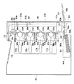
図2のカラー画像形成装置101は、用紙213を収納するカセットシート供給ユニット202bと、ユーザによって手差しで用紙213が送り込まれるマルチシート供給トレイ202aと、用紙213をカセットシート供給ユニット202b及びマルチシート供給トレイ202aから供給するシート供給ユニット219と、画像処理を行う画像形成部208とを備えている。
The color
画像形成部218は、マゼンタ、シアン、イエロー、ブラックの各色に対応する4つの感光体ドラム215a、215b、215c、215dと、感光体ドラム215a、215b、215c、215dの表面を均一に帯電する帯電器217a、217b、217c、217dと、レーザビームを照射して感光体ドラム215a、215b、215c、215d上に静電潜像を形成する露光手段としての光学部117a、117b、117c、117dと、静電潜像にトナーを付着させてトナー像として顕像化する現像器216a、216b、216c、216dと、感光体ドラム215上のトナー像を用紙213に転写させる転写手段としての転写ローラ208a、208b、208c、208d等とにより構成されている。
The image forming unit 218 uniformly charges the surfaces of the four
帯電器217と現像器216は、感光体ドラム215の周囲に、感光ドラム215の回転方向に従って順に配設されている。ここで、感光体ドラム215と、帯電器217と、現像器216は、一体的にカートリッジ化されプロセスカートリッジ206a、206b、206c、206dを形成している。
The charger 217 and the developing unit 216 are sequentially arranged around the photosensitive drum 215 in accordance with the rotation direction of the photosensitive drum 215. Here, the photosensitive drum 215, the charger 217, and the developing unit 216 are integrally formed as a cartridge to form
シート供給ユニット219によって供給された用紙213は、用紙搬送方向上流側(図の下方)から下流側(図の上方)へ向かって搬送される。この間、搬送路201に沿って配設されたレジストセンサ110と、定着前センサ111と、排紙センサ112とによって、用紙213が、適宜、検出される。
The
レジストセンサ110と、定着前センサ111と、排紙センサ112とにより、用紙213が検出されるタイミングに同期して、画像形成部218の各画像形成プロセスが動作し、プロセスカートリッジ206によって、マゼンタ、シアン、イエロー、ブラックの順に、各色のトナー像が、用紙213に、順次、重畳転写される。その後、用紙213に重畳転写されたカラートナー像は、定着器214によって加熱及び加圧され、用紙213の第1面に溶融定着され、定着後の用紙213は排出トレイ210に排出される。
Each image forming process of the image forming unit 218 operates in synchronization with the timing at which the
もし、用紙213の第2面にも画像を形成する場合には、用紙213を第1面から第2面に反転させるため、排紙センサ112により用紙213の後端が検出されたタイミングに同期して排紙ローラ対209を逆回転させて、用紙213を搬送路に案内し、搬送路に案内された用紙213は、搬送ローラ211a、211b、211cによって搬送路を搬送され、再び画像形成部208へ搬送され、これにより、用紙213が第1面から第2面に反転される。
If an image is also formed on the second side of the
画像形成部208によって形成されたカラートナー像が、用紙213の第2面に転写され、用紙213上に転写されたカラートナー像が定着器214により溶融定着され、定着後の用紙213は排出トレイ210に排出される。
The color toner image formed by the image forming unit 208 is transferred to the second surface of the
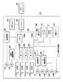
図1を説明する。図1において、図2と同一部分は同一符号を付してある。カラー画像形成装置101は、ホストコンピュータ104と直接またはネットワークを介して接続してある。ホストコンピュータ104により作成された画像形成データは、コントローラ103により受信され、画像信号に変換される。コントローラ103は、制御部102に状態を問い合わせ、画像形成可能状態であることを確認した後、制御部102に画像形成開始の指示を出す。画像形成開始指示を受けた制御部102は、接続された搬送制御部105と、定着駆動制御部106と、光学部117a、117b、117c、117dと、ドラム駆動制御部108と、給紙制御部107とを制御して、各負荷を起動するなどの画像形成準備を開始する。
Referring to FIG. 1, the same parts as those in FIG. 2 are denoted by the same reference numerals. The color
制御部102は、第1タイマ102fと、第2タイマ102sと、第3タイマ102tと、揮発性のメモリ102mとを有し、第1タイマ102fと、第2タイマ102sと、第3タイマ102tとのインクリメント、停止、デクリメントを制御し、第1タイマ102fと、第2タイマ102sと、第3タイマ102tのタイマ値をメモリ102mに記憶し、メモリ102へのリードライトを制御する。
The
搬送制御部105は、制御部102の制御に従って、搬送モータ113を駆動制御し、これにより、転写ローラ208a、208b、208c、208dと、搬送ローラ211a、211b、211cとの駆動を制御する。定着駆動制御部106は、定着モータ114を駆動することによって、定着器214と排紙ローラ対209の駆動を制御する。給紙制御部107は、給紙モータ115を駆動することによって、給紙ピックアップローラ203a、203bと、給紙搬送ローラ204a、204bと、レジストローラ205との駆動を制御する。ドラム駆動制御部108は、ドラムモータ116a、116b、116c、116dを駆動することによって、プロセスカートリッジ206a、206b、206c、206dの駆動を制御する。
The
画像形成準備が完了すると、制御部102が給紙制御部107に給紙指示を出すことにより、シート供給ユニット219によって用紙213が給紙開始される。この時、制御部102は、画像形成中状態に遷移し、画像形成中状態に遷移したことをコントローラ103に通知する。給紙された用紙213の先端がレジストセンサ110によって検出されると、制御部102は所定時間後に画像形成開始信号をコントローラ103に送出する。画像形成開始信号を受信したコントローラ103は、画像形成開始信号に同期して画像信号を出力する。
When the image formation preparation is completed, the
コントローラ103が出力した画像信号は、光学部117a〜dによって、レーザビームのオンオフ信号に変調され、感光ドラム215上に露光される。
The image signal output from the
用紙213が搬送路201上を搬送されるに伴い、画像形成部218が制御され、用紙213上にカラー画像が形成される。画像形成プロセスが正常に終了し、排紙センサ112により用紙213の後端が検出された場合、制御部102は画像形成が正常に終了したと判断し、再び画像形成可能状態になったことをコントローラ103に通知する。
As the
上記の両面画像形成動作において、用紙213を搬送路201に案内した後、次の用紙の搬送に備えて排紙ローラ対209の回転方向を正回転に戻す必要がある。排紙ローラ対209の回転方向を正回転に戻すタイミングは、排紙センサ112を用紙213が通過する時間に基いて決定される。
In the above-described double-sided image forming operation, after the
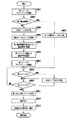
図3は、用紙を搬送路201へ案内する際の搬送制御部105による制御手順を示すフローチャートである。排紙センサ112により用紙213の先端が検出されるまで待ち(S301)、排紙センサ112により用紙213の先端が検出されると、第1タイマ102fをクリアし、第1タイマ102fのインクリメントを開始し(S302)、排紙センサ112により用紙213の後端が検出されるまで待つ(S303)。そして、排紙センサ112により用紙213の後端が検出されると、第1タイマ102fのインクリメントを停止して(S304)、第1タイマ102fのデクリメントを開始する(S305)とともに、排紙ローラ対209を逆回転させる。
FIG. 3 is a flowchart illustrating a control procedure by the
ジャムなどに起因して用紙213の搬送が停止していない場合には(S306)、第1タイマ102fが0になるまで待ち(S307)、第1タイマ102fが0になったとき、排紙ローラ対209を正回転に戻す。他方、ジャムなどに起因して用紙213の搬送が停止した場合には、排紙ローラ209と搬送ローラ211a、211b、211cとの駆動を停止し(S308)、デクリメントされていた第1タイマ102fの値をメモリ102mに記憶し(S309)、第1タイマ102fを停止する。
When the conveyance of the
その後、動作再開可能になるまで待つ(S310)。そして、ユーザがジャムを処理するなどして動作再開が可能になると、搬送路201上に残留する用紙213を検出する(S311)。
Thereafter, the process waits until the operation can be resumed (S310). When the user can resume the operation by processing a jam or the like, the
図4は図3のステップS311をより詳細に示すフローチャートである。最初に、第2タイマ102sのデクリメントを開始する(S401)。第2タイマ102sには、用紙が搬送路201上のどの位置に停止していても、当該用紙を搬送すれば、当該用紙が、レジストセンサ110、定着前センサ111、または排紙センサ112のうちのいずれかのセンサにより確実に検出される時間が設定してあり、具体的には、搬送路201に沿って設けたセンサとセンサの間の距離、すなわちセンサ間距離が最長のセンサ間距離を用紙搬送速度で除算し、所定のマージンを加算して得られた時間が設定されている。そして、メモリ102mに記憶された残り時間が0か否かを判定する(S402)。残り時間が0と判定した場合には、搬送ローラ211a、211b、211cを全て正回転させる(S403)。
FIG. 4 is a flowchart showing in more detail step S311 of FIG. First, the decrement of the second timer 102s is started (S401). If the paper is transported to any position on the
他方、残り時間が0でないと判定した場合には、排紙ローラ対209を逆回転させ(S404)、搬送ローラ211a、211b、211cを全て正回転させる(S405)とともに、第3タイマ102tに、メモリ102mに記憶されている残り時間を設定し(S406)、第3タイマ102tのデクリメントを開始する(S407)。搬送路201上のレジストセンサ110と、定着前センサ111と、排紙センサ112とを監視し(S408)、これらセンサにより用紙が検出されていない間は、第2タイマ102sが0になるまで待つ(S410)。
On the other hand, if it is determined that the remaining time is not 0, the paper
その間に、第3タイマ102tが0になったとき(S411)、排紙ローラ対209を正回転させる。第2タイマ102sが0になったとき、第2タイマ102sおよび第3タイマ102tを停止する(S412)とともに、搬送ローラ211a、211b、211cを停止し(S413)、画像形成可能状態にする(S414)。
Meanwhile, when the
第2タイマ102sが0になる前に、レジストセンサ110、定着前センサ111、または排紙センサ112のうちのいずれかのセンサにより、用紙が検出された場合には、第2タイマ102sおよび第3タイマ102tを停止する(S415)とともに、搬送ローラ211a、211b、211cを全て停止し(S416)、同時に、第3タイマ102tの値をメモリ102mに記憶する(S417)。
If the sheet is detected by any of the
用紙を強制排出可能な位置において用紙を検出した場合には、強制排紙を行う(S418)。他方、用紙を強制排出不可能な位置、例えば定着前センサ111または排紙センサ112において、用紙を検出した場合には、ジャムが発生した旨を表示パネル118に表示し(S419)、ユーザに対してジャム処理を促す。
If a sheet is detected at a position where the sheet can be forcibly discharged, forced discharge is performed (S418). On the other hand, if the paper is detected at a position where the paper cannot be forcibly discharged, for example, at the
図5は図4のステップS418をより詳細に示すフローチャートである。最初に、第2タイマ102sのデクリメントを開始する(S501)。第2タイマ102sには、搬送路201のどの位置に用紙213が停止していたとしても、搬送ローラ211a、211b、211cを駆動することにより、当該用紙を、確実に、本カラー画像形成装置外に排出できる時間が設定してあり、具体的には、搬送路201における最長搬送距離に、通紙可能な最大サイズの用紙の長手方向の長さを加算し、得られた値を搬送速度で除算し、所定のマージンを加算して得られた時間が設定してある。
FIG. 5 is a flowchart showing step S418 of FIG. 4 in more detail. First, the decrement of the second timer 102s is started (S501). Regardless of the position of the
メモリ102mに記憶されている残り時間が0か否かを判定する(S502)。メモリ102mの残り時間が0と判定した場合には、搬送ローラ211a、211b、211cを全て正回転させる(S503)。他方、メモリ102mの残り時間が0でないと判定した場合には、排紙ローラ対209を逆回転させ(S504)、搬送ローラ211a、211b、211cを全て正回転させる(S505)とともに、メモリ102mの残り時間を第3タイマ102tに設定し(S506)、第3タイマ102tのデクリメントを開始する(S507)。第2タイマ102sが0になるまで待つ(S510)。その間に、第3タイマ102tが0になった場合(S511)には、排紙ローラ対209を正回転させる。
It is determined whether or not the remaining time stored in the
第2タイマ102sが0になると、第2タイマ102sおよび第3タイマ102tを停止する(S512)とともに、搬送ローラ211a、211b、211cを全て停止し(S513)、画像形成可能状態にする(S514)。
When the second timer 102s reaches 0, the second timer 102s and the
なお、以上説明した残留紙検出及び強制排出方法の適用は、図2の構造を有するカラー画像形成装置に限定されず、他のタイプの画像形成装置にも可能である。 The application of the residual paper detection and forced discharge method described above is not limited to the color image forming apparatus having the structure shown in FIG. 2, but can be applied to other types of image forming apparatuses.
本実施の形態においては、メモリ102mを採用した例を説明したが、メモリ102mに代えて不揮発性メモリを用いることができる。不揮発性メモリを用いた場合には、本カラー画像形成装置の電源が切られた場合においても、不揮発性メモリの内容は消えずに保持されるから、紙詰まりなどが発生して緊急停止し、その後、電源を切られるなどしても、次回電源が投入されたとき、残留紙検出および強制排紙動作が開始され、これにより、本カラー画像形成装置内に停止している用紙を確実に検出し、排出することが可能となる。
In this embodiment, the example in which the
<第2の実施の形態>
本実施の形態は、第1実施の形態との比較でいえば、複数の搬送速度から、用紙の種類に対応する搬送速度を選択できるようにした点が異なる。例えば通常の事務用紙の場合には、通常速で画像形成を行うが、光沢紙の場合には、定着器214の温度を、事務用紙の場合よりも低い温度に設定するとともに、搬送速度を半速として、より光沢度の高い画像を実現するようにした。
<Second Embodiment>
This embodiment is different from the first embodiment in that a transport speed corresponding to the type of paper can be selected from a plurality of transport speeds. For example, in the case of normal office paper, image formation is performed at a normal speed, but in the case of glossy paper, the temperature of the fixing
図6は、用紙を搬送路へ案内する際の搬送制御部105による制御手順を示すフローチャートである。排紙センサ112により用紙213の先端を検出するまで待ち(S601)、用紙213の先端を検出したら、第1タイマ102fをクリアし、第1タイマ102fのインクリメントを開始する(S602)。そして、排紙センサ112により用紙213の後端を検出するまで待ち(S603)、排紙センサ112により用紙213の後端を検出したら、第1タイマ102fのインクリメントを停止する(S604)とともに、第1タイマ102fのデクリメントを開始する(S605)。
FIG. 6 is a flowchart illustrating a control procedure by the
ジャムなどに起因して用紙の搬送が停止していない場合には(S606)、第1タイマ102fが0になるまで待つ(S607)。他方、ジャムなどに起因して用紙の搬送が停止した場合には、排紙ローラ209と、搬送ローラ211a、211b、211cとの駆動を停止する(S608)とともに、デクリメントされている第1タイマ102fの現在の値を、この値で搬送可能な残り搬送距離に変換し(S609)、この残り搬送距離をメモリ102mに記憶し(S610)、第1タイマ102fを停止する。
If the paper conveyance is not stopped due to a jam or the like (S606), the process waits until the first timer 102f becomes 0 (S607). On the other hand, when the conveyance of the sheet is stopped due to a jam or the like, the driving of the
その後動作再開可能となるまで待つ(S611)。ユーザがジャムを処理するなどして動作再開が可能となると、搬送路201上に残留する用紙を検出する(S612)。
Thereafter, the process waits until the operation can be resumed (S611). When the user can resume the operation by processing a jam or the like, the sheet remaining on the
図7は図6のステップS612をより詳細に示すフローチャートである。最初に第2タイマ102sのデクリメントを開始する(S701)。第2タイマ102sには、搬送路201上のどの位置に用紙213が停止していたとしても、搬送ローラ211a、211b、211cを通常速で駆動することにより、レジストセンサ110、定着前センサ111、または排紙センサ112のうちのいずれかのセンサにより確実に検出できる時間が設定されている。
FIG. 7 is a flowchart showing step S612 of FIG. 6 in more detail. First, the decrement of the second timer 102s is started (S701). Regardless of the position on the
メモリ102mの記憶されている残り搬送距離が0か否かを判定する(S702)。残り搬送距離が0と判定した場合には、搬送ローラ211a、211b、211cを、全て、通常速で正回転させる(S703)。他方、残り搬送距離が0でないと判定した場合には、排紙ローラ対209を通常速で逆回転させ(S704)、搬送ローラ211a、211b、211cを全て通常速で正回転させる(S705)。そして、メモリ102mの残り搬送距離を通常速での搬送時間に変換して(S706)、第3タイマ102tに設定し(S707)、第3タイマ102tのデクリメントを開始する(S708)。
It is determined whether the remaining conveyance distance stored in the
搬送路201上のレジストセンサ110と、定着前センサ111と、排紙センサ112とを監視し(S709)、これらセンサにより用紙が検出されていない間は、第2タイマ102sが0になるまで待つ(S710)。その間に第3タイマ102tが0になった場合には(S711)、排紙ローラ対209を通常速で正回転させる。第2タイマ102sが0になると、第2タイマ102sおよび第3タイマ102tを停止する(S712)とともに、搬送ローラ211a、211b、211cを全て停止し(S713)、画像形成可能状態にする(S714)。
The
第2タイマ102sが0になる前に、レジストセンサ110、定着前センサ111、または排紙センサ112のうちのいずれかのセンサにより、用紙を検出した場合、第2タイマ102sおよび第3タイマ102tを停止する(S715)とともに、搬送ローラ211a、211b、211cを全て停止する(S716)。また同時に、デクリメントされている第3タイマ102tの現在の残り時間を、この残り時間で用紙を搬送可能な残り搬送距離に変換し(S717)、得られた残り搬送距離をメモリ102mに記憶する(S718)。
If the paper is detected by any of the
用紙を強制排出可能な位置において検出した場合には、当該用紙を強制排紙する(S719)。他方、用紙を強制排出不可能な位置において検出した場合には、ジャムが発生した旨を表示パネル118に表示し(S720)、ユーザに対してジャム処理を促す。 If the sheet is detected at a position where it can be forcibly ejected, the sheet is forcibly ejected (S719). On the other hand, if the paper is detected at a position where it cannot be forcibly ejected, the fact that a jam has occurred is displayed on the display panel 118 (S720), and the user is prompted to perform jam processing.
図8は図7のステップS719をより詳細に示すフローチャートである。最初に、第2タイマ102sのデクリメントを開始する(S801)。第2タイマ102sには、搬送路201上のどの位置に用紙213が停止していたとしても、搬送ローラ211a、211b、211cを通常速で駆動することにより、確実に本カラー画像形成装置外に排出できる時間が設定されている。メモリ102mの残り搬送距離が0か否かを判定する(S802)。残り搬送距離が0と判定した場合には、搬送ローラ211a、211b、211cを全て通常速で正回転させる(S803)。他方、残り搬送距離が0でないと判定した場合には、排紙ローラ対209を通常速で逆回転させ(S804)、搬送ローラ211a、211b、211cを全て通常速で正回転させる(S805)。そして、メモリ102mの残り搬送距離を通常速での残り搬送時間に変換し(S806)、得られた残り搬送時間を第3タイマ102tに設定し(S807)、第3タイマ102tのデクリメントを開始する(S808)。
FIG. 8 is a flowchart showing in more detail step S719 of FIG. First, the decrement of the second timer 102s is started (S801). Regardless of the position on the
第2タイマ102sが0になるまで待つ(S809)。その間に、第3タイマ102tが0になった場合には(S810)、排紙ローラ対209を通常速で正回転させる。第2タイマ102sが0になると、第2タイマ102sおよび第3タイマ102tを停止する(S811)とともに、搬送ローラ211a、211b、211cを全て停止し(S812)、画像形成可能状態とする(S813)。
It waits until the second timer 102s becomes 0 (S809). In the meantime, when the
このように、複数の搬送速度を選択し、残留紙検出および強制排紙を行うようにしたので、搬送路上に停止した用紙を最短の時間で確実に検出、排出することができる。 As described above, since a plurality of transport speeds are selected and the remaining paper is detected and forcibly discharged, the paper stopped on the transport path can be reliably detected and discharged in the shortest time.
101 カラー画像形成装置
102 制御部
102f 第1タイマ
102m メモリ
102s 第2タイマ
102t 第3タイマ
103 コントローラ
104 ホストコンピュータ
105 搬送制御部
106 定着器駆動制御部
107 給紙制御部
108 ドラム駆動制御部
109 カバー開閉検出センサ
110 レジストセンサ
111 定着前センサ
112 排紙センサ
113 搬送モータ
114 定着モータ
115 給紙モータ
118 表示パネル
201 搬送路
205 レジストローラ
209 排紙ローラ
210 排出トレイ
211a、211b、211c 搬送ローラ
213 用紙
214 定着器
215a、215b、215c、215d 感光ドラム
216a、216b、216c、216d 現像器
217a、217b、217c、217d 帯電器
DESCRIPTION OF
Claims (3)
前記画像形成手段により画像が形成された記録材を検出する排紙センサと、
前記排紙センサにより記録材の先端が検出されてから記録材の後端が検出されるまでの時間を計測するタイマと、
画像が形成された記録材を排出する排紙ローラと、
第1面に画像が形成された記録材の第2面に画像を形成するために前記排紙ローラを、記録材を排紙するための正回転から記録材を反転するための逆回転に切り換えて第1面に画像が形成された記録材を反転する搬送制御部と、を有する画像形成装置において、
前記搬送制御部は、前記排紙ローラが逆回転することにより第1面に画像が形成された記録材が反転されると、前記タイマにより記録材が反転搬送されている時間の計測を開始し、前記排紙ローラによって反転搬送されている途中で停止状態となると前記タイマによる時間の計測を停止し、前記停止状態から記録材の搬送を再開する場合に、記録材の先端が検出されてから後端が検出されるまでの時間から記録材が反転搬送されている時間を減算した時間が経過するまでは前記排紙ローラを逆回転させて第1面に画像が形成された記録材を搬送し、前記記録材の先端が検出されてから後端が検出されるまでの時間から記録材が反転搬送されている時間を減算した時間が経過した後は前記排紙ローラを正回転に切り換えることを特徴とする画像形成装置。 Image forming means for forming an image on a recording material;
A paper discharge sensor for detecting a recording material on which an image is formed by the image forming means;
A timer that measures the time from when the leading edge of the recording material is detected by the paper discharge sensor to when the trailing edge of the recording material is detected;
A paper discharge roller for discharging the recording material on which the image is formed;
The paper discharge rollers to form the images on the second surface of the recording material on which the image is formed on the first surface, the reverse rotation to reverse the recording material from the forward rotation for discharging the recording material A transfer control unit that switches and reverses the recording material on which the image is formed on the first surface;
The transfer control unit, the recording material on which the image is formed on the first surface Ru is inverted by the sheet discharge rollers are reversely rotated, the recording material to start measuring the time being inverted conveyed by said timer the in the course of being inverted conveyed by the paper discharge roller and that Do the stopped state to stop the time measurement by the timer, when to resume the conveyance of the recording material from the stopped state, the leading end of the recording material is detected recording medium recording material from time to the trailing edge is detected that the image on the first surface are reversed to the paper discharge rollers until the time obtained by subtracting the time being reverse conveyance has passed is formed from When the recording material is subtracted from the time from when the leading edge of the recording material is detected until the trailing edge is detected, the paper discharge roller is rotated forward. An image characterized by switching Forming apparatus.
前記搬送制御部は、前記記録材の先端が検出されてから後端が検出されるまでの時間から記録材が反転搬送されている時間を減算した時間と記録材の搬送速度から記録材の搬送距離を求め、求めた搬送距離と前記第1速度に基づいて、前記排紙ローラと前記搬送ローラの回転時間を決定することを特徴とする請求項1に記載の画像形成装置。 The recording material transport speed when forming an image on the recording material by the image forming means can be switched between a first speed and a second speed that is slower than the first speed,
The conveyance control unit conveys the recording material from a time obtained by subtracting a time during which the recording material is reversely conveyed from a time from when the leading edge of the recording material is detected to when the trailing edge is detected, and a conveying speed of the recording material. The image forming apparatus according to claim 1, wherein a distance is obtained, and a rotation time of the paper discharge roller and the conveyance roller is determined based on the obtained conveyance distance and the first speed.
Priority Applications (1)
| Application Number | Priority Date | Filing Date | Title |
|---|---|---|---|
| JP2004171740A JP4596824B2 (en) | 2004-06-09 | 2004-06-09 | Image forming apparatus |
Applications Claiming Priority (1)
| Application Number | Priority Date | Filing Date | Title |
|---|---|---|---|
| JP2004171740A JP4596824B2 (en) | 2004-06-09 | 2004-06-09 | Image forming apparatus |
Publications (3)
| Publication Number | Publication Date |
|---|---|
| JP2005352083A JP2005352083A (en) | 2005-12-22 |
| JP2005352083A5 JP2005352083A5 (en) | 2007-07-26 |
| JP4596824B2 true JP4596824B2 (en) | 2010-12-15 |
Family
ID=35586630
Family Applications (1)
| Application Number | Title | Priority Date | Filing Date |
|---|---|---|---|
| JP2004171740A Expired - Fee Related JP4596824B2 (en) | 2004-06-09 | 2004-06-09 | Image forming apparatus |
Country Status (1)
| Country | Link |
|---|---|
| JP (1) | JP4596824B2 (en) |
Families Citing this family (5)
| Publication number | Priority date | Publication date | Assignee | Title |
|---|---|---|---|---|
| JP2008287027A (en) * | 2007-05-17 | 2008-11-27 | Kyocera Mita Corp | Image forming apparatus |
| JP2010160324A (en) * | 2009-01-08 | 2010-07-22 | Canon Inc | Image forming apparatus and method for controlling the same |
| JP5987642B2 (en) * | 2012-11-05 | 2016-09-07 | コニカミノルタ株式会社 | Image forming system and calibration method |
| JP6112061B2 (en) * | 2014-05-02 | 2017-04-12 | コニカミノルタ株式会社 | Image forming apparatus, image forming system, and image forming control program |
| JP6977362B2 (en) * | 2017-07-25 | 2021-12-08 | コニカミノルタ株式会社 | Image forming device |
Citations (2)
| Publication number | Priority date | Publication date | Assignee | Title |
|---|---|---|---|---|
| JP2001206644A (en) * | 2000-01-21 | 2001-07-31 | Canon Inc | Re-feeding device and image forming device |
| JP2003241458A (en) * | 2002-02-22 | 2003-08-27 | Canon Inc | Image forming apparatus |
-
2004
- 2004-06-09 JP JP2004171740A patent/JP4596824B2/en not_active Expired - Fee Related
Patent Citations (2)
| Publication number | Priority date | Publication date | Assignee | Title |
|---|---|---|---|---|
| JP2001206644A (en) * | 2000-01-21 | 2001-07-31 | Canon Inc | Re-feeding device and image forming device |
| JP2003241458A (en) * | 2002-02-22 | 2003-08-27 | Canon Inc | Image forming apparatus |
Also Published As
| Publication number | Publication date |
|---|---|
| JP2005352083A (en) | 2005-12-22 |
Similar Documents
| Publication | Publication Date | Title |
|---|---|---|
| JP4596824B2 (en) | Image forming apparatus | |
| JP2009288698A (en) | Image forming apparatus | |
| US8272641B2 (en) | Image forming apparatus | |
| JP2006337549A (en) | Image forming apparatus, control method thereof, and program | |
| JP4921086B2 (en) | Image forming system | |
| JP4720628B2 (en) | Paper feeder | |
| JP4445979B2 (en) | Image forming apparatus and method for restarting the same | |
| JP2007058082A (en) | Image forming apparatus | |
| US7310487B2 (en) | Image forming apparatus with controlled timing of contact of cleaning blade against intermediate transfer member | |
| JP6308813B2 (en) | Image forming apparatus | |
| JP2006251619A (en) | Image forming apparatus and image forming method | |
| JP2008039967A (en) | Image forming apparatus | |
| JP2009042638A (en) | Image forming apparatus and dehumidification method of transfer material for the same | |
| JP2006290526A (en) | Image forming apparatus, image forming method and carrying control method | |
| JP5332154B2 (en) | Image forming apparatus | |
| JP2004307097A (en) | Image forming device | |
| US8385782B2 (en) | Image forming apparatus | |
| JP2008065071A (en) | Image forming apparatus | |
| JP2008230807A (en) | Image forming device and control method therefor | |
| JP2005084307A (en) | Image forming apparatus | |
| JP2017097077A (en) | Image formation apparatus and control method thereof | |
| JP2023161563A (en) | Image forming apparatus | |
| JP2023026226A (en) | Image forming apparatus | |
| JP2020189747A (en) | Sheet transport device and image forming device | |
| JP2005195650A (en) | Transfer device |
Legal Events
| Date | Code | Title | Description |
|---|---|---|---|
| A521 | Written amendment |
Free format text: JAPANESE INTERMEDIATE CODE: A523 Effective date: 20070607 |
|
| A621 | Written request for application examination |
Free format text: JAPANESE INTERMEDIATE CODE: A621 Effective date: 20070607 |
|
| A977 | Report on retrieval |
Free format text: JAPANESE INTERMEDIATE CODE: A971007 Effective date: 20090319 |
|
| A131 | Notification of reasons for refusal |
Free format text: JAPANESE INTERMEDIATE CODE: A131 Effective date: 20090324 |
|
| A521 | Written amendment |
Free format text: JAPANESE INTERMEDIATE CODE: A523 Effective date: 20090525 |
|
| A131 | Notification of reasons for refusal |
Free format text: JAPANESE INTERMEDIATE CODE: A131 Effective date: 20100108 |
|
| A521 | Written amendment |
Free format text: JAPANESE INTERMEDIATE CODE: A523 Effective date: 20100304 |
|
| TRDD | Decision of grant or rejection written | ||
| A01 | Written decision to grant a patent or to grant a registration (utility model) |
Free format text: JAPANESE INTERMEDIATE CODE: A01 Effective date: 20100917 |
|
| A01 | Written decision to grant a patent or to grant a registration (utility model) |
Free format text: JAPANESE INTERMEDIATE CODE: A01 |
|
| A61 | First payment of annual fees (during grant procedure) |
Free format text: JAPANESE INTERMEDIATE CODE: A61 Effective date: 20100921 |
|
| R150 | Certificate of patent or registration of utility model |
Free format text: JAPANESE INTERMEDIATE CODE: R150 |
|
| FPAY | Renewal fee payment (event date is renewal date of database) |
Free format text: PAYMENT UNTIL: 20131001 Year of fee payment: 3 |
|
| LAPS | Cancellation because of no payment of annual fees |