JP4596212B2 - Image processing apparatus and method, recording medium, and program - Google Patents
Image processing apparatus and method, recording medium, and program Download PDFInfo
- Publication number
- JP4596212B2 JP4596212B2 JP2001181395A JP2001181395A JP4596212B2 JP 4596212 B2 JP4596212 B2 JP 4596212B2 JP 2001181395 A JP2001181395 A JP 2001181395A JP 2001181395 A JP2001181395 A JP 2001181395A JP 4596212 B2 JP4596212 B2 JP 4596212B2
- Authority
- JP
- Japan
- Prior art keywords
- image
- pixel
- foreground
- background
- area
- Prior art date
- Legal status (The legal status is an assumption and is not a legal conclusion. Google has not performed a legal analysis and makes no representation as to the accuracy of the status listed.)
- Expired - Fee Related
Links
Images


Description
【0001】
【発明の属する技術分野】
本発明は、画像処理装置および方法、記録媒体、並びにプログラムに関し、特に、センサにより検出した信号と現実世界との違いを考慮した画像処理装置および方法、記録媒体、並びにプログラムに関する。
【0002】
【従来の技術】
入力画像を基に、より高解像度の画像を生成する処理の1つとして、クラス分類適応処理がある。クラス分類適応処理の例として、空間方向に、より高解像度の画像を生成する処理で使用される係数を予め生成し、生成した係数を基に、空間方向に、より高解像度の画像を生成する処理があげられる。
【0003】
図1は、SD(Standard Definition(標準精細度))画像からHD(High Definition(高精細度))画像を生成するクラス分類適応処理において使用される係数を生成する、従来の画像処理装置の構成を示すブロック図である。
【0004】
フレームメモリ11は、HD画像である入力画像を、フレーム単位で記憶する。
フレームメモリ11は、記憶しているHD画像を加重平均部12および対応画素取得部16に供給する。
【0005】
加重平均部12は、フレームメモリ11に記憶されているHD画像を4分の1加重平均して、SD画像を生成し、生成したSD画像をフレームメモリ13に供給する。
【0006】
フレームメモリ13は、加重平均部12から供給されたSD画像をフレーム単位で記憶し、記憶しているSD画像をクラス分類部14および予測タップ取得部15に供給する。
【0007】
クラス分類部14は、クラスタップ取得部21および波形分類部22で構成され、フレームメモリ13に記憶されているSD画像の、注目している画素である注目画素をクラス分類する。クラスタップ取得部21は、フレームメモリ13から、注目画素に対応するSD画像の画素である、所定の数のクラスタップを取得し、取得したクラスタップを波形分類部22に供給する。
【0008】
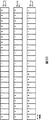
図2は、クラスタップ取得部21が取得するクラスタップを説明する図である。クラスタップ取得部21は、図2に示すように、所定の位置の11個のクラスタップを取得する。
【0009】
波形分類部22は、クラスタップを基に、注目画素を複数のクラスのうちの1つのクラスに分類し、分類されたクラスに対応するクラス番号を予測タップ取得部15に供給する。波形分類部22は、11個のクラスタップを基に、注目画素を、2048のクラスのうちの1つのクラスに分類する。
【0010】
予測タップ取得部15は、クラス番号を基に、フレームメモリ13から分類されたクラスに対応する、SD画像の画素である、所定の数の予測タップを取得し、取得した予測タップおよびクラス番号を対応画素取得部16に供給する。
【0011】
図3は、予測タップ取得部15が取得する予測タップを説明する図である。予測タップ取得部15は、図3に示すように、所定の位置の9個の予測タップを取得する。
【0012】
対応画素取得部16は、予測タップおよびクラス番号を基に、フレームメモリ11から、予測すべき画素値に対応するHD画像の画素を取得し、予測タップ、クラス番号、および取得した予測すべき画素値に対応するHD画像の画素を正規方程式生成部17に供給する。
【0013】
正規方程式生成部17は、予測タップ、クラス番号、および取得した予測すべき画素値を基に、各クラスに対応し、予測タップおよび予測すべき画素値の関係に対応する正規方程式を生成し、各クラスに対応する、生成した正規方程式を係数計算部18に供給する。
【0014】
係数計算部18は、正規方程式生成部17から供給された正規方程式を解いて、各クラスに対応する係数セットを計算し、クラス番号と共に、計算した係数セットを係数セットメモリ19に供給する。
【0015】
係数セットメモリ19は、クラス番号を基に、算出された係数セットをクラスに対応させて記憶する。
【0016】
図4は、クラス分類適応処理の概略を説明する図である。クラス分類適応処理において、HD画像である教師画像から、4分の1加重平均の処理により、対応するSD画像を生成する。生成されたSD画像は、生徒画像と称する。
【0017】
次に、HD画像である教師画像、および対応するSD画像である生徒画像を基に、SD画像からHD画像を生成するための係数セットが生成される。係数セットは、線形予測などにより、SD画像からHD画像を生成するための係数で構成される。
【0018】
このように生成された係数セットおよびSD画像から、線形予測などにより、4倍密画像が生成される。係数セットおよび入力画像から、より高密度な画像などを生成する処理をマッピングとも称する。
【0019】
生成された4倍密画像、および対応するHD画像を基に、SNRの比較、または目視による定性評価が行われる。
【0020】
特定の教師画像、および対応する生徒画像から生成された係数セットは、特定の教師画像、および対応する生徒画像のセルフの係数セットと称する。セルフの係数セットを使用したマッピングは、セルフマッピングと称する。複数の他の教師画像、および対応する生徒画像から生成された係数セットは、クロスの係数セットと称する。
【0021】
一方、静止している所定の背景の前で移動する前景である物体をビデオカメラで撮像して得られる画像には、物体の移動速度が比較的速い場合、動きボケが生じ、背景と前景の混ざり合いが生ずる。
【0022】
従来のクラス分類適応処理においては、図5に示すように、前景、背景、並びに前景および背景の混ざり合いが生じている部分の全てに対して、以上のような学習の処理により、1つの係数セットが生成され、この係数セットを基に、マッピングの処理が実行される。
【0023】
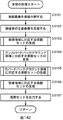
図6のフローチャートを参照して、SD画像からHD画像を生成する処理において使用される係数を生成する、従来の学習の処理を説明する。ステップS11において、画像処理装置は、生徒画像に未処理の画素があるか否かを判定し、生徒画像に未処理の画素があると判定された場合、ステップS12に進み、ラスタースキャン順に、生徒画像から注目画素を取得する。
【0024】
ステップS13において、クラス分類部14のクラスタップ取得部21は、フレームメモリ13に記憶されている生徒画像から、注目画素に対応するクラスタップを取得する。ステップS14において、クラス分類部14の波形分類部22は、クラスタップを基に、注目画素をクラス分類する。ステップS15において、予測タップ取得部15は、分類されたクラスを基に、フレームメモリ13に記憶されている生徒画像から、注目画素に対応する予測タップを取得する。
【0025】
ステップS16において、対応画素取得部16は、分類されたクラスを基に、フレームメモリ11に記憶されている教師画像から、予測すべき画素値に対応する画素を取得する。
【0026】
ステップS17において、正規方程式生成部17は、分類されたクラスを基に、クラス毎の行列に、予測タップおよび予測すべき画素値に対応する画素の画素値を足し込み、ステップS11に戻り、画像処理装置は、未処理の画素があるか否かの判定を繰り返す。予測タップおよび予測すべき画素値に対応する画素の画素値を足し込まれるクラス毎の行列は、クラス毎の係数を計算するための正規方程式に対応する。
【0027】
ステップS11において、生徒画像に未処理の画素がないと判定された場合、ステップS18に進み、正規方程式生成部17は、予測タップおよび予測すべき画素値に対応する画素の画素値が設定された、クラス毎の行列を係数計算部18に供給する。係数計算部18は、予測タップおよび予測すべき画素値に対応する画素の画素値が設定された、クラス毎の行列を解いて、クラス毎の係数セットを計算する。
【0028】
ステップS19において、係数計算部18は、計算されたクラス毎の係数を係数セットメモリ19に出力する。係数セットメモリ19は、クラス毎に係数セットを記憶し、処理は終了する。
【0029】
図7は、クラス分類適応処理により、SD画像からHD画像を生成する従来の画像処理装置の構成を示すブロック図である。
【0030】
フレームメモリ31は、SD画像である入力画像を、フレーム単位で記憶する。
フレームメモリ31は、記憶しているSD画像をマッピング部32に供給する。
【0031】
マッピング部32に入力されたSD画像は、クラス分類部41および予測タップ取得部42に供給される。
【0032】
クラス分類部41は、クラスタップ取得部51および波形分類部52で構成され、フレームメモリ31に記憶されているSD画像の、注目している画素である、注目画素をクラス分類する。クラスタップ取得部51は、フレームメモリ31から注目画素に対応する、所定の数のクラスタップを取得し、取得したクラスタップを波形分類部52に供給する。
【0033】
波形分類部52は、クラスタップを基に、所定の数のクラスのうちの、1つのクラスに注目画素を分類し、分類されたクラスに対応するクラス番号を予測タップ取得部42に供給する。
【0034】
予測タップ取得部42は、クラス番号を基に、フレームメモリ31に記憶されている入力画像から、分類されたクラスに対応する、所定の数の予測タップを取得し、取得した予測タップおよびクラス番号を予測演算部43に供給する。
【0035】
予測演算部43は、クラス番号を基に、係数セットメモリ33に記憶されている係数セットから、クラスに対応する係数セットを取得する。予測演算部43は、クラスに対応する係数セット、および予測タップを基に、線形予測により予測画像の画素値を予測する。予測演算部43は、予測した画素値をフレームメモリ34に供給する。
【0036】
フレームメモリ34は、予測演算部43から供給された予測された画素値を記憶し、予測された画素値が設定されたHD画像を出力する。
【0037】
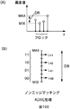
図8は、入力画像の画素値、およびクラス分類適応処理により生成された出力画像の画素値を示す図である。図8に示すように、クラス分類適応処理により生成される画像は、SD画像の帯域制限で失われた波形を含む。その意味で、クラス分類適応処理による、より高解像度の画像の生成の処理は、解像度を創造していると言える。
【0038】
図9のフローチャートを参照して、クラス分類適応処理を実行する画像処理装置による、SD画像からHD画像を生成する、従来の画像の創造の処理を説明する。
【0039】
ステップS31において、画像処理装置は、入力画像に未処理の画素があるか否かを判定し、入力画像に未処理の画素があると判定された場合、ステップS32に進み、マッピング部32は、係数セットメモリ33に記憶されている係数セットを取得する。ステップS33において、画像処理装置は、ラスタースキャン順に、入力画像から注目画素を取得する。
【0040】
ステップS34において、クラス分類部41のクラスタップ取得部51は、フレームメモリ31に記憶されている入力画像から、注目画素に対応するクラスタップを取得する。ステップS35において、クラス分類部41の波形分類部52は、クラスタップを基に、注目画素を1つのクラスにクラス分類する。
【0041】
ステップS36において、予測タップ取得部42は、分類されたクラスを基に、フレームメモリ31に記憶されている入力画像から、注目画素に対応する予測タップを取得する。
【0042】
ステップS37において、予測演算部43は、分類されたクラスに対応する係数セット、および予測タップを基に、線形予測により、予測画像の画素値を予測する。
【0043】
ステップS38において、予測演算部43は、予測された画素値をフレームメモリ34に出力する。フレームメモリ34は、予測演算部43から供給された画素値を記憶する。手続きは、ステップS31に戻り、未処理の画素があるか否かの判定を繰り返す。
【0044】
ステップS31において、入力画像に未処理の画素がないと判定された場合、ステップS39に進み、フレームメモリ34は、予測値が設定された、記憶している予測画像を出力して、処理は終了する。
【0045】
【発明が解決しようとする課題】
静止している背景の前で物体が移動するとき、移動する物体の画像自身の混ざり合いによる動きボケのみならず、背景の画像と移動する物体の画像との混ざり合いが生じる。従来、背景の画像と移動する物体の画像との混ざり合いに対応して画像を処理することは、考えられていなかった。
【0046】
本発明はこのような状況に鑑みてなされたものであり、背景の画像と移動する物体の画像との混ざり合いに対応して画像を処理することができるようにすることを目的とする。
【0047】
【課題を解決するための手段】
本発明の画像処理装置は、時間積分効果を有する所定数の画素を有する撮像素子によって取得された所定数の画素からなる入力画像を処理する画像処理装置において、入力画像とその1つ前及び後に取得された入力画像との間で、同じ位置の画素の画素値の差分の絶対値と予め定められた閾値とを比較することで、入力画像とその1つ前の入力画像との間の画素の動きの有無及び入力画像とその1つ後の入力画像との間の画素の動きの有無を判定し、その判定結果に基づいて、入力画像の、前景オブジェクトを構成する前景オブジェクト成分からなる前景領域と、背景オブジェクトを構成する背景オブジェクト成分からなる背景領域を少なくとも特定し、特定結果を示す領域特定情報を出力する領域特定手段と、学習用データとして入力される入力画像を用いて、前景領域の画像と背景領域の画像のそれぞれについて、入力画像を教師画像とし、入力画像を低解像度にした画像を生徒画像として、教師画像の所定の画素を、それに対応する生徒画像の画素周辺の複数の画素と予測係数の線形1次式で表し、線形1次式で表される予測画素値と教師画像の所定の画素の画素値との誤差が最小となるような予測係数を予め求める予測係数生成手段と、予測処理用データとして入力される入力画像の前景領域の画像と背景領域の画像のそれぞれについて、予め求めた予測係数と入力画像の画素周辺の複数の画素との線形1次式を演算することにより、入力画像の前景領域の画像と背景領域の画像を高解像度の出力画像に変換する変換手段とを含むことを特徴とする。
【0048】
領域特定手段には、入力画像の1つ前と2つ前及び1つ後と2つ後に取得された入力画像との間の画素の動きの有無の判定結果も用いて、前景オブジェクト成分と背景オブジェクト成分が混合されてなる混合領域のうちの、時間の経過に対応して背景オブジェクト成分から前景オブジェクト成分になる領域であるカバードバックグラウンド領域と、時間の経過に対応して前景オブジェクト成分から背景オブジェクト成分になる領域であるアンカバードバックグラウンド領域をさらに特定させ、予測係数生成手段には、学習用データとして入力される入力画像を用いて、カバードバックグラウンド領域およびアンカバードバックグラウンド領域の画像についても予測係数をそれぞれ予め求めさせ、変換手段には、予測処理用データとして入力される入力画像のカバードバックグラウンド領域およびアンカバードバックグラウンド領域の画像のそれぞれについても、高解像度の出力画像に変換させることができる。
【0049】
予測処理用データとして入力される入力画像の前景領域の画像、背景領域の画像、カバードバックグラウンド領域の画像、およびアンカバードバックグラウンド領域の画像を高解像度に変換してそれぞれ得られた出力画像を合成して出力する合成手段をさらに備えることができる。
【0051】
本発明の画像処理方法は、時間積分効果を有する所定数の画素を有する撮像素子によって取得された所定数の画素からなる入力画像を処理する画像処理方法において、入力画像とその1つ前及び後に取得された入力画像との間で、同じ位置の画素の画素値の差分の絶対値と予め定められた閾値とを比較することで、入力画像とその1つ前の入力画像との間の画素の動きの有無及び入力画像とその1つ後の入力画像との間の画素の動きの有無を判定し、その判定結果に基づいて、入力画像の、前景オブジェクトを構成する前景オブジェクト成分からなる前景領域と、背景オブジェクトを構成する背景オブジェクト成分からなる背景領域を少なくとも特定し、特定結果を示す領域特定情報を出力する領域特定ステップと、学習用データとして入力される入力画像を用いて、前景領域の画像と背景領域の画像のそれぞれについて、入力画像を教師画像とし、入力画像を低解像度にした画像を生徒画像として、教師画像の所定の画素を、それに対応する生徒画像の画素周辺の複数の画素と予測係数の線形1次式で表し、線形1次式で表される予測画素値と教師画像の所定の画素の画素値との誤差が最小となるような予測係数を予め求める予測係数生成ステップと、予測処理用データとして入力される入力画像の前景領域の画像と背景領域の画像のそれぞれについて、予め求めた予測係数と入力画像の画素周辺の複数の画素との線形1次式を演算することにより、入力画像の前景領域の画像と背景領域の画像を高解像度の出力画像に変換する変換ステップとを含むことを特徴とする。
【0055】
本発明の記録媒体は、コンピュータに、時間積分効果を有する所定数の画素を有する撮像素子によって取得された所定数の画素からなる入力画像とその1つ前及び後に取得された入力画像との間で、同じ位置の画素の画素値の差分の絶対値と予め定められた閾値とを比較することで、入力画像とその1つ前の入力画像との間の画素の動きの有無及び入力画像とその1つ後の入力画像との間の画素の動きの有無を判定し、その判定結果に基づいて、入力画像の、前景オブジェクトを構成する前景オブジェクト成分からなる前景領域と、背景オブジェクトを構成する背景オブジェクト成分からなる背景領域を少なくとも特定し、特定結果を示す領域特定情報を出力する領域特定ステップと、学習用データとして入力される入力画像を用いて、前景領域の画像と背景領域の画像のそれぞれについて、入力画像を教師画像とし、入力画像を低解像度にした画像を生徒画像として、教師画像の所定の画素を、それに対応する生徒画像の画素周辺の複数の画素と予測係数の線形1次式で表し、線形1次式で表される予測画素値と教師画像の所定の画素の画素値との誤差が最小となるような予測係数を予め求める予測係数生成ステップと、予測処理用データとして入力される入力画像の前景領域の画像と背景領域の画像のそれぞれについて、予め求めた予測係数と入力画像の画素周辺の複数の画素との線形1次式を演算することにより、入力画像の前景領域の画像と背景領域の画像を高解像度の出力画像に変換する変換ステップとを実行させるためのプログラムを記録したコンピュータ読み取り可能なものである。
【0059】
本発明のプログラムは、時間積分効果を有する所定数の画素を有する撮像素子によって取得された所定数の画素からなる入力画像を処理させるコンピュータに、入力画像とその1つ前及び後に取得された入力画像との間で、同じ位置の画素の画素値の差分の絶対値と予め定められた閾値とを比較することで、入力画像とその1つ前の入力画像との間の画素の動きの有無及び入力画像とその1つ後の入力画像との間の画素の動きの有無を判定し、その判定結果に基づいて、入力画像の、前景オブジェクトを構成する前景オブジェクト成分からなる前景領域と、背景オブジェクトを構成する背景オブジェクト成分からなる背景領域を少なくとも特定し、特定結果を示す領域特定情報を出力する領域特定ステップと、学習用データとして入力される入力画像を用いて、前景領域の画像と背景領域の画像のそれぞれについて、入力画像を教師画像とし、入力画像を低解像度にした画像を生徒画像として、教師画像の所定の画素を、それに対応する生徒画像の画素周辺の複数の画素と予測係数の線形1次式で表し、線形1次式で表される予測画素値と教師画像の所定の画素の画素値との誤差が最小となるような予測係数を予め求める予測係数生成ステップと、予測処理用データとして入力される入力画像の前景領域の画像と背景領域の画像のそれぞれについて、予め求めた予測係数と入力画像の画素周辺の複数の画素との線形1次式を演算することにより、入力画像の前景領域の画像と背景領域の画像を高解像度の出力画像に変換する変換ステップとを実行させるためのものである。
【0063】
本発明の画像処理装置および方法、記録媒体、並びにプログラムにおいては、入力画像とその1つ前及び後に取得された入力画像との間で、同じ位置の画素の画素値の差分の絶対値と予め定められた閾値とを比較することで、入力画像とその1つ前の入力画像との間の画素の動きの有無及び入力画像とその1つ後の入力画像との間の画素の動きの有無が判定され、その判定結果に基づいて、入力画像の、前景オブジェクトを構成する前景オブジェクト成分からなる前景領域と、背景オブジェクトを構成する背景オブジェクト成分からなる背景領域が少なくとも特定され、特定結果を示す領域特定情報が出力され、学習用データとして入力される入力画像を用いて、前景領域の画像と背景領域の画像のそれぞれについて、入力画像を教師画像とし、入力画像を低解像度にした画像を生徒画像として、教師画像の所定の画素を、それに対応する生徒画像の画素周辺の複数の画素と予測係数の線形1次式で表し、線形1次式で表される予測画素値と教師画像の所定の画素の画素値との誤差が最小となるような予測係数が予め求められ、予測処理用データとして入力される入力画像の前景領域の画像と背景領域の画像のそれぞれについて、予め求めた予測係数と入力画像の画素周辺の複数の画素との線形1次式を演算することにより、入力画像の前景領域の画像と背景領域の画像が高解像度の出力画像に変換される。
【0064】
【発明の実施の形態】
図10は、本発明に係る画像処理装置の一実施の形態の構成を示すブロック図である。CPU(Central Processing Unit)71は、ROM(Read Only Memory)72、または記憶部78に記憶されているプログラムに従って各種の処理を実行する。RAM(Random Access Memory)73には、CPU71が実行するプログラムやデータなどが適宜記憶される。これらのCPU71、ROM72、およびRAM73は、バス74により相互に接続されている。
【0065】
CPU71にはまた、バス74を介して入出力インタフェース75が接続されている。入出力インタフェース75には、キーボード、マウス、マイクロホンなどよりなる入力部76、ディスプレイ、スピーカなどよりなる出力部77が接続されている。CPU71は、入力部76から入力される指令に対応して各種の処理を実行する。そして、CPU71は、処理の結果得られた画像や音声等を出力部77に出力する。
【0066】
入出力インタフェース75に接続されている記憶部78は、例えばハードディスクなどで構成され、CPU71が実行するプログラムや各種のデータを記憶する。通信部79は、インターネット、その他のネットワークを介して外部の装置と通信する。この例の場合、通信部79はセンサの出力を取り込む取得部として働く。
【0067】
また、通信部79を介してプログラムを取得し、記憶部78に記憶してもよい。
【0068】
入出力インタフェース75に接続されているドライブ80は、磁気ディスク91、光ディスク92、光磁気ディスク93、または半導体メモリ94などが装着されたとき、それらを駆動し、そこに記録されているプログラムやデータなどを取得する。取得されたプログラムやデータは、必要に応じて記憶部78に転送され、記憶される。
【0069】
図11は、本発明に係る画像処理装置の機能の構成を示すブロック図である。
【0070】
なお、画像処理装置の各機能をハードウェアで実現するか、ソフトウェアで実現するかは問わない。つまり、本明細書の各ブロック図は、ハードウェアのブロック図と考えても、ソフトウェアによる機能ブロック図と考えても良い。
【0071】
ここで、動きボケとは、撮像の対象となる、現実世界におけるオブジェクトの動きと、センサの撮像の特性とにより生じる、動いているオブジェクトに対応する画像に含まれている歪みをいう。
【0072】
この明細書では、撮像の対象となる、現実世界におけるオブジェクトに対応する画像を、画像オブジェクトと称する。
【0073】
画像処理装置に供給された入力画像は、オブジェクト抽出部101、領域特定部103、混合比算出部104、および前景背景分離部105に供給される。
【0074】
オブジェクト抽出部101は、入力画像に含まれる前景のオブジェクトに対応する画像オブジェクトを粗く抽出して、抽出した画像オブジェクトを動き検出部102に供給する。オブジェクト抽出部101は、例えば、入力画像に含まれる前景のオブジェクトに対応する画像オブジェクトの輪郭を検出することで、前景のオブジェクトに対応する画像オブジェクトを粗く抽出する。
【0075】
オブジェクト抽出部101は、入力画像に含まれる背景のオブジェクトに対応する画像オブジェクトを粗く抽出して、抽出した画像オブジェクトを動き検出部102に供給する。オブジェクト抽出部101は、例えば、入力画像と、抽出された前景のオブジェクトに対応する画像オブジェクトとの差から、背景のオブジェクトに対応する画像オブジェクトを粗く抽出する。
【0076】
また、例えば、オブジェクト抽出部101は、内部に設けられている背景メモリに記憶されている背景の画像と、入力画像との差から、前景のオブジェクトに対応する画像オブジェクト、および背景のオブジェクトに対応する画像オブジェクトを粗く抽出するようにしてもよい。
【0077】
動き検出部102は、例えば、ブロックマッチング法、勾配法、位相相関法、およびペルリカーシブ法などの手法により、粗く抽出された前景のオブジェクトに対応する画像オブジェクトの動きベクトルを算出して、算出した動きベクトルおよび動きベクトルの位置情報(動きベクトルに対応する画素の位置を特定する情報)を領域特定部103および動きボケ除去部106に供給する。
【0078】
動き検出部102が出力する動きベクトルには、動き量vに対応する情報が含まれている。
【0079】
また、例えば、動き検出部102は、画像オブジェクトに画素を特定する画素位置情報と共に、画像オブジェクト毎の動きベクトルを動きボケ除去部106に出力するようにしてもよい。
【0080】
動き量vは、動いているオブジェクトに対応する画像の位置の変化を画素間隔を単位として表す値である。例えば、前景に対応するオブジェクトの画像が、あるフレームを基準として次のフレームにおいて4画素分離れた位置に表示されるように移動しているとき、前景に対応するオブジェクトの画像の動き量vは、4とされる。
【0081】
領域特定部103は、入力された画像の画素のそれぞれを、前景領域、背景領域、または混合領域のいずれかに特定し、画素毎に前景領域、背景領域、または混合領域のいずれかに属するかを示す情報(以下、領域情報と称する)を混合比算出部104、前景背景分離部105、および動きボケ除去部106に供給する。前景領域、背景領域、または混合領域の詳細は、後述する。
【0082】
混合比算出部104は、入力画像、および領域特定部103から供給された領域情報を基に、混合領域に含まれる画素に対応する混合比(以下、混合比αと称する)を算出して、算出した混合比を前景背景分離部105に供給する。
【0083】
混合比αは、後述する式(3)に示されるように、画素値における、背景のオブジェクトに対応する画像の成分(以下、背景の成分とも称する)の割合を示す値である。
【0084】
前景背景分離部105は、領域特定部103から供給された領域情報、および混合比算出部104から供給された混合比αを基に、前景のオブジェクトに対応する画像の成分(以下、前景の成分とも称する)のみから成る前景成分画像と、背景の成分のみから成る背景成分画像とに入力画像を分離して、前景成分画像を動きボケ除去部106に供給し、背景成分画像を補正部107に供給する。
【0085】
動きボケ除去部106は、動きベクトルからわかる動き量vおよび領域情報を基に、前景成分画像に含まれる1以上の画素を示す処理単位を決定する。処理単位は、動きボケの量の調整の処理の対象となる1群の画素を指定するデータである。
【0086】
動きボケ除去部106は、前景背景分離部105から供給された前景成分画像、動き検出部102から供給された動きベクトルおよびその位置情報、並びに処理単位を基に、前景成分画像に含まれる動きボケを除去して、動きボケを除去した前景成分画像を動きボケ除去画像処理部108に出力する。
【0087】
補正部107は、背景成分画像における、混合領域に対応する画素の画素値を補正する。背景成分画像の混合領域に対応する画素の画素値は、分離される前の混合領域の画素の画素値から、前景の成分が除去されることにより、算出される。従って、背景成分画像の混合領域に対応する画素の画素値は、隣接する背景領域の画素の画素値に比較し、混合比αに対応して、減少している。
【0088】
補正部107は、このような、背景成分画像における、混合領域に対応する画素の画素値の混合比αに対応するゲインの低下を補正し、補正した背景成分画像を動きボケ除去画像処理部108に供給する。
【0089】
動きボケ除去画像処理部108は、クラス分類適応処理により、動きボケが除去された前景成分画像、および補正された背景成分画像を個々に処理する。
【0090】
例えば、動きボケ除去画像処理部108は、動きボケが除去された前景成分画像、および補正された背景成分画像毎に、より高解像度の画像を生成するクラス分類適応処理で使用される係数を生成する。
【0091】
例えば、動きボケ除去画像処理部108は、動きボケが除去された前景成分画像、および補正された背景成分画像毎にクラス分類適応処理を適用して、より高解像度の画像を創造する。
【0092】
次に、図12乃至図27を参照して、画像処理装置に供給される入力画像について説明する。
【0093】
図12は、センサによる撮像を説明する図である。センサは、例えば、固体撮像素子であるCCD(Charge-Coupled Device)エリアセンサを備えたCCDビデオカメラなどで構成される。現実世界における、前景に対応するオブジェクトは、現実世界における、背景に対応するオブジェクトと、センサとの間を、例えば、図中の左側から右側に水平に移動する。
【0094】
センサは、前景に対応するオブジェクトを、背景に対応するオブジェクトと共に撮像する。センサは、撮像した画像を1フレーム単位で出力する。例えば、センサは、1秒間に30フレームから成る画像を出力する。センサの露光時間は、1/30秒とすることができる。露光時間は、センサが入力された光の電荷への変換を開始してから、入力された光の電荷への変換を終了するまでの期間である。以下、露光時間をシャッタ時間とも称する。
【0095】
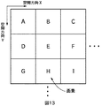
図13は、画素の配置を説明する図である。図13中において、A乃至Iは、個々の画素を示す。画素は、画像に対応する平面上に配置されている。1つの画素に対応する1つの検出素子は、センサ上に配置されている。センサが画像を撮像するとき、1つの検出素子は、画像を構成する1つの画素に対応する画素値を出力する。例えば、検出素子のX方向の位置は、画像上の横方向の位置に対応し、検出素子のY方向の位置は、画像上の縦方向の位置に対応する。
【0096】
図14に示すように、例えば、CCDである検出素子は、シャッタ時間に対応する期間、入力された光を電荷に変換して、変換された電荷を蓄積する。電荷の量は、入力された光の強さと、光が入力されている時間にほぼ比例する。検出素子は、シャッタ時間に対応する期間において、入力された光から変換された電荷を、既に蓄積されている電荷に加えていく。すなわち、検出素子は、シャッタ時間に対応する期間、入力される光を積分して、積分された光に対応する量の電荷を蓄積する。検出素子は、時間に対して、積分効果があるとも言える。
【0097】
検出素子に蓄積された電荷は、図示せぬ回路により、電圧値に変換され、電圧値は更にデジタルデータなどの画素値に変換されて出力される。従って、センサから出力される個々の画素値は、前景または背景に対応するオブジェクトの空間的に広がりを有するある部分を、シャッタ時間について積分した結果である、1次元の空間に射影された値を有する。
【0098】
画像処理装置は、このようなセンサの蓄積の動作により、出力信号に埋もれてしまった有意な情報、例えば、混合比αを抽出する。
【0099】
図15は、動いている前景に対応するオブジェクトと、静止している背景に対応するオブジェクトとを撮像して得られる画像を説明する図である。図15(A)は、動きを伴う前景に対応するオブジェクトと、静止している背景に対応するオブジェクトとを撮像して得られる画像を示している。図15(A)に示す例において、前景に対応するオブジェクトは、画面に対して水平に左から右に動いている。
【0100】
図15(B)は、図15(A)に示す画像の1つのラインに対応する画素値を時間方向に展開したモデル図である。図15(B)の横方向は、図15(A)の空間方向Xに対応している。
【0101】
背景領域の画素は、背景の成分、すなわち、背景のオブジェクトに対応する画像の成分のみから、その画素値が構成されている。前景領域の画素は、前景の成分、すなわち、前景のオブジェクトに対応する画像の成分のみから、その画素値が構成されている。
【0102】
混合領域の画素は、背景の成分、および前景の成分から、その画素値が構成されている。混合領域は、背景の成分、および前景の成分から、その画素値が構成されているので、歪み領域ともいえる。混合領域は、更に、カバードバックグラウンド領域およびアンカバードバックグラウンド領域に分類される。
【0103】
カバードバックグラウンド領域は、前景領域に対して、前景のオブジェクトの進行方向の前端部に対応する位置の混合領域であり、時間の経過に対応して背景成分が前景に覆い隠される領域をいう。
【0104】
これに対して、アンカバードバックグラウンド領域は、前景領域に対して、前景のオブジェクトの進行方向の後端部に対応する位置の混合領域であり、時間の経過に対応して背景成分が現れる領域をいう。
【0105】
このように、前景領域、背景領域、またはカバードバックグラウンド領域若しくはアンカバードバックグラウンド領域を含む画像が、領域特定部103、混合比算出部104、および前景背景分離部105に入力画像として入力される。
【0106】
図16は、以上のような、背景領域、前景領域、混合領域、カバードバックグラウンド領域、およびアンカバードバックグラウンド領域を説明する図である。図15に示す画像に対応する場合、背景領域は、静止部分であり、前景領域は、動き部分であり、混合領域のカバードバックグラウンド領域は、背景から前景に変化する部分であり、混合領域のアンカバードバックグラウンド領域は、前景から背景に変化する部分である。
【0107】
図17は、静止している前景に対応するオブジェクトおよび静止している背景に対応するオブジェクトを撮像した画像における、隣接して1列に並んでいる画素の画素値を時間方向に展開したモデル図である。例えば、隣接して1列に並んでいる画素として、画面の1つのライン上に並んでいる画素を選択することができる。
【0108】
図17に示すF01乃至F04の画素値は、静止している前景のオブジェクトに対応する画素の画素値である。図17に示すB01乃至B04の画素値は、静止している背景のオブジェクトに対応する画素の画素値である。
【0109】
図17における縦方向は、図中の上から下に向かって時間が経過する。図17中の矩形の上辺の位置は、センサが入力された光の電荷への変換を開始する時刻に対応し、図17中の矩形の下辺の位置は、センサが入力された光の電荷への変換を終了する時刻に対応する。すなわち、図17中の矩形の上辺から下辺までの距離は、シャッタ時間に対応する。
【0110】
以下において、シャッタ時間とフレーム間隔とが同一である場合を例に説明する。
【0111】
図17における横方向は、図15で説明した空間方向Xに対応する。より具体的には、図17に示す例において、図17中の”F01”と記載された矩形の左辺から”B04”と記載された矩形の右辺までの距離は、画素のピッチの8倍、すなわち、連続している8つの画素の間隔に対応する。
【0112】
前景のオブジェクトおよび背景のオブジェクトが静止している場合、シャッタ時間に対応する期間において、センサに入力される光は変化しない。
【0113】
ここで、シャッタ時間に対応する期間を2つ以上の同じ長さの期間に分割する。例えば、仮想分割数を4とすると、図17に示すモデル図は、図18に示すモデルとして表すことができる。仮想分割数は、前景に対応するオブジェクトのシャッタ時間内での動き量vなどに対応して設定される。例えば、4である動き量vに対応して、仮想分割数は、4とされ、シャッタ時間に対応する期間は4つに分割される。
【0114】
図中の最も上の行は、シャッタが開いて最初の、分割された期間に対応する。
図中の上から2番目の行は、シャッタが開いて2番目の、分割された期間に対応する。図中の上から3番目の行は、シャッタが開いて3番目の、分割された期間に対応する。図中の上から4番目の行は、シャッタが開いて4番目の、分割された期間に対応する。
【0115】
以下、動き量vに対応して分割されたシャッタ時間をシャッタ時間/vとも称する。
【0116】
前景に対応するオブジェクトが静止しているとき、センサに入力される光は変化しないので、前景の成分F01/vは、画素値F01を仮想分割数で除した値に等しい。同様に、前景に対応するオブジェクトが静止しているとき、前景の成分F02/vは、画素値F02を仮想分割数で除した値に等しく、前景の成分F03/vは、画素値F03を仮想分割数で除した値に等しく、前景の成分F04/vは、画素値F04を仮想分割数で除した値に等しい。
【0117】
背景に対応するオブジェクトが静止しているとき、センサに入力される光は変化しないので、背景の成分B01/vは、画素値B01を仮想分割数で除した値に等しい。同様に、背景に対応するオブジェクトが静止しているとき、背景の成分B02/vは、画素値B02を仮想分割数で除した値に等しく、B03/vは、画素値B03を仮想分割数で除した値に等しく、B04/vは、画素値B04を仮想分割数で除した値に等しい。
【0118】
すなわち、前景に対応するオブジェクトが静止している場合、シャッタ時間に対応する期間において、センサに入力される前景のオブジェクトに対応する光が変化しないので、シャッタが開いて最初の、シャッタ時間/vに対応する前景の成分F01/vと、シャッタが開いて2番目の、シャッタ時間/vに対応する前景の成分F01/vと、シャッタが開いて3番目の、シャッタ時間/vに対応する前景の成分F01/vと、シャッタが開いて4番目の、シャッタ時間/vに対応する前景の成分F01/vとは、同じ値となる。F02/v乃至F04/vも、F01/vと同様の関係を有する。
【0119】
背景に対応するオブジェクトが静止している場合、シャッタ時間に対応する期間において、センサに入力される背景のオブジェクトに対応する光は変化しないので、シャッタが開いて最初の、シャッタ時間/vに対応する背景の成分B01/vと、シャッタが開いて2番目の、シャッタ時間/vに対応する背景の成分B01/vと、シャッタが開いて3番目の、シャッタ時間/vに対応する背景の成分B01/vと、シャッタが開いて4番目の、シャッタ時間/vに対応する背景の成分B01/vとは、同じ値となる。B02/v乃至B04/vも、同様の関係を有する。
【0120】
次に、前景に対応するオブジェクトが移動し、背景に対応するオブジェクトが静止している場合について説明する。
【0121】
図19は、前景に対応するオブジェクトが図中の右側に向かって移動する場合の、カバードバックグラウンド領域を含む、1つのライン上の画素の画素値を時間方向に展開したモデル図である。図19において、前景の動き量vは、4である。1フレームは短い時間なので、前景に対応するオブジェクトが剛体であり、等速で移動していると仮定することができる。図19において、前景に対応するオブジェクトの画像は、あるフレームを基準として次のフレームにおいて4画素分右側に表示されるように移動する。
【0122】
図19において、最も左側の画素乃至左から4番目の画素は、前景領域に属する。図19において、左から5番目乃至左から7番目の画素は、カバードバックグラウンド領域である混合領域に属する。図19において、最も右側の画素は、背景領域に属する。
【0123】
前景に対応するオブジェクトが時間の経過と共に背景に対応するオブジェクトを覆い隠すように移動しているので、カバードバックグラウンド領域に属する画素の画素値に含まれる成分は、シャッタ時間に対応する期間のある時点で、背景の成分から、前景の成分に替わる。
【0124】
例えば、図19中に太線枠を付した画素値Mは、式(1)で表される。
【0125】
M=B02/v+B02/v+F07/v+F06/v (1)
【0126】
例えば、左から5番目の画素は、1つのシャッタ時間/vに対応する背景の成分を含み、3つのシャッタ時間/vに対応する前景の成分を含むので、左から5番目の画素の混合比αは、1/4である。左から6番目の画素は、2つのシャッタ時間/vに対応する背景の成分を含み、2つのシャッタ時間/vに対応する前景の成分を含むので、左から6番目の画素の混合比αは、1/2である。左から7番目の画素は、3つのシャッタ時間/vに対応する背景の成分を含み、1つのシャッタ時間/vに対応する前景の成分を含むので、左から7番目の画素の混合比αは、3/4である。
【0127】
前景に対応するオブジェクトが、剛体であり、前景の画像が次のフレームにおいて4画素右側に表示されるように等速で移動すると仮定できるので、例えば、図19中の左から4番目の画素の、シャッタが開いて最初の、シャッタ時間/vの前景の成分F07/vは、図19中の左から5番目の画素の、シャッタが開いて2番目のシャッタ時間/vに対応する前景の成分に等しい。同様に、前景の成分F07/vは、図19中の左から6番目の画素の、シャッタが開いて3番目のシャッタ時間/vに対応する前景の成分と、図19中の左から7番目の画素の、シャッタが開いて4番目のシャッタ時間/vに対応する前景の成分とに、それぞれ等しい。
【0128】
前景に対応するオブジェクトが、剛体であり、前景の画像が次のフレームにおいて4画素右側に表示されるように等速で移動すると仮定できるので、例えば、図19中の左から3番目の画素の、シャッタが開いて最初のシャッタ時間/vの前景の成分F06/vは、図19中の左から4番目の画素の、シャッタが開いて2番目のシャッタ時間/vに対応する前景の成分に等しい。同様に、前景の成分F06/vは、図19中の左から5番目の画素の、シャッタが開いて3番目のシャッタ時間/vに対応する前景の成分と、図19中の左から6番目の画素の、シャッタが開いて4番目のシャッタ時間/vに対応する前景の成分とに、それぞれ等しい。
【0129】
前景に対応するオブジェクトが、剛体であり、前景の画像が次のフレームにおいて4画素右側に表示されるように等速で移動すると仮定できるので、例えば、図19中の左から2番目の画素の、シャッタが開いて最初のシャッタ時間/vの前景の成分F05/vは、図19中の左から3番目の画素の、シャッタが開いて2番目のシャッタ時間/vのに対応する前景の成分に等しい。同様に、前景の成分F05/vは、図19中の左から4番目の画素の、シャッタが開いて3番目のシャッタ時間/vに対応する前景の成分と、図19中の左から5番目の画素の、シャッタが開いて4番目のシャッタ時間/vに対応する前景の成分とに、それぞれ等しい。
【0130】
前景に対応するオブジェクトが、剛体であり、前景の画像が次のフレームにおいて4画素右側に表示されるように等速で移動すると仮定できるので、例えば、図19中の最も左側の画素の、シャッタが開いて最初のシャッタ時間/vの前景の成分F04/vは、図19中の左から2番目の画素の、シャッタが開いて2番目のシャッタ時間/vに対応する前景の成分に等しい。同様に、前景の成分F04/vは、図19中の左から3番目の画素の、シャッタが開いて3番目のシャッタ時間/vに対応する前景の成分と、図19中の左から4番目の画素の、シャッタが開いて4番目のシャッタ時間/vに対応する前景の成分とに、それぞれ等しい。
【0131】
動いているオブジェクトに対応する前景の領域は、このように動きボケを含むので、歪み領域とも言える。
【0132】
図20は、前景が図中の右側に向かって移動する場合の、アンカバードバックグラウンド領域を含む、1つのライン上の画素の画素値を時間方向に展開したモデル図である。図20において、前景の動き量vは、4である。1フレームは短い時間なので、前景に対応するオブジェクトが剛体であり、等速で移動していると仮定することができる。図20において、前景に対応するオブジェクトの画像は、あるフレームを基準として次のフレームにおいて4画素分右側に移動する。
【0133】
図20において、最も左側の画素乃至左から4番目の画素は、背景領域に属する。図20において、左から5番目乃至左から7番目の画素は、アンカバードバックグラウンドである混合領域に属する。図20において、最も右側の画素は、前景領域に属する。
【0134】
背景に対応するオブジェクトを覆っていた前景に対応するオブジェクトが時間の経過と共に背景に対応するオブジェクトの前から取り除かれるように移動しているので、アンカバードバックグラウンド領域に属する画素の画素値に含まれる成分は、シャッタ時間に対応する期間のある時点で、前景の成分から、背景の成分に替わる。
【0135】
例えば、図20中に太線枠を付した画素値M'は、式(2)で表される。
【0136】
M'=F02/v+F01/v+B26/v+B26/v (2)
【0137】
例えば、左から5番目の画素は、3つのシャッタ時間/vに対応する背景の成分を含み、1つのシャッタ時間/vに対応する前景の成分を含むので、左から5番目の画素の混合比αは、3/4である。左から6番目の画素は、2つのシャッタ時間/vに対応する背景の成分を含み、2つのシャッタ時間/vに対応する前景の成分を含むので、左から6番目の画素の混合比αは、1/2である。左から7番目の画素は、1つのシャッタ時間/vに対応する背景の成分を含み、3つのシャッタ時間/vに対応する前景の成分を含むので、左から7番目の画素の混合比αは、1/4である。
【0138】
式(1)および式(2)をより一般化すると、画素値Mは、式(3)で表される。
【0139】
【数1】

【0140】
前景に対応するオブジェクトが剛体であり、等速で動くと仮定でき、かつ、動き量vが4であるので、例えば、図20中の左から5番目の画素の、シャッタが開いて最初の、シャッタ時間/vの前景の成分F01/vは、図20中の左から6番目の画素の、シャッタが開いて2番目のシャッタ時間/vに対応する前景の成分に等しい。同様に、F01/vは、図20中の左から7番目の画素の、シャッタが開いて3番目のシャッタ時間/vに対応する前景の成分と、図20中の左から8番目の画素の、シャッタが開いて4番目のシャッタ時間/vに対応する前景の成分とに、それぞれ等しい。
【0141】
前景に対応するオブジェクトが剛体であり、等速で動くと仮定でき、かつ、仮想分割数が4であるので、例えば、図20中の左から6番目の画素の、シャッタが開いて最初の、シャッタ時間/vの前景の成分F02/vは、図20中の左から7番目の画素の、シャッタが開いて2番目のシャッタ時間/vに対応する前景の成分に等しい。同様に、前景の成分F02/vは、図20中の左から8番目の画素の、シャッタが開いて3番目のシャッタ時間/vに対応する前景の成分に等しい。
【0142】
前景に対応するオブジェクトが剛体であり、等速で動くと仮定でき、かつ、動き量vが4であるので、例えば、図20中の左から7番目の画素の、シャッタが開いて最初の、シャッタ時間/vの前景の成分F03/vは、図20中の左から8番目の画素の、シャッタが開いて2番目のシャッタ時間/vに対応する前景の成分に等しい。
【0143】
図18乃至図20の説明において、仮想分割数は、4であるとして説明したが、仮想分割数は、動き量vに対応する。動き量vは、一般に、前景に対応するオブジェクトの移動速度に対応する。例えば、前景に対応するオブジェクトが、あるフレームを基準として次のフレームにおいて4画素分右側に表示されるように移動しているとき、動き量vは、4とされる。動き量vに対応し、仮想分割数は、4とされる。同様に、例えば、前景に対応するオブジェクトが、あるフレームを基準として次のフレームにおいて6画素分左側に表示されるように移動しているとき、動き量vは、6とされ、仮想分割数は、6とされる。
【0144】
図21および図22に、以上で説明した、前景領域、背景領域、カバードバックグラウンド領域若しくはアンカバードバックグラウンド領域から成る混合領域と、分割されたシャッタ時間に対応する前景の成分および背景の成分との関係を示す。
【0145】
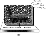
図21は、静止している背景の前を移動しているオブジェクトに対応する前景を含む画像から、前景領域、背景領域、および混合領域の画素を抽出した例を示す。図21に示す例において、前景に対応するオブジェクトは、画面に対して水平に移動している。
【0146】
フレーム#n+1は、フレーム#nの次のフレームであり、フレーム#n+2は、フレーム#n+1の次のフレームである。
【0147】
フレーム#n乃至フレーム#n+2のいずれかから抽出した、前景領域、背景領域、および混合領域の画素を抽出して、動き量vを4として、抽出された画素の画素値を時間方向に展開したモデルを図22に示す。
【0148】
前景領域の画素値は、前景に対応するオブジェクトが移動するので、シャッタ時間/vの期間に対応する、4つの異なる前景の成分から構成される。例えば、図22に示す前景領域の画素のうち最も左側に位置する画素は、F01/v,F02/v,F03/v、およびF04/vから構成される。すなわち、前景領域の画素は、動きボケを含んでいる。
【0149】
背景に対応するオブジェクトが静止しているので、シャッタ時間に対応する期間において、センサに入力される背景に対応する光は変化しない。この場合、背景領域の画素値は、動きボケを含まない。
【0150】
カバードバックグラウンド領域若しくはアンカバードバックグラウンド領域から成る混合領域に属する画素の画素値は、前景の成分と、背景の成分とから構成される。
【0151】
次に、オブジェクトに対応する画像が動いているとき、複数のフレームにおける、隣接して1列に並んでいる画素であって、フレーム上で同一の位置の画素の画素値を時間方向に展開したモデルについて説明する。例えば、オブジェクトに対応する画像が画面に対して水平に動いているとき、隣接して1列に並んでいる画素として、画面の1つのライン上に並んでいる画素を選択することができる。
【0152】
図23は、静止している背景に対応するオブジェクトを撮像した画像の3つのフレームの、隣接して1列に並んでいる画素であって、フレーム上で同一の位置の画素の画素値を時間方向に展開したモデル図である。フレーム#nは、フレーム#n-1の次のフレームであり、フレーム#n+1は、フレーム#nの次のフレームである。他のフレームも同様に称する。
【0153】
図23に示すB01乃至B12の画素値は、静止している背景のオブジェクトに対応する画素の画素値である。背景に対応するオブジェクトが静止しているので、フレーム#n-1乃至フレームn+1において、対応する画素の画素値は、変化しない。例えば、フレーム#n-1におけるB05の画素値を有する画素の位置に対応する、フレーム#nにおける画素、およびフレーム#n+1における画素は、それぞれ、B05の画素値を有する。
【0154】
図24は、静止している背景に対応するオブジェクトと共に図中の右側に移動する前景に対応するオブジェクトを撮像した画像の3つのフレームの、隣接して1列に並んでいる画素であって、フレーム上で同一の位置の画素の画素値を時間方向に展開したモデル図である。図24に示すモデルは、カバードバックグラウンド領域を含む。
【0155】
図24において、前景に対応するオブジェクトが、剛体であり、等速で移動すると仮定でき、前景の画像が次のフレームにおいて4画素右側に表示されるように移動するので、前景の動き量vは、4であり、仮想分割数は、4である。
【0156】
例えば、図24中のフレーム#n-1の最も左側の画素の、シャッタが開いて最初のシャッタ時間/vの前景の成分は、F12/vとなり、図24中の左から2番目の画素の、シャッタが開いて2番目のシャッタ時間/vの前景の成分も、F12/vとなる。図24中の左から3番目の画素の、シャッタが開いて3番目のシャッタ時間/vの前景の成分、および図24中の左から4番目の画素の、シャッタが開いて4番目のシャッタ時間/vの前景の成分は、F12/vとなる。
【0157】
図24中のフレーム#n-1の最も左側の画素の、シャッタが開いて2番目のシャッタ時間/vの前景の成分は、F11/vとなり、図24中の左から2番目の画素の、シャッタが開いて3番目のシャッタ時間/vの前景の成分も、F11/vとなる。図24中の左から3番目の画素の、シャッタが開いて4番目のシャッタ時間/vの前景の成分は、F11/vとなる。
【0158】
図24中のフレーム#n-1の最も左側の画素の、シャッタが開いて3番目のシャッタ時間/vの前景の成分は、F10/vとなり、図24中の左から2番目の画素の、シャッタが開いて4番目のシャッタ時間/vの前景の成分も、F10/vとなる。図24中のフレーム#n-1の最も左側の画素の、シャッタが開いて4番目のシャッタ時間/vの前景の成分は、F09/vとなる。
【0159】
背景に対応するオブジェクトが静止しているので、図24中のフレーム#n-1の左から2番目の画素の、シャッタが開いて最初のシャッタ時間/vの背景の成分は、B01/vとなる。図24中のフレーム#n-1の左から3番目の画素の、シャッタが開いて最初および2番目のシャッタ時間/vの背景の成分は、B02/vとなる。図24中のフレーム#n-1の左から4番目の画素の、シャッタが開いて最初乃至3番目のシャッタ時間/vの背景の成分は、B03/vとなる。
【0160】
図24中のフレーム#n-1において、最も左側の画素は、前景領域に属し、左側から2番目乃至4番目の画素は、カバードバックグラウンド領域である混合領域に属する。
【0161】
図24中のフレーム#n-1の左から5番目の画素乃至12番目の画素は、背景領域に属し、その画素値は、それぞれ、B04乃至B11となる。
【0162】
図24中のフレーム#nの左から1番目の画素乃至5番目の画素は、前景領域に属する。フレーム#nの前景領域における、シャッタ時間/vの前景の成分は、F05/v乃至F12/vのいずれかである。
【0163】
前景に対応するオブジェクトが、剛体であり、等速で移動すると仮定でき、前景の画像が次のフレームにおいて4画素右側に表示されるように移動するので、図24中のフレーム#nの左から5番目の画素の、シャッタが開いて最初のシャッタ時間/vの前景の成分は、F12/vとなり、図24中の左から6番目の画素の、シャッタが開いて2番目のシャッタ時間/vの前景の成分も、F12/vとなる。図24中の左から7番目の画素の、シャッタが開いて3番目のシャッタ時間/vの前景の成分、および図24中の左から8番目の画素の、シャッタが開いて4番目のシャッタ時間/vの前景の成分は、F12/vとなる。
【0164】
図24中のフレーム#nの左から5番目の画素の、シャッタが開いて2番目のシャッタ時間/vの前景の成分は、F11/vとなり、図24中の左から6番目の画素の、シャッタが開いて3番目のシャッタ時間/vの前景の成分も、F11/vとなる。図24中の左から7番目の画素の、シャッタが開いて4番目のシャッタ時間/vの前景の成分は、F11/vとなる。
【0165】
図24中のフレーム#nの左から5番目の画素の、シャッタが開いて3番目のシャッタ時間/vの前景の成分は、F10/vとなり、図24中の左から6番目の画素の、シャッタが開いて4番目のシャッタ時間/vの前景の成分も、F10/vとなる。図24中のフレーム#nの左から5番目の画素の、シャッタが開いて4番目のシャッタ時間/vの前景の成分は、F09/vとなる。
【0166】
背景に対応するオブジェクトが静止しているので、図24中のフレーム#nの左から6番目の画素の、シャッタが開いて最初のシャッタ時間/vの背景の成分は、B05/vとなる。図24中のフレーム#nの左から7番目の画素の、シャッタが開いて最初および2番目のシャッタ時間/vの背景の成分は、B06/vとなる。図24中のフレーム#nの左から8番目の画素の、シャッタが開いて最初乃至3番目の、シャッタ時間/vの背景の成分は、B07/vとなる。
【0167】
図24中のフレーム#nにおいて、左側から6番目乃至8番目の画素は、カバードバックグラウンド領域である混合領域に属する。
【0168】
図24中のフレーム#nの左から9番目の画素乃至12番目の画素は、背景領域に属し、画素値は、それぞれ、B08乃至B11となる。
【0169】
図24中のフレーム#n+1の左から1番目の画素乃至9番目の画素は、前景領域に属する。フレーム#n+1の前景領域における、シャッタ時間/vの前景の成分は、F01/v乃至F12/vのいずれかである。
【0170】
前景に対応するオブジェクトが、剛体であり、等速で移動すると仮定でき、前景の画像が次のフレームにおいて4画素右側に表示されるように移動するので、図24中のフレーム#n+1の左から9番目の画素の、シャッタが開いて最初のシャッタ時間/vの前景の成分は、F12/vとなり、図24中の左から10番目の画素の、シャッタが開いて2番目のシャッタ時間/vの前景の成分も、F12/vとなる。図24中の左から11番目の画素の、シャッタが開いて3番目のシャッタ時間/vの前景の成分、および図24中の左から12番目の画素の、シャッタが開いて4番目のシャッタ時間/vの前景の成分は、F12/vとなる。
【0171】
図24中のフレーム#n+1の左から9番目の画素の、シャッタが開いて2番目のシャッタ時間/vの期間の前景の成分は、F11/vとなり、図24中の左から10番目の画素の、シャッタが開いて3番目のシャッタ時間/vの前景の成分も、F11/vとなる。図24中の左から11番目の画素の、シャッタが開いて4番目の、シャッタ時間/vの前景の成分は、F11/vとなる。
【0172】
図24中のフレーム#n+1の左から9番目の画素の、シャッタが開いて3番目の、シャッタ時間/vの前景の成分は、F10/vとなり、図24中の左から10番目の画素の、シャッタが開いて4番目のシャッタ時間/vの前景の成分も、F10/vとなる。図24中のフレーム#n+1の左から9番目の画素の、シャッタが開いて4番目のシャッタ時間/vの前景の成分は、F09/vとなる。
【0173】
背景に対応するオブジェクトが静止しているので、図24中のフレーム#n+1の左から10番目の画素の、シャッタが開いて最初のシャッタ時間/vの背景の成分は、B09/vとなる。図24中のフレーム#n+1の左から11番目の画素の、シャッタが開いて最初および2番目のシャッタ時間/vの背景の成分は、B10/vとなる。図24中のフレーム#n+1の左から12番目の画素の、シャッタが開いて最初乃至3番目の、シャッタ時間/vの背景の成分は、B11/vとなる。
【0174】
図24中のフレーム#n+1において、左側から10番目乃至12番目の画素は、カバードバックグラウンド領域である混合領域に対応する。
【0175】
図25は、図24に示す画素値から前景の成分を抽出した画像のモデル図である。
【0176】
図26は、静止している背景と共に図中の右側に移動するオブジェクトに対応する前景を撮像した画像の3つのフレームの、隣接して1列に並んでいる画素であって、フレーム上で同一の位置の画素の画素値を時間方向に展開したモデル図である。図26において、アンカバードバックグラウンド領域が含まれている。
【0177】
図26において、前景に対応するオブジェクトは、剛体であり、かつ等速で移動していると仮定できる。前景に対応するオブジェクトが、次のフレームにおいて4画素分右側に表示されるように移動しているので、動き量vは、4である。
【0178】
例えば、図26中のフレーム#n-1の最も左側の画素の、シャッタが開いて最初の、シャッタ時間/vの前景の成分は、F13/vとなり、図26中の左から2番目の画素の、シャッタが開いて2番目のシャッタ時間/vの前景の成分も、F13/vとなる。図26中の左から3番目の画素の、シャッタが開いて3番目のシャッタ時間/vの前景の成分、および図26中の左から4番目の画素の、シャッタが開いて4番目のシャッタ時間/vの前景の成分は、F13/vとなる。
【0179】
図26中のフレーム#n-1の左から2番目の画素の、シャッタが開いて最初のシャッタ時間/vの前景の成分は、F14/vとなり、図26中の左から3番目の画素の、シャッタが開いて2番目のシャッタ時間/vの前景の成分も、F14/vとなる。図26中の左から3番目の画素の、シャッタが開いて最初の、シャッタ時間/vの前景の成分は、F15/vとなる。
【0180】
背景に対応するオブジェクトが静止しているので、図26中のフレーム#n-1の最も左側の画素の、シャッタが開いて2番目乃至4番目の、シャッタ時間/vの背景の成分は、B25/vとなる。図26中のフレーム#n-1の左から2番目の画素の、シャッタが開いて3番目および4番目の、シャッタ時間/vの背景の成分は、B26/vとなる。図26中のフレーム#n-1の左から3番目の画素の、シャッタが開いて4番目のシャッタ時間/vの背景の成分は、B27/vとなる。
【0181】
図26中のフレーム#n-1において、最も左側の画素乃至3番目の画素は、アンカバードバックグラウンド領域である混合領域に属する。
【0182】
図26中のフレーム#n-1の左から4番目の画素乃至12番目の画素は、前景領域に属する。フレームの前景の成分は、F13/v乃至F24/vのいずれかである。
【0183】
図26中のフレーム#nの最も左側の画素乃至左から4番目の画素は、背景領域に属し、画素値は、それぞれ、B25乃至B28となる。
【0184】
前景に対応するオブジェクトが、剛体であり、等速で移動すると仮定でき、前景の画像が次のフレームにおいて4画素右側に表示されるように移動するので、図26中のフレーム#nの左から5番目の画素の、シャッタが開いて最初のシャッタ時間/vの前景の成分は、F13/vとなり、図26中の左から6番目の画素の、シャッタが開いて2番目のシャッタ時間/vの前景の成分も、F13/vとなる。図26中の左から7番目の画素の、シャッタが開いて3番目のシャッタ時間/vの前景の成分、および図26中の左から8番目の画素の、シャッタが開いて4番目のシャッタ時間/vの前景の成分は、F13/vとなる。
【0185】
図26中のフレーム#nの左から6番目の画素の、シャッタが開いて最初のシャッタ時間/vの前景の成分は、F14/vとなり、図26中の左から7番目の画素の、シャッタが開いて2番目のシャッタ時間/vの前景の成分も、F14/vとなる。図26中の左から8番目の画素の、シャッタが開いて最初のシャッタ時間/vの前景の成分は、F15/vとなる。
【0186】
背景に対応するオブジェクトが静止しているので、図26中のフレーム#nの左から5番目の画素の、シャッタが開いて2番目乃至4番目のシャッタ時間/vの背景の成分は、B29/vとなる。図26中のフレーム#nの左から6番目の画素の、シャッタが開いて3番目および4番目のシャッタ時間/vの背景の成分は、B30/vとなる。図26中のフレーム#nの左から7番目の画素の、シャッタが開いて4番目のシャッタ時間/vの背景の成分は、B31/vとなる。
【0187】
図26中のフレーム#nにおいて、左から5番目の画素乃至7番目の画素は、アンカバードバックグラウンド領域である混合領域に属する。
【0188】
図26中のフレーム#nの左から8番目の画素乃至12番目の画素は、前景領域に属する。フレーム#nの前景領域における、シャッタ時間/vの期間に対応する値は、F13/v乃至F20/vのいずれかである。
【0189】
図26中のフレーム#n+1の最も左側の画素乃至左から8番目の画素は、背景領域に属し、画素値は、それぞれ、B25乃至B32となる。
【0190】
前景に対応するオブジェクトが、剛体であり、等速で移動すると仮定でき、前景の画像が次のフレームにおいて4画素右側に表示されるように移動するので、図26中のフレーム#n+1の左から9番目の画素の、シャッタが開いて最初のシャッタ時間/vの前景の成分は、F13/vとなり、図26中の左から10番目の画素の、シャッタが開いて2番目のシャッタ時間/vの前景の成分も、F13/vとなる。図26中の左から11番目の画素の、シャッタが開いて3番目のシャッタ時間/vの前景の成分、および図26中の左から12番目の画素の、シャッタが開いて4番目のシャッタ時間/vの前景の成分は、F13/vとなる。
【0191】
図26中のフレーム#n+1の左から10番目の画素の、シャッタが開いて最初のシャッタ時間/vの前景の成分は、F14/vとなり、図26中の左から11番目の画素の、シャッタが開いて2番目のシャッタ時間/vの前景の成分も、F14/vとなる。図26中の左から12番目の画素の、シャッタが開いて最初のシャッタ時間/vの前景の成分は、F15/vとなる。
【0192】
背景に対応するオブジェクトが静止しているので、図26中のフレーム#n+1の左から9番目の画素の、シャッタが開いて2番目乃至4番目の、シャッタ時間/vの背景の成分は、B33/vとなる。図26中のフレーム#n+1の左から10番目の画素の、シャッタが開いて3番目および4番目のシャッタ時間/vの背景の成分は、B34/vとなる。図26中のフレーム#n+1の左から11番目の画素の、シャッタが開いて4番目のシャッタ時間/vの背景の成分は、B35/vとなる。
【0193】
図26中のフレーム#n+1において、左から9番目の画素乃至11番目の画素は、アンカバードバックグラウンド領域である混合領域に属する。
【0194】
図26中のフレーム#n+1の左から12番目の画素は、前景領域に属する。フレーム#n+1の前景領域における、シャッタ時間/vの前景の成分は、F13/v乃至F16/vのいずれかである。
【0195】
図27は、図26に示す画素値から前景の成分を抽出した画像のモデル図である。
【0196】
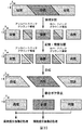
図28は、前景領域、背景領域、カバードバックグラウンド領域、およびアンカバードバックグラウンド領域に属する画素毎に分割された画像と、画素の画素値を時間方向に展開したモデル図との対応を示す図である。
【0197】
図28に示すように、領域特定部103は、入力画像の前景領域、背景領域、カバードバックグラウンド領域、およびアンカバードバックグラウンド領域を特定する。
【0198】
図29は、前景領域の画像、背景領域の画像、カバードバックグラウンド領域の前景成分画像、カバードバックグラウンド領域の背景の成分、アンカバードバックグラウンド領域の前景の成分、およびアンカバードバックグラウンド領域の背景の成分に分離された入力画像と、画素の画素値を時間方向に展開したモデル図との対応を示す図である。
【0199】
図29に示すように、入力画像は、領域特定部103により、前景領域、背景領域、カバードバックグラウンド領域、およびアンカバードバックグラウンド領域を特定される。入力画像は、前景背景分離部105により、特定された前景領域、背景領域、カバードバックグラウンド領域、およびアンカバードバックグラウンド領域、および混合比算出部104により検出された混合比αを基に、前景領域の画像、カバードバックグラウンド領域の前景の成分、およびアンカバードバックグラウンド領域の前景の成分からなる前景成分画像、並びに背景領域の画像、カバードバックグラウンド領域の背景の成分、およびアンカバードバックグラウンド領域の背景の成分からなる背景成分画像に分離される。
【0200】
分離された前景成分画像、および背景成分画像は、それぞれの画像毎に、処理される。
【0201】
前景背景分離部105は、入力画像を、領域情報および混合比αを基に、前景領域の画像、背景領域の画像、カバードバックグラウンド領域の前景成分画像、カバードバックグラウンド領域の背景成分画像、アンカバードバックグラウンド領域の前景成分画像、およびアンカバードバックグラウンド領域の背景成分画像に分離するようにしてもよい。
【0202】
図30は、前景領域、背景領域、および混合領域に分割された画像の例を示す図である。領域特定部103は、入力画像の、前景領域、背景領域、および混合領域を特定する。画像処理装置は、前景領域、背景領域、および混合領域を示す領域情報を基に、入力画像を、前景領域の画像、背景領域の画像、および混合領域の画像に分割することができる。
【0203】
図31に示すように、前景背景分離部105は、領域特定部103から供給された領域情報、および混合比算出部104から供給された混合比αを基に、混合領域の画像を、混合領域の前景成分画像および混合領域の背景成分画像に分離する。
【0204】
図32に示すように、分離された背景成分画像は、混合領域の画素値が補正され、分離された前景成分画像は、動きボケが除去される。
【0205】
図33に示すように、入力画像は、領域に分割され、前景の成分と背景の成分とに分離される。分離された入力画像は、前景成分画像および背景成分画像に合成される。
【0206】
前景成分画像に含まれる動きボケは、除去される。背景成分画像は、混合領域に対応する画素値が補正される。
【0207】
動きボケが除去された前景成分画像、および補正された背景成分画像は、個々に処理される。
【0208】
図34は、本発明に係る画像処理装置の画像の処理を説明するフローチャートである。
【0209】
ステップS101において、領域特定部103は、動き検出部102から供給された動きベクトルおよびその位置情報、並びに入力画像を基に、入力画像の前景領域、背景領域、カバードバックグラウンド領域、およびアンカバードバックグラウンド領域を特定する。領域特定の処理の詳細は、後述する。
【0210】
ステップS102において、混合比算出部104は、領域特定部103から供給された領域情報および入力画像を基に、混合比αを算出する。混合比算出部104の混合比αを算出する処理の詳細は、後述する。
【0211】
ステップS103において、前景背景分離部105は、領域特定部103から供給された領域情報、および混合比算出部104から供給された混合比αを基に、入力画像を、前景の成分からなる前景成分画像、および背景の成分からなる背景成分画像に分離する。前景背景分離部105の画像の分離の処理の詳細は、後述する。
【0212】
ステップS104において、動きボケ除去部106は、動き検出部102から供給された動きベクトルおよびその位置情報、並びに領域特定部103から供給された領域情報を基に、前景背景分離部105から供給された前景成分画像の動きボケを除去する。
【0213】
ステップS105において、補正部107は、前景背景分離部105から供給された背景成分画像の混合領域に対応する画素値を補正する。
【0214】
ステップS106において、動きボケ除去画像処理部108は、動きボケが除去された前景成分画像、および補正された背景成分画像毎に、画像の処理を実行して、処理は終了する。動きボケ除去画像処理部108が実行する画像処理の詳細は、後述する。
【0215】
このように、本発明に係る画像処理装置は、入力画像を、前景成分画像および背景成分画像に分離し、前景成分画像から動きボケを除去して、動きボケが除去された前景成分画像、および背景成分画像毎に画像処理を実行する。
【0216】
以下、領域特定部103、混合比算出部104、前景背景分離部105、動きボケ除去部106、および動きボケ除去画像処理部108のそれぞれの構成について説明する。
【0217】
図35は、領域特定部103の構成の一例を示すブロック図である。図35に構成を示す領域特定部103は、動きベクトルを利用しない。フレームメモリ201は、入力された画像をフレーム単位で記憶する。フレームメモリ201は、処理の対象がフレーム#nであるとき、フレーム#nの2つ前のフレームであるフレーム#n-2、フレーム#nの1つ前のフレームであるフレーム#n-1、フレーム#n、フレーム#nの1つ後のフレームであるフレーム#n+1、およびフレーム#nの2つ後のフレームであるフレーム#n+2を記憶する。
【0218】
静動判定部202−1は、フレーム#nの領域特定の対象である画素の画像上の位置と同一の位置にあるフレーム#n+2の画素の画素値、およびフレーム#nの領域特定の対象である画素の画像上の位置と同一の位置にあるフレーム#n+1の画素の画素値をフレームメモリ201から読み出して、読み出した画素値の差の絶対値を算出する。静動判定部202−1は、フレーム#n+2の画素値とフレーム#n+1の画素値との差の絶対値が、予め設定している閾値Thより大きいか否かを判定し、差の絶対値が閾値Thより大きいと判定された場合、動きを示す静動判定を領域判定部203−1に供給する。フレーム#n+2の画素の画素値とフレーム#n+1の画素の画素値との差の絶対値が閾値Th以下であると判定された場合、静動判定部202−1は、静止を示す静動判定を領域判定部203−1に供給する。
【0219】
静動判定部202−2は、フレーム#nの領域特定の対象である画素の画像上の位置と同一の位置にあるフレーム#n+1の画素の画素値、およびフレーム#nの対象となる画素の画素値をフレームメモリ201から読み出して、画素値の差の絶対値を算出する。静動判定部202−2は、フレーム#n+1の画素値とフレーム#nの画素値との差の絶対値が、予め設定している閾値Thより大きいか否かを判定し、画素値の差の絶対値が、閾値Thより大きいと判定された場合、動きを示す静動判定を領域判定部203−1および領域判定部203−2に供給する。フレーム#n+1の画素の画素値とフレーム#nの画素の画素値との差の絶対値が、閾値Th以下であると判定された場合、静動判定部202−2は、静止を示す静動判定を領域判定部203−1および領域判定部203−2に供給する。
【0220】
静動判定部202−3は、フレーム#nの領域特定の対象である画素の画素値、およびフレーム#nの領域特定の対象である画素の画像上の位置と同一の位置にあるフレーム#n-1の画素の画素値をフレームメモリ201から読み出して、画素値の差の絶対値を算出する。静動判定部202−3は、フレーム#nの画素値とフレーム#n-1の画素値との差の絶対値が、予め設定している閾値Thより大きいか否かを判定し、画素値の差の絶対値が、閾値Thより大きいと判定された場合、動きを示す静動判定を領域判定部203−2および領域判定部203−3に供給する。フレーム#nの画素の画素値とフレーム#n-1の画素の画素値との差の絶対値が、閾値Th以下であると判定された場合、静動判定部202−3は、静止を示す静動判定を領域判定部203−2および領域判定部203−3に供給する。
【0221】
静動判定部202−4は、フレーム#nの領域特定の対象である画素の画像上の位置と同一の位置にあるフレーム#n-1の画素の画素値、およびフレーム#nの領域特定の対象である画素の画像上の位置と同一の位置にあるフレーム#n-2の画素の画素値をフレームメモリ201から読み出して、画素値の差の絶対値を算出する。静動判定部202−4は、フレーム#n-1の画素値とフレーム#n-2の画素値との差の絶対値が、予め設定している閾値Thより大きいか否かを判定し、画素値の差の絶対値が、閾値Thより大きいと判定された場合、動きを示す静動判定を領域判定部203−3に供給する。フレーム#n-1の画素の画素値とフレーム#n-2の画素の画素値との差の絶対値が、閾値Th以下であると判定された場合、静動判定部202−4は、静止を示す静動判定を領域判定部203−3に供給する。
【0222】
領域判定部203−1は、静動判定部202−1から供給された静動判定が静止を示し、かつ、静動判定部202−2から供給された静動判定が動きを示しているとき、フレーム#nにおける領域特定の対象である画素がアンカバードバックグラウンド領域に属すると判定し、領域の判定される画素に対応するアンカバードバックグラウンド領域判定フラグに、アンカバードバックグラウンド領域に属することを示す”1”を設定する。
【0223】
領域判定部203−1は、静動判定部202−1から供給された静動判定が動きを示すか、または、静動判定部202−2から供給された静動判定が静止を示しているとき、フレーム#nにおける領域特定の対象である画素がアンカバードバックグラウンド領域に属しないと判定し、領域の判定される画素に対応するアンカバードバックグラウンド領域判定フラグに、アンカバードバックグラウンド領域に属しないことを示す”0”を設定する。
【0224】
領域判定部203−1は、このように”1”または”0”が設定されたアンカバードバックグラウンド領域判定フラグを判定フラグ格納フレームメモリ204に供給する。
【0225】
領域判定部203−2は、静動判定部202−2から供給された静動判定が静止を示し、かつ、静動判定部202−3から供給された静動判定が静止を示しているとき、フレーム#nにおける領域特定の対象である画素が静止領域に属すると判定し、領域の判定される画素に対応する静止領域判定フラグに、静止領域に属することを示す”1”を設定する。
【0226】
領域判定部203−2は、静動判定部202−2から供給された静動判定が動きを示すか、または、静動判定部202−3から供給された静動判定が動きを示しているとき、フレーム#nにおける領域特定の対象である画素が静止領域に属しないと判定し、領域の判定される画素に対応する静止領域判定フラグに、静止領域に属しないことを示す”0”を設定する。
【0227】
領域判定部203−2は、このように”1”または”0”が設定された静止領域判定フラグを判定フラグ格納フレームメモリ204に供給する。
【0228】
領域判定部203−2は、静動判定部202−2から供給された静動判定が動きを示し、かつ、静動判定部202−3から供給された静動判定が動きを示しているとき、フレーム#nにおける領域特定の対象である画素が動き領域に属すると判定し、領域の判定される画素に対応する動き領域判定フラグに、動き領域に属することを示す”1”を設定する。
【0229】
領域判定部203−2は、静動判定部202−2から供給された静動判定が静止を示すか、または、静動判定部202−3から供給された静動判定が静止を示しているとき、フレーム#nにおける領域特定の対象である画素が動き領域に属しないと判定し、領域の判定される画素に対応する動き領域判定フラグに、動き領域に属しないことを示す”0”を設定する。
【0230】
領域判定部203−2は、このように”1”または”0”が設定された動き領域判定フラグを判定フラグ格納フレームメモリ204に供給する。
【0231】
領域判定部203−3は、静動判定部202−3から供給された静動判定が動きを示し、かつ、静動判定部202−4から供給された静動判定が静止を示しているとき、フレーム#nにおける領域特定の対象である画素がカバードバックグラウンド領域に属すると判定し、領域の判定される画素に対応するカバードバックグラウンド領域判定フラグに、カバードバックグラウンド領域に属することを示す”1”を設定する。
【0232】
領域判定部203−3は、静動判定部202−3から供給された静動判定が静止を示すか、または、静動判定部202−4から供給された静動判定が動きを示しているとき、フレーム#nにおける領域特定の対象である画素がカバードバックグラウンド領域に属しないと判定し、領域の判定される画素に対応するカバードバックグラウンド領域判定フラグに、カバードバックグラウンド領域に属しないことを示す”0”を設定する。
【0233】
領域判定部203−3は、このように”1”または”0”が設定されたカバードバックグラウンド領域判定フラグを判定フラグ格納フレームメモリ204に供給する。
【0234】
判定フラグ格納フレームメモリ204は、領域判定部203−1から供給されたアンカバードバックグラウンド領域判定フラグ、領域判定部203−2から供給された静止領域判定フラグ、領域判定部203−2から供給された動き領域判定フラグ、および領域判定部203−3から供給されたカバードバックグラウンド領域判定フラグをそれぞれ記憶する。
【0235】
判定フラグ格納フレームメモリ204は、記憶しているアンカバードバックグラウンド領域判定フラグ、静止領域判定フラグ、動き領域判定フラグ、およびカバードバックグラウンド領域判定フラグを合成部205に供給する。合成部205は、判定フラグ格納フレームメモリ204から供給された、アンカバードバックグラウンド領域判定フラグ、静止領域判定フラグ、動き領域判定フラグ、およびカバードバックグラウンド領域判定フラグを基に、各画素が、アンカバードバックグラウンド領域、静止領域、動き領域、およびカバードバックグラウンド領域のいずれかに属することを示す領域情報を生成し、判定フラグ格納フレームメモリ206に供給する。
【0236】
判定フラグ格納フレームメモリ206は、合成部205から供給された領域情報を記憶すると共に、記憶している領域情報を出力する。
【0237】
次に、領域特定部103の処理の例を図36乃至図40を参照して説明する。
【0238】
前景に対応するオブジェクトが移動しているとき、オブジェクトに対応する画像の画面上の位置は、フレーム毎に変化する。図36に示すように、フレーム#nにおいて、Yn(x,y)で示される位置に位置するオブジェクトに対応する画像は、次のフレームであるフレーム#n+1において、Yn+1(x,y)に位置する。
【0239】
前景のオブジェクトに対応する画像の動き方向に隣接して1列に並ぶ画素の画素値を時間方向に展開したモデル図を図37に示す。例えば、前景のオブジェクトに対応する画像の動き方向が画面に対して水平であるとき、図37におけるモデル図は、1つのライン上の隣接する画素の画素値を時間方向に展開したモデルを示す。
【0240】
図37において、フレーム#nにおけるラインは、フレーム#n+1におけるラインと同一である。
【0241】
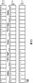
フレーム#nにおいて、左から2番目の画素乃至13番目の画素に含まれているオブジェクトに対応する前景の成分は、フレーム#n+1において、左から6番目乃至17番目の画素に含まれる。
【0242】
フレーム#nにおいて、カバードバックグラウンド領域に属する画素は、左から11番目乃至13番目の画素であり、アンカバードバックグラウンド領域に属する画素は、左から2番目乃至4番目の画素である。フレーム#n+1において、カバードバックグラウンド領域に属する画素は、左から15番目乃至17番目の画素であり、アンカバードバックグラウンド領域に属する画素は、左から6番目乃至8番目の画素である。
【0243】
図37に示す例において、フレーム#nに含まれる前景の成分が、フレーム#n+1において4画素移動しているので、動き量vは、4である。仮想分割数は、動き量vに対応し、4である。
【0244】
次に、注目しているフレームの前後における混合領域に属する画素の画素値の変化について説明する。
【0245】
図38に示す、背景が静止し、前景の動き量vが4であるフレーム#nにおいて、カバードバックグラウンド領域に属する画素は、左から15番目乃至17番目の画素である。動き量vが4であるので、1つ前のフレーム#n-1において、左から15番目乃至17番目の画素は、背景の成分のみを含み、背景領域に属する。また、更に1つ前のフレーム#n-2において、左から15番目乃至17番目の画素は、背景の成分のみを含み、背景領域に属する。
【0246】
ここで、背景に対応するオブジェクトが静止しているので、フレーム#n-1の左から15番目の画素の画素値は、フレーム#n-2の左から15番目の画素の画素値から変化しない。同様に、フレーム#n-1の左から16番目の画素の画素値は、フレーム#n-2の左から16番目の画素の画素値から変化せず、フレーム#n-1の左から17番目の画素の画素値は、フレーム#n-2の左から17番目の画素の画素値から変化しない。
【0247】
すなわち、フレーム#nにおけるカバードバックグラウンド領域に属する画素に対応する、フレーム#n-1およびフレーム#n-2の画素は、背景の成分のみから成り、画素値が変化しないので、その差の絶対値は、ほぼ0の値となる。従って、フレーム#nにおける混合領域に属する画素に対応する、フレーム#n-1およびフレーム#n-2の画素に対する静動判定は、静動判定部202−4により、静止と判定される。
【0248】
フレーム#nにおけるカバードバックグラウンド領域に属する画素は、前景の成分を含むので、フレーム#n-1における背景の成分のみから成る場合と、画素値が異なる。従って、フレーム#nにおける混合領域に属する画素、および対応するフレーム#n-1の画素に対する静動判定は、静動判定部202−3により、動きと判定される。
【0249】
このように、領域判定部203−3は、静動判定部202−3から動きを示す静動判定の結果が供給され、静動判定部202−4から静止を示す静動判定の結果が供給されたとき、対応する画素がカバードバックグラウンド領域に属すると判定する。
【0250】
図39に示す、背景が静止し、前景の動き量vが4であるフレーム#nにおいて、アンカバードバックグラウンド領域に含まれる画素は、左から2番目乃至4番目の画素である。動き量vが4であるので、1つ後のフレーム#n+1において、左から2番目乃至4番目の画素は、背景の成分のみを含み、背景領域に属する。また、更に1つ後のフレーム#n+2において、左から2番目乃至4番目の画素は、背景の成分のみを含み、背景領域に属する。
【0251】
ここで、背景に対応するオブジェクトが静止しているので、フレーム#n+2の左から2番目の画素の画素値は、フレーム#n+1の左から2番目の画素の画素値から変化しない。同様に、フレーム#n+2の左から3番目の画素の画素値は、フレーム#n+1の左から3番目の画素の画素値から変化せず、フレーム#n+2の左から4番目の画素の画素値は、フレーム#n+1の左から4番目の画素の画素値から変化しない。
【0252】
すなわち、フレーム#nにおけるアンカバードバックグラウンド領域に属する画素に対応する、フレーム#n+1およびフレーム#n+2の画素は、背景の成分のみから成り、画素値が変化しないので、その差の絶対値は、ほぼ0の値となる。従って、フレーム#nにおける混合領域に属する画素に対応する、フレーム#n+1およびフレーム#n+2の画素に対する静動判定は、静動判定部202−1により、静止と判定される。
【0253】
フレーム#nにおけるアンカバードバックグラウンド領域に属する画素は、前景の成分を含むので、フレーム#n+1における背景の成分のみから成る場合と、画素値が異なる。従って、フレーム#nにおける混合領域に属する画素、および対応するフレーム#n+1の画素に対する静動判定は、静動判定部202−2により、動きと判定される。
【0254】
このように、領域判定部203−1は、静動判定部202−2から動きを示す静動判定の結果が供給され、静動判定部202−1から静止を示す静動判定の結果が供給されたとき、対応する画素がアンカバードバックグラウンド領域に属すると判定する。
【0255】
図40は、フレーム#nにおける領域特定部103の判定条件を示す図である。フレーム#nの判定の対象となる画素の画像上の位置と同一の位置にあるフレーム#n-2の画素と、フレーム#nの判定の対象となる画素の画像上の位置と同一の位置にあるフレーム#n-1の画素とが静止と判定され、フレーム#nの判定の対象となる画素の画像上の位置と同一の位置にあるフレーム#n-1の画素と、フレーム#nの画素とが動きと判定されたとき、領域特定部103は、フレーム#nの判定の対象となる画素がカバードバックグラウンド領域に属すると判定する。
【0256】
フレーム#nの判定の対象となる画素の画像上の位置と同一の位置にあるフレーム#n-1の画素と、フレーム#nの画素とが静止と判定され、フレーム#nの画素と、フレーム#nの判定の対象となる画素の画像上の位置と同一の位置にあるフレーム#n+1の画素とが静止と判定されたとき、領域特定部103は、フレーム#nの判定の対象となる画素が静止領域に属すると判定する。
【0257】
フレーム#nの判定の対象となる画素の画像上の位置と同一の位置にあるフレーム#n-1の画素と、フレーム#nの画素とが動きと判定され、フレーム#nの画素と、フレーム#nの判定の対象となる画素の画像上の位置と同一の位置にあるフレーム#n+1の画素とが動きと判定されたとき、領域特定部103は、フレーム#nの判定の対象となる画素が動き領域に属すると判定する。
【0258】
フレーム#nの画素と、フレーム#nの判定の対象となる画素の画像上の位置と同一の位置にあるフレーム#n+1の画素とが動きと判定され、フレーム#nの判定の対象となる画素の画像上の位置と同一の位置にあるフレーム#n+1の画素と、フレーム#nの判定の対象となる画素の画像上の位置と同一の位置にあるフレーム#n+2の画素とが静止と判定されたとき、領域特定部103は、フレーム#nの判定の対象となる画素がアンカバードバックグラウンド領域に属すると判定する。
【0259】
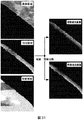
図41は、領域特定部103の領域の特定の結果の例を示す図である。図41(A)において、カバードバックグラウンド領域に属すると判定された画素は、白で表示されている。図41(B)において、アンカバードバックグラウンド領域に属すると判定された画素は、白で表示されている。
【0260】
図41(C)において、動き領域に属すると判定された画素は、白で表示されている。図41(D)において、静止領域に属すると判定された画素は、白で表示されている。
【0261】
図42は、判定フラグ格納フレームメモリ206が出力する領域情報の内、混合領域を示す領域情報を画像として示す図である。図42において、カバードバックグラウンド領域またはアンカバードバックグラウンド領域に属すると判定された画素、すなわち混合領域に属すると判定された画素は、白で表示されている。判定フラグ格納フレームメモリ206が出力する混合領域を示す領域情報は、混合領域、および前景領域内のテクスチャの無い部分に囲まれたテクスチャの有る部分を示す。
【0262】
次に、図43のフローチャートを参照して、領域特定部103の領域特定の処理を説明する。ステップS201において、フレームメモリ201は、判定の対象となるフレーム#nを含むフレーム#n-2乃至フレーム#n+2の画像を取得する。
【0263】
ステップS202において、静動判定部202−3は、フレーム#n-1の画素とフレーム#nの同一位置の画素とで、静止か否かを判定し、静止と判定された場合、ステップS203に進み、静動判定部202−2は、フレーム#nの画素とフレーム#n+1の同一位置の画素とで、静止か否かを判定する。
【0264】
ステップS203において、フレーム#nの画素とフレーム#n+1の同一位置の画素とで、静止と判定された場合、ステップS204に進み、領域判定部203−2は、領域の判定される画素に対応する静止領域判定フラグに、静止領域に属することを示す”1”を設定する。領域判定部203−2は、静止領域判定フラグを判定フラグ格納フレームメモリ204に供給し、手続きは、ステップS205に進む。
【0265】
ステップS202において、フレーム#n-1の画素とフレーム#nの同一位置の画素とで、動きと判定された場合、または、ステップS203において、フレーム#nの画素とフレーム#n+1の同一位置の画素とで、動きと判定された場合、フレーム#nの画素が静止領域には属さないので、ステップS204の処理はスキップされ、手続きは、ステップS205に進む。
【0266】
ステップS205において、静動判定部202−3は、フレーム#n-1の画素とフレーム#nの同一位置の画素とで、動きか否かを判定し、動きと判定された場合、ステップS206に進み、静動判定部202−2は、フレーム#nの画素とフレーム#n+1の同一位置の画素とで、動きか否かを判定する。
【0267】
ステップS206において、フレーム#nの画素とフレーム#n+1の同一位置の画素とで、動きと判定された場合、ステップS207に進み、領域判定部203−2は、領域の判定される画素に対応する動き領域判定フラグに、動き領域に属することを示す”1”を設定する。領域判定部203−2は、動き領域判定フラグを判定フラグ格納フレームメモリ204に供給し、手続きは、ステップS208に進む。
【0268】
ステップS205において、フレーム#n-1の画素とフレーム#nの同一位置の画素とで、静止と判定された場合、または、ステップS206において、フレーム#nの画素とフレーム#n+1の同一位置の画素とで、静止と判定された場合、フレーム#nの画素が動き領域には属さないので、ステップS207の処理はスキップされ、手続きは、ステップS208に進む。
【0269】
ステップS208において、静動判定部202−4は、フレーム#n-2の画素とフレーム#n-1の同一位置の画素とで、静止か否かを判定し、静止と判定された場合、ステップS209に進み、静動判定部202−3は、フレーム#n-1の画素とフレーム#nの同一位置の画素とで、動きか否かを判定する。
【0270】
ステップS209において、フレーム#n-1の画素とフレーム#nの同一位置の画素とで、動きと判定された場合、ステップS210に進み、領域判定部203−3は、領域の判定される画素に対応するカバードバックグラウンド領域判定フラグに、カバードバックグラウンド領域に属することを示す”1”を設定する。領域判定部203−3は、カバードバックグラウンド領域判定フラグを判定フラグ格納フレームメモリ204に供給し、手続きは、ステップS211に進む。
【0271】
ステップS208において、フレーム#n-2の画素とフレーム#n-1の同一位置の画素とで、動きと判定された場合、または、ステップS209において、フレーム#n-1の画素とフレーム#nの同一位置の画素とで、静止と判定された場合、フレーム#nの画素がカバードバックグラウンド領域には属さないので、ステップS210の処理はスキップされ、手続きは、ステップS211に進む。
【0272】
ステップS211において、静動判定部202−2は、フレーム#nの画素とフレーム#n+1の同一位置の画素とで、動きか否かを判定し、動きと判定された場合、ステップS212に進み、静動判定部202−1は、フレーム#n+1の画素とフレーム#n+2の同一位置の画素とで、静止か否かを判定する。
【0273】
ステップS212において、フレーム#n+1の画素とフレーム#n+2の同一位置の画素とで、静止と判定された場合、ステップS213に進み、領域判定部203−1は、領域の判定される画素に対応するアンカバードバックグラウンド領域判定フラグに、アンカバードバックグラウンド領域に属することを示す”1”を設定する。領域判定部203−1は、アンカバードバックグラウンド領域判定フラグを判定フラグ格納フレームメモリ204に供給し、手続きは、ステップS214に進む。
【0274】
ステップS211において、フレーム#nの画素とフレーム#n+1の同一位置の画素とで、静止と判定された場合、または、ステップS212において、フレーム#n+1の画素とフレーム#n+2の同一位置の画素とで、動きと判定された場合、フレーム#nの画素がアンカバードバックグラウンド領域には属さないので、ステップS213の処理はスキップされ、手続きは、ステップS214に進む。
【0275】
ステップS214において、領域特定部103は、フレーム#nの全ての画素について領域を特定したか否かを判定し、フレーム#nの全ての画素について領域を特定していないと判定された場合、手続きは、ステップS202に戻り、他の画素について、領域特定の処理を繰り返す。
【0276】
ステップS214において、フレーム#nの全ての画素について領域を特定したと判定された場合、ステップS215に進み、合成部205は、判定フラグ格納フレームメモリ204に記憶されているアンカバードバックグラウンド領域判定フラグ、およびカバードバックグラウンド領域判定フラグを基に、混合領域を示す領域情報を生成し、更に、各画素が、アンカバードバックグラウンド領域、静止領域、動き領域、およびカバードバックグラウンド領域のいずれかに属することを示す領域情報を生成し、生成した領域情報を判定フラグ格納フレームメモリ206に設定し、処理は終了する。
【0277】
このように、領域特定部103は、フレームに含まれている画素のそれぞれについて、動き領域、静止領域、アンカバードバックグラウンド領域、またはカバードバックグラウンド領域に属することを示す領域情報を生成することができる。
【0278】
なお、領域特定部103は、アンカバードバックグラウンド領域およびカバードバックグラウンド領域に対応する領域情報に論理和を適用することにより、混合領域に対応する領域情報を生成して、フレームに含まれている画素のそれぞれについて、動き領域、静止領域、または混合領域に属することを示すフラグから成る領域情報を生成するようにしてもよい。
【0279】
前景に対応するオブジェクトがテクスチャを有す場合、領域特定部103は、より正確に動き領域を特定することができる。
【0280】
領域特定部103は、動き領域を示す領域情報を前景領域を示す領域情報として、また、静止領域を示す領域情報を背景領域を示す領域情報として出力することができる。
【0281】
なお、背景に対応するオブジェクトが静止しているとして説明したが、背景領域に対応する画像が動きを含んでいても上述した領域を特定する処理を適用することができる。例えば、背景領域に対応する画像が一様に動いているとき、領域特定部103は、この動きに対応して画像全体をシフトさせ、背景に対応するオブジェクトが静止している場合と同様に処理する。また、背景領域に対応する画像が局所毎に異なる動きを含んでいるとき、領域特定部103は、動きに対応した画素を選択して、上述の処理を実行する。
【0282】
図44は、領域特定部103の構成の他の例を示すブロック図である。図44に示す領域特定部103は、動きベクトルを使用しない。背景画像生成部301は、入力画像に対応する背景画像を生成し、生成した背景画像を2値オブジェクト画像抽出部302に供給する。背景画像生成部301は、例えば、入力画像に含まれる背景のオブジェクトに対応する画像オブジェクトを抽出して、背景画像を生成する。
【0283】
前景のオブジェクトに対応する画像の動き方向に隣接して1列に並ぶ画素の画素値を時間方向に展開したモデル図の例を図45に示す。例えば、前景のオブジェクトに対応する画像の動き方向が画面に対して水平であるとき、図45におけるモデル図は、1つのライン上の隣接する画素の画素値を時間方向に展開したモデルを示す。
【0284】
図45において、フレーム#nにおけるラインは、フレーム#n-1およびフレーム#n+1におけるラインと同一である。
【0285】
フレーム#nにおいて、左から6番目の画素乃至17番目の画素に含まれているオブジェクトに対応する前景の成分は、フレーム#n-1において、左から2番目乃至13番目の画素に含まれ、フレーム#n+1において、左から10番目乃至21番目の画素に含まれる。
【0286】
フレーム#n-1において、カバードバックグラウンド領域に属する画素は、左から11番目乃至13番目の画素であり、アンカバードバックグラウンド領域に属する画素は、左から2番目乃至4番目の画素である。フレーム#nにおいて、カバードバックグラウンド領域に属する画素は、左から15番目乃至17番目の画素であり、アンカバードバックグラウンド領域に属する画素は、左から6番目乃至8番目の画素である。フレーム#n+1において、カバードバックグラウンド領域に属する画素は、左から19番目乃至21番目の画素であり、アンカバードバックグラウンド領域に属する画素は、左から10番目乃至12番目の画素である。
【0287】
フレーム#n-1において、背景領域に属する画素は、左から1番目の画素、および左から14番目乃至21番目の画素である。フレーム#nにおいて、背景領域に属する画素は、左から1番目乃至5番目の画素、および左から18番目乃至21番目の画素である。フレーム#n+1において、背景領域に属する画素は、左から1番目乃至9番目の画素である。
【0288】
背景画像生成部301が生成する、図45の例に対応する背景画像の例を図46に示す。背景画像は、背景のオブジェクトに対応する画素から構成され、前景のオブジェクトに対応する画像の成分を含まない。
【0289】
2値オブジェクト画像抽出部302は、背景画像および入力画像の相関を基に、2値オブジェクト画像を生成し、生成した2値オブジェクト画像を時間変化検出部303に供給する。
【0290】
図47は、2値オブジェクト画像抽出部302の構成を示すブロック図である。相関値演算部321は、背景画像生成部301から供給された背景画像および入力画像の相関を演算し、相関値を生成して、生成した相関値をしきい値処理部322に供給する。
【0291】
相関値演算部321は、例えば、図48(A)に示すように、X4を中心とした3×3の背景画像の中のブロックと、図48(B)に示すように、背景画像の中のブロックに対応するY4を中心とした3×3の入力画像の中のブロックに、式(4)を適用して、Y4に対応する相関値を算出する。
【0292】
【数2】
相関値演算部321は、このように各画素に対応して算出された相関値をしきい値処理部322に供給する。
【0294】
また、相関値演算部321は、例えば、図49(A)に示すように、X4を中心とした3×3の背景画像の中のブロックと、図49(B)に示すように、背景画像の中のブロックに対応するY4を中心とした3×3の入力画像の中のブロックに、式(7)を適用して、Y4に対応する差分絶対値を算出するようにしてもよい。
【0295】
【数5】
相関値演算部321は、このように算出された差分絶対値を相関値として、しきい値処理部322に供給する。
【0297】
しきい値処理部322は、相関画像の画素値としきい値th0とを比較して、相関値がしきい値th0以下である場合、2値オブジェクト画像の画素値に1を設定し、相関値がしきい値th0より大きい場合、2値オブジェクト画像の画素値に0を設定して、0または1が画素値に設定された2値オブジェクト画像を出力する。しきい値処理部322は、しきい値th0を予め記憶するようにしてもよく、または、外部から入力されたしきい値th0を使用するようにしてもよい。
【0298】
図50は、図45に示す入力画像のモデルに対応する2値オブジェクト画像の例を示す図である。2値オブジェクト画像において、背景画像と相関の高い画素には、画素値に0が設定される。
【0299】
図51は、時間変化検出部303の構成を示すブロック図である。フレームメモリ341は、フレーム#nの画素について領域を判定するとき、2値オブジェクト画像抽出部302から供給された、フレーム#n-1、フレーム#n、およびフレーム#n+1の2値オブジェクト画像を記憶する。
【0300】
領域判定部342は、フレームメモリ341に記憶されているフレーム#n-1、フレーム#n、およびフレーム#n+1の2値オブジェクト画像を基に、フレーム#nの各画素について領域を判定して、領域情報を生成し、生成した領域情報を出力する。
【0301】
図52は、領域判定部342の判定を説明する図である。フレーム#nの2値オブジェクト画像の注目している画素が0であるとき、領域判定部342は、フレーム#nの注目している画素が背景領域に属すると判定する。
【0302】
フレーム#nの2値オブジェクト画像の注目している画素が1であり、フレーム#n-1の2値オブジェクト画像の対応する画素が1であり、フレーム#n+1の2値オブジェクト画像の対応する画素が1であるとき、領域判定部342は、フレーム#nの注目している画素が前景領域に属すると判定する。
【0303】
フレーム#nの2値オブジェクト画像の注目している画素が1であり、フレーム#n-1の2値オブジェクト画像の対応する画素が0であるとき、領域判定部342は、フレーム#nの注目している画素がカバードバックグラウンド領域に属すると判定する。
【0304】
フレーム#nの2値オブジェクト画像の注目している画素が1であり、フレーム#n+1の2値オブジェクト画像の対応する画素が0であるとき、領域判定部342は、フレーム#nの注目している画素がアンカバードバックグラウンド領域に属すると判定する。
【0305】
図53は、図45に示す入力画像のモデルに対応する2値オブジェクト画像について、時間変化検出部303の判定した例を示す図である。時間変化検出部303は、2値オブジェクト画像のフレーム#nの対応する画素が0なので、フレーム#nの左から1番目乃至5番目の画素を背景領域に属すると判定する。
【0306】
時間変化検出部303は、2値オブジェクト画像のフレーム#nの画素が1であり、フレーム#n+1の対応する画素が0なので、左から6番目乃至9番目の画素をアンカバードバックグラウンド領域に属すると判定する。
【0307】
時間変化検出部303は、2値オブジェクト画像のフレーム#nの画素が1であり、フレーム#n-1の対応する画素が1であり、フレーム#n+1の対応する画素が1なので、左から10番目乃至13番目の画素を前景領域に属すると判定する。
【0308】
時間変化検出部303は、2値オブジェクト画像のフレーム#nの画素が1であり、フレーム#n-1の対応する画素が0なので、左から14番目乃至17番目の画素をカバードバックグラウンド領域に属すると判定する。
【0309】
時間変化検出部303は、2値オブジェクト画像のフレーム#nの対応する画素が0なので、左から18番目乃至21番目の画素を背景領域に属すると判定する。
【0310】
次に、図54のフローチャートを参照して、領域判定部103の領域特定の処理を説明する。ステップS301において、領域判定部103の背景画像生成部301は、入力画像を基に、例えば、入力画像に含まれる背景のオブジェクトに対応する画像オブジェクトを抽出して背景画像を生成し、生成した背景画像を2値オブジェクト画像抽出部302に供給する。
【0311】
ステップS302において、2値オブジェクト画像抽出部302は、例えば、図48を参照して説明した演算により、入力画像と背景画像生成部301から供給された背景画像との相関値を演算する。ステップS303において、2値オブジェクト画像抽出部302は、例えば、相関値としきい値th0とを比較することにより、相関値およびしきい値th0から2値オブジェクト画像を演算する。
【0312】
ステップS304において、時間変化検出部303は、領域判定の処理を実行して、処理は終了する。
【0313】
図55のフローチャートを参照して、ステップS304に対応する領域判定の処理の詳細を説明する。ステップS321において、時間変化検出部303の領域判定部342は、フレームメモリ341に記憶されているフレーム#nにおいて、注目する画素が0であるか否かを判定し、フレーム#nにおいて、注目する画素が0であると判定された場合、ステップS322に進み、フレーム#nの注目する画素が背景領域に属すると設定して、処理は終了する。
【0314】
ステップS321において、フレーム#nにおいて、注目する画素が1であると判定された場合、ステップS323に進み、時間変化検出部303の領域判定部342は、フレームメモリ341に記憶されているフレーム#nにおいて、注目する画素が1であり、かつ、フレーム#n-1において、対応する画素が0であるか否かを判定し、フレーム#nにおいて、注目する画素が1であり、かつ、フレーム#n-1において、対応する画素が0であると判定された場合、ステップS324に進み、フレーム#nの注目する画素がカバードバックグラウンド領域に属すると設定して、処理は終了する。
【0315】
ステップS323において、フレーム#nにおいて、注目する画素が0であるか、または、フレーム#n-1において、対応する画素が1であると判定された場合、ステップS325に進み、時間変化検出部303の領域判定部342は、フレームメモリ341に記憶されているフレーム#nにおいて、注目する画素が1であり、かつ、フレーム#n+1において、対応する画素が0であるか否かを判定し、フレーム#nにおいて、注目する画素が1であり、かつ、フレーム#n+1において、対応する画素が0であると判定された場合、ステップS326に進み、フレーム#nの注目する画素がアンカバードバックグラウンド領域に属すると設定して、処理は終了する。
【0316】
ステップS325において、フレーム#nにおいて、注目する画素が0であるか、または、フレーム#n+1において、対応する画素が1であると判定された場合、ステップS327に進み、時間変化検出部303の領域判定部342は、フレーム#nの注目する画素を前景領域と設定して、処理は終了する。
【0317】
このように、領域特定部103は、入力された画像と対応する背景画像との相関値を基に、入力画像の画素が前景領域、背景領域、カバードバックグラウンド領域、およびアンカバードバックグラウンド領域のいずれかに属するかを特定して、特定した結果に対応する領域情報を生成することができる。
【0318】
図56は、領域特定部103の他の構成を示すブロック図である。図56に示す領域特定部103は、動き検出部102から供給される動きベクトルとその位置情報を使用する。図44に示す場合と同様の部分には、同一の番号を付してあり、その説明は省略する。
【0319】
ロバスト化部361は、2値オブジェクト画像抽出部302から供給された、N個のフレームの2値オブジェクト画像を基に、ロバスト化された2値オブジェクト画像を生成して、時間変化検出部303に出力する。
【0320】
図57は、ロバスト化部361の構成を説明するブロック図である。動き補償部381は、動き検出部102から供給された動きベクトルとその位置情報を基に、N個のフレームの2値オブジェクト画像の動きを補償して、動きが補償された2値オブジェクト画像をスイッチ382に出力する。
【0321】
図58および図59の例を参照して、動き補償部381の動き補償について説明する。例えば、フレーム#nの領域を判定するとき、図58に例を示すフレーム#n-1、フレーム#n、およびフレーム#n+1の2値オブジェクト画像が入力された場合、動き補償部381は、動き検出部102から供給された動きベクトルを基に、図59に例を示すように、フレーム#n-1の2値オブジェクト画像、およびフレーム#n+1の2値オブジェクト画像を動き補償して、動き補償された2値オブジェクト画像をスイッチ382に供給する。
【0322】
スイッチ382は、1番目のフレームの動き補償された2値オブジェクト画像をフレームメモリ383−1に出力し、2番目のフレームの動き補償された2値オブジェクト画像をフレームメモリ383−2に出力する。同様に、スイッチ382は、3番目乃至N−1番目のフレームの動き補償された2値オブジェクト画像のそれぞれをフレームメモリ383−3乃至フレームメモリ383−(N−1)のいずれかに出力し、N番目のフレームの動き補償された2値オブジェクト画像をフレームメモリ383−Nに出力する。
【0323】
フレームメモリ383−1は、1番目のフレームの動き補償された2値オブジェクト画像を記憶し、記憶されている2値オブジェクト画像を重み付け部384−1に出力する。フレームメモリ383−2は、2番目のフレームの動き補償された2値オブジェクト画像を記憶し、記憶されている2値オブジェクト画像を重み付け部384−2に出力する。
【0324】
同様に、フレームメモリ383−3乃至フレームメモリ383−(N−1)のそれぞれは、3番目のフレーム乃至N−1番目のフレームの動き補償された2値オブジェクト画像のいずれかを記憶し、記憶されている2値オブジェクト画像を重み付け部384−3乃至重み付け部384−(N−1)のいずれかに出力する。フレームメモリ383−Nは、N番目のフレームの動き補償された2値オブジェクト画像を記憶し、記憶されている2値オブジェクト画像を重み付け部384−Nに出力する。
【0325】
重み付け部384−1は、フレームメモリ383−1から供給された1番目のフレームの動き補償された2値オブジェクト画像の画素値に予め定めた重みw1を乗じて、積算部385に供給する。重み付け部384−2は、フレームメモリ383−2から供給された2番目のフレームの動き補償された2値オブジェクト画像の画素値に予め定めた重みw2を乗じて、積算部385に供給する。
【0326】
同様に、重み付け部384−3乃至重み付け部384−(N−1)のそれぞれは、フレームメモリ383−3乃至フレームメモリ383−(N−1)のいずれかから供給された3番目乃至N−1番目のいずれかのフレームの動き補償された2値オブジェクト画像の画素値に予め定めた重みw3乃至重みw(N-1)のいずれかを乗じて、積算部385に供給する。重み付け部384−Nは、フレームメモリ383−Nから供給されたN番目のフレームの動き補償された2値オブジェクト画像の画素値に予め定めた重みwNを乗じて、積算部385に供給する。
【0327】
積算部385は、1乃至N番目のフレームの動き補償され、それぞれ重みw1乃至wNのいずれかが乗じられた、2値オブジェクト画像の対応する画素値を積算して、積算された画素値を予め定めたしきい値th0と比較することにより2値オブジェクト画像を生成する。
【0328】
このように、ロバスト化部361は、N個の2値オブジェクト画像からロバスト化された2値オブジェト画像を生成して、時間変化検出部303に供給するので、図56に構成を示す領域特定部103は、入力画像にノイズが含まれていても、図44に示す場合に比較して、より正確に領域を特定することができる。
【0329】
次に、図56に構成を示す領域特定部103の領域特定の処理について、図60のフローチャートを参照して説明する。ステップS341乃至ステップS343の処理は、図54のフローチャートで説明したステップS301乃至ステップS303とそれぞれ同様なのでその説明は省略する。
【0330】
ステップS344において、ロバスト化部361は、ロバスト化の処理を実行する。
【0331】
ステップS345において、時間変化検出部303は、領域判定の処理を実行して、処理は終了する。ステップS345の処理の詳細は、図55のフローチャートを参照して説明した処理と同様なのでその説明は省略する。
【0332】
次に、図61のフローチャートを参照して、図60のステップS344の処理に対応する、ロバスト化の処理の詳細について説明する。ステップS361において、動き補償部381は、動き検出部102から供給される動きベクトルとその位置情報を基に、入力された2値オブジェクト画像の動き補償の処理を実行する。ステップS362において、フレームメモリ383−1乃至383−Nのいずれかは、スイッチ382を介して供給された動き補償された2値オブジェクト画像を記憶する。
【0333】
ステップS363において、ロバスト化部361は、N個の2値オブジェクト画像が記憶されたか否かを判定し、N個の2値オブジェクト画像が記憶されていないと判定された場合、ステップS361に戻り、2値オブジェクト画像の動き補償の処理および2値オブジェクト画像の記憶の処理を繰り返す。
【0334】
ステップS363において、N個の2値オブジェクト画像が記憶されたと判定された場合、ステップS364に進み、重み付け部384−1乃至384−Nのそれぞれは、N個の2値オブジェクト画像のそれぞれにw1乃至wNのいずれかの重みを乗じて、重み付けする。
【0335】
ステップS365において、積算部385は、重み付けされたN個の2値オブジェクト画像を積算する。
【0336】
ステップS366において、積算部385は、例えば、予め定められたしきい値th1との比較などにより、積算された画像から2値オブジェクト画像を生成して、処理は終了する。
【0337】
このように、図56に構成を示す領域特定部103は、ロバスト化された2値オブジェクト画像を基に、領域情報を生成することができる。
【0338】
以上のように、領域特定部103は、フレームに含まれている画素のそれぞれについて、動き領域、静止領域、アンカバードバックグラウンド領域、またはカバードバックグラウンド領域に属することを示す領域情報を生成することができる。
【0339】
図62は、混合比算出部104の構成の一例を示すブロック図である。推定混合比処理部401は、入力画像を基に、カバードバックグラウンド領域のモデルに対応する演算により、画素毎に推定混合比を算出して、算出した推定混合比を混合比決定部403に供給する。
【0340】
推定混合比処理部402は、入力画像を基に、アンカバードバックグラウンド領域のモデルに対応する演算により、画素毎に推定混合比を算出して、算出した推定混合比を混合比決定部403に供給する。
【0341】
前景に対応するオブジェクトがシャッタ時間内に等速で動いていると仮定できるので、混合領域に属する画素の混合比αは、以下の性質を有する。すなわち、混合比αは、画素の位置の変化に対応して、直線的に変化する。画素の位置の変化を1次元とすれば、混合比αの変化は、直線で表現することができ、画素の位置の変化を2次元とすれば、混合比αの変化は、平面で表現することができる。
【0342】
なお、1フレームの期間は短いので、前景に対応するオブジェクトが剛体であり、等速で移動していると仮定が成り立つ。
【0343】
この場合、混合比αの傾きは、前景のシャッタ時間内での動き量vの逆比となる。
【0344】
理想的な混合比αの例を図63に示す。理想的な混合比αの混合領域における傾きlは、動き量vの逆数として表すことができる。
【0345】
図63に示すように、理想的な混合比αは、背景領域において、1の値を有し、前景領域において、0の値を有し、混合領域において、0を越え1未満の値を有する。
【0346】
図64の例において、フレーム#nの左から7番目の画素の画素値C06は、フレーム#n-1の左から7番目の画素の画素値P06を用いて、式(8)で表すことができる。
【0347】
【数6】
式(8)において、画素値C06を混合領域の画素の画素値Mと、画素値P06を背景領域の画素の画素値Bと表現する。すなわち、混合領域の画素の画素値Mおよび背景領域の画素の画素値Bは、それぞれ、式(9)および式(10)のように表現することができる。
【0349】
M=C06 (9)
B=P06 (10)
【0350】
式(8)中の2/vは、混合比αに対応する。動き量vが4なので、フレーム#nの左から7番目の画素の混合比αは、0.5となる。
【0351】
以上のように、注目しているフレーム#nの画素値Cを混合領域の画素値と見なし、フレーム#nの前のフレーム#n-1の画素値Pを背景領域の画素値と見なすことで、混合比αを示す式(3)は、式(11)のように書き換えられる。
【0352】
C=α・P+f (11)
式(11)のfは、注目している画素に含まれる前景の成分の和ΣiFi/vである。
式(11)に含まれる変数は、混合比αおよび前景の成分の和fの2つである。
【0353】
同様に、アンカバードバックグラウンド領域における、動き量vが4であり、時間方向の仮想分割数が4である、画素値を時間方向に展開したモデルを図65に示す。
【0354】
アンカバードバックグラウンド領域において、上述したカバードバックグラウンド領域における表現と同様に、注目しているフレーム#nの画素値Cを混合領域の画素値と見なし、フレーム#nの後のフレーム#n+1の画素値Nを背景領域の画素値と見なすことで、混合比αを示す式(3)は、式(12)のように表現することができる。
【0355】
C=α・N+f (12)
【0356】
なお、背景のオブジェクトが静止しているとして説明したが、背景のオブジェクトが動いている場合においても、背景の動き量vに対応させた位置の画素の画素値を利用することにより、式(8)乃至式(12)を適用することができる。
例えば、図64において、背景に対応するオブジェクトの動き量vが2であり、仮想分割数が2であるとき、背景に対応するオブジェクトが図中の右側に動いているとき、式(10)における背景領域の画素の画素値Bは、画素値P04とされる。
【0357】
式(11)および式(12)は、それぞれ2つの変数を含むので、そのままでは混合比αを求めることができない。ここで、画像は一般的に空間的に相関が強いので近接する画素同士でほぼ同じ画素値となる。
【0358】
そこで、前景成分は、空間的に相関が強いので、前景の成分の和fを前または後のフレームから導き出せるように式を変形して、混合比αを求める。
【0359】
図66のフレーム#nの左から7番目の画素の画素値Mcは、式(13)で表すことができる。
【0360】
【数7】
【0361】
【数8】
ここで、前景の成分の空間相関を利用して、式(15)が成立するとする。
【0363】
F=F05=F06=F07=F08=F09=F10=F11=F12 (15)
式(14)は、式(15)を利用して、式(16)のように置き換えることができる。
【0364】
【数9】
結果として、βは、式(17)で表すことができる。
【0366】
β=2/4 (17)
【0367】
一般的に、式(15)に示すように混合領域に関係する前景の成分が等しいと仮定すると、混合領域の全ての画素について、内分比の関係から式(18)が成立する。
【0368】
β=1-α (18)
【0369】
式(18)が成立するとすれば、式(11)は、式(19)に示すように展開することができる。
【0370】
【数10】
同様に、式(18)が成立するとすれば、式(12)は、式(20)に示すように展開することができる。
【0372】
【数11】
式(19)および式(20)において、C,N、およびPは、既知の画素値なので、式(19)および式(20)に含まれる変数は、混合比αのみである。式(19)および式(20)における、C,N、およびPの関係を図67に示す。Cは、混合比αを算出する、フレーム#nの注目している画素の画素値である。Nは、注目している画素と空間方向の位置が対応する、フレーム#n+1の画素の画素値である。Pは、注目している画素と空間方向の位置が対応する、フレーム#n-1の画素の画素値である。
【0374】
従って、式(19)および式(20)のそれぞれに1つの変数が含まれることとなるので、3つのフレームの画素の画素値を利用して、混合比αを算出することができる。式(19)および式(20)を解くことにより、正しい混合比αが算出されるための条件は、混合領域に関係する前景の成分が等しい、すなわち、前景のオブジェクトが静止しているとき撮像された前景の画像オブジェクトにおいて、前景のオブジェクトの動きの方向に対応する、画像オブジェクトの境界に位置する画素であって、動き量vの2倍の数の連続している画素の画素値が、一定であることである。
【0375】
以上のように、カバードバックグラウンド領域に属する画素の混合比αは、式(21)により算出され、アンカバードバックグラウンド領域に属する画素の混合比αは、式(22)により算出される。
【0376】
α=(C-N)/(P-N) (21)
α=(C-P)/(N-P) (22)
【0377】
図68は、推定混合比処理部401の構成を示すブロック図である。フレームメモリ421は、入力された画像をフレーム単位で記憶し、入力画像として入力されているフレームから1つ後のフレームをフレームメモリ422および混合比演算部423に供給する。
【0378】
フレームメモリ422は、入力された画像をフレーム単位で記憶し、フレームメモリ421から供給されているフレームから1つ後のフレームを混合比演算部423に供給する。
【0379】
従って、入力画像としてフレーム#n+1が混合比演算部423に入力されているとき、フレームメモリ421は、フレーム#nを混合比演算部423に供給し、フレームメモリ422は、フレーム#n-1を混合比演算部423に供給する。
【0380】
混合比演算部423は、式(21)に示す演算により、フレーム#nの注目している画素の画素値C、注目している画素と空間的位置が対応する、フレーム#n+1の画素の画素値N、および注目している画素と空間的位置が対応する、フレーム#n-1の画素の画素値Pを基に、注目している画素の推定混合比を算出して、算出した推定混合比を出力する。例えば、背景が静止しているとき、混合比演算部423は、フレーム#nの注目している画素の画素値C、注目している画素とフレーム内の位置が同じ、フレーム#n+1の画素の画素値N、および注目している画素とフレーム内の位置が同じ、フレーム#n-1の画素の画素値Pを基に、注目している画素の推定混合比を算出して、算出した推定混合比を出力する。
【0381】
このように、推定混合比処理部401は、入力画像を基に、推定混合比を算出して、混合比決定部403に供給することができる。
【0382】
なお、推定混合比処理部402は、推定混合比処理部401が式(21)に示す演算により、注目している画素の推定混合比を算出するのに対して、式(22)に示す演算により、注目している画素の推定混合比を算出する部分が異なることを除き、推定混合比処理部401と同様なので、その説明は省略する。
【0383】
図69は、推定混合比処理部401により算出された推定混合比の例を示す図である。図69に示す推定混合比は、等速で動いているオブジェクトに対応する前景の動き量vが11である場合の結果を、1ラインに対して示すものである。
【0384】
推定混合比は、混合領域において、図63に示すように、ほぼ直線的に変化していることがわかる。
【0385】
図62に戻り、混合比決定部403は、領域特定部103から供給された、混合比αの算出の対象となる画素が、前景領域、背景領域、カバードバックグラウンド領域、またはアンカバードバックグラウンド領域のいずれかに属するかを示す領域情報を基に、混合比αを設定する。混合比決定部403は、対象となる画素が前景領域に属する場合、0を混合比αに設定し、対象となる画素が背景領域に属する場合、1を混合比αに設定し、対象となる画素がカバードバックグラウンド領域に属する場合、推定混合比処理部401から供給された推定混合比を混合比αに設定し、対象となる画素がアンカバードバックグラウンド領域に属する場合、推定混合比処理部402から供給された推定混合比を混合比αに設定する。混合比決定部403は、領域情報を基に設定した混合比αを出力する。
【0386】
図70は、混合比算出部104の他の構成を示すブロック図である。選択部441は、領域特定部103から供給された領域情報を基に、カバードバックグラウンド領域に属する画素および、これに対応する前および後のフレームの画素を推定混合比処理部442に供給する。選択部441は、領域特定部103から供給された領域情報を基に、アンカバードバックグラウンド領域に属する画素および、これに対応する前および後のフレームの画素を推定混合比処理部443に供給する。
【0387】
推定混合比処理部442は、選択部441から入力された画素値を基に、式(21)に示す演算により、カバードバックグラウンド領域に属する、注目している画素の推定混合比を算出して、算出した推定混合比を選択部444に供給する。
【0388】
推定混合比処理部443は、選択部441から入力された画素値を基に、式(22)に示す演算により、アンカバードバックグラウンド領域に属する、注目している画素の推定混合比を算出して、算出した推定混合比を選択部444に供給する。
【0389】
選択部444は、領域特定部103から供給された領域情報を基に、対象となる画素が前景領域に属する場合、0である推定混合比を選択して、混合比αに設定し、対象となる画素が背景領域に属する場合、1である推定混合比を選択して、混合比αに設定する。選択部444は、対象となる画素がカバードバックグラウンド領域に属する場合、推定混合比処理部442から供給された推定混合比を選択して混合比αに設定し、対象となる画素がアンカバードバックグラウンド領域に属する場合、推定混合比処理部443から供給された推定混合比を選択して混合比αに設定する。選択部444は、領域情報を基に選択して設定した混合比αを出力する。
【0390】
このように、図70に示す他の構成を有する混合比算出部104は、画像の含まれる画素毎に混合比αを算出して、算出した混合比αを出力することができる。
【0391】
図71のフローチャートを参照して、図62に構成を示す混合比算出部104の混合比αの算出の処理を説明する。ステップS401において、混合比算出部104は、領域特定部103から供給された領域情報を取得する。ステップS402において、推定混合比処理部401は、カバードバックグラウンド領域に対応するモデルにより推定混合比の演算の処理を実行し、算出した推定混合比を混合比決定部403に供給する。混合比推定の演算の処理の詳細は、図72のフローチャートを参照して、後述する。
【0392】
ステップS403において、推定混合比処理部402は、アンカバードバックグラウンド領域に対応するモデルにより推定混合比の演算の処理を実行し、算出した推定混合比を混合比決定部403に供給する。
【0393】
ステップS404において、混合比算出部104は、フレーム全体について、混合比αを推定したか否かを判定し、フレーム全体について、混合比αを推定していないと判定された場合、ステップS402に戻り、次の画素について混合比αを推定する処理を実行する。
【0394】
ステップS404において、フレーム全体について、混合比αを推定したと判定された場合、ステップS405に進み、混合比決定部403は、画素が、前景領域、背景領域、カバードバックグラウンド領域、またはアンカバードバックグラウンド領域のいずれかに属するかを示す、領域特定部103から供給された領域情報を基に、混合比αを設定する。混合比決定部403は、対象となる画素が前景領域に属する場合、0を混合比αに設定し、対象となる画素が背景領域に属する場合、1を混合比αに設定し、対象となる画素がカバードバックグラウンド領域に属する場合、推定混合比処理部401から供給された推定混合比を混合比αに設定し、対象となる画素がアンカバードバックグラウンド領域に属する場合、推定混合比処理部402から供給された推定混合比を混合比αに設定し、処理は終了する。
【0395】
このように、混合比算出部104は、領域特定部103から供給された領域情報、および入力画像を基に、各画素に対応する特徴量である混合比αを算出することができる。
【0396】
図70に構成を示す混合比算出部104の混合比αの算出の処理は、図71のフローチャートで説明した処理と同様なので、その説明は省略する。
【0397】
次に、図71のステップS402に対応する、カバードバックグラウンド領域に対応するモデルによる混合比推定の処理を図72のフローチャートを参照して説明する。
【0398】
ステップS421において、混合比演算部423は、フレームメモリ421から、フレーム#nの注目画素の画素値Cを取得する。
【0399】
ステップS422において、混合比演算部423は、フレームメモリ422から、注目画素に対応する、フレーム#n-1の画素の画素値Pを取得する。
【0400】
ステップS423において、混合比演算部423は、入力画像に含まれる注目画素に対応する、フレーム#n+1の画素の画素値Nを取得する。
【0401】
ステップS424において、混合比演算部423は、フレーム#nの注目画素の画素値C、フレーム#n-1の画素の画素値P、およびフレーム#n+1の画素の画素値Nを基に、推定混合比を演算する。
【0402】
ステップS425において、混合比演算部423は、フレーム全体について、推定混合比を演算する処理を終了したか否かを判定し、フレーム全体について、推定混合比を演算する処理を終了していないと判定された場合、ステップS421に戻り、次の画素について推定混合比を算出する処理を繰り返す。
【0403】
ステップS425において、フレーム全体について、推定混合比を演算する処理を終了したと判定された場合、処理は終了する。
【0404】
このように、推定混合比処理部401は、入力画像を基に、推定混合比を演算することができる。
【0405】
図71のステップS403におけるアンカバードバックグラウンド領域に対応するモデルによる混合比推定の処理は、アンカバードバックグラウンド領域のモデルに対応する式を利用した、図72のフローチャートに示す処理と同様なので、その説明は省略する。
【0406】
なお、図70に示す推定混合比処理部442および推定混合比処理部443は、図72に示すフローチャートと同様の処理を実行して推定混合比を演算するので、その説明は省略する。
【0407】
また、背景に対応するオブジェクトが静止しているとして説明したが、背景領域に対応する画像が動きを含んでいても上述した混合比αを求める処理を適用することができる。例えば、背景領域に対応する画像が一様に動いているとき、推定混合比処理部401は、背景の動きに対応して画像全体をシフトさせ、背景に対応するオブジェクトが静止している場合と同様に処理する。また、背景領域に対応する画像が局所毎に異なる背景の動きを含んでいるとき、推定混合比処理部401は、混合領域に属する画素に対応する画素として、背景の動きに対応した画素を選択して、上述の処理を実行する。
【0408】
また、混合比算出部104は、全ての画素について、カバードバックグラウンド領域に対応するモデルによる混合比推定の処理のみを実行して、算出された推定混合比を混合比αとして出力するようにしてもよい。この場合において、混合比αは、カバードバックグラウンド領域に属する画素について、背景の成分の割合を示し、アンカバードバックグラウンド領域に属する画素について、前景の成分の割合を示す。アンカバードバックグラウンド領域に属する画素について、このように算出された混合比αと1との差分の絶対値を算出して、算出した絶対値を混合比αに設定すれば、信号処理装置は、アンカバードバックグラウンド領域に属する画素について、背景の成分の割合を示す混合比αを求めることができる。
【0409】
なお、同様に、混合比算出部104は、全ての画素について、アンカバードバックグラウンド領域に対応するモデルによる混合比推定の処理のみを実行して、算出された推定混合比を混合比αとして出力するようにしてもよい。
【0410】
次に、混合比算出部104の他の処理について説明する。
【0411】
シャッタ時間内において、前景に対応するオブジェクトが等速で動くことによる、画素の位置の変化に対応して、混合比αが直線的に変化する性質を利用して、空間方向に、混合比αと前景の成分の和fとを近似した式を立てることができる。混合領域に属する画素の画素値および背景領域に属する画素の画素値の組の複数を利用して、混合比αと前景の成分の和fとを近似した式を解くことにより、混合比αを算出する。
【0412】
混合比αの変化を、直線として近似すると、混合比αは、式(23)で表される。
【0413】
α=il+p (23)
式(23)において、iは、注目している画素の位置を0とした空間方向のインデックスである。lは、混合比αの直線の傾きである。pは、混合比αの直線の切片である共に、注目している画素の混合比αである。式(23)において、インデックスiは、既知であるが、傾きlおよび切片pは、未知である。
【0414】
インデックスi、傾きl、および切片pの関係を図73に示す。
【0415】
混合比αを式(23)のように近似することにより、複数の画素に対して複数の異なる混合比αは、2つの変数で表現される。図73に示す例において、5つの画素に対する5つの混合比は、2つの変数である傾きlおよび切片pにより表現される。
【0416】
図74に示す平面で混合比αを近似すると、画像の水平方向および垂直方向の2つの方向に対応する動きvを考慮したとき、式(23)を平面に拡張して、混合比αは、式(24)で表される。
【0417】
α=jm+kq+p (24)
式(24)において、jは、注目している画素の位置を0とした水平方向のインデックスであり、kは、垂直方向のインデックスである。mは、混合比αの面の水平方向の傾きであり、qは、混合比αの面の垂直方向の傾きである。pは、混合比αの面の切片である。
【0418】
例えば、図64に示すフレーム#nにおいて、C05乃至C07について、それぞれ、式(25)乃至式(27)が成立する。
【0419】
C05=α05・B05/v+f05 (25)
C06=α06・B06/v+f06 (26)
C07=α07・B07/v+f07 (27)
【0420】
前景の成分が近傍で一致する、すなわち、F01乃至F03が等しいとして、F01乃至F03をFcに置き換えると式(28)が成立する。
【0421】
f(x)=(1-α(x))・Fc (28)
式(28)において、xは、空間方向の位置を表す。
【0422】
α(x)を式(24)で置き換えると、式(28)は、式(29)として表すことができる。
【0423】
式(29)において、(-m・Fc)、(-q・Fc)、および(1-p)・Fcは、式(30)乃至式(32)に示すように置き換えられている。
【0425】
s=-m・Fc (30)
t=-q・Fc (31)
u=(1-p)・Fc (32)
【0426】
式(29)において、jは、注目している画素の位置を0とした水平方向のインデックスであり、kは、垂直方向のインデックスである。
【0427】
このように、前景に対応するオブジェクトがシャッタ時間内において等速に移動し、前景に対応する成分が近傍において一定であるという仮定が成立するので、前景の成分の和は、式(29)で近似される。
【0428】
なお、混合比αを直線で近似する場合、前景の成分の和は、式(33)で表すことができる。
【0429】
f(x)=is+u (33)
【0430】
式(13)の混合比αおよび前景成分の和を、式(24)および式(29)を利用して置き換えると、画素値Mは、式(34)で表される。
【0431】
式(34)において、未知の変数は、混合比αの面の水平方向の傾きm、混合比αの面の垂直方向の傾きq、混合比αの面の切片p、s、t、およびuの6つである。
【0433】
注目している画素の近傍の画素に対応させて、式(34)に示す正規方程式に、画素値Mまたは画素値Bを設定し、画素値Mまたは画素値Bが設定された複数の正規方程式を最小自乗法で解いて、混合比αを算出する。
【0434】
例えば、注目している画素の水平方向のインデックスjを0とし、垂直方向のインデックスkを0とし、注目している画素の近傍の3×3の画素について、式(34)に示す正規方程式に画素値Mまたは画素値Bを設定すると、式(35)乃至式(43)を得る。
注目している画素の水平方向のインデックスjが0であり、垂直方向のインデックスkが0であるので、注目している画素の混合比αは、式(24)より、j=0およびk=0のときの値、すなわち、切片pに等しい。
【0436】
従って、式(35)乃至式(43)の9つの式を基に、最小自乗法により、水平方向の傾きm、垂直方向の傾きq、切片p、s、t、およびuのそれぞれの値を算出し、切片pを混合比αとして出力すればよい。
【0437】
次に、最小自乗法を適用して混合比αを算出するより具体的な手順を説明する。
【0438】
インデックスiおよびインデックスkを1つのインデックスxで表現すると、インデックスi、インデックスk、およびインデックスxの関係は、式(44)で表される。
【0439】
x=(j+1)・3+(k+1) (44)
【0440】
水平方向の傾きm、垂直方向の傾きq、切片p、s、t、およびuをそれぞれ変数w0,w1,w2,w3,w4、およびW5と表現し、jB,kB,B,j,k、および1をそれぞれa0,a1,a2,a3,a4、およびa5と表現する。誤差exを考慮すると、式(35)乃至式(43)は、式(45)に書き換えることができる。
【0441】
【数12】
【0442】
式(45)から、式(46)を導くことができる。
【0443】
【数13】
ここで、最小自乗法を適用するため、誤差の自乗和Eを式(47)に示すようにに定義する。
【0445】
【数14】
誤差が最小になるためには、誤差の自乗和Eに対する、変数Wvの偏微分が0になればよい。ここで、vは、0乃至5の整数のいずれかの値である。従って、式(48)を満たすようにwyを求める。
【0447】
【数15】
式(48)に式(46)を代入すると、式(49)を得る。
【0449】
【数16】
式(49)のvに0乃至5の整数のいずれか1つを代入して得られる6つの式に、例えば、掃き出し法(Gauss-Jordanの消去法)などを適用して、wyを算出する。上述したように、w0は水平方向の傾きmであり、w1は垂直方向の傾きqであり、w2は切片pであり、w3はsであり、w4はtであり、w5はuである。
【0451】
以上のように、画素値Mおよび画素値Bを設定した式に、最小自乗法を適用することにより、水平方向の傾きm、垂直方向の傾きq、切片p、s、t、およびuを求めることができる。
【0452】
式(35)乃至式(43)に対応する説明において、混合領域に含まれる画素の画素値をMとし、背景領域に含まれる画素の画素値をBとして説明したが、注目している画素が、カバードバックグラウンド領域に含まれる場合、またはアンカバードバックグラウンド領域に含まれる場合のそれぞれに対して、正規方程式を立てる必要がある。
【0453】
例えば、図64に示す、フレーム#nのカバードバックグラウンド領域に含まれる画素の混合比αを求める場合、フレーム#nの画素のC04乃至C08、およびフレーム#n-1の画素の画素値P04乃至P08が、正規方程式に設定される。
【0454】
図65に示す、フレーム#nのアンカバードバックグラウンド領域に含まれる画素の混合比αを求める場合、フレーム#nの画素のC28乃至C32、およびフレーム#n+1の画素の画素値N28乃至N32が、正規方程式に設定される。
【0455】
また、例えば、図75に示す、カバードバックグラウンド領域に含まれる画素の混合比αを算出するとき、以下の式(50)乃至式(58)が立てられる。混合比αを算出する画素の画素値は、Mc5である。
Mc1=(-1)・Bc1・m+(-1)・Bc1・q+Bc1・p+(-1)・s+(-1)・t+u (50)
Mc2=(0)・Bc2・m+(-1)・Bc2・q+Bc2・p+(0)・s+(-1)・t+u (51)
Mc3=(+1)・Bc3・m+(-1)・Bc3・q+Bc3・p+(+1)・s+(-1)・t+u (52)
Mc4=(-1)・Bc4・m+(0)・Bc4・q+Bc4・p+(-1)・s+(0)・t+u (53)
Mc5=(0)・Bc5・m+(0)・Bc5・q+Bc5・p+(0)・s+(0)・t+u (54)
Mc6=(+1)・Bc6・m+(0)・Bc6・q+Bc6・p+(+1)・s+(0)・t+u (55)
Mc7=(-1)・Bc7・m+(+1)・Bc7・q+Bc7・p+(-1)・s+(+1)・t+u (56)
Mc8=(0)・Bc8・m+(+1)・Bc8・q+Bc8・p+(0)・s+(+1)・t+u (57)
Mc9=(+1)・Bc9・m+(+1)・Bc9・q+Bc9・p+(+1)・s+(+1)・t+u (58)
【0456】
フレーム#nのカバードバックグラウンド領域に含まれる画素の混合比αを算出するとき、式(50)乃至式(58)において、フレーム#nの画素に対応する、フレーム#n-1の画素の背景領域の画素の画素値Bc1乃至Bc9が使用される。
【0457】
図75に示す、アンカバードバックグラウンド領域に含まれる画素の混合比αを算出するとき、以下の式(59)乃至式(67)が立てられる。混合比αを算出する画素の画素値は、Mu5である。
Mu1=(-1)・Bu1・m+(-1)・Bu1・q+Bu1・p+(-1)・s+(-1)・t+u (59)
Mu2=(0)・Bu2・m+(-1)・Bu2・q+Bu2・p+(0)・s+(-1)・t+u (60)
Mu3=(+1)・Bu3・m+(-1)・Bu3・q+Bu3・p+(+1)・s+(-1)・t+u (61)
Mu4=(-1)・Bu4・m+(0)・Bu4・q+Bu4・p+(-1)・s+(0)・t+u (62)
Mu5=(0)・Bu5・m+(0)・Bu5・q+Bu5・p+(0)・s+(0)・t+u (63)
Mu6=(+1)・Bu6・m+(0)・Bu6・q+Bu6・p+(+1)・s+(0)・t+u (64)
Mu7=(-1)・Bu7・m+(+1)・Bu7・q+Bu7・p+(-1)・s+(+1)・t+u (65)
Mu8=(0)・Bu8・m+(+1)・Bu8・q+Bu8・p+(0)・s+(+1)・t+u (66)
Mu9=(+1)・Bu9・m+(+1)・Bu9・q+Bu9・p+(+1)・s+(+1)・t+u (67)
【0458】
フレーム#nのアンカバードバックグラウンド領域に含まれる画素の混合比αを算出するとき、式(59)乃至式(67)において、フレーム#nの画素に対応する、フレーム#n+1の画素の背景領域の画素の画素値Bu1乃至Bu9が使用される。
【0459】
図76は、推定混合比処理部401の構成を示すブロック図である。推定混合比処理部401に入力された画像は、遅延部501および足し込み部502に供給される。
【0460】
遅延回路221は、入力画像を1フレーム遅延させ、足し込み部502に供給する。足し込み部502に、入力画像としてフレーム#nが入力されているとき、遅延回路221は、フレーム#n-1を足し込み部502に供給する。
【0461】
足し込み部502は、混合比αを算出する画素の近傍の画素の画素値、およびフレーム#n-1の画素値を、正規方程式に設定する。例えば、足し込み部502は、式(50)乃至式(58)に基づいて、正規方程式に画素値Mc1乃至Mc9および画素値Bc1乃至Bc9を設定する。足し込み部502は、画素値が設定された正規方程式を演算部503に供給する。
【0462】
演算部503は、足し込み部502から供給された正規方程式を掃き出し法などにより解いて推定混合比を求め、求められた推定混合比を出力する。
【0463】
このように、推定混合比処理部401は、入力画像を基に、推定混合比を算出して、混合比決定部403に供給することができる。
【0464】
なお、推定混合比処理部402は、推定混合比処理部401と同様の構成を有するので、その説明は省略する。
【0465】
図77は、推定混合比処理部401により算出された推定混合比の例を示す図である。図77に示す推定混合比は、等速で動いているオブジェクトに対応する前景の動きvが11であり、7×7画素のブロックを単位として方程式を生成して算出された結果を、1ラインに対して示すものである。
【0466】
推定混合比は、混合領域において、図63に示すように、ほぼ直線的に変化していることがわかる。
【0467】
混合比決定部403は、領域特定部101から供給された、混合比が算出される画素が、前景領域、背景領域、カバードバックグラウンド領域、またはアンカバードバックグラウンド領域のいずれかに属するかを示す領域情報を基に、混合比を設定する。混合比決定部403は、対象となる画素が前景領域に属する場合、0を混合比に設定し、対象となる画素が背景領域に属する場合、1を混合比に設定し、対象となる画素がカバードバックグラウンド領域に属する場合、推定混合比処理部401から供給された推定混合比を混合比に設定し、対象となる画素がアンカバードバックグラウンド領域に属する場合、推定混合比処理部402から供給された推定混合比を混合比に設定する。混合比決定部403は、領域情報を基に設定した混合比を出力する。
【0468】
図78のフローチャートを参照して、推定混合比処理部401が図76に示す構成を有する場合における、混合比算出部102の混合比の算出の処理を説明する。ステップS501において、混合比算出部102は、領域特定部101から供給された領域情報を取得する。ステップS502において、推定混合比処理部401は、カバードバックグラウンド領域に対応するモデルによる混合比推定の処理を実行し、推定混合比を混合比決定部403に供給する。混合比推定の処理の詳細は、図79のフローチャートを参照して、後述する。
【0469】
ステップS503において、推定混合比処理部402は、アンカバードバックグラウンド領域に対応するモデルによる混合比推定の処理を実行し、推定混合比を混合比決定部403に供給する。
【0470】
ステップS504において、混合比算出部102は、フレーム全体について、混合比を推定したか否かを判定し、フレーム全体について、混合比を推定していないと判定された場合、ステップS502に戻り、次の画素について混合比を推定する処理を実行する。
【0471】
ステップS504において、フレーム全体について、混合比を推定したと判定された場合、ステップS505に進み、混合比決定部403は、領域特定部101から供給された、混合比が算出される画素が、前景領域、背景領域、カバードバックグラウンド領域、またはアンカバードバックグラウンド領域のいずれかに属するかを示す領域情報を基に、混合比を設定する。混合比決定部403は、対象となる画素が前景領域に属する場合、0を混合比に設定し、対象となる画素が背景領域に属する場合、1を混合比に設定し、対象となる画素がカバードバックグラウンド領域に属する場合、推定混合比処理部401から供給された推定混合比を混合比に設定し、対象となる画素がアンカバードバックグラウンド領域に属する場合、推定混合比処理部402から供給された推定混合比を混合比に設定し、処理は終了する。
【0472】
このように、混合比算出部102は、領域特定部101から供給された領域情報、および入力画像を基に、各画素に対応する特徴量である混合比αを算出することができる。
【0473】
混合比αを利用することにより、動いているオブジェクトに対応する画像に含まれる動きボケの情報を残したままで、画素値に含まれる前景の成分と背景の成分とを分離することが可能になる。
【0474】
また、混合比αに基づいて画像を合成すれば、実世界を実際に撮影し直したような動いているオブジェクトのスピードに合わせた正しい動きボケを含む画像を作ることが可能になる。
【0475】
次に、図78のステップS502に対応する、カバードバックグラウンド領域に対応するモデルによる混合比推定の処理を図79のフローチャートを参照して説明する。
【0476】
ステップS521において、足し込み部502は、入力された画像に含まれる画素値、および遅延回路221から供給される画像に含まれる画素値を、カバードバックグラウンド領域のモデルに対応する正規方程式に設定する。
【0477】
ステップS522において、推定混合比処理部401は、対象となる画素についての設定が終了したか否かを判定し、対象となる画素についての設定が終了していないと判定された場合、ステップS521に戻り、正規方程式への画素値の設定の処理を繰り返す。
【0478】
ステップS522において、対象となる画素についての画素値の設定が終了したと判定された場合、ステップS523に進み、演算部173は、画素値が設定された正規方程式を基に、推定混合比を演算して、求められた推定混合比を出力する。
【0479】
このように、推定混合比処理部401は、入力画像を基に、推定混合比を演算することができる。
【0480】
図78のステップS153におけるアンカバードバックグラウンド領域に対応するモデルによる混合比推定の処理は、アンカバードバックグラウンド領域のモデルに対応する正規方程式を利用した、図79のフローチャートに示す処理と同様なので、その説明は省略する。
【0481】
なお、背景に対応するオブジェクトが静止しているとして説明したが、背景領域に対応する画像が動きを含んでいても上述した混合比を求める処理を適用することができる。例えば、背景領域に対応する画像が一様に動いているとき、推定混合比処理部401は、この動きに対応して画像全体をシフトさせ、背景に対応するオブジェクトが静止している場合と同様に処理する。また、背景領域に対応する画像が局所毎に異なる動きを含んでいるとき、推定混合比処理部401は、混合領域に属する画素に対応する画素として、動きに対応した画素を選択して、上述の処理を実行する。
【0482】
次に、前景背景分離部105について説明する。図80は、前景背景分離部105の構成の一例を示すブロック図である。前景背景分離部105に供給された入力画像は、分離部601、スイッチ602、およびスイッチ604に供給される。カバードバックグラウンド領域を示す情報、およびアンカバードバックグラウンド領域を示す、領域特定部103から供給された領域情報は、分離部601に供給される。前景領域を示す領域情報は、スイッチ602に供給される。背景領域を示す領域情報は、スイッチ604に供給される。
【0483】
混合比算出部104から供給された混合比αは、分離部601に供給される。
【0484】
分離部601は、カバードバックグラウンド領域を示す領域情報、アンカバードバックグラウンド領域を示す領域情報、および混合比αを基に、入力画像から前景の成分を分離して、分離した前景の成分を合成部603に供給するとともに、入力画像から背景の成分を分離して、分離した背景の成分を合成部605に供給する。
【0485】
スイッチ602は、前景領域を示す領域情報を基に、前景に対応する画素が入力されたとき、閉じられ、入力画像に含まれる前景に対応する画素のみを合成部603に供給する。
【0486】
スイッチ604は、背景領域を示す領域情報を基に、背景に対応する画素が入力されたとき、閉じられ、入力画像に含まれる背景に対応する画素のみを合成部605に供給する。
【0487】
合成部603は、分離部601から供給された前景に対応する成分、スイッチ602から供給された前景に対応する画素を基に、前景成分画像を合成し、合成した前景成分画像を出力する。前景領域と混合領域とは重複しないので、合成部603は、例えば、前景に対応する成分と、前景に対応する画素とに論理和の演算を適用して、前景成分画像を合成する。
【0488】
合成部603は、前景成分画像の合成の処理の最初に実行される初期化の処理において、内蔵しているフレームメモリに全ての画素値が0である画像を格納し、前景成分画像の合成の処理において、前景成分画像を格納(上書き)する。従って、合成部603が出力する前景成分画像の内、背景領域に対応する画素には、画素値として0が格納されている。
【0489】
合成部605は、分離部601から供給された背景に対応する成分、スイッチ604から供給された背景に対応する画素を基に、背景成分画像を合成して、合成した背景成分画像を出力する。背景領域と混合領域とは重複しないので、合成部605は、例えば、背景に対応する成分と、背景に対応する画素とに論理和の演算を適用して、背景成分画像を合成する。
【0490】
合成部605は、背景成分画像の合成の処理の最初に実行される初期化の処理において、内蔵しているフレームメモリに全ての画素値が0である画像を格納し、背景成分画像の合成の処理において、背景成分画像を格納(上書き)する。従って、合成部605が出力する背景成分画像の内、前景領域に対応する画素には、画素値として0が格納されている。
【0491】
図81は、前景背景分離部105に入力される入力画像、並びに前景背景分離部105から出力される前景成分画像および背景成分画像を示す図である。
【0492】
図81(A)は、表示される画像の模式図であり、図81(B)は、図81(A)に対応する前景領域に属する画素、背景領域に属する画素、および混合領域に属する画素を含む1ラインの画素を時間方向に展開したモデル図を示す。
【0493】
図81(A)および図81(B)に示すように、前景背景分離部105から出力される背景成分画像は、背景領域に属する画素、および混合領域の画素に含まれる背景の成分から構成される。
【0494】
図81(A)および図81(B)に示すように、前景背景分離部105から出力される前景成分画像は、前景領域に属する画素、および混合領域の画素に含まれる前景の成分から構成される。
【0495】
混合領域の画素の画素値は、前景背景分離部105により、背景の成分と、前景の成分とに分離される。分離された背景の成分は、背景領域に属する画素と共に、背景成分画像を構成する。分離された前景の成分は、前景領域に属する画素と共に、前景成分画像を構成する。
【0496】
このように、前景成分画像は、背景領域に対応する画素の画素値が0とされ、前景領域に対応する画素および混合領域に対応する画素に意味のある画素値が設定される。同様に、背景成分画像は、前景領域に対応する画素の画素値が0とされ、背景領域に対応する画素および混合領域に対応する画素に意味のある画素値が設定される。
【0497】
次に、分離部601が実行する、混合領域に属する画素から前景の成分、および背景の成分を分離する処理について説明する。
【0498】
図82は、図中の左から右に移動するオブジェクトに対応する前景を含む、2つのフレームの前景の成分および背景の成分を示す画像のモデルである。図82に示す画像のモデルにおいて、前景の動き量vは4であり、仮想分割数は、4とされている。
【0499】
フレーム#nにおいて、最も左の画素、および左から14番目乃至18番目の画素は、背景の成分のみから成り、背景領域に属する。フレーム#nにおいて、左から2番目乃至4番目の画素は、背景の成分および前景の成分を含み、アンカバードバックグラウンド領域に属する。フレーム#nにおいて、左から11番目乃至13番目の画素は、背景の成分および前景の成分を含み、カバードバックグラウンド領域に属する。フレーム#nにおいて、左から5番目乃至10番目の画素は、前景の成分のみから成り、前景領域に属する。
【0500】
フレーム#n+1において、左から1番目乃至5番目の画素、および左から18番目の画素は、背景の成分のみから成り、背景領域に属する。フレーム#n+1において、左から6番目乃至8番目の画素は、背景の成分および前景の成分を含み、アンカバードバックグラウンド領域に属する。フレーム#n+1において、左から15番目乃至17番目の画素は、背景の成分および前景の成分を含み、カバードバックグラウンド領域に属する。フレーム#n+1において、左から9番目乃至14番目の画素は、前景の成分のみから成り、前景領域に属する。
【0501】
図83は、カバードバックグラウンド領域に属する画素から前景の成分を分離する処理を説明する図である。図83において、α1乃至α18は、フレーム#nにおける画素のぞれぞれに対応する混合比である。図83において、左から15番目乃至17番目の画素は、カバードバックグラウンド領域に属する。
【0502】
フレーム#nの左から15番目の画素の画素値C15は、式(68)で表される。
【0503】
【0504】
式(68)を基に、フレーム#nの左から15番目の画素の前景の成分の和f15は、式(69)で表される。
【0505】
同様に、フレーム#nの左から16番目の画素の前景の成分の和f16は、式(70)で表され、フレーム#nの左から17番目の画素の前景の成分の和f17は、式(71)で表される。
【0507】
f16=C16-α16・P16 (70)
f17=C17-α17・P17 (71)
【0508】
このように、カバードバックグラウンド領域に属する画素の画素値Cに含まれる前景の成分fcは、式(72)で計算される。
【0509】
fc=C-α・P (72)
Pは、1つ前のフレームの、対応する画素の画素値である。
【0510】
図84は、アンカバードバックグラウンド領域に属する画素から前景の成分を分離する処理を説明する図である。図84において、α1乃至α18は、フレーム#nにおける画素のぞれぞれに対応する混合比である。図84において、左から2番目乃至4番目の画素は、アンカバードバックグラウンド領域に属する。
【0511】
フレーム#nの左から2番目の画素の画素値C02は、式(73)で表される。
【0512】
【0513】
式(73)を基に、フレーム#nの左から2番目の画素の前景の成分の和f02は、式(74)で表される。
【0514】
同様に、フレーム#nの左から3番目の画素の前景の成分の和f03は、式(75)で表され、フレーム#nの左から4番目の画素の前景の成分の和f04は、式(76)で表される。
【0516】
f03=C03-α3・N03 (75)
f04=C04-α4・N04 (76)
【0517】
このように、アンカバードバックグラウンド領域に属する画素の画素値Cに含まれる前景の成分fuは、式(77)で計算される。
【0518】
fu=C-α・N (77)
Nは、1つ後のフレームの、対応する画素の画素値である。
【0519】
このように、分離部601は、領域情報に含まれる、カバードバックグラウンド領域を示す情報、およびアンカバードバックグラウンド領域を示す情報、並びに画素毎の混合比αを基に、混合領域に属する画素から前景の成分、および背景の成分を分離することができる。
【0520】
図85は、以上で説明した処理を実行する分離部601の構成の一例を示すブロック図である。分離部601に入力された画像は、フレームメモリ621に供給され、混合比算出部104から供給されたカバードバックグラウンド領域およびアンカバードバックグラウンド領域を示す領域情報、並びに混合比αは、分離処理ブロック622に入力される。
【0521】
フレームメモリ621は、入力された画像をフレーム単位で記憶する。フレームメモリ621は、処理の対象がフレーム#nであるとき、フレーム#nの1つ前のフレームであるフレーム#n-1、フレーム#n、およびフレーム#nの1つ後のフレームであるフレーム#n+1を記憶する。
【0522】
フレームメモリ621は、フレーム#n-1、フレーム#n、およびフレーム#n+1の対応する画素を分離処理ブロック622に供給する。
【0523】
分離処理ブロック622は、カバードバックグラウンド領域およびアンカバードバックグラウンド領域を示す領域情報、並びに混合比αを基に、フレームメモリ621から供給されたフレーム#n-1、フレーム#n、およびフレーム#n+1の対応する画素の画素値に図83および図84を参照して説明した演算を適用して、フレーム#nの混合領域に属する画素から前景の成分および背景の成分を分離して、フレームメモリ623に供給する。
【0524】
分離処理ブロック622は、アンカバード領域処理部631、カバード領域処理部632、合成部633、および合成部634で構成されている。
【0525】
アンカバード領域処理部631の乗算器641は、混合比αを、フレームメモリ621から供給されたフレーム#n+1の画素の画素値に乗じて、スイッチ642に出力する。スイッチ642は、フレームメモリ621から供給されたフレーム#nの画素(フレーム#n+1の画素に対応する)がアンカバードバックグラウンド領域であるとき、閉じられ、乗算器641から供給された混合比αを乗じた画素値を演算器643および合成部634に供給する。スイッチ642から出力されるフレーム#n+1の画素の画素値に混合比αを乗じた値は、フレーム#nの対応する画素の画素値の背景の成分に等しい。
【0526】
演算器643は、フレームメモリ621から供給されたフレーム#nの画素の画素値から、スイッチ642から供給された背景の成分を減じて、前景の成分を求める。演算器643は、アンカバードバックグラウンド領域に属する、フレーム#nの画素の前景の成分を合成部633に供給する。
【0527】
カバード領域処理部632の乗算器651は、混合比αを、フレームメモリ621から供給されたフレーム#n-1の画素の画素値に乗じて、スイッチ652に出力する。スイッチ652は、フレームメモリ621から供給されたフレーム#nの画素(フレーム#n-1の画素に対応する)がカバードバックグラウンド領域であるとき、閉じられ、乗算器651から供給された混合比αを乗じた画素値を演算器653および合成部634に供給する。スイッチ652から出力されるフレーム#n-1の画素の画素値に混合比αを乗じた値は、フレーム#nの対応する画素の画素値の背景の成分に等しい。
【0528】
演算器653は、フレームメモリ621から供給されたフレーム#nの画素の画素値から、スイッチ652から供給された背景の成分を減じて、前景の成分を求める。演算器653は、カバードバックグラウンド領域に属する、フレーム#nの画素の前景の成分を合成部633に供給する。
【0529】
合成部633は、フレーム#nの、演算器643から供給された、アンカバードバックグラウンド領域に属する画素の前景の成分、および演算器653から供給された、カバードバックグラウンド領域に属する画素の前景の成分を合成して、フレームメモリ623に供給する。
【0530】
合成部634は、フレーム#nの、スイッチ642から供給された、アンカバードバックグラウンド領域に属する画素の背景の成分、およびスイッチ652から供給された、カバードバックグラウンド領域に属する画素の背景の成分を合成して、フレームメモリ623に供給する。
【0531】
フレームメモリ623は、分離処理ブロック622から供給された、フレーム#nの混合領域の画素の前景の成分と、背景の成分とをそれぞれに記憶する。
【0532】
フレームメモリ623は、記憶しているフレーム#nの混合領域の画素の前景の成分、および記憶しているフレーム#nの混合領域の画素の背景の成分を出力する。
【0533】
特徴量である混合比αを利用することにより、画素値に含まれる前景の成分と背景の成分とを完全に分離することが可能になる。
【0534】
合成部603は、分離部601から出力された、フレーム#nの混合領域の画素の前景の成分と、前景領域に属する画素とを合成して前景成分画像を生成する。合成部605は、分離部601から出力された、フレーム#nの混合領域の画素の背景の成分と、背景領域に属する画素とを合成して背景成分画像を生成する。
【0535】
図86は、図82のフレーム#nに対応する、前景成分画像の例と、背景成分画像の例を示す図である。
【0536】
図86(A)は、図82のフレーム#nに対応する、前景成分画像の例を示す。最も左の画素、および左から14番目の画素は、前景と背景が分離される前において、背景の成分のみから成っていたので、画素値が0とされる。
【0537】
左から2番目乃至4番目の画素は、前景と背景とが分離される前において、アンカバードバックグラウンド領域に属し、背景の成分が0とされ、前景の成分がそのまま残されている。左から11番目乃至13番目の画素は、前景と背景とが分離される前において、カバードバックグラウンド領域に属し、背景の成分が0とされ、前景の成分がそのまま残されている。左から5番目乃至10番目の画素は、前景の成分のみから成るので、そのまま残される。
【0538】
図86(B)は、図82のフレーム#nに対応する、背景成分画像の例を示す。最も左の画素、および左から14番目の画素は、前景と背景とが分離される前において、背景の成分のみから成っていたので、そのまま残される。
【0539】
左から2番目乃至4番目の画素は、前景と背景とが分離される前において、アンカバードバックグラウンド領域に属し、前景の成分が0とされ、背景の成分がそのまま残されている。左から11番目乃至13番目の画素は、前景と背景とが分離される前において、カバードバックグラウンド領域に属し、前景の成分が0とされ、背景の成分がそのまま残されている。左から5番目乃至10番目の画素は、前景と背景とが分離される前において、前景の成分のみから成っていたので、画素値が0とされる。
【0540】
次に、図87に示すフローチャートを参照して、前景背景分離部105による前景と背景との分離の処理を説明する。ステップS601において、分離部601のフレームメモリ621は、入力画像を取得し、前景と背景との分離の対象となるフレーム#nを、その前のフレーム#n-1およびその後のフレーム#n+1と共に記憶する。
【0541】
ステップS602において、分離部601の分離処理ブロック622は、混合比算出部104から供給された領域情報を取得する。ステップS603において、分離部601の分離処理ブロック622は、混合比算出部104から供給された混合比αを取得する。
【0542】
ステップS604において、アンカバード領域処理部631は、領域情報および混合比αを基に、フレームメモリ621から供給された、アンカバードバックグラウンド領域に属する画素の画素値から、背景の成分を抽出する。
【0543】
ステップS605において、アンカバード領域処理部631は、領域情報および混合比αを基に、フレームメモリ621から供給された、アンカバードバックグラウンド領域に属する画素の画素値から、前景の成分を抽出する。
【0544】
ステップS606において、カバード領域処理部632は、領域情報および混合比αを基に、フレームメモリ621から供給された、カバードバックグラウンド領域に属する画素の画素値から、背景の成分を抽出する。
【0545】
ステップS607において、カバード領域処理部632は、領域情報および混合比αを基に、フレームメモリ621から供給された、カバードバックグラウンド領域に属する画素の画素値から、前景の成分を抽出する。
【0546】
ステップS608において、合成部633は、ステップS605の処理で抽出されたアンカバードバックグラウンド領域に属する画素の前景の成分と、ステップS607の処理で抽出されたカバードバックグラウンド領域に属する画素の前景の成分とを合成する。合成された前景の成分は、合成部603に供給される。更に、合成部603は、スイッチ602を介して供給された前景領域に属する画素と、分離部601から供給された前景の成分とを合成して、前景成分画像を生成する。
【0547】
ステップS609において、合成部634は、ステップS604の処理で抽出されたアンカバードバックグラウンド領域に属する画素の背景の成分と、ステップS606の処理で抽出されたカバードバックグラウンド領域に属する画素の背景の成分とを合成する。合成された背景の成分は、合成部605に供給される。更に、合成部605は、スイッチ604を介して供給された背景領域に属する画素と、分離部601から供給された背景の成分とを合成して、背景成分画像を生成する。
【0548】
ステップS610において、合成部603は、前景成分画像を出力する。ステップS611において、合成部605は、背景成分画像を出力し、処理は終了する。
【0549】
このように、前景背景分離部105は、領域情報および混合比αを基に、入力画像から前景の成分と、背景の成分とを分離し、前景の成分のみから成る前景成分画像、および背景の成分のみから成る背景成分画像を出力することができる。
【0550】
次に、前景成分画像からの動きボケの除去について説明する。
【0551】
図88は、動きボケ除去部106の構成の一例を示すブロック図である。動き検出部102から供給された動きベクトルとその位置情報、および領域特定部103から供給された領域情報は、処理単位決定部801およびモデル化部802に供給される。前景背景分離部105から供給された前景成分画像は、足し込み部804に供給される。
【0552】
処理単位決定部801は、動きベクトルとその位置情報、および領域情報を基に、動きベクトルと共に、生成した処理単位をモデル化部802に供給する。処理単位決定部801は、生成した処理単位を足し込み部804に供給する。
【0553】
処理単位決定部801が生成する処理単位は、図89に例を示すように、前景成分画像のカバードバックグラウンド領域に対応する画素から始まり、アンカバードバックグラウンド領域に対応する画素までの動き方向に並ぶ連続する画素、またはアンカバードバックグラウンド領域に対応する画素から始まり、カバードバックグラウンド領域に対応する画素までの動き方向に並ぶ連続する画素を示す。処理単位は、例えば、左上点(処理単位で指定される画素であって、画像上で最も左または最も上に位置する画素の位置)および右下点の2つのデータから成る。
【0554】
モデル化部802は、動きベクトルおよび入力された処理単位を基に、モデル化を実行する。より具体的には、例えば、モデル化部802は、処理単位に含まれる画素の数、画素値の時間方向の仮想分割数、および画素毎の前景の成分の数に対応する複数のモデルを予め記憶しておき、処理単位、および画素値の時間方向の仮想分割数を基に、図90に示すような、画素値と前景の成分との対応を指定するモデルを選択するようにしても良い。
【0555】
例えば、処理単位に対応する画素の数が12でありシャッタ時間内の動き量vが5であるときにおいては、モデル化部802は、仮想分割数を5とし、最も左に位置する画素が1つの前景の成分を含み、左から2番目の画素が2つの前景の成分を含み、左から3番目の画素が3つの前景の成分を含み、左から4番目の画素が4つの前景の成分を含み、左から5番目の画素が5つの前景の成分を含み、左から6番目の画素が5つの前景の成分を含み、左から7番目の画素が5つの前景の成分を含み、左から8番目の画素が5つの前景の成分を含み、左から9番目の画素が4つの前景の成分を含み、左から10番目の画素が3つの前景の成分を含み、左から11番目の画素が2つの前景の成分を含み、左から12番目の画素が1つの前景の成分を含み、全体として8つの前景の成分から成るモデルを選択する。
【0556】
なお、モデル化部802は、予め記憶してあるモデルから選択するのではなく、動きベクトル、および処理単位が供給されたとき、動きベクトル、および処理単位を基に、モデルを生成するようにしてもよい。
【0557】
モデル化部802は、選択したモデルを方程式生成部803に供給する。
【0558】
方程式生成部803は、モデル化部802から供給されたモデルを基に、方程式を生成する。図90に示す前景成分画像のモデルを参照して、前景の成分の数が8であり、処理単位に対応する画素の数が12であり、動き量vが5であり、仮想分割数が5であるときの、方程式生成部803が生成する方程式について説明する。
【0559】
前景成分画像に含まれるシャッタ時間/vに対応する前景成分がF01/v乃至F08/vであるとき、F01/v乃至F08/vと画素値C01乃至C12との関係は、式(78)乃至式(89)で表される。
【0560】
方程式生成部803は、生成した方程式を変形して方程式を生成する。方程式生成部803が生成する方程式を、式(90)乃至式(101)に示す。
式(90)乃至式(101)は、式(102)として表すこともできる。
【0563】
【数17】
【0564】
誤差を考慮して表現すると、式(102)は、式(103)のように表すことができる。
【0565】
【数18】
【0566】
式(103)は、式(104)に書き換えることができる。
【0567】
【数19】
ここで、最小自乗法を適用するため、誤差の自乗和Eを式(105)に示すように定義する。
【0569】
【数20】
誤差が最小になるためには、誤差の自乗和Eに対する、変数Fkによる偏微分の値が0になればよい。式(106)を満たすようにFkを求める。
【0571】
【数21】
式(106)において、動き量vは固定値であるから、式(107)を導くことができる。
【0573】
【数22】
式(107)を展開して、移項すると、式(108)を得る。
【0575】
【数23】
式(108)のkに1乃至8の整数のいずれか1つを代入して得られる8つの式に展開する。得られた8つの式を、行列により1つの式により表すことができる。この式を正規方程式と呼ぶ。
【0577】
このような最小自乗法に基づく、方程式生成部803が生成する正規方程式の例を式(109)に示す。
【0578】
【数24】
式(109)をA・F=v・Cと表すと、C,A,vが既知であり、Fは未知である。また、A,vは、モデル化の時点で既知だが、Cは、足し込み動作において画素値を入力することで既知となる。
【0580】
最小自乗法に基づく正規方程式により前景成分を算出することにより、画素Cに含まれている誤差を分散させることができる。
【0581】
方程式生成部803は、このように生成された正規方程式を足し込み部804に供給する。
【0582】
足し込み部804は、処理単位決定部801から供給された処理単位を基に、前景成分画像に含まれる画素値Cを、方程式生成部803から供給された行列の式に設定する。足し込み部804は、画素値Cを設定した行列を演算部805に供給する。
【0583】
演算部805は、掃き出し法(Gauss-Jordanの消去法)などの解法に基づく処理により、動きボケが除去された前景成分Fi/vを算出して、動きボケが除去された前景の画素値である、0乃至8の整数のいずれかのiに対応するFiを算出して、図91に例を示す、動きボケが除去された画素値であるFiから成る、動きボケが除去された前景成分画像を出力する。
【0584】
なお、図91に示す動きボケが除去された前景成分画像において、C03乃至C10のそれぞれにF01乃至F08のそれぞれが設定されているのは、画面に対する前景成分画像の位置を変化させないためであり、任意の位置に対応させることができる。
【0585】
また、例えば、図92に示すように、処理単位に対応する画素の数が8であり、動き量vが4であるとき、動きボケ除去部106は、式(110)に示す行列の式を生成する。
【0586】
【数25】
動きボケ除去部106は、このように処理単位の長さに対応した数の式を立てて、動きボケの量が調整された画素値であるFiを算出する。同様に、例えば、処理単位に含まれる画素の数が100あるとき、100個の画素に対応する式を生成して、Fiを算出する。
【0588】
以上のように、動きボケ除去部106は、動き量vおよび処理単位に対応して、式を生成し、生成した式に前景成分画像の画素値を設定して、動きボケが除去された前景成分画像を算出する。
【0589】
次に、図93のフローチャートを参照して、動きボケ除去部106による前景成分画像に含まれる動きボケの除去の処理を説明する。
【0590】
ステップS801において、動きボケ除去部106の処理単位決定部801は、動きベクトルおよび領域情報を基に、処理単位を生成し、生成した処理単位をモデル化部802に供給する。
【0591】
ステップS802において、動きボケ除去部106のモデル化部802は、動き量vおよび処理単位に対応して、モデルの選択や生成を行う。ステップS803において、方程式生成部803は、選択されたモデルを基に、正規方程式を作成する。
【0592】
ステップS804において、足し込み部804は、作成された正規方程式に前景成分画像の画素値を設定する。ステップS805において、足し込み部804は、処理単位に対応する全ての画素の画素値の設定を行ったか否かを判定し、処理単位に対応する全ての画素の画素値の設定を行っていないと判定された場合、ステップS804に戻り、正規方程式への画素値の設定の処理を繰り返す。
【0593】
ステップS805において、処理単位の全ての画素の画素値の設定を行ったと判定された場合、ステップS806に進み、演算部805は、足し込み部804から供給された画素値が設定された正規方程式を基に、動きボケを除去した前景の画素値を算出して、処理は終了する。
【0594】
このように、動きボケ除去部106は、動きベクトルおよび領域情報を基に、動きボケを含む前景画像から動きボケを除去することができる。
【0595】
すなわち、サンプルデータである画素値に含まれる動きボケを除去することができる。
【0596】
次に、補正部107による背景成分画像の補正について説明する。
【0597】
図94は、図90に例を示す前景成分画像のモデルに対応する、背景成分画像のモデルの例を示す図である。
【0598】
図94に示すように、元の入力画像の混合領域に対応する、背景成分画像の画素の画素値は、前景の成分が除去されているので、元の入力画像の背景領域に対応する画素に比較して、混合比αに対応して、少ない数の背景の成分により構成されている。
【0599】
例えば、図94に例を示す背景成分画像において、画素値C01は、4つの背景の成分B02/Vで構成され、画素値C02は、3つの背景の成分B03/Vで構成され、画素値C03は、2つの背景の成分B04/Vで構成され、画素値C04は、1つの背景の成分B05/Vで構成される。
【0600】
また、図94に例を示す背景成分画像において、画素値C09は、1つの背景の成分B10/Vで構成され、画素値C10は、2つの背景の成分B11/Vで構成され、画素値C11は、3つの背景の成分B12/Vで構成され、画素値C12は、4つの背景の成分B13/Vで構成される。
【0601】
このように、元の入力画像の混合領域に対応する、画素の画素値が、元の入力画像の背景領域に対応する画素に比較して、少ない数の背景の成分により構成されているので、前景成分画像の混合領域に対応する画像は、背景領域の画像に比較して、例えば、暗い画像となる。
【0602】
補正部107は、このような、背景成分画像の混合領域に対応する画素の画素値のそれぞれに、混合比αに対応する定数を乗じて、背景成分画像の混合領域に対応する画素の画素値を補正する。
【0603】
例えば、図94に示す背景成分画像が入力されたとき、補正部107は、画素値C01に5/4を乗算し、画素値C02に5/3を乗算し、画素値C11に5/3を乗算し、画素値C12に5/4を乗算する。図91に例を示す、動きボケが除去された前景成分画像との画素の位置を整合させるために、補正部107は、画素値C03乃至C11の画素値を0とする。
【0604】
補正部107は、図95に例を示す、混合領域に対応する画素の画素値を補正した背景成分画像を出力する。
【0605】
このように、補正部107は、背景成分画像の混合領域に対応する画素の画素値を補正すると共に、動きボケが除去された前景成分画像との画素の位置を整合させる。
【0606】
図96は、空間方向に、より高解像度な画像を生成するクラス分類適応処理において使用される係数セットを生成する動きボケ除去画像処理部108の構成を示すブロック図である。例えば、図96に構成を示す動きボケ除去画像処理部108は、入力されたHD画像を基に、SD画像からHD画像を生成するクラス分類適応処理において使用される係数セットを生成する。
【0607】
背景成分教師画像フレームメモリ1001は、補正部107から供給された、教師画像の補正された背景成分画像を記憶する。背景成分教師画像フレームメモリ1001は、記憶している教師画像の背景成分画像を加重平均部1003−1および学習部1006−1に供給する。
【0608】
前景成分教師画像フレームメモリ1002は、動きボケ除去部106から供給された、教師画像の動きボケが除去された前景成分画像を記憶する。前景成分教師画像フレームメモリ1002は、記憶している教師画像の前景成分画像を加重平均部1003−2および学習部1006−2に供給する。
【0609】
加重平均部1003−1は、背景成分教師画像フレームメモリ1001から供給された、例えば、HD画像である教師画像の背景成分画像を4分の1加重平均して、生徒画像であるSD画像を生成し、生成したSD画像を背景成分生徒画像フレームメモリ1004に供給する。
【0610】
例えば、加重平均部1003−1は、図97に示すように、教師画像の2×2(横×縦)の4つの画素(同図において、白丸で示す部分)を1単位とし、各単位の4つの画素の画素値を加算して、加算された結果を4で除算する。加重平均部1003−1は、このように、4分の1加重平均された結果を、各単位の中心に位置する生徒画像の画素(同図において、黒丸で示す部分)に設定する。
【0611】
背景成分生徒画像フレームメモリ1004は、加重平均部1003−1から供給された、教師画像の背景成分画像に対応する、生徒画像を記憶する。背景成分生徒画像フレームメモリ1004は、記憶している、教師画像の背景成分画像に対応する生徒画像を学習部1006−1に供給する。
【0612】
加重平均部1003−2は、前景成分教師画像フレームメモリ1002から供給された、例えば、HD画像である教師画像の前景成分画像を4分の1加重平均して、生徒画像であるSD画像を生成し、生成したSD画像を前景成分生徒画像フレームメモリ1005に供給する。
【0613】
前景成分生徒画像フレームメモリ1005は、加重平均部1003−2から供給された、教師画像の前景成分画像に対応する、SD画像である生徒画像を記憶する。前景成分生徒画像フレームメモリ1005は、記憶している、教師画像の前景成分画像に対応する生徒画像を学習部1006−2に供給する。
【0614】
学習部1006−1は、背景成分教師画像フレームメモリ1001から供給された教師画像の背景成分画像、および背景成分生徒画像フレームメモリ1004から供給された、教師画像の背景成分画像に対応する生徒画像を基に、背景成分画像に対応する係数セットを生成し、生成した係数セットを係数セットメモリ1007に供給する。
【0615】
学習部1006−2は、前景成分教師画像フレームメモリ1002から供給された教師画像の前景成分画像、および前景成分生徒画像フレームメモリ1005から供給された、教師画像の前景成分画像に対応する生徒画像を基に、前景成分画像に対応する係数セットを生成し、生成した係数セットを係数セットメモリ1007に供給する。
【0616】
係数セットメモリ1007は、学習部1006−1から供給された背景成分画像に対応する係数セット、および学習部1006−2から供給された前景成分画像に対応する係数セットを記憶する。
【0617】
以下、学習部1006−1および学習部1006−2を個々に区別する必要がないとき、単に学習部1006と称する。
【0618】
図98は、学習部1006の構成を示すブロック図である。
【0619】
クラス分類部1031は、クラスタップ取得部1051および波形分類部1052で構成され、入力された生徒画像の、注目している画素である、注目画素をクラス分類する。クラスタップ取得部1051は、注目画素に対応する、生徒画像の画素である、所定の数のクラスタップを取得し、取得したクラスタップを波形分類部1052に供給する。
【0620】
例えば、図97において、上からi番目で、左からj番目の生徒画像の画素(図中、黒丸で示す部分)をXijと表すとすると、クラスタップ取得部1051は、注目画素Xijの左上、上、右上、左、右、左下、下、右下に隣接する8つの画素X(i-1)(j-1),X(i-1)j,X(i-1)(j+1),Xi(j-1),Xi(j+1),X(i-1)(j-1),X(i-1)j,X(i+1)(j+1)に、自身を含め、合計9画素で構成されるクラスタップを取得する。このクラスタップは、波形分類部1052に供給される。
【0621】
なお、この場合、クラスタップは、3×3画素でなる正方形状のブロックで構成されることとなるが、クラス分類用ブロックの形状は、正方形である必要はなく、その他、例えば、長方形や、十文字形、その他の任意な形とすることが可能である。また、クラスタップを構成する画素数も、3×3の9画素に限定されるものではない。
【0622】
波形分類部1052は、入力信号を、その特徴に基づいていくつかのクラスに分類する、クラス分類処理を実行して、クラスタップを基に、注目画素を1つのクラスに分類する。波形分類部1052は、例えば、注目画素を512のクラスのうちの1つのクラスに分類し、分類されたクラスに対応するクラス番号を予測タップ取得部1032に供給する。
【0623】
ここで、クラス分類処理について簡単に説明する。
【0624】
いま、例えば、図99(A)に示すように、ある注目画素と、それに隣接する3つの画素により、2×2画素でなるクラスタップを構成し、また、各画素は、1ビットで表現される(0または1のうちのいずれかのレベルをとる)ものとする。この場合、注目画素を含む2×2の4画素のブロックは、各画素のレベル分布により、図99(B)に示すように、16(=(21)4)パターンに分類することができる。従って、いまの場合、注目画素は、16のパターンに分類することができ、このようなパターン分けが、クラス分類処理であり、クラス分類部1031において行われる。
【0625】
なお、クラス分類処理は、画像(クラスタップ)のアクティビティ(画像の複雑さ)(変化の激しさ)などをも考慮して行うようにすることが可能である。
【0626】
ここで、通常、各画素には、例えば8ビット程度が割り当てられる。また、本実施の形態においては、上述したように、クラスタップは、3×3の9画素で構成される。従って、このようなクラスタップを対象にクラス分類処理を行ったのでは、(28)9という膨大な数のクラスに分類されることになる。
【0627】
そこで、本実施の形態においては、波形分類部1052において、クラスタップに対して、ADRC処理が施され、これにより、クラスタップを構成する画素のビット数を小さくすることで、クラス数を削減する。
【0628】
説明を簡単にするため、図100(A)に示すように、直線上に並んだ4画素で構成されるクラスタップを考えると、ADRC処理においては、その画素値の最大値MAXと最小値MINが検出される。そして、DR=MAX−MINを、クラスタップで構成されるブロックの局所的なダイナミックレンジとし、このダイナミックレンジDRに基づいて、クラスタップのブロックを構成する画素の画素値がKビットに再量子化される。
【0629】
即ち、ブロック内の各画素値から、最小値MINを減算し、その減算値をDR/2Kで除算する。そして、その結果得られる除算値に対応するコード(ADRCコード)に変換される。具体的には、例えば、K=2とした場合、図100(B)に示すように、除算値が、ダイナミックレンジDRを4(=22)等分して得られるいずれの範囲に属するかが判定され、除算値が、最も下のレベルの範囲、下から2番目のレベルの範囲、下から3番目のレベルの範囲、または最も上のレベルの範囲に属する場合には、それぞれ、例えば、00B,01B,10B、または11Bなどの2ビットにコード化される(Bは2進数であることを表す)。そして、復号側においては、ADRCコード00B,01B,10B、または11Bは、ダイナミックレンジDRを4等分して得られる最も下のレベルの範囲の中心値L00、下から2番目のレベルの範囲の中心値L01、下から3番目のレベルの範囲の中心値L10、または最も上のレベルの範囲の中心値L11に変換され、その値に、最小値MINが加算されることで復号が行われる。
【0630】
ここで、このようなADRC処理はノンエッジマッチングと呼ばれる。
【0631】
なお、ADRC処理については、本件出願人が先に出願した、例えば、特開平3−53778号公報などに、その詳細が開示されている。
【0632】
クラスタップを構成する画素に割り当てられているビット数より少ないビット数で再量子化を行うADRC処理を施すことにより、上述したように、クラス数を削減することができ、このようなADRC処理が、波形分類部1052において行われる。
【0633】
なお、本実施の形態では、波形分類部1052において、ADRCコードに基づいて、クラス分類処理が行われるが、クラス分類処理は、その他、例えば、DPCM(予測符号化)や、BTC(Block Truncation Coding)、VQ(ベクトル量子化)、DCT(離散コサイン変換)、アダマール変換などを施したデータを対象に行うようにすることも可能である。
【0634】
予測タップ取得部1032は、クラス番号を基に、生徒画像の画素から、クラスに対応し、元の画像(教師画像)の予測値を計算するための単位である、予測タップを取得し、取得した予測タップおよびクラス番号を対応画素取得部1033に供給する。
【0635】
例えば、図97において、生徒画像の画素Xij(図中、黒丸で示す部分)を中心とする、元の画像(教師画像)における2×2の9画素の画素値を、その最も左から右方向、かつ上から下方向に、Yij(1),Yij(2),Yij(3),Yij(4)と表すとすると、画素Yij(1)乃至Yij(4)の予測値の計算に必要な係数を算出するために、予測タップ取得部1032は、例えば、生徒画像の画素Xijを中心とする3×3の9画素X(i-1)(j-1),X(i-1)j,X(i-1)(j+1),Xi(j-1),Xij,Xi(j+1),X(i+1)(j-1),X(i+1)j,X(i+1)(j+1)で構成される正方形状の予測タップを取得する。
【0636】
具体的には、例えば、図97において四角形で囲む、教師画像における画素Y33(1)乃至Y33(4)の4画素の予測値の計算に必要な係数を算出するには、画素X22,X23,X24,X32,X33,X34,X42,X43,X44により、予測タップが構成される(この場合の注目画素は、X33となる)。
【0637】
対応画素取得部1033は、予測タップおよびクラス番号を基に、予測すべき画素値に対応する教師画像の画素の画素値を取得し、予測タップ、クラス番号、および取得した予測すべき画素値に対応する教師画像の画素の画素値を正規方程式生成部1034に供給する。
【0638】
例えば、対応画素取得部1033は、教師画像における画素Y33(1)乃至Y33(4)の4画素の予測値の計算に必要な係数を算出するとき、予測すべき画素値に対応する教師画像の画素として、画素Y33(1)乃至Y33(4)の画素値を取得する。
【0639】
正規方程式生成部1034は、予測タップ、クラス番号、および取得した予測すべき画素値を基に、予測タップおよび予測すべき画素値の関係に対応する、適応処理において使用される係数セットを算出するための正規方程式を生成し、クラス番号と共に、生成した正規方程式を係数計算部1035に供給する。
【0640】
係数計算部1035は、正規方程式生成部1034から供給された正規方程式を解いて、分類されたクラスに対応する、適応処理において使用される係数セットを計算する。係数計算部1035は、クラス番号と共に、計算した係数セットを係数セットメモリ1007に供給する。
【0641】
正規方程式生成部1034は、このような正規方程式に対応する行列を生成し、係数計算部1035は、生成された行列を基に、係数セットを計算するようにしてもよい。
【0642】
ここで、適応処理について説明する。
【0643】
例えば、いま、教師画像の画素値yの予測値E[y]を、その周辺の幾つかの画素の画素値(以下、適宜、生徒データという)x1,x2,・・・と、所定の予測係数w1,w2,・・・の線形結合により規定される線形1次結合モデルにより求めることを考える。この場合、予測値E[y]は、次式で表すことができる。
【0644】
E[y]=w1x1+w2x2+・・・ (111)
【0645】
そこで、一般化するために、予測係数wの集合でなる行列W、生徒データの集合でなる行列X、および予測値E[y]の集合でなる行列Y’を、
【数26】
【0646】
XW=Y’ (112)
【0647】
そして、この観測方程式に最小自乗法を適用して、元の画像の画素値yに近い予測値E[y]を求めることを考える。この場合、元の画像の画素値(以下、適宜、教師データという)yの集合でなる行列Y、および元の画像の画素値yに対する予測値E[y]の残差eの集合でなる行列Eを、
【数27】
【0648】
XW=Y+E (113)
【0649】
この場合、元の画像の画素値yに近い予測値E[y]を求めるための予測係数wiは、自乗誤差
【数28】
【0650】
従って、上述の自乗誤差を予測係数wiで微分したものが0になる場合、即ち、次式を満たす予測係数wiが、元の画像の画素値yに近い予測値E[y]を求めるため最適値ということになる。
【0651】
【数29】
そこで、まず、式(113)を、予測係数wiで微分することにより、次式が成立する。
【0653】
【数30】
式(114)および(115)より、式(116)が得られる。
【0655】
【数31】
さらに、式(113)の残差方程式における生徒データx、予測係数w、教師データy、および残差eの関係を考慮すると、式(116)から、次のような正規方程式を得ることができる。
【0657】
【数32】
式(117)の正規方程式は、求めるべき予測係数wの数と同じ数だけたてることができ、従って、式(117)を解くことで、最適な予測係数wを求めることができる。なお、式(117)を解くにあたっては、例えば、掃き出し法(Gauss-Jordanの消去法)などを適用することが可能である。
【0659】
以上のようにして、クラスごとに最適な予測係数wを求め、さらに、その予測係数wを用い、式(111)により、教師画像の画素値yに近い予測値E[y]を求めるのが適応処理である。
【0660】
正規方程式生成部1034は、クラスごとに最適な予測係数wを算出するための正規方程式を生成し、係数計算部1035は、生成された正規方程式を基に、予測係数wを算出する。
【0661】
なお、適応処理は、間引かれた画像には含まれていない、元の画像に含まれる成分が再現される点で、補間処理とは異なる。即ち、適応処理は、式(111)だけを見る限りは、いわゆる補間フィルタを用いての補間処理と同一であるが、その補間フィルタのタップ係数に相当する予測係数wが、教師データyを用いての、いわば学習により求められるため、元の画像に含まれる成分を再現することができる。このことから、適応処理は、いわば画像の創造作用がある処理ということができる。
【0662】
図101は、図96に構成を示す動きボケ除去画像処理部108が生成する係数セットを説明する図である。入力画像は、領域特定部103により、前景領域、背景領域、カバードバックグラウンド領域、およびアンカバードバックグラウンド領域が特定される。
【0663】
領域が特定され、混合比算出部104により混合比αが検出された入力画像は、前景背景分離部105により、前景成分画像、および背景成分画像に分離される。
【0664】
分離された前景成分画像は、動きボケ除去部106により、動きボケが除去される。分離された背景成分画像の混合領域に対応する画素値は、補正部107により、前景成分画像の動きボケの除去に対応して補正される。
【0665】
動きボケ除去画像処理部108は、動きボケが除去された前景成分画像、および補正された背景成分画像を基に、前景成分画像に対応する係数セット、および背景成分画像に対応する係数セットを個々に算出する。
【0666】
すなわち、学習部1006−1は、分離され、補正された背景成分画像を基に、背景成分画像に対応する係数セットを算出し、学習部1006−2は、分離され、動きボケが除去された前景成分画像を基に、前景成分画像に対応する係数セットを算出する。
【0667】
背景成分画像に対応する係数セットは、分離され、補正された背景成分画像に適用する、画素値を予測するクラス分類適応処理において、背景成分画像に対応する画像の画素値の予測に使用される。
【0668】
前景成分画像に対応する係数セットは、入力画像から分離され、動きボケが除去された前景成分画像に適用する、画素値を予測するクラス分類適応処理において、前景成分画像に対応する画像の画素値の予測に使用される。
【0669】
前景成分画像に対応する予測画像は、動きボケが付加される。背景成分画像に対応する予測画像は、前景成分画像の動きボケの付加に対応して、補正される。
【0670】
補正された背景成分画像に対応する予測画像、および動きボケが付加された前景成分画像に対応する予測画像は、合成され、1つの予測画像とされる。
【0671】
図102のフローチャートを参照して、図96に構成を示す動きボケ除去画像処理部108による、クラス分類適応処理による画素値の予測に使用される係数セットを生成する学習の処理を説明する。
【0672】
ステップS1001において、加重平均部1003−1および加重平均部1003−2は、背景成分画像に対応する生徒画像、および前景成分画像に対応する生徒画像を生成する。すなわち、加重平均部1003−1は、背景成分教師画像フレームメモリ1001に記憶されている、教師画像の背景成分画像を、例えば、4分の1加重平均して、教師画像の背景成分画像に対応する生徒画像を生成する。
【0673】
加重平均部1003−2は、前景成分教師画像フレームメモリ1002に記憶されている、教師画像の前景成分画像を、例えば、4分の1加重平均して、教師画像の前景成分画像に対応する生徒画像を生成する。
【0674】
ステップS1002において、学習部1006−1は、背景成分教師画像フレームメモリ1001に記憶されている教師画像の背景成分画像、および背景成分生徒画像フレームメモリ1004に記憶されている、教師画像の背景成分画像に対応する生徒画像を基に、背景成分画像に対応する係数セットを生成する。ステップS1002における係数セットの生成の処理の詳細は、図103のフローチャートを参照して後述する。
【0675】
ステップS1003において、学習部1006−2は、前景成分教師画像フレームメモリ1002に記憶されている教師画像の前景成分画像、および前景成分生徒画像フレームメモリ1005に記憶されている、教師画像の前景成分画像に対応する生徒画像を基に、前景成分画像に対応する係数セットを生成する。
【0676】
ステップS1004において、学習部1006−1および学習部1006−2は、それぞれ、背景成分画像に対応する係数セット、または前景成分画像に対応する係数セットを係数セットメモリ1007に出力する。係数セットメモリ1007は、背景成分画像に対応する係数セット、または前景成分画像の対応する係数セットをそれぞれに記憶して、処理は終了する。
【0677】
このように、図96に構成を示す動きボケ除去画像処理部108は、背景成分画像に対応する係数セット、および前景成分画像に対応する係数セットを生成することができる。
【0678】
なお、ステップS1002およびステップS1003の処理を、シリアルに実行しても、パラレルに実行しても良いことは勿論である。
【0679】
次に、図103のフローチャートを参照して、ステップS1002の処理に対応する、学習部1006−1が実行する背景成分画像に対応する係数セットの生成の処理を説明する。
【0680】
ステップS1021において、学習部1006−1は、背景成分画像に対応する生徒画像に未処理の画素があるか否かを判定し、背景成分画像に対応する生徒画像に未処理の画素があると判定された場合、ステップS1022に進み、ラスタースキャン順に、背景成分画像に対応する生徒画像から注目画素を取得する。
【0681】
ステップS1023において、クラス分類部1031のクラスタップ取得部1051は、背景成分生徒画像フレームメモリ1004に記憶されている生徒画像から、注目画素に対応するクラスタップを取得する。ステップS1024において、クラス分類部1031の波形分類部1052は、クラスタップに対して、ADRC処理を適用し、これにより、クラスタップを構成する画素のビット数を小さくして、注目画素をクラス分類する。ステップS1025において、予測タップ取得部1032は、分類されたクラスを基に、背景成分生徒画像フレームメモリ1004に記憶されている生徒画像から、注目画素に対応する予測タップを取得する。
【0682】
ステップS1026において、対応画素取得部1033は、分類されたクラスを基に、背景成分教師画像フレームメモリ1001に記憶されている教師画像の背景成分画像から、予測すべき画素値に対応する画素を取得する。
【0683】
ステップS1027において、正規方程式生成部1034は、分類されたクラスを基に、クラス毎の行列に、予測タップおよび予測すべき画素値に対応する画素の画素値を足し込み、ステップS1021に戻り、学習部1006−1は、未処理の画素があるか否かの判定を繰り返す。予測タップおよび予測すべき画素値に対応する画素の画素値を足し込まれるクラス毎の行列は、クラス毎の係数セットを計算するための正規方程式に対応している。
【0684】
ステップS1021において、生徒画像に未処理の画素がないと判定された場合、ステップS1028に進み、正規方程式生成部1034は、予測タップおよび予測すべき画素値に対応する画素の画素値が設定された、クラス毎の行列を係数計算部1035に供給する。係数計算部1035は、予測タップおよび予測すべき画素値に対応する画素の画素値が設定された、クラス毎の行列を解いて、背景成分画像に対応する、クラス毎の係数セットを計算する。
【0685】
なお、係数計算部1035は、線形予測により画素値を予測するための係数セットに限らず、非線形予測により画素値を予測するための係数セットを計算するようにしてもよい。
【0686】
ステップS1029において、係数計算部1035は、背景成分画像に対応する、クラス毎の係数セットを係数セットメモリ1007に出力し、処理は終了する。
【0687】
このように、学習部1006−1は、背景成分画像に対応する係数セットを生成することができる。
【0688】
ステップS1003に対応する、学習部1006−2による、前景成分画像に対応する係数セットの生成の処理は、前景成分教師画像フレームメモリ1002に記憶されている前景成分画像、および前景成分生徒画像フレームメモリ105に記憶されている前景成分画像に対応する生徒画像を使用することを除いて、図103のフローチャートを参照して説明した処理と同様なので、その説明は省略する。
【0689】
このように、図96に構成を示す動きボケ除去画像処理部108は、補正された背景成分画像に対応する係数セット、および動きボケが除去された前景成分画像に対応する係数セットを個々に生成することができる。
【0690】
図104は、クラス分類適応処理を実行して、空間方向に、より高解像度な画像を生成する動きボケ除去画像処理部108の構成を示すブロック図である。例えば、図104に構成を示す動きボケ除去画像処理部108は、SD画像である入力画像を基に、クラス分類適応処理を実行して、HD画像を生成する。
【0691】
背景成分画像フレームメモリ1101は、補正部107から供給された、補正された背景成分画像を記憶する。背景成分画像フレームメモリ1101は、記憶している背景成分画像をマッピング部1103−1に供給する。
【0692】
前景成分画像フレームメモリ1102は、動きボケ除去部106から供給された、動きボケが除去された前景成分画像を記憶する。前景成分画像フレームメモリ1102は、記憶している前景成分画像をマッピング部1103−2に供給する。
【0693】
マッピング部1103−1は、係数セットメモリ1104に記憶されている、背景成分画像に対応する係数セットを基に、クラス分類適応処理により、背景成分画像フレームメモリ1101に記憶されている背景成分画像に対応する予測画像を生成する。マッピング部1103−1は、生成した予測画像を補正部1105に供給する。
【0694】
補正部1105は、動きボケ付加部1106が付加する動きボケに対応して、背景成分画像の混合領域に対応する、予測画像の所定の画素の画素値に0を設定するか、または付加される動きボケに対応する所定の値で、予測画像の所定の画素の画素値を除算する。補正部1105は、このように補正された予測画像を合成部1107に供給する。
【0695】
マッピング部1103−2は、係数セットメモリ1104に記憶されている、前景成分画像に対応する係数セットを基に、クラス分類適応処理により、前景成分画像フレームメモリ1102に記憶されている前景成分画像に対応する予測画像を生成する。マッピング部1103−2は、生成した予測画像を動きボケ付加部1106に供給する。
【0696】
動きボケ付加部1106は、所望の動きボケ調整量v'、例えば、入力画像の動き量vの半分の値の動きボケ調整量v'や、動き量vと無関係の値の動きボケ調整量v'を与えることで、予測画像に動きボケを付加する。動きボケ付加部1106は、動きボケが除去された前景成分画像の予測画像の画素値Fiを動きボケ調整量v'で除すことにより、前景の成分Fi/v'を算出して、前景の成分Fi/v'の和を算出して、動きボケが付加された画素値を生成する。
【0697】
例えば、図105に示す予測画像が入力され、動きボケ調整量v'が3のとき、図106に示すように、画素値C02は、(F01)/v'とされ、画素値C03は、(F01+F02)/v'とされ、画素値C04は、(F01+F02+F03)/v'とされ、画素値C05は、(F02+F03+F04)/v'とされる。
【0698】
動きボケ付加部1106は、このように動きボケを付加した、前景成分画像の予測画像を合成部1107に供給する。
【0699】
合成部1107は、補正部1105から供給された、補正された背景成分画像に対応する予測画像、および動きボケ付加部1106から供給された、動きボケが付加された前景成分画像に対応する予測画像を合成し、合成された予測画像をフレームメモリ1108に供給する。
【0700】
フレームメモリ1108は、合成部1107から供給された予測画像を記憶すると共に、記憶している画像を出力画像として出力する。
【0701】
以下、マッピング部1103−1およびマッピング部1103−2を個々に区別する必要がないとき、単にマッピング部1103と称する。
【0702】
図107は、マッピング部1103の構成を示すブロック図である。
【0703】
マッピング処理部1131は、クラス分類処理を実行するクラス分類部1141、並びに適応処理を実行する予測タップ取得部1142および予測演算部1143で構成されている。
【0704】
クラス分類部1141は、クラスタップ取得部1151および波形分類部1152で構成され、背景成分画像、または前景成分画像のいずれか一方の入力画像の、注目している画素である、注目画素をクラス分類する。
【0705】
クラスタップ取得部1151は、入力画像の注目画素に対応する、所定の数のクラスタップを取得し、取得したクラスタップを波形分類部1152に供給する。例えば、クラスタップ取得部1151は、9個のクラスタップを取得し、取得したクラスタップを波形分類部1152に供給する。
【0706】
波形分類部1152は、クラスタップに対して、ADRC処理を適用し、これにより、クラスタップを構成する画素のビット数を小さくして、注目画素を所定の数のクラスのうちの1つのクラスに分類し、分類されたクラスに対応するクラス番号を予測タップ取得部1142に供給する。例えば、波形分類部1152は、注目画素を512のクラスのうちの1つのクラスに分類し、分類されたクラスに対応するクラス番号を予測タップ取得部1142に供給する。
【0707】
予測タップ取得部1142は、クラス番号を基に、入力画像から、クラスに対応する、所定の数の予測タップを取得し、取得した予測タップおよびクラス番号を予測演算部1143に供給する。
【0708】
予測演算部1143は、クラス番号を基に、係数セットメモリ1104に記憶されている背景成分画像に対応する係数セット、および前景成分画像に対応する係数セットから、入力画像に対応し、クラスに対応する係数セットを取得する。
予測演算部1143は、入力画像に対応し、クラスに対応する係数セット、および予測タップを基に、線形予測により予測画像の画素値を予測する。予測演算部1143は、予測した画素値をフレームメモリ1132に供給する。
【0709】
なお、予測演算部1143は、非線形予測により予測画像の画素値を予測するようしてもよい。
【0710】
フレームメモリ1132は、マッピング処理部1131から供給された、予測された画素値を記憶し、予測された画素値からなる画像を出力する。
【0711】
次に、図108のフローチャートを参照して、図104に構成を示す動きボケ除去画像処理部108の画像の創造の処理を説明する。
【0712】
ステップS1101において、マッピング部1103−1は、係数セットメモリ1104に記憶されている、背景成分画像に対応する係数セットを基に、クラス分類適応処理により、背景成分画像フレームメモリ1101に記憶されている背景成分画像に対応する画像を予測する。背景成分画像に対応する画像の予測の処理の詳細は、図109のフローチャートを参照して後述する。
【0713】
ステップS1102において、マッピング部1103−2は、係数セットメモリ1104に記憶されている、前景成分画像に対応する係数セットを基に、クラス分類適応処理により、前景成分画像フレームメモリ1102に記憶されている前景成分画像に対応する画像を予測する。
【0714】
ステップS1103において、補正部1105は、背景成分画像に対応する予測された画像を補正する。
【0715】
ステップS1104において、動きボケ付加部1106は、前景成分画像に対応する予測された画像に動きボケを付加する。
【0716】
ステップS1105において、合成部1107は、背景成分画像に対応する予測画像、および前景領域に対応する予測画像を合成する。合成部1107は、合成された画像をフレームメモリ1108に供給する。フレームメモリ1108は、合成部1107から供給された画像を記憶する。
【0717】
ステップS1106において、フレームメモリ1108は、記憶している、合成された画像を出力し、処理は終了する。
【0718】
このように、図104に構成を示す動きボケ除去画像処理部108を有する画像処理装置は、背景成分画像に対応する予測画像を生成し、動きボケが除去された前景成分画像に対応する予測画像を個々に生成することができる。
【0719】
なお、ステップS1101およびステップS1102の処理を、シリアルに実行しても、パラレルに実行しても良いことは勿論である。
【0720】
図109のフローチャートを参照して、ステップS1101に対応する、マッピング部1103−1による背景成分画像に対応する画像の予測の処理を説明する。
【0721】
ステップS1121において、マッピング部1103−1は、背景成分画像に未処理の画素があるか否かを判定し、背景成分画像に未処理の画素があると判定された場合、ステップS1122に進み、マッピング処理部1131は、係数セットメモリ1104に記憶されている、背景成分画像に対応する係数セットを取得する。ステップS1123において、マッピング処理部1131は、ラスタースキャン順に、背景成分画像フレームメモリ1101に記憶されている背景成分画像から注目画素を取得する。
【0722】
ステップS1124において、クラス分類部1141のクラスタップ取得部1151は、背景成分画像フレームメモリ1101に記憶されている背景成分画像から、注目画素に対応するクラスタップを取得する。ステップS1125において、クラス分類部1141の波形分類部1152は、クラスタップに対して、ADRC処理を適用し、これにより、クラスタップを構成する画素のビット数を小さくして、注目画素をクラス分類する。ステップS1126において、予測タップ取得部1142は、分類されたクラスを基に、背景成分画像フレームメモリ1101に記憶されている背景成分画像から、注目画素に対応する予測タップを取得する。
【0723】
ステップS1127において、予測演算部1143は、背景成分画像および分類されたクラスに対応する係数セット、および予測タップを基に、線形予測により、予測画像の画素値を予測する。
【0724】
なお、予測演算部1143は、線形予測に限らず、非線形予測により予測画像の画素値を予測するようにしてもよい。
【0725】
ステップS1128において、予測演算部1143は、予測された画素値をフレームメモリ1132に出力する。フレームメモリ1132は、予測演算部1143から供給された画素値を記憶する。手続きは、ステップS1121に戻り、未処理の画素があるか否かの判定を繰り返す。
【0726】
ステップS1121において、背景成分画像に未処理の画素がないと判定された場合、ステップS1129に進み、フレームメモリ1132は、記憶されている背景成分画像に対応する予測画像を出力して、処理は終了する。
【0727】
このように、マッピング部1103−1は、補正された背景成分画像を基に、背景成分画像に対応する画像を予測することができる。
【0728】
ステップS1102に対応する、マッピング部1103−2による、前景成分画像に対応する予測画像の生成の処理は、前景成分画像フレームメモリ1102に記憶されている前景成分画像、および前景成分画像に対応する係数セットを使用することを除いて、図109のフローチャートを参照して説明した処理と同様なので、その説明は省略する。
【0729】
このように、図104に構成を示す動きボケ除去画像処理部108は、背景成分画像に対応する予測画像を生成し、動きボケが除去された前景成分画像に対応する予測画像を個々に生成することができる。
【0730】
図110は、画像処理装置の機能の他の構成を示すブロック図である。図11に示す画像処理装置が領域特定と混合比αの算出を順番に行うのに対して、図110に示す画像処理装置は、領域特定と混合比αの算出を並行して行う。
【0731】
図11のブロック図に示す機能と同様の部分には同一の番号を付してあり、その説明は省略する。
【0732】
入力画像は、オブジェクト抽出部101、領域特定部103、混合比算出部1501、および前景背景分離部1502に供給される。
【0733】
混合比算出部1501は、入力画像を基に、画素がカバードバックグラウンド領域に属すると仮定した場合における推定混合比、および画素がアンカバードバックグラウンド領域に属すると仮定した場合における推定混合比を、入力画像に含まれる画素のそれぞれに対して算出し、算出した画素がカバードバックグラウンド領域に属すると仮定した場合における推定混合比、および画素がアンカバードバックグラウンド領域に属すると仮定した場合における推定混合比を前景背景分離部1502に供給する。
【0734】
図111は、混合比算出部1501の構成の一例を示すブロック図である。
【0735】
図111に示す推定混合比処理部401は、図62に示す推定混合比処理部401と同じである。図111に示す推定混合比処理部402は、図62に示す推定混合比処理部402と同じである。
【0736】
推定混合比処理部401は、入力画像を基に、カバードバックグラウンド領域のモデルに対応する演算により、画素毎に推定混合比を算出して、算出した推定混合比を出力する。
【0737】
推定混合比処理部402は、入力画像を基に、アンカバードバックグラウンド領域のモデルに対応する演算により、画素毎に推定混合比を算出して、算出した推定混合比を出力する。
【0738】
前景背景分離部1502は、混合比算出部1501から供給された、画素がカバードバックグラウンド領域に属すると仮定した場合における推定混合比、および画素がアンカバードバックグラウンド領域に属すると仮定した場合における推定混合比、並びに領域特定部103から供給された領域情報を基に、入力画像を、背景成分画像、および前景成分画像に分離し、分離された画像を動きボケ除去画像処理部108に供給する。
【0739】
図112は、前景背景分離部1502の構成の一例を示すブロック図である。
【0740】
図80に示す動きボケ除去部106と同様の部分には同一の番号を付してあり、その説明は省略する。
【0741】
選択部1521は、領域特定部103から供給された領域情報を基に、混合比算出部1501から供給された、画素がカバードバックグラウンド領域に属すると仮定した場合における推定混合比、および画素がアンカバードバックグラウンド領域に属すると仮定した場合における推定混合比のいずれか一方を選択して、選択した推定混合比を混合比αとして分離部601に供給する。
【0742】
分離部601は、選択部1521から供給された混合比αおよび領域情報を基に、混合領域に属する画素の画素値から前景の成分および背景の成分を抽出し、アンカバードバックグラウンド領域の背景の成分、アンカバードバックグラウンド領域の前景の成分、カバードバックグラウンド領域の背景の成分、およびカバードバックグラウンド領域の前景の成分に分離する。
【0743】
分離部601は、図85に示す構成と同じ構成とすることができる。
【0744】
このように、図110に構成を示す画像処理装置は、背景成分画像、および前景成分画像毎に、それぞれの性質に対応して処理を実行することができる。
【0745】
以上のように、本発明の画像処理装置においては、背景成分画像および前景成分画像に入力画像が分離され、分離された画像に適した処理が実行されるので、例えば、不自然な画像を生成することなく、より解像度の高い画像が生成される。
【0746】
図113は、画像処理装置の機能の他の構成を示すブロック図である。
【0747】
図11に示す場合と同様の部分には同一の番号を付してあり、その説明は省略する。
【0748】
オブジェクト抽出部101は、入力画像に含まれる前景のオブジェクトに対応する画像オブジェクトを粗く抽出して、抽出した画像オブジェクトを動き検出部102に供給する。
【0749】
動き検出部102は、例えば、ブロックマッチング法、勾配法、位相相関法、およびペルリカーシブ法などの手法により、粗く抽出された前景のオブジェクトに対応する画像オブジェクトの動きベクトルを算出して、算出した動きベクトルおよび動きベクトルの位置情報を領域特定部103に供給する。
【0750】
領域特定部103は、入力された画像の画素のそれぞれを、前景領域、背景領域、またはアンカバードバックグラウンド領域、若しくはカバードバックグラウンド領域からなる混合領域のいずれかに特定し、領域情報を混合比算出部104、および前景背景分離部2001に供給する。
【0751】
混合比算出部104は、入力画像、および領域特定部103から供給された領域情報を基に、混合領域に含まれる画素に対応する混合比αを算出して、算出した混合比を前景背景分離部2001に供給する。
【0752】
前景背景分離部2001は、領域特定部103から供給された領域情報、および混合比算出部104から供給された混合比αを基に、前景のオブジェクトに対応する画像の成分と、背景の成分のみから成る背景成分画像とを分離して、背景領域の画像、アンカバードバックグラウンド領域の背景の成分のみからなる画像(以下、アンカバードバックグラウンド領域の背景成分画像と称する)、アンカバードバックグラウンド領域の前景の成分のみからなる画像(以下、アンカバードバックグラウンド領域の前景成分画像と称する)、カバードバックグラウンド領域の背景の成分のみからなる画像(以下、カバードバックグラウンド領域の背景成分画像と称する)、カバードバックグラウンド領域の前景の成分のみからなる画像(以下、カバードバックグラウンド領域の前景成分画像と称する)、および前景領域の画像を分離画像処理部2002に供給する。
【0753】
分離画像処理部2002は、前景背景分離部2001から供給された、背景領域の画像、アンカバードバックグラウンド領域の背景成分画像、アンカバードバックグラウンド領域の前景成分画像、カバードバックグラウンド領域の背景成分画像、カバードバックグラウンド領域の前景成分画像、および前景領域の画像をそれぞれ処理する。
【0754】
例えば、分離画像処理部2002は、背景領域の画像、アンカバードバックグラウンド領域の背景成分画像、アンカバードバックグラウンド領域の前景成分画像、カバードバックグラウンド領域の背景成分画像、カバードバックグラウンド領域の前景成分画像、および前景領域の画像毎に、より高解像度の画像を生成するクラス分類適応処理で使用される係数を生成する。
【0755】
例えば、分離画像処理部2002は、背景領域の画像、アンカバードバックグラウンド領域の背景成分画像、アンカバードバックグラウンド領域の前景成分画像、カバードバックグラウンド領域の背景成分画像、カバードバックグラウンド領域の前景成分画像、および前景領域の画像毎にクラス分類適応処理を適用して、より高解像度の画像を創造する。
【0756】
図114は、図113に構成を示す分離画像処理部2002の処理を説明する図である。入力画像は、領域特定部103により、前景領域、背景領域、カバードバックグラウンド領域、およびアンカバードバックグラウンド領域が特定される。
【0757】
領域が特定され、混合比算出部104により混合比αが検出された入力画像は、前景背景分離部2001により、前景領域の画像、背景領域の画像、カバードバックグラウンド領域の前景成分画像、カバードバックグラウンド領域の背景成分画像、アンカバードバックグラウンド領域の前景成分画像、およびアンカバードバックグラウンド領域の背景成分画像に分離される。
【0758】
分離画像処理部2002は、分離された前景領域の画像、背景領域の画像、カバードバックグラウンド領域の前景成分画像、カバードバックグラウンド領域の背景成分画像、アンカバードバックグラウンド領域の前景成分画像、およびアンカバードバックグラウンド領域の背景成分画像を基に、前景領域の画像に対応する係数セット、背景領域の画像に対応する係数セット、カバードバックグラウンド領域の前景成分画像に対応する係数セット、カバードバックグラウンド領域の背景成分画像に対応する係数セット、アンカバードバックグラウンド領域の前景成分画像に対応する係数セット、およびアンカバードバックグラウンド領域の背景成分画像に対応する係数セットを個々に算出する。
【0759】
背景領域に対応する係数セットは、画素値を予測するクラス分類適応処理において、背景領域の画素値の予測に使用される。アンカバードバックグラウンド領域の背景成分画像に対応する係数セットは、画素値を予測するクラス分類適応処理において、アンカバードバックグラウンド領域の背景成分画像に対応する画素値の予測に使用される。アンカバードバックグラウンド領域の前景成分画像に対応する係数セットは、画素値を予測するクラス分類適応処理において、アンカバードバックグラウンド領域の前景成分画像に対応する画素値の予測に使用される。
【0760】
カバードバックグラウンド領域の背景成分画像に対応する係数セットは、画素値を予測するクラス分類適応処理において、カバードバックグラウンド領域の背景成分画像に対応する画素値の予測に使用される。カバードバックグラウンド領域の前景成分画像に対応する係数セットは、画素値を予測するクラス分類適応処理において、カバードバックグラウンド領域の前景成分画像に対応する画素値の予測に使用される。
【0761】
前景領域に対応する係数セットは、画素値を予測するクラス分類適応処理において、前景領域の画素値の予測に使用される。
【0762】
背景領域の画像に対応する予測画像、アンカバードバックグラウンド領域の背景成分画像に対応する予測画像、アンカバードバックグラウンド領域の前景成分画像に対応する予測画像、カバードバックグラウンド領域の背景成分画像に対応する予測画像、カバードバックグラウンド領域の前景成分画像に対応する予測画像、および前景領域の画像に対応する予測画像は、合成され、1つの予測画像とされる。
【0763】
図115は、前景背景分離部2001の構成の一例を示すブロック図である。
前景背景分離部2001に供給された入力画像は、分離部2101、スイッチ2102、およびスイッチ2103に供給される。カバードバックグラウンド領域を示す情報、およびアンカバードバックグラウンド領域を示す、領域特定部103から供給された領域情報は、分離部2101に供給される。前景領域を示す領域情報は、スイッチ2102に供給される。背景領域を示す領域情報は、スイッチ2103に供給される。
【0764】
混合比算出部104から供給された混合比αは、分離部2101に供給される。
【0765】
分離部2101は、カバードバックグラウンド領域を示す領域情報、および混合比αを基に、入力画像のカバードバックグラウンド領域から前景の成分を分離するとともに、背景の成分を分離して、分離された前景の成分より構成されるカバードバックグラウンド領域の前景成分画像、および分離された背景の成分より構成されるカバードバックグラウンド領域の背景成分画像を出力する。
【0766】
分離部2101は、アンカバードバックグラウンド領域を示す領域情報、および混合比αを基に、入力画像のアンカバードバックグラウンド領域から前景の成分を分離するとともに、背景の成分を分離して、分離された前景の成分より構成されるアンカバードバックグラウンド領域の前景成分画像、および分離された背景の成分より構成されるアンカバードバックグラウンド領域の背景成分画像を出力する。
【0767】
スイッチ2102は、前景領域を示す領域情報を基に、前景領域に対応する画素が入力されたとき、閉じられ、前景領域の画像を出力する。
【0768】
スイッチ2103は、背景領域を示す領域情報を基に、背景領域に対応する画素が入力されたとき、閉じられ、背景領域の画像を出力する。
【0769】
図116は、分離部2101の構成の一例を示すブロック図である。分離部2101に入力された画像は、フレームメモリ2121に供給され、混合比算出部104から供給されたカバードバックグラウンド領域およびアンカバードバックグラウンド領域を示す領域情報、並びに混合比αは、分離処理ブロック2122に入力される。
【0770】
フレームメモリ2121は、入力された画像をフレーム単位で記憶する。フレームメモリ2121は、処理の対象がフレーム#nであるとき、フレーム#nの1つ前のフレームであるフレーム#n-1、フレーム#n、およびフレーム#nの1つ後のフレームであるフレーム#n+1を記憶する。
【0771】
フレームメモリ2121は、フレーム#n-1、フレーム#n、およびフレーム#n+1の対応する画素を分離処理ブロック2122に供給する。
【0772】
分離処理ブロック2122は、カバードバックグラウンド領域およびアンカバードバックグラウンド領域を示す領域情報、並びに混合比αを基に、フレームメモリ2121から供給されたフレーム#n-1、フレーム#n、およびフレーム#n+1の対応する画素の画素値に図83および図84を参照して説明した演算を適用して、フレーム#nの混合領域に属する画素から前景の成分および背景の成分を分離する。
【0773】
分離処理ブロック2122は、アンカバード領域処理部2131、およびカバード領域処理部2132で構成されている。
【0774】
アンカバード領域処理部2131の乗算器2141は、混合比αを、フレームメモリ2121から供給されたフレーム#n+1の画素の画素値に乗じて、スイッチ2142に出力する。スイッチ2142は、フレームメモリ2121から供給されたフレーム#nの画素(フレーム#n+1の画素に対応する)がアンカバードバックグラウンド領域であるとき、閉じられ、乗算器2141から供給された混合比αを乗じた画素値を演算器2143に供給する。スイッチ2142から出力されるフレーム#n+1の画素の画素値に混合比αを乗じた値は、フレーム#nの対応する画素の画素値の背景の成分に等しく、アンカバードバックグラウンド領域の背景成分画像として出力される。
【0775】
演算器2143は、フレームメモリ2121から供給されたフレーム#nの画素の画素値から、スイッチ2142から供給された背景の成分を減じて、前景の成分を求める。演算器2143は、アンカバードバックグラウンド領域に属する、フレーム#nの画素の前景成分画像を出力する。
【0776】
カバード領域処理部2132の乗算器2151は、混合比αを、フレームメモリ2121から供給されたフレーム#n-1の画素の画素値に乗じて、スイッチ2152に出力する。スイッチ2152は、フレームメモリ2121から供給されたフレーム#nの画素(フレーム#n-1の画素に対応する)がカバードバックグラウンド領域であるとき、閉じられ、乗算器2151から供給された混合比αを乗じた画素値を演算器2153に供給する。スイッチ2152から出力されるフレーム#n-1の画素の画素値に混合比αを乗じた値は、フレーム#nの対応する画素の画素値の背景の成分に等しく、カバードバックグラウンド領域の背景成分画像として出力される。
【0777】
演算器2153は、フレームメモリ2121から供給されたフレーム#nの画素の画素値から、スイッチ2152から供給された背景の成分を減じて、前景の成分を求める。演算器2153は、カバードバックグラウンド領域に属する、フレーム#nの画素の前景成分画像を出力する。
【0778】
特徴量である混合比αを利用することにより、画素値に含まれる前景の成分と背景の成分とを完全に分離することが可能になる。
【0779】
図117は、空間方向に、より高解像度な画像を生成するクラス分類適応処理において使用される係数セットを生成する分離画像処理部2002の構成を示すブロック図である。例えば、図117に構成を示す分離画像処理部2002は、入力されたHD画像を基に、SD画像からHD画像を生成するクラス分類適応処理において使用される係数セットを生成する。
【0780】
背景領域教師画像フレームメモリ2201は、前景背景分離部2001から供給された、教師画像の背景領域の画像を記憶する。背景領域教師画像フレームメモリ2201は、記憶している教師画像の背景領域の画像を加重平均部2207−1および学習部2214−1に供給する。
【0781】
アンカバードバックグラウンド領域背景成分教師画像フレームメモリ2202は、前景背景分離部2001から供給された、教師画像のアンカバードバックグラウンド領域の背景成分画像を記憶する。アンカバードバックグラウンド領域背景成分教師画像フレームメモリ2202は、記憶している教師画像のアンカバードバックグラウンド領域の背景成分画像を加重平均部2207−2および学習部2214−2に供給する。
【0782】
アンカバードバックグラウンド領域前景成分教師画像フレームメモリ2203は、前景背景分離部2001から供給された、教師画像のアンカバードバックグラウンド領域の前景成分画像を記憶する。アンカバードバックグラウンド領域前景成分教師画像フレームメモリ2203は、記憶している教師画像のアンカバードバックグラウンド領域の前景成分画像を加重平均部2207−3および学習部2214−3に供給する。
【0783】
カバードバックグラウンド領域背景成分教師画像フレームメモリ2204は、前景背景分離部2001から供給された、教師画像のカバードバックグラウンド領域の背景成分画像を記憶する。カバードバックグラウンド領域背景成分教師画像フレームメモリ2204は、記憶している教師画像のカバードバックグラウンド領域の背景成分画像を加重平均部2207−4および学習部2214−4に供給する。
【0784】
カバードバックグラウンド領域前景成分教師画像フレームメモリ2205は、前景背景分離部2001から供給された、教師画像のカバードバックグラウンド領域の前景成分画像を記憶する。カバードバックグラウンド領域前景成分教師画像フレームメモリ2205は、記憶している教師画像のカバードバックグラウンド領域の前景成分画像を加重平均部2207−5および学習部2214−5に供給する。
【0785】
前景領域教師画像フレームメモリ2206は、前景背景分離部2001から供給された、教師画像の前景領域の画像を記憶する。前景領域教師画像フレームメモリ2206は、記憶している教師画像の前景領域の画像を加重平均部2207−6および学習部2214−6に供給する。
【0786】
加重平均部2207−1は、背景領域教師画像フレームメモリ2201から供給された、例えば、HD画像である教師画像の背景領域の画像を4分の1加重平均して、生徒画像であるSD画像を生成し、生成したSD画像を背景領域生徒画像フレームメモリ2208に供給する。
【0787】
背景領域生徒画像フレームメモリ2208は、加重平均部2207−1から供給された、教師画像の背景領域の画像に対応する、生徒画像を記憶する。背景領域生徒画像フレームメモリ2208は、記憶している、教師画像の背景領域の画像に対応する生徒画像を学習部2214−1に供給する。
【0788】
加重平均部2207−2は、アンカバードバックグラウンド領域背景成分教師画像フレームメモリ2202から供給された、HD画像である教師画像のアンカバードバックグラウンド領域の背景成分画像を、例えば、4分の1加重平均して、生徒画像であるSD画像を生成し、生成したSD画像をアンカバードバックグラウンド領域背景成分生徒画像フレームメモリ2209に供給する。
【0789】
アンカバードバックグラウンド領域背景成分生徒画像フレームメモリ2209は、加重平均部2207−2から供給された、教師画像のアンカバードバックグラウンド領域の背景成分画像に対応する、SD画像である生徒画像を記憶する。アンカバードバックグラウンド領域背景成分生徒画像フレームメモリ2209は、記憶している、教師画像のアンカバードバックグラウンド領域の背景成分画像に対応する生徒画像を学習部2214−2に供給する。
【0790】
加重平均部2207−3は、アンカバードバックグラウンド領域前景成分教師画像フレームメモリ2203から供給された、HD画像である教師画像のアンカバードバックグラウンド領域の前景成分画像を、例えば、4分の1加重平均して、生徒画像であるSD画像を生成し、生成したSD画像をアンカバードバックグラウンド領域前景成分生徒画像フレームメモリ2210に供給する。
【0791】
アンカバードバックグラウンド領域前景成分生徒画像フレームメモリ2210は、加重平均部2207−3から供給された、教師画像のアンカバードバックグラウンド領域の前景成分画像に対応する、SD画像である生徒画像を記憶する。アンカバードバックグラウンド領域前景成分生徒画像フレームメモリ2210は、記憶している、教師画像のアンカバードバックグラウンド領域の前景成分画像に対応する生徒画像を学習部2214−3に供給する。
【0792】
加重平均部2207−4は、カバードバックグラウンド領域背景成分教師画像フレームメモリ2204から供給された、教師画像のカバードバックグラウンド領域の背景成分画像を、例えば、4分の1加重平均して、生徒画像であるSD画像を生成し、生成したSD画像をカバードバックグラウンド領域背景成分生徒画像フレームメモリ2211に供給する。
【0793】
カバードバックグラウンド領域背景成分生徒画像フレームメモリ2211は、加重平均部2207−4から供給された、教師画像のカバードバックグラウンド領域の背景成分画像に対応する、SD画像である生徒画像を記憶する。カバードバックグラウンド領域背景成分生徒画像フレームメモリ2211は、記憶している、教師画像のカバードバックグラウンド領域の背景成分画像に対応する生徒画像を学習部2214−4に供給する。
【0794】
加重平均部2207−5は、カバードバックグラウンド領域前景成分教師画像フレームメモリ2205から供給された、教師画像のカバードバックグラウンド領域の前景成分画像を、例えば、4分の1加重平均して、生徒画像であるSD画像を生成し、生成したSD画像をカバードバックグラウンド領域前景成分生徒画像フレームメモリ2212に供給する。
【0795】
カバードバックグラウンド領域前景成分生徒画像フレームメモリ2212は、加重平均部2207−5から供給された、教師画像のカバードバックグラウンド領域の前景成分画像に対応する、SD画像である生徒画像を記憶する。カバードバックグラウンド領域前景成分生徒画像フレームメモリ2212は、記憶している、教師画像のカバードバックグラウンド領域の前景成分画像に対応する生徒画像を学習部2214−5に供給する。
【0796】
加重平均部2207−6は、前景領域教師画像フレームメモリ2206から供給された、例えば、HD画像である教師画像の前景領域の画像を4分の1加重平均して、生徒画像であるSD画像を生成し、生成したSD画像を前景領域生徒画像フレームメモリ2213に供給する。
【0797】
前景領域生徒画像フレームメモリ2213は、加重平均部2207−6から供給された、教師画像の前景領域の画像に対応する、SD画像である生徒画像を記憶する。前景領域生徒画像フレームメモリ2213は、記憶している、教師画像の前景領域の画像に対応する生徒画像を学習部2214−6に供給する。
【0798】
学習部2214−1は、背景領域教師画像フレームメモリ2201から供給された教師画像の背景領域の画像、および背景領域生徒画像フレームメモリ2208から供給された、教師画像の背景領域の画像に対応する生徒画像を基に、背景領域に対応する係数セットを生成し、生成した係数セットを係数セットメモリ2215に供給する。
【0799】
学習部2214−2は、アンカバードバックグラウンド領域背景成分教師画像フレームメモリ2202から供給された教師画像のアンカバードバックグラウンド領域の背景成分画像、およびアンカバードバックグラウンド領域背景成分生徒画像フレームメモリ2209から供給された、教師画像のアンカバードバックグラウンド領域の背景成分画像に対応する生徒画像を基に、アンカバードバックグラウンド領域の背景成分画像に対応する係数セットを生成し、生成した係数セットを係数セットメモリ2215に供給する。
【0800】
学習部2214−3は、アンカバードバックグラウンド領域前景成分教師画像フレームメモリ2203から供給された教師画像のアンカバードバックグラウンド領域の前景成分画像、およびアンカバードバックグラウンド領域前景成分生徒画像フレームメモリ2210から供給された、教師画像のアンカバードバックグラウンド領域の前景成分画像に対応する生徒画像を基に、アンカバードバックグラウンド領域の前景成分画像に対応する係数セットを生成し、生成した係数セットを係数セットメモリ2215に供給する。
【0801】
学習部2214−4は、カバードバックグラウンド領域背景成分教師画像フレームメモリ2204から供給された教師画像のカバードバックグラウンド領域の背景成分画像、およびカバードバックグラウンド領域背景成分生徒画像フレームメモリ2211から供給された、教師画像のカバードバックグラウンド領域の背景成分画像に対応する生徒画像を基に、カバードバックグラウンド領域の背景成分画像に対応する係数セットを生成し、生成した係数セットを係数セットメモリ2215に供給する。
【0802】
学習部2214−5は、カバードバックグラウンド領域前景成分教師画像フレームメモリ2205から供給された教師画像のカバードバックグラウンド領域の前景成分画像、およびカバードバックグラウンド領域前景成分生徒画像フレームメモリ2212から供給された、教師画像のカバードバックグラウンド領域の前景成分画像に対応する生徒画像を基に、カバードバックグラウンド領域の前景成分画像に対応する係数セットを生成し、生成した係数セットを係数セットメモリ2215に供給する。
【0803】
学習部2214−6は、前景領域教師画像フレームメモリ2206から供給された教師画像の前景領域の画像、および前景領域生徒画像フレームメモリ2213から供給された、教師画像の前景領域の画像に対応する生徒画像を基に、前景領域に対応する係数セットを生成し、生成した係数セットを係数セットメモリ2215に供給する。
【0804】
係数セットメモリ2215は、学習部2214−1から供給された背景領域に対応する係数セット、学習部2214−2から供給されたアンカバードバックグラウンド領域の背景成分画像に対応する係数セット、学習部2214−3から供給されたアンカバードバックグラウンド領域の前景成分画像に対応する係数セット、学習部2214−4から供給されたカバードバックグラウンド領域の背景成分画像に対応する係数セット、学習部2214−5から供給されたカバードバックグラウンド領域の前景成分画像に対応する係数セット、および学習部2214−6から供給された前景領域に対応する係数セットを記憶する。
【0805】
なお、学習部2214−1乃至2214−6は、学習部1006と同様の構成を有するので、その説明は省略する。
【0806】
図118は、クラス分類適応処理を実行して、空間方向に、より高解像度な画像を生成する分離画像処理部2002の構成を示すブロック図である。例えば、図118に構成を示す分離画像処理部2002は、SD画像である入力画像を基に、クラス分類適応処理を実行して、HD画像を生成する。
【0807】
背景領域フレームメモリ2301は、前景背景分離部2001から供給された、背景領域に属する画素からなる背景領域の画像を記憶する。背景領域フレームメモリ2301は、記憶している背景領域の画像をマッピング部2307−1に供給する。
【0808】
アンカバードバックグラウンド領域背景成分画像フレームメモリ2302は、前景背景分離部2001から供給された、アンカバードバックグラウンド領域の背景成分画像を記憶する。アンカバードバックグラウンド領域背景成分画像フレームメモリ2302は、記憶しているアンカバードバックグラウンド領域の背景成分画像をマッピング部2307−2に供給する。
【0809】
アンカバードバックグラウンド領域前景成分画像フレームメモリ2303は、前景背景分離部2001から供給された、アンカバードバックグラウンド領域の前景成分画像を記憶する。アンカバードバックグラウンド領域前景成分画像フレームメモリ2303は、記憶しているアンカバードバックグラウンド領域の前景成分画像をマッピング部2307−3に供給する。
【0810】
カバードバックグラウンド領域背景成分画像フレームメモリ2304は、前景背景分離部2001から供給された、カバードバックグラウンド領域の背景成分画像を記憶する。カバードバックグラウンド領域背景成分画像フレームメモリ2304は、記憶しているカバードバックグラウンド領域の背景成分画像をマッピング部2307−4に供給する。
【0811】
カバードバックグラウンド領域前景成分画像フレームメモリ2305は、前景背景分離部2001から供給された、カバードバックグラウンド領域の前景成分画像を記憶する。カバードバックグラウンド領域前景成分画像フレームメモリ2305は、記憶しているカバードバックグラウンド領域の前景成分画像をマッピング部2307−5に供給する。
【0812】
前景領域フレームメモリ2306は、前景背景分離部2001から供給された、前景領域に属する画素からなる前景領域の画像を記憶する。前景領域画像フレームメモリ2306は、記憶している前景領域の画像をマッピング部2307−6に供給する。
【0813】
マッピング部2307−1は、係数セットメモリ2308に記憶されている、背景領域に対応する係数セットを基に、クラス分類適応処理により、背景領域フレームメモリ2301に記憶されている背景領域の画像に対応する予測画像を生成する。マッピング部2307−1は、生成した予測画像を合成部2309に供給する。
【0814】
マッピング部2307−2は、係数セットメモリ2308に記憶されている、アンカバードバックグラウンド領域の背景成分画像に対応する係数セットを基に、クラス分類適応処理により、アンカバードバックグラウンド領域背景成分画像フレームメモリ2302に記憶されている、アンカバードバックグラウンド領域の背景成分画像に対応する予測画像を生成する。マッピング部2307−2は、生成した予測画像を合成部2309に供給する。
【0815】
マッピング部2307−3は、係数セットメモリ2308に記憶されている、アンカバードバックグラウンド領域の前景成分画像に対応する係数セットを基に、クラス分類適応処理により、アンカバードバックグラウンド領域前景成分画像フレームメモリ2303に記憶されている、アンカバードバックグラウンド領域の前景成分画像に対応する予測画像を生成する。マッピング部2307−3は、生成した予測画像を合成部2309に供給する。
【0816】
マッピング部2307−4は、係数セットメモリ2308に記憶されている、カバードバックグラウンド領域の背景成分画像に対応する係数セットを基に、クラス分類適応処理により、カバードバックグラウンド領域背景成分画像フレームメモリ2304に記憶されている、カバードバックグラウンド領域の背景成分画像に対応する予測画像を生成する。マッピング部2307−4は、生成した予測画像を合成部2309に供給する。
【0817】
マッピング部2307−5は、係数セットメモリ2308に記憶されている、カバードバックグラウンド領域の前景成分画像に対応する係数セットを基に、クラス分類適応処理により、カバードバックグラウンド領域前景成分画像フレームメモリ2305に記憶されている、カバードバックグラウンド領域の前景成分画像に対応する予測画像を生成する。マッピング部2307−5は、生成した予測画像を合成部2309に供給する。
【0818】
マッピング部2307−6は、係数セットメモリ2308に記憶されている、前景領域に対応する係数セットを基に、クラス分類適応処理により、前景領域フレームメモリ2306に記憶されている前景領域の画像に対応する予測画像を生成する。マッピング部2307−6は、生成した予測画像を合成部2309に供給する。
【0819】
合成部2309は、マッピング部2307−1から供給された背景領域の画像に対応する予測画像、マッピング部2307−2から供給されたアンカバードバックグラウンド領域の背景成分画像に対応する予測画像、マッピング部2307−3から供給されたアンカバードバックグラウンド領域の前景成分画像に対応する予測画像、マッピング部2307−4から供給されたカバードバックグラウンド領域の背景成分画像に対応する予測画像、マッピング部2307−5から供給されたカバードバックグラウンド領域の前景成分画像に対応する予測画像、およびマッピング部2307−6から供給された前景領域の画像に対応する予測画像を合成し、合成された予測画像をフレームメモリ2310に供給する。
【0820】
フレームメモリ2310は、合成部2309から供給された予測画像を記憶すると共に、記憶している画像を出力画像として出力する。
【0821】
なお、マッピング部2307−1乃至2307−6は、マッピング部1103と同様の構成を有するので、その説明は省略する。
【0822】
図119乃至図124に示す画像を参照して、図118に構成を示す分離画像処理部2002を有する本発明の画像処理装置の処理の結果の例を説明する。
【0823】
例に示す結果を生成する処理において、本発明の画像処理装置のクラス分類適応処理におけるクラスの数の総和は、従来のクラス分類適応処理におけるクラスの数とほぼ同一である。すなわち、従来のクラス分類適応処理におけるクラスの数は、2048とし、各領域の画像に対応する、本発明の画像処理装置のクラス分類適応処理におけるクラスの数は、512とした。
【0824】
また、従来のクラス分類適応処理における予測タップの数、および本発明の画像処理装置の各領域のクラス分類適応処理における予測タップの数は、9個とし、同一とした。
【0825】
図119乃至図121を参照して、カバードバックグラウンド領域における予測の結果を説明する。
【0826】
図119(A)は、教師画像の混合領域における画像の例を示す図である。図119(B)は、教師画像の混合領域における画像の、空間方向の位置に対応する画素値の変化を示す図である。
【0827】
図120(A)は、図119に示す教師画像に対応する、従来のクラス分類適応処理により生成された、混合領域の画像の例を示す図である。図120(B)は、図119に示す教師画像に対応する、従来のクラス分類適応処理により生成された、混合領域における画像の、空間方向の位置に対応する画素値の変化を示す図である。
【0828】
図121(A)は、図119に示す教師画像に対応する、図118に構成を示す分離画像処理部2002により生成された、混合領域の画像の例を示す図である。図120(B)は、図119に示す教師画像に対応する、図118に構成を示す分離画像処理部2002により生成された、混合領域における画像の、空間方向の位置に対応する画素値の変化を示す図である。
【0829】
従来のクラス分類適応処理により生成された、混合領域における画像の画素値は、教師画像に比較して、階段状に変化し、生成された実際の画像においても、段階的に変化していることが、目視により確認できる。
【0830】
これに対して、図118に構成を示す分離画像処理部2002により生成された、混合領域における画像の画素値は、従来に比較して、より滑らかに変化し、教師画像により近い変化を示す。分離画像処理部2002により生成された画像を目視により確認しても、従来に比較して、滑らかな画像であることが確認できる。
【0831】
図118に構成を示す分離画像処理部2002により生成された、混合領域における画像は、入力画像を前景領域、混合領域、または背景領域に分割して、生成された画像に比較しても、より滑らかに変化している。
【0832】
図122乃至図124を参照して、画素の位置に対して画素値がほぼ直線的に変化している前景領域における予測の結果を説明する。
【0833】
図122(A)は、画素値がほぼ直線的に変化している、教師画像の前景領域における画像の例を示す図である。図122(B)は、画素値がほぼ直線的に変化している、教師画像の前景領域における画像の、空間方向の位置に対応する画素値の変化を示す図である。
【0834】
図123(A)は、従来のクラス分類適応処理により生成された、図122の画像に対応する、前景領域の画像の例を示す図である。図123(B)は、従来のクラス分類適応処理により生成された、図122の画像に対応する、前景領域における画像の、空間方向の位置に対応する画素値の変化を示す図である。
【0835】
図124(A)は、図118に構成を示す分離画像処理部2002により生成された、図122の画像に対応する、前景領域の画像の例を示す図である。図124(B)は、図118に構成を示す分離画像処理部2002により生成された、図122の画像に対応する、前景領域における画像の、空間方向の位置に対応する画素値の変化を示す図である。
【0836】
従来のクラス分類適応処理により生成された、前景領域における画像の画素値は、混合領域と同様に、教師画像に比較して、階段状に変化し、実際の画像においても、段階的に変化していることが、目視により確認できる。
【0837】
これに対して、図118に構成を示す分離画像処理部2002により生成された、前景領域における画像の画素値は、従来に比較して、より滑らかに変化し、教師画像に極めて近い値となる。分離画像処理部2002により生成された画像の目視による確認においては、教師画像との違いが認められなかった。
【0838】
図125は、図113に構成を示す画像処理装置の画像の処理を説明するフローチャートである。
【0839】
ステップS2001において、領域特定部103は、動き検出部102から供給された動きベクトルおよびその位置情報、並びに入力画像を基に、入力画像の前景領域、背景領域、カバードバックグラウンド領域、およびアンカバードバックグラウンド領域を特定する。
【0840】
ステップS2002において、混合比算出部104は、領域特定部103から供給された領域情報および入力画像を基に、混合比αを算出する。
【0841】
ステップS2003において、前景背景分離部2001は、領域特定部103から供給された領域情報、および混合比算出部104から供給された混合比αを基に、入力画像を、前景領域の画像、背景領域の画像、カバードバックグラウンド領域の前景成分画像、カバードバックグラウンド領域の背景成分画像、アンカバードバックグラウンド領域の前景成分画像、およびアンカバードバックグラウンド領域の背景成分画像に分離する。前景背景分離部2001の画像の分離の処理の詳細は、後述する。
【0842】
ステップS2004において、分離画像処理部2002は、分離された、前景領域の画像、背景領域の画像、カバードバックグラウンド領域の前景成分画像、カバードバックグラウンド領域の背景成分画像、アンカバードバックグラウンド領域の前景成分画像、およびアンカバードバックグラウンド領域の背景成分画像毎に、画像の処理を実行して、処理は終了する。分離画像処理部2002が実行する画像処理の詳細は、後述する。
【0843】
このように、本発明に係る画像処理装置は、入力画像を、前景領域の画像、背景領域の画像、カバードバックグラウンド領域の前景成分画像、カバードバックグラウンド領域の背景成分画像、アンカバードバックグラウンド領域の前景成分画像、およびアンカバードバックグラウンド領域の背景成分画像に分離し、分離された、前景領域の画像、背景領域の画像、カバードバックグラウンド領域の前景成分画像、カバードバックグラウンド領域の背景成分画像、アンカバードバックグラウンド領域の前景成分画像、およびアンカバードバックグラウンド領域の背景成分画像毎に画像処理を実行する。
【0844】
次に、図126に示すフローチャートを参照して、前景背景分離部2001による前景と背景との分離の処理を説明する。ステップS2101において、分離部2101のフレームメモリ2121は、入力画像を取得し、前景と背景との分離の対象となるフレーム#nを、その前のフレーム#n-1およびその後のフレーム#n+1と共に記憶する。
【0845】
ステップS2102において、分離部2101の分離処理ブロック2122は、領域特定部103から供給された領域情報を取得する。ステップS2103において、分離部2101の分離処理ブロック2122は、混合比算出部104から供給された混合比αを取得する。
【0846】
ステップS2104において、アンカバード領域処理部2131は、領域情報および混合比αを基に、フレームメモリ2121から供給された、アンカバードバックグラウンド領域に属する画素の画素値から、背景の成分を抽出し、アンカバードバックグラウンド領域の背景成分画像として出力する。
【0847】
ステップS2105において、アンカバード領域処理部2131は、領域情報および混合比αを基に、フレームメモリ2121から供給された、アンカバードバックグラウンド領域に属する画素の画素値から、前景の成分を抽出し、アンカバードバックグラウンド領域の前景成分画像として出力する。
【0848】
ステップS2106において、カバード領域処理部2132は、領域情報および混合比αを基に、フレームメモリ2121から供給された、カバードバックグラウンド領域に属する画素の画素値から、背景の成分を抽出し、カバードバックグラウンド領域の背景成分画像として出力する。
【0849】
ステップS2107において、カバード領域処理部2132は、領域情報および混合比αを基に、フレームメモリ2121から供給された、カバードバックグラウンド領域に属する画素の画素値から、前景の成分を抽出し、カバードバックグラウンド領域の前景成分画像として出力し、処理は終了する。
【0850】
このように、前景背景分離部2001は、領域情報および混合比αを基に、入力画像から前景の成分と、背景の成分とを分離し、前景の成分のみから成る前景成分画像、および背景の成分のみから成る背景成分画像を出力することができる。
【0851】
図127のフローチャートを参照して、図117に構成を示す分離画像処理部2002による、クラス分類適応処理による画素値の予測に使用される係数セットを生成する学習の処理を説明する。
【0852】
ステップS2201において、加重平均部2207−1乃至2207−6は、背景領域の画像、前景領域の画像、アンカバードバックグラウンド領域の背景成分画像、アンカバードバックグラウンド領域の前景成分画像、カバードバックグラウンド領域の背景成分画像、およびカバードバックグラウンド領域の前景成分画像の生徒画像を生成する。すなわち、加重平均部2207−1は、背景領域教師画像フレームメモリ2201に記憶されている、教師画像の背景領域の画像を、例えば、4分の1加重平均して、教師画像の背景領域の画像に対応する生徒画像を生成する。
【0853】
加重平均部2207−2は、アンカバードバックグラウンド領域背景成分教師画像フレームメモリ2202に記憶されている、教師画像のアンカバードバックグラウンド領域の背景成分画像を、例えば、4分の1加重平均して、教師画像のアンカバードバックグラウンド領域の背景成分画像に対応する生徒画像を生成する。
【0854】
加重平均部2207−3は、アンカバードバックグラウンド領域前景成分教師画像フレームメモリ2203に記憶されている、教師画像のアンカバードバックグラウンド領域の前景成分画像を、例えば、4分の1加重平均して、教師画像のアンカバードバックグラウンド領域の前景成分画像に対応する生徒画像を生成する。
【0855】
加重平均部2207−4は、カバードバックグラウンド領域背景成分教師画像フレームメモリ2204に記憶されている、教師画像のカバードバックグラウンド領域の背景成分画像を、例えば、4分の1加重平均して、教師画像のカバードバックグラウンド領域の背景成分画像に対応する生徒画像を生成する。
【0856】
加重平均部2207−5は、カバードバックグラウンド領域前景成分教師画像フレームメモリ2205に記憶されている、教師画像のカバードバックグラウンド領域の前景成分画像を、例えば、4分の1加重平均して、教師画像のカバードバックグラウンド領域の前景成分画像に対応する生徒画像を生成する。
【0857】
加重平均部2207−6は、前景領域教師画像フレームメモリ2206に記憶されている、教師画像の前景領域の画像を、例えば、4分の1加重平均して、教師画像の前景領域の画像に対応する生徒画像を生成する。
【0858】
ステップS2202において、学習部2214−1は、背景領域教師画像フレームメモリ2201に記憶されている教師画像の背景領域の画像、および背景領域生徒画像フレームメモリ2208に記憶されている、教師画像の背景領域の画像に対応する生徒画像を基に、背景領域に対応する係数セットを生成する。
【0859】
ステップS2203において、学習部2214−2は、アンカバードバックグラウンド領域背景成分教師画像フレームメモリ2202に記憶されている、教師画像のアンカバードバックグラウンド領域の背景成分画像、およびアンカバードバックグラウンド領域背景成分生徒画像フレームメモリ2209に記憶されている、教師画像のアンカバードバックグラウンド領域の背景成分画像に対応する生徒画像を基に、アンカバードバックグラウンド領域の背景成分画像に対応する係数セットを生成する。
【0860】
ステップS2204において、学習部2214−3は、アンカバードバックグラウンド領域前景成分教師画像フレームメモリ2203に記憶されている、教師画像のアンカバードバックグラウンド領域の前景成分画像、およびアンカバードバックグラウンド領域前景成分生徒画像フレームメモリ2210に記憶されている、教師画像のアンカバードバックグラウンド領域の前景成分画像に対応する生徒画像を基に、アンカバードバックグラウンド領域の前景成分画像に対応する係数セットを生成する。
【0861】
ステップS2205において、学習部2214−4は、カバードバックグラウンド領域背景成分教師画像フレームメモリ2204に記憶されている、教師画像のカバードバックグラウンド領域の背景成分画像、およびカバードバックグラウンド領域背景成分生徒画像フレームメモリ2211に記憶されている、教師画像のカバードバックグラウンド領域の背景成分画像に対応する生徒画像を基に、カバードバックグラウンド領域の背景成分画像に対応する係数セットを生成する。
【0862】
ステップS2206において、学習部2214−5は、カバードバックグラウンド領域前景成分教師画像フレームメモリ2205に記憶されている、教師画像のカバードバックグラウンド領域の前景成分画像、およびカバードバックグラウンド領域前景成分生徒画像フレームメモリ2212に記憶されている、教師画像のカバードバックグラウンド領域の前景成分画像に対応する生徒画像を基に、カバードバックグラウンド領域の前景成分画像に対応する係数セットを生成する。
【0863】
ステップS2207において、学習部2214−6は、前景領域教師画像フレームメモリ2206に記憶されている教師画像の前景領域の画像、および前景領域生徒画像フレームメモリ2213に記憶されている、教師画像の前景領域の画像に対応する生徒画像を基に、前景領域に対応する係数セットを生成する。
【0864】
ステップS2208において、学習部2214−1乃至2212−4は、それぞれ、背景領域に対応する係数セット、アンカバードバックグラウンド領域の背景成分画像に対応する係数セット、アンカバードバックグラウンド領域の前景成分画像に対応する係数セット、カバードバックグラウンド領域の背景成分画像に対応する係数セット、カバードバックグラウンド領域の前景成分画像に対応する係数セット、または前景領域に対応する係数セットを係数セットメモリ2215に出力する。係数セットメモリ2215は、背景領域、前景領域、アンカバードバックグラウンド領域の背景成分画像、アンカバードバックグラウンド領域の前景成分画像、カバードバックグラウンド領域の背景成分画像、またはカバードバックグラウンド領域の前景成分画像のそれぞれに対応する係数セットを記憶して、処理は終了する。
【0865】
このように、図117に構成を示す分離画像処理部2002は、背景領域の画像に対応する係数セット、アンカバードバックグラウンド領域の背景成分画像に対応する係数セット、アンカバードバックグラウンド領域の前景成分画像に対応する係数セット、カバードバックグラウンド領域の背景成分画像に対応する係数セット、カバードバックグラウンド領域の前景成分画像に対応する係数セット、および前景領域の画像に対応する係数セットを生成することができる。
【0866】
ステップS2202乃至ステップS2207の処理の詳細は、図103のフローチャートを参照して説明した処理と同様なので、その説明は省略する。
【0867】
なお、ステップS2202乃至ステップS2207の処理を、シリアルに実行しても、パラレルに実行しても良いことは勿論である。
【0868】
次に、図128のフローチャートを参照して、図118に構成を示す分離画像処理部2002の画像の創造の処理を説明する。
【0869】
ステップS2301において、マッピング部2307−1は、係数セットメモリ2308に記憶されている、背景領域に対応する係数セットを基に、クラス分類適応処理により、背景領域フレームメモリ2301に記憶されている背景領域の画像に対応する画像を予測する。
【0870】
ステップS2302において、マッピング部2307−2は、係数セットメモリ2308に記憶されている、アンカバードバックグラウンド領域の背景成分画像に対応する係数セットを基に、クラス分類適応処理により、アンカバードバックグラウンド領域背景成分画像フレームメモリ2302に記憶されている、アンカバードバックグラウンド領域の背景成分画像に対応する画像を予測する。
【0871】
ステップS2303において、マッピング部2307−3は、係数セットメモリ2308に記憶されている、アンカバードバックグラウンド領域の前景成分画像に対応する係数セットを基に、クラス分類適応処理により、アンカバードバックグラウンド領域前景成分画像フレームメモリ2303に記憶されている、アンカバードバックグラウンド領域の前景成分画像に対応する画像を予測する。
【0872】
ステップS2304において、マッピング部2307−4は、係数セットメモリ2308に記憶されている、カバードバックグラウンド領域の背景成分画像に対応する係数セットを基に、クラス分類適応処理により、カバードバックグラウンド領域背景成分画像フレームメモリ2304に記憶されている、カバードバックグラウンド領域の背景成分画像に対応する画像を予測する。
【0873】
ステップS2305において、マッピング部2307−5は、係数セットメモリ2308に記憶されている、カバードバックグラウンド領域の前景成分画像に対応する係数セットを基に、クラス分類適応処理により、カバードバックグラウンド領域前景成分画像フレームメモリ2305に記憶されている、カバードバックグラウンド領域の前景成分画像に対応する画像を予測する。
【0874】
ステップS2306において、マッピング部2307−6は、係数セットメモリ2308に記憶されている、前景領域に対応する係数セットを基に、クラス分類適応処理により、前景領域フレームメモリ2306に記憶されている前景領域の画像に対応する画像を予測する。
【0875】
ステップS2307において、合成部2309は、背景領域の画像に対応する予測画像、アンカバードバックグラウンド領域の背景成分画像に対応する予測画像、アンカバードバックグラウンド領域の前景成分画像に対応する予測画像、カバードバックグラウンド領域の背景成分画像に対応する予測画像、カバードバックグラウンド領域の前景成分画像に対応する予測画像、および前景領域に対応する予測画像を合成する。合成部2309は、合成された画像をフレームメモリ2310に供給する。フレームメモリ2310は、合成部2309から供給された画像を記憶する。
【0876】
ステップS2308において、フレームメモリ2310は、記憶している、合成された画像を出力し、処理は終了する。
【0877】
このように、図118に構成を示す分離画像処理部2002を有する画像処理装置は、分離された、背景領域の画像、アンカバードバックグラウンド領域の背景成分画像、アンカバードバックグラウンド領域の前景成分画像、カバードバックグラウンド領域の背景成分画像、カバードバックグラウンド領域の前景成分画像、および前景領域の画像毎に、予測画像を生成することができる。
【0878】
ステップS2301乃至ステップS2306の処理の詳細は、図109のフローチャートを参照して説明した処理と同様なので、その説明は省略する。
【0879】
なお、ステップS2301乃至ステップS2306の処理を、シリアルに実行しても、パラレルに実行しても良いことは勿論である。
【0880】
図129は、入力画像を分離して、分離された画像毎に処理する画像処理装置の機能の他の構成を示すブロック図である。図113に示す画像処理装置が領域特定と混合比αの算出を順番に行うのに対して、図129に示す画像処理装置は、領域特定と混合比αの算出を並行して行う。
【0881】
図113のブロック図に示す機能と同様の部分には同一の番号を付してあり、その説明は省略する。
【0882】
入力画像は、オブジェクト抽出部101、領域特定部103、混合比算出部1501、および前景背景分離部2501に供給される。
【0883】
混合比算出部1501は、入力画像を基に、画素がカバードバックグラウンド領域に属すると仮定した場合における推定混合比、および画素がアンカバードバックグラウンド領域に属すると仮定した場合における推定混合比を、入力画像に含まれる画素のそれぞれに対して算出し、算出した画素がカバードバックグラウンド領域に属すると仮定した場合における推定混合比、および画素がアンカバードバックグラウンド領域に属すると仮定した場合における推定混合比を前景背景分離部2501に供給する。
【0884】
前景背景分離部2501は、混合比算出部1501から供給された、画素がカバードバックグラウンド領域に属すると仮定した場合における推定混合比、および画素がアンカバードバックグラウンド領域に属すると仮定した場合における推定混合比、並びに領域特定部103から供給された領域情報を基に、入力画像を、背景領域の画像、アンカバードバックグラウンド領域の背景成分画像、アンカバードバックグラウンド領域の前景成分画像、カバードバックグラウンド領域の背景成分画像、カバードバックグラウンド領域の前景成分画像、および前景領域の画像に分離し、分離された画像を分離画像処理部2002に供給する。
【0885】
図130は、前景背景分離部2501の構成の一例を示すブロック図である。
【0886】
図115に示す前景背景分離部2001と同様の部分には同一の番号を付してあり、その説明は省略する。
【0887】
選択部2521は、領域特定部103から供給された領域情報を基に、混合比算出部1501から供給された、画素がカバードバックグラウンド領域に属すると仮定した場合における推定混合比、および画素がアンカバードバックグラウンド領域に属すると仮定した場合における推定混合比のいずれか一方を選択して、選択した推定混合比を混合比αとして分離部2101に供給する。
【0888】
分離部2101は、選択部2521から供給された混合比αおよび領域情報を基に、混合領域に属する画素の画素値から前景の成分および背景の成分を抽出し、アンカバードバックグラウンド領域の背景成分画像、アンカバードバックグラウンド領域の前景成分画像、カバードバックグラウンド領域の背景成分画像、およびカバードバックグラウンド領域の前景成分画像に分離する。
【0889】
分離部2101は、図116に示す構成と同じ構成とすることができる。
【0890】
このように、図129に構成を示す画像処理装置は、背景領域の画像、アンカバードバックグラウンド領域の背景成分画像、アンカバードバックグラウンド領域の前景成分画像、カバードバックグラウンド領域の背景成分画像、カバードバックグラウンド領域の前景成分画像、および前景領域の画像毎に、それぞれの性質に対応して処理を実行することができる。
【0891】
図131は、画像処理装置の機能のさらに他の構成を示すブロック図である。
【0892】
画像処理装置に供給された入力画像は、オブジェクト抽出部101、領域特定部103、および領域処理部3001に供給される。
【0893】
オブジェクト抽出部101は、入力画像に含まれる前景のオブジェクトに対応する画像オブジェクトを粗く抽出して、抽出した画像オブジェクトを動き検出部102に供給する。オブジェクト抽出部101は、例えば、入力画像に含まれる前景のオブジェクトに対応する画像オブジェクトの輪郭を検出することで、前景のオブジェクトに対応する画像オブジェクトを粗く抽出する。
【0894】
オブジェクト抽出部101は、入力画像に含まれる背景のオブジェクトに対応する画像オブジェクトを粗く抽出して、抽出した画像オブジェクトを動き検出部102に供給する。オブジェクト抽出部101は、例えば、入力画像と、抽出された前景のオブジェクトに対応する画像オブジェクトとの差から、背景のオブジェクトに対応する画像オブジェクトを粗く抽出する。
【0895】
動き検出部102は、例えば、ブロックマッチング法、勾配法、位相相関法、およびペルリカーシブ法などの手法により、粗く抽出された前景のオブジェクトに対応する画像オブジェクトの動きベクトルを算出して、算出した動きベクトルおよび動きベクトルの位置情報を領域特定部103に供給する。
【0896】
領域特定部103は、入力された画像の画素のそれぞれを、前景領域、背景領域、または混合領域のいずれかに特定し、画素毎に前景領域、背景領域、または混合領域のいずれかに属するかを示す領域情報を領域処理部3001に供給する。
【0897】
領域処理部3001は、領域特定部103から供給された領域情報を基に、前景領域、背景領域、または混合領域毎に、入力画像を分割し、分割された入力画像毎に画像処理を実行する。例えば、領域処理部3001は、前景領域、背景領域、または混合領域毎に、入力画像を分割し、分割された入力画像毎に、より高解像度の画像を生成するクラス分類適応処理で使用される係数を生成する。
【0898】
例えば、領域処理部3001は、前景領域、背景領域、または混合領域毎に、入力画像を分割し、分割された入力画像毎にクラス分類適応処理を適用して、より高解像度の画像を創造する。
【0899】
図132は、図131に構成を示す領域処理部3001の処理を説明する図である。領域処理部3001は、背景領域に対応する係数セット、アンカバードバックグラウンド領域に対応する係数セット、前景領域に対応する係数セット、およびカバードバックグラウンド領域に対応する係数セットを個々に算出する。
【0900】
背景領域に対応する係数セットは、画素値を予測するクラス分類適応処理において、背景領域の画素値の予測に使用される。アンカバードバックグラウンド領域に対応する係数セットは、画素値を予測するクラス分類適応処理において、アンカバードバックグラウンド領域の画素値の予測に使用される。
【0901】
カバードバックグラウンド領域に対応する係数セットは、画素値を予測するクラス分類適応処理において、カバードバックグラウンド領域の画素値の予測に使用される。前景領域に対応する係数セットは、画素値を予測するクラス分類適応処理において、前景領域の画素値の予測に使用される。
【0902】
背景画像に対応する予測画像、アンカバードバックグラウンド領域に対応する予測画像、カバードバックグラウンド領域に対応する予測画像、および前景画像に対応する予測画像は、合成され、1つの予測画像とされる。
【0903】
図133は、空間方向に、より高解像度な画像を生成するクラス分類適応処理において使用される係数セットを生成する領域処理部3001の構成を示すブロック図である。教師画像フレームメモリ3101は、例えば、HD画像である入力画像を、フレーム単位で記憶する。教師画像フレームメモリ3101は、記憶している入力画像を領域分割部3102に供給する。
【0904】
領域分割部3102は、領域特定部103から供給された領域情報を基に、背景領域、前景領域、カバードバックグラウンド領域、またはアンカバードバックグラウンド領域に教師画像を分割する。
【0905】
領域分割部3102は、分割された教師画像である、教師画像の背景領域に属する画素からなる画像を背景領域教師画像フレームメモリ3103に供給し、教師画像のアンカバードバックグラウンド領域に属する画素からなる画像をアンカバードバックグラウンド領域教師画像フレームメモリ3104に供給し、教師画像のカバードバックグラウンド領域に属する画素からなる画像をカバードバックグラウンド領域教師画像フレームメモリ3105に供給し、教師画像の前景領域に属する画素からなる画像を前景領域教師画像フレームメモリ3106に供給する。
【0906】
背景領域教師画像フレームメモリ3103は、領域分割部3102から供給された、教師画像の背景領域に属する画素からなる画像を記憶する。背景領域教師画像フレームメモリ3103は、記憶している教師画像の背景領域に属する画素からなる画像を加重平均部3107−1および学習部3112−1に供給する。
【0907】
アンカバードバックグラウンド領域教師画像フレームメモリ3104は、領域分割部3102から供給された、教師画像のアンカバードバックグラウンド領域に属する画素からなる画像を記憶する。アンカバードバックグラウンド領域教師画像フレームメモリ3104は、記憶している教師画像のアンカバードバックグラウンド領域に属する画素からなる画像を加重平均部3107−2および学習部3112−2に供給する。
【0908】
カバードバックグラウンド領域教師画像フレームメモリ3105は、領域分割部3102から供給された、教師画像のカバードバックグラウンド領域に属する画素からなる画像を記憶する。カバードバックグラウンド領域教師画像フレームメモリ3105は、記憶している教師画像のカバードバックグラウンド領域に属する画素からなる画像を加重平均部3107−3および学習部3112−3に供給する。
【0909】
前景領域教師画像フレームメモリ3106は、領域分割部3102から供給された、教師画像の前景領域に属する画素からなる画像を記憶する。前景領域教師画像フレームメモリ3106は、記憶している教師画像の前景領域に属する画素からなる画像を加重平均部3107−4および学習部3112−4に供給する。
【0910】
加重平均部3107−1は、背景領域教師画像フレームメモリ3103から供給された、例えば、HD画像である教師画像の背景領域に属する画素からなる画像を4分の1加重平均して、生徒画像であるSD画像を生成し、生成したSD画像を背景領域生徒画像フレームメモリ3108に供給する。
【0911】
背景領域生徒画像フレームメモリ3108は、加重平均部3107−1から供給された、教師画像の背景領域に属する画素からなる画像に対応する、生徒画像を記憶する。背景領域生徒画像フレームメモリ3108は、記憶している、教師画像の背景領域に属する画素からなる画像に対応する生徒画像を学習部3112−1に供給する。
【0912】
加重平均部3107−2は、アンカバードバックグラウンド領域教師画像フレームメモリ3104から供給された、HD画像である教師画像のアンカバードバックグラウンド領域に属する画素からなる画像を、例えば、4分の1加重平均して、生徒画像であるSD画像を生成し、生成したSD画像をアンカバードバックグラウンド領域生徒画像フレームメモリ3109に供給する。
【0913】
アンカバードバックグラウンド領域生徒画像フレームメモリ3109は、加重平均部3107−2から供給された、教師画像のアンカバードバックグラウンド領域に属する画素からなる画像に対応する、SD画像である生徒画像を記憶する。
アンカバードバックグラウンド領域生徒画像フレームメモリ3109は、記憶している、教師画像のアンカバードバックグラウンド領域に属する画素からなる画像に対応する生徒画像を学習部3112−2に供給する。
【0914】
加重平均部3107−3は、カバードバックグラウンド領域教師画像フレームメモリ3105から供給された、教師画像のカバードバックグラウンド領域に属する画素からなる画像を、例えば、4分の1加重平均して、生徒画像であるSD画像を生成し、生成したSD画像をカバードバックグラウンド領域生徒画像フレームメモリ3110に供給する。
【0915】
カバードバックグラウンド領域生徒画像フレームメモリ3110は、加重平均部3107−3から供給された、教師画像のカバードバックグラウンド領域に属する画素からなる画像に対応する、SD画像である生徒画像を記憶する。カバードバックグラウンド領域生徒画像フレームメモリ3110は、記憶している、教師画像のカバードバックグラウンド領域に属する画素からなる画像に対応する生徒画像を学習部3112−3に供給する。
【0916】
加重平均部3107−4は、前景領域教師画像フレームメモリ3106から供給された、例えば、HD画像である教師画像の前景領域に属する画素からなる画像を4分の1加重平均して、生徒画像であるSD画像を生成し、生成したSD画像を前景領域生徒画像フレームメモリ3111に供給する。
【0917】
前景領域生徒画像フレームメモリ3111は、加重平均部3107−4から供給された、教師画像の前景領域に属する画素からなる画像に対応する、SD画像である生徒画像を記憶する。前景領域生徒画像フレームメモリ3111は、記憶している、教師画像の前景領域に属する画素からなる画像に対応する生徒画像を学習部3112−4に供給する。
【0918】
学習部3112−1は、背景領域教師画像フレームメモリ3103から供給された教師画像の背景領域に属する画素からなる画像、および背景領域生徒画像フレームメモリ3108から供給された、教師画像の背景領域に属する画素からなる画像に対応する生徒画像を基に、背景領域に対応する係数セットを生成し、生成した係数セットを係数セットメモリ3113に供給する。
【0919】
学習部3112−2は、アンカバードバックグラウンド領域教師画像フレームメモリ3104から供給された教師画像のアンカバードバックグラウンド領域に属する画素からなる画像、およびアンカバードバックグラウンド領域生徒画像フレームメモリ3109から供給された、教師画像のアンカバードバックグラウンド領域に属する画素からなる画像に対応する生徒画像を基に、アンカバードバックグラウンド領域に対応する係数セットを生成し、生成した係数セットを係数セットメモリ3113に供給する。
【0920】
学習部3112−3は、カバードバックグラウンド領域教師画像フレームメモリ3105から供給された教師画像のカバードバックグラウンド領域に属する画素からなる画像、およびカバードバックグラウンド領域生徒画像フレームメモリ3110から供給された、教師画像のカバードバックグラウンド領域に属する画素からなる画像に対応する生徒画像を基に、カバードバックグラウンド領域に対応する係数セットを生成し、生成した係数セットを係数セットメモリ3113に供給する。
【0921】
学習部3112−4は、前景領域教師画像フレームメモリ3106から供給された教師画像の前景領域に属する画素からなる画像、および前景領域生徒画像フレームメモリ3110から供給された、教師画像の前景領域に属する画素からなる画像に対応する生徒画像を基に、前景領域に対応する係数セットを生成し、生成した係数セットを係数セットメモリ3113に供給する。
【0922】
係数セットメモリ3113は、学習部3112−1から供給された背景領域に対応する係数セット、学習部3112−2から供給されたアンカバードバックグラウンド領域に対応する係数セット、学習部3112−3から供給されたカバードバックグラウンド領域に対応する係数セット、および学習部3112−4から供給された前景領域に対応する係数セットを記憶する。
【0923】
学習部3112−1乃至学習部3112−4は、学習部1006と同様の構成を有するので、その説明は省略する。
【0924】
図134は、クラス分類適応処理を実行して、空間方向に、より高解像度な画像を生成する領域処理部3001の構成を示すブロック図である。フレームメモリ3201は、例えば、SD画像である入力画像を、フレーム単位で記憶する。フレームメモリ3201は、記憶している入力画像を領域分割部3202に供給する。
【0925】
領域分割部3202は、領域特定部103から供給された領域情報を基に、背景領域、前景領域、カバードバックグラウンド領域、またはアンカバードバックグラウンド領域毎に入力画像を分割する。すなわち、領域分割部3202は、分割された入力画像である、背景領域に属する画素からなる画像を背景領域フレームメモリ3203に供給し、アンカバードバックグラウンド領域に属する画素からなる画像をアンカバードバックグラウンド領域フレームメモリ3204に供給し、カバードバックグラウンド領域に属する画素からなる画像をカバードバックグラウンド領域フレームメモリ3205に供給し、前景領域に属する画素からなる画像を前景領域フレームメモリ3206に供給する。
【0926】
背景領域フレームメモリ3203は、領域分割部3202から供給された、背景領域に属する画素からなる画像を記憶する。背景領域フレームメモリ3203は、記憶している背景領域に属する画素からなる画像をマッピング部3207−1に供給する。
【0927】
アンカバードバックグラウンド領域フレームメモリ3204は、領域分割部3202から供給された、アンカバードバックグラウンド領域に属する画素からなる画像を記憶する。アンカバードバックグラウンド領域フレームメモリ3204は、記憶しているアンカバードバックグラウンド領域に属する画素からなる画像をマッピング部3207−2に供給する。
【0928】
カバードバックグラウンド領域フレームメモリ3205は、領域分割部3202から供給された、カバードバックグラウンド領域に属する画素からなる画像を記憶する。カバードバックグラウンド領域フレームメモリ3205は、記憶しているカバードバックグラウンド領域に属する画素からなる画像をマッピング部3207−3に供給する。
【0929】
前景領域フレームメモリ3206は、領域分割部3202から供給された、前景領域に属する画素からなる画像を記憶する。前景領域入力画像フレームメモリ3106は、記憶している前景領域に属する画素からなる画像をマッピング部3207−4に供給する。
【0930】
マッピング部3207−1は、係数セットメモリ3208に記憶されている、背景領域に対応する係数セットを基に、クラス分類適応処理により、背景領域フレームメモリ3203に記憶されている背景領域に属する画素からなる画像に対応する予測画像を生成する。マッピング部3207−1は、生成した予測画像を合成部3209に供給する。
【0931】
マッピング部3207−2は、係数セットメモリ3208に記憶されている、アンカバードバックグラウンド領域に対応する係数セットを基に、クラス分類適応処理により、アンカバードバックグラウンド領域フレームメモリ3204に記憶されている、アンカバードバックグラウンド領域に属する画素からなる画像に対応する予測画像を生成する。マッピング部3207−2は、生成した予測画像を合成部3209に供給する。
【0932】
マッピング部3207−3は、係数セットメモリ3208に記憶されている、カバードバックグラウンド領域に対応する係数セットを基に、クラス分類適応処理により、カバードバックグラウンド領域フレームメモリ3205に記憶されている、カバードバックグラウンド領域に属する画素からなる画像に対応する予測画像を生成する。マッピング部3207−3は、生成した予測画像を合成部3209に供給する。
【0933】
マッピング部3207−4は、係数セットメモリ3208に記憶されている、前景領域に対応する係数セットを基に、クラス分類適応処理により、前景領域フレームメモリ3206に記憶されている前景領域に属する画素からなる画像に対応する予測画像を生成する。マッピング部3207−4は、生成した予測画像を合成部3209に供給する。
【0934】
合成部3209は、マッピング部3207−1から供給された背景領域に属する画素からなる画像に対応する予測画像、マッピング部3207−2から供給されたアンカバードバックグラウンド領域に属する画素からなる画像に対応する予測画像、マッピング部3207−3から供給されたカバードバックグラウンド領域に属する画素からなる画像に対応する予測画像、およびマッピング部3207−4から供給された前景領域に属する画素からなる画像に対応する予測画像を合成し、合成された予測画像をフレームメモリ3210に供給する。
【0935】
フレームメモリ3210は、合成部3209から供給された予測画像を記憶すると共に、記憶している画像を出力画像として出力する。
【0936】
マッピング部3207−1乃至3207−4は、マッピング部1103と同様の構成を有するので、その説明は省略する。
【0937】
図135乃至図140に示す画像を参照して、図134に構成を示す領域処理部3001を有する本発明の画像処理装置の処理の結果の例を説明する。
【0938】
例に示す結果を生成する処理において、本発明の画像処理装置のクラス分類適応処理におけるクラスの数の総和は、従来のクラス分類適応処理におけるクラスの数と同一である。すなわち、従来のクラス分類適応処理におけるクラスの数は、2048とし、本発明の画像処理装置の各領域のクラス分類適応処理におけるクラスの数は、3112とした。
【0939】
また、従来のクラス分類適応処理における予測タップの数、および本発明の画像処理装置の各領域のクラス分類適応処理における予測タップの数は、9個とし、同一とした。
【0940】
図135乃至図137を参照して、カバードバックグラウンド領域における予測の結果を説明する。
【0941】
図135(A)は、教師画像の混合領域における画像の例を示す図である。図135(B)は、教師画像の混合領域における画像の、空間方向の位置に対応する画素値の変化を示す図である。
【0942】
図136(A)は、図135に示す教師画像に対応する、従来のクラス分類適応処理により生成された、混合領域の画像の例を示す図である。図136(B)は、図135に示す教師画像に対応する、従来のクラス分類適応処理により生成された、混合領域における画像の、空間方向の位置に対応する画素値の変化を示す図である。
【0943】
図137(A)は、図135に示す教師画像に対応する、図134に構成を示す領域処理部3001により生成された、混合領域の画像の例を示す図である。
図136(B)は、図135に示す教師画像に対応する、図134に構成を示す領域処理部3001により生成された、混合領域における画像の、空間方向の位置に対応する画素値の変化を示す図である。
【0944】
従来のクラス分類適応処理により生成された、混合領域における画像の画素値は、教師画像に比較して、階段状に変化し、生成された実際の画像においても、段階的に変化していることが、目視により確認できる。
【0945】
これに対して、図134に構成を示す領域処理部3001により生成された、混合領域における画像の画素値は、従来に比較して、より滑らかに変化し、教師画像により近い変化を示す。領域処理部3001により生成された画像を目視により確認しても、従来に比較して、滑らかな画像であることが確認できる。
【0946】
図138乃至図140を参照して、画素の位置に対して画素値がほぼ直線的に変化している前景領域における予測の結果を説明する。
【0947】
図138(A)は、画素値がほぼ直線的に変化している、教師画像の前景領域における画像の例を示す図である。図138(B)は、画素値がほぼ直線的に変化している、教師画像の前景領域における画像の、空間方向の位置に対応する画素値の変化を示す図である。
【0948】
図139(A)は、従来のクラス分類適応処理により生成された、図138の画像に対応する、前景領域の画像の例を示す図である。図139(B)は、従来のクラス分類適応処理により生成された、図138の画像に対応する、前景領域における画像の、空間方向の位置に対応する画素値の変化を示す図である。
【0949】
図140(A)は、図134に構成を示す領域処理部3001により生成された、図138の画像に対応する、前景領域の画像の例を示す図である。図136(B)は、図134に構成を示す領域処理部3001により生成された、図138の画像に対応する、前景領域における画像の、空間方向の位置に対応する画素値の変化を示す図である。
【0950】
従来のクラス分類適応処理により生成された、前景領域における画像の画素値は、混合領域と同様に、教師画像に比較して、階段状に変化し、実際の画像においても、段階的に変化していることが、目視により確認できる。
【0951】
これに対して、図134に構成を示す領域処理部3001により生成された、前景領域における画像の画素値は、従来に比較して、より滑らかに変化し、教師画像に極めて近い値となる。領域処理部3001により生成された画像の目視による確認においては、教師画像との違いが認められなかった。
【0952】
また、所定の画像について、従来のクラス分類適応処理により生成された画像の各領域におけるSN比と、本発明に係る画像処理装置のクラス分類適応処理により生成された画像の各領域におけるSN比とを求めて比較した。
【0953】
従来のクラス分類適応処理により生成された画像のカバードバックグラウンド領域におけるSN比は、32.1716dBであり、アンカバードバックグラウンド領域におけるSN比は、31.8744dBであり、前景領域におけるSN比は、31.8835dBであり、背景領域におけるSN比は、31.9985dBであった。
【0954】
これに対して、本発明に係る画像処理装置により生成された画像のカバードバックグラウンド領域におけるSN比は、32.1799dBであり、アンカバードバックグラウンド領域におけるSN比は、31.8922dBであり、前景領域におけるSN比は、32.0925dBであり、背景領域におけるSN比は、32.0177dBであった。
【0955】
このように、本発明に係る画像処理装置により生成された画像のSN比は、いずれの領域においても、従来のクラス分類適応処理により生成された画像のSN比に比較して高い。
【0956】
図141は、図131に構成を示す画像処理装置の画像の処理を説明するフローチャートである。
【0957】
ステップS3001において、領域特定部103は、動き検出部102から供給された動きベクトルおよびその位置情報を基に、入力画像の前景領域、背景領域、カバードバックグラウンド領域、およびアンカバードバックグラウンド領域を特定する。
【0958】
ステップS3002において、領域処理部3001は、入力画像を、特定された前景領域、背景領域、カバードバックグラウンド領域、およびアンカバードバックグラウンド領域に分割して、分割された、前景領域、背景領域、カバードバックグラウンド領域、およびアンカバードバックグラウンド領域毎に、画像の処理を実行して、処理は終了する。
【0959】
このように、本発明に係る画像処理装置は、入力画像を、前景領域、背景領域、カバードバックグラウンド領域、およびアンカバードバックグラウンド領域に分割し、分割された、前景領域、背景領域、カバードバックグラウンド領域、およびアンカバードバックグラウンド領域毎に画像処理を実行する。
【0960】
図142のフローチャートを参照して、図133に構成を示す領域処理部3001による、クラス分類適応処理による画素値の予測に使用される係数セットを生成する学習の処理を説明する。
【0961】
ステップS3101において、領域分割部3102は、領域特定部103から供給された領域情報を基に、教師画像フレームメモリ3101に記憶されている教師画像を領域分割する。すなわち、領域分割部3102は、領域分割された教師画像である、教師画像の背景領域に属する画素からなる画像を背景領域教師画像フレームメモリ3103に供給する。領域分割部3102は、領域分割された教師画像である、教師画像のアンカバードバックグラウンド領域に属する画素からなる画像をアンカバードバックグラウンド領域教師画像フレームメモリ3104に供給する。
【0962】
領域分割部3102は、領域分割された教師画像である、教師画像のカバードバックグラウンド領域に属する画素からなる画像をカバードバックグラウンド領域教師画像フレームメモリ3105に供給する。領域分割部3102は、領域分割された教師画像である、教師画像の前景領域に属する画素からなる画像を前景領域教師画像フレームメモリ3106に供給する。
【0963】
ステップS3102において、加重平均部3107−1乃至3107−4は、背景領域、前景領域、アンカバードバックグラウンド領域、およびカバードバックグラウンド領域の生徒画像を生成する。すなわち、加重平均部3107−1は、背景領域教師画像フレームメモリ3103に記憶されている、教師画像の背景領域に属する画素からなる画像を、例えば、4分の1加重平均して、教師画像の背景領域に属する画素からなる画像に対応する生徒画像を生成する。加重平均部3107−2は、アンカバードバックグラウンド領域教師画像フレームメモリ3104に記憶されている、教師画像のアンカバードバックグラウンド領域に属する画素からなる画像を、例えば、4分の1加重平均して、教師画像のアンカバードバックグラウンド領域に属する画素からなる画像に対応する生徒画像を生成する。
【0964】
加重平均部3107−3は、カバードバックグラウンド領域教師画像フレームメモリ3105に記憶されている、教師画像のカバードバックグラウンド領域に属する画素からなる画像を、例えば、4分の1加重平均して、教師画像のカバードバックグラウンド領域に属する画素からなる画像を生成する。加重平均部3107−4は、前景領域教師画像フレームメモリ3106に記憶されている、教師画像の前景領域に属する画素からなる画像を、例えば、4分の1加重平均して、教師画像の前景領域に属する画素からなる画像に対応する生徒画像を生成する。
【0965】
ステップS3103において、学習部3112−1は、背景領域教師画像フレームメモリ3103に記憶されている教師画像の背景領域に属する画素からなる画像、および背景領域生徒画像フレームメモリ3108に記憶されている、教師画像の背景領域に属する画素からなる画像に対応する生徒画像を基に、背景領域に対応する係数セットを生成する。
【0966】
ステップS3104において、学習部3112−2は、アンカバードバックグラウンド領域教師画像フレームメモリ3104に記憶されている、教師画像のアンカバードバックグラウンド領域に属する画素からなる画像、およびアンカバードバックグラウンド領域生徒画像フレームメモリ3109に記憶されている、教師画像のアンカバードバックグラウンド領域に属する画素からなる画像に対応する生徒画像を基に、アンカバードバックグラウンド領域に対応する係数セットを生成する。
【0967】
ステップS3105において、学習部3112−3は、カバードバックグラウンド領域教師画像フレームメモリ3105に記憶されている、教師画像のカバードバックグラウンド領域に属する画素からなる画像、およびカバードバックグラウンド領域生徒画像フレームメモリ3110に記憶されている、教師画像のカバードバックグラウンド領域に属する画素からなる画像に対応する生徒画像を基に、カバードバックグラウンド領域に対応する係数セットを生成する。
【0968】
ステップS3106において、学習部3112−4は、前景領域教師画像フレームメモリ3106に記憶されている教師画像の前景領域に属する画素からなる画像、および前景領域生徒画像フレームメモリ3111に記憶されている、教師画像の前景領域に属する画素からなる画像に対応する生徒画像を基に、前景領域に対応する係数セットを生成する。
【0969】
ステップS3107において、学習部3112−1乃至3112−4は、それぞれ、背景領域に対応する係数セット、アンカバードバックグラウンド領域に対応する係数セット、カバードバックグラウンド領域に対応する係数セット、または前景領域に対応する係数セットを係数セットメモリ3113に供給する。係数セットメモリ3113は、背景領域、前景領域、アンカバードバックグラウンド領域、またはカバードバックグラウンド領域のそれぞれに対応する係数セットを記憶して、処理は終了する。
【0970】
このように、図133に構成を示す領域処理部3001は、背景領域に対応する係数セット、アンカバードバックグラウンド領域に対応する係数セット、カバードバックグラウンド領域に対応する係数セット、および前景領域に対応する係数セットを生成することができる。
【0971】
ステップS3103乃至ステップS3106の処理の詳細は、図103のフローチャートを参照して説明した処理と同様なので、その説明は省略する。
【0972】
なお、ステップS3103乃至ステップS3106の処理を、シリアルに実行しても、パラレルに実行しても良いことは勿論である。
【0973】
次に、図143のフローチャートを参照して、図134に構成を示す領域処理部3001の画像の創造の処理を説明する。
【0974】
ステップS3201において、領域分割部3202は、領域特定部103から供給された領域情報を基に、背景領域、前景領域、カバードバックグラウンド領域、またはアンカバードバックグラウンド領域に入力画像を分割する。すなわち、領域分割部3202は、分割された入力画像である、背景領域に属する画素からなる画像を背景領域フレームメモリ3203に供給し、アンカバードバックグラウンド領域に属する画素からなる画像をアンカバードバックグラウンド領域フレームメモリ3204に供給し、カバードバックグラウンド領域に属する画素からなる画像をカバードバックグラウンド領域フレームメモリ3205に供給し、前景領域に属する画素からなる画像を前景領域フレームメモリ3206に供給する。
【0975】
ステップS3202において、マッピング部3207−1は、係数セットメモリ3208に記憶されている、背景領域に対応する係数セットを基に、クラス分類適応処理により、背景領域フレームメモリ3203に記憶されている背景領域に属する画素からなる画像に対応する画像を予測する。
【0976】
ステップS3203において、マッピング部3207−2は、係数セットメモリ3208に記憶されている、アンカバードバックグラウンド領域に対応する係数セットを基に、クラス分類適応処理により、アンカバードバックグラウンド領域フレームメモリ3204に記憶されている、アンカバードバックグラウンド領域に属する画素からなる画像に対応する画像を予測する。
【0977】
ステップS3204において、マッピング部3207−3は、係数セットメモリ3208に記憶されている、カバードバックグラウンド領域に対応する係数セットを基に、クラス分類適応処理により、カバードバックグラウンド領域フレームメモリ3205に記憶されている、カバードバックグラウンド領域に属する画素からなる画像に対応する画像を予測する。
【0978】
ステップS3205において、マッピング部3207−4は、係数セットメモリ3208に記憶されている、前景領域に対応する係数セットを基に、クラス分類適応処理により、前景領域フレームメモリ3206に記憶されている前景領域に属する画素からなる画像に対応する画像を予測する。
【0979】
ステップS3206において、合成部3209は、背景領域に属する画素からなる画像に対応する予測画像、アンカバードバックグラウンド領域に属する画素からなる画像に対応する予測画像、カバードバックグラウンド領域に属する画素からなる画像に対応する予測画像、および前景領域に対応する予測画像を合成する。合成部3209は、合成された画像をフレームメモリ3210に供給する。
フレームメモリ3210は、合成部3209から供給された画像を記憶する。
【0980】
ステップS3207において、フレームメモリ3210は、記憶している、合成された画像を出力し、処理は終了する。
【0981】
このように、図134に構成を示す領域処理部3001を有する画像処理装置は、背景領域、アンカバードバックグラウンド領域、カバードバックグラウンド領域、および前景領域毎に、入力画像を分割し、分割された画像毎に予測画像を生成することができる。
【0982】
ステップS3202乃至ステップS3205の処理の詳細は、図109のフローチャートを参照して説明した処理と同様なので、その説明は省略する。
【0983】
なお、ステップS3202乃至ステップS3205の処理を、シリアルに実行しても、パラレルに実行しても良いことは勿論である。
【0984】
また、動きボケ除去画像処理部108、分離画像処理部2002、および領域処理部3001が実行する処理は、SD画像とHD画像とに対応する係数の生成、またはSD画像からHD画像を生成する処理に限らず、例えば、空間方向により解像度の高いの画像を生成するための係数を生成し、空間方向により解像度の高い画像を生成するようにしてもよい。さらに、動きボケ除去画像処理部108、分離画像処理部2002、および領域処理部3001は、時間方向に、より解像度の高い画像を生成する処理を実行するようにしてもよい。
【0985】
なお、動きボケ除去画像処理部108、分離画像処理部2002、および領域処理部3001は、所定の情報から係数を生成して、生成された係数を基に、クラス分類適応処理を実行するようにしてもよい。
【0986】
また、動きボケ除去画像処理部108、分離画像処理部2002、および領域処理部3001は、クラス分類の処理に基づいて、例えば、所望の大きさへの画像のサイズの変換、RGBなどの色信号の抽出、ノイズの除去、画像の圧縮、または符号化など他の処理を実行するようにしてもよい。例えば、動きボケ除去画像処理部108、分離画像処理部2002、および領域処理部3001に、分類されたクラスおよびそれぞれの画像に対応する動きベクトルを基に、動きベクトルに沿った方向の圧縮率を低く、動きベクトルに直交する方向の圧縮率を高くして、各領域毎の画像を圧縮させるようにすれば、従来に比較して、画像の劣化が少ないまま、圧縮比を高くすることができる。
【0987】
なお、前景となるオブジェクトの動きの方向は左から右として説明したが、その方向に限定されないことは勿論である。
【0988】
以上においては、3次元空間と時間軸情報を有する現実空間の画像をビデオカメラを用いて2次元空間と時間軸情報を有する時空間への射影を行った場合を例としたが、本発明は、この例に限らず、より多くの第1の次元の第1の情報を、より少ない第2の次元の第2の情報に射影した場合に適応することが可能である。
【0989】
なお、センサは、CCDに限らす、固体撮像素子である、例えば、BBD(Bucket Brigade Device)、CID(Charge Injection Device)、またはCPD(Charge Priming Device)などのセンサでもよく、また、検出素子がマトリックス状に配置されているセンサに限らず、検出素子が1列に並んでいるセンサでもよい。
【0990】
本発明の信号処理を行うプログラムを記録した記録媒体は、図10に示すように、コンピュータとは別に、ユーザにプログラムを提供するために配布される、プログラムが記録されている磁気ディスク91(フロッピ(登録商標)ディスクを含む)、光ディスク92(CD-ROM(Compact Disc-Read Only Memory),DVD(Digital Versatile Disc)を含む)、光磁気ディスク93(MD(Mini-Disc)(商標)を含む)、もしくは半導体メモリ94などよりなるパッケージメディアにより構成されるだけでなく、コンピュータに予め組み込まれた状態でユーザに提供される、プログラムが記録されているROM72や、記憶部78に含まれるハードディスクなどで構成される。
【0991】
なお、本明細書において、記録媒体に記録されるプログラムを記述するステップは、記載された順序に沿って時系列的に行われる処理はもちろん、必ずしも時系列的に処理されなくとも、並列的あるいは個別に実行される処理をも含むものである。
【0992】
【発明の効果】
本発明の画像処理装置および方法、記録媒体、並びにプロクラムによれば、入力画像データに基づいて、前景オブジェクトを構成する前景オブジェクト成分、および背景オブジェクトを構成する背景オブジェクト成分が混合されてなる混合領域と、前景オブジェクト成分からなる前景領域、および背景オブジェクトを構成する背景オブジェクト成分からなる背景領域の一方により構成される非混合領域とが特定され、特定結果に対応する領域特定情報が出力され、領域特定情報に対応して、入力画像データの各画素データに対応するクラスが決定されるようにしたので、背景の画像と移動する物体の画像との混ざり合い対応して画像を処理することができるようになる。
【図面の簡単な説明】
【図1】従来の画像処理装置の構成を示すブロック図である。
【図2】クラスタップを説明する図である。
【図3】予測タップを説明する図である。
【図4】クラス分類適応処理の概略を説明する図である。
【図5】従来の係数セットを説明する図である。
【図6】従来の学習の処理を説明するフローチャートである。
【図7】従来の画像処理装置の構成を示すブロック図である。
【図8】入力画像の画素値、およびクラス分類適応処理により生成された出力画像の画素値を示す図である。
【図9】従来の画像の創造の処理を説明するフローチャートである。
【図10】本発明に係る画像処理装置の一実施の形態の構成を示すブロック図である。
【図11】画像処理装置の機能の構成を示すブロック図である。
【図12】センサによる撮像を説明する図である。
【図13】画素の配置を説明する図である。
【図14】検出素子の動作を説明する図である。
【図15】動いている前景に対応するオブジェクトと、静止している背景に対応するオブジェクトとを撮像して得られる画像を説明する図である。
【図16】背景領域、前景領域、混合領域、カバードバックグラウンド領域、およびアンカバードバックグラウンド領域を説明する図である。
【図17】静止している前景に対応するオブジェクトおよび静止している背景に対応するオブジェクトを撮像した画像における、隣接して1列に並んでいる画素の画素値を時間方向に展開したモデル図である。
【図18】画素値を時間方向に展開し、シャッタ時間に対応する期間を分割したモデル図である。
【図19】画素値を時間方向に展開し、シャッタ時間に対応する期間を分割したモデル図である。
【図20】画素値を時間方向に展開し、シャッタ時間に対応する期間を分割したモデル図である。
【図21】前景領域、背景領域、および混合領域の画素を抽出した例を示す図である。
【図22】画素と画素値を時間方向に展開したモデルとの対応を示す図である。
【図23】画素値を時間方向に展開し、シャッタ時間に対応する期間を分割したモデル図である。
【図24】画素値を時間方向に展開し、シャッタ時間に対応する期間を分割したモデル図である。
【図25】画素値を時間方向に展開し、シャッタ時間に対応する期間を分割したモデル図である。
【図26】画素値を時間方向に展開し、シャッタ時間に対応する期間を分割したモデル図である。
【図27】画素値を時間方向に展開し、シャッタ時間に対応する期間を分割したモデル図である。
【図28】分割された画像と、画素の画素値を時間方向に展開したモデル図との対応を示す図である。
【図29】分離された画像と、画素の画素値を時間方向に展開したモデル図との対応を示す図である。
【図30】分割された画像の例を示す図である。
【図31】分離された画像の例を示す図である。
【図32】動きボケが除去された画像と、画素の画素値を時間方向に展開したモデル図との対応を示す図である。
【図33】本発明に係る画像処理装置の処理を説明する図である。
【図34】本発明に係る画像処理装置の画像の処理を説明するフローチャートである。
【図35】領域特定部103の構成の一例を示すブロック図である。
【図36】前景に対応するオブジェクトが移動しているときの画像を説明する図である。
【図37】画素値を時間方向に展開し、シャッタ時間に対応する期間を分割したモデル図である。
【図38】画素値を時間方向に展開し、シャッタ時間に対応する期間を分割したモデル図である。
【図39】画素値を時間方向に展開し、シャッタ時間に対応する期間を分割したモデル図である。
【図40】領域判定の条件を説明する図である。
【図41】領域特定部103の領域の特定の結果の例を示す図である。
【図42】領域特定部103の領域の特定の結果の例を示す図である。
【図43】領域特定の処理を説明するフローチャートである。
【図44】領域特定部103の構成の他の一例を示すブロック図である。
【図45】画素値を時間方向に展開し、シャッタ時間に対応する期間を分割したモデル図である。
【図46】背景画像の例を示す図である。
【図47】2値オブジェクト画像抽出部302の構成を示すブロック図である。
【図48】相関値の算出を説明する図である。
【図49】相関値の算出を説明する図である。
【図50】2値オブジェクト画像の例を示す図である。
【図51】時間変化検出部303の構成を示すブロック図である。
【図52】領域判定部342の判定を説明する図である。
【図53】時間変化検出部303の判定の例を示す図である。
【図54】領域判定部103の領域特定の処理を説明するフローチャートである。
【図55】領域判定の処理の詳細を説明するフローチャートである。
【図56】領域特定部103のさらに他の構成を示すブロック図である。
【図57】ロバスト化部361の構成を説明するブロック図である。
【図58】動き補償部381の動き補償を説明する図である。
【図59】動き補償部381の動き補償を説明する図である。
【図60】領域特定の処理を説明するフローチャートである。
【図61】ロバスト化の処理の詳細を説明するフローチャートである。
【図62】混合比算出部104の構成の一例を示すブロック図である。
【図63】理想的な混合比αの例を示す図である。
【図64】画素値を時間方向に展開し、シャッタ時間に対応する期間を分割したモデル図である。
【図65】画素値を時間方向に展開し、シャッタ時間に対応する期間を分割したモデル図である。
【図66】前景の成分の相関を利用した近似を説明する図である。
【図67】C,N、およびPの関係を説明する図である。
【図68】推定混合比処理部401の構成を示すブロック図である。
【図69】推定混合比の例を示す図である。
【図70】混合比算出部104の他の構成を示すブロック図である。
【図71】混合比の算出の処理を説明するフローチャートである。
【図72】推定混合比の演算の処理を説明するフローチャートである。
【図73】混合比αを近似する直線を説明する図である。
【図74】混合比αを近似する平面を説明する図である。
【図75】混合比αを算出するときの複数のフレームの画素の対応を説明する図である。
【図76】混合比推定処理部401の他の構成を示すブロック図である。
【図77】推定混合比の例を示す図である。
【図78】混合比の算出の処理を説明するフローチャートである。
【図79】カバードバックグラウンド領域に対応するモデルによる混合比推定の処理を説明するフローチャートである。
【図80】前景背景分離部105の構成の一例を示すブロック図である。
【図81】入力画像、前景成分画像、および背景成分画像を示す図である。
【図82】画素値を時間方向に展開し、シャッタ時間に対応する期間を分割したモデル図である。
【図83】画素値を時間方向に展開し、シャッタ時間に対応する期間を分割したモデル図である。
【図84】画素値を時間方向に展開し、シャッタ時間に対応する期間を分割したモデル図である。
【図85】分離部601の構成の一例を示すブロック図である。
【図86】分離された前景成分画像、および背景成分画像の例を示す図である。
【図87】前景と背景との分離の処理を説明するフローチャートである。
【図88】動きボケ除去部106の構成の一例を示すブロック図である。
【図89】処理単位を説明する図である。
【図90】前景成分画像の画素値を時間方向に展開し、シャッタ時間に対応する期間を分割したモデル図である。
【図91】前景成分画像の画素値を時間方向に展開し、シャッタ時間に対応する期間を分割したモデル図である。
【図92】前景成分画像の画素値を時間方向に展開し、シャッタ時間に対応する期間を分割したモデル図である。
【図93】動きボケ除去部106による前景成分画像に含まれる動きボケの除去の処理を説明するフローチャートである。
【図94】背景成分画像のモデルを示す図である。
【図95】補正された背景成分画像のモデルを示す図である。
【図96】係数セットを生成する動きボケ除去画像処理部108の構成を示すブロック図である。
【図97】教師画像と生徒画像との関係を説明する図である。
【図98】学習部1006の構成を示すブロック図である。
【図99】クラス分類処理を説明する図である。
【図100】ADRC処理を説明する図である。
【図101】動きボケ除去画像処理部108が生成する係数セットを説明する図である。
【図102】動きボケ除去画像処理部108による、係数セットを生成する学習の処理を説明するフローチャートである。
【図103】背景成分画像に対応する係数セットの生成の処理を説明するフローチャートである。
【図104】クラス分類適応処理を実行して、空間方向に、より高解像度な画像を生成する動きボケ除去画像処理部108の構成を示すブロック図である。
【図105】動きボケが除去された前景成分画像のモデルを示す図である。
【図106】動きボケが付加された前景成分画像のモデルを示す図である。
【図107】マッピング部1103の構成を示すブロック図である。
【図108】動きボケ除去画像処理部108の画像の創造の処理を説明するフローチャートである。
【図109】背景成分画像に対応する画像の予測の処理を説明するフローチャートである。
【図110】画像処理装置の機能の他の構成を示すブロック図である。
【図111】混合比算出部1501の構成の一例を示すブロック図である。
【図112】前景背景分離部1502の構成の一例を示すブロック図である。
【図113】画像処理装置の機能の他の構成を示すブロック図である。
【図114】分離画像処理部2002の処理を説明する図である。
【図115】前景背景分離部2001の構成の一例を示すブロック図である。
【図116】分離部2101の構成の一例を示すブロック図である。
【図117】係数セットを生成する分離画像処理部2002の構成を示すブロック図である。
【図118】空間方向に、より高解像度な画像を生成する分離画像処理部2002の構成を示すブロック図である。
【図119】教師画像の混合領域における画像の例を示す図である。
【図120】従来のクラス分類適応処理により生成された、混合領域の画像の例を示す図である。
【図121】分離画像処理部2002により生成された、混合領域の画像の例を示す図である。
【図122】教師画像の前景領域における画像の例を示す図である。
【図123】従来のクラス分類適応処理により生成された、前景領域の画像の例を示す図である。
【図124】分離画像処理部2002により生成された、前景領域の画像の例を示す図である。
【図125】図113に構成を示す画像処理装置の画像の処理を説明するフローチャートである。
【図126】前景背景分離部2001による前景と背景との分離の処理を説明するフローチャートである。
【図127】分離画像処理部2002による、係数セットを生成する学習の処理を説明するフローチャートである。
【図128】分離画像処理部2002の画像の創造の処理を説明するフローチャートである。
【図129】画像処理装置の機能のさらに他の構成を示すブロック図である。
【図130】前景背景分離部2501の構成の一例を示すブロック図である。
【図131】画像処理装置の機能のさらに他の構成を示すブロック図である。
【図132】領域処理部3001の処理を説明する図である。
【図133】係数セットを生成する領域処理部3001の構成を示すブロック図である。
【図134】空間方向に、より高解像度な画像を生成する領域処理部3001の構成を示すブロック図である。
【図135】教師画像の混合領域における画像の例を示す図である。
【図136】従来のクラス分類適応処理により生成された、混合領域の画像の例を示す図である。
【図137】領域処理部3001により生成された、混合領域の画像の例を示す図である。
【図138】教師画像の前景領域における画像の例を示す図である。
【図139】従来のクラス分類適応処理により生成された、前景領域の画像の例を示す図である。
【図140】領域処理部3001により生成された、前景領域の画像の例を示す図である。
【図141】本発明に係る画像処理装置の画像の処理を説明するフローチャートである。
【図142】領域処理部3001による、係数セットを生成する学習の処理を説明するフローチャートである。
【図143】領域処理部3001の画像の創造の処理を説明するフローチャートである。
【符号の説明】
71 CPU, 72 ROM, 73 RAM, 76 入力部, 77 出力部,78 記憶部, 79 通信部, 91 磁気ディスク, 92 光ディスク, 93 光磁気ディスク, 94 半導体メモリ, 101 オブジェクト抽出部, 102 動き検出部, 103 領域特定部, 104 混合比算出部, 105 前景背景分離部, 106 動きボケ除去部, 107 補正部,108 動きボケ除去画像処理部, 201 フレームメモリ, 202−1乃至202−4 静動判定部, 203−1乃至203−3 領域判定部, 204 判定フラグ格納フレームメモリ, 205 合成部, 206 判定フラグ格納フレームメモリ, 301 背景画像生成部, 302 2値オブジェクト画像抽出部, 303 時間変化検出部, 321 相関値演算部, 322しきい値処理部, 341 フレームメモリ, 342 領域判定部, 361 ロバスト化部, 381 動き補償部, 382 スイッチ, 383−1乃至383−N フレームメモリ、 384−1乃至384−N 重み付け部,385 積算部, 401 推定混合比処理部, 402 推定混合比処理部, 403 混合比決定部, 421 フレームメモリ, 422 フレームメモリ, 423 混合比演算部, 441 選択部, 442 推定混合比処理部, 443 推定混合比処理部, 444 選択部, 501 遅延回路, 502 足し込み部, 503 演算部, 601 分離部, 602 スイッチ, 603 合成部, 604 スイッチ, 605 合成部, 621 フレームメモリ, 622 分離処理ブロック, 623 フレームメモリ, 631 アンカバード領域処理部, 632 カバード領域処理部, 633 合成部, 634 合成部, 801 処理単位決定部, 802 モデル化部,803 方程式生成部, 804 足し込み部, 805 演算部, 1001 背景成分教師画像フレームメモリ, 1002 前景成分教師画像フレームメモリ, 1003−1および1003−2 加重平均部, 1004 背景成分生徒画像フレームメモリ, 1005 前景成分生徒画像フレームメモリ, 1006−1および1006−2 学習部, 1007 係数セットメモリ, 1031 クラス分類部, 1032 予測タップ取得部, 1033 対応画素取得部, 1034 正規方程式生成部, 1035 係数計算部, 1051 クラスタップ取得部, 1052 波形分類部, 1101 背景成分画像フレームメモリ, 1102 前景成分画像フレームメモリ, 1103−1および1103−2 マッピング部, 1104 係数セットメモリ, 1105補正部, 1106 動きボケ付加部, 1107 合成部, 1131 マッピング処理部, 1141 クラス分類部, 1142 予測タップ取得部,1143 予測演算部, 1151 クラスタップ取得部, 1152 波形分類部, 1501 混合比算出部, 1502 前景背景分離部, 1521選択部, 2001 前景背景分離部, 2002 分離画像処理部, 2101 分離部, 2102 スイッチ, 2103 スイッチ, 2201 背景領域教師画像フレームメモリ, 2202 アンカバードバックグラウンド領域背景成分教師画像フレームメモリ, 2203 アンカバードバックグラウンド領域前景成分教師画像フレームメモリ, 2204 カバードバックグラウンド領域背景成分教師画像フレームメモリ, 2205 カバードバックグラウンド領域前景成分教師画像フレームメモリ, 2206 前景領域教師画像フレームメモリ, 2207−1乃至2207−6 加重平均部, 2208 背景領域生徒画像フレームメモリ, 2209 アンカバードバックグラウンド領域背景成分生徒画像フレームメモリ, 2210 アンカバードバックグラウンド領域前景成分生徒画像フレームメモリ, 2211 カバードバックグラウンド領域背景成分生徒画像フレームメモリ, 2212 カバードバックグラウンド領域前景成分生徒画像フレームメモリ, 2213 前景領域生徒画像フレームメモリ, 2214−1乃至2214−6 学習部, 2215 係数セットメモリ, 2301 背景領域フレームメモリ, 2302 アンカバードバックグラウンド領域背景成分画像フレームメモリ, 2303 アンカバードバックグラウンド領域前景成分画像フレームメモリ, 2304 カバードバックグラウンド領域背景成分画像フレームメモリ, 2305 カバードバックグラウンド領域前景成分画像フレームメモリ, 2306 前景領域フレームメモリ, 2307−1乃至2307−6 マッピング部, 2308 係数セットメモリ,2309 合成部, 2501 前景背景分離部, 2521 選択部, 3001 領域処理部, 3102 領域分割部, 3103 背景領域教師画像フレームメモリ, 3104 アンカバードバックグラウンド領域教師画像フレームメモリ, 3105 カバードバックグラウンド領域教師画像フレームメモリ, 3106 前景領域教師画像フレームメモリ, 3107−1乃至3107−4 加重平均部, 3108 背景領域生徒画像フレームメモリ, 3109 アンカバードバックグラウンド領域生徒画像フレームメモリ, 3110 カバードバックグラウンド領域生徒画像フレームメモリ, 3111 前景領域生徒画像フレームメモリ, 3112−1乃至3112−4 学習部, 3113 係数セットメモリ, 3206 領域分割部, 3203 背景領域フレームメモリ, 3204 アンカバードバックグラウンド領域フレームメモリ, 3205 カバードバックグラウンド領域フレームメモリ, 3206 前景領域フレームメモリ, 3207−1乃至3207−4 マッピング部, 3208 係数セットメモリ, 3209 合成部[0001]
BACKGROUND OF THE INVENTION
The present invention relates to an image processing apparatus and method, a recording medium, and a program, and more particularly, to an image processing apparatus and method, a recording medium, and a program that take into consideration a difference between a signal detected by a sensor and the real world.
[0002]
[Prior art]
One of the processes for generating a higher resolution image based on the input image is a class classification adaptive process. As an example of class classification adaptive processing, coefficients used in processing for generating a higher resolution image in the spatial direction are generated in advance, and a higher resolution image is generated in the spatial direction based on the generated coefficient. Processing.
[0003]
FIG. 1 shows a configuration of a conventional image processing apparatus that generates coefficients used in class classification adaptive processing for generating HD (High Definition) images from SD (Standard Definition) images. FIG.
[0004]
The
The
[0005]
The weighted
[0006]
The
[0007]
The
[0008]
FIG. 2 is a diagram illustrating class taps acquired by the class
[0009]
The
[0010]
The prediction
[0011]
FIG. 3 is a diagram illustrating the prediction tap acquired by the prediction
[0012]
The corresponding
[0013]
The normal
[0014]
The
[0015]
The coefficient set
[0016]
FIG. 4 is a diagram for explaining the outline of the class classification adaptation process. In the class classification adaptation process, a corresponding SD image is generated from the teacher image, which is an HD image, by a quarter-weighted average process. The generated SD image is referred to as a student image.
[0017]
Next, a coefficient set for generating an HD image from the SD image is generated based on the teacher image that is an HD image and the student image that is a corresponding SD image. The coefficient set includes coefficients for generating an HD image from an SD image by linear prediction or the like.
[0018]
A quadruple density image is generated from the coefficient set and the SD image generated in this way by linear prediction or the like. The process of generating a higher-density image or the like from the coefficient set and the input image is also referred to as mapping.
[0019]
Based on the generated quadruple density image and the corresponding HD image, SNR comparison or visual qualitative evaluation is performed.
[0020]
The coefficient set generated from the specific teacher image and the corresponding student image is referred to as the self coefficient set of the specific teacher image and the corresponding student image. Mapping using a self coefficient set is called self-mapping. A coefficient set generated from a plurality of other teacher images and corresponding student images is referred to as a cross coefficient set.
[0021]
On the other hand, in an image obtained by capturing an object that is a foreground moving in front of a predetermined stationary background with a video camera, motion blur occurs when the moving speed of the object is relatively fast, and the background and foreground Mixing occurs.
[0022]
In the conventional classification adaptation process, as shown in FIG. 5, one coefficient is obtained by the above learning process for all of the foreground, background, and foreground / background mixture. A set is generated, and mapping processing is executed based on the coefficient set.
[0023]
A conventional learning process for generating a coefficient used in a process for generating an HD image from an SD image will be described with reference to a flowchart of FIG. In step S11, the image processing apparatus determines whether or not there are unprocessed pixels in the student image. If it is determined that there are unprocessed pixels in the student image, the process proceeds to step S12 and the students are processed in the raster scan order. Obtain a pixel of interest from the image.
[0024]
In step S <b> 13, the class
[0025]
In step S <b> 16, the corresponding
[0026]
In step S17, the normal
[0027]
When it is determined in step S11 that there are no unprocessed pixels in the student image, the process proceeds to step S18, and the normal
[0028]
In step S <b> 19, the
[0029]
FIG. 7 is a block diagram showing a configuration of a conventional image processing apparatus that generates an HD image from an SD image by class classification adaptive processing.
[0030]
The
The
[0031]
The SD image input to the
[0032]
The
[0033]
The
[0034]
The prediction
[0035]
The prediction calculation unit 43 acquires a coefficient set corresponding to the class from the coefficient set stored in the coefficient set
[0036]
The
[0037]
FIG. 8 is a diagram illustrating the pixel value of the input image and the pixel value of the output image generated by the class classification adaptation process. As shown in FIG. 8, the image generated by the classification adaptation process includes a waveform lost due to the band limitation of the SD image. In that sense, it can be said that the process of generating a higher-resolution image by the class classification adaptive process creates a resolution.
[0038]
With reference to the flowchart of FIG. 9, a conventional image creation process for generating an HD image from an SD image by the image processing apparatus that executes the class classification adaptation process will be described.
[0039]
In step S31, the image processing apparatus determines whether there is an unprocessed pixel in the input image. If it is determined that there is an unprocessed pixel in the input image, the process proceeds to step S32, where the
[0040]
In step S <b> 34, the class tap acquisition unit 51 of the
[0041]
In step S <b> 36, the prediction
[0042]
In step S37, the prediction calculation unit 43 predicts the pixel value of the predicted image by linear prediction based on the coefficient set corresponding to the classified class and the prediction tap.
[0043]
In step S <b> 38, the prediction calculation unit 43 outputs the predicted pixel value to the
[0044]
If it is determined in step S31 that there are no unprocessed pixels in the input image, the process proceeds to step S39, where the
[0045]
[Problems to be solved by the invention]
When an object moves in front of a stationary background, not only motion blur due to mixing of the moving object image itself, but also mixing of the background image and the moving object image occurs. Conventionally, it has not been considered to process an image corresponding to a mixture of a background image and an image of a moving object.
[0046]
SUMMARY An advantage of some aspects of the invention is that an image can be processed in accordance with a mixture of a background image and a moving object image.
[0047]
[Means for Solving the Problems]
The image processing apparatus of the present inventionIn an image processing apparatus for processing an input image composed of a predetermined number of pixels acquired by an imaging device having a predetermined number of pixels having a time integration effect,Input imageAnd the input image acquired immediately before and after that, the absolute value of the difference between the pixel values of the pixels at the same position is compared with a predetermined threshold value, so that the input image and the previous input image are compared. The presence or absence of pixel movement between the input image and the presence or absence of pixel movement between the input image and the next input image is determined. Based on the determination result,The foreground object components that make up the foreground objectA foreground area consisting ofBackground object components that make up the background objectAt least a background area consisting ofIdentify and specific resultsIndicateArea specifying means for outputting area specifying information;Using the input image input as learning data, for each of the foreground region image and the background region image, the input image is a teacher image, and the input image is a low-resolution image as a student image. Is expressed by a linear primary expression of a prediction coefficient and a plurality of pixels around the corresponding pixel of the student image, and a predicted pixel value expressed by the linear primary expression and a pixel value of a predetermined pixel of the teacher image Prediction coefficient generation means that obtains a prediction coefficient that minimizes the error in advance, and a prediction coefficient and an input image that are obtained in advance for each of the foreground area image and the background area image of the input image input as prediction processing data. Conversion means for converting a foreground region image and a background region image of an input image into a high-resolution output image by calculating a linear linear expression with a plurality of pixels around the pixelIt is characterized by including.
[0048]
The region specifying means also uses the determination result of the presence / absence of pixel movement between the input image acquired one before, two before, one after, and two after the input image, and uses the foreground object component and the background. A covered background area in which the background object component changes from the background object component to the foreground object component as time elapses, and the foreground object component to the background as time elapses. An uncovered background area that is an area that becomes an object component is further specified, and the prediction coefficient generation unit uses the input image input as learning data to detect the images of the covered background area and the uncovered background area. Each of the prediction coefficients is obtained in advance, and is input to the conversion means as prediction processing data. For each well of the covered background area and the uncovered background area of the image of the input image that can be converted to high resolution output image.
[0049]
Output images obtained by converting the foreground area image, background area image, covered background area image, and uncovered background area image of the input image input as prediction processing data to high resolution, respectively. The image forming apparatus may further include a combining unit that combines and outputs.
[0051]
The image processing method of the present invention includes:In an image processing method for processing an input image composed of a predetermined number of pixels acquired by an imaging device having a predetermined number of pixels having a time integration effect,Input imageAnd the input image acquired immediately before and after that, the absolute value of the difference between the pixel values of the pixels at the same position is compared with a predetermined threshold value, so that the input image and the previous input image are compared. The presence or absence of pixel movement between the input image and the presence or absence of pixel movement between the input image and the next input image is determined. Based on the determination result,The foreground object components that make up the foreground objectA foreground area consisting ofBackground object components that make up the background objectAt least a background area consisting ofIdentify and specific resultsIndicateAn area specifying step for outputting area specifying information;Using the input image input as learning data, for each of the foreground region image and the background region image, the input image is used as a teacher image, and the input image is set as a student image. Are represented by a linear primary expression of a prediction coefficient and a plurality of pixels around the corresponding pixel of the student image, and a prediction pixel value represented by the linear primary expression and a pixel value of a predetermined pixel of the teacher image A prediction coefficient generation step for obtaining a prediction coefficient that minimizes the error in advance, and a prediction coefficient and an input image obtained in advance for each of the foreground area image and the background area image of the input image input as prediction processing data. A conversion step of converting a foreground region image and a background region image of the input image into a high-resolution output image by calculating a linear linear expression with a plurality of pixels around the pixelIt is characterized by including.
[0055]
Recording medium of the present inventionIs the same position between an input image consisting of a predetermined number of pixels acquired by an imaging device having a predetermined number of pixels having a time integration effect and an input image acquired immediately before and after the input image. By comparing the absolute value of the difference between the pixel values of the pixels and a predetermined threshold value, the presence / absence of pixel movement between the input image and the previous input image, and the input image and the next one The presence / absence of pixel movement between the input image and the input image is determined. Based on the determination result, the foreground area of the input image including the foreground object component constituting the foreground object and the background object component configuring the background object are included. The foreground area image and the background are identified by using an area specifying step for specifying at least a background area and outputting area specifying information indicating a specifying result, and an input image input as learning data. For each image in the region, the input image is a teacher image, the input image is a low-resolution image as a student image, a predetermined pixel of the teacher image, a plurality of pixels around the corresponding pixel of the student image, and a prediction coefficient A prediction coefficient generation step for obtaining in advance a prediction coefficient that minimizes an error between a predicted pixel value represented by the linear linear expression and a pixel value of a predetermined pixel of the teacher image; For each of the image in the foreground area and the image in the background area of the input image input as processing data, by calculating a linear primary expression of the prediction coefficient obtained in advance and a plurality of pixels around the pixels of the input image, The computer-readable recording medium stores a program for executing a conversion step of converting an image in the foreground area and an image in the background area of the input image into a high-resolution output image.
[0059]
The program of the present inventionBetween the input image and the input image acquired immediately before and after the input image, the computer that processes the input image consisting of the predetermined number of pixels acquired by the imaging device having the predetermined number of pixels having a time integration effect, By comparing the absolute value of the difference between the pixel values of the pixels at the same position with a predetermined threshold value, the presence / absence of pixel movement between the input image and the previous input image, and the input image and its 1 The presence / absence of pixel movement between the next input image and the foreground object component constituting the foreground object constituting the foreground object of the input image and the background object constituting the background object are determined based on the determination result. Using at least an area specifying step for specifying at least a background area composed of components and outputting area specifying information indicating a specifying result, and an input image input as learning data, the foreground For each of the image of the area and the image of the background area, the input image is a teacher image, the input image is a low-resolution image as a student image, a predetermined pixel of the teacher image is a plurality of pixels around the corresponding pixel of the student image A prediction coefficient that obtains in advance a prediction coefficient that minimizes an error between a predicted pixel value represented by the linear primary expression and a pixel value of a predetermined pixel of the teacher image. For each of the generation step and the foreground area image and the background area image of the input image input as the prediction processing data, a linear linear expression of the prediction coefficient obtained in advance and a plurality of pixels around the pixels of the input image is obtained. By performing the calculation, a conversion step for converting the foreground region image and the background region image of the input image into a high-resolution output image is executed.
[0063]
In the image processing apparatus and method, the recording medium, and the program of the present invention,By comparing the absolute value of the difference between the pixel values of the pixels at the same position and a predetermined threshold value between the input image and the input image acquired immediately before and after the input image, the input image and one of them The presence / absence of pixel movement between the previous input image and the presence / absence of pixel movement between the input image and the next input image are determined. Based on the determination result, the foreground object of the input image is determined. At least a foreground area consisting of foreground object components constituting a background object and a background area consisting of background object components constituting a background object, region identification information indicating the identification result is output, and an input image input as learning data For each of the foreground region image and the background region image, the input image is a teacher image, the input image is a low resolution image, and a predetermined pixel of the teacher image A linear primary expression of a prediction coefficient and a plurality of pixels around the pixel of the corresponding student image and the prediction pixel value expressed by the linear primary expression and a pixel value of a predetermined pixel of the teacher image are minimized. A prediction coefficient that is obtained in advance, and for each of the foreground area image and the background area image of the input image input as prediction processing data, the prediction coefficient obtained in advance and a plurality of pixels around the pixels of the input image By calculating the linear linear expression, the image in the foreground area and the image in the background area of the input image are converted into a high-resolution output image..
[0064]
DETAILED DESCRIPTION OF THE INVENTION
FIG. 10 is a block diagram showing a configuration of an embodiment of an image processing apparatus according to the present invention. A CPU (Central Processing Unit) 71 executes various processes according to a program stored in a ROM (Read Only Memory) 72 or a
[0065]
An input /
[0066]
The
[0067]
A program may be acquired via the
[0068]
The
[0069]
FIG. 11 is a block diagram showing a functional configuration of the image processing apparatus according to the present invention.
[0070]
It does not matter whether each function of the image processing apparatus is realized by hardware or software. That is, each block diagram in this specification may be considered as a hardware block diagram or a software functional block diagram.
[0071]
Here, the motion blur refers to a distortion included in an image corresponding to a moving object, which is caused by the movement of an object in the real world to be imaged and the imaging characteristics of the sensor.
[0072]
In this specification, an image corresponding to an object in the real world to be imaged is referred to as an image object.
[0073]
The input image supplied to the image processing apparatus is supplied to the
[0074]
The
[0075]
The
[0076]
Further, for example, the
[0077]
The
[0078]
The motion vector output from the
[0079]
Further, for example, the
[0080]
The motion amount v is a value that represents a change in the position of the image corresponding to the moving object in units of pixel intervals. For example, when the image of the object corresponding to the foreground is moved so as to be displayed at a position separated by four pixels in the next frame with reference to a certain frame, the motion amount v of the image of the object corresponding to the foreground is 4.
[0081]
The
[0082]
Based on the input image and the region information supplied from the
[0083]
The mixing ratio α is a value indicating a ratio of an image component (hereinafter also referred to as a background component) corresponding to a background object in a pixel value, as shown in an equation (3) described later.
[0084]
Based on the region information supplied from the
[0085]
The motion
[0086]
The motion
[0087]
The
[0088]
The
[0089]
The motion blur removal
[0090]
For example, the motion blur removal
[0091]
For example, the motion blur removal
[0092]
Next, an input image supplied to the image processing apparatus will be described with reference to FIGS.
[0093]
FIG. 12 is a diagram for explaining imaging by a sensor. The sensor is composed of, for example, a CCD video camera equipped with a CCD (Charge-Coupled Device) area sensor which is a solid-state image sensor. The object corresponding to the foreground in the real world moves horizontally between the object corresponding to the background and the sensor in the real world, for example, from the left side to the right side in the drawing.
[0094]
The sensor images an object corresponding to the foreground together with an object corresponding to the background. The sensor outputs the captured image in units of one frame. For example, the sensor outputs an image composed of 30 frames per second. The exposure time of the sensor can be 1/30 second. The exposure time is a period from the start of the conversion of the input light into the electric charge until the end of the conversion of the input light into the electric charge. Hereinafter, the exposure time is also referred to as shutter time.
[0095]
FIG. 13 is a diagram illustrating the arrangement of pixels. In FIG. 13, A to I indicate individual pixels. The pixels are arranged on a plane corresponding to the image. One detection element corresponding to one pixel is arranged on the sensor. When the sensor captures an image, one detection element outputs a pixel value corresponding to one pixel constituting the image. For example, the position of the detection element in the X direction corresponds to the horizontal position on the image, and the position of the detection element in the Y direction corresponds to the vertical position on the image.
[0096]
As shown in FIG. 14, for example, a detection element that is a CCD converts input light into electric charges for a period corresponding to a shutter time, and accumulates the converted electric charges. The amount of charge is approximately proportional to the intensity of the input light and the time during which the light is input. In the period corresponding to the shutter time, the detection element adds the electric charge converted from the input light to the already accumulated electric charge. That is, the detection element integrates the input light for a period corresponding to the shutter time, and accumulates an amount of charge corresponding to the integrated light. It can be said that the detection element has an integration effect with respect to time.
[0097]
The electric charge accumulated in the detection element is converted into a voltage value by a circuit (not shown), and the voltage value is further converted into a pixel value such as digital data and output. Therefore, each pixel value output from the sensor is a value projected onto a one-dimensional space, which is the result of integrating a part of the object corresponding to the foreground or background having a spatial extent with respect to the shutter time. Have.
[0098]
The image processing apparatus extracts significant information buried in the output signal, for example, the mixing ratio α, by the accumulation operation of the sensor.
[0099]
FIG. 15 is a diagram illustrating an image obtained by imaging an object corresponding to a moving foreground and an object corresponding to a stationary background. FIG. 15A shows an image obtained by imaging an object corresponding to a foreground with movement and an object corresponding to a stationary background. In the example shown in FIG. 15A, the object corresponding to the foreground is moving horizontally from the left to the right with respect to the screen.
[0100]
FIG. 15B is a model diagram in which pixel values corresponding to one line of the image shown in FIG. The horizontal direction in FIG. 15B corresponds to the spatial direction X in FIG.
[0101]
The pixel value of the background region pixel is composed of only the background component, that is, the image component corresponding to the background object. The pixel value of the foreground region pixel is composed of only the foreground component, that is, the image component corresponding to the foreground object.
[0102]
The pixel value of the pixel in the mixed area is composed of a background component and a foreground component. Since the pixel value is composed of the background component and the foreground component, the mixed region can be said to be a distortion region. The mixed area is further classified into a covered background area and an uncovered background area.
[0103]
The covered background area is a mixed area at a position corresponding to the front end in the advancing direction of the foreground object with respect to the foreground area, and is an area where the background component is covered with the foreground as time passes.
[0104]
On the other hand, the uncovered background area is a mixed area at a position corresponding to the rear end portion of the foreground object in the advancing direction with respect to the foreground area, and an area where a background component appears as time passes. Say.
[0105]
As described above, an image including a foreground area, a background area, or a covered background area or an uncovered background area is input as an input image to the
[0106]
FIG. 16 is a diagram illustrating the background area, the foreground area, the mixed area, the covered background area, and the uncovered background area as described above. In the case of the image shown in FIG. 15, the background area is a stationary part, the foreground area is a moving part, the covered background area of the mixed area is a part that changes from the background to the foreground, The uncovered background area is a portion that changes from the foreground to the background.
[0107]
FIG. 17 is a model diagram in which pixel values of pixels arranged in a row adjacent to each other in an image obtained by capturing an object corresponding to a stationary foreground and an object corresponding to a stationary background are expanded in the time direction. It is. For example, pixels arranged on one line of the screen can be selected as the pixels arranged adjacent to each other in one column.
[0108]
The pixel values F01 to F04 shown in FIG. 17 are pixel values corresponding to the still foreground object. The pixel values B01 to B04 shown in FIG. 17 are the pixel values of the pixels corresponding to the stationary background object.
[0109]
In the vertical direction in FIG. 17, time elapses from the top to the bottom in the figure. The position of the upper side of the rectangle in FIG. 17 corresponds to the time at which the sensor starts to convert the input light into charges, and the position of the lower side of the rectangle in FIG. 17 indicates the charge of the light input by the sensor. Corresponds to the time to finish conversion of. That is, the distance from the upper side to the lower side of the rectangle in FIG. 17 corresponds to the shutter time.
[0110]
Hereinafter, a case where the shutter time and the frame interval are the same will be described as an example.
[0111]
The horizontal direction in FIG. 17 corresponds to the spatial direction X described in FIG. More specifically, in the example shown in FIG. 17, the distance from the left side of the rectangle described as “F01” in FIG. 17 to the right side of the rectangle described as “B04” is 8 times the pixel pitch, That is, it corresponds to the interval between eight consecutive pixels.
[0112]
When the foreground object and the background object are stationary, the light input to the sensor does not change during the period corresponding to the shutter time.
[0113]
Here, the period corresponding to the shutter time is divided into two or more periods having the same length. For example, if the number of virtual divisions is 4, the model diagram shown in FIG. 17 can be represented as the model shown in FIG. The virtual division number is set corresponding to the amount of movement v of the object corresponding to the foreground within the shutter time. For example, the number of virtual divisions is 4 corresponding to the motion amount v being 4, and the period corresponding to the shutter time is divided into 4.
[0114]
The top row in the figure corresponds to the first divided period after the shutter opens.
The second row from the top in the figure corresponds to the second divided period from when the shutter has opened. The third line from the top in the figure corresponds to the third divided period from when the shutter has opened. The fourth row from the top in the figure corresponds to the fourth divided period from when the shutter has opened.
[0115]
Hereinafter, the shutter time divided in accordance with the motion amount v is also referred to as shutter time / v.
[0116]
Since the light input to the sensor does not change when the object corresponding to the foreground is stationary, the foreground component F01 / v is equal to a value obtained by dividing the pixel value F01 by the virtual division number. Similarly, when the object corresponding to the foreground is stationary, the foreground component F02 / v is equal to the value obtained by dividing the pixel value F02 by the virtual division number, and the foreground component F03 / v is the virtual value of the pixel value F03. The foreground component F04 / v is equal to the value obtained by dividing the pixel value F04 by the virtual division number.
[0117]
Since the light input to the sensor does not change when the object corresponding to the background is stationary, the background component B01 / v is equal to the value obtained by dividing the pixel value B01 by the virtual division number. Similarly, when the object corresponding to the background is stationary, the background component B02 / v is equal to the value obtained by dividing the pixel value B02 by the virtual division number, and B03 / v is obtained by dividing the pixel value B03 by the virtual division number. B04 / v is equal to a value obtained by dividing the pixel value B04 by the number of virtual divisions.
[0118]
That is, when the object corresponding to the foreground is stationary, the light corresponding to the foreground object input to the sensor does not change during the period corresponding to the shutter time. The foreground component F01 / v corresponding to, the foreground component F01 / v corresponding to the second shutter time / v after the shutter opens, and the third foreground corresponding to the shutter time / v corresponding to the shutter time / v. And the foreground component F01 / v corresponding to the fourth shutter time / v after the shutter is opened have the same value. F02 / v to F04 / v have the same relationship as F01 / v.
[0119]
When the object corresponding to the background is stationary, the light corresponding to the background object input to the sensor does not change during the period corresponding to the shutter time, so it corresponds to the first shutter time / v after the shutter opens. Background component B01 / v, the second background component B01 / v corresponding to the shutter time / v after the shutter opens, and the third background component corresponding to the shutter time / v corresponding to the shutter time / v B01 / v and the fourth background component B01 / v corresponding to the shutter time / v after the shutter is opened have the same value. B02 / v to B04 / v have the same relationship.
[0120]
Next, a case where the object corresponding to the foreground moves and the object corresponding to the background is stationary will be described.
[0121]
FIG. 19 is a model diagram in which pixel values of pixels on one line including the covered background area are expanded in the time direction when the object corresponding to the foreground moves toward the right side in the drawing. In FIG. 19, the foreground motion amount v is 4. Since one frame is a short time, it can be assumed that the object corresponding to the foreground is a rigid body and is moving at a constant speed. In FIG. 19, the image of the object corresponding to the foreground moves so as to be displayed on the right side by four pixels in the next frame with reference to a certain frame.
[0122]
In FIG. 19, the leftmost pixel through the fourth pixel from the left belong to the foreground area. In FIG. 19, the fifth through seventh pixels from the left belong to the mixed area, which is a covered background area. In FIG. 19, the rightmost pixel belongs to the background area.
[0123]
Since the object corresponding to the foreground is moving so as to cover the object corresponding to the background with the passage of time, the component included in the pixel value of the pixel belonging to the covered background area has a period corresponding to the shutter time. At this point, the background component is replaced by the foreground component.
[0124]
For example, a pixel value M with a thick frame in FIG. 19 is expressed by Expression (1).
[0125]
M = B02 / v + B02 / v + F07 / v + F06 / v (1)
[0126]
For example, since the fifth pixel from the left includes a background component corresponding to one shutter time / v and includes a foreground component corresponding to three shutter times / v, the mixture ratio of the fifth pixel from the left α is 1/4. The sixth pixel from the left includes a background component corresponding to two shutter times / v and includes a foreground component corresponding to two shutter times / v. Therefore, the mixture ratio α of the sixth pixel from the left is 1/2. The seventh pixel from the left includes a background component corresponding to three shutter times / v, and includes a foreground component corresponding to one shutter time / v. Therefore, the mixture ratio α of the seventh pixel from the left is 3/4.
[0127]
Since it can be assumed that the object corresponding to the foreground is a rigid body and moves at a constant speed so that the foreground image is displayed on the right side of four pixels in the next frame, for example, the fourth pixel from the left in FIG. The foreground component F07 / v of the first shutter time / v after the shutter is opened is the foreground component of the fifth pixel from the left in FIG. 19 corresponding to the second shutter time / v after the shutter is opened. be equivalent to. Similarly, the foreground component F07 / v corresponds to the foreground component of the sixth pixel from the left in FIG. 19 corresponding to the third shutter time / v from when the shutter has opened, and the seventh pixel from the left in FIG. And the foreground component corresponding to the fourth shutter time / v after the shutter is opened.
[0128]
Since it can be assumed that the object corresponding to the foreground is a rigid body and moves at a constant speed so that the foreground image is displayed on the right side of four pixels in the next frame, for example, the third pixel from the left in FIG. The foreground component F06 / v of the first shutter time / v after the shutter is opened is the foreground component of the fourth pixel from the left in FIG. 19 corresponding to the second shutter time / v after the shutter is opened. equal. Similarly, the foreground component F06 / v is the sixth pixel from the left in FIG. 19 and the foreground component of the fifth pixel from the left in FIG. 19 corresponding to the third shutter time / v from when the shutter has opened. And the foreground component corresponding to the fourth shutter time / v after the shutter is opened.
[0129]
Since it can be assumed that the object corresponding to the foreground is a rigid body and moves at a constant speed so that the foreground image is displayed on the right side of four pixels in the next frame, for example, the second pixel from the left in FIG. The foreground component F05 / v of the first shutter time / v after the shutter is opened is the foreground component of the third pixel from the left in FIG. 19 corresponding to the second shutter time / v after the shutter is opened. be equivalent to. Similarly, the foreground component F05 / v is the fourth pixel from the left in FIG. 19 and the foreground component corresponding to the third shutter time / v from when the shutter is opened, and the fifth pixel from the left in FIG. And the foreground component corresponding to the fourth shutter time / v after the shutter is opened.
[0130]
Since it can be assumed that the object corresponding to the foreground is a rigid body and moves at a constant speed so that the foreground image is displayed on the right side of four pixels in the next frame, for example, the shutter of the leftmost pixel in FIG. The foreground component F04 / v of the first shutter time / v after opening is equal to the foreground component of the second pixel from the left in FIG. 19 corresponding to the second shutter time / v after the shutter is opened. Similarly, the foreground component F04 / v corresponds to the foreground component of the third pixel from the left in FIG. 19 corresponding to the third shutter time / v from when the shutter has opened, and the fourth pixel from the left in FIG. And the foreground component corresponding to the fourth shutter time / v after the shutter is opened.
[0131]
Since the foreground area corresponding to the moving object includes motion blur as described above, it can be said to be a distortion area.
[0132]
FIG. 20 is a model diagram in which pixel values of pixels on one line including the uncovered background area are expanded in the time direction when the foreground moves toward the right side in the drawing. In FIG. 20, the foreground motion amount v is 4. Since one frame is a short time, it can be assumed that the object corresponding to the foreground is a rigid body and is moving at a constant speed. In FIG. 20, the image of the object corresponding to the foreground moves to the right by four pixels in the next frame with reference to a certain frame.
[0133]
In FIG. 20, the leftmost pixel through the fourth pixel from the left belong to the background area. In FIG. 20, the fifth through seventh pixels from the left belong to the mixed area, which is an uncovered background. In FIG. 20, the rightmost pixel belongs to the foreground area.
[0134]
Since the object corresponding to the foreground that covered the object corresponding to the background is moved so as to be removed from the front of the object corresponding to the background over time, it is included in the pixel value of the pixel belonging to the uncovered background area The component to be changed from the foreground component to the background component at a certain point in time corresponding to the shutter time.
[0135]
For example, a pixel value M ′ with a thick line frame in FIG. 20 is expressed by Expression (2).
[0136]
M '= F02 / v + F01 / v + B26 / v + B26 / v (2)
[0137]
For example, the fifth pixel from the left includes a background component corresponding to three shutter times / v, and includes a foreground component corresponding to one shutter time / v, so the mixing ratio of the fifth pixel from the left α is 3/4. The sixth pixel from the left includes a background component corresponding to two shutter times / v and includes a foreground component corresponding to two shutter times / v. Therefore, the mixture ratio α of the sixth pixel from the left is 1/2. Since the seventh pixel from the left includes a background component corresponding to one shutter time / v and includes a foreground component corresponding to three shutter times / v, the mixture ratio α of the seventh pixel from the left is 1/4.
[0138]
When the expressions (1) and (2) are generalized, the pixel value M is expressed by the expression (3).
[0139]
[Expression 1]
[0140]
Since the object corresponding to the foreground is a rigid body and can be assumed to move at a constant speed, and the amount of movement v is 4, for example, the first pixel from the left in FIG. The foreground component F01 / v of the shutter time / v is equal to the foreground component of the sixth pixel from the left in FIG. 20 corresponding to the second shutter time / v after the shutter is opened. Similarly, F01 / v represents the foreground component of the seventh pixel from the left in FIG. 20 corresponding to the third shutter time / v from when the shutter has opened, and the eighth pixel from the left in FIG. , And the foreground component corresponding to the fourth shutter time / v after the shutter is opened.
[0141]
Since the object corresponding to the foreground is a rigid body and can be assumed to move at a constant speed, and the number of virtual divisions is 4, for example, the first pixel from the left in FIG. The foreground component F02 / v of the shutter time / v is equal to the foreground component of the seventh pixel from the left in FIG. 20 corresponding to the second shutter time / v after the shutter is opened. Similarly, the foreground component F02 / v is equal to the foreground component of the eighth pixel from the left in FIG. 20 corresponding to the third shutter time / v from when the shutter has opened.
[0142]
Since the object corresponding to the foreground is a rigid body and can be assumed to move at a constant speed, and the amount of movement v is 4, for example, the seventh pixel from the left in FIG. The foreground component F03 / v of the shutter time / v is equal to the foreground component of the eighth pixel from the left in FIG. 20 corresponding to the second shutter time / v after the shutter is opened.
[0143]
In the description of FIG. 18 to FIG. 20, it is described that the virtual division number is 4, but the virtual division number corresponds to the motion amount v. The amount of movement v generally corresponds to the moving speed of the object corresponding to the foreground. For example, when the object corresponding to the foreground is moving so as to be displayed to the right by four pixels in the next frame with reference to a certain frame, the amount of movement v is 4. Corresponding to the motion amount v, the number of virtual divisions is 4. Similarly, for example, when the object corresponding to the foreground is moving so that it is displayed on the left by 6 pixels in the next frame with reference to a certain frame, the motion amount v is set to 6, and the number of virtual divisions is , 6.
[0144]
21 and 22, the above-described mixed area composed of the foreground area, the background area, the covered background area, or the uncovered background area, and the foreground components and the background components corresponding to the divided shutter times. The relationship is shown.
[0145]
FIG. 21 shows an example in which pixels in the foreground area, the background area, and the mixed area are extracted from an image including a foreground corresponding to an object moving in front of a stationary background. In the example shown in FIG. 21, the object corresponding to the foreground is moving horizontally with respect to the screen.
[0146]
Frame # n + 1 is the next frame after frame #n, and frame # n + 2 is the next frame after frame # n + 1.
[0147]
Extract the pixels in the foreground area, background area, and mixed area extracted from any of frame #n to frame # n + 2, set the amount of motion v to 4, and set the pixel values of the extracted pixels in the time direction The developed model is shown in FIG.
[0148]
Since the object corresponding to the foreground moves, the pixel value in the foreground area is composed of four different foreground components corresponding to the shutter time / v period. For example, the leftmost pixel among the pixels in the foreground area shown in FIG. 22 is composed of F01 / v, F02 / v, F03 / v, and F04 / v. That is, the pixels in the foreground area include motion blur.
[0149]
Since the object corresponding to the background is stationary, the light corresponding to the background input to the sensor does not change during the period corresponding to the shutter time. In this case, the pixel value in the background area does not include motion blur.
[0150]
The pixel value of the pixel belonging to the mixed area composed of the covered background area or the uncovered background area is composed of a foreground component and a background component.
[0151]
Next, when the image corresponding to the object is moving, the pixel values of the pixels at the same position on the frame that are adjacent to each other in a plurality of frames are developed in the time direction. The model will be described. For example, when the image corresponding to the object moves horizontally with respect to the screen, the pixels arranged on one line of the screen can be selected as the pixels arranged in a row adjacent to each other.
[0152]
FIG. 23 shows pixels arranged in a row adjacent to three frames of an image obtained by imaging an object corresponding to a stationary background, and the pixel values of the pixels at the same position on the frame are represented by time. It is the model figure developed in the direction. Frame #n is the next frame after frame # n-1, and frame # n + 1 is the next frame after frame #n. Other frames are also referred to in the same manner.
[0153]
The pixel values B01 to B12 shown in FIG. 23 are pixel values corresponding to the stationary background object. Since the object corresponding to the background is stationary, the pixel value of the corresponding pixel does not change in frame # n−1 to frame
[0154]
FIG. 24 shows pixels arranged in a row adjacent to each other in three frames of an image obtained by imaging an object corresponding to a foreground moving to the right side in the drawing together with an object corresponding to a stationary background, FIG. 5 is a model diagram in which pixel values of pixels at the same position on a frame are developed in the time direction. The model shown in FIG. 24 includes a covered background area.
[0155]
In FIG. 24, it can be assumed that the object corresponding to the foreground is a rigid body and moves at a constant speed, and the foreground image is moved so that the foreground image is displayed on the right side by four pixels in the next frame. 4 and the number of virtual divisions is 4.
[0156]
For example, the foreground component of the leftmost pixel of frame # n−1 in FIG. 24 for the first shutter time / v after the shutter opens is F12 / v, and the second pixel from the left in FIG. The foreground component of the second shutter time / v after the shutter is opened is also F12 / v. The foreground component of the third pixel from the left in FIG. 24 and the third shutter time / v from when the shutter opened, and the fourth shutter time from the shutter of the fourth pixel from the left in FIG. The foreground component of / v is F12 / v.
[0157]
The foreground component of the leftmost pixel of frame # n-1 in FIG. 24 for the second shutter time / v after the shutter opens is F11 / v, and the second pixel from the left in FIG. The foreground component of the third shutter time / v after the shutter is opened is also F11 / v. The foreground component of the third pixel from the left in FIG. 24 corresponding to the fourth portion of the shutter time / v from when the shutter has opened is F11 / v.
[0158]
The foreground component of the leftmost pixel of frame # n-1 in FIG. 24 for the third shutter time / v after the shutter opens is F10 / v, and the second pixel from the left in FIG. The foreground component of the fourth shutter time / v after the shutter is opened is also F10 / v. The foreground component of the leftmost pixel of frame # n−1 in FIG. 24 corresponding to the fourth shutter time / v from when the shutter has opened is F09 / v.
[0159]
Since the object corresponding to the background is stationary, the background component of the second pixel from the left of frame # n-1 in FIG. Become. The background component of the third pixel from the left of frame # n−1 in FIG. 24 corresponding to the first and second shutter time / v from when the shutter has opened is B02 / v. The background component of the fourth pixel from the left of frame # n−1 in FIG. 24 corresponding to the first through third shutter time / v from when the shutter has opened is B03 / v.
[0160]
In frame # n−1 in FIG. 24, the leftmost pixel belongs to the foreground area, and the second to fourth pixels from the left belong to the mixed area, which is a covered background area.
[0161]
The fifth through twelfth pixels from the left of frame # n−1 in FIG. 24 belong to the background area, and the pixel values thereof are B04 through B11, respectively.
[0162]
The first through fifth pixels from the left of frame #n in FIG. 24 belong to the foreground area. The foreground component of the shutter time / v in the foreground area of frame #n is any one of F05 / v to F12 / v.
[0163]
It can be assumed that the object corresponding to the foreground is a rigid body and moves at a constant speed, and the foreground image moves so as to be displayed on the right side by four pixels in the next frame, so from the left of frame #n in FIG. The foreground component of the fifth pixel at the first shutter time / v after the shutter opens is F12 / v, and the sixth pixel from the left in FIG. 24 opens the shutter at the second shutter time / v. The foreground component is also F12 / v. The foreground component of the seventh pixel from the left in FIG. 24 for the third shutter time / v after the shutter opens, and the fourth shutter time for the eighth pixel from the left in FIG. The foreground component of / v is F12 / v.
[0164]
The foreground component of the fifth pixel from the left of frame #n in FIG. 24 corresponding to the second shutter time / v from when the shutter has opened is F11 / v, and the sixth pixel from the left in FIG. The foreground component of the third shutter time / v after the shutter is opened is also F11 / v. The foreground component of the seventh pixel from the left in FIG. 24 corresponding to the fourth portion of the shutter time / v from when the shutter has opened is F11 / v.
[0165]
The foreground component of the fifth pixel from the left in frame #n in FIG. 24 corresponding to the third shutter time / v from when the shutter has opened is F10 / v, and the sixth pixel from the left in FIG. The foreground component of the fourth shutter time / v after the shutter is opened is also F10 / v. The foreground component of the fifth pixel from the left of frame #n in FIG. 24 corresponding to the fourth portion of the shutter time / v from when the shutter has opened is F09 / v.
[0166]
Since the object corresponding to the background is stationary, the background component of the sixth pixel from the left of frame #n in FIG. 24 corresponding to the first shutter time / v after the shutter is opened is B05 / v. The background component of the seventh pixel from the left of frame #n in FIG. 24 corresponding to the first and second shutter time / v from when the shutter has opened is B06 / v. The background component of the eighth pixel from the left of frame #n in FIG. 24 corresponding to the first through third shutter time / v from when the shutter has opened is B07 / v.
[0167]
In frame #n in FIG. 24, the sixth through eighth pixels from the left belong to the mixed area, which is a covered background area.
[0168]
The ninth through twelfth pixels from the left of frame #n in FIG. 24 belong to the background area, and the pixel values thereof are B08 through B11, respectively.
[0169]
The first through ninth pixels from the left in frame # n + 1 in FIG. 24 belong to the foreground area. The foreground component of the shutter time / v in the foreground area of frame # n + 1 is any one of F01 / v to F12 / v.
[0170]
It can be assumed that the object corresponding to the foreground is a rigid body and moves at a constant speed, and the foreground image moves so as to be displayed on the right side by four pixels in the next frame, so that the frame # n + 1 in FIG. The foreground component of the ninth pixel from the left when the shutter opens is the first shutter time / v is F12 / v, and the tenth pixel from the left in FIG. 24 is the second shutter time after the shutter is opened. The foreground component of / v is also F12 / v. The foreground component of the eleventh pixel from the left in FIG. 24 and the third shutter time / v from when the shutter opens, and the fourth shutter time from the shutter of the twelfth pixel from the left in FIG. The foreground component of / v is F12 / v.
[0171]
The foreground component of the ninth pixel from the left in frame # n + 1 in FIG. 24 corresponding to the second shutter time / v from when the shutter has opened is F11 / v, which is the tenth from the left in FIG. The foreground component of the third shutter time / v after the shutter opens is also F11 / v. The foreground component of the eleventh pixel from the left in FIG. 24 corresponding to the fourth shutter time / v from when the shutter has opened is F11 / v.
[0172]
The foreground component of the ninth pixel from the left of frame # n + 1 in FIG. 24 corresponding to the third shutter time / v from when the shutter has opened is F10 / v, which is the tenth pixel from the left in FIG. The foreground component of the fourth shutter time / v after the shutter is opened is also F10 / v. The foreground component of the ninth pixel from the left of frame # n + 1 in FIG. 24 corresponding to the fourth portion of the shutter time / v from when the shutter has opened is F09 / v.
[0173]
Since the object corresponding to the background is stationary, the background component of the tenth pixel from the left of frame # n + 1 in FIG. Become. The background component of the eleventh pixel from the left of frame # n + 1 in FIG. 24 corresponding to the first and second shutter time / v from when the shutter has opened is B10 / v. The background component of the twelfth pixel from the left of frame # n + 1 in FIG. 24 corresponding to the first through third shutter time / v from when the shutter has opened is B11 / v.
[0174]
In frame # n + 1 in FIG. 24, the tenth through twelfth pixels from the left correspond to the mixed area, which is a covered background area.
[0175]
FIG. 25 is a model diagram of an image obtained by extracting foreground components from the pixel values shown in FIG.
[0176]
FIG. 26 shows pixels arranged in a row adjacent to each other in three frames of an image obtained by capturing a foreground corresponding to an object moving to the right side in the drawing together with a stationary background. It is the model figure which expand | deployed the pixel value of the pixel of the position of the time direction. In FIG. 26, an uncovered background area is included.
[0177]
In FIG. 26, it can be assumed that the object corresponding to the foreground is a rigid body and is moving at a constant speed. Since the object corresponding to the foreground is moved so as to be displayed on the right side by four pixels in the next frame, the motion amount v is 4.
[0178]
For example, the foreground component of the leftmost pixel of frame # n−1 in FIG. 26 that is the first for the shutter time / v after the shutter opens is F13 / v, and is the second pixel from the left in FIG. The foreground component of the second shutter time / v after the shutter is opened is also F13 / v. The foreground component of the third pixel from the left in FIG. 26 for the third shutter time / v after the shutter opens, and the fourth shutter time for the fourth pixel from the left in FIG. The foreground component of / v is F13 / v.
[0179]
The foreground component of the second pixel from the left of frame # n-1 in FIG. 26 corresponding to the first shutter time / v from when the shutter has opened is F14 / v, and the third pixel from the left in FIG. The foreground component of the second shutter time / v after the shutter is opened is also F14 / v. The foreground component of the third pixel from the left in FIG. 26 corresponding to the first shutter time / v from when the shutter has opened is F15 / v.
[0180]
Since the object corresponding to the background is stationary, the background component of the leftmost pixel of frame # n−1 in FIG. 26 corresponding to the second to fourth shutter time / v from the shutter opening is B25. / v. The background components of the second pixel from the left of frame # n−1 in FIG. 26 corresponding to the third and fourth shutter time / v from when the shutter has opened are B26 / v. The background component of the third pixel from the left of frame # n−1 in FIG. 26 corresponding to the fourth portion of the shutter time / v from when the shutter has opened is B27 / v.
[0181]
In frame # n-1 in FIG. 26, the leftmost pixel through the third pixel belong to the mixed area, which is an uncovered background area.
[0182]
The fourth through twelfth pixels from the left of frame # n−1 in FIG. 26 belong to the foreground area. The foreground component of the frame is any one of F13 / v to F24 / v.
[0183]
The leftmost pixel through the fourth pixel from the left in frame #n in FIG. 26 belong to the background area, and the pixel values are B25 through B28, respectively.
[0184]
It can be assumed that the object corresponding to the foreground is a rigid body and moves at a constant speed, and the foreground image moves so as to be displayed on the right side of four pixels in the next frame. Therefore, from the left of frame #n in FIG. The foreground component of the fifth pixel at the first shutter time / v after the shutter opens is F13 / v, and the sixth shutter pixel from the left in FIG. 26 opens the shutter at the second shutter time / v. The foreground component is also F13 / v. The foreground component of the seventh pixel from the left in FIG. 26 for the third shutter time / v after the shutter opens, and the fourth shutter time for the eighth pixel from the left in FIG. The foreground component of / v is F13 / v.
[0185]
The foreground component of the sixth pixel from the left of frame #n in FIG. 26 corresponding to the first shutter time / v from when the shutter has opened is F14 / v, and the seventh pixel from the left in FIG. The foreground component of the second shutter time / v after opening is also F14 / v. The foreground component of the eighth pixel from the left in FIG. 26 corresponding to the first shutter time / v from when the shutter has opened is F15 / v.
[0186]
Since the object corresponding to the background is stationary, the background components of the fifth pixel from the left of frame #n in FIG. 26 corresponding to the second to fourth shutter time / v from when the shutter has opened are B29 / v. The background component of the sixth pixel from the left of frame #n in FIG. 26 corresponding to the third and fourth shutter time / v from when the shutter has opened is B30 / v. The background component of the seventh pixel from the left of frame #n in FIG. 26 corresponding to the fourth portion of the shutter time / v from when the shutter has opened is B31 / v.
[0187]
In frame #n in FIG. 26, the fifth through seventh pixels from the left belong to the mixed area, which is an uncovered background area.
[0188]
The eighth through twelfth pixels from the left of frame #n in FIG. 26 belong to the foreground area. The value corresponding to the period of the shutter time / v in the foreground area of frame #n is any one of F13 / v to F20 / v.
[0189]
The leftmost pixel through the eighth pixel from the left of frame # n + 1 in FIG. 26 belong to the background area, and the pixel values thereof are B25 through B32, respectively.
[0190]
It can be assumed that the object corresponding to the foreground is a rigid body and moves at a constant speed, and the foreground image moves so as to be displayed on the right side by four pixels in the next frame, so that the frame # n + 1 in FIG. The foreground component of the ninth pixel from the left when the shutter opens is the first shutter time / v is F13 / v, and the tenth pixel from the left in FIG. The foreground component of / v is also F13 / v. The foreground component of the eleventh pixel from the left in FIG. 26 and the third shutter time / v from when the shutter has opened, and the fourth shutter time from the shutter of the twelfth pixel from the left in FIG. The foreground component of / v is F13 / v.
[0191]
The foreground component of the tenth pixel from the left of frame # n + 1 in FIG. 26 corresponding to the first shutter time / v from when the shutter has opened is F14 / v, and the eleventh pixel from the left in FIG. The foreground component of the second shutter time / v after the shutter is opened is also F14 / v. The foreground component of the twelfth pixel from the left in FIG. 26 corresponding to the first shutter time / v from when the shutter has opened is F15 / v.
[0192]
Since the object corresponding to the background is stationary, the background components of the ninth pixel from the left of frame # n + 1 in FIG. , B33 / v. The background component of the tenth pixel from the left of frame # n + 1 in FIG. 26 corresponding to the third and fourth shutter time / v from when the shutter has opened is B34 / v. The background component of the eleventh pixel from the left of frame # n + 1 in FIG. 26 corresponding to the fourth portion of the shutter time / v from when the shutter has opened is B35 / v.
[0193]
In frame # n + 1 in FIG. 26, the ninth through eleventh pixels from the left belong to the mixed area, which is an uncovered background area.
[0194]
The twelfth pixel from the left of frame # n + 1 in FIG. 26 belongs to the foreground area. The foreground component of the shutter time / v in the foreground area of frame # n + 1 is any one of F13 / v to F16 / v.
[0195]
FIG. 27 is a model diagram of an image obtained by extracting foreground components from the pixel values shown in FIG.
[0196]
FIG. 28 is a diagram illustrating a correspondence between an image divided for each pixel belonging to the foreground area, the background area, the covered background area, and the uncovered background area, and a model diagram in which pixel values of the pixels are expanded in the time direction. It is.
[0197]
As shown in FIG. 28, the
[0198]
FIG. 29 shows an image of the foreground area, an image of the background area, a foreground component image of the covered background area, a background component of the covered background area, a foreground component of the uncovered background area, and a background of the uncovered background area. It is a figure which shows a response | compatibility with the model image which expand | deployed the pixel value of the pixel in the time direction, and the input image isolate | separated into this component.
[0199]
As shown in FIG. 29, the input image of the input image is specified by the
[0200]
The separated foreground component image and background component image are processed for each image.
[0201]
The foreground /
[0202]
FIG. 30 is a diagram illustrating an example of an image divided into a foreground area, a background area, and a mixed area. The
[0203]
As shown in FIG. 31, the foreground /
[0204]
As shown in FIG. 32, the pixel value of the mixed region is corrected in the separated background component image, and the motion blur is removed from the separated foreground component image.
[0205]
As shown in FIG. 33, the input image is divided into regions and separated into foreground components and background components. The separated input image is combined with the foreground component image and the background component image.
[0206]
Motion blur included in the foreground component image is removed. In the background component image, the pixel value corresponding to the mixed region is corrected.
[0207]
The foreground component image from which the motion blur is removed and the corrected background component image are individually processed.
[0208]
FIG. 34 is a flowchart illustrating image processing of the image processing apparatus according to the present invention.
[0209]
In step S101, the
[0210]
In step S <b> 102, the mixture
[0211]
In step S103, the foreground /
[0212]
In step S <b> 104, the motion
[0213]
In step S <b> 105, the
[0214]
In step S106, the motion blur removal
[0215]
As described above, the image processing apparatus according to the present invention separates an input image into a foreground component image and a background component image, removes motion blur from the foreground component image, and removes motion blur, and Image processing is executed for each background component image.
[0216]
Hereinafter, the configurations of the
[0217]
FIG. 35 is a block diagram illustrating an example of the configuration of the
[0218]
The static motion determination unit 202-1 determines the pixel value of the pixel of frame # n + 2 at the same position on the image of the pixel that is the target of region specification of frame #n, and the region specification of frame #n. The pixel value of the pixel of frame # n + 1 at the same position as the position of the target pixel on the image is read from the
[0219]
The static motion determination unit 202-2 is the target of the pixel value of the frame # n + 1 at the same position on the image of the pixel that is the target of region identification of the frame #n, and the target of the frame #n. The pixel value of the pixel is read from the
[0220]
The static motion determination unit 202-3 determines the frame #n at the same position as the pixel value of the pixel that is the region specification target of the frame #n and the position of the pixel that is the region specification target of the frame #n. The pixel value of −1 pixel is read from the
[0221]
The static motion determination unit 202-4 determines the pixel value of the pixel of frame # n-1 at the same position on the image of the pixel that is the target of region specification of frame #n, and the region specification of frame #n. The pixel value of the pixel of frame # n-2 located at the same position on the image of the target pixel is read from the
[0222]
The region determination unit 203-1 is configured such that the static motion determination supplied from the static motion determination unit 202-1 indicates stillness and the static motion determination supplied from the static motion determination unit 202-2 indicates movement. The pixel that is the target of region identification in frame #n is determined to belong to the uncovered background region, and the uncovered background region determination flag corresponding to the pixel that is determined to belong to the region belongs to the uncovered background region. “1” indicating “” is set.
[0223]
The area determination unit 203-1 indicates that the static motion determination supplied from the static motion determination unit 202-1 indicates movement, or the static motion determination supplied from the static motion determination unit 202-2 indicates stillness. When determining that the pixel that is the target of region identification in frame #n does not belong to the uncovered background region, the uncovered background region determination flag corresponding to the pixel to be determined for the region is set to the uncovered background region. “0” is set to indicate that it does not belong.
[0224]
The area determination unit 203-1 supplies the uncovered background area determination flag in which “1” or “0” is set as described above to the determination flag
[0225]
The region determination unit 203-2 is configured such that the static motion determination supplied from the static motion determination unit 202-2 indicates static and the static motion determination supplied from the static motion determination unit 202-3 indicates static. Then, it is determined that the pixel that is the target of region identification in frame #n belongs to the still region, and “1” indicating that it belongs to the still region is set in the still region determination flag corresponding to the pixel to be determined for the region.
[0226]
In the area determination unit 203-2, the static motion determination supplied from the static motion determination unit 202-2 indicates a motion, or the static motion determination supplied from the static motion determination unit 202-3 indicates a motion. At this time, it is determined that the pixel that is the region identification target in frame #n does not belong to the still region, and “0” indicating that it does not belong to the still region is set in the still region determination flag corresponding to the pixel to be determined for the region. Set.
[0227]
The region determination unit 203-2 supplies the still region determination flag in which “1” or “0” is set as described above to the determination flag
[0228]
The region determination unit 203-2 is configured such that the static motion determination supplied from the static motion determination unit 202-2 indicates movement and the static motion determination supplied from the static motion determination unit 202-3 indicates movement. Then, it is determined that the pixel that is the target of region identification in frame #n belongs to the motion region, and “1” indicating that it belongs to the motion region is set in the motion region determination flag corresponding to the pixel determined for the region.
[0229]
The region determination unit 203-2 indicates that the static motion determination supplied from the static motion determination unit 202-2 indicates static or the static motion determination supplied from the static motion determination unit 202-3 indicates static. At this time, it is determined that the pixel that is the region identification target in frame #n does not belong to the motion region, and “0” indicating that it does not belong to the motion region is set in the motion region determination flag corresponding to the pixel that is determined to be the region. Set.
[0230]
The region determination unit 203-2 supplies the motion region determination flag set to “1” or “0” to the determination flag
[0231]
The region determination unit 203-3 is configured such that the static motion determination supplied from the static motion determination unit 202-3 indicates movement and the static motion determination supplied from the static motion determination unit 202-4 indicates stillness. , It is determined that the pixel that is the target of region identification in frame #n belongs to the covered background region, and the covered background region determination flag corresponding to the pixel to be determined of the region indicates that it belongs to the covered background region. 1 ”is set.
[0232]
In the area determination unit 203-3, the static motion determination supplied from the static motion determination unit 202-3 indicates stillness, or the static motion determination supplied from the static motion determination unit 202-4 indicates movement. When determining that the pixel that is the target of region identification in frame #n does not belong to the covered background region, the covered background region determination flag corresponding to the pixel to be determined for the region does not belong to the covered background region. “0” is set to indicate.
[0233]
The area determination unit 203-3 supplies the covered background area determination flag set to “1” or “0” to the determination flag
[0234]
The determination flag
[0235]
The determination flag
[0236]
The determination flag
[0237]
Next, an example of processing of the
[0238]
When the object corresponding to the foreground is moving, the position on the screen of the image corresponding to the object changes for each frame. As shown in FIG. 36, in the frame #n, the image corresponding to the object located at the position indicated by Yn (x, y) is Yn + 1 (x, y in the frame # n + 1 which is the next frame. Located in y).
[0239]
FIG. 37 shows a model diagram in which pixel values of pixels arranged in a row adjacent to the moving direction of the image corresponding to the foreground object are developed in the time direction. For example, when the motion direction of the image corresponding to the foreground object is horizontal with respect to the screen, the model diagram in FIG. 37 shows a model in which pixel values of adjacent pixels on one line are expanded in the time direction.
[0240]
In FIG. 37, the line in frame #n is the same as the line in frame # n + 1.
[0241]
Foreground components corresponding to the objects included in the second through thirteenth pixels from the left in frame #n are included in the sixth through seventeenth pixels from the left in frame # n + 1.
[0242]
In frame #n, the pixels belonging to the covered background area are the 11th to 13th pixels from the left, and the pixels belonging to the uncovered background area are the 2nd to 4th pixels from the left. In frame # n + 1, the pixels belonging to the covered background area are the 15th to 17th pixels from the left, and the pixels belonging to the uncovered background area are the 6th to 8th pixels from the left.
[0243]
In the example shown in FIG. 37, the foreground component included in frame #n has moved four pixels in frame # n + 1, so the amount of motion v is four. The virtual division number corresponds to the motion amount v and is 4.
[0244]
Next, changes in pixel values of pixels belonging to the mixed region before and after the frame of interest will be described.
[0245]
In the frame #n shown in FIG. 38 where the background is stationary and the foreground motion amount v is 4, the pixels belonging to the covered background area are the 15th to 17th pixels from the left. Since the motion amount v is 4, in the previous frame # n−1, the fifteenth through seventeenth pixels from the left include only background components and belong to the background area. In frame # n-2, the fifteenth through seventeenth pixels from the left include only background components and belong to the background area.
[0246]
Here, since the object corresponding to the background is stationary, the pixel value of the fifteenth pixel from the left in frame # n-1 does not change from the pixel value of the fifteenth pixel from the left in frame # n-2. . Similarly, the pixel value of the 16th pixel from the left of frame # n-1 does not change from the pixel value of the 16th pixel from the left of frame # n-2, and the 17th pixel from the left of frame # n-1 The pixel value of this pixel does not change from the pixel value of the 17th pixel from the left in frame # n-2.
[0247]
That is, the pixels of frame # n-1 and frame # n-2 corresponding to the pixels belonging to the covered background area in frame #n are composed of only background components, and the pixel value does not change. The value is almost zero. Therefore, the static motion determination for the pixels in frame # n-1 and frame # n-2 corresponding to the pixels belonging to the mixed region in frame #n is determined as static by the static motion determination unit 202-4.
[0248]
Since the pixels belonging to the covered background area in frame #n include the foreground components, the pixel values are different from the case of only the background components in frame # n-1. Therefore, the static motion determination for the pixels belonging to the mixed region in frame #n and the corresponding pixels in frame # n-1 is determined as motion by the static motion determination unit 202-3.
[0249]
As described above, the region determination unit 203-3 is supplied with the result of the static motion determination indicating the motion from the static motion determination unit 202-3, and is supplied with the result of the static motion determination indicating the static motion from the static motion determination unit 202-4. When it is done, it is determined that the corresponding pixel belongs to the covered background area.
[0250]
In frame #n shown in FIG. 39 in which the background is stationary and the foreground motion amount v is 4, the pixels included in the uncovered background area are the second through fourth pixels from the left. Since the motion amount v is 4, in the next frame # n + 1, the second through fourth pixels from the left include only background components and belong to the background area. Further, in the next frame # n + 2, the second through fourth pixels from the left include only background components and belong to the background area.
[0251]
Here, since the object corresponding to the background is stationary, the pixel value of the second pixel from the left of frame # n + 2 does not change from the pixel value of the second pixel from the left of frame # n + 1. . Similarly, the pixel value of the third pixel from the left of frame # n + 2 does not change from the pixel value of the third pixel from the left of frame # n + 1, and is the fourth from the left of frame # n + 2. The pixel value of this pixel does not change from the pixel value of the fourth pixel from the left in frame # n + 1.
[0252]
That is, the pixels of frame # n + 1 and frame # n + 2, which correspond to the pixels belonging to the uncovered background area in frame #n, consist only of background components, and the pixel value does not change. The absolute value is almost zero. Therefore, the static motion determination for the pixels in frame # n + 1 and frame # n + 2 corresponding to the pixels belonging to the mixed region in frame #n is determined as static by the static motion determination unit 202-1.
[0253]
Since the pixels belonging to the uncovered background area in frame #n include the foreground components, the pixel values are different from the case of only the background components in frame # n + 1. Therefore, the static motion determination for the pixels belonging to the mixed region in frame #n and the corresponding pixels in frame # n + 1 is determined as motion by the static motion determination unit 202-2.
[0254]
As described above, the region determination unit 203-1 is supplied with the result of the static motion determination indicating the motion from the static motion determination unit 202-2, and is supplied with the result of the static motion determination indicating the static motion from the static motion determination unit 202-1. Is determined to belong to the uncovered background area.
[0255]
FIG. 40 is a diagram illustrating determination conditions of the
[0256]
The pixel in frame # n-1 and the pixel in frame #n at the same position on the image of the pixel to be determined in frame #n are determined to be stationary, and the pixel in frame #n When it is determined that the pixel of frame # n + 1 at the same position on the image of the pixel to be determined as #n is still, the
[0257]
The pixel in frame # n-1 and the pixel in frame #n at the same position on the image of the pixel to be determined in frame #n are determined to move, and the pixel in frame #n When it is determined that a pixel in frame # n + 1 located at the same position on the image of a pixel to be determined as #n is a motion, the
[0258]
The pixel in frame #n and the pixel in frame # n + 1 at the same position on the image of the pixel to be determined in frame #n are determined as motion, and the determination target in frame #n The pixel of frame # n + 1 at the same position as the position of the pixel on the image and the pixel of frame # n + 2 at the same position as the position of the pixel to be determined at frame #n on the image Are determined to be stationary, the
[0259]
FIG. 41 is a diagram illustrating an example of the result of specifying the area of the
[0260]
In FIG. 41C, pixels that are determined to belong to the motion region are displayed in white. In FIG. 41D, the pixels determined to belong to the still area are displayed in white.
[0261]
FIG. 42 is a diagram illustrating, as an image, region information indicating a mixed region among region information output from the determination flag
[0262]
Next, the area specifying process of the
[0263]
In step S202, the static motion determination unit 202-3 determines whether or not the pixel in frame # n-1 and the pixel at the same position in frame #n are stationary. Then, the static motion determination unit 202-2 determines whether or not the frame #n and the pixel at the same position in the frame # n + 1 are still.
[0264]
In step S203, if it is determined that the pixel in frame #n and the pixel in the same position in frame # n + 1 are determined to be stationary, the process proceeds to step S204, and the region determination unit 203-2 determines that the region is determined. A corresponding still area determination flag is set to “1” indicating that it belongs to a still area. The region determination unit 203-2 supplies the still region determination flag to the determination flag
[0265]
When it is determined in step S202 that the pixel in frame # n-1 and the pixel at the same position in frame #n are in motion, or in step S203, the pixel in frame #n and the same position in frame # n + 1 If the pixel is determined to be moving, the pixel in frame #n does not belong to the still region, so the process of step S204 is skipped, and the procedure proceeds to step S205.
[0266]
In step S205, the static motion determination unit 202-3 determines whether or not the pixel in frame # n-1 and the pixel at the same position in frame #n are in motion, and if it is determined as motion, the process proceeds to step S206. Then, the static motion determination unit 202-2 determines whether or not there is motion between the pixel of frame #n and the pixel at the same position of frame # n + 1.
[0267]
If it is determined in step S206 that the pixel in frame #n and the pixel in the same position in frame # n + 1 are in motion, the process proceeds to step S207, and the region determination unit 203-2 determines that the region is determined. “1” indicating that it belongs to a motion region is set in the corresponding motion region determination flag. The region determination unit 203-2 supplies the motion region determination flag to the determination flag
[0268]
If it is determined in step S205 that the pixel in frame # n-1 and the pixel in the same position in frame #n are still, or in step S206, the pixel in frame #n and the same position in frame # n + 1 If the current pixel is determined to be still, the pixel of frame #n does not belong to the motion region, so the process of step S207 is skipped, and the procedure proceeds to step S208.
[0269]
In step S208, the static motion determination unit 202-4 determines whether or not the pixel in frame # n-2 and the pixel in the same position in frame # n-1 are stationary. In step S209, the static motion determination unit 202-3 determines whether or not there is motion between the pixel in frame # n-1 and the pixel at the same position in frame #n.
[0270]
If it is determined in step S209 that the motion of the pixel in frame # n-1 and the pixel at the same position in frame #n is determined as moving, the process proceeds to step S210, and the region determination unit 203-3 determines that the region is to be determined. The corresponding covered background area determination flag is set to “1” indicating that it belongs to the covered background area. The area determination unit 203-3 supplies the covered background area determination flag to the determination flag
[0271]
If it is determined in step S208 that the pixel in frame # n-2 and the pixel in the same position in frame # n-1 are in motion, or in step S209, the pixel in frame # n-1 and the pixel in frame #n If it is determined that the pixel at the same position is still, the pixel of frame #n does not belong to the covered background area, so the process of step S210 is skipped, and the procedure proceeds to step S211.
[0272]
In step S211, the static motion determination unit 202-2 determines whether or not the pixel in the frame #n and the pixel in the same position in the frame # n + 1 are in motion, and if it is determined to be in motion, the process proceeds to step S212. Then, the static motion determination unit 202-1 determines whether or not the pixel of frame # n + 1 and the pixel at the same position of frame # n + 2 are still.
[0273]
If it is determined in step S212 that the pixel in frame # n + 1 and the pixel in the same position in frame # n + 2 are stationary, the process proceeds to step S213, and the region determination unit 203-1 determines the region. In the uncovered background area determination flag corresponding to the pixel, “1” indicating that the pixel belongs to the uncovered background area is set. The area determination unit 203-1 supplies the uncovered background area determination flag to the determination flag
[0274]
If it is determined in step S211 that the pixel in frame #n and the pixel in the same position in frame # n + 1 are stationary, or in step S212, the pixel in frame # n + 1 and the frame # n + 2 If it is determined that the motion is the same pixel, the pixel of frame #n does not belong to the uncovered background area, so the process of step S213 is skipped, and the procedure proceeds to step S214.
[0275]
In step S214, the
[0276]
If it is determined in step S214 that the area has been specified for all the pixels of frame #n, the process proceeds to step S215, where the
[0277]
As described above, the
[0278]
The
[0279]
When the object corresponding to the foreground has a texture, the
[0280]
The
[0281]
In addition, although the object corresponding to the background has been described as stationary, the above-described processing for specifying the region can be applied even if the image corresponding to the background region includes a motion. For example, when the image corresponding to the background area is moving uniformly, the
[0282]
FIG. 44 is a block diagram illustrating another example of the configuration of the
[0283]
FIG. 45 shows an example of a model diagram in which pixel values of pixels arranged in a line adjacent to the moving direction of the image corresponding to the foreground object are developed in the time direction. For example, when the motion direction of the image corresponding to the foreground object is horizontal with respect to the screen, the model diagram in FIG. 45 shows a model in which pixel values of adjacent pixels on one line are expanded in the time direction.
[0284]
In FIG. 45, the lines in frame #n are the same as the lines in frame # n−1 and frame # n + 1.
[0285]
In frame #n, the foreground components corresponding to the objects included in the sixth through seventeenth pixels from the left are included in the second through thirteenth pixels from the left in frame # n-1. In frame # n + 1, they are included in the 10th to 21st pixels from the left.
[0286]
In frame # n−1, the pixels belonging to the covered background area are the 11th to 13th pixels from the left, and the pixels belonging to the uncovered background area are the 2nd to 4th pixels from the left. In frame #n, the pixels belonging to the covered background area are the 15th to 17th pixels from the left, and the pixels belonging to the uncovered background area are the 6th to 8th pixels from the left. In frame # n + 1, the pixels belonging to the covered background area are the 19th to 21st pixels from the left, and the pixels belonging to the uncovered background area are the 10th to 12th pixels from the left.
[0287]
In frame # n−1, the pixels belonging to the background area are the first pixel from the left and the fourteenth through twenty-first pixels from the left. In frame #n, the pixels belonging to the background area are the first through fifth pixels from the left, and the eighteenth through twenty-first pixels from the left. In frame # n + 1, the pixels belonging to the background area are the first through ninth pixels from the left.
[0288]
FIG. 46 shows an example of a background image generated by the background
[0289]
The binary object
[0290]
FIG. 47 is a block diagram showing the configuration of the binary object
[0291]
For example, as shown in FIG.FourAnd a block corresponding to the block in the background image as shown in FIG. 48 (B).FourApplying equation (4) to a block in a 3 × 3 input image centered at YFourThe correlation value corresponding to is calculated.
[0292]
[Expression 2]
The correlation
[0294]
In addition, the correlation
[0295]
[Equation 5]
The correlation
[0297]
The threshold
[0298]
FIG. 50 is a diagram illustrating an example of a binary object image corresponding to the model of the input image illustrated in FIG. In the binary object image, the pixel value is set to 0 for a pixel having a high correlation with the background image.
[0299]
FIG. 51 is a block diagram illustrating a configuration of the time
[0300]
The
[0301]
FIG. 52 is a diagram for explaining determination by the
[0302]
The pixel of interest of the binary object image of frame #n is 1, the corresponding pixel of the binary object image of frame # n-1 is 1, and the correspondence of the binary object image of frame # n + 1 When the pixel to be processed is 1, the
[0303]
When the pixel of interest of the binary object image of frame #n is 1 and the corresponding pixel of the binary object image of frame # n-1 is 0, the
[0304]
When the pixel of interest of the binary object image of frame #n is 1 and the corresponding pixel of the binary object image of frame # n + 1 is 0, the
[0305]
FIG. 53 is a diagram illustrating an example in which the time
[0306]
The temporal
[0307]
The temporal
[0308]
Since the pixel of frame #n of the binary object image is 1 and the corresponding pixel of frame # n−1 is 0, the time
[0309]
The time
[0310]
Next, the area specifying process of the
[0311]
In step S302, the binary object
[0312]
In step S304, the time
[0313]
Details of the area determination processing corresponding to step S304 will be described with reference to the flowchart of FIG. In step S321, the
[0314]
If it is determined in step S321 that the pixel of interest is 1 in frame #n, the process proceeds to step S323, where the
[0315]
If it is determined in step S323 that the pixel of interest is 0 in frame #n or the corresponding pixel is 1 in frame # n-1, the process proceeds to step S325, and the time
[0316]
If it is determined in step S325 that the pixel of interest is 0 in frame #n or the corresponding pixel is 1 in frame # n + 1, the process proceeds to step S327, and the time
[0317]
As described above, the
[0318]
FIG. 56 is a block diagram showing another configuration of the
[0319]
The
[0320]
FIG. 57 is a block diagram illustrating the configuration of the
[0321]
The motion compensation of the
[0322]
The
[0323]
The frame memory 383-1 stores the binary object image for which motion compensation has been performed for the first frame, and outputs the stored binary object image to the weighting unit 384-1. The frame memory 383-2 stores the binary object image with motion compensation of the second frame, and outputs the stored binary object image to the weighting unit 384-2.
[0324]
Similarly, each of the frame memories 383-3 to 383- (N-1) stores and stores any of the motion compensated binary object images of the third frame to the (N-1) th frame. The binary object image thus output is output to any one of the weighting unit 384-3 to the weighting unit 384- (N-1). The frame memory 383-N stores the binary object image with motion compensation of the Nth frame, and outputs the stored binary object image to the weighting unit 384-N.
[0325]
The weighting unit 384-1 multiplies the pixel value of the motion-compensated binary object image of the first frame supplied from the frame memory 383-1 by a predetermined weight w1 and supplies the result to the integrating
[0326]
Similarly, each of the weighting units 384-3 to 384- (N-1) is the third to N-1 supplied from any one of the frame memories 383-3 to 383- (N-1). The pixel value of the motion-compensated binary object image of any one of the frames is multiplied by one of the predetermined weights w3 to w (N−1) and supplied to the accumulating
[0327]
The accumulating
[0328]
In this way, the
[0329]
Next, the area specifying process of the
[0330]
In step S344, the
[0331]
In step S345, the time
[0332]
Next, details of the robust processing corresponding to the processing in step S344 in FIG. 60 will be described with reference to the flowchart in FIG. In step S361, the
[0333]
In step S363, the
[0334]
If it is determined in step S363 that N binary object images have been stored, the process proceeds to step S364, and each of the weighting units 384-1 to 384-N adds w1 to w in each of the N binary object images. Multiply by one of the weights of wN.
[0335]
In step S365, the
[0336]
In step S366, the integrating
[0337]
As described above, the
[0338]
As described above, the
[0339]
FIG. 62 is a block diagram illustrating an example of the configuration of the mixture
[0340]
Based on the input image, the estimated mixture
[0341]
Since it can be assumed that the object corresponding to the foreground is moving at a constant speed within the shutter time, the mixture ratio α of the pixels belonging to the mixed area has the following properties. That is, the mixture ratio α changes linearly in response to changes in the pixel position. If the change in the pixel position is one-dimensional, the change in the mixture ratio α can be expressed by a straight line. If the change in the pixel position is two-dimensional, the change in the mixture ratio α is expressed by a plane. be able to.
[0342]
Since the period of one frame is short, it is assumed that the object corresponding to the foreground is a rigid body and moves at a constant speed.
[0343]
In this case, the gradient of the mixture ratio α is the inverse ratio of the motion amount v within the foreground shutter time.
[0344]
An example of an ideal mixing ratio α is shown in FIG. The gradient l in the mixing region of the ideal mixing ratio α can be expressed as the reciprocal of the motion amount v.
[0345]
As shown in FIG. 63, the ideal mixing ratio α has a value of 1 in the background area, a value of 0 in the foreground area, and a value exceeding 0 and less than 1 in the mixing area. .
[0346]
In the example of FIG. 64, the pixel value C06 of the seventh pixel from the left of frame #n can be expressed by Expression (8) using the pixel value P06 of the seventh pixel from the left of frame # n-1. it can.
[0347]
[Formula 6]
In Expression (8), the pixel value C06 is expressed as the pixel value M of the pixel in the mixed region, and the pixel value P06 is expressed as the pixel value B of the pixel in the background region. That is, the pixel value M of the pixel in the mixed region and the pixel value B of the pixel in the background region can be expressed as Equation (9) and Equation (10), respectively.
[0349]
M = C06 (9)
B = P06 (10)
[0350]
2 / v in equation (8) corresponds to the mixing ratio α. Since the motion amount v is 4, the mixture ratio α of the seventh pixel from the left of the frame #n is 0.5.
[0351]
As described above, the pixel value C of the focused frame #n is regarded as the pixel value of the mixed region, and the pixel value P of the frame # n-1 before the frame #n is regarded as the pixel value of the background region. Equation (3) indicating the mixing ratio α can be rewritten as Equation (11).
[0352]
C = α ・ P + f (11)
F in Expression (11) is the sum of the foreground components included in the pixel of interest ΣiFi / v.
There are two variables included in equation (11): the mixture ratio α and the sum f of the foreground components.
[0353]
Similarly, FIG. 65 shows a model in which pixel values are expanded in the time direction, in which the amount of motion v is 4 and the number of virtual divisions in the time direction is 4, in the uncovered background area.
[0354]
In the uncovered background area, similarly to the above-described representation in the covered background area, the pixel value C of the frame #n of interest is regarded as the pixel value of the mixed area, and the frame # n + 1 after the frame #n Eq. (3) indicating the mixture ratio α can be expressed as Eq. (12) by regarding the pixel value N of と as the pixel value of the background region.
[0355]
C = α ・ N + f (12)
[0356]
Although it has been described that the background object is stationary, even when the background object is moving, by using the pixel value of the pixel at the position corresponding to the background motion amount v, the expression (8 ) To (12) can be applied.
For example, in FIG. 64, when the motion amount v of the object corresponding to the background is 2 and the number of virtual divisions is 2, when the object corresponding to the background is moving to the right side in the figure, The pixel value B of the pixel in the background area is set to a pixel value P04.
[0357]
Since Expression (11) and Expression (12) each include two variables, the mixture ratio α cannot be obtained as it is. Here, since an image generally has a strong spatial correlation, adjacent pixels have almost the same pixel value.
[0358]
Therefore, since the foreground components have a strong spatial correlation, the formula is modified so that the sum f of the foreground components can be derived from the previous or subsequent frame to obtain the mixture ratio α.
[0359]
The pixel value Mc of the seventh pixel from the left in frame #n in FIG. 66 can be expressed by Expression (13).
[0360]
[Expression 7]
[0361]
[Equation 8]
Here, Equation (15) is established using the spatial correlation of the foreground components.
[0363]
F = F05 = F06 = F07 = F08 = F09 = F10 = F11 = F12 (15)
Expression (14) can be replaced with Expression (16) using Expression (15).
[0364]
[Equation 9]
As a result, β can be expressed by equation (17).
[0366]
β = 2/4 (17)
[0367]
In general, assuming that the foreground components related to the mixed region are equal as shown in Equation (15), Equation (18) is established from the relationship of the internal ratio for all the pixels in the mixed region.
[0368]
β = 1-α (18)
[0369]
If Expression (18) is established, Expression (11) can be expanded as shown in Expression (19).
[0370]
[Expression 10]
Similarly, if equation (18) holds, equation (12) can be expanded as shown in equation (20).
[0372]
## EQU11 ##
In Expression (19) and Expression (20), C, N, and P are known pixel values, and therefore the variable included in Expression (19) and Expression (20) is only the mixture ratio α. FIG. 67 shows the relationship between C, N, and P in the equations (19) and (20). C is the pixel value of the pixel of interest in frame #n for calculating the mixture ratio α. N is a pixel value of a pixel in frame # n + 1 corresponding to a pixel of interest corresponding to a position in the spatial direction. P is a pixel value of a pixel in frame # n−1 in which the pixel of interest corresponds to the position in the spatial direction.
[0374]
Accordingly, since one variable is included in each of the equations (19) and (20), the mixture ratio α can be calculated using the pixel values of the pixels of the three frames. The condition for calculating the correct mixture ratio α by solving the equations (19) and (20) is that the foreground components related to the mixed region are equal, that is, the imaging is performed when the foreground object is stationary. In the foreground image object thus obtained, the pixel values of the pixels located at the boundary of the image object corresponding to the direction of the motion of the foreground object, which are twice as many as the movement amount v, are continuous. It is constant.
[0375]
As described above, the mixing ratio α of the pixels belonging to the covered background area is calculated by Expression (21), and the mixing ratio α of the pixels belonging to the uncovered background area is calculated by Expression (22).
[0376]
α = (C-N) / (P-N) (21)
α = (C-P) / (N-P) (22)
[0377]
FIG. 68 is a block diagram illustrating a configuration of the estimated mixture
[0378]
The
[0379]
Therefore, when the frame # n + 1 is input to the mixing
[0380]
The mixture
[0381]
As described above, the estimated mixture
[0382]
The estimated mixture
[0383]
FIG. 69 is a diagram illustrating an example of the estimated mixture ratio calculated by the estimated mixture
[0384]
It can be seen that the estimated mixture ratio changes almost linearly in the mixed region as shown in FIG.
[0385]
Returning to FIG. 62, the mixture
[0386]
FIG. 70 is a block diagram showing another configuration of the mixture
[0387]
Based on the pixel value input from the
[0388]
Based on the pixel value input from the
[0389]
When the target pixel belongs to the foreground area based on the area information supplied from the
[0390]
As described above, the mixture
[0390]
With reference to the flowchart of FIG. 71, the process of calculating the mixture ratio α of the
[0392]
In step S <b> 403, the estimated mixture
[0393]
In step S404, the mixture
[0394]
If it is determined in step S404 that the mixture ratio α has been estimated for the entire frame, the process proceeds to step S405, where the mixture
[0395]
As described above, the mixture
[0396]
70 is the same as the process described with reference to the flowchart of FIG. 71, and thus the description thereof is omitted.
[0397]
Next, the mixing ratio estimation process using the model corresponding to the covered background area corresponding to step S402 in FIG. 71 will be described with reference to the flowchart in FIG.
[0398]
In step S421, the mixture
[0399]
In step S422, the mixture
[0400]
In step S423, the mixture
[0401]
In step S424, the mixture
[0402]
In step S425, the mixture
[0403]
If it is determined in step S425 that the process of calculating the estimated mixture ratio has been completed for the entire frame, the process ends.
[0404]
Thus, the estimated mixture
[0405]
The process of estimating the mixture ratio by the model corresponding to the uncovered background area in step S403 of FIG. 71 is the same as the process shown in the flowchart of FIG. 72 using the expression corresponding to the model of the uncovered background area. Description is omitted.
[0406]
Note that the estimated mixture
[0407]
In addition, although it has been described that the object corresponding to the background is stationary, the above-described processing for obtaining the mixture ratio α can be applied even if the image corresponding to the background region includes a motion. For example, when the image corresponding to the background region is moving uniformly, the estimated mixture
[0408]
In addition, the mixture
[0409]
Similarly, the mixture
[0410]
Next, another process of the mixture
[0411]
Using the property that the mixture ratio α changes linearly in response to a change in pixel position due to the object corresponding to the foreground moving at a constant speed within the shutter time, the mixture ratio α in the spatial direction. And an equation that approximates the sum f of the foreground components. By using a plurality of sets of pixel values of pixels belonging to the mixed area and pixel values belonging to the background area, the mixing ratio α is calculated by solving an equation that approximates the mixing ratio α and the sum f of the foreground components. calculate.
[0412]
When the change in the mixing ratio α is approximated as a straight line, the mixing ratio α is expressed by Expression (23).
[0413]
α = il + p (23)
In Expression (23), i is an index in the spatial direction where the position of the pixel of interest is 0. l is the slope of the straight line of the mixing ratio α. p is a straight line intercept of the mixing ratio α and is the mixing ratio α of the pixel of interest. In equation (23), the index i is known, but the slope l and the intercept p are unknown.
[0414]
FIG. 73 shows the relationship between the index i, the slope l, and the intercept p.
[0415]
By approximating the mixture ratio α as shown in Expression (23), a plurality of different mixture ratios α are expressed by two variables for a plurality of pixels. In the example shown in FIG. 73, the five mixing ratios for the five pixels are expressed by two variables, the gradient l and the intercept p.
[0416]
When the mixture ratio α is approximated in the plane shown in FIG. 74, when considering the motion v corresponding to the two directions of the image in the horizontal direction and the vertical direction, the equation (23) is expanded to a plane, and the mixture ratio α is It is represented by Formula (24).
[0417]
α = jm + kq + p (24)
In Expression (24), j is a horizontal index with the position of the pixel of interest being 0, and k is a vertical index. m is the horizontal inclination of the surface of the mixing ratio α, and q is the vertical inclination of the surface of the mixing ratio α. p is an intercept of the surface of the mixing ratio α.
[0418]
For example, in frame #n shown in FIG. 64, equations (25) to (27) are established for C05 to C07, respectively.
[0419]
C05 = α05 ・ B05 / v + f05 (25)
C06 = α06 ・ B06 / v + f06 (26)
C07 = α07 ・ B07 / v + f07 (27)
[0420]
When the foreground components match in the vicinity, that is, F01 to F03 are equal, and F01 to F03 are replaced with Fc, Expression (28) is established.
[0421]
f (x) = (1-α (x)) · Fc (28)
In Expression (28), x represents a position in the spatial direction.
[0422]
When α (x) is replaced with Expression (24), Expression (28) can be expressed as Expression (29).
[0423]
In the equation (29), (−m · Fc), (−q · Fc), and (1-p) · Fc are replaced as shown in the equations (30) to (32).
[0425]
s = -m · Fc (30)
t = -q · Fc (31)
u = (1-p) ・ Fc (32)
[0426]
In Expression (29), j is a horizontal index with the position of the pixel of interest as 0, and k is a vertical index.
[0427]
In this way, since it is assumed that the object corresponding to the foreground moves at a constant speed within the shutter time and the component corresponding to the foreground is constant in the vicinity, the sum of the foreground components is expressed by Equation (29). Approximated.
[0428]
When the mixture ratio α is approximated by a straight line, the sum of the foreground components can be expressed by Expression (33).
[0429]
f (x) = is + u (33)
[0430]
When the sum of the mixture ratio α and the foreground component in Expression (13) is replaced using Expression (24) and Expression (29), the pixel value M is expressed by Expression (34).
[0431]
In equation (34), the unknown variables are the horizontal gradient m of the surface of the mixing ratio α, the vertical inclination q of the surface of the mixing ratio α, the intercepts p, s, t, and u of the surface of the mixing ratio α. These are six.
[0433]
A plurality of normal equations in which the pixel value M or the pixel value B is set in the normal equation shown in the equation (34) in correspondence with the pixel in the vicinity of the pixel of interest, and the pixel value M or the pixel value B is set. Is calculated by the method of least squares to calculate the mixture ratio α.
[0434]
For example, the horizontal index j of the pixel of interest is set to 0, the index k of the vertical direction is set to 0, and a 3 × 3 pixel in the vicinity of the pixel of interest is expressed by the normal equation shown in Expression (34). When the pixel value M or the pixel value B is set, Expressions (35) to (43) are obtained.
Since the index j in the horizontal direction of the pixel of interest is 0 and the index k in the vertical direction is 0, the mixture ratio α of the pixel of interest is expressed by j = 0 and k = It is equal to the value at 0, that is, the intercept p.
[0436]
Accordingly, based on the nine equations (35) to (43), the values of the horizontal gradient m, the vertical gradient q, the intercepts p, s, t, and u are calculated by the method of least squares. The intercept p may be output as the mixing ratio α.
[0437]
Next, a more specific procedure for calculating the mixture ratio α by applying the least square method will be described.
[0438]
When the index i and the index k are expressed by one index x, the relationship between the index i, the index k, and the index x is expressed by Expression (44).
[0439]
x = (j + 1) ・ 3+ (k + 1) (44)
[0440]
Express horizontal slope m, vertical slope q, intercepts p, s, t, and u as variables w0, w1, w2, w3, w4, and W5, respectively, jB, kB, B, j, k, And 1 are expressed as a0, a1, a2, a3, a4, and a5, respectively. In consideration of the error ex, Expressions (35) to (43) can be rewritten into Expression (45).
[0441]
[Expression 12]
[0442]
From equation (45), equation (46) can be derived.
[0443]
[Formula 13]
Here, in order to apply the method of least squares, an error sum of squares E is defined as shown in equation (47).
[0445]
[Expression 14]
In order to minimize the error, it is only necessary that the partial differentiation of the variable Wv with respect to the square sum E of the error becomes zero. Here, v is one of integers from 0 to 5. Therefore, wy is obtained so as to satisfy the equation (48).
[0447]
[Expression 15]
Substituting equation (46) into equation (48) yields equation (49).
[0449]
[Expression 16]
For example, a sweep method (Gauss-Jordan elimination method) is applied to six formulas obtained by substituting any one of
[0451]
As described above, horizontal slope m, vertical slope q, intercepts p, s, t, and u are obtained by applying the method of least squares to the equation in which pixel value M and pixel value B are set. be able to.
[0452]
In the description corresponding to the expressions (35) to (43), the pixel value of the pixel included in the mixed area has been described as M, and the pixel value of the pixel included in the background area has been described as B. Therefore, it is necessary to establish a normal equation for each of the cases where they are included in the covered background region or the uncovered background region.
[0453]
For example, when obtaining the mixture ratio α of pixels included in the covered background area of frame #n shown in FIG. 64, pixel values C04 to C08 of pixels of frame #n and pixel values P04 to P04 of pixels of frame # n−1 P08 is set as a normal equation.
[0454]
When obtaining the mixture ratio α of pixels included in the uncovered background area of frame #n shown in FIG. 65, pixel values N28 to N32 of pixels C28 to C32 of frame #n and pixels of frame # n + 1 Is set to a normal equation.
[0455]
Further, for example, when calculating the mixture ratio α of the pixels included in the covered background region shown in FIG. 75, the following equations (50) to (58) are established. The pixel value of the pixel for calculating the mixture ratio α is Mc5.
Mc1 = (-1) ・ Bc1 ・ m + (-1) ・ Bc1 ・ q + Bc1 ・ p + (-1) ・ s + (-1) ・ t + u (50)
Mc2 = (0) ・ Bc2 ・ m + (-1) ・ Bc2 ・ q + Bc2 ・ p + (0) ・ s + (-1) ・ t + u (51)
Mc3 = (+ 1) ・ Bc3 ・ m + (-1) ・ Bc3 ・ q + Bc3 ・ p + (+ 1) ・ s + (-1) ・ t + u (52)
Mc4 = (-1) ・ Bc4 ・ m + (0) ・ Bc4 ・ q + Bc4 ・ p + (-1) ・ s + (0) ・ t + u (53)
Mc5 = (0) ・ Bc5 ・ m + (0) ・ Bc5 ・ q + Bc5 ・ p + (0) ・ s + (0) ・ t + u (54)
Mc6 = (+ 1) ・ Bc6 ・ m + (0) ・ Bc6 ・ q + Bc6 ・ p + (+ 1) ・ s + (0) ・ t + u (55)
Mc7 = (-1) ・ Bc7 ・ m + (+ 1) ・ Bc7 ・ q + Bc7 ・ p + (-1) ・ s + (+ 1) ・ t + u (56)
Mc8 = (0) ・ Bc8 ・ m + (+ 1) ・ Bc8 ・ q + Bc8 ・ p + (0) ・ s + (+ 1) ・ t + u (57)
Mc9 = (+ 1) ・ Bc9 ・ m + (+ 1) ・ Bc9 ・ q + Bc9 ・ p + (+ 1) ・ s + (+ 1) ・ t + u (58)
[0456]
When calculating the mixture ratio α of the pixels included in the covered background area of frame #n, the background of the pixel of frame # n−1 corresponding to the pixel of frame #n in equations (50) to (58) Pixel values Bc1 to Bc9 of the pixels in the area are used.
[0457]
When calculating the mixture ratio α of the pixels included in the uncovered background area shown in FIG. 75, the following equations (59) to (67) are established. The pixel value of the pixel for calculating the mixture ratio α is Mu5.
Mu1 = (-1) ・ Bu1 ・ m + (-1) ・ Bu1 ・ q + Bu1 ・ p + (-1) ・ s + (-1) ・ t + u (59)
Mu2 = (0) ・ Bu2 ・ m + (-1) ・ Bu2 ・ q + Bu2 ・ p + (0) ・ s + (-1) ・ t + u (60)
Mu3 = (+ 1) ・ Bu3 ・ m + (-1) ・ Bu3 ・ q + Bu3 ・ p + (+ 1) ・ s + (-1) ・ t + u (61)
Mu4 = (-1) ・ Bu4 ・ m + (0) ・ Bu4 ・ q + Bu4 ・ p + (-1) ・ s + (0) ・ t + u (62)
Mu5 = (0) ・ Bu5 ・ m + (0) ・ Bu5 ・ q + Bu5 ・ p + (0) ・ s + (0) ・ t + u (63)
Mu6 = (+ 1) ・ Bu6 ・ m + (0) ・ Bu6 ・ q + Bu6 ・ p + (+ 1) ・ s + (0) ・ t + u (64)
Mu7 = (-1) ・ Bu7 ・ m + (+ 1) ・ Bu7 ・ q + Bu7 ・ p + (-1) ・ s + (+ 1) ・ t + u (65)
Mu8 = (0) ・ Bu8 ・ m + (+ 1) ・ Bu8 ・ q + Bu8 ・ p + (0) ・ s + (+ 1) ・ t + u (66)
Mu9 = (+ 1) ・ Bu9 ・ m + (+ 1) ・ Bu9 ・ q + Bu9 ・ p + (+ 1) ・ s + (+ 1) ・ t + u (67)
[0458]
When calculating the mixture ratio α of the pixels included in the uncovered background area of frame #n, in the equations (59) to (67), the pixels of the frame # n + 1 corresponding to the pixels of the frame #n are calculated. The pixel values Bu1 to Bu9 of the pixels in the background area are used.
[0459]
FIG. 76 is a block diagram illustrating a configuration of the estimated mixture
[0460]
The
[0461]
The adding
[0462]
The
[0463]
As described above, the estimated mixture
[0464]
Note that the estimated mixture
[0465]
FIG. 77 is a diagram illustrating an example of the estimated mixture ratio calculated by the estimated mixture
[0466]
It can be seen that the estimated mixture ratio changes almost linearly in the mixed region as shown in FIG.
[0467]
The mixture
[0468]
With reference to the flowchart of FIG. 78, the process of calculating the mixture ratio of the
[0469]
In step S <b> 503, the estimated mixture
[0470]
In step S504, the mixture
[0471]
If it is determined in step S504 that the mixture ratio has been estimated for the entire frame, the process proceeds to step S505, where the mixture
[0472]
As described above, the mixture
[0473]
By using the mixing ratio α, it becomes possible to separate the foreground component and the background component included in the pixel value while leaving the motion blur information included in the image corresponding to the moving object. .
[0474]
Also, by compositing images based on the mixture ratio α, it is possible to create an image including correct motion blur that matches the speed of a moving object as if the real world was actually recaptured.
[0475]
Next, the mixing ratio estimation process using the model corresponding to the covered background area corresponding to step S502 in FIG. 78 will be described with reference to the flowchart in FIG.
[0476]
In step S521, the adding
[0477]
In step S522, the estimated mixture
[0478]
If it is determined in step S522 that the pixel value setting for the target pixel has been completed, the process proceeds to step S523, and the calculation unit 173 calculates the estimated mixture ratio based on the normal equation in which the pixel value is set. Then, the obtained estimated mixture ratio is output.
[0479]
Thus, the estimated mixture
[0480]
The mixture ratio estimation process by the model corresponding to the uncovered background area in step S153 of FIG. 78 is the same as the process shown in the flowchart of FIG. 79 using the normal equation corresponding to the model of the uncovered background area. The description is omitted.
[0481]
Note that although the object corresponding to the background has been described as stationary, the above-described processing for obtaining the mixture ratio can be applied even if the image corresponding to the background area includes movement. For example, when the image corresponding to the background region is moving uniformly, the estimated mixture
[0482]
Next, the foreground /
[0483]
The mixing ratio α supplied from the mixing
[0484]
The
[0485]
The
[0486]
The
[0487]
The combining
[0488]
In the initialization process executed at the beginning of the foreground component image synthesis process, the
[0489]
The combining
[0490]
In the initialization process executed at the beginning of the background component image synthesis process, the
[0491]
FIG. 81 is a diagram illustrating an input image input to the foreground /
[0492]
FIG. 81A is a schematic diagram of a displayed image, and FIG. 81B shows a pixel belonging to the foreground area, a pixel belonging to the background area, and a pixel belonging to the mixed area corresponding to FIG. 81A. 1 is a model diagram in which pixels of one line including are expanded in the time direction.
[0493]
As shown in FIGS. 81A and 81B, the background component image output from the foreground /
[0494]
As shown in FIGS. 81A and 81B, the foreground component image output from the foreground /
[0495]
The pixel values of the pixels in the mixed region are separated into a background component and a foreground component by the foreground /
[0496]
Thus, in the foreground component image, the pixel value of the pixel corresponding to the background area is set to 0, and a meaningful pixel value is set to the pixel corresponding to the foreground area and the pixel corresponding to the mixed area. Similarly, in the background component image, the pixel value of the pixel corresponding to the foreground area is set to 0, and a meaningful pixel value is set to the pixel corresponding to the background area and the pixel corresponding to the mixed area.
[0497]
Next, a process performed by the
[0498]
FIG. 82 is a model of an image showing foreground components and background components of two frames including a foreground corresponding to an object moving from left to right in the drawing. In the image model shown in FIG. 82, the foreground motion amount v is 4, and the number of virtual divisions is 4.
[0499]
In frame #n, the leftmost pixel and the fourteenth through eighteenth pixels from the left consist only of background components and belong to the background area. In frame #n, the second through fourth pixels from the left include a background component and a foreground component, and belong to the uncovered background area. In frame #n, the eleventh through thirteenth pixels from the left include a background component and a foreground component, and belong to the covered background area. In frame #n, the fifth through tenth pixels from the left consist of only the foreground components and belong to the foreground area.
[0500]
In frame # n + 1, the first through fifth pixels from the left and the eighteenth pixel from the left consist of only the background components, and belong to the background area. In frame # n + 1, the sixth through eighth pixels from the left include a background component and a foreground component, and belong to the uncovered background area. In frame # n + 1, the fifteenth through seventeenth pixels from the left include a background component and a foreground component, and belong to the covered background area. In frame # n + 1, the ninth through fourteenth pixels from the left consist of only the foreground components, and belong to the foreground area.
[0501]
FIG. 83 is a diagram illustrating a process of separating foreground components from pixels belonging to the covered background area. In FIG. 83, α1 to α18 are mixing ratios corresponding to the respective pixels in frame #n. In FIG. 83, the fifteenth through seventeenth pixels from the left belong to the covered background area.
[0502]
The pixel value C15 of the fifteenth pixel from the left in frame #n is expressed by equation (68).
[0503]
[0504]
Based on Expression (68), the sum f15 of the foreground components of the fifteenth pixel from the left in frame #n is expressed by Expression (69).
[0505]
Similarly, the foreground component sum f16 of the 16th pixel from the left in frame #n is expressed by Equation (70), and the foreground component sum f17 of the 17th pixel from the left in frame #n is expressed by Equation (70). (71)
[0507]
f16 = C16-α16 ・ P16 (70)
f17 = C17-α17 ・ P17 (71)
[0508]
In this way, the foreground component fc included in the pixel value C of the pixel belonging to the covered background area is calculated by Expression (72).
[0509]
fc = C-α ・ P (72)
P is the pixel value of the corresponding pixel in the previous frame.
[0510]
FIG. 84 is a diagram illustrating processing for separating foreground components from pixels belonging to the uncovered background area. In FIG. 84, α1 to α18 are mixing ratios corresponding to the pixels in the frame #n. In FIG. 84, the second through fourth pixels from the left belong to the uncovered background area.
[0511]
The pixel value C02 of the second pixel from the left in frame #n is expressed by Expression (73).
[0512]
[0513]
Based on Expression (73), the sum f02 of the foreground components of the second pixel from the left in frame #n is expressed by Expression (74).
[0514]
Similarly, the sum f03 of the foreground components of the third pixel from the left in frame #n is expressed by Expression (75), and the sum f04 of the foreground components of the fourth pixel from the left of frame #n is expressed by Expression (75). (76)
[0516]
f03 = C03-α3 ・ N03 (75)
f04 = C04-α4 ・ N04 (76)
[0517]
In this way, the foreground component fu included in the pixel value C of the pixel belonging to the uncovered background area is calculated by Expression (77).
[0518]
fu = C-α ・ N (77)
N is the pixel value of the corresponding pixel in the next frame.
[0519]
As described above, the
[0520]
FIG. 85 is a block diagram illustrating an example of the configuration of the
[0521]
The
[0522]
The
[0523]
The
[0524]
The
[0525]
The
[0526]
The
[0527]
The
[0528]
The
[0529]
The
[0530]
The combining
[0531]
The
[0532]
The
[0533]
By using the mixture ratio α, which is a feature amount, it is possible to completely separate the foreground component and the background component included in the pixel value.
[0534]
The synthesizing
[0535]
FIG. 86 is a diagram illustrating an example of the foreground component image and an example of the background component image corresponding to frame #n in FIG.
[0536]
FIG. 86A shows an example of the foreground component image corresponding to frame #n in FIG. Since the leftmost pixel and the fourteenth pixel from the left consist of only background components before the foreground and the background are separated, the pixel value is set to zero.
[0537]
The second through fourth pixels from the left belong to the uncovered background area before the foreground and the background are separated, the background component is 0, and the foreground component is left as it is. The eleventh to thirteenth pixels from the left belong to the covered background area before the foreground and the background are separated, the background component is set to 0, and the foreground component is left as it is. The fifth through tenth pixels from the left are made up of only the foreground components and are left as they are.
[0538]
FIG. 86B shows an example of a background component image corresponding to frame #n in FIG. The leftmost pixel and the fourteenth pixel from the left are left as they are because they consisted only of the background components before the foreground and the background were separated.
[0539]
The second through fourth pixels from the left belong to the uncovered background area before the foreground and the background are separated, the foreground components are set to 0, and the background components are left as they are. The eleventh to thirteenth pixels from the left belong to the covered background area before the foreground and the background are separated, and the foreground components are set to 0 and the background components are left as they are. Since the fifth through tenth pixels from the left consist of only the foreground components before the foreground and the background are separated, the pixel value is set to zero.
[0540]
Next, foreground / background separation processing by the foreground /
[0541]
In step S <b> 602, the
[0542]
In step S604, the uncovered
[0543]
In step S605, the uncovered
[0544]
In step S606, the covered
[0545]
In step S607, the covered
[0546]
In step S608, the
[0547]
In step S609, the
[0548]
In step S610, the
[0549]
As described above, the foreground /
[0550]
Next, the removal of motion blur from the foreground component image will be described.
[0551]
FIG. 88 is a block diagram illustrating an example of the configuration of the motion
[0552]
The processing
[0553]
The processing unit generated by the processing
[0554]
The
[0555]
For example, when the number of pixels corresponding to the processing unit is 12 and the amount of motion v within the shutter time is 5, the
[0556]
Note that the
[0557]
The
[0558]
The
[0559]
When the foreground components corresponding to the shutter time / v included in the foreground component image are F01 / v to F08 / v, the relationship between F01 / v to F08 / v and the pixel values C01 to C12 is expressed by equations (78) to (78). It is represented by Formula (89).
[0560]
The
Expressions (90) to (101) can also be expressed as Expression (102).
[0563]
[Expression 17]
[0564]
When expressed in consideration of the error, Expression (102) can be expressed as Expression (103).
[0565]
[Expression 18]
[0566]
Expression (103) can be rewritten as Expression (104).
[0567]
[Equation 19]
Here, in order to apply the method of least squares, an error sum of squares E is defined as shown in Expression (105).
[0569]
[Expression 20]
In order to minimize the error, the partial differential value of the variable Fk with respect to the square sum E of the error may be zero. Fk is obtained so as to satisfy Expression (106).
[0571]
[Expression 21]
In Expression (106), since the motion amount v is a fixed value, Expression (107) can be derived.
[0573]
[Expression 22]
When equation (107) is expanded and transferred, equation (108) is obtained.
[0575]
[Expression 23]
This is expanded into eight equations obtained by substituting any one of
[0577]
An example of a normal equation generated by the
[0578]
[Expression 24]
When Expression (109) is expressed as A · F = v · C, C, A, v are known, and F is unknown. A and v are known at the time of modeling, but C is known by inputting a pixel value in the adding operation.
[0580]
By calculating the foreground component using a normal equation based on the method of least squares, the error included in the pixel C can be dispersed.
[0581]
The
[0582]
The
[0583]
The
[0584]
In addition, in the foreground component image from which the motion blur shown in FIG. 91 is removed, each of F01 to F08 is set to each of C03 to C10 because the position of the foreground component image with respect to the screen is not changed. It can correspond to an arbitrary position.
[0585]
For example, as illustrated in FIG. 92, when the number of pixels corresponding to the processing unit is 8 and the motion amount v is 4, the motion
[0586]
[Expression 25]
The motion
[0588]
As described above, the motion
[0589]
Next, processing for removing motion blur included in the foreground component image by the motion
[0590]
In step S <b> 801, the processing
[0591]
In step S802, the
[0592]
In step S804, the adding
[0593]
If it is determined in step S805 that the pixel values of all the pixels in the processing unit have been set, the process advances to step S806, and the
[0594]
As described above, the motion
[0595]
That is, motion blur included in the pixel value that is sample data can be removed.
[0596]
Next, correction of the background component image by the
[0597]
FIG. 94 is a diagram illustrating an example of a background component image model corresponding to the foreground component image model illustrated in FIG. 90.
[0598]
As shown in FIG. 94, the pixel value of the pixel of the background component image corresponding to the mixed region of the original input image is the pixel value corresponding to the background region of the original input image because the foreground component is removed. In comparison, it is composed of a small number of background components corresponding to the mixing ratio α.
[0599]
For example, in the background component image shown in FIG. 94, the pixel value C01 is composed of four background components B02 / V, and the pixel value C02 is composed of three background components B03 / V. Is composed of two background components B04 / V, and the pixel value C04 is composed of one background component B05 / V.
[0600]
In the background component image shown in FIG. 94, the pixel value C09 is composed of one background component B10 / V, and the pixel value C10 is composed of two background components B11 / V. Is composed of three background components B12 / V, and the pixel value C12 is composed of four background components B13 / V.
[0601]
Thus, since the pixel value of the pixel corresponding to the mixed area of the original input image is composed of a small number of background components compared to the pixel corresponding to the background area of the original input image, The image corresponding to the mixed region of the foreground component image is, for example, a dark image compared to the image of the background region.
[0602]
The correcting
[0603]
For example, when the background component image shown in FIG. 94 is input, the
[0604]
The correcting
[0605]
As described above, the
[0606]
FIG. 96 is a block diagram showing a configuration of the motion deblurred
[0607]
The background component teacher
[0608]
The foreground component teacher
[0609]
The weighted average unit 1003-1 generates an SD image that is a student image by performing a quarter-weighted average of the background component image of the teacher image that is supplied from the background component teacher
[0610]
For example, as shown in FIG. 97, the weighted average unit 1003-1 uses four 2 × 2 (horizontal × vertical) pixels (indicated by white circles in the figure) as one unit, as shown in FIG. The pixel values of the four pixels are added, and the added result is divided by four. In this way, the weighted average unit 1003-1 sets the result of the weighted average by a quarter to the pixel of the student image (the part indicated by a black circle in the figure) located at the center of each unit.
[0611]
The background component student
[0612]
The weighted average unit 1003-2 generates a SD image that is a student image by performing a quarter-weighted average of the foreground component image of the teacher image that is, for example, an HD image supplied from the foreground component teacher
[0613]
The foreground component student
[0614]
The learning unit 1006-1 receives the background component image of the teacher image supplied from the background component teacher
[0615]
The learning unit 1006-2 receives the foreground component image of the teacher image supplied from the foreground component teacher
[0616]
The coefficient set
[0617]
Hereinafter, the learning unit 1006-1 and the learning unit 1006-2 are simply referred to as a learning unit 1006 when it is not necessary to distinguish them individually.
[0618]
FIG. 98 is a block diagram illustrating a configuration of the learning unit 1006.
[0619]
The
[0620]
For example, in FIG. 97, the pixel of the i th student image from the top and the j th student image from the left (the part indicated by a black circle in the figure) is XijIn this case, the class
[0621]
In this case, the class tap is configured by a square block of 3 × 3 pixels, but the shape of the class classification block does not have to be a square, for example, a rectangle, It can be a cross shape or any other shape. Also, the number of pixels constituting the class tap is not limited to 3 × 3 9 pixels.
[0622]
The
[0623]
Here, the class classification process will be briefly described.
[0624]
Now, for example, as shown in FIG. 99 (A), a class tap of 2 × 2 pixels is constituted by a certain pixel of interest and three pixels adjacent thereto, and each pixel is expressed by 1 bit. (Takes a level of 0 or 1). In this case, a 2 × 2 4-pixel block including the pixel of interest has 16 (= (2) as shown in FIG. 99B due to the level distribution of each pixel.1)Four) Can be classified into patterns. Therefore, in this case, the target pixel can be classified into 16 patterns, and such pattern classification is class classification processing, and is performed in the
[0625]
The class classification process can be performed in consideration of the activity (complexity of the image) (the intensity of change) of the image (class tap).
[0626]
Here, normally, for example, about 8 bits are assigned to each pixel. Further, in the present embodiment, as described above, the class tap is composed of 3 × 3 9 pixels. Therefore, when class classification processing is performed for such a class tap, (28)9It will be classified into a huge number of classes.
[0627]
Therefore, in the present embodiment, the
[0628]
To simplify the description, as shown in FIG. 100A, when considering a class tap composed of four pixels arranged on a straight line, in the ADRC processing, the maximum value MAX and the minimum value MIN of the pixel values are considered. Is detected. Then, DR = MAX-MIN is set as the local dynamic range of the block constituted by class taps, and the pixel values of the pixels constituting the class tap block are requantized to K bits based on the dynamic range DR. Is done.
[0629]
That is, the minimum value MIN is subtracted from each pixel value in the block, and the subtracted value is converted into DR / 2.KDivide by. Then, it is converted into a code (ADRC code) corresponding to the division value obtained as a result. Specifically, for example, when K = 2, as shown in FIG. 100 (B), the division value has a dynamic range DR of 4 (= 22) It is determined which range is obtained by equally dividing, and the division value is the range of the lowest level, the range of the second level from the bottom, the range of the third level from the bottom, or the top In the case of belonging to the level range, for example, it is encoded into 2 bits such as 00B, 01B, 10B, or 11B (B represents a binary number). On the decoding side, the ADRC code 00B, 01B, 10B, or 11B is the center value L of the lowest level range obtained by dividing the dynamic range DR into four equal parts.00, Center value L of the second level range from the bottom01, Center value L of the third level range from the bottomTenOr the center value L of the range of the highest level11Decoding is performed by adding the minimum value MIN to the value.
[0630]
Here, such ADRC processing is called non-edge matching.
[0631]
The details of the ADRC processing are disclosed in, for example, Japanese Patent Application Laid-Open No. 3-53778 filed by the applicant of the present application.
[0632]
By performing ADRC processing that performs requantization with a smaller number of bits than the number of bits allocated to the pixels constituting the class tap, the number of classes can be reduced as described above. This is performed in the
[0633]
In the present embodiment, the
[0634]
Based on the class number, the prediction
[0635]
For example, in FIG. 97, pixel X of the student imageijThe pixel value of 9 pixels of 2 × 2 in the original image (teacher image) centered on (indicated by the black circle in the figure) is Y from the left to the right and from the top to the bottom.ij(1), Yij(2), Yij(3), YijIf expressed as (4), pixel Yij(1) to YijIn order to calculate the coefficient necessary for the calculation of the predicted value of (4), the prediction
[0636]
Specifically, for example, the pixel Y in the teacher image surrounded by a rectangle in FIG.33(1) to Y33In order to calculate the coefficient necessary for calculating the predicted value of four pixels in (4), the pixel Xtwenty two, Xtwenty three, Xtwenty four, X32, X33, X34, X42, X43, X44(A pixel of interest in this case is X33Becomes).
[0637]
The corresponding
[0638]
For example, the corresponding
[0639]
The normal
[0640]
The
[0641]
The normal
[0642]
Here, the adaptation process will be described.
[0643]
For example, the predicted value E [y] of the pixel value y of the teacher image is now set to the pixel values of some surrounding pixels (hereinafter referred to as student data as appropriate) x1, X2, ... and a predetermined prediction coefficient w1, W2Consider a linear primary combination model defined by the linear combination of. In this case, the predicted value E [y] can be expressed by the following equation.
[0644]
E [y] = w1x1+ W2x2+ ... (111)
[0645]
Therefore, in order to generalize, a matrix W composed of a set of prediction coefficients w, a matrix X composed of a set of student data, and a matrix Y ′ composed of a set of predicted values E [y]
[Equation 26]
[0646]
XW = Y ′ (112)
[0647]
Then, it is considered to apply the least square method to this observation equation to obtain a predicted value E [y] close to the pixel value y of the original image. In this case, a matrix Y consisting of a set of pixel values y of the original image (hereinafter referred to as teacher data as appropriate) y and a set of residuals e of predicted values E [y] for the pixel values y of the original image. E
[Expression 27]
[0648]
XW = Y + E (113)
[0649]
In this case, the prediction coefficient w for obtaining the predicted value E [y] close to the pixel value y of the original imageiIs the square error
[Expression 28]
[0650]
Therefore, the above square error is converted into the prediction coefficient w.iWhen the value differentiated by 0 is 0, that is, the prediction coefficient w satisfying the following equation:iHowever, this is the optimum value for obtaining the predicted value E [y] close to the pixel value y of the original image.
[0651]
[Expression 29]
Therefore, first, Equation (113) is converted into the prediction coefficient w.iIs differentiated by the following equation.
[0653]
[30]
From the expressions (114) and (115), the expression (116) is obtained.
[0655]
[31]
Further, considering the relationship among the student data x, the prediction coefficient w, the teacher data y, and the residual e in the residual equation of Equation (113), the following normal equation can be obtained from Equation (116). .
[0657]
[Expression 32]
The normal equation of Expression (117) can be established by the same number as the number of prediction coefficients w to be obtained. Therefore, the optimal prediction coefficient w can be obtained by solving Expression (117). In solving the equation (117), for example, a sweeping method (Gauss-Jordan elimination method) or the like can be applied.
[0659]
As described above, the optimum prediction coefficient w for each class is obtained, and further, the prediction value E [y] close to the pixel value y of the teacher image is obtained by the equation (111) using the prediction coefficient w. It is an adaptive process.
[0660]
The normal
[0661]
Note that the adaptive processing is different from the interpolation processing in that a component included in the original image that is not included in the thinned image is reproduced. That is, the adaptive process is the same as the interpolation process using a so-called interpolation filter as long as only Expression (111) is seen, but the prediction coefficient w corresponding to the tap coefficient of the interpolation filter uses the teacher data y. In other words, since it is obtained by learning, the components included in the original image can be reproduced. From this, it can be said that the adaptive process is a process having an image creating action.
[0662]
FIG. 101 is a diagram for explaining a coefficient set generated by the motion blur removal
[0663]
The input image in which the region is specified and the mixture ratio α is detected by the mixture
[0664]
The separated motion of the foreground component image is removed by the motion
[0665]
The motion blur removal
[0666]
That is, the learning unit 1006-1 calculates a coefficient set corresponding to the background component image based on the separated and corrected background component image, and the learning unit 1006-2 is separated and the motion blur is removed. A coefficient set corresponding to the foreground component image is calculated based on the foreground component image.
[0667]
The coefficient set corresponding to the background component image is used to predict the pixel value of the image corresponding to the background component image in the class classification adaptive process for predicting the pixel value applied to the separated and corrected background component image. .
[0668]
The coefficient set corresponding to the foreground component image is applied to the foreground component image that has been separated from the input image and from which motion blur has been removed. In the class classification adaptation process that predicts the pixel value, the pixel value of the image corresponding to the foreground component image Used for prediction.
[0669]
Motion blur is added to the predicted image corresponding to the foreground component image. The predicted image corresponding to the background component image is corrected corresponding to the addition of motion blur of the foreground component image.
[0670]
The predicted image corresponding to the corrected background component image and the predicted image corresponding to the foreground component image to which motion blur is added are combined into one predicted image.
[0671]
A learning process for generating a coefficient set used for pixel value prediction by the class classification adaptive process by the motion deblurred
[0672]
In step S1001, the weighted average unit 1003-1 and the weighted average unit 1003-2 generate a student image corresponding to the background component image and a student image corresponding to the foreground component image. That is, the weighted average unit 1003-1 performs a weighted average of the background component images of the teacher image stored in the background component teacher
[0673]
The weighted average unit 1003-2 performs a weighted average of the foreground component images of the teacher image stored in the foreground component teacher
[0674]
In step S1002, the learning unit 1006-1 determines the background component image of the teacher image stored in the background component teacher
[0675]
In step S1003, the learning unit 1006-2 performs the foreground component image of the teacher image stored in the foreground component teacher
[0676]
In step S1004, the learning unit 1006-1 and the learning unit 1006-2 each output a coefficient set corresponding to the background component image or a coefficient set corresponding to the foreground component image to the coefficient set
[0677]
In this way, the motion blur removal
[0678]
Of course, the processing of step S1002 and step S1003 may be executed serially or in parallel.
[0679]
Next, processing for generating a coefficient set corresponding to the background component image executed by the learning unit 1006-1 and corresponding to the processing in step S1002 will be described with reference to the flowchart in FIG.
[0680]
In step S1021, the learning unit 1006-1 determines whether there is an unprocessed pixel in the student image corresponding to the background component image, and determines that there is an unprocessed pixel in the student image corresponding to the background component image. If YES in step S1022, the process proceeds to step S1022, and the target pixel is acquired from the student image corresponding to the background component image in the raster scan order.
[0681]
In step S1023, the class
[0682]
In step S1026, the corresponding
[0683]
In step S1027, the normal
[0684]
If it is determined in step S1021 that there are no unprocessed pixels in the student image, the process proceeds to step S1028, and the normal
[0685]
Note that the
[0686]
In step S1029, the
[0687]
Thus, the learning unit 1006-1 can generate a coefficient set corresponding to the background component image.
[0688]
The processing of generating a coefficient set corresponding to the foreground component image by the learning unit 1006-2 corresponding to step S1003 includes the foreground component image stored in the foreground component teacher
[0689]
In this way, the motion blur removal
[0690]
FIG. 104 is a block diagram illustrating a configuration of the motion blur removal
[0691]
The background component
[0692]
The foreground component
[0693]
Based on the coefficient set corresponding to the background component image stored in the coefficient set
[0694]
Corresponding to the motion blur added by the motion
[0695]
The mapping unit 1103-2 converts the foreground component image stored in the foreground component
[0696]
The motion
[0697]
For example, when the predicted image shown in FIG. 105 is input and the motion blur adjustment amount v ′ is 3, as shown in FIG. 106, the pixel value C02 is (F01) / v ′, and the pixel value C03 is ( F01 + F02) / v ′, the pixel value C04 is (F01 + F02 + F03) / v ′, and the pixel value C05 is (F02 + F03 + F04) / v ′.
[0698]
The motion
[0699]
The
[0700]
The
[0701]
Hereinafter, when there is no need to distinguish between the mapping unit 1103-1 and the mapping unit 1103-2, they are simply referred to as the mapping unit 1103.
[0702]
FIG. 107 is a block diagram showing the configuration of the mapping unit 1103.
[0703]
The
[0704]
The
[0705]
The class
[0706]
The
[0707]
The prediction
[0708]
The
The
[0709]
Note that the
[0710]
The
[0711]
Next, image creation processing of the motion blur removal
[0712]
In step S1101, the mapping unit 1103-1 is stored in the background component
[0713]
In step S <b> 1102, the mapping unit 1103-2 is stored in the foreground component
[0714]
In step S1103, the
[0715]
In step S1104, the motion
[0716]
In step S1105, the
[0717]
In step S1106, the
[0718]
As described above, the image processing apparatus including the motion blur removal
[0719]
Of course, the processing of step S1101 and step S1102 may be executed serially or in parallel.
[0720]
With reference to the flowchart of FIG. 109, the process of predicting an image corresponding to the background component image by the mapping unit 1103-1 corresponding to step S1101 will be described.
[0721]
In step S1121, the mapping unit 1103-1 determines whether there are unprocessed pixels in the background component image. If it is determined that there are unprocessed pixels in the background component image, the mapping unit 1103-1 proceeds to step S1122. The
[0722]
In step S1124, the class
[0723]
In step S1127, the
[0724]
Note that the
[0725]
In step S 1128, the
[0726]
If it is determined in step S1121 that there are no unprocessed pixels in the background component image, the process advances to step S1129, and the
[0727]
As described above, the mapping unit 1103-1 can predict an image corresponding to the background component image based on the corrected background component image.
[0728]
The process of generating a predicted image corresponding to the foreground component image by the mapping unit 1103-2 corresponding to step S <b> 1102 includes the foreground component image stored in the foreground component
[0729]
As described above, the motion blur removal
[0730]
FIG. 110 is a block diagram illustrating another configuration of the functions of the image processing apparatus. The image processing apparatus shown in FIG. 11 sequentially performs area specification and calculation of the mixture ratio α, whereas the image processing apparatus shown in FIG. 110 performs area specification and calculation of the mixture ratio α in parallel.
[0731]
The same parts as those shown in the block diagram of FIG. 11 are denoted by the same reference numerals, and the description thereof is omitted.
[0732]
The input image is supplied to the
[0733]
Based on the input image, the mixture
[0734]
FIG. 111 is a block diagram illustrating an example of the configuration of the mixture
[0735]
An estimated mixture
[0736]
Based on the input image, the estimated mixture
[0737]
The estimated mixture
[0738]
The foreground /
[0739]
FIG. 112 is a block diagram illustrating an example of the configuration of the foreground /
[0740]
Parts that are the same as those in the motion
[0741]
Based on the region information supplied from the
[0741]
Based on the mixture ratio α and region information supplied from the
[0743]
The
[0744]
As described above, the image processing apparatus having the configuration shown in FIG. 110 can execute processing corresponding to each property for each of the background component image and the foreground component image.
[0745]
As described above, in the image processing apparatus of the present invention, the input image is separated into the background component image and the foreground component image, and processing suitable for the separated image is executed. For example, an unnatural image is generated. Without this, an image with higher resolution is generated.
[0746]
FIG. 113 is a block diagram illustrating another configuration of the functions of the image processing apparatus.
[0747]
The same parts as those shown in FIG. 11 are denoted by the same reference numerals, and the description thereof is omitted.
[0748]
The
[0749]
The
[0750]
The
[0751]
Based on the input image and the region information supplied from the
[0752]
Based on the region information supplied from the
[0753]
The separated
[0754]
For example, the separated
[0755]
For example, the separated
[0756]
FIG. 114 is a diagram for explaining processing of the separated
[0757]
The input image in which the region is specified and the mixture ratio α is detected by the mixture
[0758]
The separated
[0759]
The coefficient set corresponding to the background region is used for prediction of the pixel value of the background region in the class classification adaptive process for predicting the pixel value. The coefficient set corresponding to the background component image in the uncovered background area is used for prediction of the pixel value corresponding to the background component image in the uncovered background area in the class classification adaptive process for predicting the pixel value. The coefficient set corresponding to the foreground component image in the uncovered background area is used for prediction of the pixel value corresponding to the foreground component image in the uncovered background area in the class classification adaptive process for predicting the pixel value.
[0760]
The coefficient set corresponding to the background component image in the covered background area is used for predicting the pixel value corresponding to the background component image in the covered background area in the class classification adaptation process for predicting the pixel value. The coefficient set corresponding to the foreground component image in the covered background area is used for predicting the pixel value corresponding to the foreground component image in the covered background area in the class classification adaptation process for predicting the pixel value.
[0761]
The coefficient set corresponding to the foreground region is used for predicting the pixel value of the foreground region in the class classification adaptive process for predicting the pixel value.
[0762]
Corresponding to the predicted image corresponding to the background region image, the predicted image corresponding to the background component image of the uncovered background region, the predicted image corresponding to the foreground component image of the uncovered background region, and the background component image of the covered background region The predicted image corresponding to the foreground component image in the covered background area and the predicted image corresponding to the image in the foreground area are combined into one predicted image.
[0763]
FIG. 115 is a block diagram illustrating an example of the configuration of the foreground /
The input image supplied to the foreground /
[0764]
The mixture ratio α supplied from the mixture
[0765]
The
[0766]
The
[0767]
Based on the area information indicating the foreground area, the
[0768]
The
[0769]
FIG. 116 is a block diagram illustrating an example of the configuration of the
[0770]
The
[0771]
The
[0772]
The
[0773]
The
[0774]
The
[0775]
The computing unit 2143 subtracts the background component supplied from the switch 2142 from the pixel value of the pixel of frame #n supplied from the
[0776]
The
[0777]
The
[0778]
By using the mixture ratio α, which is a feature amount, it is possible to completely separate the foreground component and the background component included in the pixel value.
[0779]
FIG. 117 is a block diagram illustrating a configuration of a separated
[0780]
The background area teacher
[0781]
The uncovered background area background component teacher
[0782]
The uncovered background area foreground component teacher
[0783]
The covered background area background component teacher
[0784]
The covered background area foreground component teacher
[0785]
The foreground area teacher
[0786]
The weighted average unit 2207-1, for example, a quarter-weighted average of the background area image of the teacher image that is the HD image supplied from the background area teacher
[0787]
The background area student
[0788]
The weighted average unit 2207-2 applies, for example, a quarter weight to the background component image of the uncovered background area of the teacher image that is an HD image supplied from the uncovered background area background component teacher
[0789]
The uncovered background area background component student
[0790]
The weighted average unit 2207-3 weights the foreground component image of the uncovered background area of the teacher image, which is an HD image, supplied from the uncovered background area foreground component teacher
[0791]
The uncovered background area foreground component student
[0792]
The weighted average unit 2207-4 performs a weighted average of the background component images of the covered background area of the teacher image supplied from the covered background area background component teacher
[0793]
The covered background area background component student
[0794]
The weighted average unit 2207-5 performs a weighted average of the foreground component images in the covered background area of the teacher image supplied from the covered background area foreground component teacher
[0795]
The covered background area foreground component student
[0796]
The weighted average unit 2207-6 performs, for example, a one-fourth weighted average of the images in the foreground area of the teacher image that is the HD image supplied from the foreground area teacher
[0797]
The foreground area student
[0798]
The learning unit 2214-1 is a student corresponding to the background region image of the teacher image supplied from the background region teacher
[0799]
The learning unit 2214-2 receives the background component image of the uncovered background area of the teacher image supplied from the uncovered background area background component teacher
[0800]
The learning unit 2214-3 receives the foreground component image of the uncovered background area of the teacher image supplied from the uncovered background area foreground component teacher
[0801]
The learning unit 2214-4 supplies the background component image of the covered background area of the teacher image supplied from the covered background area background component teacher
[0802]
The learning unit 2214-5 supplies the foreground component image of the covered background area of the teacher image supplied from the covered background area foreground component teacher
[0803]
The learning unit 2214-6 is a student corresponding to the foreground area image of the teacher image supplied from the foreground area teacher
[0804]
The coefficient set
[0805]
Note that the learning units 2214-1 to 2214-6 have the same configuration as the learning unit 1006, and thus description thereof is omitted.
[0806]
FIG. 118 is a block diagram illustrating a configuration of the separated
[0807]
The background
[0808]
The uncovered background area background component
[0809]
The uncovered background area foreground component
[0810]
The covered background area background component
[0811]
The covered background area foreground component
[0812]
The foreground
[0813]
Based on the coefficient set corresponding to the background area stored in the coefficient set
[0814]
The mapping unit 2307-2 performs unclassified background area background component image frame by class classification adaptation processing based on the coefficient set corresponding to the background component image of the uncovered background area stored in the coefficient set
[0815]
The mapping unit 2307-3 performs an uncovered background area foreground component image frame by class classification adaptation processing based on the coefficient set corresponding to the foreground component image of the uncovered background area stored in the coefficient set
[0816]
The mapping unit 2307-4 performs the covered background area background component
[0817]
Based on the coefficient set corresponding to the foreground component image in the covered background area stored in the coefficient set
[0818]
Based on the coefficient set corresponding to the foreground area stored in the coefficient set
[0819]
The
[0820]
The
[0821]
Note that the mapping units 2307-1 to 2307-6 have the same configuration as the mapping unit 1103, and thus description thereof is omitted.
[0822]
With reference to the images shown in FIGS. 119 to 124, an example of processing results of the image processing apparatus of the present invention having the separated
[0823]
In the process of generating the result shown in the example, the total number of classes in the class classification adaptation process of the image processing apparatus of the present invention is substantially the same as the number of classes in the conventional class classification adaptation process. That is, the number of classes in the conventional class classification adaptive processing is 2048, and the number of classes in the class classification adaptive processing of the image processing apparatus of the present invention corresponding to the image of each region is 512.
[0824]
In addition, the number of prediction taps in the conventional class classification adaptation process and the number of prediction taps in the class classification adaptation process of each region of the image processing apparatus of the present invention are set to nine and the same.
[0825]
The prediction results in the covered background area will be described with reference to FIGS.
[0826]
FIG. 119A is a diagram illustrating an example of an image in a teacher image mixed region. FIG. 119B is a diagram illustrating a change in pixel value corresponding to a position in the spatial direction of the image in the mixed region of the teacher images.
[0827]
FIG. 120A is a diagram illustrating an example of a mixed region image generated by the conventional class classification adaptation process corresponding to the teacher image illustrated in FIG. 119. FIG. 120B is a diagram showing a change in pixel value corresponding to the position in the spatial direction of the image in the mixed region generated by the conventional class classification adaptation process corresponding to the teacher image shown in FIG. 119. .
[0828]
FIG. 121A is a diagram illustrating an example of a mixed region image generated by the separated
[0829]
The pixel value of the image in the mixed area generated by the conventional classification adaptation process changes stepwise compared to the teacher image, and also changes stepwise in the generated actual image. However, it can be confirmed visually.
[0830]
On the other hand, the pixel value of the image in the mixed area generated by the separated
[0831]
The image in the mixed region generated by the separated
[0832]
With reference to FIGS. 122 to 124, description will be given of a prediction result in the foreground region where the pixel value changes substantially linearly with respect to the pixel position.
[0833]
FIG. 122A is a diagram illustrating an example of an image in the foreground area of the teacher image in which the pixel value changes substantially linearly. FIG. 122B is a diagram illustrating a change in the pixel value corresponding to the position in the spatial direction of the image in the foreground region of the teacher image in which the pixel value changes substantially linearly.
[0834]
FIG. 123A is a diagram illustrating an example of an image of the foreground area corresponding to the image of FIG. 122 generated by the conventional class classification adaptation process. FIG. 123B is a diagram illustrating a change in pixel value corresponding to the position in the spatial direction of the image in the foreground area corresponding to the image of FIG. 122 generated by the conventional class classification adaptation process.
[0835]
FIG. 124A is a diagram showing an example of the foreground region image corresponding to the image of FIG. 122 generated by the separated
[0836]
The pixel values of the image in the foreground area generated by the conventional classification adaptation process change stepwise as compared to the teacher image, as in the mixed area, and change stepwise in the actual image. It can be confirmed visually.
[0837]
On the other hand, the pixel value of the image in the foreground area generated by the separated
[0838]
FIG. 125 is a flowchart for explaining image processing of the image processing apparatus having the configuration shown in FIG.
[0839]
In step S2001, the
[0840]
In step S2002, the mixture
[0841]
In step S2003, the foreground /
[0841]
In step S2004, the separated
[0843]
As described above, the image processing apparatus according to the present invention converts an input image into a foreground area image, a background area image, a covered background area foreground component image, a covered background area background component image, and an uncovered background area. The foreground component image and the background component image of the uncovered background area are separated and separated into the foreground area image, the background area image, the foreground component image of the covered background area, and the background component image of the covered background area. Image processing is executed for each foreground component image in the uncovered background area and for each background component image in the uncovered background area.
[0844]
Next, foreground / background separation processing by the foreground /
[0845]
In step S2102, the
[0846]
In step S2104, the uncovered
[0847]
In step S2105, the uncovered
[0848]
In step S2106, the covered
[0849]
In step S2107, the covered
[0850]
As described above, the foreground /
[0851]
With reference to the flowchart of FIG. 127, a learning process for generating a coefficient set used for pixel value prediction by the class classification adaptive process by the separated
[0852]
In step S2201, the weighted average units 2207-1 to 2207-6 perform the background area image, the foreground area image, the uncovered background area background component image, the uncovered background area foreground component image, and the covered background area. And a student image of the foreground component image of the covered background region are generated. That is, the weighted average unit 2207-1 calculates the weighted average of the background area image of the teacher image stored in the background area teacher
[0853]
The weighted average unit 2207-2 performs, for example, a one-fourth weighted average of the background component images in the uncovered background area of the teacher image stored in the uncovered background area background component teacher
[0854]
The weighted average unit 2207-3 averages the foreground component image of the uncovered background area of the teacher image stored in the uncovered background area foreground component teacher
[0855]
The weighted average unit 2207-4 performs a weighted average of the background component images of the covered background area of the teacher image stored in the covered background area background component teacher
[0856]
The weighted average unit 2207-5 performs a weighted average of the foreground component images of the covered background area of the teacher image stored in the covered background area foreground component teacher
[0857]
The weighted average unit 2207-6 performs, for example, a one-fourth weighted average of the images in the foreground area of the teacher image stored in the foreground area teacher
[0858]
In step S2202, the learning unit 2214-1 determines that the background image of the teacher image stored in the background region teacher
[0859]
In step S2203, the learning unit 2214-2 stores the background component image of the uncovered background area of the teacher image and the uncovered background area background component stored in the uncovered background area background component teacher image frame memory 2202 A coefficient set corresponding to the background component image of the uncovered background area is generated based on the student image corresponding to the background component image of the uncovered background area of the teacher image stored in the student
[0860]
In step S2204, the learning unit 2214-3 stores the foreground component image of the uncovered background area of the teacher image and the uncovered background area foreground component stored in the uncovered background area foreground component teacher
[0861]
In step S <b> 2205, the learning unit 2214-4 stores the background component image of the covered background area of the teacher image and the covered background area background component student image frame stored in the covered background area background component teacher
[0862]
In step S <b> 2206, the learning unit 2214-5 stores the foreground component image of the covered background area of the teacher image and the covered background area foreground component student image frame stored in the covered background area foreground component teacher
[0863]
In step S <b> 2207, the learning unit 2214-6 determines the foreground area of the teacher image stored in the foreground area student
[0864]
In step S2208, the learning units 2214-1 to 2212-4 respectively convert the coefficient set corresponding to the background region, the coefficient set corresponding to the background component image of the uncovered background region, and the foreground component image of the uncovered background region. The coefficient set corresponding to the background component image in the covered background area, the coefficient set corresponding to the foreground component image in the covered background area, or the coefficient set corresponding to the foreground area is output to the coefficient set
[0865]
As described above, the separated
[0866]
Details of the processing in steps S2202 to S2207 are the same as the processing described with reference to the flowchart of FIG. 103, and thus description thereof is omitted.
[0867]
Of course, the processing in steps S2202 to S2207 may be executed serially or in parallel.
[0868]
Next, the image creation processing of the separated
[0869]
In step S2301, the mapping unit 2307-1 stores the background area stored in the background
[0870]
In step S2302, the mapping unit 2307-2 performs unclassified background area by class classification adaptation processing based on the coefficient set corresponding to the background component image of the uncovered background area stored in the coefficient set
[0871]
In step S2303, the mapping unit 2307-3 performs an uncovered background area by class classification adaptation processing based on the coefficient set corresponding to the foreground component image of the uncovered background area stored in the coefficient set
[0872]
In step S <b> 2304, the mapping unit 2307-4 performs the covered background area background component by the class classification adaptive process based on the coefficient set corresponding to the background component image of the covered background area stored in the coefficient set
[0873]
In step S <b> 2305, the mapping unit 2307-5 performs the covered background area foreground component by the class classification adaptive process based on the coefficient set corresponding to the foreground component image of the covered background area stored in the coefficient set
[0874]
In step S <b> 2306, the mapping unit 2307-6 performs the foreground area stored in the foreground
[0875]
In step S2307, the
[0876]
In step S2308, the
[0877]
As described above, the image processing apparatus having the separated
[0878]
Details of the processing in steps S2301 to S2306 are the same as the processing described with reference to the flowchart of FIG. 109, and thus description thereof is omitted.
[0879]
Of course, the processing in steps S2301 to S2306 may be executed serially or in parallel.
[0880]
FIG. 129 is a block diagram illustrating another configuration of the function of the image processing apparatus that separates input images and processes the separated images. The image processing apparatus shown in FIG. 113 sequentially performs area specification and calculation of the mixture ratio α, whereas the image processing apparatus shown in FIG. 129 performs area specification and calculation of the mixture ratio α in parallel.
[0881]
The same parts as those shown in the block diagram of FIG. 113 are denoted by the same reference numerals, and the description thereof is omitted.
[0882]
The input image is supplied to the
[0883]
Based on the input image, the mixture
[0884]
The foreground /
[0885]
FIG. 130 is a block diagram illustrating an example of the configuration of the foreground /
[0886]
The same parts as those in the foreground /
[0887]
Based on the region information supplied from the
[0888]
The
[0889]
The
[0890]
As described above, the image processing apparatus having the configuration shown in FIG. 129 includes a background area image, an uncovered background area background component image, an uncovered background area foreground component image, a covered background area background component image, and a covered area image. For each of the foreground component image in the background area and the image in the foreground area, processing can be executed corresponding to each property.
[0891]
FIG. 131 is a block diagram illustrating still another configuration of the function of the image processing apparatus.
[0892]
The input image supplied to the image processing apparatus is supplied to the
[0893]
The
[0894]
The
[0895]
The
[0896]
The
[0897]
The
[0898]
For example, the
[0899]
FIG. 132 is a diagram for explaining the processing of the
[0900]
The coefficient set corresponding to the background region is used for prediction of the pixel value of the background region in the class classification adaptive process for predicting the pixel value. The coefficient set corresponding to the uncovered background area is used for predicting the pixel value of the uncovered background area in the class classification adaptation process for predicting the pixel value.
[0901]
The coefficient set corresponding to the covered background region is used for predicting the pixel value of the covered background region in the class classification adaptation process for predicting the pixel value. The coefficient set corresponding to the foreground region is used for predicting the pixel value of the foreground region in the class classification adaptive process for predicting the pixel value.
[0902]
The predicted image corresponding to the background image, the predicted image corresponding to the uncovered background region, the predicted image corresponding to the covered background region, and the predicted image corresponding to the foreground image are combined into one predicted image.
[0903]
FIG. 133 is a block diagram illustrating a configuration of an
[0904]
The
[0905]
The
[0906]
The background area teacher
[0907]
The uncovered background area teacher
[0908]
The covered background area teacher
[0909]
The foreground area teacher
[0910]
The weighted average unit 3107-1 is a weighted average of the images that are supplied from the background area teacher
[0911]
The background area student
[0912]
The weighted average unit 3107-2 applies, for example, a quarter weight to an image that is supplied from the uncovered background area teacher
[0913]
The uncovered background area student
The uncovered background area student
[0914]
The weighted average unit 3107-3 averages, for example, a quarter weighted average of the images made up of the pixels belonging to the covered background area of the teacher image supplied from the covered background area teacher
[0915]
The covered background area student
[0916]
The weighted average unit 3107-4 performs, for example, a one-fourth weighted average of images made up of pixels belonging to the foreground area of the teacher image, which is an HD image, supplied from the foreground area teacher
[0917]
The foreground area student
[0918]
The learning unit 3112-1 belongs to the background area of the teacher image supplied from the background area student
[0919]
The learning unit 3112-2 is supplied from the uncovered background area student
[0920]
The learning unit 3112-3 includes an image composed of pixels belonging to the covered background area of the teacher image supplied from the covered background area teacher
[0921]
The learning unit 3112-4 belongs to an image composed of pixels belonging to the foreground area of the teacher image supplied from the foreground area teacher
[0922]
The coefficient set
[0923]
The learning units 3112-1 to 3112-4 have the same configuration as the learning unit 1006, and thus description thereof is omitted.
[0924]
FIG. 134 is a block diagram illustrating a configuration of an
[0925]
The
[0926]
The background
[0927]
The uncovered background
[0928]
The covered background
[0929]
The foreground
[0930]
Based on the coefficient set corresponding to the background area stored in the coefficient set
[0931]
The mapping unit 3207-2 is stored in the uncovered background
[0932]
The mapping unit 3207-3 performs the classified classification adaptation processing based on the coefficient set corresponding to the covered background area stored in the coefficient set
[0933]
Based on the coefficient set corresponding to the foreground area stored in the coefficient set
[0934]
The
[0935]
The
[0936]
Since the mapping units 3207-1 to 3207-4 have the same configuration as the mapping unit 1103, description thereof is omitted.
[0937]
An example of processing results of the image processing apparatus of the present invention having the
[0938]
In the process of generating the result shown in the example, the total number of classes in the class classification adaptation process of the image processing apparatus of the present invention is the same as the number of classes in the conventional class classification adaptation process. That is, the number of classes in the conventional class classification adaptive processing is 2048, and the number of classes in the class classification adaptive processing of each area of the image processing apparatus of the present invention is 3112.
[0939]
In addition, the number of prediction taps in the conventional class classification adaptation process and the number of prediction taps in the class classification adaptation process of each region of the image processing apparatus of the present invention are set to nine and the same.
[0940]
A prediction result in the covered background region will be described with reference to FIGS. 135 to 137.
[0941]
FIG. 135A is a diagram illustrating an example of an image in the mixed region of the teacher images. FIG. 135 (B) is a diagram showing changes in pixel values corresponding to positions in the spatial direction of images in the mixed region of teacher images.
[0942]
FIG. 136A is a diagram illustrating an example of a mixed region image generated by the conventional class classification adaptation process corresponding to the teacher image illustrated in FIG. 135. FIG. 136B is a diagram showing a change in pixel value corresponding to the position in the spatial direction of the image in the mixed region generated by the conventional class classification adaptation process corresponding to the teacher image shown in FIG. 135. .
[0943]
FIG. 137A is a diagram illustrating an example of a mixed region image generated by the
FIG. 136 (B) shows the change in pixel value corresponding to the position in the spatial direction of the image in the mixed area generated by the
[0944]
The pixel value of the image in the mixed area generated by the conventional classification adaptation process changes stepwise compared to the teacher image, and also changes stepwise in the generated actual image. However, it can be confirmed visually.
[0945]
On the other hand, the pixel value of the image in the mixed region generated by the
[0946]
A prediction result in the foreground region in which the pixel value changes substantially linearly with respect to the pixel position will be described with reference to FIGS. 138 to 140.
[0947]
FIG. 138A is a diagram illustrating an example of an image in the foreground area of the teacher image in which the pixel value changes substantially linearly. FIG. 138 (B) is a diagram illustrating a change in the pixel value corresponding to the position in the spatial direction of the image in the foreground region of the teacher image in which the pixel value changes substantially linearly.
[0948]
FIG. 139A is a diagram illustrating an example of an image in the foreground area corresponding to the image in FIG. 138 generated by the conventional class classification adaptation process. FIG. 139B is a diagram illustrating a change in pixel value corresponding to the position in the spatial direction of the image in the foreground region corresponding to the image of FIG. 138 generated by the conventional class classification adaptation process.
[0949]
FIG. 140A is a diagram illustrating an example of an image in the foreground area corresponding to the image in FIG. 138 generated by the
[0950]
The pixel values of the image in the foreground area generated by the conventional classification adaptation process change stepwise as compared to the teacher image, as in the mixed area, and change stepwise in the actual image. It can be confirmed visually.
[0951]
On the other hand, the pixel value of the image in the foreground area generated by the
[0952]
Further, for a predetermined image, the SN ratio in each region of the image generated by the conventional class classification adaptive processing, and the SN ratio in each region of the image generated by the class classification adaptive processing of the image processing device according to the present invention Compared to seek.
[0953]
The SN ratio in the covered background area of the image generated by the conventional classification adaptation process is 32.1716 dB, the SN ratio in the uncovered background area is 31.8744 dB, and the SN ratio in the foreground area is 31.8835 dB. The SN ratio in the background area was 31.9985 dB.
[0954]
On the other hand, the SN ratio in the covered background region of the image generated by the image processing apparatus according to the present invention is 32.1799 dB, the SN ratio in the uncovered background region is 31.8922 dB, and in the foreground region The SN ratio was 32.0925 dB, and the SN ratio in the background region was 32.0177 dB.
[0955]
As described above, the SN ratio of the image generated by the image processing apparatus according to the present invention is higher than the SN ratio of the image generated by the conventional classification adaptation process in any region.
[0956]
FIG. 141 is a flowchart for explaining image processing of the image processing apparatus having the configuration shown in FIG. 131.
[0957]
In step S3001, the
[0958]
In step S3002, the
[0959]
As described above, the image processing apparatus according to the present invention divides an input image into a foreground region, a background region, a covered background region, and an uncovered background region, and the divided foreground region, background region, and covered back region are divided. Image processing is executed for each ground area and uncovered background area.
[0960]
With reference to the flowchart in FIG. 142, a learning process for generating a coefficient set used for pixel value prediction by the class classification adaptive process by the
[0961]
In step S <b> 3101, the
[0962]
The
[0964]
In step S3102, the weighted average units 3107-1 to 3107-4 generate student images of the background area, the foreground area, the uncovered background area, and the covered background area. That is, the weighted average unit 3107-1 performs, for example, a one-fourth weighted average of the images made up of pixels belonging to the background area of the teacher image stored in the background area teacher
[0964]
The weighted average unit 3107-3 averages, for example, a quarter weighted average of the images that belong to the covered background area of the teacher image stored in the covered background area teacher
[0965]
In step S <b> 3103, the learning unit 3112-1 stores the teacher image stored in the background region student
[0966]
In step S <b> 3104, the learning unit 3112-2 stores an image composed of pixels belonging to the uncovered background area of the teacher image and the uncovered background area student image stored in the uncovered background area teacher
[0967]
In step S <b> 3105, the learning unit 3112-3 stores an image composed of pixels belonging to the covered background area of the teacher image and the covered background area student
[0968]
In step S <b> 3106, the learning unit 3112-4 determines the teacher image stored in the foreground area student
[0969]
In step S <b> 3107, the learning units 3112-1 to 3112-4 respectively apply the coefficient set corresponding to the background area, the coefficient set corresponding to the uncovered background area, the coefficient set corresponding to the covered background area, or the foreground area. The corresponding coefficient set is supplied to the coefficient set
[0970]
As described above, the
[0971]
Details of the processing in steps S3103 to S3106 are the same as the processing described with reference to the flowchart of FIG. 103, and thus description thereof is omitted.
[0972]
Of course, the processing in steps S3103 to S3106 may be executed serially or in parallel.
[0973]
Next, an image creation process of the
[0974]
In step S3201, the
[0975]
In step S3202, the mapping unit 3207-1 stores the background area stored in the background
[0976]
In step S3203, the mapping unit 3207-2 stores in the uncovered background
[0977]
In step S3204, the mapping unit 3207-3 is stored in the covered background
[0978]
In step S <b> 3205, the mapping unit 3207-4 performs the foreground area stored in the foreground
[0979]
In step S3206, the
The
[0980]
In step S3207, the
[0981]
As described above, the image processing apparatus having the
[0982]
The details of the processing in steps S3202 to S3205 are the same as the processing described with reference to the flowchart of FIG. 109, and thus description thereof is omitted.
[0983]
Of course, the processing in steps S3202 to S3205 may be executed serially or in parallel.
[0984]
The processing executed by the motion blur removal
[0985]
Note that the motion blur removal
[0986]
In addition, the motion blur removal
[0987]
Note that the direction of movement of the foreground object has been described from left to right, but it is needless to say that the direction is not limited thereto.
[0988]
In the above, the case where the image of the real space having the three-dimensional space and the time axis information is projected onto the time space having the two-dimensional space and the time axis information by using a video camera is taken as an example. However, the present invention is not limited to this example, and it is possible to apply a case where more first information of the first dimension is projected onto second information of a smaller second dimension.
[0989]
The sensor is not limited to the CCD, and may be a solid-state image sensor, for example, a sensor such as BBD (Bucket Brigade Device), CID (Charge Injection Device), or CPD (Charge Priming Device). The sensor is not limited to a sensor arranged in a matrix, and may be a sensor in which detection elements are arranged in a line.
[0990]
As shown in FIG. 10, a recording medium recording a program for performing signal processing according to the present invention is distributed to provide a program to a user separately from a computer. (Including a registered trademark) disc, optical disc 92 (including compact disc-read only memory (CD-ROM), DVD (digital versatile disc)), and magneto-optical disc 93 (including MD (mini-disc) (trademark)) ), Or a
[0991]
In the present specification, the step of describing the program recorded on the recording medium is not limited to the processing performed in chronological order according to the described order, but is not necessarily performed in chronological order. It also includes processes that are executed individually.
[0992]
【The invention's effect】
According to the image processing apparatus and method, the recording medium, and the program of the present invention, the mixed region in which the foreground object component that forms the foreground object and the background object component that forms the background object are mixed based on the input image data. And a foreground area made up of foreground object components and a non-mixed area made up of one of the background areas made up of background object components that make up the background object, and area identification information corresponding to the identification result is output, Since the class corresponding to each pixel data of the input image data is determined corresponding to the specific information, the image can be processed in accordance with the mixture of the background image and the moving object image. It becomes like this.
[Brief description of the drawings]
FIG. 1 is a block diagram illustrating a configuration of a conventional image processing apparatus.
FIG. 2 is a diagram illustrating class taps.
FIG. 3 is a diagram illustrating a prediction tap.
FIG. 4 is a diagram for explaining an outline of class classification adaptation processing;
FIG. 5 is a diagram illustrating a conventional coefficient set.
FIG. 6 is a flowchart illustrating a conventional learning process.
FIG. 7 is a block diagram illustrating a configuration of a conventional image processing apparatus.
FIG. 8 is a diagram illustrating a pixel value of an input image and a pixel value of an output image generated by the class classification adaptation process.
FIG. 9 is a flowchart illustrating a conventional image creation process.
FIG. 10 is a block diagram showing a configuration of an embodiment of an image processing apparatus according to the present invention.
FIG. 11 is a block diagram illustrating a functional configuration of the image processing apparatus.
FIG. 12 is a diagram illustrating imaging by a sensor.
FIG. 13 is a diagram illustrating an arrangement of pixels.
FIG. 14 is a diagram illustrating the operation of a detection element.
FIG. 15 is a diagram illustrating an image obtained by imaging an object corresponding to a moving foreground and an object corresponding to a stationary background.
FIG. 16 is a diagram illustrating a background area, a foreground area, a mixed area, a covered background area, and an uncovered background area.
FIG. 17 is a model diagram in which pixel values of pixels arranged in a row adjacent to each other in an image obtained by capturing an object corresponding to a stationary foreground and an object corresponding to a stationary background are developed in the time direction; It is.
FIG. 18 is a model diagram in which pixel values are developed in the time direction and a period corresponding to a shutter time is divided.
FIG. 19 is a model diagram in which pixel values are developed in a time direction and a period corresponding to a shutter time is divided.
FIG. 20 is a model diagram in which pixel values are developed in a time direction and a period corresponding to a shutter time is divided.
FIG. 21 is a diagram illustrating an example in which pixels in a foreground area, a background area, and a mixed area are extracted.
FIG. 22 is a diagram illustrating a correspondence between a pixel and a model in which pixel values are expanded in the time direction.
FIG. 23 is a model diagram in which pixel values are developed in a time direction and a period corresponding to a shutter time is divided.
FIG. 24 is a model diagram in which pixel values are developed in a time direction and a period corresponding to a shutter time is divided.
FIG. 25 is a model diagram in which pixel values are developed in a time direction and a period corresponding to a shutter time is divided.
FIG. 26 is a model diagram in which pixel values are developed in a time direction and a period corresponding to a shutter time is divided.
FIG. 27 is a model diagram in which pixel values are developed in a time direction and a period corresponding to a shutter time is divided.
FIG. 28 is a diagram illustrating a correspondence between a divided image and a model diagram in which pixel values of pixels are developed in the time direction.
FIG. 29 is a diagram illustrating a correspondence between a separated image and a model diagram in which pixel values of pixels are developed in a time direction.
FIG. 30 is a diagram illustrating an example of a divided image.
FIG. 31 is a diagram illustrating an example of a separated image.
FIG. 32 is a diagram illustrating a correspondence between an image from which motion blur is removed and a model diagram in which pixel values of pixels are developed in the time direction.
FIG. 33 is a diagram for explaining processing of the image processing apparatus according to the present invention.
FIG. 34 is a flowchart illustrating image processing of the image processing apparatus according to the present invention.
35 is a block diagram illustrating an example of a configuration of a
FIG. 36 is a diagram illustrating an image when an object corresponding to the foreground is moving.
FIG. 37 is a model diagram in which pixel values are developed in a time direction and a period corresponding to a shutter time is divided.
FIG. 38 is a model diagram in which pixel values are developed in the time direction and a period corresponding to a shutter time is divided.
FIG. 39 is a model diagram in which pixel values are developed in the time direction and a period corresponding to a shutter time is divided.
FIG. 40 is a diagram for explaining region determination conditions;
FIG. 41 is a diagram illustrating an example of a result of specifying a region by the
FIG. 42 is a diagram illustrating an example of a result of specifying a region by the
FIG. 43 is a flowchart illustrating an area specifying process.
44 is a block diagram illustrating another example of the configuration of the
FIG. 45 is a model diagram in which pixel values are developed in a time direction and a period corresponding to a shutter time is divided.
FIG. 46 is a diagram illustrating an example of a background image.
47 is a block diagram showing a configuration of a binary object
FIG. 48 is a diagram illustrating calculation of correlation values.
FIG. 49 is a diagram illustrating calculation of correlation values.
FIG. 50 is a diagram illustrating an example of a binary object image.
51 is a block diagram showing a configuration of a time
FIG. 52 is a diagram for explaining determination by an
53 is a diagram showing an example of determination by a time
FIG. 54 is a flowchart for describing region specifying processing by the
FIG. 55 is a flowchart illustrating details of a region determination process.
56 is a block diagram showing still another configuration of the
57 is a block diagram illustrating a configuration of a
58 is a diagram for explaining motion compensation of a
59 is a diagram for explaining motion compensation by a
FIG. 60 is a flowchart illustrating an area specifying process.
FIG. 61 is a flowchart illustrating details of robust processing.
62 is a block diagram illustrating an example of a configuration of a mixture
FIG. 63 is a diagram illustrating an example of an ideal mixing ratio α.
FIG. 64 is a model diagram in which pixel values are developed in the time direction and a period corresponding to a shutter time is divided.
FIG. 65 is a model diagram in which pixel values are developed in a time direction and a period corresponding to a shutter time is divided.
FIG. 66 is a diagram for explaining approximation using the correlation of foreground components.
FIG. 67 is a diagram for explaining a relationship between C, N, and P;
68 is a block diagram showing a configuration of an estimated mixture
FIG. 69 is a diagram illustrating an example of an estimated mixture ratio.
70 is a block diagram showing another configuration of the mixture
FIG. 71 is a flowchart illustrating processing for calculating a mixture ratio.
FIG. 72 is a flowchart illustrating processing for calculating an estimated mixture ratio.
FIG. 73 is a diagram illustrating a straight line approximating the mixture ratio α.
FIG. 74 is a diagram illustrating a plane that approximates the mixture ratio α.
FIG. 75 is a diagram for explaining the correspondence of pixels in a plurality of frames when calculating the mixture ratio α.
76 is a block diagram illustrating another configuration of the mixture ratio
FIG. 77 is a diagram illustrating an example of an estimated mixture ratio.
FIG. 78 is a flowchart illustrating processing for calculating a mixture ratio.
[Fig. 79] Fig. 79 is a flowchart for describing mixing ratio estimation processing using a model corresponding to a covered background region.
80 is a block diagram illustrating an exemplary configuration of a foreground /
FIG. 81 is a diagram illustrating an input image, a foreground component image, and a background component image.
FIG. 82 is a model diagram in which pixel values are developed in the time direction and a period corresponding to a shutter time is divided.
FIG. 83 is a model diagram in which pixel values are developed in a time direction and a period corresponding to a shutter time is divided.
FIG. 84 is a model diagram in which pixel values are developed in a time direction and a period corresponding to a shutter time is divided.
85 is a block diagram illustrating an example of a configuration of a
FIG. 86 is a diagram illustrating an example of separated foreground component images and background component images.
FIG. 87 is a flowchart for describing foreground and background separation processing;
88 is a block diagram illustrating an example of a configuration of a motion
Fig. 89 is a diagram for describing a processing unit.
FIG. 90 is a model diagram in which pixel values of a foreground component image are expanded in the time direction and a period corresponding to a shutter time is divided.
FIG. 91 is a model diagram in which pixel values of a foreground component image are expanded in a time direction and a period corresponding to a shutter time is divided.
FIG. 92 is a model diagram in which pixel values of a foreground component image are developed in the time direction and a period corresponding to a shutter time is divided.
FIG. 93 is a flowchart for describing processing for removing motion blur included in the foreground component image by the motion
FIG. 94 is a diagram showing a model of a background component image.
FIG. 95 is a diagram showing a model of a corrected background component image.
FIG. 96 is a block diagram illustrating a configuration of a motion blur removal image processing unit that generates a coefficient set.
FIG. 97 is a diagram illustrating a relationship between a teacher image and a student image.
98 is a block diagram showing a configuration of a learning unit 1006. FIG.
FIG. 99 is a diagram for explaining class classification processing;
Fig. 100 is a diagram for describing ADRC processing;
FIG. 101 is a diagram illustrating a coefficient set generated by a motion blur removal image processing unit.
FIG. 102 is a flowchart for describing learning processing for generating a coefficient set by the motion blur removal image processing unit;
FIG. 103 is a flowchart illustrating processing for generating a coefficient set corresponding to a background component image.
Fig. 104 is a block diagram illustrating a configuration of a motion deblurred image processing unit that executes class classification adaptation processing and generates a higher-resolution image in the spatial direction.
FIG. 105 is a diagram illustrating a model of a foreground component image from which motion blur has been removed.
FIG. 106 is a diagram illustrating a model of a foreground component image to which motion blur is added.
107 is a block diagram showing a configuration of a mapping unit 1103. FIG.
FIG. 108 is a flowchart for describing image creation processing by the motion blur removal image processing unit;
Fig. 109 is a flowchart for describing prediction processing of an image corresponding to a background component image.
Fig. 110 is a block diagram illustrating another configuration of functions of the image processing device.
111 is a block diagram illustrating an example of a configuration of a mixture
112 is a block diagram illustrating an example of a configuration of a foreground /
FIG. 113 is a block diagram illustrating another configuration of the functions of the image processing apparatus.
114 is a diagram for describing processing of a separated
115 is a block diagram illustrating an example of a configuration of a foreground /
116 is a block diagram illustrating an example of a configuration of a
FIG. 117 is a block diagram illustrating a configuration of a separated
Fig. 118 is a block diagram illustrating a configuration of a separated
FIG. 119 is a diagram illustrating an example of an image in a mixed region of teacher images.
FIG. 120 is a diagram illustrating an example of a mixed region image generated by conventional class classification adaptation processing;
FIG. 121 is a diagram illustrating an example of a mixed region image generated by the separated
FIG. 122 is a diagram illustrating an example of an image in a foreground area of a teacher image.
FIG. 123 is a diagram illustrating an example of an image in the foreground area generated by a conventional class classification adaptation process.
124 is a diagram showing an example of an image in the foreground area generated by the separated
FIG. 125 is a flowchart for describing image processing of the image processing apparatus having the configuration shown in FIG. 113;
FIG. 126 is a flowchart for describing foreground / background separation processing by a foreground /
FIG. 127 is a flowchart for describing learning processing for generating a coefficient set by the separated
FIG. 128 is a flowchart for describing image creation processing by the separated
FIG. 129 is a block diagram illustrating still another configuration of the function of the image processing apparatus.
130 is a block diagram illustrating an exemplary configuration of a foreground /
FIG. 131 is a block diagram illustrating still another configuration of the function of the image processing apparatus.
132 is a diagram for describing processing of an
FIG. 133 is a block diagram illustrating a configuration of an
FIG. 134 is a block diagram illustrating a configuration of an
FIG. 135 is a diagram illustrating an example of an image in a mixed region of teacher images.
136 is a diagram showing an example of an image of a mixed region generated by conventional class classification adaptation processing. FIG.
137 is a diagram showing an example of an image of a mixed area generated by an
138 is a diagram illustrating an example of an image in a foreground area of a teacher image. FIG.
FIG. 139 is a diagram illustrating an example of an image of a foreground area generated by a conventional class classification adaptation process.
140 is a diagram illustrating an example of an image of a foreground area generated by the
FIG. 141 is a flowchart illustrating image processing of the image processing apparatus according to the present invention.
FIG. 142 is a flowchart for describing learning processing for generating a coefficient set by the
FIG. 143 is a flowchart for describing image creation processing by the
[Explanation of symbols]
71 CPU, 72 ROM, 73 RAM, 76 input section, 77 output section, 78 storage section, 79 communication section, 91 magnetic disk, 92 optical disk, 93 magneto-optical disk, 94 semiconductor memory, 101 object extraction section, 102 motion detection section , 103 area specifying unit, 104 mixing ratio calculation unit, 105 foreground / background separation unit, 106 motion blur removal unit, 107 correction unit, 108 motion blur removal image processing unit, 201 frame memory, 202-1 to 202-4 static motion determination , 203-1 to 203-3 area determination unit, 204 determination flag storage frame memory, 205 synthesis unit, 206 determination flag storage frame memory, 301 background image generation unit, 302 binary object image extraction unit, 303 time change detection unit , 321 correlation value calculation unit, 322 threshold processing unit, 341 frame memory, 342 region determination unit, 361 robust unit, 381 motion compensation unit, 382 switch, 383-1 to 383-N frame memory, 384-1 to 384-N weighting unit, 385 Integration unit, 401 estimated mixture ratio processing unit, 402 estimated mixture ratio processing unit, 403 mixing ratio determination unit, 421 frame memory, 422 frame memory, 423 mixing ratio calculation unit, 441 selection unit, 442 estimated mixture ratio processing unit, 443 estimation Mixing ratio processing unit, 444 selection unit, 501 delay circuit, 502 addition unit, 503 operation unit, 601 separation unit, 602 switch, 603 synthesis unit, 604 switch, 605 synthesis unit, 621 frame memory, 622 separation processing block, 623 F Memory, 631 uncovered area processing section, 632 covered area processing section, 633 combining section, 634 combining section, 801 processing unit determining section, 802 modeling section, 803 equation generating section, 804 adding section, 805 calculating section, 1001 background Component teacher image frame memory, 1002 Foreground component teacher image frame memory, 1003-1 and 1003-2 Weighted average unit, 1004 Background component student image frame memory, 1005 Foreground component student image frame memory, 1006-1 and 1006-2 Learning unit , 1007 coefficient set memory, 1031 class classification unit, 1032 prediction tap acquisition unit, 1033 corresponding pixel acquisition unit, 1034 normal equation generation unit, 1035 coefficient calculation unit, 1051 class tap acquisition unit, 105 Waveform classification unit, 1101 background component image frame memory, 1102 foreground component image frame memory, 1103-1 and 1103-2 mapping unit, 1104 coefficient set memory, 1105 correction unit, 1106 motion blur addition unit, 1107 synthesis unit, 1131 mapping processing , 1141 class classification unit, 1142 prediction tap acquisition unit, 1143 prediction calculation unit, 1151 class tap acquisition unit, 1152 waveform classification unit, 1501 mixing ratio calculation unit, 1502 foreground / background separation unit, 1521 selection unit, 2001 foreground / background separation unit , 2002 Separate image processing unit, 2101 separation unit, 2102 switch, 2103 switch, 2201 background region teacher image frame memory, 2202 uncovered background region background component teacher Image frame memory, 2203 uncovered background area foreground component teacher image frame memory, 2204 covered background area background component teacher image frame memory, 2205 covered background area foreground component teacher image frame memory, 2206 foreground area teacher image frame memory, 2207 -1 to 2207-6 weighted average part, 2208 background area student image frame memory, 2209 uncovered background area background component student image frame memory, 2210 uncovered background area foreground component student image frame memory, 2211 covered background area background Component Student Image Frame Memory, 2212 Covered Background Area Foreground Component Student Image Frame Memory, 2213 Scene area student image frame memory, 2214-1 to 2214-6 learning unit, 2215 coefficient set memory, 2301 background area frame memory, 2302 uncovered background area background component image frame memory, 2303 uncovered background area foreground component image frame Memory, 2304 covered background area background component image frame memory, 2305 covered background area foreground component image frame memory, 2306 foreground area frame memory, 2307-1 to 2307-6 mapping unit, 2308 coefficient set memory, 2309 synthesis unit, 2501 Foreground / background separation unit, 2521 selection unit, 3001 region processing unit, 3102 region division unit, 3103 background region teacher image frame memory, 3104 uncovered background area teacher image frame memory, 3105 covered background area teacher image frame memory, 3106 foreground area teacher image frame memory, 3107-1 to 3107-4 weighted average unit, 3108 background area student image frame memory, 3109 ann Covered background area student image frame memory, 3110 Covered background area student image frame memory, 3111 Foreground area student image frame memory, 3112-1 to 3112-4 Learning unit, 3113 Coefficient set memory, 3206 Area dividing unit, 3203 Background region Frame memory, 3204 uncovered background area frame memory, 3205 covered background area frame memory, 3206 Foreground area frame memory, 3207-1 to 3207-4 mapping unit, 3208 coefficient set memory, 3209 synthesis unit
Claims (6)
前記入力画像とその1つ前及び後に取得された前記入力画像との間で、同じ位置の前記画素の画素値の差分の絶対値と予め定められた閾値とを比較することで、前記入力画像とその1つ前の前記入力画像との間の前記画素の動きの有無及び前記入力画像とその1つ後の前記入力画像との間の前記画素の動きの有無を判定し、その判定結果に基づいて、前記入力画像の、前景オブジェクトを構成する前景オブジェクト成分からなる前景領域と、背景オブジェクトを構成する背景オブジェクト成分からなる背景領域を少なくとも特定し、特定結果を示す領域特定情報を出力する領域特定手段と、
学習用データとして入力される前記入力画像を用いて、前記前景領域の画像と前記背景領域の画像のそれぞれについて、前記入力画像を教師画像とし、前記入力画像を低解像度にした画像を生徒画像として、前記教師画像の所定の画素を、それに対応する前記生徒画像の画素周辺の複数の画素と予測係数の線形1次式で表し、前記線形1次式で表される予測画素値と前記教師画像の前記所定の画素の画素値との誤差が最小となるような前記予測係数を予め求める予測係数生成手段と、
予測処理用データとして入力される前記入力画像の前記前景領域の画像と前記背景領域の画像のそれぞれについて、予め求めた前記予測係数と前記入力画像の前記画素周辺の複数の画素との線形1次式を演算することにより、前記入力画像の前記前景領域の画像と前記背景領域の画像を高解像度の出力画像に変換する変換手段と
を含むことを特徴とする画像処理装置。In an image processing apparatus for processing an input image composed of a predetermined number of pixels acquired by an imaging device having a predetermined number of pixels having a time integration effect,
By comparing the absolute value of the difference between the pixel values of the pixels at the same position and a predetermined threshold value between the input image and the input image acquired before and after the input image, the input image And whether or not the pixel moves between the input image and the previous input image, and whether or not the pixel moves between the input image and the next input image. An area for specifying at least a foreground area including a foreground object component constituting a foreground object and a background area including a background object component constituting a background object, and outputting area specifying information indicating a determination result , based on the input image ; Specific means,
Using the input image input as learning data, for each of the image in the foreground region and the image in the background region, the input image is a teacher image, and the input image is a low-resolution image as a student image The predetermined pixel of the teacher image is represented by a linear primary expression of a prediction coefficient and a plurality of pixels around the corresponding pixel of the student image, and the prediction pixel value represented by the linear primary expression and the teacher image Prediction coefficient generating means for obtaining in advance the prediction coefficient that minimizes an error from the pixel value of the predetermined pixel;
For each of the image in the foreground area and the image in the background area of the input image input as prediction processing data, a linear first order of the prediction coefficient obtained in advance and a plurality of pixels around the pixel of the input image An image processing apparatus comprising: conversion means for converting the image in the foreground area and the image in the background area of the input image into a high-resolution output image by calculating an expression .
前記予測係数生成手段は、学習用データとして入力される前記入力画像を用いて、前記カバードバックグラウンド領域および前記アンカバードバックグラウンド領域の画像についても前記予測係数をそれぞれ予め求め、
前記変換手段は、予測処理用データとして入力される前記入力画像の前記カバードバックグラウンド領域および前記アンカバードバックグラウンド領域の画像のそれぞれについても、前記高解像度の出力画像に変換する
ことを特徴とする請求項1に記載の画像処理装置。The region specifying means also uses the determination result of the presence or absence of movement of the pixels between the input images acquired one before, two before, one after, and two after the input image. of the mixing region in which the background object components and the object component is formed by mixing, the covered background area which is an area to become the foreground object components from said background object components to the elapse of time, corresponding to the elapsed time And further specifying an uncovered background area that is an area from the foreground object component to the background object component ,
The prediction coefficient generation means uses the input image input as learning data, and obtains the prediction coefficient in advance for each of the covered background area and the uncovered background area images,
The converting means converts each of the images of the covered background area and the uncovered background area of the input image input as prediction processing data into the high-resolution output image. The image processing apparatus according to claim 1.
ことを特徴とする請求項2に記載の画像処理装置。 Obtained by converting the foreground area image, the background area image, the covered background area image, and the uncovered background area image of the input image input as prediction processing data to high resolution, respectively. The image processing apparatus according to claim 2 , further comprising a synthesis unit that synthesizes and outputs the output image .
前記入力画像とその1つ前及び後に取得された前記入力画像との間で、同じ位置の前記画素の画素値の差分の絶対値と予め定められた閾値とを比較することで、前記入力画像とその1つ前の前記入力画像との間の前記画素の動きの有無及び前記入力画像とその1つ後の前記入力画像との間の前記画素の動きの有無を判定し、その判定結果に基づいて、前記入力画像の、前景オブジェクトを構成する前景オブジェクト成分からなる前景領域と、背景オブジェクトを構成する背景オブジェクト成分からなる背景領域を少なくとも特定し、特定結果を示す領域特定情報を出力する領域特定ステップと、
学習用データとして入力される前記入力画像を用いて、前記前景領域の画像と前記背景領域の画像のそれぞれについて、前記入力画像を教師画像とし、前記入力画像を低解像度にした画像を生徒画像として、前記教師画像の所定の画素を、それに対応する前記生徒画像の画素周辺の複数の画素と予測係数の線形1次式で表し、前記線形1次式で表される予測画素値と前記教師画像の前記所定の画素の画素値との誤差が最小となるような前記予測係数を予め求める予測係数生成ステップと、
予測処理用データとして入力される前記入力画像の前記前景領域の画像と前記背景領域の画像のそれぞれについて、予め求めた前記予測係数と前記入力画像の前記画素周辺の複数の画素との線形1次式を演算することにより、前記入力画像の前記前景領域の画像と前記背景領域の画像を高解像度の出力画像に変換する変換ステップと
を含むことを特徴とする画像処理方法。In an image processing method for processing an input image composed of a predetermined number of pixels acquired by an imaging device having a predetermined number of pixels having a time integration effect,
By comparing the absolute value of the difference between the pixel values of the pixels at the same position and a predetermined threshold value between the input image and the input image acquired before and after the input image, the input image And whether or not the pixel moves between the input image and the previous input image, and whether or not the pixel moves between the input image and the next input image. An area for specifying at least a foreground area including a foreground object component constituting a foreground object and a background area including a background object component constituting a background object, and outputting area specifying information indicating a determination result , based on the input image ; Specific steps,
Using the input image input as learning data, for each of the image in the foreground region and the image in the background region, the input image is a teacher image, and the input image is a low-resolution image as a student image The predetermined pixel of the teacher image is represented by a linear primary expression of a prediction coefficient and a plurality of pixels around the corresponding pixel of the student image, and the prediction pixel value represented by the linear primary expression and the teacher image A prediction coefficient generation step for obtaining in advance the prediction coefficient such that an error from the pixel value of the predetermined pixel is minimized;
For each of the image in the foreground area and the image in the background area of the input image input as prediction processing data, a linear first order of the prediction coefficient obtained in advance and a plurality of pixels around the pixel of the input image An image processing method comprising: converting a foreground region image and a background region image of the input image into a high-resolution output image by calculating an expression .
時間積分効果を有する所定数の画素を有する撮像素子によって取得された所定数の画素からなる入力画像とその1つ前及び後に取得された前記入力画像との間で、同じ位置の前記画素の画素値の差分の絶対値と予め定められた閾値とを比較することで、前記入力画像とその1つ前の前記入力画像との間の前記画素の動きの有無及び前記入力画像とその1つ後の前記入力画像との間の前記画素の動きの有無を判定し、その判定結果に基づいて、前記入力画像の、前景オブジェクトを構成する前景オブジェクト成分からなる前景領域と、背景オブジェクトを構成する背景オブジェクト成分からなる背景領域を少なくとも特定し、特定結果を示す領域特定情報を出力する領域特定ステップと、
学習用データとして入力される前記入力画像を用いて、前記前景領域の画像と前記背景領域の画像のそれぞれについて、前記入力画像を教師画像とし、前記入力画像を低解像度にした画像を生徒画像として、前記教師画像の所定の画素を、それに対応する前記生徒画像の画素周辺の複数の画素と予測係数の線形1次式で表し、前記線形1次式で表される予測画素値と前記教師画像の前記所定の画素の画素値との誤差が最小となるような前記予測係数を予め求める予測係数生成ステップと、
予測処理用データとして入力される前記入力画像の前記前景領域の画像と前記背景領域の画像のそれぞれについて、予め求めた前記予測係数と前記入力画像の前記画素周辺の複数の画素との線形1次式を演算することにより、前記入力画像の前記前景領域の画像と前記背景領域の画像を高解像度の出力画像に変換する変換ステップと
を実行させるためのプログラムを記録したコンピュータ読み取り可能な記録媒体。 On the computer,
A pixel of the pixel at the same position between an input image composed of a predetermined number of pixels acquired by an imaging device having a predetermined number of pixels having a time integration effect and the input image acquired immediately before and after the input image By comparing the absolute value of the difference in value with a predetermined threshold value, the presence or absence of movement of the pixel between the input image and the previous input image, and the input image and the next one Determining whether or not the pixel moves between the input image and a foreground region including a foreground object component forming a foreground object of the input image and a background forming a background object based on the determination result An area specifying step for specifying at least a background area made up of object components and outputting area specifying information indicating a specifying result;
Using the input image input as learning data, for each of the image in the foreground region and the image in the background region, the input image is a teacher image, and the input image is a low-resolution image as a student image The predetermined pixel of the teacher image is represented by a linear primary expression of a prediction coefficient and a plurality of pixels around the corresponding pixel of the student image, and the prediction pixel value represented by the linear primary expression and the teacher image A prediction coefficient generation step for obtaining in advance the prediction coefficient such that an error from the pixel value of the predetermined pixel is minimized;
For each of the image in the foreground area and the image in the background area of the input image input as prediction processing data, a linear first order of the prediction coefficient obtained in advance and a plurality of pixels around the pixel of the input image A conversion step of converting the image of the foreground region and the image of the background region of the input image into a high-resolution output image by calculating an expression;
The computer-readable recording medium which recorded the program for performing this .
前記入力画像とその1つ前及び後に取得された前記入力画像との間で、同じ位置の前記画素の画素値の差分の絶対値と予め定められた閾値とを比較することで、前記入力画像とその1つ前の前記入力画像との間の前記画素の動きの有無及び前記入力画像とその1つ後の前記入力画像との間の前記画素の動きの有無を判定し、その判定結果に基づいて、前記入力画像の、前景オブジェクトを構成する前景オブジェクト成分からなる前景領域と、背景オブジェクトを構成する背景オブジェクト成分からなる背景領域を少なくとも特定し、特定結果を示す領域特定情報を出力する領域特定ステップと、
学習用データとして入力される前記入力画像を用いて、前記前景領域の画像と前記背景領域の画像のそれぞれについて、前記入力画像を教師画像とし、前記入力画像を低解像度にした画像を生徒画像として、前記教師画像の所定の画素を、それに対応する前記生徒画像の画素周辺の複数の画素と予測係数の線形1次式で表し、前記線形1次式で表される予測画素値と前記教師画像の前記所定の画素の画素値との誤差が最小となるような前記予測係数を予め求める予測係数生成ステップと、
予測処理用データとして入力される前記入力画像の前記前景領域の画像と前記背景領域の画像のそれぞれについて、予め求めた前記予測係数と前記入力画像の前記画素周辺の複数の画素との線形1次式を演算することにより、前記入力画像の前記前景領域の画像と前記背景領域の画像を高解像度の出力画像に変換する変換ステップと
を実行させるためのプログラム。 A computer that processes an input image composed of a predetermined number of pixels acquired by an imaging device having a predetermined number of pixels having a time integration effect,
By comparing the absolute value of the difference between the pixel values of the pixels at the same position and a predetermined threshold value between the input image and the input image acquired before and after the input image, the input image And whether or not the pixel moves between the input image and the previous input image, and whether or not the pixel moves between the input image and the next input image. An area for specifying at least a foreground area including a foreground object component constituting a foreground object and a background area including a background object component constituting a background object, and outputting area specifying information indicating a determination result , based on the input image ; Specific steps,
Using the input image input as learning data, for each of the image in the foreground region and the image in the background region, the input image is a teacher image, and the input image is a low-resolution image as a student image The predetermined pixel of the teacher image is represented by a linear primary expression of a prediction coefficient and a plurality of pixels around the corresponding pixel of the student image, and the prediction pixel value represented by the linear primary expression and the teacher image A prediction coefficient generation step for obtaining in advance the prediction coefficient such that an error from the pixel value of the predetermined pixel is minimized;
For each of the image in the foreground area and the image in the background area of the input image input as prediction processing data, a linear first order of the prediction coefficient obtained in advance and a plurality of pixels around the pixel of the input image A program for executing a conversion step of converting an image of the foreground area and an image of the background area of the input image into a high-resolution output image by calculating an expression .
Priority Applications (7)
| Application Number | Priority Date | Filing Date | Title |
|---|---|---|---|
| JP2001181395A JP4596212B2 (en) | 2001-06-15 | 2001-06-15 | Image processing apparatus and method, recording medium, and program |
| EP02733492A EP1396818B1 (en) | 2001-06-15 | 2002-06-13 | Image processing apparatus and method and image pickup apparatus |
| US10/344,735 US7336818B2 (en) | 2001-06-15 | 2002-06-13 | Image processing device and method, and image-taking device |
| CNB028026675A CN100458849C (en) | 2001-06-15 | 2002-06-13 | Image processing apparatus and method and image pickup apparatus |
| KR1020037002092A KR100904340B1 (en) | 2001-06-15 | 2002-06-13 | Image processing apparatus and method and image pickup apparatus |
| PCT/JP2002/005875 WO2002103635A1 (en) | 2001-06-15 | 2002-06-13 | Image processing apparatus and method and image pickup apparatus |
| CA2418810A CA2418810C (en) | 2001-06-15 | 2002-06-13 | Image processing apparatus and method and image pickup apparatus |
Applications Claiming Priority (1)
| Application Number | Priority Date | Filing Date | Title |
|---|---|---|---|
| JP2001181395A JP4596212B2 (en) | 2001-06-15 | 2001-06-15 | Image processing apparatus and method, recording medium, and program |
Publications (3)
| Publication Number | Publication Date |
|---|---|
| JP2002373336A JP2002373336A (en) | 2002-12-26 |
| JP2002373336A5 JP2002373336A5 (en) | 2008-04-24 |
| JP4596212B2 true JP4596212B2 (en) | 2010-12-08 |
Family
ID=19021674
Family Applications (1)
| Application Number | Title | Priority Date | Filing Date |
|---|---|---|---|
| JP2001181395A Expired - Fee Related JP4596212B2 (en) | 2001-06-15 | 2001-06-15 | Image processing apparatus and method, recording medium, and program |
Country Status (2)
| Country | Link |
|---|---|
| JP (1) | JP4596212B2 (en) |
| CN (1) | CN100458849C (en) |
Families Citing this family (24)
| Publication number | Priority date | Publication date | Assignee | Title |
|---|---|---|---|---|
| JP4596217B2 (en) * | 2001-06-22 | 2010-12-08 | ソニー株式会社 | Image processing apparatus and method, recording medium, and program |
| JP4596215B2 (en) * | 2001-06-19 | 2010-12-08 | ソニー株式会社 | Image processing apparatus and method, recording medium, and program |
| JP4596209B2 (en) * | 2001-06-05 | 2010-12-08 | ソニー株式会社 | Image processing apparatus and method, recording medium, and program |
| JP4596218B2 (en) * | 2001-06-22 | 2010-12-08 | ソニー株式会社 | Image processing apparatus and method, recording medium, and program |
| JP4596216B2 (en) * | 2001-06-20 | 2010-12-08 | ソニー株式会社 | Image processing apparatus and method, recording medium, and program |
| JP4596219B2 (en) * | 2001-06-25 | 2010-12-08 | ソニー株式会社 | Image processing apparatus and method, recording medium, and program |
| JP4392583B2 (en) | 2003-06-27 | 2010-01-06 | ソニー株式会社 | Signal processing apparatus, signal processing method, program, and recording medium |
| JP4392584B2 (en) | 2003-06-27 | 2010-01-06 | ソニー株式会社 | Signal processing apparatus, signal processing method, program, and recording medium |
| US20060192857A1 (en) * | 2004-02-13 | 2006-08-31 | Sony Corporation | Image processing device, image processing method, and program |
| KR101092287B1 (en) | 2004-02-13 | 2011-12-13 | 소니 주식회사 | Image processing apparatus and image processing method |
| WO2006068282A1 (en) * | 2004-12-21 | 2006-06-29 | Sony Corporation | Image processing device, image processing method, and image processing program |
| CN101088281B (en) * | 2004-12-21 | 2011-09-07 | 索尼株式会社 | Learning device and learning method |
| WO2006068298A1 (en) * | 2004-12-21 | 2006-06-29 | Sony Corporation | Image processing device, learning device, and coefficient generating device and method |
| WO2006068292A1 (en) * | 2004-12-21 | 2006-06-29 | Sony Corporation | Image processing device, image processing method and image processing program |
| JP4868236B2 (en) * | 2004-12-21 | 2012-02-01 | ソニー株式会社 | Image processing apparatus, image processing method, and image processing program |
| JP5152559B2 (en) * | 2007-07-19 | 2013-02-27 | ソニー株式会社 | Image processing apparatus, image processing method, and program |
| CN101383005B (en) * | 2007-09-06 | 2012-02-15 | 上海遥薇(集团)有限公司 | Method for separating passenger target image and background by auxiliary regular veins |
| CN102446352B (en) * | 2011-09-13 | 2016-03-30 | 深圳万兴信息科技股份有限公司 | Method of video image processing and device |
| HK1221373A2 (en) * | 2016-03-29 | 2017-05-26 | 萬維數碼有限公司 | Method for enhancing video resolution and video quality, encoder and decoder |
| CN110087096A (en) * | 2019-04-15 | 2019-08-02 | 北京奇艺世纪科技有限公司 | Method for processing video frequency, device and computer readable storage medium |
| CN110189354B (en) * | 2019-04-18 | 2021-12-28 | 北京迈格威科技有限公司 | Image processing method, image processor, image processing apparatus, and medium |
| CN110782391B (en) * | 2019-09-10 | 2022-06-03 | 腾讯科技(深圳)有限公司 | Image processing method and device in driving simulation scene and storage medium |
| CN111489365B (en) * | 2020-04-10 | 2023-12-22 | 上海商汤临港智能科技有限公司 | Training method of neural network, image processing method and device |
| CN111988546B (en) * | 2020-09-15 | 2023-03-31 | 哈尔滨工程大学 | Method for measuring multiplication gain and readout noise of multiplication CCD |
Citations (3)
| Publication number | Priority date | Publication date | Assignee | Title |
|---|---|---|---|---|
| JPH07336688A (en) * | 1994-06-06 | 1995-12-22 | Nippon Hoso Kyokai <Nhk> | Uncoveered area detecting method |
| JPH10164436A (en) * | 1996-12-04 | 1998-06-19 | Sony Corp | Device and method for detecting contour and generating key signal |
| JP2000030040A (en) * | 1998-07-14 | 2000-01-28 | Canon Inc | Image processor and computer readable recording medium |
Family Cites Families (2)
| Publication number | Priority date | Publication date | Assignee | Title |
|---|---|---|---|---|
| US6002797A (en) * | 1994-06-22 | 1999-12-14 | Hitachi, Ltd. | Apparatus for detecting position of featuring region of picture, such as subtitle or imageless part |
| US6404901B1 (en) * | 1998-01-29 | 2002-06-11 | Canon Kabushiki Kaisha | Image information processing apparatus and its method |
-
2001
- 2001-06-15 JP JP2001181395A patent/JP4596212B2/en not_active Expired - Fee Related
-
2002
- 2002-06-13 CN CNB028026675A patent/CN100458849C/en not_active Expired - Fee Related
Patent Citations (3)
| Publication number | Priority date | Publication date | Assignee | Title |
|---|---|---|---|---|
| JPH07336688A (en) * | 1994-06-06 | 1995-12-22 | Nippon Hoso Kyokai <Nhk> | Uncoveered area detecting method |
| JPH10164436A (en) * | 1996-12-04 | 1998-06-19 | Sony Corp | Device and method for detecting contour and generating key signal |
| JP2000030040A (en) * | 1998-07-14 | 2000-01-28 | Canon Inc | Image processor and computer readable recording medium |
Also Published As
| Publication number | Publication date |
|---|---|
| CN100458849C (en) | 2009-02-04 |
| JP2002373336A (en) | 2002-12-26 |
| CN1969297A (en) | 2007-05-23 |
Similar Documents
| Publication | Publication Date | Title |
|---|---|---|
| JP4596212B2 (en) | Image processing apparatus and method, recording medium, and program | |
| KR100859381B1 (en) | Image processing apparatus and method, and image pickup apparatus | |
| KR100904340B1 (en) | Image processing apparatus and method and image pickup apparatus | |
| KR100846261B1 (en) | Image processing device, image processing method, recording medium and image pick up device | |
| JP4596222B2 (en) | Image processing apparatus and method, recording medium, and program | |
| JP4596220B2 (en) | Image processing apparatus and method, recording medium, and program | |
| JP4596221B2 (en) | Image processing apparatus and method, recording medium, and program | |
| JP4106874B2 (en) | Image processing apparatus and method, and recording medium | |
| JP4596213B2 (en) | Image processing apparatus and method, recording medium, and program | |
| KR100864336B1 (en) | Image processing apparatus and method, and image pickup apparatus | |
| KR100875780B1 (en) | Image processing apparatus and method, and imaging device | |
| KR100835443B1 (en) | Image processing apparatus and method, and image pickup apparatus | |
| JP4596214B2 (en) | Image processing apparatus and method, recording medium, and program | |
| JP4660980B2 (en) | Image processing apparatus and method, recording medium, and program | |
| KR100894923B1 (en) | Image processing apparatus and method, and image pickup apparatus | |
| JP4596211B2 (en) | Image processing apparatus and method, recording medium, and program | |
| JP4088819B2 (en) | Image processing apparatus and method, recording medium, and program | |
| JP4596215B2 (en) | Image processing apparatus and method, recording medium, and program | |
| JP4660979B2 (en) | Image processing apparatus and method, recording medium, and program | |
| JP4150949B2 (en) | Image processing apparatus and method, recording medium, and program | |
| KR100895744B1 (en) | Image processing apparatus, method and recording medium, and image pickup apparatus | |
| JP4596225B2 (en) | Image processing apparatus and method, recording medium, and program | |
| JP4333183B2 (en) | Image processing apparatus and method, recording medium, and program | |
| JP4325252B2 (en) | Image processing apparatus and method, recording medium, and program |
Legal Events
| Date | Code | Title | Description |
|---|---|---|---|
| A521 | Request for written amendment filed |
Free format text: JAPANESE INTERMEDIATE CODE: A523 Effective date: 20080307 |
|
| A621 | Written request for application examination |
Free format text: JAPANESE INTERMEDIATE CODE: A621 Effective date: 20080307 |
|
| A131 | Notification of reasons for refusal |
Free format text: JAPANESE INTERMEDIATE CODE: A131 Effective date: 20100518 |
|
| A521 | Request for written amendment filed |
Free format text: JAPANESE INTERMEDIATE CODE: A523 Effective date: 20100702 |
|
| TRDD | Decision of grant or rejection written | ||
| A01 | Written decision to grant a patent or to grant a registration (utility model) |
Free format text: JAPANESE INTERMEDIATE CODE: A01 Effective date: 20100826 |
|
| A01 | Written decision to grant a patent or to grant a registration (utility model) |
Free format text: JAPANESE INTERMEDIATE CODE: A01 |
|
| A61 | First payment of annual fees (during grant procedure) |
Free format text: JAPANESE INTERMEDIATE CODE: A61 Effective date: 20100908 |
|
| FPAY | Renewal fee payment (event date is renewal date of database) |
Free format text: PAYMENT UNTIL: 20131001 Year of fee payment: 3 |
|
| R250 | Receipt of annual fees |
Free format text: JAPANESE INTERMEDIATE CODE: R250 |
|
| R250 | Receipt of annual fees |
Free format text: JAPANESE INTERMEDIATE CODE: R250 |
|
| LAPS | Cancellation because of no payment of annual fees |