JP4595586B2 - REFLECTIVE POLARIZER AND METHOD FOR MANUFACTURING THE SAME, APPARATUS FOR PRODUCING REFLECTIVE POLARIZER, AND LIQUID CRYSTAL DISPLAY - Google Patents
REFLECTIVE POLARIZER AND METHOD FOR MANUFACTURING THE SAME, APPARATUS FOR PRODUCING REFLECTIVE POLARIZER, AND LIQUID CRYSTAL DISPLAY Download PDFInfo
- Publication number
- JP4595586B2 JP4595586B2 JP2005054074A JP2005054074A JP4595586B2 JP 4595586 B2 JP4595586 B2 JP 4595586B2 JP 2005054074 A JP2005054074 A JP 2005054074A JP 2005054074 A JP2005054074 A JP 2005054074A JP 4595586 B2 JP4595586 B2 JP 4595586B2
- Authority
- JP
- Japan
- Prior art keywords
- anisotropic film
- optical anisotropic
- reflective polarizer
- film
- transparent support
- Prior art date
- Legal status (The legal status is an assumption and is not a legal conclusion. Google has not performed a legal analysis and makes no representation as to the accuracy of the status listed.)
- Expired - Fee Related
Links
Images


Landscapes
- Polarising Elements (AREA)
- Liquid Crystal (AREA)
Description
この発明は、光の振動方向を制御する反射偏光子およびその製造方法、反射偏光子の製造装置ならびに液晶表示装置に関する。 The present invention relates to a reflective polarizer that controls the vibration direction of light, a method for manufacturing the same, a manufacturing apparatus for the reflective polarizer, and a liquid crystal display device.
液晶表示装置(LCD:Liquid Crystal Display)には、偏光子は欠くことのできない重要な部材である。従来、この偏光子としては、光の一方の偏光成分を吸収し、他方の偏光成分を透過するという、吸収二色性を示すものが一般的に用いられている。このタイプの偏光子では、直線偏光を得るために原理的に50%の光が吸収されてしまい、その結果、投入された光の半分が熱エネルギーとなり損失されてしまっている。この偏光子による光吸収が、液晶表示装置の光利用効率の悪さの主要因となっている。 In a liquid crystal display (LCD), a polarizer is an indispensable important member. Conventionally, as this polarizer, one that exhibits absorption dichroism in which one polarization component of light is absorbed and the other polarization component is transmitted is generally used. In this type of polarizer, 50% of light is absorbed in principle to obtain linearly polarized light, and as a result, half of the input light is lost as heat energy. The light absorption by the polarizer is a main factor of the poor light utilization efficiency of the liquid crystal display device.
そこで、光の利用効率を高めることを目的とした反射偏光子が提案されている。この反射偏光子は、液晶パネルとバックライトとの間に設けられ、バックライトからの出射光のうち直交する偏光成分の一方のみを通過させ、他方を反射してバックライトの内部に再入射させて拡散反射により反射偏光子に再度入射させる。この反射の繰り返しにより、本来吸収されてしまう光をリサイクルして、液晶表示装置の輝度を向上することができる。 In view of this, a reflective polarizer has been proposed for the purpose of increasing the light utilization efficiency. This reflective polarizer is provided between the liquid crystal panel and the backlight, passes only one of the orthogonally polarized components of the light emitted from the backlight, reflects the other, and re-enters the backlight. Then, the light is incident again on the reflective polarizer by diffuse reflection. By repeating this reflection, the light that is originally absorbed can be recycled to improve the luminance of the liquid crystal display device.
近年、この反射偏光子としては、延伸樹脂フィルムの複屈折性を利用したものが広く用いられている(例えば、特許文献1参照)。この反射偏光子は、光学異方性フィルムと光学等方性フィルムとを交互に積層してなる。光学異方性フィルムは、ポリエチレンナフタレート(PEN)等の結晶性ナフタレンジカルボン酸エステルを、溶融押し出し法によりフィルム状にした後、延伸することにより得られる。光学等方性フォルムは、ナフタレンジカルボン酸とテレフタル酸またはアイソタル酸のコポリエステル(coPEN)を、溶融押出し法によりフィルム状にした後、延伸することにより得られる。 In recent years, as the reflective polarizer, those utilizing the birefringence of a stretched resin film have been widely used (see, for example, Patent Document 1). This reflective polarizer is formed by alternately laminating optically anisotropic films and optically isotropic films. The optically anisotropic film can be obtained by drawing a crystalline naphthalenedicarboxylic acid ester such as polyethylene naphthalate (PEN) into a film by a melt extrusion method and then stretching it. The optically isotropic form can be obtained by drawing a naphthalenedicarboxylic acid and a copolyester of terephthalic acid or isotalic acid (coPEN) into a film by melt extrusion and then stretching.
しかしながら、上述の反射偏光子では、可視光帯域をカバーするためには800層以上の層数が必要となってしまう。このため、反射偏光子の薄型化、コンパクト化および生産性の向上が困難となっていた。 However, the above-described reflective polarizer requires 800 or more layers in order to cover the visible light band. For this reason, it has been difficult to reduce the thickness and size of the reflective polarizer and improve the productivity.
したがって、この発明の目的は、薄型化、コンパクト化および生産性の向上を実現することができる反射偏光子およびその製造方法、その反射偏光子の製造装置ならびにその反射偏光子を備えた液晶表示装置を提供することにある。 SUMMARY OF THE INVENTION Accordingly, an object of the present invention is to provide a reflective polarizer capable of realizing a reduction in thickness, size and productivity, a method for manufacturing the same, a manufacturing apparatus for the reflective polarizer, and a liquid crystal display device including the reflective polarizer. Is to provide.
上述の課題を解決するために、第1の発明は、
透明支持体と、該透明支持体上に交互に積層された第1の光学異方性膜および第2の光学異方性膜とを備え、
第1および第2の光学異方性膜とは、互いに直行する面内方向のうち一方の面内方向には等しい屈折率を有するのに対して、他方の面内方向には異なる屈折率を有し、
第1の光学異方性膜では、一方の面内方向の屈折率より他方の面内方向の屈折率が小さく、
第2の光学異方性膜では、一方の面内方向の屈折率より他方の面内方向の屈折率が大きく、
第1の光学異方性膜は、透明支持体の一主面に対して他方の面内方向に傾いた柱状構造を有し、
第2の光学異方性膜は、透明支持体の一主面に対して一方の面内方向に傾いた柱状構造を有する
ことを特徴とする反射偏光子である。
In order to solve the above-mentioned problem, the first invention
A transparent support, and a first optical anisotropic film and a second optical anisotropic film laminated alternately on the transparent support,
The first and second optically anisotropic layer, for to have an equal correct refractive index on one surface in the direction of the plane direction orthogonal to each other, different refractive index to the other in-plane direction Have
In the first optical anisotropic film, the refractive index in the other in-plane direction is smaller than the refractive index in one in-plane direction,
In the second optical anisotropic film, the refractive index in the other in-plane direction is larger than the refractive index in one in-plane direction,
The first optical anisotropic film has a columnar structure inclined in the other in-plane direction with respect to one main surface of the transparent support,
The second optically anisotropic film is a reflective polarizer characterized by having a columnar structure inclined in one in-plane direction with respect to one main surface of the transparent support.
第1の発明では、互いに直交する面内方向のうち一方の面内方向に対しては屈折率が揃い、互いに直交する面内方向のうち他方の面内方向に対しては屈折率差が大きくなるように、第1および第2の光学異方性膜を積層しているので、従来の反射偏光子に比べて他方の面内方向の屈折率差をより大きくすることができる。 In the first invention, the refractive index is uniform for one in-plane direction among the in-plane directions orthogonal to each other, and the refractive index difference is large for the other in-plane direction among the in-plane directions orthogonal to each other. As described above, since the first and second optically anisotropic films are laminated, the refractive index difference in the other in-plane direction can be made larger than that of the conventional reflective polarizer.
第1の発明では、第1および第2の光学異方性膜を、誘電体材料から構成することが好ましい。また、透明支持体を更に備え、第1および第2の光学異方性膜とは、透明支持体上に交互に積層することが好ましい。また、第1の光学異方性膜を、透明支持体の一主面に対して他方の面内方向から斜めに無機材料を入射してなる光学異方性膜とし、第2の光学異方性膜を、透明支持体の一主面に対して一方の面内方向から斜めに無機材料を入射してなる光学異方性膜とすることが好ましい。 In the first invention, it is preferable that the first and second optical anisotropic films are made of a dielectric material. Moreover, it is preferable that a transparent support is further provided, and the first and second optically anisotropic films are alternately laminated on the transparent support. Further, the first optical anisotropic film is an optical anisotropic film formed by injecting an inorganic material obliquely from the other in-plane direction with respect to one main surface of the transparent support, and the second optical anisotropic film It is preferable that the conductive film is an optically anisotropic film formed by injecting an inorganic material obliquely from one in-plane direction with respect to one main surface of the transparent support.
第1の発明では、第1の光学異方性膜は、透明支持体の一主面に対して他方の面内方向に傾いた柱状構造を有し、第2の光学異方性膜は、透明支持体の一主面に対して一方の面内方向に傾いた柱状構造を有することが好ましい。また、他方の面内方向における第1の光学異方性膜と第2の光学異方性膜との屈折率差を、0.05以上とすることが好ましい。また、光軸方向から入射する光に対する屈折率楕円体切断面の長軸と短軸との位置関係が、第1の光学異方性膜と第2の光学異方性膜とでは反転していることが好ましい。 In the first invention, the first optical anisotropic film has a columnar structure inclined in the other in-plane direction with respect to one main surface of the transparent support, and the second optical anisotropic film is It is preferable to have a columnar structure inclined in one in-plane direction with respect to one main surface of the transparent support. Moreover, it is preferable that the difference in refractive index between the first optical anisotropic film and the second optical anisotropic film in the other in-plane direction is 0.05 or more. In addition, the positional relationship between the major axis and the minor axis of the refractive index ellipsoid cut surface with respect to light incident from the optical axis direction is reversed between the first optical anisotropic film and the second optical anisotropic film. Preferably it is.
第2の発明は、
第1の気化源を用いて、透明支持体の一主面に対して、互いに直行する面内方向のうち一方の面内方向から斜めに無機材料を入射させる工程と、
第2の気化源を用いて、透明支持体の一主面に対して、互いに直行する面内方向のうち他方の面内方向から斜めに無機材料を入射させる工程と、
を交互に繰り返すことにより、第1の光学異方性膜と第2の光学異方性膜とが交互に繰り返し積層され、
第1の光学異方性膜は、透明支持体の一主面に対して他方の面内方向に傾いた柱状構造を有し、
第2の光学異方性膜は、透明支持体の一主面に対して一方の面内方向に傾いた柱状構造を有する
ことを特徴とする反射偏光子の製造方法である。
The second invention is
Using the first vaporization source, the step of causing the inorganic material to enter obliquely from one in-plane direction among the in-plane directions perpendicular to each other with respect to one main surface of the transparent support;
Injecting an inorganic material obliquely from the other in-plane direction among the in-plane directions perpendicular to each other with respect to one main surface of the transparent support using the second vaporization source;
By alternately repeating the steps , the first optical anisotropic film and the second optical anisotropic film are alternately and repeatedly stacked,
The first optical anisotropic film has a columnar structure inclined in the other in-plane direction with respect to one main surface of the transparent support,
The second optically anisotropic film has a columnar structure inclined in one in-plane direction with respect to one main surface of the transparent support , and is a method for producing a reflective polarizer.
第2の発明では、互いに直行する面内方向のうちの一方の面内方向に斜めに無機材料を成長させてなる第1の光学異方性膜と、互いに直行する面内方向のうちの他方の面内方向に斜めに無機材料を成長させてなる第2の光学異方性膜とを交互に繰り返して積層することができる。 In the second invention, the first optical anisotropic film obtained by growing the inorganic material obliquely in one in-plane direction among the in-plane directions orthogonal to each other and the other of the in-plane directions orthogonal to each other The second optically anisotropic film formed by growing an inorganic material obliquely in the in-plane direction can be alternately and repeatedly stacked.
第2の発明では、第1の気化源および第2の気化源上を周期的に通過するように透明支持体を走行させることにより、2つの工程を交互に繰り返すことが好ましい。また、無機材料として、誘電体材料を用いることが好ましい。 In the second invention, it is preferable to repeat the two steps alternately by running the transparent support so as to periodically pass over the first vaporization source and the second vaporization source. Moreover, it is preferable to use a dielectric material as the inorganic material.
第2の発明では、スパッタリング法、化学気相成長法、真空蒸着法およびイオンプレーティング法等の真空薄膜の作製技術を用いて成膜することが好ましい。 In the second invention, it is preferable to form a film using a vacuum thin film production technique such as sputtering, chemical vapor deposition, vacuum deposition, or ion plating.
第3の発明は、
透明支持体を走行させる走行手段と、
走行手段により走行される透明支持体に対して、互いに直行する面内方向のうちの一方の面内方向から斜めに無機材料を入射させる第1の気化源と、
走行手段により走行される透明支持体に対して、互いに直行する面内方向のうちの他方の面内方向から斜めに無機材料を入射させる第2の気化源と、
を備え、
走行手段が、第1の気化源および第2の気化源上を透明支持体が周期的に通過するように、透明支持体を走行させることにより、第1の光学異方性膜と第2の光学異方性膜とが交互に繰り返し積層され、
第1の光学異方性膜は、透明支持体の一主面に対して他方の面内方向に傾いた柱状構造を有し、
第2の光学異方性膜は、透明支持体の一主面に対して一方の面内方向に傾いた柱状構造を有する
ことを特徴とする反射偏光子の製造装置である。
The third invention is
Traveling means for traveling the transparent support;
A first vaporization source that causes the inorganic material to enter obliquely from one of the in-plane directions perpendicular to each other with respect to the transparent support that is traveled by the travel means;
A second vaporization source that causes the inorganic material to enter obliquely from the other in-plane direction of the in-plane directions perpendicular to each other with respect to the transparent support that is traveled by the travel means;
With
The traveling means travels the transparent support so that the transparent support periodically passes over the first vaporization source and the second vaporization source, whereby the first optical anisotropic film and the second The optically anisotropic film is laminated alternately and repeatedly,
The first optical anisotropic film has a columnar structure inclined in the other in-plane direction with respect to one main surface of the transparent support,
The second optically anisotropic film has a columnar structure inclined in one in-plane direction with respect to one main surface of the transparent support, and is a reflective polarizer manufacturing apparatus.
第3の発明では、互いに直行する面内方向のうちの一方の面内方向に斜めに無機材料を成長させてなる第1の光学異方性膜と、互いに直行する面内方向のうちの他方の面内方向に斜めに無機材料を成長させてなる第2の光学異方性膜とを交互に繰り返して積層することができる。 In the third invention, the first optical anisotropic film obtained by growing the inorganic material obliquely in one in-plane direction among the in-plane directions orthogonal to each other and the other of the in-plane directions orthogonal to each other The second optically anisotropic film formed by growing an inorganic material obliquely in the in-plane direction can be alternately and repeatedly stacked.
第3の発明では、無機材料として、誘電体材料を用いることが好ましい。また、第3の発明では、スパッタリング法、化学気相成長法、真空蒸着法およびイオンプレーティング法等の真空薄膜の作製技術を用いて成膜することが好ましい。 In the third invention, it is preferable to use a dielectric material as the inorganic material. In the third invention, it is preferable to form a film using a vacuum thin film production technique such as sputtering, chemical vapor deposition, vacuum deposition, or ion plating.
以上説明したように、この発明によれば、第1および第2の光学異方性膜の膜間では、互いに直行する面内方向のうち一方の面内方向の屈折率を等しくし、第1の光学異方性膜では、一方の面内方向の屈折率より他方の面内方向の屈折率を小さくし、第2の光学異方性膜では、一方の面内方向の屈折率より他方の面内方向の屈折率を大きくするので、従来の反射偏光子に比べて、他方の面内方向の屈折率差をより大きくすることができる。したがって、積層数を低減することができる。すなわち、反射偏光子の薄型化、コンパクト化および生産性の向上を実現することができる。 As described above, according to the present invention, the first and second optical anisotropic films have the same refractive index in one in-plane direction out of the in-plane directions perpendicular to each other. In the optically anisotropic film, the refractive index in the other in-plane direction is made smaller than the refractive index in the one in-plane direction, and in the second optically anisotropic film, the refractive index in the other in-plane direction is made smaller. Since the refractive index in the in-plane direction is increased, the refractive index difference in the other in-plane direction can be further increased as compared with the conventional reflective polarizer. Therefore, the number of stacked layers can be reduced. That is, the reflective polarizer can be made thinner, more compact, and more productive.
まず、この発明の理解を容易とするために、この発明の概要について説明する。従来、反射偏光子としては、有機物からなる延伸フィルムを多層積層してなるものが広く知られている。しかしながら、この反射偏光子には、上述したように、薄型化、コンパクト化および生産性の向上が困難であるという問題がある。 First, in order to facilitate understanding of the present invention, an outline of the present invention will be described. Conventionally, as a reflective polarizer, a laminate obtained by laminating stretched films made of organic materials is widely known. However, as described above, this reflective polarizer has a problem that it is difficult to reduce the thickness, make it compact, and improve the productivity.
そこで、本発明者は、無機材料からなる光学異方成膜と光学等方性膜とを交互に積層させてなる反射偏光子を検討している。本発明者の知見によれば、この反射偏光子では、可視光帯域をカバーするために従来必要であった800層以上の積層数を、300層程度に減少させることができる。すなわち、反射偏光子の薄型化、コンパクト化および生産性の向上を実現できる。 In view of this, the present inventor has studied a reflective polarizer in which an optical anisotropic film made of an inorganic material and an optical isotropic film are alternately laminated. According to the knowledge of the present inventor, in this reflective polarizer, it is possible to reduce the number of stacked layers of 800 layers or more conventionally required to cover the visible light band to about 300 layers. That is, the reflective polarizer can be made thinner, more compact, and improved in productivity.
しかしながら、更なる薄型化、コンパクト化および生産性の向上を図るためには、積層数を更に減少させる必要がある。そこで、本発明者は、光学薄膜の積層数を更に減少させるべく鋭意検討を行った。その結果、異方性薄膜と等方性薄膜とを交互に積層する構成ではなく、第1の光学異方性薄膜と第2の光学異方性薄膜とを交互に積層する構成を採用することにより、可視光帯域をカバーするために必要な層数を更に低減し、例えば100層程度にできるとの知見を得るに至った。この発明は以上の検討に基づいて案出されたものである。 However, it is necessary to further reduce the number of stacked layers in order to achieve further thinning, compactness, and improvement in productivity. Therefore, the present inventor has intensively studied to further reduce the number of laminated optical thin films. As a result, a configuration in which the first optical anisotropic thin film and the second optical anisotropic thin film are alternately stacked is adopted instead of the configuration in which the anisotropic thin film and the isotropic thin film are alternately stacked. As a result, the number of layers necessary to cover the visible light band is further reduced, and for example, it has been found that it can be made about 100 layers. The present invention has been devised based on the above studies.
この発明の実施形態について以下の順序で説明する。
(1)液晶表示装置の構成
(2)反射偏光子の構成
(3)反射偏光子の製造装置
(4)反射偏光子の製造方法
Embodiments of the present invention will be described in the following order.
(1) Configuration of liquid crystal display device (2) Configuration of reflective polarizer (3) Reflective polarizer manufacturing device (4) Reflective polarizer manufacturing method
(1)液晶表示装置の構成
図1は、この発明の一実施形態による液晶表示装置1の一構成例を示す断面図である。
以下、この液晶表示装置1の構成について図1を参照しながら説明する。
(1) Configuration of Liquid Crystal Display Device FIG. 1 is a cross-sectional view showing a configuration example of a liquid crystal display device 1 according to an embodiment of the present invention.
Hereinafter, the configuration of the liquid crystal display device 1 will be described with reference to FIG.
図1に示すように、この液晶表示装置1は、いわゆる透過型の液晶表示装置であって、液晶パネル2と、光源であるバックライト7と、反射偏光子24とを備える。
As shown in FIG. 1, the liquid crystal display device 1 is a so-called transmissive liquid crystal display device, and includes a
バックライト7は、例えば冷陰極管(CCFL:Cold Cathode Fluorescent Lamp)またはLED(Light Emitting Diode)であり、液晶パネル2の直下に配置されている。ここでは、液晶パネル2の直下にバックライト7を配置する方式(直下式)の場合を例として示すが、バックライトの方式はこの例に限られるものではなく、液晶パネル2の一端側(エッジ側)に冷陰極管またはLED等のバックライト7を配置し、このバックライト7からの光を導光板を介して液晶パネル2全面に行き渡らせる方式(エッジ式)を用いてもよい。なお、液晶パネル2がテレビ用途等の大型液晶パネルである場合には、バックライトを直下式とすることが好ましい。
The backlight 7 is, for example, a cold cathode fluorescent lamp (CCFL) or an LED (Light Emitting Diode), and is disposed immediately below the
液晶パネル2は、スペーサ5により所定間隔を離して対向配置された第1の基板3および第2の基板4と、第1の基板3および第2の基板4の間に液晶を封入してなる液晶層6とを備える。スペーサ5は、第1の基板3と第2の基板4との間を所定距離保持するためのものである。液晶層6は、例えばネマティック液晶等の液晶からなり、その配列は、第1の基板3と第2の基板4との間に印加された電圧に応じて変化する。
The
第1の基板3は、TFT(Thin Film Transistor)基板等の半導体素子基板である。第1の基板3は、ガラスまたはプラスチック等からなる基板21を有し、この基板21の一主面には、透明電極22、配向膜23が順次積層され、他主面には、反射偏光子24が設けられている。また、便宜上図示を省力しているが、基板21の一主面には、TFT等の半導体素子、信号線および走査線が設けられている。
The first substrate 3 is a semiconductor element substrate such as a TFT (Thin Film Transistor) substrate. The first substrate 3 includes a
第2の基板4は、カラーフィルタ基板(CF基板)である。第2の基板4は、基板11を有し、この基板11の一主面には、カラーフィルタ12、透明電極13、配向膜14が順次積層され、基板11の他主面には、偏光子15が設けられている。
The second substrate 4 is a color filter substrate (CF substrate). The second substrate 4 includes a
透明電極13,22は、例えば、インジウムと錫との合金酸化物(ITO:Indium Tin Oxide)である。配向膜14,23は、液晶分子を一定方向に並べるための膜であり、例えばポリイミド等の高分子から構成される。
The
カラーフィルタ12は、カラー表示をするためのものであり、例えば、画素に対応してR(赤)、G(緑)、B(青)の各要素が配列されている。各画素は、R(赤)、G(緑)、B(青)の3つのサブ画素からなり、そのサブ画素のサイズは画面サイズと画素数によるが、例えば、およそ数10μm程度である。
The
偏光子15aおよび偏光子15bは、入射する光のうち直交する偏光成分の一方のみを通過させ、他方を吸収により遮へいするものである。偏光子15aと偏光子15bとは、例えば、透過軸が互いに直交するように設けられる。また、反射偏光子24は、入射する光のうち直交する偏光成分の一方のみを通過させ、他方を反射するものである。反射偏光子24は、液晶パネル2とバックライト7との間に備えられる。偏光子15bと反射偏光子24とは、例えば、透過軸が互いに平行になるように設けられる。なお、図1中にて、Lはバックライト7から反射偏光子24に入射する光、l1は、入射する光Lのうち反射偏光子24を透過する光、l2は、入射する光Lのうち反射偏光子24により反射される光を示す。
The polarizer 15a and the
(2)反射偏光子の構成
まず、第1の光学異方性膜と第2の光学異方性膜とを支持体上に交互に積層してなる反射偏光子の理解を容易にするために、光学異方成膜と光学等方性膜とを支持体上に交互に積層させてなる反射偏光子について説明する。
(2) Configuration of the reflective polarizer First, in order to facilitate understanding of the reflective polarizer formed by alternately laminating the first optical anisotropic film and the second optical anisotropic film on the support. A reflective polarizer in which an optical anisotropic film and an optical isotropic film are alternately laminated on a support will be described.
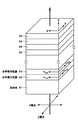
図2は、光学異方成膜32と光学等方性膜33とを支持体31上に交互に積層させてなる反射偏光子の一構成例を示す断面図である。図2において、n1x、n1yはそれぞれ、光学異方性膜32のx軸方向の屈折率、y軸方向の屈折率を示す。また、n2x、n2yはそれぞれ、光学等方性膜33のx軸方向の屈折率、y軸方向の屈折率を示す。
FIG. 2 is a cross-sectional view showing a configuration example of a reflective polarizer in which the optical
図2に示すように、この反射偏光子は、光学異方性膜32と光学等方性膜33とを支持体31上に交互に積層してなる。この反射偏光子は、反射偏光子に入射する光のうち、x偏光成分を透過するのに対して、y偏光成分を反射する。なお、以下では、支持体31において、光学異方性膜32および光学等方性膜33が積層される側の一主面を、成膜面と称する。
As shown in FIG. 2, this reflective polarizer is formed by alternately laminating optical
光学異方性膜32は、x軸方向とy軸方向とで異なる屈折率、すなわち複屈折を有する。一方、光学等方性膜33は、x軸方向とy軸方向とで等しい屈折率を有する。光学異方性膜32および光学等方性膜33のx軸方向の屈折率n1x、n2xおよびy軸方向の屈折率n1y、n2yと、y軸方向の膜間の屈折率差Δnとは、例えば、以下の関係を満たす。
n1x>n1y、n2x=n2y
n1x=n2x、n1y<n2y
Δn=n2y−n1y
The optically
n 1x > n 1y , n 2x = n 2y
n 1x = n 2x , n 1y <n 2y
Δn = n 2y −n 1y
第1の光学異方性膜32は、支持体31の成膜面に対して、y軸方向から斜めに無機材料を入射させてなる膜、すなわち、y軸方向に向けて斜めに無機材料を成長してなる斜方成長膜であり、例えば、y軸方向に傾いた柱状構造、または、粒状体を堆積した構造を有する。
The first optically
第2の光学等方性膜33は、支持体31の成膜面に対して、光軸の方向から垂直に無機材料を入射させてなる膜、すなわち、z軸方向に向けて垂直に無機材料を成長してなる膜であり、例えば、支持体31の成膜面に垂直な柱状構造、または、面内均一な構造を有する。
The second optically
ここで、例として具体的数値を用いて光学異方性膜32および光学等方性膜33について説明する。光学異方性膜32は、例えば、x軸方向の屈折率として屈折率n1x=2.0、y軸方向の屈折率として屈折率n1y=1.8を有する。光学等方性膜33は、例えば、x軸方向の屈折率として屈折率n2x=2.0、y軸方向の屈折率として屈折率n2y=2.0を有する。この場合、x軸方向においては、膜間の屈折率差はΔn=2.0−2.0=0となるのに対して、y軸方向においては、膜間の屈折率差はΔn=2.0−1.8=0.2となる。これらの光学特性により、多層の積層体が、入射光のy偏光成分のみを反射し、x偏光成分を透過する反射偏光子として機能することになる。
Here, the optical
可視光帯域をカバーするために必要な積層数は、膜間の屈折率差Δnの値により規定される。しかしながら、光学異方性膜32と光学等方性膜33とを積層する構成では、この膜間の屈折率差Δnをあまり大きくすることはできず、例えば膜間の屈折率差がΔn=0.2である場合には、200層以上の積層数が必要となってしまう。このための、上述の構成を有する反射偏光子では、更なる反射偏光子の薄型化、コンパクト化および生産性の向上が困難となっていた。
The number of layers required for covering the visible light band is defined by the value of the refractive index difference Δn between the films. However, in the configuration in which the optically
そこで、この発明の一実施形態による反射偏光子では、上述の反射偏光子よりも膜間の屈折率差Δnを更に大きくすることで、光学薄膜の積層数を更に低減して、更なる反射偏光子の薄型化、コンパクト化および生産性の向上を実現するものである。 Therefore, in the reflective polarizer according to an embodiment of the present invention, the refractive index difference Δn between the films is further increased as compared with the above-described reflective polarizer, thereby further reducing the number of laminated optical thin films and further reflecting polarized light. This makes it possible to make the child thinner, more compact, and improve productivity.
図3は、この発明の一実施形態による反射偏光子24の一構成例を示す断面図である。図3において、n1x、n1yはそれぞれ、第1の光学異方性膜42のx軸方向の屈折率、y軸方向の屈折率を示す。また、n2x、n2yはそれぞれ、第2の光学異方性膜43のx軸方向の屈折率、y軸方向の屈折率を示す。
FIG. 3 is a cross-sectional view showing a configuration example of the
図3に示すように、この反射偏光子24は、第1の光学異方性膜42と第2の光学異方性膜43とを支持体41上に交互に積層してなる。この反射偏光子24は、反射偏光子24に入射する光のうち、x偏光成分を透過するのに対して、y偏光成分を反射する。なお、以下では、支持体41において、第1の光学異方性膜42および第2の光学異方性膜43が積層される側の一主面を、成膜面と称する。
As shown in FIG. 3, the
支持体41は、透明性を有する基板またはフィルムである。支持体41の材料としては、透明性を有するガラスまたはプラスチック等を用いることができる。ガラスとしては、例えば、ソーダライムガラス、鉛ガラス、硬質ガラス、石英ガラスまたは液晶化ガラス等を用いることができる。プラスチックとしては、例えば、ポリカーボネート、ポリオレフィンまたはアクリル樹脂等を用いることができる。
The
第1の光学異方性膜42および第2の光学異方性膜43は、x軸方向とy軸方向とで異なる屈折率、すなわち複屈折を有する。第1の光学異方性膜42および第2の光学異方性膜43のx軸方向の屈折率n1x、n2xおよびy軸方向の屈折率n1y、n2yと、y軸方向の膜間の屈折率差Δnとは、例えば、以下の関係を満たす。
n1x>n1y、n2x<n2y
n1x=n2x、n1y<n2y
Δn=n2y−n1y
The first optical
n 1x > n 1y , n 2x <n 2y
n 1x = n 2x , n 1y <n 2y
Δn = n 2y −n 1y
この関係を満たすことにより、反射偏光子24に入射する光のうち、x軸方向に振動するx偏光成分を透過するの対して、y軸方向に振動するy偏光成分を反射することができる。また、y軸方向の膜間の屈折率差Δnを大きくすることができ、積層数を低減することができる。
By satisfying this relationship, it is possible to reflect the y-polarized component oscillating in the y-axis direction while transmitting the x-polarized component oscillating in the x-axis direction among the light incident on the
第1の光学異方性膜42の光学軸は、例えばy軸方向に傾いている。第2の光学異方成膜43の光学軸は、例えばx軸方向に傾いている。具体的には例えば、第2の光学異方性膜43の光学軸は、第1の光学異方性膜42の光学軸を、光軸を軸としてほぼ90度回転した位置にある。したがって、光軸方向から入射する光に対する屈折率楕円体切断面の長軸と短軸との位置関係が、第1の光学異方性膜42と第2の光学異方性膜43とでは反転している。
The optical axis of the first optical
図4Aおよび図4Bは、第1の光学異方性膜42および第2の光学異方性膜43の成膜方法を説明するための斜視図である。図4Aおよび図4Bにおいて、矢印の方向は、誘電体材料等の無機材料の入射方向を示す。
4A and 4B are perspective views for explaining a method of forming the first optical
第1の光学異方性膜42は、支持体41の成膜面に対して、y軸方向から斜めに無機材料を入射させてなる膜、すなわち、y軸方向に向けて斜めに無機材料を成長してなる斜方成長膜であり、例えば、y軸方向に傾いた柱状構造、または、粒状体を堆積した構造を有する。第2の光学異方性膜43は、支持体41の成膜面に対して、x軸方向から斜めに無機材料を入射させてなる膜、すなわち、x軸方向に向けて斜めに無機材料を成長してなる斜方成長膜であり、例えば、x軸方向に傾いた柱状構造、または、粒状体を堆積した構造を有する。
The first optically
このように、支持体41の成膜面に対して斜め方向に誘電体材料等からなる無機薄膜を成長させると、その特有の内部構造のために、支持体41の面内方位に対して光学異方性を発現させることができる(特開昭59−49508号公報参照)。
As described above, when an inorganic thin film made of a dielectric material or the like is grown in an oblique direction with respect to the film formation surface of the
第1の光学異方性膜42および第2の光学異方性膜43の有する構造は、材料等を適宜選択することにより作り分けることができる。例えば、斜め方向に成長した柱状構造は、Ta2O5を、支持体41の成膜面に対して斜めの方向から入射させることにより得ることができる。また、粒状体を堆積した構造は、例えば、Ta2O5とCeO2との混合物を、支持体41の成膜面に対して斜めの方向から入射させることにより得ることができる。
The structure possessed by the first optical
ここで、例として具体的数値を用いて第1の光学異方性膜42および第2の光学異方性膜43について説明する。第1の光学異方性膜42は、例えば、x軸方向の屈折率として屈折率n1x=1.8、y軸方向の屈折率として屈折率n1y=1.6を有する。第2の光学異方性膜43は、例えば、x軸方向の屈折率として屈折率n2x=1.8、y軸方向の屈折率としてn2y=2.0を有する。この場合、x軸方向における膜間の屈折率差はΔn=1.8−1.8=0となるのに対して、y軸方向における膜間の屈折率差はΔn=2.0−1.6=0.4となる。このように、y軸方向について大きな屈折率差Δnを得ることができるので、一方の偏光成分を透過するのに対して、もう一方の偏光成分を反射する反射偏光子としての機能を100層程度の積層数により得ることができる。すなわち、必要層数を大幅に低減することができる。
Here, the first optical
第1の光学異方性膜42および第2の光学異方性膜43は、例えば、異なる無機材料からなる。この無機材料としては、透明性を有する無機材料、例えば、透明性を有する誘電体材料を用いることができ、より具体的には例えば透明性を有する酸化物、硫化物またはフッ化物等を用いることができる。
The first optical
酸化物としては、例えば、タンタル(Ta)、チタン(Ti)、ジルコニウム(Zr)、ニオブ(Nb)、セリウム(Ce)、アルミニウム(Al)、珪素(Si)または亜鉛(Zn)の酸化物またはそれらの混合物を用いることができ、より具体的には例えば、五酸化タンタル(Ta2O5)、五酸化三チタン(Ti3O5)、三酸化二チタン(Ti2O3)、一酸化チタン(TiO)、二酸化チタン(TiO2)、二酸化ジルコニウム(ZrO2)、五酸化ニオブ(Nb2O5)、二酸化セリウム(CeO2)、酸化アルミニウム(Al2O3)、二酸化珪素(SiO2)、一酸化珪素(SiO)、ZnO(酸化亜鉛)またはそれらの混合物を用いることができる。 Examples of the oxide include an oxide of tantalum (Ta), titanium (Ti), zirconium (Zr), niobium (Nb), cerium (Ce), aluminum (Al), silicon (Si), or zinc (Zn) or A mixture thereof can be used, and more specifically, for example, tantalum pentoxide (Ta 2 O 5 ), trititanium pentoxide (Ti 3 O 5 ), dititanium trioxide (Ti 2 O 3 ), monoxide titanium (TiO), titanium dioxide (TiO 2), zirconium dioxide (ZrO 2), niobium pentoxide (Nb 2 O 5), cerium dioxide (CeO 2), aluminum oxide (Al 2 O 3), silicon dioxide (SiO 2 ), Silicon monoxide (SiO), ZnO (zinc oxide), or a mixture thereof.
硫化物としては、例えば、亜鉛(Zn)またはカドミウム(Cd)の硫化物またはそれらの混合物を用いることができ、より具体的には例えば、硫化亜鉛(ZnS)、硫化カドミウム(CdS)またはそれらの混合物を用いることができる。フッ化物としては、マグネシウム(Mg)、セリウム(Ce)、バリウム(Ba)、カルシウム(Ca)またはネオジウム(Nd)のフッ化物またはそれらの混合物を用いることができ、より具体的には例えば、フッ化マグネシウム(MgF2)、フッ化セリウム(CeF3)、フッ化バリウム(BaF2)、フッ化カルシウム(CaF2)、フッ化ネオジム(NdF3)またはそれらの混合物を用いることができる。 As the sulfide, for example, a sulfide of zinc (Zn) or cadmium (Cd) or a mixture thereof can be used, and more specifically, for example, zinc sulfide (ZnS), cadmium sulfide (CdS) or a mixture thereof. Mixtures can be used. As the fluoride, a fluoride of magnesium (Mg), cerium (Ce), barium (Ba), calcium (Ca) or neodymium (Nd) or a mixture thereof can be used, and more specifically, for example, fluoride. Magnesium fluoride (MgF 2 ), cerium fluoride (CeF 3 ), barium fluoride (BaF 2 ), calcium fluoride (CaF 2 ), neodymium fluoride (NdF 3 ), or a mixture thereof can be used.
第1の光学異方性膜42と第2の光学異方性膜43とを構成する無機材料は、y軸方向について膜間の屈折率差Δnが大きくなるように選ぶことが好ましい。屈折率差Δnは、例えば0.05以上、好ましくは0.2以上、より好ましくは0.44以上に選ばれる。屈折率差Δnを0.2以上にすることにより、可視光帯域全域で一方の偏光の反射率を97%以上とするために必要な積層数を200層以下とすることができる。屈折率差Δnを0.44以上にすることにより、可視光帯域全域で一方の偏光の反射率を97%以上とするために必要な積層数を100層以下とすることができる。
The inorganic material constituting the first optical
このように膜間の屈折率差Δnを大きくするためには、第1の光学異方性膜42を構成する酸化物として、例えば、二酸化セリウム(CeO2)、五酸化タンタル(Ta2O5)、五酸化ニオブ(Nb2O5)または酸化亜鉛(ZnO)を用い、第2の光学異方性膜43を構成する酸化物としては、例えば、二酸化チタン(TiO2)を用いるようにする。
In order to increase the refractive index difference Δn between the films as described above, examples of oxides constituting the first optical
反射偏光子24の光学性能は、各々の光学膜の光学的厚み(屈折率×厚み)により決定される。光学膜が光の波長よりも小さな光学的厚みを有する場合には、選択波長における反射偏光子24の光学性能を高めるために、構造的干渉を利用することができる。なお、光の波長よりも薄い光学的厚さを有する均一な膜を成膜するための成膜方法としては、例えば真空薄膜形成技術を用いることができる。真空薄膜形成技術としては、例えば、スパッタリング法、化学気相成長法、真空蒸着法またはイオンプレーティング法等を用いることができる。
The optical performance of the
具体的には、構造的干渉は、対になった光学膜の光学的厚さ(第1の光学異方性膜42の光学的厚さ+第2の光学異方性膜43の光学的厚さ)が、入射光の波長の半分となる場合に生じる。この半波長の条件により、設計波長λを中心とした狭帯域の構造的干渉が生じる。広帯域の光学性能は、複数の狭い帯域の組み合わせを積層することによって得ることができる。例えば、同じ厚さ(第1の光学異方性膜42の光学的厚さ+第2の光学異方性膜43の光学的厚さ=λ/2)を有する第1グループを、異なる厚さ(第1の光学異方性膜42の光学的厚さ+第2の光学異方性膜43の光学的厚さ=λ’/2)を有する第2のグループに積層することにより、λとλ’を中心にした2種類の帯域が組み合わさり、広帯域化する。
Specifically, the structural interference is caused by the optical thickness of the paired optical films (the optical thickness of the first optical
例えば、広帯域の光学特性を得るために、膜厚d1を有する第1の光学異方性膜42および第2の光学異方性膜43を交互に積層してなる第1の積層体、膜厚d2を有する第1の光学異方性膜42および第2の光学異方性膜43を交互に積層してなる第2の積層体、・・・、膜厚dnを有する第1の光学異方性膜42および第2の光学異方性膜43を交互に積層してなる第nの積層体を支持体41上に順次積層するようにする。ここで、膜厚d1、d2、・・・、dnは、所望とする帯域に応じて適宜選択される。
For example, in order to obtain broadband optical characteristics, a first laminated body and a film obtained by alternately laminating first optical
より具体的には例えば、バックライト7から出射された白色光をカバーする広帯域の光学特性を得るためには、膜厚d1を有する第1の光学異方性膜42および第2の光学異方性膜43を交互に積層してなる第1の積層体、膜厚d2を有する第1の光学異方性膜42および第2の光学異方性膜43を交互に積層してなる第2の積層体、膜厚d3を有する第1の光学異方性膜42および第2の光学異方性膜43を交互に積層してなる第3の積層体、膜厚d4を有する第1の光学異方性膜42および第2の光学異方性膜43を交互に積層してなる第4の積層体を支持体41上に順次積層するようにすることが好ましい。ここで、膜厚d1、d2、d3、d4は、白色光に対応する帯域に応じて適宜選択される。
More specifically, for example, in order to obtain a broadband optical characteristic covering white light emitted from the backlight 7, the first optical
図5は、柱状構造を有する反射偏光子24のxz平面における断面図である。図6は、柱状構造を有する反射偏光子24のyz平面における断面図である。なお、図5および図6では、便宜上、第1の光学異方性膜42および第2の光学異方性膜43の積層数が4層である場合を例として示している。
FIG. 5 is a cross-sectional view of the
第1の光学異方性膜42は、x軸に対して垂直で、y軸に対して傾いて成長した柱状構造からなる。このように柱状構造を斜方成長させることにより光学異方性を得ることができ、具体的には、x軸方向の屈折率n1xよりもy軸方向の屈折率n1yを小さくすることができる。第1の光学異方性膜42の柱状構造は、例えば、支持体41の成膜面の法線(すなわちz軸)を基準としてy軸方向に向けて5度以上85度以下の範囲で傾いている。
The first optical
第2の光学等方性膜43は、x軸に対して傾き、y軸に対して垂直に成長した柱状構造からなる。このように柱状構造を斜方成長させることにより光学異方性を得ることができ、具体劇には、x軸方向の屈折率n2xよりもy軸方向の屈折率n2yを大きくすることができる。第2の光学異方性膜43の柱状構造は、例えば、支持体41の成膜面の法線(すなわちz軸)を基準としてx軸方向に向けて5度以上85度以下の範囲で傾いている。
The second optically
(3)反射偏光子の製造装置
図7は、この発明の一実施形態による反射偏光子の製造装置101の一構成例を示す模式図である。図8は、図7の紙面に平行な概略断面図である。なお、図9は、図7のIX−IX線における概略断面図である。この反射偏光子の製造装置101は、第1の光学異方性膜42と第2の光学異方性膜43とを交互に支持体41上に積層することができるスパッタリング装置である。
(3) Reflective Polarizer Manufacturing Apparatus FIG. 7 is a schematic diagram showing a configuration example of a reflective
以下、図7〜図9を参照しながら、この発明の一実施形態による反射偏光子の製造装置101の構成について説明する。図7に示すように、この反射偏光子の製造装置101は、真空室103を有し、この真空室103の側面部には真空排気系102が設けられている。この真空排気系102により、真空室103の内部が高真空状態とされる。
Hereinafter, the configuration of the reflective
また、真空室103の内部には、ガイドロール104,105と、張力調整ロール106,107と、冷却キャン108とが設けられている。これらのガイドロール104、105、張力調整ロール106、107および冷却キャン108により、支持体41は、例えば反時計回りの方向に走行される。なお、帯状の支持体41は、その長手方向の両端部を、例えば粘着テープによりつなぎ合わされてリング状の状態とされ、冷却キャン108に装着される。
Inside the
冷却キャン108は回転可能に構成され、この冷却キャン108の回転に伴って支持体41は、冷却キャン108の周面を定速度で走行される。この冷却キャン108の内部には図示しない冷却機構が設けられ、この冷却機構が、外部の図示しない冷却装置により冷却される。これにより、支持体41の温度上昇による変形等を抑制することができる。
The cooling can 108 is configured to be rotatable, and the
張力調整ロール106,107は、支持体41が変形することなく円滑に走行するように、支持体41の張力を制御する。この張力調整ロール106、107は、図示しない張力調整機構によって適宜制御されるようになっている。なお、ガイドロール104、105、張力調整ロール106、107、冷却キャン108は、例えば、支持体41の幅よりも大きい円筒状を有する。
The tension adjusting rolls 106 and 107 control the tension of the
また、真空室103の内部には、第1の気化源である第1のターゲット109と、第2の気化源である第2のターゲット110とが設けられている。第1のターゲット109および第2のターゲット110としては、酸化物ターゲットまたは金属ターゲットを用いることができる。金属ターゲットを用いる場合には、DCスパッタリング法、ACスパッタリング法等を用いることも可能である。また、成膜速度の点からすると、金属ターゲットを用いることが好ましい。
In the
第1のターゲット109は、冷却キャン108の周面を定速度で走行する支持体41に対して第1の光学異方性膜42を形成するためのものであり、この第1のターゲット109は、第1の光学異方性膜42に応じた材料から構成される。
The
第2のターゲット110は、冷却キャン108の周面を定速度で走行する支持体41に対して第2の光学異方性膜43を形成するためのものであり、この第2のターゲット110は、第2の光学異方性膜43に応じた材料から構成される。
The
図8に示すように、第1のターゲット109は、この第1のターゲット109から弾き出されたスパッタ原子が、冷却キャン108の走行面に対して走行方向またはその逆方向から斜めに入射するように設けられている。スパッタ原子は、例えば、冷却キャン108の走行面の法線nから走行方向またはその逆方向に角度θ傾いた方向から入射する。ここで、角度θは、例えば5度以上85度以下の範囲から選ばれる。このようにスパッタ原子を入射させることにより、支持体41の成膜面上に斜めに無機材料110を成長させることができる。
As shown in FIG. 8, the
図9に示すように、第2のターゲット110は、この第2のターゲット110から弾き出されたスパッタ原子が、冷却キャン108の走行面に対して側方から斜めに入射するように設けられている。スパッタ原子は、例えば、冷却キャン108の走行面の法線nから側方に角度θ傾いた方向から入射する。ここで、角度θは、例えば5度以上85度以下の範囲から選ばれる。このようにスパッタ原子を入射させることにより、支持体41の成膜面上に斜めに無機材料110を成長させることができる。
As shown in FIG. 9, the
また、冷却キャン108と第1のターゲット109との間には、冷却キャン108の近傍にシャッタ111aおよびシャッタ111bが設けられている。このシャッタ111aおよびシャッタ111bは、冷却キャン108の周面を定速度で走行する支持体41の所定領域を覆うように設けられている。このシャッタ111aおよびシャッタ111bにより、第1のターゲット109から飛び出したスパッタリング原子を支持体41上に対して所定の角度範囲で斜めに入射させることができる。
Further, between the cooling can 108 and the
また、冷却キャン108と第2のターゲット110との間には、冷却キャン108の近傍にシャッタ111aおよびシャッタ111cが設けられている。このシャッタ111aおよびシャッタ111cは、冷却キャン108の周面を定速度で走行する支持体41の所定領域を覆うように設けられている。このシャッタ111aおよびシャッタ111cにより、第2のターゲット110から飛び出したスパッタリング原子を支持体41上に対して所定の角度範囲で斜めに入射させることができる。
In addition, a
(4)反射偏光子の製造方法
次に、この発明の一実施形態による反射偏光子の製造方法について説明する。
(4) Manufacturing method of reflective polarizer Next, the manufacturing method of the reflective polarizer by one Embodiment of this invention is demonstrated.
まず、帯状を有する支持体41の長手方向の両端部を、例えば粘着テープによりつなぎ合わせてリング状として、冷却キャン108に装着する。次に、真空排気系102により真空室103内を所定の真空度まで真空引きした後、冷却キャン108により支持体41を定速度で走行させる。
First, both ends in the longitudinal direction of the
次に、支持体41を一定の速度で走行させながら、放電ガスを真空室103内に導入し、スパッタリングを行うことにより、第1の光学異方性膜42と第2の光学異方性膜43とを支持体41上に交互に積層する。ここで、各膜の膜厚、屈折率および屈折率差Δnは成膜条件により制御可能である。以上により、目的とする反射偏光子24を得ることができる。
Next, the first optical
この発明の一実施形態によれば以下の効果を得ることができる。
第1の光学異方性膜42および第2の光学異方性膜43を交互に積層して反射偏光子24を作製するので、光学異方性膜と光学等方性膜とを交互に積層した反射偏光子に比べて、膜間の屈折率差Δnをより大きくすることができるので、可視光帯域を反射するために必要な層数を低減することができる。したがって、生産性の向上およびコストの削減を実現できる。
According to one embodiment of the present invention, the following effects can be obtained.
Since the
また、第1の光学異方性膜42および第2の光学異方成膜43は、誘電体材料等の無機材料から構成されるので、有機物特有の紫外線劣化や熱による変形等がなく、優れた耐候性を実現できる。また、有機材料からなる光学薄膜を積層した反射偏光子のように、紫外線帯域の光を吸収することがないので、青色光の透過率が低下することもない。したがって、可視光対全域にわたり高い透過性を有する。また、他の光学薄膜への複合化、例えば、偏光板との複合化等が容易である。
Further, since the first optical
また、無機材料を支持体41に対して入射させて、第1の光学異方性膜42および第2の光学異方成膜43を積層するので、延伸フィルム特有の軸方向の場所ムラや、膜厚のムラによる位相差設定の精度の低下がない。したがって、反射偏光子の膜厚をナノオーダで制御することができる。また、軸方向の場所ムラのない異方性薄膜を得ることができるので、成膜時間による精度の高い位相差設定が可能となる。また、入射角度依存性の小さい高性能反射偏光子を作成することができる。また、可視光全域にわたり高性能偏光分離特性を得ることができる。
Also, since the first optical
以下、実施例により本発明を具体的に説明するが、本発明はこれらの実施例のみに限定されるものではない。なお、以下の実施例および比較例では、透明支持体41の面内方向を、図3に示した座標系を用いて説明する。
EXAMPLES Hereinafter, although an Example demonstrates this invention concretely, this invention is not limited only to these Examples. In the following examples and comparative examples, the in-plane direction of the
実施例1
スパッタリングによりy軸方向から斜めにスパッタ原子を成膜面に対して入射させて、CeO2からなる第1の光学異方性膜42を成膜する工程と、スパッタリングによりx軸方向から斜めにスパッタ原子を成膜面に対して入射させて、TiO2からなる第2の光学異方性膜42を成膜する工程とを交互に繰り返して、透明支持体41上に積層体を形成して、可視光帯域全域でy軸方向の偏光の反射率が97%以上となるために必要な層数を評価した。
Example 1
Sputtering atoms are incident on the film formation surface obliquely from the y-axis direction by sputtering, and a first optical
実施例2
スパッタリングによりy軸方向から斜めにスパッタ原子を成膜面に対して入射させて、Ta2O5からなる第1の光学異方性膜42を成膜する工程と、スパッタリングによりx軸方向から斜めにスパッタ原子を成膜面に対して入射させて、TiO2からなる第2の光学異方性膜42を成膜する工程とを交互に繰り返して、透明支持体41上に積層体を形成して、可視光帯域全域でy軸方向の偏光の反射率が97%以上となるために必要な層数を評価した。
Example 2
Sputtering atoms are incident on the film formation surface obliquely from the y-axis direction by sputtering to form the first optical
実施例3
スパッタリングによりy軸方向から斜めにスパッタ原子を成膜面に対して入射させて、Nb2O5からなる第1の光学異方性膜42を成膜する工程とスパッタリングによりx軸方向から斜めにスパッタ原子を成膜面に対して入射させて、TiO2からなる第2の光学異方性膜42を成膜する工程とを交互に繰り返して、透明支持体41上に積層体を形成して、可視光帯域全域でy軸方向の偏光の反射率が97%以上となるために必要な層数を評価した。
Example 3
Sputtering atoms are incident on the film formation surface obliquely from the y-axis direction by sputtering, and the first optical
実施例4
スパッタリングによりy軸方向から斜めにスパッタ原子を成膜面に対して入射させて、ZnOからなる第1の光学異方性膜42を成膜する工程と、スパッタリングによりx軸方向から斜めにスパッタ原子を成膜面に対して入射させて、TiO2からなる第2の光学異方性膜42を成膜する工程とを交互に繰り返して、透明支持体41上に積層体を形成して、可視光帯域全域でy軸方向の偏光の反射率が97%以上となるために必要な層数を評価した。
Example 4
Sputtering atoms are incident on the film formation surface obliquely from the y-axis direction by sputtering, and a first optical
実施例5
スパッタリングによりy軸方向から斜めにスパッタ原子を成膜面に対して入射させて、Nb2O5からなる第1の光学異方性膜42を成膜する工程と、スパッタリングによりx軸方向から斜めにスパッタ原子を成膜面に対して入射させて、CeO2からなる第2の光学異方性膜42を成膜する工程とを交互に繰り返して、透明支持体41上に積層体を形成して、可視光帯域全域でy軸方向の偏光の反射率が97%以上となるために必要な層数を評価した。
Example 5
Sputtering atoms are incident on the film formation surface obliquely from the y-axis direction by sputtering, and the first optical
比較例1
スパッタリングによりy軸方向から斜めにスパッタ原子を成膜面に対して入射させて、Ta2O5からなる第1の光学異方性膜42を成膜する工程と、スパッタリングによりx軸方向から斜めにスパッタ原子を成膜面に対して入射させて、CeO2からなる第2の光学異方性膜42を成膜する工程とを交互に繰り返して、透明支持体41上に積層体を形成して、可視光帯域全域でy軸方向の偏光の反射率が97%以上となるために必要な層数を評価した。
Comparative Example 1
Sputtering atoms are incident on the film formation surface obliquely from the y-axis direction by sputtering to form the first optical
比較例2
スパッタリングによりy軸方向から斜めにスパッタ原子を成膜面に対して入射させて、Ta2O5からなる光学異方性膜42を成膜する工程と、スパッタリングによりz軸方向から垂直にスパッタ原子を成膜面に対して入射させて、Ta2O5からなる光学等方性膜を成膜する工程とを交互に繰り返して、透明支持体41上に積層体を形成して、可視光帯域全域でy軸方向の偏光の反射率が97%以上となるために必要な層数を評価した。
Comparative Example 2
Sputtering atoms are incident on the deposition surface obliquely from the y-axis direction by sputtering to form an optically
また、上述の実施例および比較例の第1の光学異方性膜42の屈折率(n1x,n1y)、第2の光学異方性膜43の屈折率(n2x,n2y)、y軸方向の膜間の屈折率差Δn(=n2y−n1y)についても評価した。なお、屈折率の測定には、分光エリプソメーター(J・A WOOLLAM JAPAN社製、商品名:M−2000)を用いた。表1に、実施例および比較例による反射偏光子の膜構成、屈折率および必要層数を示す。
Further, the refractive index (n 1x , n 1y ) of the first optical

表1から以下のことが分かる。
(1)第1の光学異方性膜および第2の光学異方性膜を透明支持体上に積層した実施例1〜5では、光学異方性膜および光学等方性膜を透明支持体上に積層した比較例1、2に比べて、屈折率差Δnをより大きくすることができ、必要層数を低減できることが分かる。
(2)実施例1〜5では、膜間におけるy軸方向の屈折率差Δnを0.2以上にすることができ、可視光帯域全域でy軸方向の偏光の反射率を97%以上とするために必要な積層数を200層以下に低減できることが分かる。すなわち、必要層数を従来に比して低減できることが分かる。
(3)実施例1、実施例2および実施例4では、膜間におけるy軸方向の屈折率差Δnを0.44以上にすることができ、可視光帯域全域でy軸方向の偏光の反射率を97%以上とするために必要な積層数を100層以下に低減できることが分かる。すなわち、必要層数を従来に比して大幅に低減できることが分かる。
Table 1 shows the following.
(1) In Examples 1 to 5 in which the first optical anisotropic film and the second optical anisotropic film are laminated on the transparent support, the optical anisotropic film and the optical isotropic film are used as the transparent support. It can be seen that the refractive index difference Δn can be further increased and the required number of layers can be reduced as compared with Comparative Examples 1 and 2 stacked above.
(2) In Examples 1 to 5, the refractive index difference Δn between the films in the y-axis direction can be 0.2 or more, and the reflectance of polarized light in the y-axis direction is 97% or more over the entire visible light band. It can be seen that the number of layers required for the reduction can be reduced to 200 layers or less. That is, it can be seen that the required number of layers can be reduced as compared with the conventional case.
(3) In Example 1, Example 2, and Example 4, the refractive index difference Δn in the y-axis direction between the films can be 0.44 or more, and the reflection of polarized light in the y-axis direction over the entire visible light band. It can be seen that the number of stacked layers required for the rate to be 97% or more can be reduced to 100 layers or less. That is, it can be seen that the required number of layers can be greatly reduced as compared with the conventional case.
以上、この発明の一実施形態について具体的に説明したが、この発明は、上述の一実施形態に限定されるものではなく、この発明の技術的思想に基づく各種の変形が可能である。 The embodiment of the present invention has been specifically described above, but the present invention is not limited to the above-described embodiment, and various modifications based on the technical idea of the present invention are possible.
例えば、上述の一実施形態において挙げた数値はあくまでも例に過ぎず、必要に応じてこれと異なる数値を用いてもよい。 For example, the numerical values given in the above-described embodiment are merely examples, and different numerical values may be used as necessary.
また、上述の一実施形態においては、第1の光学異方性膜42および第2の光学異方性膜43を無機材料から構成する場合を例として示したが、第1の光学異方性膜42および第2の光学異方性膜43を有機材料から構成するようにしてもよい。この場合、第1の光学異方性膜42および第2の光学異方性膜43としては、例えば、ポリエチレンナフタレート(PEN)等の結晶質のナフタリンジカルボン酸ポリエステルからなる一軸延伸シートを用いることができる。
Further, in the above-described embodiment, the case where the first optical
1 液晶表示装置
2 液晶パネル
3 第1の基板
4 第2の基板
5 スペーサ
6 液晶層
7 バックライト
24 反射偏光子
41 支持体
42 光学異方性膜
43 光学等方性膜
101 反射偏光子の製造装置
108 冷却キャン
109,110 ターゲット
DESCRIPTION OF SYMBOLS 1 Liquid
Claims (12)
上記第1および第2の光学異方性膜とは、互いに直行する面内方向のうち一方の面内方向には等しい屈折率を有するのに対して、他方の面内方向には異なる屈折率を有し、
上記第1の光学異方性膜では、上記一方の面内方向の屈折率より上記他方の面内方向の屈折率が小さく、
上記第2の光学異方性膜では、上記一方の面内方向の屈折率より上記他方の面内方向の屈折率が大きく、
上記第1の光学異方性膜は、上記透明支持体の一主面に対して上記他方の面内方向に傾いた柱状構造を有し、
上記第2の光学異方性膜は、上記透明支持体の一主面に対して上記一方の面内方向に傾いた柱状構造を有する
ことを特徴とする反射偏光子。 A transparent support, and a first optical anisotropic film and a second optical anisotropic film laminated alternately on the transparent support,
Said the first and second optically anisotropic layer, different for to have an equal correct refractive index on one surface in the direction of the plane direction orthogonal to each other, the other in-plane direction refraction Have a rate,
In the first optical anisotropic film, the refractive index in the other in-plane direction is smaller than the refractive index in the one in-plane direction,
In the second optical anisotropic film, the refractive index in the other in-plane direction is larger than the refractive index in the one in-plane direction,
The first optical anisotropic film has a columnar structure inclined in the other in-plane direction with respect to one main surface of the transparent support,
The reflective polarizer, wherein the second optically anisotropic film has a columnar structure inclined in the one in-plane direction with respect to one main surface of the transparent support.
上記第2の光学異方性膜は、上記透明支持体の一主面に対して上記一方の面内方向から斜めに無機材料を入射してなる光学異方性膜である
ことを特徴とする請求項1記載の反射偏光子。 The first optical anisotropic film is an optical anisotropic film formed by injecting an inorganic material obliquely from the other in-plane direction with respect to one main surface of the transparent support,
The second optically anisotropic film is an optically anisotropic film formed by injecting an inorganic material obliquely from the one in-plane direction with respect to one main surface of the transparent support. The reflective polarizer according to claim 1 .
第2の気化源を用いて、上記透明支持体の一主面に対して、上記互いに直行する面内方向のうち他方の面内方向から斜めに無機材料を入射させる工程と、
を交互に繰り返すことにより、第1の光学異方性膜と第2の光学異方性膜とが交互に繰り返し積層され、
上記第1の光学異方性膜は、上記透明支持体の一主面に対して上記他方の面内方向に傾いた柱状構造を有し、
上記第2の光学異方性膜は、上記透明支持体の一主面に対して上記一方の面内方向に傾いた柱状構造を有する
ことを特徴とする反射偏光子の製造方法。 Using the first vaporization source, the step of causing the inorganic material to enter obliquely from one in-plane direction among the in-plane directions perpendicular to each other with respect to one main surface of the transparent support;
Injecting an inorganic material obliquely from the other in-plane direction among the in-plane directions perpendicular to each other with respect to one main surface of the transparent support using a second vaporization source;
By alternately repeating the steps , the first optical anisotropic film and the second optical anisotropic film are alternately and repeatedly stacked,
The first optical anisotropic film has a columnar structure inclined in the other in-plane direction with respect to one main surface of the transparent support,
The method for producing a reflective polarizer, wherein the second optically anisotropic film has a columnar structure inclined in the one in-plane direction with respect to one main surface of the transparent support .
上記走行手段により走行される透明支持体に対して、互いに直行する面内方向のうちの一方の面内方向から斜めに無機材料を入射させる第1の気化源と、
上記走行手段により走行される透明支持体に対して、互いに直行する面内方向のうちの他方の面内方向から斜めに無機材料を入射させる第2の気化源と、
を備え、
上記走行手段が、上記第1の気化源および第2の気化源上を上記透明支持体が周期的に通過するように、上記透明支持体を走行させることにより、第1の光学異方性膜と第2の光学異方性膜とが交互に繰り返し積層され、
上記第1の光学異方性膜は、上記透明支持体の一主面に対して上記他方の面内方向に傾いた柱状構造を有し、
上記第2の光学異方性膜は、上記透明支持体の一主面に対して上記一方の面内方向に傾いた柱状構造を有する
ことを特徴とする反射偏光子の製造装置。 Traveling means for traveling the transparent support;
A first vaporization source that causes the inorganic material to enter obliquely from one of the in-plane directions perpendicular to each other with respect to the transparent support that is traveled by the travel means;
A second vaporization source that causes the inorganic material to enter obliquely from the other in-plane direction of the in-plane directions perpendicular to each other, with respect to the transparent support that is traveled by the travel means;
With
The traveling means travels the transparent support so that the transparent support periodically passes over the first vaporization source and the second vaporization source, whereby the first optical anisotropic film And the second optically anisotropic film are alternately and repeatedly laminated,
The first optical anisotropic film has a columnar structure inclined in the other in-plane direction with respect to one main surface of the transparent support,
The apparatus for manufacturing a reflective polarizer, wherein the second optical anisotropic film has a columnar structure inclined in the one in-plane direction with respect to one main surface of the transparent support .
Priority Applications (1)
| Application Number | Priority Date | Filing Date | Title |
|---|---|---|---|
| JP2005054074A JP4595586B2 (en) | 2005-02-28 | 2005-02-28 | REFLECTIVE POLARIZER AND METHOD FOR MANUFACTURING THE SAME, APPARATUS FOR PRODUCING REFLECTIVE POLARIZER, AND LIQUID CRYSTAL DISPLAY |
Applications Claiming Priority (1)
| Application Number | Priority Date | Filing Date | Title |
|---|---|---|---|
| JP2005054074A JP4595586B2 (en) | 2005-02-28 | 2005-02-28 | REFLECTIVE POLARIZER AND METHOD FOR MANUFACTURING THE SAME, APPARATUS FOR PRODUCING REFLECTIVE POLARIZER, AND LIQUID CRYSTAL DISPLAY |
Publications (2)
| Publication Number | Publication Date |
|---|---|
| JP2006235543A JP2006235543A (en) | 2006-09-07 |
| JP4595586B2 true JP4595586B2 (en) | 2010-12-08 |
Family
ID=37043204
Family Applications (1)
| Application Number | Title | Priority Date | Filing Date |
|---|---|---|---|
| JP2005054074A Expired - Fee Related JP4595586B2 (en) | 2005-02-28 | 2005-02-28 | REFLECTIVE POLARIZER AND METHOD FOR MANUFACTURING THE SAME, APPARATUS FOR PRODUCING REFLECTIVE POLARIZER, AND LIQUID CRYSTAL DISPLAY |
Country Status (1)
| Country | Link |
|---|---|
| JP (1) | JP4595586B2 (en) |
Families Citing this family (2)
| Publication number | Priority date | Publication date | Assignee | Title |
|---|---|---|---|---|
| CN102628968B (en) * | 2012-01-04 | 2013-08-07 | 京东方科技集团股份有限公司 | Condensation film, backlight module and liquid crystal display panel |
| CN110632697B (en) * | 2019-09-24 | 2021-10-08 | 杭州灯之塔科技有限公司 | Polarizing element and preparation method thereof |
Citations (5)
| Publication number | Priority date | Publication date | Assignee | Title |
|---|---|---|---|---|
| JPS5949508A (en) * | 1982-09-14 | 1984-03-22 | Sony Corp | Production of double refractive plate |
| JPH1081955A (en) * | 1996-07-11 | 1998-03-31 | Toyota Central Res & Dev Lab Inc | Diagonally vapor deposited film element and optical device formed by using the same |
| JPH1123840A (en) * | 1997-06-30 | 1999-01-29 | Sumitomo Bakelite Co Ltd | Double refractive plate |
| JP2002514780A (en) * | 1998-05-13 | 2002-05-21 | スリーエム イノベイティブ プロパティズ カンパニー | Optical film having continuous phase and dispersed phase |
| JP3448626B2 (en) * | 1993-12-21 | 2003-09-22 | スリーエム イノベイティブ プロパティズ カンパニー | Reflective polarizer display |
-
2005
- 2005-02-28 JP JP2005054074A patent/JP4595586B2/en not_active Expired - Fee Related
Patent Citations (5)
| Publication number | Priority date | Publication date | Assignee | Title |
|---|---|---|---|---|
| JPS5949508A (en) * | 1982-09-14 | 1984-03-22 | Sony Corp | Production of double refractive plate |
| JP3448626B2 (en) * | 1993-12-21 | 2003-09-22 | スリーエム イノベイティブ プロパティズ カンパニー | Reflective polarizer display |
| JPH1081955A (en) * | 1996-07-11 | 1998-03-31 | Toyota Central Res & Dev Lab Inc | Diagonally vapor deposited film element and optical device formed by using the same |
| JPH1123840A (en) * | 1997-06-30 | 1999-01-29 | Sumitomo Bakelite Co Ltd | Double refractive plate |
| JP2002514780A (en) * | 1998-05-13 | 2002-05-21 | スリーエム イノベイティブ プロパティズ カンパニー | Optical film having continuous phase and dispersed phase |
Also Published As
| Publication number | Publication date |
|---|---|
| JP2006235543A (en) | 2006-09-07 |
Similar Documents
| Publication | Publication Date | Title |
|---|---|---|
| JP6735310B2 (en) | Polarizing plate and liquid crystal display device including the same | |
| US8558970B2 (en) | Display unit | |
| KR102418069B1 (en) | Image display mirror for a vehicle | |
| WO2010058633A1 (en) | Circularly polarizing plate and display device | |
| WO2014168185A1 (en) | Phase contrast compensation element and projection-type image projection device | |
| JPWO2011043098A1 (en) | Liquid crystal display | |
| WO2016080385A1 (en) | Liquid crystal display device | |
| US10207645B2 (en) | Vehicle including mirror with image display apparatus | |
| JP4928985B2 (en) | Liquid crystal display | |
| WO2015147287A1 (en) | Liquid crystal panel, liquid crystal display device, polarizing plate, and polarizing plate protective film | |
| JP2019204086A (en) | Optical laminate, display panel, and display device | |
| TW201842385A (en) | Phase difference film, circularly polarizing plate or elliptically polarizing plate, display panel, liquid crystal display panel, organic el display panel, display device, liquid crystal display device, and organic el display device | |
| US10718971B2 (en) | Display device | |
| CN110095833B (en) | Phase difference compensation element, liquid crystal display device, and projection type image display device | |
| WO2020087632A1 (en) | Optical composite film, display panel, and display device | |
| JP4595586B2 (en) | REFLECTIVE POLARIZER AND METHOD FOR MANUFACTURING THE SAME, APPARATUS FOR PRODUCING REFLECTIVE POLARIZER, AND LIQUID CRYSTAL DISPLAY | |
| WO2013111867A1 (en) | Liquid crystal display device | |
| JPH07181476A (en) | Liquid crystal display device | |
| US10317599B2 (en) | Wavelength plate and optical device | |
| TW201337349A (en) | Optical element and display system | |
| JP2007003626A (en) | Reflective polarizer, method and device for manufacturing same and liquid crystal display device | |
| US8369016B2 (en) | Optical sheet | |
| WO2018225631A1 (en) | Liquid crystal display device | |
| US9625762B2 (en) | Liquid crystal display device | |
| JP5207704B2 (en) | Liquid crystal display |
Legal Events
| Date | Code | Title | Description |
|---|---|---|---|
| A621 | Written request for application examination |
Free format text: JAPANESE INTERMEDIATE CODE: A621 Effective date: 20071029 |
|
| A977 | Report on retrieval |
Free format text: JAPANESE INTERMEDIATE CODE: A971007 Effective date: 20100125 |
|
| A131 | Notification of reasons for refusal |
Free format text: JAPANESE INTERMEDIATE CODE: A131 Effective date: 20100202 |
|
| A521 | Written amendment |
Free format text: JAPANESE INTERMEDIATE CODE: A523 Effective date: 20100405 |
|
| A131 | Notification of reasons for refusal |
Free format text: JAPANESE INTERMEDIATE CODE: A131 Effective date: 20100601 |
|
| A521 | Written amendment |
Free format text: JAPANESE INTERMEDIATE CODE: A523 Effective date: 20100802 |
|
| TRDD | Decision of grant or rejection written | ||
| A01 | Written decision to grant a patent or to grant a registration (utility model) |
Free format text: JAPANESE INTERMEDIATE CODE: A01 Effective date: 20100824 |
|
| A01 | Written decision to grant a patent or to grant a registration (utility model) |
Free format text: JAPANESE INTERMEDIATE CODE: A01 |
|
| A61 | First payment of annual fees (during grant procedure) |
Free format text: JAPANESE INTERMEDIATE CODE: A61 Effective date: 20100906 |
|
| FPAY | Renewal fee payment (event date is renewal date of database) |
Free format text: PAYMENT UNTIL: 20131001 Year of fee payment: 3 |
|
| LAPS | Cancellation because of no payment of annual fees |