JP4595109B2 - Game machine - Google Patents
Game machine Download PDFInfo
- Publication number
- JP4595109B2 JP4595109B2 JP2003394322A JP2003394322A JP4595109B2 JP 4595109 B2 JP4595109 B2 JP 4595109B2 JP 2003394322 A JP2003394322 A JP 2003394322A JP 2003394322 A JP2003394322 A JP 2003394322A JP 4595109 B2 JP4595109 B2 JP 4595109B2
- Authority
- JP
- Japan
- Prior art keywords
- blade
- movable body
- posture
- movable
- drive shaft
- Prior art date
- Legal status (The legal status is an assumption and is not a legal conclusion. Google has not performed a legal analysis and makes no representation as to the accuracy of the status listed.)
- Expired - Fee Related
Links
Images


Description
本発明は、可動体によって入賞確率を変えることができる可変入賞装置を備えた遊技機に関する。 The present invention relates to a gaming machine including a variable winning device that can change a winning probability by a movable body.
この種の遊技機に関する従来技術として、遊技領域のほぼ中央位置に可変入賞装置が配設されたパチンコ遊技機が挙げられる(例えば、特許文献1参照。)。可変入賞装置には左右一対の可動体(飛行機翼状の可動片)が設けられており、これら可動体は別の始動入賞口に遊技球が入賞することによって作動し、一定時間内だけ可変入賞装置の入賞口が開放された状態になる。そして、この間に入賞した遊技球がさらに可変入賞装置内の特定領域を通過すると、これを契機として特別遊技状態に移行する。 As a conventional technique related to this type of gaming machine, there is a pachinko gaming machine in which a variable winning device is disposed at a substantially central position of the gaming area (see, for example, Patent Document 1). The variable winning device is provided with a pair of left and right movable bodies (airplane wing-like movable pieces), and these movable bodies are operated by winning a game ball at another starting prize opening, and the variable winning device is only for a certain period of time. Will be open. And if the game ball won in the meantime further passes through the specific area in the variable prize-winning device, it shifts to the special game state as a trigger.
上記の可動体はいずれも支軸を中心として回動することができ、これら2本の支軸は遊技盤の裏面側にて1つのソレノイドに連結されている。ソレノイドと各支軸とはリンク機構を介して連結され、始動入賞口への入賞を契機としてソレノイドに通電されると、リンク機構が作動して各支軸を一定の角度だけ回動させ、このとき左右一対の可動体が入賞口(可変入賞装置への入球口)を開放した状態に変化する(特許文献1の図5を参照)。 Each of the movable bodies described above can rotate around a support shaft, and these two support shafts are connected to a single solenoid on the back side of the game board. The solenoid and each support shaft are connected via a link mechanism, and when the solenoid is energized in response to a winning at the start winning opening, the link mechanism operates to rotate each support shaft by a certain angle. At this time, the pair of left and right movable bodies change to a state in which a winning opening (a winning opening to the variable winning device) is opened (see FIG. 5 of Patent Document 1).
可動体の上面側となる位置には球受け面が形成されており、盤面を流れ落ちる遊技球は球受け面に受け止められて入賞口へ案内されるので、この間に可変入賞装置への入賞が可能となる(入賞確率あり)。この状態で一対の可動体は可変入賞装置の両側に突出するようにして拡開しており、これら可動体の両先端の内側には遊技領域内で可変入賞装置への入賞が可能となる最大範囲、つまり、開口幅が規定される。 A ball receiving surface is formed at the position on the upper surface side of the movable body, and the game balls flowing down the board surface are received by the ball receiving surface and guided to the winning opening, so it is possible to win a variable winning device during this time (There is a probability of winning a prize). In this state, the pair of movable bodies expands so as to protrude on both sides of the variable winning device, and the maximum of the movable objects that can be won in the variable winning device within the game area is inside the two ends. A range, that is, an opening width is defined.
この後に一定時間が経過すると、ソレノイドへの通電が停止されて再びリンク機構が作動し、各支軸を逆向きに回動させる。これにより、左右一対の可動体は入賞口を閉じた状態に復帰するので、この状態では可変入賞装置に入賞する可能性がなくなる(入賞確率なし)。 When a certain period of time elapses thereafter, the energization to the solenoid is stopped, the link mechanism is actuated again, and the respective support shafts are rotated in the opposite directions. As a result, the pair of left and right movable bodies return to a state where the winning opening is closed, and in this state, there is no possibility of winning the variable winning device (no winning probability).
上記の他にも、いわゆる電動チューリップ型の可変入賞装置では、左右一対の可動体が拡開した状態にあると、開口幅が左右に拡がるため比較的入賞しやすくなり(入賞確率大)、逆に可動体が窄んだ状態にあると開口幅が狭まるため比較的入賞しにくくなる(入賞確率小)。 In addition to the above, in the so-called electric tulip type variable prize winning device, when the pair of left and right movable bodies are in the expanded state, the opening width widens to the left and right, making it easier to win a prize (high probability of winning), and vice versa. If the movable body is in a constricted state, the opening width is narrowed, making it relatively difficult to win a prize (small winning probability).
いずれにしても、可変入賞装置を備えた遊技機にあっては、その可動体が作動されて開口幅が拡がると、遊技者はそれまでよりも強い入賞の期待感をもって遊技を行うことができると考えられる。
しかしながら、従来の可変入賞装置では単純に可動体を開閉動作させているだけであるため、たとえ遊技中に可動体が開閉動作される機会が多くあったとしても、視覚的には単調な動作が繰り返されるだけであり、依然として遊技者に対する訴求力が弱く、興趣に欠けるという問題がある。 However, since the conventional variable prize winning device simply opens and closes the movable body, even if there are many occasions when the movable body is opened and closed during the game, it is visually monotonous. It is only repeated, and there is still a problem that appeal to the player is weak and uninteresting.
そこで本発明は、可動体の動作によって入賞の期待感を大きく高めることができる遊技機の提供を課題としている。 Accordingly, an object of the present invention is to provide a gaming machine that can greatly increase the expectation of winning a prize by the operation of a movable body.
(解決手段1)
本発明の遊技機は、可動体の動作を大きく視認させることで上記の課題を解決している。このため本発明の遊技機は、所定の作動条件が成立した場合に作動される可動体を有し、この可動体の作動状態に応じて入賞口への入賞確率を変更可能な可変入賞装置と、可動体を所定の回転中心回りに回転動作させて入賞口を開閉させる作動機構とを備えている。
(Solution 1)
The gaming machine of the present invention solves the above problems by making the movement of the movable body visually recognizable. For this reason, the gaming machine of the present invention has a movable body that is operated when a predetermined operating condition is established, and a variable winning device that can change a winning probability to a winning opening according to the operating state of the movable body. And an operating mechanism for rotating the movable body around a predetermined rotation center to open and close the winning opening.
上記の可動体は、作動機構によって回転動作されるため、このときの動作を大きく設定することで遊技者に与える視覚的な効果が増し、入賞への期待感を高めることができる。 Since the above-mentioned movable body is rotated by the operating mechanism, the visual effect given to the player is increased by setting the operation at this time large, and the expectation for winning can be enhanced.
(解決手段2)
より具体的な構成として本発明の遊技機は、所定の作動条件が成立した場合に作動される可動体を有し、この可動体の作動状態に応じて入賞口への入賞確率を変更可能な可変入賞装置と、可動体を所定の回転中心回りに回転動作させ、入賞口に対して所定の第1姿勢と第2姿勢との間にて変位させる作動機構とを備えている。また本発明の遊技機は、上記の可動体が前記第2姿勢に変位された状態でその上面側となる位置に球受け面が形成され、この球受け面にて遊技球を受け止めて入賞口に向けて案内可能である。
(Solution 2)
As a more specific configuration, the gaming machine of the present invention has a movable body that is operated when a predetermined operating condition is satisfied, and the winning probability to the winning opening can be changed according to the operating state of the movable body. A variable winning device and an actuating mechanism for rotating the movable body around a predetermined rotation center and displacing between a predetermined first posture and a second posture with respect to the winning opening. In the gaming machine of the present invention, a ball receiving surface is formed at a position on the upper surface side in a state where the movable body is displaced to the second posture. It is possible to guide towards.
そして上記の可動体は、その第1姿勢から第2姿勢への変位の過程で球受け面として規定される範囲が拡張される一方、上記の回転中心から球受け面の末端までの長さは不変である。 In the movable body, the range defined as the ball receiving surface is expanded in the process of displacement from the first posture to the second posture, while the length from the rotation center to the end of the ball receiving surface is Is unchanged.
通常、遊技者は可動体の大きさを視覚的に判断して入賞しやすいか否かを判断するが、上記の可動体は、遊技者からみて第1姿勢にある状態と第2姿勢にある状態とでは球受け面として規定される範囲の大きさが異なり、具体的には第1姿勢にある状態よりも第2姿勢にある状態の方が球受け面として規定される範囲が大きく拡張されている。このため可動体が第1姿勢から第2姿勢に変位すると、遊技者はそれまで予想していたよりも入賞しやすくなったと錯覚し、より強い期待感を持って遊技を行うことが可能となる。 Usually, the player visually determines the size of the movable body to determine whether or not it is easy to win a prize. However, the movable body is in the first posture and the second posture as viewed from the player. The size of the range defined as the ball receiving surface differs from that of the state. Specifically, the range defined as the ball receiving surface in the second posture is greatly expanded compared to the state in the first posture. ing. For this reason, when the movable body is displaced from the first posture to the second posture, the player has an illusion that it has become easier to win than expected, and the player can play a game with a stronger expectation.
その一方で、可動体の動作範囲は作動機構によって機構的に調節されており、可動体の回転動作時に上記のように球受け面として規定される範囲が拡張されていても、その回転中心から球受け面の末端までの長さは常に一定(不変)である。したがって、本発明では可変入賞装置への入賞が可能となる最大の範囲(開口幅)が拡大されたかのように遊技者に錯覚させて訴求力を高めているが、実際に開口幅が変わるわけではないので、遊技機の射幸性が過度に高くなるようなことはない。 On the other hand, the operating range of the movable body is mechanically adjusted by the operating mechanism, and even when the range defined as the ball receiving surface is extended as described above during the rotating operation of the movable body, The length to the end of the ball receiving surface is always constant (invariable). Therefore, in the present invention, the player's illusion is increased as if the maximum range (opening width) in which the variable winning device can be won is expanded, but the opening width does not actually change. Since there is no such thing, the gambling ability of the gaming machine will not become excessively high.
(解決手段3)
本発明の遊技機は、別途独立の構成を有することもできる。すなわち本発明の遊技機は、所定の作動条件が成立した場合に作動される可動体を有し、この可動体の作動状態に応じて入賞口への入賞確率を変更可能な可変入賞装置と、可動体に接続され、所定の駆動軸回りに動力を与えることで可動体を所定の第1姿勢と第2姿勢との間で回転方向に変位させる作動機構とを備えており、可動体が第2姿勢に変位された状態でその上面側となる位置に球受け面が形成され、この球受け面にて遊技球を受け止めて入賞口に向けて案内可能である。
(Solution 3)
The gaming machine of the present invention can have an independent configuration. That is, the gaming machine of the present invention has a movable body that is activated when a predetermined operating condition is established, and a variable winning device that can change a winning probability to a winning opening according to the operating state of the movable body, An operating mechanism that is connected to the movable body and that displaces the movable body in a rotational direction between a predetermined first posture and a second posture by applying power around a predetermined drive shaft. A ball receiving surface is formed at a position on the upper surface side in a state of being displaced in two postures, and it is possible to receive a game ball on this ball receiving surface and guide it toward a winning opening.
さらに本発明の遊技機はその他の構成として、可動体の一部を構成し、基端部が駆動軸に支持されて作動機構により回転動作される第1の羽根状部材と、この第1の羽根状部材とともに可動体を構成し、かつ、基端部が第1の羽根状部材と異なる位置で回転自在に支持された第2の羽根状部材と、第1の羽根状部材と第2の羽根状部材とを相互に連結し、作動機構により第1の羽根状部材が回転動作されるのに伴い、第2の羽根状部材を第1の羽根状部材とともに回転動作させながら第1の羽根状部材に対して長手方向に相対的にスライドさせることにより、これら第1および第2の羽根状部材がともに可動体として第2姿勢に変位されたとき、球受け面として規定される範囲を第1姿勢にあるときと比較して拡張させるリンク機構とを備えている。 In addition, the gaming machine of the present invention has, as another configuration, a part of a movable body, a first blade-like member that is supported by a drive shaft and rotated by an operating mechanism, and the first blade-like member. A second wing-shaped member that constitutes a movable body together with the wing-shaped member and whose base end portion is rotatably supported at a position different from the first wing-shaped member, the first wing-shaped member, and the second wing-shaped member The first blade is connected to the blade-shaped member and the second blade-shaped member is rotated together with the first blade-shaped member as the first blade-shaped member is rotated by the operating mechanism. When the first and second blade-like members are both displaced as the movable body to the second posture by sliding relative to the longitudinal member in the longitudinal direction, the range defined as the ball receiving surface is the first. With a link mechanism that expands compared to when in one position There.
遊技機が上記の構成を有する場合、可動体は少なくとも2つの部材、つまり第1および第2の羽根状部材から構成されており、これらが互いにリンク機構によって連結された態様となる。これら第1および第2の羽根状部材はいずれも基端部を中心として同じ方向に回転動作されるが、第1の羽根状部材と第2の羽根状部材とでは回転動作の中心位置が異なっている。このため、2つの羽根状部材がともに回転動作されると、これらの軌跡は同心円を描かず、中心位置のずれ量(偏心量)に応じて長手方向にずれが生じることとなる。リンク機構はこのときのずれを許容し、第1の羽根状部材に対して第2の羽根状部材を相対的にスライドさせることで上記の球受け面を拡張させる働きをする。 When the gaming machine has the above-described configuration, the movable body is configured by at least two members, that is, first and second blade-shaped members, which are connected to each other by a link mechanism. These first and second blade-like members are both rotated in the same direction with the base end as the center, but the center positions of the rotation operations are different between the first blade-like member and the second blade-like member. ing. For this reason, when the two blade-shaped members are rotated together, these trajectories do not draw concentric circles, and a shift occurs in the longitudinal direction in accordance with the shift amount (eccentric amount) of the center position. The link mechanism allows the displacement at this time, and functions to expand the above-described ball receiving surface by sliding the second blade-shaped member relative to the first blade-shaped member.
その一方で、2つの羽根状部材はいずれも回転動作の中心位置が常に一定であるため、個々の羽根状部材について回転中心から先端までの長さは不変である。したがって、遊技者からみて視覚的に球受け面が拡張されることはあっても、個々の羽根状部材の長さが伸長されるわけではなく、結果的に遊技領域内で可変入賞装置への入賞が可能となる範囲(開口幅)は常に一定となる。このため、可変入賞装置の作動時に視覚的効果によって遊技者に対する訴求力を高めていても、構造的には遊技機の射幸性が過度に高くなるようなことはない。 On the other hand, since the center position of the rotation operation of each of the two blade-shaped members is always constant, the length from the rotation center to the tip of each blade-shaped member is not changed. Therefore, even if the ball receiving surface is visually expanded from the viewpoint of the player, the length of the individual wing-like members is not expanded, and as a result, the variable winning device can be connected within the game area. The range (opening width) in which a winning can be made is always constant. For this reason, even if the appealing power to the player is enhanced by the visual effect at the time of operation of the variable winning device, the gambling ability of the gaming machine is not excessively increased structurally.
(解決手段4)
上記の解決手段3において、リンク機構は第1および第2の羽根状部材がともに可動体としての第2姿勢に変位するまで回転動作したとき、第1の羽根状部材に対する第2の羽根状部材の相対的なスライドを規制することで、これら第1および第2の羽根状部材の回転動作を停止させる態様が好ましい。この場合、可動体が第2姿勢に変位したときにその動作を規制するための手段(例えばストッパ)を別に設ける必要がなく、構造的に簡素で合理的な態様を実現することができる。
(Solution 4)
In the above solution 3, when the link mechanism rotates until both the first and second blade-like members are displaced to the second posture as the movable body, the second blade-like member with respect to the first blade-like member is provided. It is preferable that the relative movement of the first and second blade-shaped members is stopped by restricting the relative sliding of the first and second blades. In this case, it is not necessary to separately provide a means (for example, a stopper) for restricting the operation when the movable body is displaced to the second posture, and a structurally simple and rational aspect can be realized.
(解決手段5)
上記の解決手段2から4において、可変入賞装置は左右で一対をなす可動体を有しており、これら一対の可動体が可変入賞装置の両側で左右対称に変位される態様が好ましい。
(Solution 5)
In the above solutions 2 to 4, it is preferable that the variable winning device has a pair of movable bodies on the left and right sides, and the pair of movable bodies are displaced symmetrically on both sides of the variable winning device.
この場合、左右一対の可動体が可変入賞装置の両側で第2姿勢に変位されると、2つの可動体が左右に拡開された状態となり、その内側には球受け面によって可変入賞装置への入賞が可能となる範囲(開口幅)が規定される。 In this case, when the pair of left and right movable bodies are displaced to the second posture on both sides of the variable winning device, the two movable bodies are expanded to the left and right, and inside the variable winning device by the ball receiving surface. The range (opening width) in which a prize can be won is defined.
このとき、可動体の変位によって球受け面が拡張されているので、遊技者からはあたかも開口幅が大きくて入賞しやすい遊技機であるかのように視認されるので、それだけ入賞の期待感を高めることができる。 At this time, since the ball receiving surface is expanded by the displacement of the movable body, it is visually recognized by the player as if it is a game machine having a wide opening width and easy to win, so that the expectation of winning a prize is increased accordingly. Can be increased.
本発明の遊技機は、球受け面の拡張による視覚的効果によって入賞への期待感を大きく高め、より興趣性の高い遊技内容を提供することができる。 The gaming machine of the present invention can greatly enhance the expectation for winning a prize by the visual effect of the expansion of the ball receiving surface, and can provide more interesting game contents.
以下、本発明をパチンコ機に適用した一実施形態について、次に掲げる項目に沿って各対応図面を参照しながら説明する。
1.遊技機の基本構成(図1)
2.可変入賞装置(図2)
2−1.可動体
2−2.球受け面
2−3.第1の羽根状部材、第2の羽根状部材(図3)
3.作動機構(図3)
4.リンク機構(図4)
5.動作例(図5)
6.その他の実施形態についての言及。
Hereinafter, an embodiment in which the present invention is applied to a pachinko machine will be described along the following items with reference to the corresponding drawings.
1. Basic configuration of the gaming machine (Figure 1)
2. Variable winning device (Figure 2)
2-1. Movable body 2-2. Ball receiving surface 2-3. First blade-like member, second blade-like member (FIG. 3)
3. Actuation mechanism (Fig. 3)
4). Link mechanism (Fig. 4)
5). Example of operation (Fig. 5)
6). Reference to other embodiments.
(1.遊技機の基本構成)
図1は、一実施形態となるパチンコ機1を示している。公知のように、パチンコ機1は大きく分けて枠体2と遊技盤4とから構成され、遊技盤4は枠体2に対して着脱可能に取り付けられている。遊技盤4には、遊技者に相対する前面側にほぼ円形の遊技領域が形成されており、パチンコ機1による遊技は、この遊技領域に向けて発射された遊技球が遊技領域内で様々に運動しながら進行する。発射された遊技球は盤面に沿って流れ落ち、その過程で多数の誘導釘(図示されていない)や風車6等に案内されて様々に動きの変化を与えられる。
(1. Basic configuration of gaming machine)
FIG. 1 shows a pachinko machine 1 according to an embodiment. As is well known, the pachinko machine 1 is roughly divided into a frame body 2 and a
遊技領域には、そのほぼ中央位置にひときわ大きく目を引くセンター役物8が配置されているほか、その周囲に一般入賞口10や始動入賞口12,13等が配置されている。これら入賞口10,12,13に遊技球が入賞すると一定個数の賞球が払い出され、特に始動入賞口12,13に入賞すると、これを契機としてセンター役物8が所定回数(例えば1回または2回)だけ作動される。
In the game area, a
センター役物8は左右一対の可動体14を有しており、センター役物8はその作動時において、図示されるように左右の可動体14を左右方向に拡開させた後、これらをまた元通りに窄ませることができる。
The
(2.可変入賞装置)
次に、可変入賞装置の一例であるセンター役物8について詳しく説明する。
図2は遊技領域中、センター役物8とその周囲の部分(省略されているものもある)をより詳細に示している。図2中に実線で示されているように、センター役物8は可動体14を左右方向に拡開させた状態で遊技球を受け入れ可能、つまり、入賞させることができる。図2には明示されていないが、センター役物8には左右の可動体14に対応してそれぞれ入賞口(または入球口)が形成されており、図2中に2点鎖線で示されているように、左右の可動体14が窄まった状態になると、各入賞口が閉じられてセンター役物8には入賞できなくなる。なお、この種のパチンコ機1では多くの場合、センター役物8の入賞口には遊技球の入賞を検出するための先カウントセンサ(図示していない)が設けられている。
(2. Variable winning device)
Next, the
FIG. 2 shows the
センター役物8の内部は、パチンコ機1の機種に応じて各種の仕組みが設けられている。本実施形態では、例えばセンター役物8の内部に棚板20が配置されており、両側の入賞口から入賞した遊技球は棚板20に受け止められ、そこで滞留された後に転がり先を振り分けられる。また図示されていないが、この他にもセンター役物8の内部に振り分け装置が配置されていることがあり、このような振り分け装置は遊技球の転がり先を機械的に振り分けることで、一定の確率でV入賞の機会を与えることができる。
Various mechanisms are provided in the
またセンター役物8の内部には、例えばその最下部となる位置にVゾーン(特定領域)22が形成されている。センター役物8内で振り分けられた遊技球がVゾーン22を通過すると、V入賞となって特別遊技状態に移行する。特別遊技状態に移行すると、センター役物8が所定のパターンで作動され、遊技者はこの間にセンター役物8に入賞する機会を多く得ることができる。これとは逆に、センター役物8内で振り分けられた遊技球がV入賞しなかった場合、その遊技球はVゾーン22とは別のノーマルゾーン24を通過する。ノーマルゾーン24は、例えばVゾーン22の両側にそれぞれ配置されている。
In addition, a V zone (specific region) 22 is formed in the
(2−1.可動体)
可動体14はセンター役物8の入賞口に対して、これを閉塞する姿勢(第1姿勢)と逆に開放する姿勢(第2姿勢)との間で変位可能に構成されており、この例では各可動体14がその基端部を中心として盤面に沿って左右方向に回動(回転動作)するものとなっている。
(2-1. Movable body)
The
各可動体14はその回動中心としての基端部から斜め上方(または上方)に延びており、その第1姿勢(2点鎖線で示す)で可動体14はほぼ垂直に立ち上がった状態にある。一方、可動体14は第2姿勢(実線で示す)に変位すると基端部から斜め上に傾斜した状態となる。これを左右両方でみると、2つの可動体14がともに第2姿勢に変位することでこれらが左右に拡開し、その内側には遊技領域の幅方向でみて、センター役物8への入賞が可能となる範囲(開口幅W)が大きく規定されることとなる。
Each
(2−2.球受け面)
図2中に実線で示されているように、左右一対の可動体14が第2姿勢に変位すると、いずれも上面側となる位置に球受け面14aが形成された状態となる。盤面に沿って流れ落ちる遊技球は可動体14の球受け面14aに受け止められ、その傾斜に沿ってセンター役物8の各入賞口へ案内されることとなる。なお、この例では球受け面14aが段付きの面形状から構成されているが、球受け面14aは単に平面や曲面、凹凸面等、各種の面形状を有するものであってもよい。
(2-2. Ball bearing surface)
As shown by the solid line in FIG. 2, when the pair of left and right
(2−3.第1の羽根状部材、第2の羽根状部材)
次に可動体14の構成について、より詳細に説明する。
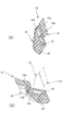
図3は、可動体14とこれを作動させる機構との関係を具体的に示している。図3中(a)は可動体14が第2姿勢にある状態を示し、また図3中(b)は可動体14が第1姿勢にある状態を示している。
(2-3. First blade member, second blade member)
Next, the configuration of the
FIG. 3 specifically shows the relationship between the
各可動体14は2つの部材(羽根状部材)を組み合わせて構成されており、具体的には主可動翼片16と副可動翼片18とが含まれる。これら主可動翼片16および副可動翼片18のうち、遊技者からみて手前側に副可動翼片18が位置し、その後側(盤面に近い方)に主可動翼片16が配置されている。ここで、盤面から正面に対する方向を厚み方向(図3中のX軸方向)として規定すると、これら主可動翼片16と副可動翼片18とは互いに厚み方向に重なり合い、そして、主可動翼片16の前面のうち、その大部分は副可動翼片18により覆われた状態にある。
Each
この状態で、主可動翼片16の先端部分16aは副可動翼片18に覆われておらず、その他の部分よりも厚み方向に大きく成形されている分だけ手前側に張り出している。これを可動体14の回転方向(図3中X軸回り)でみると、先端部分16aは副可動翼片18に対して上側(図3中(a))またはその内側(図3中(b))に重なり合っており、先端部分16aの前面と副可動翼片18の前面とはほぼ同一の平面(図3中Y−Z平面)内に位置するものとなっている。
In this state, the
本実施形態の場合、上記の球受け面14aは主可動翼片16および副可動翼片18の両方から構成されている。例えば図3中(a)に示されているように、主可動翼片16についてはその先端部分16aの上面、また、副可動翼片18については先端部分16aに重ならない部分の上面にそれぞれ球受け面14aが形成される。これを図3中(b)の状態でみると、主可動翼片16の先端部分16aおよび副可動翼片18について、いずれもセンター役物8の内側を向いた面に上記の球受け面14aとなる範囲が規定されることとなる。また以上の説明により、前述した球受け面14aの段付き形状は、主可動翼片16の先端部分16aと副可動翼片18との間に存する段差に起因していることが理解される。
In the case of this embodiment, the above-described
(3.作動機構)
可動体14を作動させる駆動源として、本実施形態では2つのソレノイド26が用いられている。これら2つのソレノイド26を含む作動機構の大部分は遊技盤4の裏面側に配置されており、通常、遊技者からは視認されない。作動機構では、2つのソレノイド26が連結ビーム28を垂直方向に上げ下げし、この上下動作が駆動軸30の回転動作に変換されるものとなっている。なお、このような機能は公知の構造により実現できるため、ここでは詳細な説明を省略する。また、本実施形態では2つのソレノイド26が用いられているが、ソレノイド26は1つまたは3つ以上であってもよい。
(3. Operating mechanism)
In this embodiment, two
上記の主可動翼片16および副可動翼片18のうち、作動機構に直接連結されているのは主可動翼片16である。すなわち、主可動翼片16はその基端部が駆動軸30に接続されており、作動機構により駆動軸30が回転動作されると、その動力によって主可動翼片16が回転動作される。一方、副可動翼片18は駆動軸30とは別の位置で基端部が回転自在に支持されている。
Of the main
(4.リンク機構)
次に図4は、主可動翼片16と副可動翼片18との連結関係を詳細に示している。図4では主可動翼片16および副可動翼片18の縦断面(図3中Y−Z平面に沿う断面)が示されており、それゆえ副可動翼片18の構造についての理解が一層容易となっている。
(4. Link mechanism)
Next, FIG. 4 shows the connection relationship between the main
上記のように、主可動翼片16の基端部には駆動軸30の一端が固定されており、この状態で駆動軸30の一端は主可動翼片16の厚み内に嵌め込まれた状態にある。このため主可動翼片16の手前側に副可動翼片18が重ね合わされていても、駆動軸30が副可動翼片18に干渉することはない。
As described above, one end of the
一方、副可動翼片18の基端部には支持ピン32が取り付けられており、この支持ピン32は副可動翼片18の裏面から厚み方向に突出している。支持ピン32の突出端は、例えばセンター役物8の本体部分(図4には示されていない)に回転自在に支持されており、これにより、副可動翼片18が盤面に沿う方向にて回転動作可能となっている。
On the other hand, a
上記の支持ピン32は駆動軸30よりも上方で、かつ、センター役物8に対してやや内側よりに離れて位置しており、これら支持ピン32と駆動軸30との間には適当なクリアランスが確保されている。また図4中に破線を加えて示しているように、主可動翼片16はその基端部から先端部分16aにかけて僅かに屈曲するようにして成形されており、可動体14としての第1姿勢(図4中(a))にある状態では、主可動翼片16がその屈曲によって抉られた部分の内側にて支持ピン32との干渉を回避することができるものとなっている。
The support pins 32 are positioned above the
主可動翼片16と副可動翼片18とを相互に連結するため、主可動翼片16にはスライドピン16bが取り付けられており、また副可動翼片18にはその長手方向に延びるガイド溝18aが形成されている。スライドピン16bは主可動翼片16から手前側に突出しており、またガイド溝18aは副可動翼片18の裏面側にて開放されている。それゆえ、主可動翼片16の手前側に副可動翼片18が重ね合わせられた状態で、スライドピン16bはガイド溝18a内に嵌り込むことができ、この状態でガイド溝18aに沿ってスライド可能となっている。
In order to connect the main
ガイド溝18aは、支持ピン32の外側位置から副可動翼片18の先端寄りの位置までの間に形成されており、これら主可動翼片16および副可動翼片18がともに可動体14としての第1姿勢(図4中(a))にある状態では、ガイド溝18aのほぼ中間位置にスライドピン16bが位置している。
The
この状態から、作動機構の動力によって可動体14を拡開させる方向(図4では反時計回り方向)に主可動翼片16が回転動作されると、スライドピン16bがガイド溝18aを介して副可動翼片18を回転方向に押すので、これによって副可動翼片18が同じ方向に回転動作される。
From this state, when the main
このような主可動翼片16および副可動翼片18の回転動作の過程で、スライドピン16bは副可動翼片18の先端方向に向けてガイド溝18a内を相対的にスライドしながら移動する。そして、これらがともに可動体14としての第2姿勢(図4中(b))まで変位すると、スライドピン16bはガイド溝18aの終端に到達する。この状態でスライドピン16bはガイド溝18aの終端縁に当接しているため、それ以上のスライドは規制される。これにより、主可動翼片16および副可動翼片18の回転変位が停止されるので、これらがともに可動体14としての第2姿勢を超えてさらに回転動作されることはない。
In the course of the rotation operation of the main
なお、このとき合わせて可動体14の第2姿勢でソレノイド26のプランジャが伸長するストロークも終端に達しており、上記のようにスライドピン16bがガイド溝18aの終端縁に当接した状態で、それ以上の過度な回転動力が駆動軸30から付与されないように設定されていればより好ましい態様となる。
At this time, the stroke of the plunger of the
これとは逆に、可動体14を第2姿勢から第1姿勢に向けて復帰させる方向(図4では時計回り方向)に主可動翼片16が回転動作されると、スライドピン16bはガイド溝18aの終端から離れて逆方向(基端方向)にスライドし始める。このときもスライドピン16bがガイド溝18aを介して副可動翼片18を回転方向に押すので、これによって副可動翼片18が同じ方向に回転動作される。
On the contrary, when the main
この場合も主可動翼片16および副可動翼片18の回転動作の過程で、スライドピン16bはガイド溝18a内を相対的にスライドしながら移動する。そして、これらがともに可動体14としての第1姿勢(図4中(a))まで変位すると、スライドピン16bはガイド溝18aの中間位置でスライドを停止する。このときソレノイド26のプランジャが収縮するストロークが終端に達するため、主可動翼片16および副可動翼片18がともに回転動作を停止することとなる。
Also in this case, the
なお、図4では一方(ここでは左側)の可動体14についてのみ示しているが、他方の可動体14の変位については上記と対称に考えることができる。
In FIG. 4, only one (left side here)
(5.動作例)
次に、上記のリンク機構を介して連結された主可動翼片16および副可動翼片18がともに回転動作される場合の動作例について説明する。
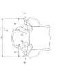
図5は、可動体14の変位と各所の寸法との関係を示している。本実施形態ではその構造上、駆動軸30が支持ピン32よりもセンター役物8の外側寄りに位置しており(水平偏心量Hで表される)、また、駆動軸30が支持ピン32より下方に位置している(垂直偏心量Vで表される)。
(5. Example of operation)
Next, an operation example in the case where both the main
FIG. 5 shows the relationship between the displacement of the
さらに本実施形態ではその構造上、主可動翼片16の回転中心である駆動軸30からその先端までの距離(半径R1で示される)は一定であり、また、副可動翼片18の回転中心である支持ピン32からその先端までの距離(半径R2で示される)もまた一定である。
Further, in this embodiment on its structure, the main distance from the
上記の構造において、主可動翼片16および副可動翼片18がともに可動体14としての第1姿勢にある状態(2点鎖線)と第2姿勢にある状態(実線)とを対比すると、第2姿勢にある状態よりも第1姿勢にある状態の方が主可動翼片16に対して副可動翼片18の重なる範囲が大きく、それだけ両者の先端位置が互いに近接した状態にある。これに対し、第1姿勢にある状態よりも第2姿勢にある状態の方が主可動翼片16に対して副可動翼片18の重なる範囲が小さく、それだけ両者の先端位置が互いに離隔した状態にあるといえる。
In the above structure, when the state in which the main
このため、可動体14が第1姿勢にある状態で球受け面14aとして規定される範囲Cは、可動体14が第2姿勢にある状態で球受け面14aとして規定される範囲C’よりも小さい(C<C’)。これを可動体14が第1姿勢から第2姿勢に向けて変位される過程でみると、主可動翼片16および副可動翼片18がともに回転動作される過程で、可動体14に球受け面14aとして規定される範囲は拡張されている(C→C’)。また、このとき球受け面14aが拡張される方向は可動体14の拡開する方向と逆向き、つまり、センター役物8の内側方向である。
Therefore, the range C defined as the
しかしその一方で、主可動翼片16および副可動翼片18の長さはいずれも不変であり、特にこれら主可動翼片16および副可動翼片18の全長が構造的に伸長されているわけではない。したがって、これらを可動体14全体としてみると、その回転中心(駆動軸30)から球受け面14aの末端までの長さは変わらず一定である。なお、ここで主可動翼片16の回転中心を可動体14の回転中心と規定しているのは、球受け面14aの末端が主可動翼片16の先端部分16aにより規定されているからである。
However, on the other hand, the lengths of the main
次に図6は、左右の可動体14についての動作例を示している。上記の動作例では片側(ここでは左側)の可動体14についてのみ示しているが、センター役物8の作動により左右の可動体14が動作されると、遊技者には以下のように視認される。
Next, FIG. 6 shows an operation example of the left and right
例えば、通常遊技中にセンター役物8が作動されていない場合、遊技者からは左右の可動体14がともに第1姿勢(2点鎖線)にある状態で視認される。この場合、遊技者は可動体14の大きさから球受け面14aの長さを目視によって推し量り、センター役物8が作動したときの入賞確率をおおよそイメージすることができる。なお、このとき遊技者からは、可動体14の球受け面14aとなる部分の長さとして短い方の範囲Cが視認されている。
For example, when the
この状態で、始動入賞等によってセンター役物8が作動すると、各可動体14が第2姿勢(実線)に変位することとなる。この変位の過程で、可動体14は球受け面14aとなる部分の長さが範囲Cから範囲C’に拡張されるため、遊技者からはそれまでイメージしていたよりも入賞しやすくなったかのように視認される。このときの視覚的効果により、センター役物8に入賞しやすい状況になったと遊技者に錯覚させることで、入賞の期待感が一層高まり、興趣性の高い遊技を提供することが可能となる。
In this state, when the
その一方で、本実施形態では可動体14の回転中心からその先端、つまり、球受け面14aの末端までの長さが構造的に伸長されているわけではない。したがって、左右の可動体14が拡開した場合であっても、予め規定された開口幅Wが変動したり拡張されたりすることはなく、その大きさは常に一定であるので、パチンコ機1の射幸性が過度に高くなってしまうことはない。
On the other hand, in this embodiment, the length from the rotation center of the
この点、例えば可動体の先端から突出したり引っ込んだりできる補助部材を備えたタイプの可変入賞装置では、補助部材が引っ込んだままの状態だと開口幅が小さすぎて興趣性に乏しくなってしまうし、逆に補助部材が突出した状態だと開口幅が大きくなりすぎるため、ややもすると射幸性が過度に高くなってしまうおそれがあるが、本実施形態ではそのような問題が生じることはない。 In this respect, for example, in a variable winning device of a type provided with an auxiliary member that can protrude or retract from the tip of the movable body, if the auxiliary member remains in the retracted state, the opening width is too small and the interest is poor. On the other hand, if the auxiliary member is in a protruding state, the opening width becomes too large, and there is a risk that the euphoria may become excessively high. However, in this embodiment, such a problem does not occur.
(6.その他の実施形態についての言及)
以上は一実施形態についての説明であるが、本発明の実施の形態がこれに制約されることはない。以下に、その他の実施形態についていくつか例を挙げて言及する。
(6. Reference to other embodiments)
The above is the description of one embodiment, but the embodiment of the present invention is not limited to this. In the following, other embodiments will be described with some examples.
(1)一実施形態では可変入賞装置としてセンター役物を例に挙げているが、可変入賞装置は電動チューリップ型のものやその他の形態のものであってもよく、可動体の動作によって入賞確率が変化するものであれば特にその形態は限定されない。 (1) In one embodiment, the center prize is taken as an example of the variable winning device. However, the variable winning device may be an electric tulip type or other forms, and the winning probability depends on the operation of the movable body. The form is not particularly limited as long as the value changes.
(2)一実施形態の作動機構では駆動源としてソレノイドを用いているが、その他の駆動源(例えばモータ)を用いてもよい。 (2) In the operation mechanism of one embodiment, a solenoid is used as a drive source, but other drive sources (for example, a motor) may be used.
(3)一実施形態では作動機構の駆動軸が主可動翼片に接続されているが、副可動翼片に駆動軸が接続されている態様であってもよい。この場合、駆動軸から副可動翼片に与えられた動力がリンク機構を介して主可動翼片に伝達され、上記の動作例と同様に機能することができる。 (3) In one embodiment, the drive shaft of the operating mechanism is connected to the main movable blade piece, but the drive shaft may be connected to the sub movable blade piece. In this case, the power given from the drive shaft to the sub movable blade piece is transmitted to the main movable blade piece via the link mechanism, and can function in the same manner as the above operation example.
(4)一実施形態では主可動翼片にスライドピンが設けられており、副可動翼片にガイド溝が形成されている例を挙げているが、これらは互いに逆の配置であってもよい。また、一実施形態で挙げたリンク機構の具体的な構成(スライドピン、ガイド溝)はあくまで好ましい例示であり、同様の機能を果たす機構であればその構成を適宜変更してもよい。 (4) In one embodiment, an example is given in which a slide pin is provided on the main movable wing piece and a guide groove is formed on the sub-movable wing piece. However, these may be arranged opposite to each other. . In addition, the specific configuration (slide pin, guide groove) of the link mechanism described in the embodiment is a preferable example to the last, and the configuration may be appropriately changed as long as it has a similar function.
(5)その他、一実施形態で挙げたセンター役物の構成や各可動翼片の具体的な形状、構造等はいずれも好ましい例示であり、これらは適宜変更可能である。 (5) In addition, the configuration of the center accessory and the specific shape and structure of each movable wing piece listed in one embodiment are all preferable examples, and these can be changed as appropriate.
1 パチンコ機
8 センター役物
14 可動体
14a 球受け面
16 主可動翼片
16b スライドピン
18 副可動翼片
18a ガイド溝
26 ソレノイド
28 連結ビーム
30 駆動軸
32 支持ピン
DESCRIPTION OF SYMBOLS 1
Claims (3)
前記可動体を所定の回転中心回りに回転動作させ、前記入賞口に対して所定の第1姿勢と第2姿勢との間にて変位させる作動機構と
を備え、前記可動体が前記第2姿勢に変位された状態でその上面側となる位置に球受け面が形成され、この球受け面にて遊技球を受け止めて前記入賞口に向けて案内可能である遊技機であって、
前記可動体は、
基端部が第1の駆動軸に支持されて当該第1の駆動軸を支点として回転動作される第1の羽根状部材と、
前記第1の羽根状部材とともに可動体を構成し、かつ、基端部が前記第1の駆動軸と異なる第2の駆動軸を支点として回転動作しうる第2の羽根状部材とを有し、
前記第1の羽根状部材と前記第2の羽根状部材とは、
相互に連結されており、前記第1の羽根状部材が前記第1の駆動軸を支点として回転動作されるのに伴い、当該第1の羽根状部材に連結されている前記第2の羽根状部材が、前記第2の駆動軸を支点として回転動作されるに際して当該第1の羽根状部材に対して長手方向に相対的にスライドするリンク機構により構成されており、
前記可動体としての前記第1および前記第2の羽根状部材がともに前記第2姿勢に変位されたとき、前記第2の駆動軸から前記第2の羽根状部材の先端部までの距離により規定される当該可動体全体の長さが前記第1姿勢と前記第2姿勢とで略同じでありながらも、前記第1の羽根状部材に対して前記第2の羽根状部材が長手方向にスライドすることによって、前記入賞口に入賞しやすくなったと遊技者に錯覚させうる
ことを特徴とする遊技機。 A variable winning device that includes a movable body that is actuated when a predetermined operating condition is established, and that can change a winning probability to a winning opening according to an operating state of the movable body;
An operating mechanism for rotating the movable body around a predetermined rotation center and displacing the winning opening between a predetermined first posture and a second posture with respect to the prize opening, wherein the movable body is in the second posture. A gaming machine in which a ball receiving surface is formed at a position on the upper surface side in a displaced state, and a game ball can be received on the ball receiving surface and guided toward the winning opening,
The movable body is
A first blade-like member whose base end is supported by the first drive shaft and rotated about the first drive shaft;
A second blade-shaped member that constitutes a movable body together with the first blade-shaped member, and whose base end portion can rotate about a second drive shaft that is different from the first drive shaft; ,
The first blade-shaped member and the second blade-shaped member are:
The second blades are connected to each other and are connected to the first blade member as the first blade member is rotated about the first drive shaft. When the member is rotated about the second drive shaft as a fulcrum, the member is constituted by a link mechanism that slides relative to the first blade-like member in the longitudinal direction,
Defined by the distance from the second drive shaft to the tip of the second blade-like member when both the first and second blade-like members as the movable body are displaced to the second posture. The length of the entire movable body is substantially the same between the first posture and the second posture, but the second blade-shaped member slides in the longitudinal direction with respect to the first blade-shaped member. it allows Yu Technical machine you characterized by capable of illusion and the player becomes easier to win the winning hole to be.
請求項1に記載の遊技機。 When the first and second blade-like members as the movable body rotate together until they are displaced to the second posture, the relative relationship of the second blade-like member with respect to the first blade-like member. The gaming machine according to claim 1, wherein the rotation operation of the first blade-shaped member and the second blade-shaped member is stopped by regulating the slide.
請求項1または2に記載の遊技機。 The gaming machine according to claim 1, wherein a pair of the movable bodies are provided on the left and right sides of the winning opening.
Priority Applications (1)
| Application Number | Priority Date | Filing Date | Title |
|---|---|---|---|
| JP2003394322A JP4595109B2 (en) | 2003-11-25 | 2003-11-25 | Game machine |
Applications Claiming Priority (1)
| Application Number | Priority Date | Filing Date | Title |
|---|---|---|---|
| JP2003394322A JP4595109B2 (en) | 2003-11-25 | 2003-11-25 | Game machine |
Publications (3)
| Publication Number | Publication Date |
|---|---|
| JP2005152239A JP2005152239A (en) | 2005-06-16 |
| JP2005152239A5 JP2005152239A5 (en) | 2009-11-05 |
| JP4595109B2 true JP4595109B2 (en) | 2010-12-08 |
Family
ID=34720425
Family Applications (1)
| Application Number | Title | Priority Date | Filing Date |
|---|---|---|---|
| JP2003394322A Expired - Fee Related JP4595109B2 (en) | 2003-11-25 | 2003-11-25 | Game machine |
Country Status (1)
| Country | Link |
|---|---|
| JP (1) | JP4595109B2 (en) |
Families Citing this family (2)
| Publication number | Priority date | Publication date | Assignee | Title |
|---|---|---|---|---|
| JP2008245703A (en) * | 2007-03-29 | 2008-10-16 | Daito Giken:Kk | Game table |
| JP5008187B2 (en) * | 2007-05-28 | 2012-08-22 | ダイコク電機株式会社 | Pachinko gaming machine variable winning device and pachinko gaming machine using the same |
Citations (2)
| Publication number | Priority date | Publication date | Assignee | Title |
|---|---|---|---|---|
| JPS60137376A (en) * | 1983-12-27 | 1985-07-20 | 株式会社ソフイア | Pinball machine |
| JPH07241367A (en) * | 1994-03-04 | 1995-09-19 | Ace Denken:Kk | Variable prize-winning device for pachinko machine |
-
2003
- 2003-11-25 JP JP2003394322A patent/JP4595109B2/en not_active Expired - Fee Related
Patent Citations (2)
| Publication number | Priority date | Publication date | Assignee | Title |
|---|---|---|---|---|
| JPS60137376A (en) * | 1983-12-27 | 1985-07-20 | 株式会社ソフイア | Pinball machine |
| JPH07241367A (en) * | 1994-03-04 | 1995-09-19 | Ace Denken:Kk | Variable prize-winning device for pachinko machine |
Also Published As
| Publication number | Publication date |
|---|---|
| JP2005152239A (en) | 2005-06-16 |
Similar Documents
| Publication | Publication Date | Title |
|---|---|---|
| JP4926194B2 (en) | Game machine | |
| JP2007275235A (en) | Movable presentation device of game machine | |
| JP2011183051A (en) | Pachinko machine | |
| JP5134921B2 (en) | Pachinko machines with a center role | |
| JP4947784B2 (en) | Display device for gaming machine | |
| JP4766250B2 (en) | Game machine | |
| JP4595109B2 (en) | Game machine | |
| JPH1142334A (en) | Pachinko machine | |
| JP4664743B2 (en) | Game machine | |
| JP4560535B2 (en) | Center function of pachinko machine | |
| JP4848340B2 (en) | Pachinko machine | |
| JP4278544B2 (en) | Game machine | |
| JP6157446B2 (en) | Game machine | |
| JP4560536B2 (en) | Center function of pachinko machine | |
| JP5271651B2 (en) | A pachinko machine with an accessory | |
| JP6742271B2 (en) | Amusement machine | |
| JP2002177514A (en) | Winning device for pachinko game machine, or the like | |
| JP4274305B2 (en) | Game machine shelf equipment | |
| JP2009066229A (en) | Center accessory of pachinko game machine | |
| JP3527698B2 (en) | Winning device | |
| JP5400338B2 (en) | A pachinko machine with an accessory | |
| JP4728374B2 (en) | Game machine | |
| JP4863273B2 (en) | GAME BOARD UNIT, GAME MACHINE, AND GAME AREA EXPANSION METHOD | |
| JP4609853B2 (en) | Game machine | |
| JP2016007408A (en) | Game machine |
Legal Events
| Date | Code | Title | Description |
|---|---|---|---|
| A621 | Written request for application examination |
Free format text: JAPANESE INTERMEDIATE CODE: A621 Effective date: 20060531 |
|
| RD04 | Notification of resignation of power of attorney |
Free format text: JAPANESE INTERMEDIATE CODE: A7424 Effective date: 20071221 |
|
| A521 | Written amendment |
Free format text: JAPANESE INTERMEDIATE CODE: A523 Effective date: 20090910 |
|
| A977 | Report on retrieval |
Free format text: JAPANESE INTERMEDIATE CODE: A971007 Effective date: 20091203 |
|
| A131 | Notification of reasons for refusal |
Free format text: JAPANESE INTERMEDIATE CODE: A131 Effective date: 20091208 |
|
| A521 | Written amendment |
Free format text: JAPANESE INTERMEDIATE CODE: A523 Effective date: 20100205 |
|
| RD02 | Notification of acceptance of power of attorney |
Free format text: JAPANESE INTERMEDIATE CODE: A7422 Effective date: 20100205 |
|
| A521 | Written amendment |
Free format text: JAPANESE INTERMEDIATE CODE: A821 Effective date: 20100205 |
|
| A131 | Notification of reasons for refusal |
Free format text: JAPANESE INTERMEDIATE CODE: A131 Effective date: 20100415 |
|
| A521 | Written amendment |
Free format text: JAPANESE INTERMEDIATE CODE: A523 Effective date: 20100610 |
|
| TRDD | Decision of grant or rejection written | ||
| A01 | Written decision to grant a patent or to grant a registration (utility model) |
Free format text: JAPANESE INTERMEDIATE CODE: A01 Effective date: 20100803 |
|
| A01 | Written decision to grant a patent or to grant a registration (utility model) |
Free format text: JAPANESE INTERMEDIATE CODE: A01 |
|
| A61 | First payment of annual fees (during grant procedure) |
Free format text: JAPANESE INTERMEDIATE CODE: A61 Effective date: 20100901 |
|
| R150 | Certificate of patent or registration of utility model |
Ref document number: 4595109 Country of ref document: JP Free format text: JAPANESE INTERMEDIATE CODE: R150 Free format text: JAPANESE INTERMEDIATE CODE: R150 |
|
| FPAY | Renewal fee payment (event date is renewal date of database) |
Free format text: PAYMENT UNTIL: 20131001 Year of fee payment: 3 |
|
| R250 | Receipt of annual fees |
Free format text: JAPANESE INTERMEDIATE CODE: R250 |
|
| R250 | Receipt of annual fees |
Free format text: JAPANESE INTERMEDIATE CODE: R250 |
|
| R250 | Receipt of annual fees |
Free format text: JAPANESE INTERMEDIATE CODE: R250 |
|
| R250 | Receipt of annual fees |
Free format text: JAPANESE INTERMEDIATE CODE: R250 |
|
| R250 | Receipt of annual fees |
Free format text: JAPANESE INTERMEDIATE CODE: R250 |
|
| LAPS | Cancellation because of no payment of annual fees |