JP4594420B2 - Data conversion apparatus and control method thereof - Google Patents
Data conversion apparatus and control method thereof Download PDFInfo
- Publication number
- JP4594420B2 JP4594420B2 JP2008331190A JP2008331190A JP4594420B2 JP 4594420 B2 JP4594420 B2 JP 4594420B2 JP 2008331190 A JP2008331190 A JP 2008331190A JP 2008331190 A JP2008331190 A JP 2008331190A JP 4594420 B2 JP4594420 B2 JP 4594420B2
- Authority
- JP
- Japan
- Prior art keywords
- data
- conversion
- input
- input data
- rounding
- Prior art date
- Legal status (The legal status is an assumption and is not a legal conclusion. Google has not performed a legal analysis and makes no representation as to the accuracy of the status listed.)
- Expired - Fee Related
Links
Images


Classifications
-
- H—ELECTRICITY
- H03—ELECTRONIC CIRCUITRY
- H03M—CODING; DECODING; CODE CONVERSION IN GENERAL
- H03M7/00—Conversion of a code where information is represented by a given sequence or number of digits to a code where the same, similar or subset of information is represented by a different sequence or number of digits
- H03M7/30—Compression; Expansion; Suppression of unnecessary data, e.g. redundancy reduction
-
- G—PHYSICS
- G06—COMPUTING; CALCULATING OR COUNTING
- G06F—ELECTRIC DIGITAL DATA PROCESSING
- G06F17/00—Digital computing or data processing equipment or methods, specially adapted for specific functions
- G06F17/10—Complex mathematical operations
- G06F17/14—Fourier, Walsh or analogous domain transformations, e.g. Laplace, Hilbert, Karhunen-Loeve, transforms
- G06F17/145—Square transforms, e.g. Hadamard, Walsh, Haar, Hough, Slant transforms
-
- H—ELECTRICITY
- H04—ELECTRIC COMMUNICATION TECHNIQUE
- H04N—PICTORIAL COMMUNICATION, e.g. TELEVISION
- H04N19/00—Methods or arrangements for coding, decoding, compressing or decompressing digital video signals
- H04N19/42—Methods or arrangements for coding, decoding, compressing or decompressing digital video signals characterised by implementation details or hardware specially adapted for video compression or decompression, e.g. dedicated software implementation
Description
本発明は、画像データをブロック単位で変換しロスレス符号化とロッシー符号化を統一スキームで処理するために不可欠であるロスレス直交変換において、特に該ロスレス直交変換を構成する各種のロスレス回転変換を実現するための、n次整数データからn次整数データへの可逆変換可能なデータ変換技術に関するものである。 The present invention realizes various lossless rotation transforms that constitute the lossless orthogonal transform, especially in the lossless orthogonal transform, which is indispensable for transforming image data in units of blocks and processing lossless coding and lossy coding with a unified scheme. Therefore, the present invention relates to a data conversion technique capable of reversible conversion from n-order integer data to n-order integer data.
画像、特に多値画像は非常に多くの情報を含んでおり、その画像を蓄積・伝送する際にはデータ量が膨大になってしまうという問題がある。このため画像の蓄積・伝送に際しては、画像の持つ冗長性を除く、或いは画質の劣化が視覚的に認識し難い程度で画像の内容を変更することによってデータ量を削減する高能率符号化が用いられる。 Images, particularly multi-valued images, contain a great deal of information, and there is a problem that the amount of data becomes enormous when storing and transmitting the images. For this reason, when storing and transmitting images, high-efficiency coding is used to reduce the amount of data by removing the redundancy of the images or changing the contents of the images to such an extent that deterioration in image quality is difficult to visually recognize. It is done.
例えば、静止画像の国際標準符号化方式としてISOとITU−Tにより勧告されたJEPG規格では、画像データをブロックごと(8画素×8画素)に離散コサイン変換(DCT)してDCT係数に変換した後に、各係数を各々量子化し、さらにエントロピー符号化することにより画像データを圧縮している。このDCTを利用した圧縮技術にはJPEG以外に、H261,MPEG1/2/4等がある。 For example, in the JEPG standard recommended by ISO and ITU-T as an international standard encoding method for still images, image data is converted into DCT coefficients by discrete cosine transform (DCT) for each block (8 pixels × 8 pixels). Later, each coefficient is quantized and further entropy encoded to compress the image data. In addition to JPEG, there are H261, MPEG1 / 2/4, and the like as compression techniques using DCT.
JPEG規格において、圧縮・伸長後の画像が元の画像と完全に一致するようロスレス符号化も規格化されたが、当時はロスレス変換技術の研究が進んでおらず、DCTを用いてロスレス変換を実現することができなかった。そのため、DCTを用いたブロック変換符号化とは異なる、画素単位の予測符号化という方法でロスレス符号化を実現していた。 In the JPEG standard, lossless coding was also standardized so that the image after compression / decompression completely matches the original image, but at that time, research on lossless conversion technology was not advanced, and lossless conversion was performed using DCT. Could not be realized. Therefore, lossless encoding has been realized by a method called predictive encoding in units of pixels, which is different from block transform encoding using DCT.
その後、ロスレス符号化専用の標準符号化技術(JPEG−LS)が規格化されたが、ロスレス変換を用いた符号化ではなく、更に後に規格化されたJPEG2000において、初めてロスレス・ウェーブレット変換を用いたロスレス変換符号化が可能になった。このロスレス変換は、整数データ群から整数データ群への可逆な変換である。ロスレス変換を用いた符号化は、変換係数を量子化しなければ文字通りロスレス符号化を行なうが可能になる。また、量子化処理を介在させることにより、ロッシー符号化を行なうことができる。すなわち、同一変換スキームでロスレス符号化とロッシー符号化をシームレスに行なうことができるという利点がある。そのため、ロスレス変換を用いた符号化は、現在国際標準化の作業が進行しているJPEG−XRでも用いられている。 After that, standard coding technology dedicated to lossless coding (JPEG-LS) was standardized, but not lossless transformation, but it was used for the first time in JPEG2000, which was later standardized, using lossless wavelet transformation. Lossless transform coding has become possible. This lossless transformation is a reversible transformation from an integer data group to an integer data group. Encoding using lossless transform can literally perform lossless encoding unless the transform coefficient is quantized. In addition, lossy encoding can be performed by interposing a quantization process. That is, there is an advantage that lossless encoding and lossy encoding can be performed seamlessly with the same conversion scheme. Therefore, encoding using lossless transformation is also used in JPEG-XR, which is currently undergoing international standardization work.
ロスレス変換を実現する従来技術の1つとして、ラダー演算(リフティング演算)を用いる方法がある。その代表として非特許文献1が知られている。この非特許文献1では、該ロスレス変換を実現するために、変換行列を三角行列に分解して、それをラダー演算に置き換えるといった複雑な手順で実現している。よって、その構成が複雑になり、演算処理量も多くなってしまう。
As one of the conventional techniques for realizing the lossless transformation, there is a method using a ladder calculation (lifting calculation). Non-patent
また、アダマール変換に限ったロスレス変換手法が、特許文献1に記載されている。この特許文献1に記載の方法は、線形アダマール変換した小数点データの変換係数に対し、奇数個のデータの小数点以下を切り上げ処理し、他の奇数個のデータの小数点以下を切り捨て処理するものである。この特許文献1では、丸め処理の仕方を特徴としており、線形アダマール変換の演算を減らす工夫や丸め処理に要する処理量を減らす工夫などは成されていない。
上記の通り、これまでのロスレス変換技術は、可逆性を実現するために、ラダー演算で冗長な処理を行なう必要があり、ロスレス変換を使ってロスレス符号化やロッシ−符号化を高速に行なうことの妨げとなっていた。 As described above, the conventional lossless transformation technology needs to perform redundant processing by ladder calculation to realize reversibility, and performs lossless coding and lossy coding at high speed using lossless transformation. It was an obstacle.
本願発明は、かかる課題に鑑みなされたものであり、より高速にロスレス変換を行なう技術を提供しようとするものである。 The present invention has been made in view of such a problem, and intends to provide a technique for performing lossless conversion at higher speed.
この課題を解決するため、例えば本発明のデータ変換装置は以下の構成を備える。すなわち、
複数の入力データを入力する入力端子と、複数の変換結果を出力するため出力端子を備えるデータ変換装置であって、
前記入力端子に入力した各入力データに、それぞれに対して設定した第1の重み係数を乗じた結果を取得した後、取得した複数の結果を合算する第1の演算部と、
該第1の演算部から得られる演算結果に、前記入力データ毎に設定した第2の重み係数を乗じた結果を取得した後、それぞれの入力データに加算する第2の演算部と、
前記第1又は第2演算部のうち非整数の重み係数を乗ずる演算部に設けられ、前記非整数の演算結果を整数化する丸め処理部とを備え、
前記第1および第2の重み係数のそれぞれは、前記入力データのそれぞれに対応する前記第1の重み係数と前記第2の重み係数との積を合計した値が0又は−2となるように、設定されることを特徴とする。
In order to solve this problem, for example, the data conversion apparatus of the present invention has the following configuration. That is,
A data conversion device comprising an input terminal for inputting a plurality of input data and an output terminal for outputting a plurality of conversion results,
A first operation unit that obtains a result obtained by multiplying each input data input to the input terminal by a first weighting factor set for each of the input data, and then adds the obtained plurality of results ;
A second operation unit that obtains a result obtained by multiplying the operation result obtained from the first operation unit by a second weighting factor set for each input data, and then adds the result to each input data;
Provided to the arithmetic unit for multiplying the weight coefficient of the non-integer of the previous SL first or second processor, and a rounding unit for rounding the calculation result of the non-integer,
Wherein each of the first and second weighting coefficients, as a value obtained by summing the products of the first weighting factor corresponding to each and said second weighting factor of the input data is 0 or -2 characterized by Rukoto set.
本発明によれば、少ない演算量で低遅延な高速ロスレス変換を実現できる。このロスレス変換を用いることにより、ロスレス・ロッシー符号化を高速に行なえるようになる。特に、同一の記述でソフトウェアとハードウェア処理の両方で、高速なロスレスアダマール変換を実現できる演算を可能にした。これは、ソフトウェアとハードウェア開発の共通化が図れる利点がある。 According to the present invention, high-speed lossless conversion with a small amount of calculation and low delay can be realized. By using this lossless transform, lossless / lossy encoding can be performed at high speed. In particular, operations that can realize high-speed lossless Hadamard transforms with both software and hardware processing with the same description are made possible. This has the advantage that software and hardware development can be shared.
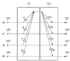
実施形態では、図1に示す構成をベースにしたロスレス変換について説明する。そこで、先ず、図1の構成で実現される変換について詳しく説明する。 In the embodiment, lossless conversion based on the configuration shown in FIG. 1 will be described. First, the conversion realized by the configuration of FIG. 1 will be described in detail.
図1の装置は、第1の演算部111と第2の演算部112で構成される。第1の演算部111は、入力端子101〜104から入力される4つのデータD0,D1,D2,D3それぞれ各々に重み係数a0,a1,a2,a3を乗じ、その重み付きデータを合算(合計を算出)して、その合算結果Eを生成し、出力する。
E=a0*D0+a1*D1+a2*D2+a3*D3
The apparatus of FIG. 1 includes a
E = a0 * D0 + a1 * D1 + a2 * D2 + a3 * D3
第2の演算部112は該合算結果Eに対し、各入力データ毎に設定された第2の重み係数b0,b1,b2,b3を乗じる。第2の演算部112は、それぞれを入力データD0,D1,D2,D3に乗算結果を加算、すなわち、D0+b0*E,D1+b1*E,D2+b2*E,D3+b3*Eを算出し、出力端子121〜124から出力する。
The
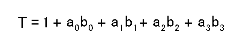
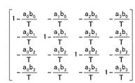
上記の変換の変換行列は図2のように表わすことができる。この行列式は図3、その逆変の換行列は図4のようになる。ロスレス変換符号化では、変換による冗長性の付加や情報の縮退が発生しないようにするため、行列式Tの値は−1または+1である必要がある。
行列式Tの値を−1にするには、a0*b0+a1*b1+a2*b2+a3*b3=−2を満たす必要がある。
行列式Tの値を+1にするには、a0*b0+a1*b1+a2*b2+a3*b3=0を満たす必要がある。
これが第1の演算部111、及び、第2の演算部112の重み係数に課せられる設定条件となる。
The conversion matrix of the above conversion can be expressed as shown in FIG. This determinant is shown in FIG. 3, and the inverse transformation matrix is shown in FIG. In lossless transform coding, the value of the determinant T needs to be −1 or +1 in order to prevent the addition of redundancy or the degeneration of information due to the transform.
In order to set the value of the determinant T to -1, a0 * b0 + a1 * b1 + a2 * b2 + a3 * b3 = −2 must be satisfied.
In order to make the value of the determinant T +1, it is necessary to satisfy a0 * b0 + a1 * b1 + a2 * b2 + a3 * b3 = 0.
This is a setting condition imposed on the weighting coefficients of the
行列式Tの値が−1の時、+1の時の逆変換行列は図5(a)、(b)のようになる。これを見ると、変換行列と逆変換行列との間に興味深い関係があることが分かる。すなわち、行列式Tの値が−1の時、変換行列と逆変換行列が完全に一致している。また、行列式Tの値が+1の時、変換行列における2種類の重み係数の内、どちらか一方の重み係数の符号を反転すると逆変換行列になるという点である。 When the value of the determinant T is -1, the inverse transformation matrix when the value is +1 is as shown in FIGS. From this, it can be seen that there is an interesting relationship between the transformation matrix and the inverse transformation matrix. That is, when the value of the determinant T is −1, the transformation matrix and the inverse transformation matrix completely match. Further, when the value of the determinant T is +1, the inverse transformation matrix is obtained by inverting the sign of one of the two types of weighting coefficients in the transformation matrix.
本発明は、このような変換行列(順変換行列)と逆変換行列の類似性を利用して整数データから整数データへの変換における可逆性を実現する。 The present invention realizes reversibility in conversion from integer data to integer data by utilizing the similarity between such a conversion matrix (forward conversion matrix) and an inverse conversion matrix.
今、行列式Tの値が−1である変換と逆変換を縦属処理して、入力データを変換・逆変換して元の入力データに戻す処理を行なう、図6に示すデータ変換処理に着目する。 Now, in the data conversion process shown in FIG. 6, the conversion and reverse conversion of the determinant T value of −1 are longitudinally processed, and the input data is converted and reverse converted back to the original input data. Pay attention.
このデータ変換処理の結果は、小数データになるのが一般的で、基本的に整数変換にはならない。後述するように、変換側の第1演算部111fの演算結果と、逆変換側の第1演算部111rの演算結果は、絶対値が同じで符号が反転しているといった関係がある。この関係を利用して、このデータ変換装置の可逆性を説明することができる。
The result of this data conversion process is generally decimal data, and is not basically an integer conversion. As will be described later, the calculation result of the first calculation unit 111f on the conversion side and the calculation result of the
変換側の第1演算部111fの演算結果を、第2の演算部112fが前記第2の重み係数を乗じて、各入力データに加算する。逆変換側では、前記演算結果とは符号が反転している演算結果に、同じ第2の重み係数を乗じて、逆変換入力データに加算する。よって、変換側における加算データと逆変換側における加算データが互いに相殺して、入力データだけが残ると言う訳である。
The calculation result of the first calculation unit 111f on the conversion side is multiplied by the second weighting factor by the
変換結果は一般的に小数データになるが、該小数データを整数化した場合にも、上記のように「変換における加算データと逆変換における加算データを互いに相殺」させることが出来れば、可逆性を実現することができる。そのためには、変換側の第1演算部111fの演算結果と、逆変換側の第1演算部111rの演算結果の符号が反転している関係を、もう少し詳しく解析する必要がある。
The conversion result is generally decimal data, but even if the decimal data is converted to an integer, if the added data in the conversion and the added data in the inverse conversion can be canceled as described above, the reversibility Can be realized. For this purpose, it is necessary to analyze the relationship between the calculation result of the first calculation unit 111f on the conversion side and the calculation result of the
図6に示すデータ変換処理において、変換側の第1の演算部111fの出力から逆変換側の第1の演算部111rの出力への伝送係数は前述の「a0*b0+a1*b1+a2*b2+a3*b3=−2」の関係から−2であることが分かる。
In the data conversion process shown in FIG. 6, the transmission coefficient from the output of the first calculation unit 111f on the conversion side to the output of the
これは、変換側における第1演算部111fの演算結果Eが、この伝送係数により−2Eの伝送信号として逆変換側の第1演算部111rの演算結果に含まれることを意味する。該逆変換側の第1演算部111rの演算結果には、前記−2Eの伝送信号以外に、変換側の入力データに対する逆変換側の第1演算部111rの演算結果が含まれ、この分の信号は、変換側の第1演算部111fの演算結果と同様Eになる。
This means that the calculation result E of the first calculation unit 111f on the conversion side is included in the calculation result of the
よって、逆変換処理における第1演算部111rの演算結果は最終的に−2E+E=−Eとなり、変換処理における第1演算部111fの演算結果Eとは符号が反転していることが分かる。
Therefore, it can be seen that the calculation result of the
整数変換における可逆性を保つには、小数点データを整数に変換した後にも上記伝送係数“−2”を保つ必要があり、そのための丸め処理に関する処理方法として次に説明する3つが考えられる。その3つの方法の違いを対比するため、実施形態の説明に入る前に、ここで3つの方法をまとめて説明する。 In order to maintain the reversibility in the integer conversion, it is necessary to maintain the transmission coefficient “−2” even after the decimal point data is converted into an integer, and there are three possible processing methods for rounding for that purpose. In order to contrast the difference between the three methods, the three methods will be described together before the description of the embodiment.
1つ目は、小数点以下のデータが発生する重み係数を全て第1の演算部側に集約し、該第1の演算部の最終段の丸め処理部で、小数点データを整数値に丸めた結果を第1の演算手段の演算結果とする。そして、第2の演算部では該演算結果に整数値に限定された第2の重みを乗じて入力データに加算する演算方法である。丸め処理部を有する第1の演算部の構成として、後述する第1の実施形態を表す図7を参照されたい。 The first result is that all weighting factors that generate data after the decimal point are collected on the first arithmetic unit side, and the rounding unit at the final stage of the first arithmetic unit rounds the decimal point data to an integer value. Is the calculation result of the first calculation means. In the second calculation unit, the calculation result is multiplied by a second weight limited to an integer value and added to the input data. Refer to FIG. 7 showing a first embodiment to be described later as the configuration of the first calculation unit having the rounding processing unit.
このような演算方法で変換と逆変換処理を行なえば、変換側の第1の演算部の出力から逆変換側の第1の演算部における丸め処理部まで、丸め処理を一切しなくて済む。よって、「a0*b0+a1*b1+a2*b2+a3*b3=−2」の条件を満たしていれば、変換側の第1演算部の出力を信号源とする伝送値は正確に−2Eとなって、逆変換側の第1演算部の丸め処理部に到達する。 If conversion and inverse conversion processing are performed by such an arithmetic method, it is not necessary to perform any rounding processing from the output of the first calculation unit on the conversion side to the rounding processing unit in the first calculation unit on the reverse conversion side. Therefore, if the condition “a0 * b0 + a1 * b1 + a2 * b2 + a3 * b3 = −2” is satisfied, the transmission value using the output of the first arithmetic unit on the conversion side as the signal source is accurately −2E, and the reverse The rounding processing unit of the first calculation unit on the conversion side is reached.
この伝送値−2Eは、まぎれもなく整数値であり小数点以下のデータを持たないため、丸め処理の対象にはならず、伝送係数は正確に“−2”となり可逆性が保たれる。 Since this transmission value -2E is undoubtedly an integer value and does not have data after the decimal point, it is not subject to rounding processing, and the transmission coefficient is accurately "-2" and reversibility is maintained.
2つ目は、第2の重み係数が非整数値である場合の丸め処理の方法である。丸め処理部を有する第2の演算部の構成として、後述する第2の実施形態を表す図8を参照されたい。第2の重み係数を乗じて発生する小数点以下の値を切り捨て、その切り捨てた値を別の信号に重畳して伝送する。逆に切り上げた場合には、切り上げた成分を別の信号から差し引いて重畳して伝送する。 The second is a rounding method when the second weighting factor is a non-integer value. Refer to FIG. 8 showing a second embodiment to be described later as the configuration of the second arithmetic unit having the rounding processing unit. A value after the decimal point generated by multiplying the second weighting factor is rounded down, and the rounded down value is superimposed on another signal for transmission. Conversely, when rounded up, the rounded up component is subtracted from another signal and transmitted.
この切り捨て、もしくは、切り上げた成分を別の信号に重畳して伝送する際に、その信号に対する前記第1の重み係数を考慮し、最終的に所望の伝送値となるよう、重畳する値を調整する必要がある。後述する第3の実施形態において、この具体例を述べる。2つ目の方法では、このようにして伝送係数“−2”を正確に実現する。 When this rounded down or rounded up component is superimposed on another signal and transmitted, the first weighting factor for that signal is taken into account, and the value to be superimposed is adjusted so that it finally becomes the desired transmission value There is a need to. This specific example will be described in a third embodiment to be described later. In the second method, the transmission coefficient “−2” is accurately realized in this way.
3つ目も、2つ目と同様、第2の重み係数が非整数値である場合の丸め処理の方法である。2つ目がデータ2つを1組として異なる丸め処理の割り当てを行なったのに対し、それを3つ以上のデータに拡張したのが、この3つ目の処理方法である。この処理は、第1の演算部の演算結果の小数点以下の値が1/nずつ増える毎に、n本の信号の内の1つを+1することにより、1/n単位で信号を伝送する方法である。 The third is also a rounding method when the second weighting factor is a non-integer value, as in the second. The second processing method assigns different rounding processes to two data sets as a set, whereas the third processing method extends the data to three or more data sets. In this process, every time the value after the decimal point of the calculation result of the first calculation unit increases by 1 / n, one of the n signals is incremented by 1, thereby transmitting the signal in units of 1 / n. Is the method.
例えば、第2の重み係数b0,b1,b2の3つが1/3であった場合、重み係数乗算後、1つは単純に小数点以下を切り捨て、もう1つは1/3を加算後に小数点以下を切り捨て、残りの1つは2/3を加算後に小数点以下を切り捨てて整数化を行なう。これによって、3つの信号を通じて1/3、2/3と言う単位を伝達することができる。 For example, if three of the second weighting factors b0, b1, and b2 are 1/3, after multiplying the weighting factors, one simply truncates the decimal point, and the other adds 1/3 and then the decimal point The remaining one is added to 2/3 and then rounded down to the whole number. As a result, units of 1/3 and 2/3 can be transmitted through three signals.
また、第2の重み係数b0とb1の2つが1/2である場合、重み係数乗算後、一方は小数点以下を切り捨て、もう一方は小数点以下を切り上げて整数化すれば、1/2と言う単位を伝達することができる。このように1/nという単位をn個の信号で伝達することによって、伝送係数“−2”を維持する。 Also, if two of the second weighting factors b0 and b1 are ½, after multiplying by the weighting factor, one rounds down the decimal point and the other rounds up the decimal point to make it an integer. Can transmit units. In this way, the transmission coefficient “−2” is maintained by transmitting the unit of 1 / n with n signals.
伝送係数が“−2”になるように丸め処理を調整することは、重み係数の値や近似計算の導入などの状況によって、細かい点で異なるため、すべてを網羅して本明細書に記述することは不可能である。しかし、大枠の考え方は、上で述べた3つの方法に大別できる。 The adjustment of the rounding process so that the transmission coefficient becomes “−2” differs in fine points depending on the situation such as the value of the weighting coefficient and the introduction of approximate calculation. Therefore, all of them are described in this specification. It is impossible. However, the general idea can be broadly divided into the three methods described above.
以下、本発明に係る実施形態を説明する。 Embodiments according to the present invention will be described below.
<第1の実施形態>
本発明の第1の実施形態におけるデータ変換装置(データ変換回路)の構成を図7、図8に示す。どちらの変換も整数化のための丸め処理を無視した場合、その変換行列は図9に示す行列になる。この変換の物理的な意味は、4つの入力データの直流成分を各入力データから減算するというものである。
<First Embodiment>
7 and 8 show the configuration of the data conversion device (data conversion circuit) in the first embodiment of the present invention. In both conversions, when the rounding process for converting to an integer is ignored, the conversion matrix is the matrix shown in FIG. The physical meaning of this conversion is to subtract the DC components of the four input data from each input data.
圧縮符号化の観点からは、あまり意味のない変換ではあるが、本発明の可逆性を説明するのに適した最もシンプルな変換であるため、本発明の一例として採りあげた。 From the viewpoint of compression coding, although this conversion is not very meaningful, it is the simplest conversion suitable for explaining the reversibility of the present invention, and is therefore taken as an example of the present invention.
1つの変換行列に対し、第1の重み係数と第2の重み係数の組み合せが何通りもあり、それに合わせて何種類かの実装形態が存在する。ここでは、代表的な2つの構成を示す。第1の重み係数a0,a1,a2,a3を全て“−1/2”とし、第2の重み係数b0,b1,b2,b3を全て整数値“1”とした時の構成を図7に示す。また、第1の重み係数a0,a1,a2,a3を全て整数値“−1”とし、第2の重み係数b0,b1,b2,b3を全て“1/2”とした時の構成を図8に示す。 There are various combinations of the first weighting factor and the second weighting factor for one transformation matrix, and there are several types of implementations according to the combination. Here, two typical configurations are shown. FIG. 7 shows the configuration when the first weight coefficients a0, a1, a2, and a3 are all “−½” and the second weight coefficients b0, b1, b2, and b3 are all integer values “1”. Show. Also, the configuration when the first weighting factors a0, a1, a2, and a3 are all set to integer values “−1” and the second weighting factors b0, b1, b2, and b3 are all set to “½” is illustrated. It is shown in FIG.
図7の可逆性は、前記3つの方法の1つ目によって説明でき、図8の可逆性は、前記3つの方法の3つ目によって説明することができる。 The reversibility of FIG. 7 can be explained by the first of the three methods, and the reversibility of FIG. 8 can be explained by the third of the three methods.
図7、図8の各々において、4つの入力データを上から順に、第1、第2、第3、第4入力データと呼び、各々の演算途中のデータを、第1、第2、第3、第4データと呼ぶことにする。他の実施形態の説明においても同じ呼び方を用いる。 In each of FIGS. 7 and 8, the four input data are referred to as first, second, third, and fourth input data in order from the top, and the data in the middle of each calculation are referred to as the first, second, and third data. This is called fourth data. The same terminology is used in the description of other embodiments.
整数化する処理が無ければ、この2つの変換は全く同じであるが、整数化の対象となる信号が異なるため、変換結果が微妙に異なる。 If there is no processing for converting to an integer, the two conversions are exactly the same, but the conversion results are slightly different because the signals to be converted into integers are different.
図7の構成では、F=a0*D0+a1*D1+a2*D2+a3*D3=(−D0−D1−D2−D3)/2 を計算するわけであるから、その計算結果Fに小数点以下1ビットのデータが発生することがある。このため、これを整数化丸め処理部113で整数化したround(F)が、第1演算部111の出力Eとなる。整数化の方法は、逆変換器の整数化と共通であれば、切り捨て・切り上げのどちらでもよい。
In the configuration of FIG. 7, F = a0 * D0 + a1 * D1 + a2 * D2 + a3 * D3 = (− D0−D1−D2−D3) / 2 is calculated. May occur. For this reason, round (F) obtained by converting this into an integer by the integer rounding
該整数化した結果、すなわち、第1の演算部111による演算結果Eは、第2の重み係数b0,b1,b2,b3をとおして4つの各入力に重畳され、変換結果として、Di’=Di+E(i=0,1,2,3)を出力する。
The integerized result, that is, the calculation result E by the
該変換結果を逆変換するために、変換処理とまったく同じ処理を行なうと、次のようになる。
round(a0*D0’+a1*D1’+a2*D2’+a3*D3’)
=round((−D0−D1−D2−D3−4E)/2)
=round((−D0−D1−D2−D3)/2−2E)
=round((−D0−D1−D2−D3)/2)−2E
=round(F)−2E
=E−2E
=−E
When the same process as the conversion process is performed in order to reversely convert the conversion result, the result is as follows.
round (a0 * D0 '+ a1 * D1' + a2 * D2 '+ a3 * D3')
= Round ((-D0-D1-D2-D3-4E) / 2)
= Round ((-D0-D1-D2-D3) / 2-2E)
= Round ((-D0-D1-D2-D3) / 2) -2E
= Round (F) -2E
= E-2E
= -E
この構成では、変換器の第1演算部111の出力から逆変換器の第2演算部の出力への伝送係数は、1×4×(−1/2)=−2 になるため、逆変換器の第1演算部の出力は上記のように、−Eになる。
In this configuration, since the transmission coefficient from the output of the
逆変換器はこの“−E”に第2の重み係数“1”を乗じた値−Eを、該逆変換器の各入力データD0’,D1’,D2’,D3’へ加算することにより、元のデータD0,D1,D2,D3を復元することができる。 The inverse converter adds a value -E obtained by multiplying "-E" by the second weighting factor "1" to each input data D0 ', D1', D2 ', D3' of the inverse converter. The original data D0, D1, D2, and D3 can be restored.
次に、第1の重み係数a0,a1,a2,a3が“−1”、第2の重み係数b0,b1,b2,b3が“1/2”である図8の変換内容について簡単に説明する。 Next, the conversion contents of FIG. 8 in which the first weighting factors a0, a1, a2, and a3 are “−1” and the second weighting factors b0, b1, b2, and b3 are “½” will be briefly described. To do.
図8の構成では、第2の演算部112で第2の重み係数“1/2”を乗ずるため、該第2の演算手段において、第2の重み係数を掛けたデータ毎に丸め処理を行なう必要がある。この丸め処理部が4つ存在することが図8の大きな特徴である。
In the configuration of FIG. 8, the
4つの丸め処理の仕方によって、可逆性を保てたり、保てなかったりすることがある。可逆性を保つには、伝送係数が“−2”である図7の構成と等価な処理を行なうか、或いは、伝送係数が正確に“−2”になるようにする必要がある。 Depending on the four rounding methods, reversibility may or may not be maintained. In order to maintain reversibility, it is necessary to perform processing equivalent to the configuration of FIG. 7 in which the transmission coefficient is “−2”, or to make the transmission coefficient exactly “−2”.
図7の構成と等価な処理とは、4つの丸め処理が全部同じ丸め処理を行なう場合である。すなわち、4つとも一律に切り上げ、もしくは、切り捨て処理を行なう。これは、図7における第1の演算部111の丸め処理を、等価な変形によって第2の演算部112に移動した場合の構成条件でもある。
The process equivalent to the configuration of FIG. 7 is a case where all four rounding processes perform the same rounding process. That is, all four are rounded up or rounded down. This is also a configuration condition when the rounding process of the
可逆性を保つもう1つの方法は、伝送係数が正確に“−2”になるようにすることであり、これは、4つの丸め処理の内、半分の2つを切り捨て、残りの半分の2つを切り上げることによって実現できる。 Another way to maintain reversibility is to ensure that the transmission coefficient is exactly “−2”, which means that half of the four rounding operations are rounded down and the remaining half is 2 This can be achieved by rounding up one.
重み係数“1/2”を乗ずることによって、小数点以下のデータが1ビット発生する可能性がある。該小数点以下のデータを丸め処理によって、正確に伝送できなくなると伝送係数が“−2”でなくなってしまう。だが、この小数点以下1ビットの値を、複数の信号を通してうまく伝送できれば、トータルの伝送係数を“−2”にすることが出来る。 By multiplying the weight coefficient “1/2”, there is a possibility that 1 bit of data after the decimal point is generated. If the data after the decimal point cannot be accurately transmitted by the rounding process, the transmission coefficient is not “−2”. However, if this 1-bit value after the decimal point can be successfully transmitted through a plurality of signals, the total transmission coefficient can be set to “−2”.
そのためには、2つの信号を1組として一方の丸め処理を切り捨て、もう一方の丸め処理を切り上げる。このように、2つの信号各々で0.5を伝送する代わりに、2つの信号の一方でまとめて1を伝送する。これにより、見かけ上、小数点以下1ビットの値をうまく伝送できる。 For this purpose, one rounding process is cut off as a set of two signals, and the other rounding process is rounded up. Thus, instead of transmitting 0.5 for each of the two signals, one of the two signals is transmitted together. This makes it possible to successfully transmit a value of 1 bit after the decimal point.
上記内容をまとめると、図8の構成において、可逆性のある変換を実現するには、4つの丸め処理の内、偶数個を切り上げ、残りの偶数個を切り捨て処理すればよいと言える。これは、4つの丸め処理の全組み合せ16通りの内の半分の8通りで可逆性のある変換を行なうことができるということである。 In summary, in order to realize reversible conversion in the configuration of FIG. 8, it can be said that it is only necessary to round up the even number of the four rounding processes and round down the remaining even number. This means that reversible conversion can be performed in 8 of the 16 combinations of the four rounding processes.
このように比較的単純な変換であっても、可逆性変換が可能な丸め処理のバリエーションが多くあるため、複雑な変換になると、可逆変換可能な丸め処理も複雑になる。その場合でも、基本は、伝送係数を“−2”にすることと、それと等価な処理に変形することである。それによって可逆性を保つことが出来る。 Since there are many variations of the rounding process capable of reversible conversion even with such a relatively simple conversion, the rounding process capable of reversible conversion becomes complicated when the conversion is complicated. Even in that case, the basic is to change the transmission coefficient to “−2” and to a process equivalent to it. Thereby, reversibility can be maintained.
図6、図7及び以上の説明から分かるように、本発明の可逆変換を施した変換データから元のデータを復元するための逆変換は、基本的に変換処理と同じである。 As can be seen from FIGS. 6 and 7 and the above description, the inverse transformation for restoring the original data from the transformed data subjected to the reversible transformation of the present invention is basically the same as the transformation process.
特に、丸め処理が第1の演算部にある場合は、丸め処理を含めて完全に変換と逆変換処理は同じである。たとえ丸め処理が第2の演算部にあっても、前記第1の演算部における丸め処理で置き換えが可能な場合には、該第2の演算部における丸め処理も含めて、変換と同じ処理で逆変換することが出来る。 In particular, when the rounding process is in the first arithmetic unit, the conversion and the inverse conversion process are completely the same including the rounding process. Even if the rounding process is in the second arithmetic unit, if it can be replaced by the rounding process in the first arithmetic unit, the same process as the conversion including the rounding process in the second arithmetic unit is performed. Inverse conversion can be performed.
前記以外で、丸め処理が第2の演算部にある場合には、従来のリフティング演算の逆変換と同じ考え方で丸め処理を行なう。すなわち、変換時のリフティング演算で加算した値と全く同じ値を、逆変換時にも生成し、それを減算することによって元のデータに戻す。 Other than the above, when the rounding process is in the second computing unit, the rounding process is performed in the same way as the inverse transformation of the conventional lifting computation. That is, the same value as the value added by the lifting operation at the time of conversion is generated at the time of reverse conversion, and the original data is restored by subtracting it.
まず、逆変換における第1の演算部の出力(−E)を−1倍して、変換時の第1の演算部の出力Eと同じ値にする。それに第2の重み係数を乗じた後に、変換時の第2の演算部の丸め処理と全く同じ処理を、該逆変換の第2の演算部の丸め処理に適用して、変換時と全く同じ値を生成し、該生成結果を減算する。 First, the output (−E) of the first calculation unit in the inverse conversion is multiplied by −1 to obtain the same value as the output E of the first calculation unit at the time of conversion. After multiplying it by the second weighting factor, the same process as the rounding process of the second arithmetic unit at the time of conversion is applied to the rounding process of the second arithmetic unit at the time of the conversion, and exactly the same as at the time of conversion. A value is generated and the generation result is subtracted.
図10(a)、(b)に、図7、図8の構成例における具体的な変換データの例を示すので、その可逆性に着目されたい。 FIGS. 10A and 10B show examples of specific conversion data in the configuration examples of FIGS. 7 and 8, and attention should be paid to the reversibility thereof.
<第1の実施形態の応用例>
前記第1の実施形態の応用例の装置の構成を図11に示す。
<Application example of the first embodiment>
FIG. 11 shows the configuration of an apparatus of an application example of the first embodiment.
本応用例は、前記第1の実施形態の構成をそのまま利用し、該構成の前後に僅かな処理を付加することによって、圧縮符号化で最も基本的な変換の1つであるアダマール変換の可逆変換を実現するものである。 This application example uses the configuration of the first embodiment as it is, and adds a small amount of processing before and after the configuration, thereby reversing Hadamard transform, which is one of the most basic transforms in compression coding. Conversion is realized.
図11は、前記図7に対して、第1の入力データの符号を反転するための第1の符号反転器を設け、該入力データの変換データを出力する際にもう一度符号を反転するために第2の符号反転器を設けたものである。このような構成で変換することによって、4次のロスレスアダマール変換を行なうことが出来る。 FIG. 11 is provided with a first sign inverter for inverting the sign of the first input data with respect to FIG. 7 so as to invert the sign again when the converted data of the input data is output. A second sign inverter is provided. By converting with such a configuration, fourth-order lossless Hadamard transform can be performed.
第1の符号反転器と第2の符号反転器の働きを行列で表すと、各々、単位行列の第1行第1列要素を符号反転して−1にした行列になる。第1の符号反転器は入力データに、第2の符号反転器は変換出力に作用するため、前記符号反転用の行列を図9に示す変換行列の左右から乗じた結果は、図12に示すように4次アダマール変換行列になる。これが、図11に示す構成で実現される変換である。 When the functions of the first code inverter and the second code inverter are represented by a matrix, the first row and first column elements of the unit matrix are each inverted into a matrix of -1. Since the first sign inverter operates on the input data and the second sign inverter operates on the conversion output, the result of multiplying the matrix for sign inversion from the left and right of the conversion matrix shown in FIG. 9 is shown in FIG. Thus, a fourth-order Hadamard transformation matrix is obtained. This is the conversion realized by the configuration shown in FIG.
図8に示す変換器の前後に同じように第1、第2の符号反転器を設けた構成でも、ロスレスアダマール変換が可能であることは説明するまでもない。 Needless to say, lossless Hadamard transform is possible even in the configuration in which the first and second sign inverters are provided before and after the converter shown in FIG.
<第2の実施形態>
本発明の第2の実施形態のデータ変換装置の構成を図13に示す。該変換の変換行列は前記応用例と同じ図12に示す式の右辺の行列と同じである。本第2の実施形態は、前記応用例において、入力段と出力段に設けた2つの符号反転器を第1の演算部301と第2の演算部302で各々吸収し統合したものである。
<Second Embodiment>
FIG. 13 shows the configuration of the data conversion apparatus according to the second embodiment of the present invention. The transformation matrix of the transformation is the same as the matrix on the right side of the equation shown in FIG. In the second embodiment, in the application example, two sign inverters provided in the input stage and the output stage are absorbed and integrated by the first
よって、第1の重み係数a0,a1,a2,a3は各々 1/2,-1/2,-1/2,-1/2であり、第2の重み係数b0,b1,b2,b3は各々 −1,1,1,1である。この時、a0*b0+a1*b1+a2*b2+a3*b3=−2であることは言うまでもない。 Therefore, the first weighting factors a0, a1, a2, and a3 are 1/2, -1/2, -1/2, and -1/2, respectively, and the second weighting factors b0, b1, b2, and b3 are Each is -1,1,1,1. At this time, it goes without saying that a0 * b0 + a1 * b1 + a2 * b2 + a3 * b3 = −2.
図11の構成上で見ると、第1の入力データに対する第1の重み係数と第2の重み係数の符号が各々反転し、重み係数が掛からないデータパス115には符号反転器が入ってくる。しかし、入力側からの符号反転器と出力側からの符号反転器が相殺して、該データパス上の符号反転器は結局無くなり、図13に示す構成となる。
Looking at the configuration of FIG. 11, the signs of the first weighting factor and the second weighting factor for the first input data are inverted, and a sign inverter enters the
本第2の実施形態の第1の演算部における丸め処理を「切り捨て」とした場合、該第1の演算部の演算結果Eは以下のようになる。
E=round((D0−D1−D2−D3)/2)
=(D0−D1−D2−D3)>>1
この演算結果Eを用いて、変換出力は以下のように計算される。
D0’=D0−E
D1’=D1+E
D2’=D2+E
D3’=D3+E
When the rounding process in the first calculation unit of the second embodiment is “rounded down”, the calculation result E of the first calculation unit is as follows.
E = round ((D0−D1−D2−D3) / 2)
= (D0-D1-D2-D3) >> 1
Using this calculation result E, the conversion output is calculated as follows.
D0 '= D0-E
D1 '= D1 + E
D2 '= D2 + E
D3 '= D3 + E
ロスレスアダマール変換には様々な計算方法があるが、上記計算方法はソフトウェアやハードウェアによる制御の元、いずれでも高速に演算でき、本発明の特徴が最も生かされている。 The lossless Hadamard transform has various calculation methods. The above calculation method can be operated at high speed under the control of software or hardware, and the features of the present invention are most utilized.
これまで、ロスレスアダマール変換のソフトウェア、ハードウェアの高速演算法は、どちらか一方のみを高速に演算できるだけであったが、本発明に基づく上記計算方法は両方の処理で高速演算可能である。そのため、ソフト処理とハード処理で同じ計算方法を用いることができる。 Up to now, only one of the high-speed calculation methods of the software and hardware of the lossless Hadamard transform has been able to perform high-speed calculation. However, the calculation method based on the present invention can perform high-speed calculation in both processes. Therefore, the same calculation method can be used for soft processing and hardware processing.
さらに、整数化のための丸め処理を行なわない場合、実数演算の4次アダマール変換となるが、該実数アダマール変換も高速に演算が可能である。 Further, when rounding processing for integer conversion is not performed, the fourth-order Hadamard transform of real number calculation is performed, but the real number Hadamard transform can also be calculated at high speed.
先に示した第1実施形態における図8の構成をベースに、上述の符号反転を行なった場合、第1の重み係数a0,a1,a2,a3は各々1,−1,−1,−1であり、第2の重み係数b0,b1,b2,b3は各々 -1/2,1/2,1/2,1/2である。そして、図8と同様に丸め処理は第2の演算部にて行なうことになる。この場合の構成は図14に示す通りとなる。 When the above-described sign inversion is performed based on the configuration of FIG. 8 in the first embodiment described above, the first weight coefficients a0, a1, a2, and a3 are 1, -1, -1, and -1, respectively. And the second weighting factors b0, b1, b2, and b3 are -1/2, 1/2, 1/2, and 1/2, respectively. Then, as in FIG. 8, the rounding process is performed by the second arithmetic unit. The configuration in this case is as shown in FIG.
図13の構成における第1演算部の丸め処理を「切り捨て」とした場合、該丸め処理と等価な、図14の第2演算部の丸め処理は、第1データのみが「切り上げ」、第2〜4データは「切り捨て」となる。 When the rounding process of the first arithmetic unit in the configuration of FIG. 13 is “rounded down”, the rounding process of the second arithmetic unit in FIG. 14 equivalent to the rounding process is “rounded up” only for the first data. ~ 4 data will be "truncated".
これは、図12の構成において、第1演算部の丸め処理結果を第1データ系列のみ符号反転しているからである。 This is because, in the configuration of FIG. 12, the sign of the rounding process result of the first arithmetic unit is inverted only for the first data series.
同様に、第1演算部の丸め処理を「切り上げ」とした場合、該丸め処理と等価な、図14の第2演算部の丸め処理は、第1データのみが「切り捨て」、第2〜4データは「切り上げ」となる。これらの丸め処理で変換したデータを、逆変換する場合の丸め処理は、変換時と同じでよい。 Similarly, when the rounding process of the first arithmetic unit is “rounded up”, the rounding process of the second arithmetic unit in FIG. 14 equivalent to the rounding process is “rounded down” only for the first data, The data is “rounded up”. The rounding process in the case of inversely converting the data converted by these rounding processes may be the same as that at the time of conversion.
一方、図13とは等価ではない、可逆変換可能な丸め処理は、前記第1の実施形態と同様、多くの種類が存在する。 On the other hand, there are many types of rounding processing that is not equivalent to FIG. 13 and that can be reversibly converted, as in the first embodiment.
第1データとペアになるデータは第1データと同じ丸め処理を行ない、残りの2つのデータは互いに反対の丸め処理を行なうことによって、前記伝送係数を“−2”にすることができ、この条件の丸め処理は6種類ある。そして、この場合の丸め処理に対する逆変換は、第1の実施形態と同様、以下のように行う。 The data paired with the first data is subjected to the same rounding process as the first data, and the remaining two data are subjected to the opposite rounding process, whereby the transmission coefficient can be set to “−2”. There are six types of condition rounding. And the inverse transformation with respect to the rounding process in this case is performed as follows similarly to the first embodiment.
逆変換における第1の演算部の出力(−E)を−1倍して、変換時の第1の演算部の出力Eと符号を合わせて同じ値にする。それに第2の重み係数を乗じた後に、変換時の第2の演算部の丸め処理と同じ処理を適用して、変換時と同じ値を再現する。変換時はこの値を入力データに加算してデータ変換しているので、逆変換で同じ値を減算してやれば、元の入力データを復元することができる。 The output (-E) of the first calculation unit in the reverse conversion is multiplied by -1 to make the same value as the output E of the first calculation unit at the time of conversion. After multiplying it by the second weighting factor, the same processing as the rounding processing of the second arithmetic unit at the time of conversion is applied to reproduce the same value as at the time of conversion. At the time of conversion, this value is added to the input data for data conversion. Therefore, if the same value is subtracted by inverse conversion, the original input data can be restored.
<第3の実施形態>
本発明の第3の実施形態のデータ変換装置の構成を図15と図16に示す。
<Third Embodiment>
The configuration of the data conversion apparatus according to the third embodiment of the present invention is shown in FIGS.
図15と図16に示す構成は、重み付きの入力データに対して4次ロスレスアダマール変換が可能である。 The configurations shown in FIGS. 15 and 16 can perform the fourth-order lossless Hadamard transform on the weighted input data.
本第3の実施形態の説明に入る前に、まず、重み付きデータに関して、簡単に説明する。 Before entering the description of the third embodiment, first, the weighted data will be briefly described.
重み付きのデータは、様々な状況で発生するが、例えば本発明に関連する画像符号化におけるロスレス変換の分野では、少ないリフティング演算でロスレス回転変換を行なおうとすると、その結果、重み付きの変換データが生成される。 Weighted data occurs in various situations. For example, in the field of lossless transformation in image coding related to the present invention, if lossless rotation transformation is performed with a small number of lifting operations, weighted transformation results. Data is generated.
一番簡単な例として、45度回転を2段のリフティング演算で実現する構成を図18に示す。重みの無いのデータに回転変換する正規変換をリフティング演算で実現するには、3段のリフティング演算が必要であることが知られている。これを2段のリフティング演算で行なうと、重み付きのデータへ変換されてしまう。 As the simplest example, FIG. 18 shows a configuration for realizing 45-degree rotation by two-stage lifting calculation. It is known that a three-stage lifting operation is required to realize a normal conversion that rotationally converts data without weight by a lifting operation. If this is performed by a two-stage lifting operation, it is converted to weighted data.
図18の変換によって、生じる重みは(COS45°,1/COS45°)、すなわち、(1/√2,√2)である。端子402から入力するデータYiに、端子401から入力するデータXiを加算して出力するデータYoは、レンジが大きくなり、(√2)の重み付きのデータになる。該データYoを1/2倍して、下側のデータから減算して得られるデータXoは逆にレンジが小さくなり、(1/√2)の重み付きのデータになる。 The weight generated by the conversion of FIG. 18 is (COS45 °, 1 / COS45 °), that is, (1 / √2, √2). The data Yo that is output by adding the data Xi input from the terminal 401 to the data Yi input from the terminal 402 has a larger range and becomes weighted data of (√2). The data Xo obtained by multiplying the data Yo by 1/2 and subtracting from the lower data is conversely reduced in range and becomes weighted data of (1 / √2).
従って、仮に(10、0)の入力データを45°左方向へ回転した場合、本来は(5√2、5√2)に変換されるべきである。しかし、図18の構成では最初のリフティング演算で(10,0+10)に変換され、2段目のリフティング演算で(10−10/2、10)=(5,10)に変換されてしまい、前記重み付きのデータになってしまう。 Therefore, if the input data of (10, 0) is rotated 45 ° leftward, it should be converted into (5√2, 5√2). However, in the configuration of FIG. 18, it is converted to (10, 0 + 10) by the first lifting operation, and is converted to (10-10 / 2, 10) = (5, 10) by the second lifting operation. It becomes weighted data.
このような重み付きの変換を重ねていくと、“2”や“1/2”といった重みが付くことは容易に想像できる。 It can be easily imagined that weights such as “2” and “1/2” are added when such weighted conversions are repeated.
そこで、本第3の実施形態では、第1〜第4入力データに対し(1,2,1/2,1)という重みが付いたデータに、4次ロスレスアダマール変換を行なうことが可能な構成を2例示す。 Therefore, in the third embodiment, a configuration capable of performing a fourth-order lossless Hadamard transform on data with a weight of (1, 2, 1/2, 1) for the first to fourth input data. Two examples are shown.
図15に示す構成は、第1の重み係数a0,a1,a2,a3が各々 -1/4,1/8,1/2,1/4であり、第2の重み係数b0,b1,b2,b3が各々 2,-4,-1,-2である。 In the configuration shown in FIG. 15, the first weighting coefficients a0, a1, a2, and a3 are −1/4, 1/8, 1/2, and 1/4, respectively, and the second weighting coefficients b0, b1, and b2 , B3 are 2, -4, -1, and -2, respectively.
図16に示す構成は、第1の重み係数a0,a1,a2,a3が各々 -1/2,1/4,1,1/2であり、第2の重み係数b0,b1,b2,b3が各々 1,-2,-1/2,-1である。 In the configuration shown in FIG. 16, the first weighting factors a0, a1, a2, and a3 are -1/2, 1/4, 1,1 / 2, respectively, and the second weighting factors b0, b1, b2, and b3 Are 1, -2, -1/2, and -1, respectively.
どちらも、a0*b0+a1*b1+a2*b2+a3*b3=−2 という条件を満たしている。 Both satisfy the condition a0 * b0 + a1 * b1 + a2 * b2 + a3 * b3 = −2.
図15の構成は、第2の重み係数が全て整数なので、第1の演算部301で丸め処理部を持ち整数化した値を出力すれば、第2の演算部302で丸め処理を行なう必要が無い(丸め処理部を持たなくてよい)。この構成は、これまでに説明した実施形態に何度も出てきた構成であり、それらと全く同じ原理でロスレス変換が可能である。
In the configuration of FIG. 15, since the second weighting coefficients are all integers, if the first
但し、図15の構成は、一度整数化したデータを第2の演算部302で2倍、4倍して用いているため、整数化によってデータに重畳した歪も2倍、4倍されるため、整数化による歪が大きくなってしまう。
However, in the configuration of FIG. 15, since the data once converted to an integer is used by being doubled or quadrupled by the second
上記整数化による歪を小さく抑えたのが、図16に示す構成である。第1の演算部311で整数化したデータを、第2の演算部312で2倍にして用いる処理があるが、その箇所は1箇所のみである。
The configuration shown in FIG. 16 suppresses distortion caused by the integerization. There is a process of using the data that has been converted to an integer by the
第2の演算部312における第2の重み係数の中に、絶対値が1より小さい重み(-1/2)が1つだけ存在し、その係数を乗じた結果を整数化するための丸め処理部が必要になる。よって、図16に示す構成では、第1の演算部311と第2の演算部312の両方に丸め処理部を有する。
In the second weighting coefficient in the second
第2の演算部312に存在する丸め処理部の数が1つだけであるため、これまでに説明した実施形態へ適用した手法では、前述の伝送係数を“−2”にすることができず、可逆変換を実現することができない。本実施形態では、前記3つの丸め処理方法の中の2つ目の方法を適用する。
Since the number of the rounding processing units existing in the second
図16に示す構成で、伝送係数を“−2”にするために、前記第2の演算部の丸め処理部で切り捨てた小数点以下の値を、別のデータに重畳する。もしくは、前記丸め処理部で切り上げた小数点以下の値を、別のデータから減算する必要がある。以下の説明を簡略化するため、前記丸め処理では、小数点以下の値(1/2または0)を切り捨てたものとする。 In the configuration shown in FIG. 16, in order to set the transmission coefficient to “−2”, the value after the decimal point rounded down by the rounding unit of the second arithmetic unit is superimposed on another data. Alternatively, it is necessary to subtract the value after the decimal point rounded up by the rounding processing unit from other data. In order to simplify the following description, it is assumed that a value (1/2 or 0) after the decimal point is rounded down in the rounding process.
別のデータに重畳する値は整数値という制限があり、該整数値に1/2 という意味を持たせるには、切り捨てた方のデータと重畳した方のデータとの間で、復号時の第1の重み係数の比が2:1である必要がある。 The value to be superimposed on the other data is limited to an integer value, and in order to make the integer value have the meaning of 1/2, the first value at the time of decoding is between the truncated data and the superimposed data. The ratio of the weighting factors of 1 needs to be 2: 1.
図16の構成では、第2の演算部の丸め処理で切り捨てを行なう第3のデータに対し、第4のデータが上記関係を満足している。よって、図16には示していないが、切り捨てた小数点以下の値を2倍して整数にし、それを第4のデータに加算する。 In the configuration of FIG. 16, the fourth data satisfies the above relationship with respect to the third data that is rounded down by the rounding process of the second arithmetic unit. Therefore, although not shown in FIG. 16, the value after the rounded down decimal is doubled to be an integer and added to the fourth data.
以上の処理によって、前記伝送係数を“−2”にすることができ、可逆変換が可能になる。最後に、本第3の実施形態におけるデータ変換の例を図17に示す。 By the above processing, the transmission coefficient can be set to “−2”, and reversible conversion is possible. Finally, FIG. 17 shows an example of data conversion in the third embodiment.
<第4の実施形態>
本発明の第4の実施形態のデータ変換装置の構成を図19に示す。これまでの実施形態では、4入力データに対する4次変換のみを説明してきたが、本発明は4次変換以外にも適用できる。本実施形態では3次の直交変換の例を示す。
<Fourth Embodiment>
FIG. 19 shows the configuration of the data conversion apparatus according to the fourth embodiment of the present invention. In the embodiments so far, only the fourth-order transformation for four-input data has been described, but the present invention can be applied to other than the fourth-order transformation. In this embodiment, an example of third-order orthogonal transform is shown.
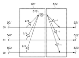
図19に示す構成は、第1演算部511における第1の重み係数a0,a1,a2は全て 2/3であり、第2演算部512における第2の重み係数b0,b1,b2は全て−1である。この重み係数は a0*b0+a1*b1+a2*b2=−2、すなわち、伝送係数は“−2”である。該重み係数によって実現される変換は、図20に示す変換行列で表すことができる。この変換行列は、各行が直交しており、行毎に要素の二乗和が1であるため、正規直交変換であることが分かる。
In the configuration shown in FIG. 19, the first weight coefficients a0, a1, a2 in the
第2の重み係数b0,b1,b2が全て整数であるため、丸め処理は第1の演算部511だけで行なうことができ、3による除算が可能な場合は伝送係数を“−2”にすることは容易である。PC上のソフトウェア処理等では、このような除算が可能である。
Since the second weight coefficients b0, b1, and b2 are all integers, the rounding process can be performed only by the first
一方、高速処理が要求されるハードウェア処理では、3で割る除算を行なうためにわざわざ除算器で演算することはほとんど無く、乗算で近似計算をすることが多い。この場合、2/3ではなく、その近似値を乗算する。例えば2/3を小数点以下12ビットまでの値で近似すると1365/2048となり、この値を乗算する。 On the other hand, in hardware processing that requires high-speed processing, in order to perform division by 3, almost no computation is performed by a divider, and approximate calculation is often performed by multiplication. In this case, the approximate value is multiplied instead of 2/3. For example, when 2/3 is approximated by a value up to 12 bits after the decimal point, 1365/2048 is obtained, and this value is multiplied.
一般的には、近似計算を行なうと、3で割り切れる値に対しても、計算誤差が生じ小数点以下のデータが発生する。該近似計算による計算誤差は変換側の第2の重み係数を通して変換出力データに重畳され、逆変換における第1の演算部511の出力に伝搬する。
In general, when an approximate calculation is performed, a calculation error occurs even for a value divisible by 3, and data below the decimal point is generated. The calculation error due to the approximate calculation is superimposed on the conversion output data through the second weighting coefficient on the conversion side, and propagates to the output of the
逆変換における第1演算部の丸め処理は、本来は、元の入力データ成分だけを第1の重み係数を乗じ合算した結果に対してのみ、効くものであるが、前記近似計算による計算誤差が加わるため、丸め処理の影響を把握することは困難になる。 The rounding process of the first arithmetic unit in the inverse transformation is effective only for the result obtained by multiplying only the original input data component by the first weighting factor, but the calculation error due to the approximate calculation is reduced. In addition, it is difficult to grasp the influence of the rounding process.
この状況では、伝送係数が非線形な特性を持ち、定数でなくなってしまうため、もはや−2にすることが出来ない。伝送係数そのものを“−2”にする代わりに、変換側の第1の演算部511の出力Eに対し、逆変換の第1の演算部の出力が−Eになるように演算精度を保つことによって、可逆な変換をできるようにする。
In this situation, the transmission coefficient has a non-linear characteristic and is no longer a constant. Instead of setting the transmission coefficient itself to “−2”, the calculation accuracy should be maintained so that the output of the first calculation unit in the inverse conversion is −E with respect to the output E of the
そのためには、前記2/3の近似精度を上げればよい。変換時の3つの入力データの範囲が0〜255の場合、2/3を前述の1365/2048で近似すると、逆変換の第1の演算部の出力が−Eになり、可逆な変換が可能になる。当該演算部の出力が前記入力データの範囲内で必ず−Eになることを検証するのは容易である。入力データが大きい程、乗算誤差が大きくなるため、入力データが3つとも255以下の最大値付近の値で総和が3n、3n+1、3n+2の場合に対して、−Eになることを確認できればよい。近似精度がこれより1ビットでも低下すると入力データが255近辺の値で、前記演算部の出力が−Eでなくなるため可逆性が無くなってしまう。ここで伝送係数を“−2”にする場合の可逆性と、前記演算部の出力を−Eにする場合の可逆性の違いを述べると、前者の可逆性は入力データの大きさにまったく依存しないのに対し、後者の可逆性は入力データの大きさが所定の範囲内でのみ保証されると言った違いがある。 For that purpose, the approximation accuracy of 2/3 may be increased. When the range of the three input data at the time of conversion is 0 to 255, if 2/3 is approximated by the above 1365/2048, the output of the first operation unit of inverse conversion becomes -E, and reversible conversion is possible. become. It is easy to verify that the output of the calculation unit is always -E within the range of the input data. The larger the input data, the greater the multiplication error. Therefore, it is only necessary to confirm that -E is the case where all three input data are near the maximum value of 255 or less and the sum is 3n, 3n + 1, 3n + 2. . If the approximation accuracy drops even by 1 bit, the input data is a value around 255, and the output of the arithmetic unit is not -E, so the reversibility is lost. Here, the difference between the reversibility when the transmission coefficient is set to “−2” and the reversibility when the output of the arithmetic unit is set to −E is described. The former reversibility depends entirely on the size of the input data. On the other hand, the latter reversibility is different in that the size of the input data is guaranteed only within a predetermined range.
3による除算が可能な場合に戻るが、第1の実施形態の前で述べた3つ目の方法、すなわち、3つのデータパスを用いて1/3単位の信号伝送するため、3による除算後の丸め処理を少しずつ変える方法を用いることも可能である。 Returning to the case where division by 3 is possible, the third method described before the first embodiment, that is, since signal transmission of 1/3 unit using three data paths is performed, after division by 3 It is also possible to use a method of gradually changing the rounding process.
<第5の実施形態>
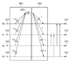
本発明の第5の実施形態の構成として、既存のリフティング演算4つを組み合せた構成を図21に示す。図21は、伝送係数=0の第5の実施形態を前段に設け、後段で既存のリフティング演算を行なう構成を付加することにより、ロスレスアダマール変換を実現した構成である。
<Fifth Embodiment>
As a configuration of the fifth embodiment of the present invention, a configuration combining four existing lifting operations is shown in FIG. FIG. 21 shows a configuration in which lossless Hadamard transform is realized by providing a fifth embodiment with transmission coefficient = 0 in the previous stage and adding a configuration in which the existing lifting calculation is performed in the subsequent stage.
図21における本第5の実施形態の第1演算部601の第1の重み係数a0,a1,a2,a3は各々 -1/2,1/2,1/2,1/2であり、第2演算部602における第2の重み係数b0,b1,b2,b3は各々 -1,+1,-1,-1である。この重み係数は a0*b0+a1*b1+a2*b2+a3*b3=0、すなわち、伝送係数=0である。該重み係数によって実現される変換は、図22に示す変換行列で表すことができる。
The first weighting coefficients a0, a1, a2, and a3 of the
図21に示す変換処理に対応する、逆変換処理の構成は図23である。これまでに説明した実施形態は伝送係数=−2の場合のみで、逆変換処理における第1及び第2の重み係数は変換処理と同じであった。しかし、伝送係数=0の場合は、変換処理と逆変換処理の間に違いがあり、逆変換処理の第2の重み係数は、変換処理の第2の重み係数に対して符号が反転している。それ以外、例えば逆変換処理の第1の演算部は変換処理と同じである。 FIG. 23 shows the configuration of the inverse conversion process corresponding to the conversion process shown in FIG. The embodiment described so far is only in the case of transmission coefficient = −2, and the first and second weighting coefficients in the inverse conversion process are the same as those in the conversion process. However, when the transmission coefficient = 0, there is a difference between the conversion process and the inverse conversion process, and the sign of the second weighting coefficient of the inverse conversion process is inverted with respect to the second weighting coefficient of the conversion process. Yes. Other than that, for example, the first calculation unit of the inverse conversion process is the same as the conversion process.
伝送係数=0である本第5の実施形態では、逆変換処理における第1の演算部601の出力は、変換処理の第1の演算部601の出力と同じである。よって、変換と逆変換の第2の重み係数の関係から、変換時に第2の重み係数を乗じて生成した値に対し、符号を反転した値を逆変換時に生成することができる。それを加算することによって、変換時に加算した値を打ち消し、元のデータを復元することができる。
In the fifth embodiment in which the transmission coefficient = 0, the output of the
ここで、図21における4つのリフティング演算の意味について説明する。図22に示す変換行列において、該変換行列の3行目と4行目の両方を、2行目に加算すると共に1行目から減算すると図12に示す右辺のアダマール変換行列になる。この3行目と4行目を、2行目に加算し、1行目から減算することに対応する処理が、図21のリフティング演算である。 Here, the meaning of the four lifting operations in FIG. 21 will be described. In the transformation matrix shown in FIG. 22, both the third row and the fourth row of the transformation matrix are added to the second row and subtracted from the first row to obtain the Hadamard transformation matrix on the right side shown in FIG. The processing corresponding to adding the third row and the fourth row to the second row and subtracting from the first row is the lifting operation of FIG.
伝送係数=0の構成のみで、有効な変換を実現することは難しいが、既存のリフティング演算と組み合せることによって、4次ロスレスアダマール変換のような有効な変換を実現できることを示した。 Although it is difficult to realize effective conversion with only the configuration of transmission coefficient = 0, it has been shown that effective conversion such as fourth-order lossless Hadamard transform can be realized by combining with existing lifting calculation.
以上で説明したロスレス変換処理(装置)を、例えばJPEG符号化で用いられるDCT変換の一部に用いることによって、ロスレスDCT変換を高速に演算でき、ロスレスとロッシー圧縮がシームレスに実現できるDCTベースのJPEG符号化が高速処理することが可能になる。 By using the lossless transformation process (apparatus) described above as a part of the DCT transformation used in, for example, JPEG encoding, the lossless DCT transformation can be calculated at high speed, and lossless and lossy compression can be realized seamlessly. JPEG encoding can be processed at high speed.
Claims (5)
前記入力端子に入力した各入力データに、それぞれに対して設定した第1の重み係数を乗じた結果を取得した後、取得した複数の結果を合算する第1の演算部と、
該第1の演算部から得られる演算結果に、前記入力データ毎に設定した第2の重み係数を乗じた結果を取得した後、それぞれの入力データに加算する第2の演算部と、
前記第1又は第2演算部のうち非整数の重み係数を乗ずる演算部に設けられ、前記非整数の演算結果を整数化する丸め処理部とを備え、
前記第1および第2の重み係数のそれぞれは、前記入力データのそれぞれに対応する前記第1の重み係数と前記第2の重み係数との積を合計した値が0又は−2となるように、設定されることを特徴とするデータ変換装置。 A data conversion device comprising an input terminal for inputting a plurality of input data and an output terminal for outputting a plurality of conversion results,
A first operation unit that obtains a result obtained by multiplying each input data input to the input terminal by a first weighting factor set for each of the input data, and then adds the obtained plurality of results ;
A second operation unit that obtains a result obtained by multiplying the operation result obtained from the first operation unit by a second weighting factor set for each input data, and then adds the result to each input data;
Provided to the arithmetic unit for multiplying the weight coefficient of the non-integer of the previous SL first or second processor, and a rounding unit for rounding the calculation result of the non-integer,
Wherein each of the first and second weighting coefficients, as a value obtained by summing the products of the first weighting factor corresponding to each and said second weighting factor of the input data is 0 or -2 the data conversion apparatus according to claim Rukoto set.
前記第1および第2の重み係数のそれぞれは、a0*b0 + a1*b1 + a2*b2 + a3*b3 が0又は−2となるように、設定されることを特徴とする請求項1に記載のデータ変換装置。Each of the first and second weighting factors is set such that a0 * b0 + a1 * b1 + a2 * b2 + a3 * b3 is 0 or −2. The data converter described.
第1の演算手段が、前記入力端子に入力した各入力データに、それぞれに対して設定した第1の重み係数を乗じた結果を取得した後、取得した複数の結果を合算する第1の演算工程と、
第2演算手段が、該第1の演算工程から得られる演算結果に、前記入力データ毎に設定した第2の重み係数を乗じた結果を取得した後、それぞれの入力データに加算する第2の演算工程と、
前記第1又は第2演算工程のうち非整数の重み係数を乗ずる演算工程において、丸め処理手段が、前記非整数の演算結果を整数化する丸め処理工程とを備え、
前記第1および第2の重み係数のそれぞれは、前記入力データのそれぞれに対応する前記第1の重み係数と前記第2の重み係数との積を合計した値が0又は−2となるように、設定されることを特徴とするデータ変換装置の制御方法。 A control method of a data conversion device comprising an input terminal for inputting a plurality of input data and an output terminal for outputting a plurality of conversion results,
A first calculation unit that obtains a result obtained by multiplying each input data input to the input terminal by a first weighting factor set for each input data, and then sums the obtained plurality of results. Process,
The second computing means obtains the result obtained by multiplying the computation result obtained from the first computation step by the second weighting factor set for each of the input data, and then adds the result to each input data. A calculation process;
In calculating step of multiplying a weighting factor of non-integer of the previous SL first or second calculation process, the rounding processing means, and a rounding step of rounding the calculation result of the non-integer,
Wherein each of the first and second weighting coefficients, as a value obtained by summing the products of the first weighting factor corresponding to each and said second weighting factor of the input data is 0 or -2 the control method of the data conversion device according to claim Rukoto set.
Priority Applications (5)
| Application Number | Priority Date | Filing Date | Title |
|---|---|---|---|
| JP2008331190A JP4594420B2 (en) | 2008-12-25 | 2008-12-25 | Data conversion apparatus and control method thereof |
| US12/636,885 US7916962B2 (en) | 2008-12-25 | 2009-12-14 | Data transforming apparatus and control method thereof |
| KR20090124531A KR101219411B1 (en) | 2008-12-25 | 2009-12-15 | Data transforming apparatus and control method thereof |
| CN200910254382XA CN101765013B (en) | 2008-12-25 | 2009-12-22 | Data transform device and control method thereof |
| EP09180473.2A EP2202644B1 (en) | 2008-12-25 | 2009-12-22 | Data transforming apparatus and control method thereof |
Applications Claiming Priority (1)
| Application Number | Priority Date | Filing Date | Title |
|---|---|---|---|
| JP2008331190A JP4594420B2 (en) | 2008-12-25 | 2008-12-25 | Data conversion apparatus and control method thereof |
Publications (3)
| Publication Number | Publication Date |
|---|---|
| JP2010154328A JP2010154328A (en) | 2010-07-08 |
| JP2010154328A5 JP2010154328A5 (en) | 2010-09-09 |
| JP4594420B2 true JP4594420B2 (en) | 2010-12-08 |
Family
ID=41820359
Family Applications (1)
| Application Number | Title | Priority Date | Filing Date |
|---|---|---|---|
| JP2008331190A Expired - Fee Related JP4594420B2 (en) | 2008-12-25 | 2008-12-25 | Data conversion apparatus and control method thereof |
Country Status (5)
| Country | Link |
|---|---|
| US (1) | US7916962B2 (en) |
| EP (1) | EP2202644B1 (en) |
| JP (1) | JP4594420B2 (en) |
| KR (1) | KR101219411B1 (en) |
| CN (1) | CN101765013B (en) |
Families Citing this family (2)
| Publication number | Priority date | Publication date | Assignee | Title |
|---|---|---|---|---|
| JP4933405B2 (en) * | 2007-11-13 | 2012-05-16 | キヤノン株式会社 | Data conversion apparatus and control method thereof |
| JP6801461B2 (en) | 2017-01-11 | 2020-12-16 | 富士通株式会社 | Information processing equipment, information processing methods, and programs |
Citations (4)
| Publication number | Priority date | Publication date | Assignee | Title |
|---|---|---|---|---|
| JP2003258645A (en) * | 2001-12-25 | 2003-09-12 | Canon Inc | Method and device for hadamard transformation processing |
| JP2004038451A (en) * | 2002-07-02 | 2004-02-05 | Canon Inc | Hadamard transformation processing method and device |
| JP2006060703A (en) * | 2004-08-23 | 2006-03-02 | Canon Inc | Data converter and data converting method |
| JP2006065678A (en) * | 2004-08-27 | 2006-03-09 | Canon Inc | Data conversion apparatus and its method |
Family Cites Families (8)
| Publication number | Priority date | Publication date | Assignee | Title |
|---|---|---|---|---|
| CN1320809C (en) * | 2001-08-29 | 2007-06-06 | 佳能株式会社 | Picture processing device and method, and computer program and storage medium |
| US7082450B2 (en) * | 2001-08-30 | 2006-07-25 | Nokia Corporation | Implementation of a transform and of a subsequent quantization |
| US7194140B2 (en) * | 2001-11-05 | 2007-03-20 | Canon Kabushiki Kaisha | Image processing apparatus and method which compresses image data of each region using a selected encoding method |
| US7188132B2 (en) * | 2001-12-25 | 2007-03-06 | Canon Kabushiki Kaisha | Hadamard transformation method and apparatus |
| JP3902968B2 (en) * | 2002-03-26 | 2007-04-11 | キヤノン株式会社 | Image processing apparatus, control method therefor, computer program, and storage medium |
| JP4366250B2 (en) * | 2003-06-23 | 2009-11-18 | キヤノン株式会社 | Data conversion processing apparatus and program |
| CN1642280B (en) * | 2004-01-01 | 2010-04-28 | 浙江大学 | Image-video-signal converting apparatus and method thereof |
| CN101106714A (en) * | 2007-07-29 | 2008-01-16 | 浙江大学 | Conversion method for video and image processing |
-
2008
- 2008-12-25 JP JP2008331190A patent/JP4594420B2/en not_active Expired - Fee Related
-
2009
- 2009-12-14 US US12/636,885 patent/US7916962B2/en not_active Expired - Fee Related
- 2009-12-15 KR KR20090124531A patent/KR101219411B1/en not_active IP Right Cessation
- 2009-12-22 CN CN200910254382XA patent/CN101765013B/en not_active Expired - Fee Related
- 2009-12-22 EP EP09180473.2A patent/EP2202644B1/en not_active Not-in-force
Patent Citations (4)
| Publication number | Priority date | Publication date | Assignee | Title |
|---|---|---|---|---|
| JP2003258645A (en) * | 2001-12-25 | 2003-09-12 | Canon Inc | Method and device for hadamard transformation processing |
| JP2004038451A (en) * | 2002-07-02 | 2004-02-05 | Canon Inc | Hadamard transformation processing method and device |
| JP2006060703A (en) * | 2004-08-23 | 2006-03-02 | Canon Inc | Data converter and data converting method |
| JP2006065678A (en) * | 2004-08-27 | 2006-03-09 | Canon Inc | Data conversion apparatus and its method |
Also Published As
| Publication number | Publication date |
|---|---|
| JP2010154328A (en) | 2010-07-08 |
| CN101765013B (en) | 2012-08-29 |
| EP2202644A2 (en) | 2010-06-30 |
| KR101219411B1 (en) | 2013-01-11 |
| US7916962B2 (en) | 2011-03-29 |
| EP2202644A3 (en) | 2017-07-12 |
| US20100166329A1 (en) | 2010-07-01 |
| EP2202644B1 (en) | 2018-08-29 |
| KR20100075734A (en) | 2010-07-05 |
| CN101765013A (en) | 2010-06-30 |
Similar Documents
| Publication | Publication Date | Title |
|---|---|---|
| CN101261619B (en) | Implementation of a transform and of a subsequent quantizatiion | |
| JP4874642B2 (en) | Lossless conversion for lossy and lossless 2D data compression | |
| JP4311759B2 (en) | Data conversion apparatus and control method thereof | |
| JPH0485621A (en) | Rounding device | |
| MX2008008987A (en) | Transforms with common factors. | |
| JP3902990B2 (en) | Hadamard transform processing method and apparatus | |
| JP3796432B2 (en) | Filter processing apparatus and filter processing method | |
| JP4594420B2 (en) | Data conversion apparatus and control method thereof | |
| JP6480695B2 (en) | Apparatus and method for compact bit-plane data compression | |
| KR20070029524A (en) | Apparatus and method for transcoding mpeg-2 data into h.264 data | |
| JP4366250B2 (en) | Data conversion processing apparatus and program | |
| JP4933405B2 (en) | Data conversion apparatus and control method thereof | |
| KR100402734B1 (en) | the fixed point multiplier using a coded multiplicnd and the method thereof | |
| Al-Khafaji | Hybrid image compression based on polynomial and block truncation coding | |
| JP5451171B2 (en) | Data conversion processing device and data conversion processing method | |
| Al-Timimi | Lossy Image Compression based on Differential Coding and Linear Polynomial | |
| JP2017055270A (en) | Information processing apparatus and information processing system | |
| JP2763133B2 (en) | Two-dimensional linear transformation device, two-dimensional linear inverse transformation device, and data compression / decompression system equipped with these devices | |
| JP6102707B2 (en) | Digital encoding device | |
| KR100240002B1 (en) | Image signal compression and discrete cosine transform device for decompression | |
| JP4378407B2 (en) | Data conversion processing apparatus and method | |
| Mosa | COLOR IMAGE COMPRESSION BASED ON ABSOLUTE MOMENT BLOCK TRUNCATION CODING USING DELTA ENCODING AND HUFFMAN CODING | |
| JP2011257806A (en) | Data conversion method, conversion device, and image encoding apparatus | |
| Vural | VLSI implementation of lossless JPEG2000 image coding system | |
| Tang et al. | An Enhanced Resolution Three-Dimensional Transformation Method Based on Discrete Wavelet Transform |
Legal Events
| Date | Code | Title | Description |
|---|---|---|---|
| A521 | Request for written amendment filed |
Free format text: JAPANESE INTERMEDIATE CODE: A523 Effective date: 20100722 |
|
| A621 | Written request for application examination |
Free format text: JAPANESE INTERMEDIATE CODE: A621 Effective date: 20100722 |
|
| A871 | Explanation of circumstances concerning accelerated examination |
Free format text: JAPANESE INTERMEDIATE CODE: A871 Effective date: 20100722 |
|
| A975 | Report on accelerated examination |
Free format text: JAPANESE INTERMEDIATE CODE: A971005 Effective date: 20100809 |
|
| TRDD | Decision of grant or rejection written | ||
| A01 | Written decision to grant a patent or to grant a registration (utility model) |
Free format text: JAPANESE INTERMEDIATE CODE: A01 Effective date: 20100820 |
|
| A01 | Written decision to grant a patent or to grant a registration (utility model) |
Free format text: JAPANESE INTERMEDIATE CODE: A01 |
|
| A61 | First payment of annual fees (during grant procedure) |
Free format text: JAPANESE INTERMEDIATE CODE: A61 Effective date: 20100916 |
|
| FPAY | Renewal fee payment (event date is renewal date of database) |
Free format text: PAYMENT UNTIL: 20130924 Year of fee payment: 3 |
|
| R150 | Certificate of patent or registration of utility model |
Ref document number: 4594420 Country of ref document: JP Free format text: JAPANESE INTERMEDIATE CODE: R150 Free format text: JAPANESE INTERMEDIATE CODE: R150 |
|
| LAPS | Cancellation because of no payment of annual fees |