JP4593926B2 - Email management service - Google Patents
Email management service Download PDFInfo
- Publication number
- JP4593926B2 JP4593926B2 JP2003570219A JP2003570219A JP4593926B2 JP 4593926 B2 JP4593926 B2 JP 4593926B2 JP 2003570219 A JP2003570219 A JP 2003570219A JP 2003570219 A JP2003570219 A JP 2003570219A JP 4593926 B2 JP4593926 B2 JP 4593926B2
- Authority
- JP
- Japan
- Prior art keywords
- message
- address
- data
- mail server
- messages
- Prior art date
- Legal status (The legal status is an assumption and is not a legal conclusion. Google has not performed a legal analysis and makes no representation as to the accuracy of the status listed.)
- Expired - Lifetime
Links
- 238000000034 method Methods 0.000 claims abstract description 180
- 230000008569 process Effects 0.000 claims abstract description 150
- 238000007726 management method Methods 0.000 claims abstract description 118
- 230000005540 biological transmission Effects 0.000 claims abstract description 41
- 239000011159 matrix material Substances 0.000 claims abstract description 33
- 230000009471 action Effects 0.000 claims description 50
- 238000012545 processing Methods 0.000 claims description 45
- 230000008859 change Effects 0.000 claims description 4
- 238000001914 filtration Methods 0.000 claims description 4
- 230000001629 suppression Effects 0.000 claims description 4
- 238000013213 extrapolation Methods 0.000 claims 2
- 230000008520 organization Effects 0.000 description 23
- 238000012544 monitoring process Methods 0.000 description 14
- 238000010586 diagram Methods 0.000 description 13
- 241000700605 Viruses Species 0.000 description 10
- 230000004044 response Effects 0.000 description 7
- 230000000694 effects Effects 0.000 description 6
- 238000001514 detection method Methods 0.000 description 5
- 230000001502 supplementing effect Effects 0.000 description 5
- 230000006399 behavior Effects 0.000 description 3
- 239000003795 chemical substances by application Substances 0.000 description 3
- 230000009931 harmful effect Effects 0.000 description 3
- 238000004891 communication Methods 0.000 description 2
- 238000012790 confirmation Methods 0.000 description 2
- 230000003111 delayed effect Effects 0.000 description 2
- 230000001627 detrimental effect Effects 0.000 description 2
- 238000012986 modification Methods 0.000 description 2
- 230000004048 modification Effects 0.000 description 2
- 239000013589 supplement Substances 0.000 description 2
- 238000012546 transfer Methods 0.000 description 2
- 230000001960 triggered effect Effects 0.000 description 2
- 208000036142 Viral infection Diseases 0.000 description 1
- 230000002730 additional effect Effects 0.000 description 1
- 230000000903 blocking effect Effects 0.000 description 1
- 238000010276 construction Methods 0.000 description 1
- 230000003247 decreasing effect Effects 0.000 description 1
- 230000001934 delay Effects 0.000 description 1
- 238000011156 evaluation Methods 0.000 description 1
- 238000003780 insertion Methods 0.000 description 1
- 230000037431 insertion Effects 0.000 description 1
- 230000007246 mechanism Effects 0.000 description 1
- 230000002265 prevention Effects 0.000 description 1
- 230000000135 prohibitive effect Effects 0.000 description 1
- 238000012552 review Methods 0.000 description 1
- 238000012360 testing method Methods 0.000 description 1
- 238000010200 validation analysis Methods 0.000 description 1
- 230000009385 viral infection Effects 0.000 description 1
Images


Classifications
-
- G06Q50/60—
-
- H—ELECTRICITY
- H04—ELECTRIC COMMUNICATION TECHNIQUE
- H04L—TRANSMISSION OF DIGITAL INFORMATION, e.g. TELEGRAPHIC COMMUNICATION
- H04L51/00—User-to-user messaging in packet-switching networks, transmitted according to store-and-forward or real-time protocols, e.g. e-mail
- H04L51/21—Monitoring or handling of messages
- H04L51/212—Monitoring or handling of messages using filtering or selective blocking
-
- H—ELECTRICITY
- H04—ELECTRIC COMMUNICATION TECHNIQUE
- H04L—TRANSMISSION OF DIGITAL INFORMATION, e.g. TELEGRAPHIC COMMUNICATION
- H04L63/00—Network architectures or network communication protocols for network security
- H04L63/14—Network architectures or network communication protocols for network security for detecting or protecting against malicious traffic
- H04L63/1441—Countermeasures against malicious traffic
- H04L63/145—Countermeasures against malicious traffic the attack involving the propagation of malware through the network, e.g. viruses, trojans or worms
-
- G06Q50/40—
-
- H—ELECTRICITY
- H04—ELECTRIC COMMUNICATION TECHNIQUE
- H04L—TRANSMISSION OF DIGITAL INFORMATION, e.g. TELEGRAPHIC COMMUNICATION
- H04L51/00—User-to-user messaging in packet-switching networks, transmitted according to store-and-forward or real-time protocols, e.g. e-mail
- H04L51/21—Monitoring or handling of messages
- H04L51/23—Reliability checks, e.g. acknowledgments or fault reporting
Abstract
Description
ここで開示される実施形態は、一般にEメール管理システムに関し、より詳細には、トラフィックの監視及び管理に基づいて電子メッセージを監視し、フィルタリングするための、トラフィックの監視及び管理を用いるEメール管理システム(EMS)に関する。 Embodiments disclosed herein generally relate to email management systems, and more particularly, email management using traffic monitoring and management to monitor and filter electronic messages based on traffic monitoring and management. It relates to a system (EMS).
Eメール管理は、通常は、ユーザ/加入者を有するISPにより、又はEメールユーザを雇用する会社によってなされる。Eメール管理の一部には、スパム又はウィルス制御のためのフィルタリングが含まれるが、こうしたEメール管理がISPで又は会社のサーバ位置で行われるときには、貴重な通信帯域幅及び計算リソースが、ルーティングすること、解析すること、その他のスプリアス(spurious)Eメールトラフィックを取り扱うことに消費されてしまう。現在のEメール管理システムはさらに、リアルタイムの監視、フィードバック、及びEメールトラフィック又はSMTP接続状況に関するルールのアップデートの欠如により特徴付けられる。Eメールトラフィック状況の管理及び監視は、通常は、人間の介入によってなされる。
スパム又はウィルスを遮断するためのその他の現在のシステムには、おとりのEメールアドレスをインターネット内におき、このおとりのEメールアドレスがスパム収集体として働くシステムがある。次いで、人間のエディタが受信メッセージを調べ、それらを分類整理し、こうしたジャンクメール・メッセージとそれらのチェックサムのデータベースを作る。次いで、作成したデータベースをサービスの加入者に配布し、顧客宅で受信されたメッセージの各々がウィルス/スパムデータベースと対照してチェックされる。この場合もまた、インターネットの新しいウィルス及びスパムメッセージの検出及び監視はリアルタイムではなく、顧客宅のメールサーバは依然として全てのスプリアスEメールを受信するので、全ての受信Eメールを解析してデータベースに適合するものがあるかどうか確かめなければならない。
Email management is usually done by an ISP with users / subscribers or by a company that employs email users. Part of email management includes filtering for spam or virus control, but when such email management is performed at an ISP or at a company server location, valuable communication bandwidth and computational resources are routed. Consuming, analyzing, and handling other spurious email traffic. Current email management systems are further characterized by a lack of real-time monitoring, feedback, and rules updates regarding email traffic or SMTP connection status. Management and monitoring of email traffic conditions is usually done by human intervention.
Other current systems for blocking spam or viruses include a system that places a decoy email address in the Internet, and this decoy email address serves as a spam collector. A human editor then examines the received messages, sorts them, and creates a database of these junk mail messages and their checksums. The created database is then distributed to service subscribers, and each message received at the customer's home is checked against the virus / spam database. Again, the detection and monitoring of new Internet virus and spam messages is not real-time and the customer's mail server still receives all spurious emails, so all incoming emails are analyzed and matched to the database. You have to make sure you have something to do.
(関連出願のクロスリファレンス)
本出願は、2002年2月19日付けの「E−Mail Management Services」と題する本発明の譲受人に譲渡された米国特許仮出願第60/357,893号に基づく優先権を主張するものであり、該特許出願を引用によりここに組み入れる。
(Cross-reference of related applications)
This application claims priority from US Provisional Application No. 60 / 357,893, assigned to the assignee of the present invention entitled "E-Mail Management Services", dated February 19, 2002. Yes, the patent application is incorporated herein by reference.
(発明の概要)
上述の従来技術の欠点に対処するために、本発明は、1つの態様において、送信メールサーバから受信メールサーバへの電子メッセージの伝送を管理するコンピュータ処理と共に用いられるトラフィックモニタを提供し、送信メールサーバから送信されたメッセージは、送信メールサーバに関連する発信元データと、受信メールサーバに関連する宛先データとを含む。一実施形態においては、トラフィックモニタは、複数の受信電子メッセージの発信元データ及び宛先データを格納するためのデータ・マトリックスと、該マトリックスに結合されたインターフェースとを含む。この実施形態においては、インターフェースは、発信元データ及び宛先データに対して、コンピュータ処理により与えられ且つ複数の電子メッセージに基づいたメタデータを補充することを容易にし、かつこの複数の電子メッセージの処理に用いるために発信元データ及び宛先データ並びにメタデータに容易にアクセスするように構成される。
別の態様においては、本発明は、送信メールサーバから受信メールサーバへの電子メッセージの伝送を管理するコンピュータ処理と共に用いられる方法を提供し、送信メールサーバから送信されたメッセージは、送信メールサーバに関連する発信元データと、受信メールサーバに関連する宛先データとを含む。一実施形態においては、この方法は、接続プロセスを完了することなく複数の受信電子メッセージの発信元データ及び宛先データをリアルタイムで収集し、保存して、該発信元データ及び宛先データに対して、コンピュータ処理により与えられ且つ複数の電子メッセージに基づいたメタデータを補充することを含む。さらに、この方法は、コンピュータ処理において、発信元データ及び宛先データ並びにメタデータに基づき複数の電子メッセージを解析し、処理することを含む。
(Summary of Invention)
To address the shortcomings of the prior art described above, the present invention, in one aspect, provides a traffic monitor for use with a computer process that manages the transmission of electronic messages from a sending mail server to a receiving mail server. The message transmitted from the server includes transmission source data related to the transmission mail server and destination data related to the reception mail server. In one embodiment, the traffic monitor includes a data matrix for storing source data and destination data for a plurality of received electronic messages, and an interface coupled to the matrix. In this embodiment, the interface facilitates supplementing the source data and destination data with metadata provided by computer processing and based on the plurality of electronic messages, and processing of the plurality of electronic messages. For easy access to source and destination data and metadata.
In another aspect, the present invention provides a method for use in conjunction with a computer process that manages transmission of an electronic message from a sending mail server to a receiving mail server, wherein messages sent from the sending mail server are sent to the sending mail server. It includes related source data and destination data related to the incoming mail server. In one embodiment, the method collects and stores source data and destination data of a plurality of received electronic messages in real time without completing the connection process, for the source data and destination data, Including replenishing metadata provided by a computer process and based on a plurality of electronic messages. Further, the method includes analyzing and processing a plurality of electronic messages based on the source data, the destination data, and the metadata in a computer process.
さらに別の態様においては、本発明は、送信メールサーバから受信メールサーバへの電子メッセージの伝送を管理するのに用いられる電子メッセージ管理システム(EMS)を提供し、送信メールサーバから送信されたメッセージは、送信メールサーバに関連する発信元データと、受信メールサーバに関連する宛先データとを含む。一実施形態においては、EMSは、複数の受信電子メッセージの発信元データ及び宛先データを保存するためのデータ・マトリックスを有するトラフィックモニタと、データ・マトリックスへのアクセスを容易にするためのインターフェースとを含む。また、EMSは、複数の電子メッセージから外挿されたメタデータを発信元データ及び宛先データに対して補充するように構成され且つインターフェースに結合された、メッセージ取扱いプロセスを含む。この実施形態においては、EMSはさらに、発信元データ及び宛先データ並びにメタデータにアクセスして、それらに基づく処理命令を生成するように構成され且つインターフェースに結合された、インタープリタ・プロセスを含む。こうした実施形態においては、メッセージ取扱いプロセスはさらに、処理命令に基づいて複数の電子メッセージを処理するように構成される。
別の態様においては、本発明は、送信メールサーバから受信メールサーバへの電子メッセージの伝送を管理する方法を提供し、送信メールサーバから送信されたメッセージは、送信メールサーバに関連する発信元データと、受信メールサーバに関連する宛先データとを含む。一実施形態においては、この方法は、複数の受信電子メッセージの発信元データ及び宛先データをデータ・マトリックスに保存し、複数の電子メッセージからメタデータを外挿することを含む。さらに、この方法は、発信元データ及び宛先データに対してメタデータを補充することと、インターフェースを介して発信元データ及び宛先データに並びにメタデータにアクセスすることを含む。この方法はまた、発信元データ及び宛先データ並びにメタデータに基づく処理命令を生成し、該処理命令に基づき複数の電子メッセージを処理することを含む。
In yet another aspect, the present invention provides an electronic message management system (EMS) used to manage transmission of electronic messages from a sending mail server to a receiving mail server, and messages sent from the sending mail server. Includes transmission source data related to the transmission mail server and destination data related to the reception mail server. In one embodiment, the EMS includes a traffic monitor having a data matrix for storing source data and destination data of a plurality of received electronic messages, and an interface for facilitating access to the data matrix. Including. The EMS also includes a message handling process configured to supplement the source data and destination data with metadata extrapolated from the plurality of electronic messages and coupled to the interface. In this embodiment, the EMS further includes an interpreter process that is configured and coupled to the interface to access the source and destination data and metadata and generate processing instructions based thereon. In such embodiments, the message handling process is further configured to process a plurality of electronic messages based on the processing instructions.
In another aspect, the present invention provides a method for managing transmission of an electronic message from a sending mail server to a receiving mail server, wherein the message sent from the sending mail server is source data associated with the sending mail server. And destination data related to the received mail server. In one embodiment, the method includes storing source data and destination data of a plurality of received electronic messages in a data matrix and extrapolating metadata from the plurality of electronic messages. In addition, the method includes supplementing the metadata for the source data and destination data, and accessing the source data and destination data as well as the metadata via the interface. The method also includes generating processing instructions based on the source and destination data and metadata and processing the plurality of electronic messages based on the processing instructions.
さらに別の実施形態においては、本発明は、送信メールサーバから受信メールサーバへの電子メッセージの伝送を管理するのに用いられるEMSを提供する。一実施形態においては、EMSは、複数の受信電子メッセージから送信メールサーバに関連する発信元データと受信メールサーバに関連する宛先データとを抽出するように構成された接続管理モジュールを含む。さらに、EMSは、発信元データ及び宛先データを保存するためのデータ・マトリックスと、該データ・マトリックスと接続管理モジュールとの間に結合されたインターフェースとを含む。こうした実施形態においては、インターフェースは、複数の受信電子メッセージから外挿されたメタデータを発信元データ及び宛先データに対して補充することを容易にし、かつ発信元データ及び宛先データ並びにメタデータへのアクセスを容易にするように構成される。こうした実施形態においては、接続管理モジュールはさらに、発信元データ及び宛先データ並びにメタデータに基づいて、送信メールサーバからの複数の受信電子メッセージのいずれかを受諾するように構成される。
さらに別の実施形態においては、本発明は、送信メールサーバから受信メールサーバへの電子メッセージの伝送を管理する方法を提供する。一実施形態においては、この方法は、複数の受信電子メッセージから送信メールサーバに関連する発信元データと受信メールサーバに関連する宛先データとを抽出することを含む。この方法はまた、複数の電子メッセージから外挿されたメタデータを発信元データ及び宛先データに対して補充し、発信元データ及び宛先データ並びにメタデータに基づいて、送信メールサーバから複数の電子メッセージのいずれかを受諾することを含む。
In yet another embodiment, the present invention provides an EMS used to manage the transmission of electronic messages from a sending mail server to a receiving mail server. In one embodiment, the EMS includes a connection management module configured to extract source data associated with the outgoing mail server and destination data associated with the incoming mail server from the plurality of received electronic messages. In addition, the EMS includes a data matrix for storing source data and destination data, and an interface coupled between the data matrix and the connection management module. In such an embodiment, the interface facilitates supplementing the source data and destination data with metadata extrapolated from multiple received electronic messages, and to the source data and destination data and metadata. Configured to facilitate access. In such embodiments, the connection management module is further configured to accept any of a plurality of received electronic messages from the outgoing mail server based on the source data and destination data and metadata.
In yet another embodiment, the present invention provides a method for managing transmission of electronic messages from a sending mail server to a receiving mail server. In one embodiment, the method includes extracting source data associated with the outgoing mail server and destination data associated with the incoming mail server from the plurality of received electronic messages. The method also supplements the metadata extrapolated from the plurality of electronic messages to the source data and the destination data, and based on the source data, the destination data and the metadata, the plurality of electronic messages from the sending mail server. Including accepting either.
さらに別の実施形態においては、本発明は、送信メールサーバから受信メールサーバへの電子メッセージの伝送を管理するのに用いるEMSを提供する。一実施形態においては、EMSは、送信メールサーバに関連する発信元データと受信メールサーバに関連する宛先データとを保存するためのデータ・マトリックスを含む。EMSはまた、複数の電子メッセージから外挿されたメタデータを発信元データ及び宛先データに対して補充することを容易にし、かつ発信元データ及び宛先データ並びにメタデータに容易にアクセスするように構成され且つデータ・マトリックスに結合された、インターフェースを含む。この実施形態においては、EMSはさらに、発信元データ及び宛先データ並びにメタデータに基づいて、複数の受信電子メッセージのいずれかを受信メールサーバに配信するように構成され、且つインターフェースに結合された配信管理モジュールを含む。 In yet another embodiment, the present invention provides an EMS for use in managing the transmission of electronic messages from a sending mail server to a receiving mail server. In one embodiment, the EMS includes a data matrix for storing source data associated with the outgoing mail server and destination data associated with the incoming mail server. The EMS is also configured to facilitate supplementing the source data and destination data with metadata extrapolated from multiple electronic messages and to easily access the source data and destination data and metadata. And an interface coupled to the data matrix. In this embodiment, the EMS is further configured to deliver any of the plurality of received electronic messages to the receiving mail server based on the source and destination data and metadata, and coupled to the interface. Includes management module.
さらに別の実施形態においては、本発明は、送信メールサーバから受信メールサーバへの電子メッセージの伝送を管理するのに用いる方法を提供する。一実施形態においては、この方法は、複数の受信電子メッセージからの送信メールサーバに関連する発信元データと受信メールサーバに関連する宛先データとを保存することを含む。この方法はまた、複数の電子メッセージから外挿されたメタデータを発信元及び宛先データに対して補充することを含む。こうした実施形態においては、この方法はさらに、発信元データ及び宛先データ並びにメタデータに基づいて、複数の電子メッセージのいずれかを受信メールサーバに配信することを含む。
上記は、本発明の好ましい選択的な特徴を概説するものであり、当業者であれば、以下の本発明の詳細を良く理解することができるであろう。以下に、本発明の特許請求の主題となる本発明の付加的な特徴を説明する。当業者であれば、本発明と同じ目的を実行するために他の構造を設計し又は修正するための基礎として、開示された概念及び特定の実施形態を直ちに使用できることを認識するであろう。また、当業者であれば、こうした均等構成が、本発明の精神及び範囲から逸脱するものではないことを理解するであろう。
In yet another embodiment, the present invention provides a method used to manage the transmission of electronic messages from a sending mail server to a receiving mail server. In one embodiment, the method includes storing source data associated with the outgoing mail server and destination data associated with the incoming mail server from the plurality of received electronic messages. The method also includes supplementing the source and destination data with metadata extrapolated from the plurality of electronic messages. In such embodiments, the method further includes delivering any of the plurality of electronic messages to the receiving mail server based on the source and destination data and the metadata.
The foregoing outlines preferred optional features of the invention and will enable those skilled in the art to better understand the details of the invention that follows. Additional features of the invention will be described hereinafter that form the subject of the claims of the invention. One skilled in the art will recognize that the disclosed concepts and specific embodiments can be readily used as a basis for designing or modifying other structures to accomplish the same purpose as the present invention. Those skilled in the art will also appreciate that such equivalent constructions do not depart from the spirit and scope of the invention.
本発明のより完全な理解のために、添付の図面と組み合わされた以下の詳細な説明について言及する。種々の特徴が正確なスケールで描かれているわけではないことを強調しておく。実際には、種々の特徴の寸法は、説明を簡単にするために任意に増減されている場合がある。さらに、説明を簡単にするために幾つかのコンポーネントが図示されていない場合があることを強調しておく。添付の図面と組み合わされた以下の詳細な説明について言及する。
最初に図1を参照すると、図示されているのは、インターネット101又は他のコンピュータ・ネットワークにわたるEメールメッセージの配信のための従来技術のシステム100である。送信メールサーバ102a、102b(関連する発信元インターネット・プロトコル(IP)アドレスを有する)及び受信メールサーバ102c、102d(関連する宛先IPアドレスを有する)、又は他のメッセージ・ゲートウェイは、電子メール(すなわち「Eメール」)のような電子メッセージを、送信顧客マシン104a−104dと受信顧客マシン104e−104hとの間で、又は移動電話、ページャ(携帯無線呼出し器)、及び/又はハンドヘルドコンピュータのような他の装置との間で配信できるようにする。通常のシステムによれば、Eメールの伝送方向は逆であってもよく、その場合、送信マシン及びサーバは、受信マシン及びサーバとなり、逆もまた同様である。
For a more complete understanding of the present invention, reference is made to the following detailed description taken in conjunction with the accompanying drawings. It is emphasized that the various features are not drawn to scale. In practice, the dimensions of the various features may be arbitrarily increased or decreased for ease of explanation. It is further emphasized that some components may not be shown for ease of explanation. Reference is made to the following detailed description in conjunction with the accompanying drawings.
Referring initially to FIG. 1, illustrated is a
Eメールメッセージは、典型的には、顧客マシン104上で動作するアプリケーションによって作成される。メッセージの作成が完了すると、ユーザは、完成したメッセージをメールサーバ102にアップロードする。一実施形態においては、メールサーバ102は、インターネットサービスプロバイダ(ISP)か、又はユーザが働く私法人が所有する。ダイヤルアップ、デジタル加入者線システム(DSL)、インターネットケーブルを介して、又は他の適切な手段により、ユーザ顧客マシン104がメールサーバ102に接続される。Eメールフォーマットの1つの標準は、RFC2822によって過去のものとなったRFC822により説明され、これらはそれぞれ、インターネット技術特別調査委員会(「IETF」)により公布された、標準及び提案された標準である。Eメールメッセージを送信メールサーバ102から受信メールサーバ102に伝送するためのプロトコルは、RFC2821によって過去のものとなったRFC821により説明され、これらもそれぞれIETFの標準及び提案された標準である。これらの標準は、WWW.ietf.orgで見ることができる。RFC821及びRFC822標準、ならびにRFC2821及びRFC2822提案標準の主題を、引用により本開示に組み入れる。提案された標準が、2001年4月発行のバージョンから更新される場合には、引用によりここに組み入れられるのは、これらの提案された標準の2001年4月バージョンの主題である。RFC821及びRFC2821文書は、シンプル・メール・トランスポート・プロトコル(「SMTP」)を説明するものであり、典型的には、そのプロトコルによって、Eメールメッセージがインターネット上で運ばれる。
The email message is typically created by an application running on the customer machine 104. When the creation of the message is completed, the user uploads the completed message to the
SMTPサーバ及びSMTP顧客(SMTP顧客は、ネットワークコンピュータであって、顧客マシン104とは混同されない)は、メール配達サービスを与え、それによりメール転送エージェント(「MTA」)として働く。メール・ユーザ・エージェント(「MUA」又は「UA」)は、普通は、メールの発信元及び宛先と考えられる。発信元においては、MUAは、発信元メールサーバ102a、102bであって、ユーザから送信されたメールを収集し、それをネットワーク101内のMTAに渡すことができる。最後の(「配信」)MTAは、メールをMUAに渡すものと考えられ、ユーザのメールボックスの中のユーザのメールを保持する宛先メールサーバ102c、102dとなるであろう。
SMTPメール配達プロトコルは、メッセージを送信者からEメール受信者にルーティングするのにドメイン名を用いる。特定のドメイン名に対応するTCP/IPアドレスの分散型データベースが、インターネット101を横断するドメイン名サーバ(「DNS」)108に維持される。したがって、Eメールを宛先にルーティングするために、発信元メールサーバ102a、102bが、通常は送信ユーザによって指定されるアドレスを受け取り、特定のアドレス指定されたドメイン名に割り当てられることになるIPアドレスを、DNSサーバ108に問い合わせる。本明細書で用いられる「アドレス」は、メールが送信されることになるユーザ、メールを送信するユーザ又は発信元、或いはメールが置かれることになる場所を識別する文字列である。「メールボックス」という用語は、保管所のことをいう。これら2つの用語は、典型的には、メールがおかれる場所(メールボックス)と、その場所の参照(アドレス)との区別が重要でない場合には、交換可能に用いられる。アドレスは、普通は、ユーザ及びドメイン指定からなるが、アドレスは、使用とアドレス形式に応じて異なる形態をとってもよい。標準的なメールボックス命名規則は、「ローカル部分@ドメイン」と定義され、最新の使用は、単純な「ユーザ名」より非常に幅広い組の適用を可能にする。アドレスのローカル部分は、典型的には、アドレスのドメイン部分において指定されるホストによってのみ解釈され割り当てられる意味規則(セマンティクス)である。対照的に、標準的なインターネット・プロトコル(IP)アドレスは、典型的には、発信元又は宛先サーバを識別する特定の数の列である。
発信元メールサーバ102a、102bが、Eメールが配信されることになるドメインを処理のために字句的に識別すると、DNSサーバ108を通じてDNS検索が行われ、ドメイン名が解析される。次いで、Eメール110が、発信元メールサーバ102a、102bからインターネット101経由で識別されたドメインに送られる。
SMTP servers and SMTP customers (SMTP customers are network computers and are not confused with customer machines 104) provide mail delivery services, thereby acting as mail transfer agents ("MTA"). Mail user agents ("MUA" or "UA") are usually considered mail sources and destinations. At the sender, the MUA is a
The SMTP mail delivery protocol uses domain names to route messages from senders to email recipients. A distributed database of TCP / IP addresses corresponding to a particular domain name is maintained in a domain name server (“DNS”) 108 that traverses the
When the
次に図2を参照すると、図示されているのは、インターネット101と受信メールサーバ202との間にアクティブな電子メッセージ(例えばEメール)管理システム(EMS)203が与えられる実施形態のブロック図200である。本発明のEMS203は、該EMSが、管理プロセスの種々の段階で人間の介入を必要とすることなく、電子メッセージの試行された伝送を常に管理するので、「アクティブ」であり、自動化されている。その意味で、ここで開示された原理に係るEMS203は、自動化されており、メッセージの配信をリアルタイムで管理するように構成される。EMSシステムは、送信者と受信者との間のSMTP接続の各々が処理されるときに処理ステップを実行することにより、状態を解釈し、パターンを解析し、受信サーバ202へのデータの配信を管理することができる。従来のEメールサーバは、典型的には、メッセージデータを受け取り、解析を行う前に該メッセージをディスクに書き込むことになる。EMS203は、SMTPトランザクションの各段階で管理ステップを実行して、セキュリティと管理を与えながら宛先サーバ202に対する影響を最小にすることができる。メールサーバ202に宛てられ、それにより受信顧客端末204に宛てられるメールが、EMS203を通してルーティングされるためには、目標とされたメールサーバ202のドメイン名に関連するDNS108における数値IPアドレスが、EMS203の数値アドレスを反映するように更新される。例えば、メールサーバ202のドメイン名が「anywhere.com」であり、メールサーバ202とEMS203の数値IPアドレスが、それぞれ「1234.5678.9876.5432」及び「9876.5432.1234.5768」であると仮定する。そのとき、分散型DNSデータベース108における「anywhere.com」についてのレコードは、「1234.5678.9876.5432」ではなく、EMSの数値アドレス「9876.5432.1234.5768」を反映するように更新されることになる。
この図は、EMS203を、メールサーバ202に物理的に隣接するものとして示しているが、こうした配置は、図示する目的のためのものである。EMS203は、インターネット101上のどこかに配置することができる。EMS203は、位置「A」(ファイアウォールの外側)か、又は位置「B」(ファイアウォールの内側)における随意的なファイアウォール210位置によって示されるように、メールサーバ202のファイアウォール210に関連する外部か又は内部のいずれかに配置することもできる。或いは、EMS203は、メールサーバ202と同じ物理的マシン上で動作することもできる。
Referring now to FIG. 2, illustrated is a block diagram 200 of an embodiment in which an active electronic message (eg, email) management system (EMS) 203 is provided between the
Although this figure shows the
次に図3を参照すると、図示されているのは、EMS203のブロック図300を含む、より詳細な図である。実際のEMSシステム203と同じ特定のサーバマシン上に、管理コンソールウェブページ316(管理モジュール318を含む)を置いて、EMS203がどのように受信電子メッセージを処理するか設定するのを助ける管理アクセスツールを与えることができる。EMS203とメールサーバ102a、102cとの間の接続は、インターネットか又はSMTP接続を通じて行うことができる。既に述べたように、EMS203は、メールサーバ102a、102cの1つがある又はない特定のファイアウォールの内部に又は外部に存在させることができる。
通常、図3に示されたシステムは、「送信」メールサーバ102aからのメールを取り扱う。「送信側」としての1つのメールサーバと、「受信側」としての他のメールサーバの指定は、任意のものである。事実上、両方のメールサーバ102a、102cは、一般に、メールサーバ102a及び102cの送信及び受信顧客104a、104eの間で電子メッセージの送信側と受信側との両方として働くことになる。図示された実施形態においては、メールサーバ102a、102cのドメイン名の少なくとも1つは、DNS分散型データベース及びそのサーバ108においてEMS203に関連付けられることになる。管理コンソール316を採用する実施形態においては、コンソール316は、ユーザに送信された疑わしいウィルス及びスパムEメール、ディレクトリ獲得攻撃、又は望ましくないコンテンツ又は配信試行に関する情報のような、特定のユーザ又はユーザのグループに宛てて受信する電子メッセージの形式に関する、EMS203からの情報を受信する。ユーザ又は組織のためにEMS203によって適用されるフィルタリングのパラメータを設定するのに用いられるのが、管理コンソール316である。管理コンソール316は、特定のドメインから送信された法外な数のEメール又は他の不審なトラフィックパターンのような、システムのトラフィックパターンに関するEMS203からの情報を受信する。管理コンソール316は、ウェブサーバ上か又は随意的にEMS203と同じ中間プラットフォーム上で動作する「管理」ソフトウェアモジュール318を有するウェブベースのアプリケーションであってもよい。
Referring now to FIG. 3, illustrated is a more detailed view, including a block diagram 300 of
Typically, the system shown in FIG. 3 handles mail from the “send”
図3において、EMS203は、相互接続された多くのソフトウェアモジュールを有するメッセージ取扱いコンピュータ処理320を含むものとして示されている。メッセージ取扱い処理320におけるこれらの種々のソフトウェアモジュールのレイアウトは、こうしたソフトウェアモジュールを動作させるマシンの物理構造を特定的に示すものではない。処理320に含まれるモジュールの1つは、接続管理モジュール又は簡単には接続マネジャ322である。接続マネジャ322は、UA/メールサーバ102a(又はメール転送エージェント)からの受信SMTP接続をセットアップし、監視する役割を果たす。接続マネジャ322は、EMS203への入口点であり、受信SMTP接続試行及びEメールメッセージを監視する。処理320はさらにトラフィックモニタ340に接続され、該トラフィックモニタが、受信SMTP接続データ、メッセージメタデータ、及びメッセージ配信情報を収集する。
In FIG. 3, the
特定の形式のソフトウェア・デーモンとすることができるインタープリタ・プロセス350がさらに与えられる。インタープリタ・プロセス350は、トラフィックモニタ340におけるデータと相互に作用して、動作可能なメッセージのトラフィック内のメッセージパターンを認識する。より具体的には、それら全てが処理320の一部を構成する、接続マネジャ322、Eメールハンドラ326、アプリケーション332、及び配信管理モジュール(又は簡単には配信マネジャ324)が、受信メッセージの処理中に、発信元及び宛先データ並びにメタデータをトラフィックモニタ340に書き込む。発信元及び宛先データは、送信メールサーバ102aに関連する発信元データと、受信メールサーバ104eに関連する宛先データとからなる。メタデータは、処理320によって、コンテンツの形式又はサイズにより定められる特定のメッセージのような望ましくないメッセージを検出するプログラム・スレッドであるアプリケーション332を用いて電子メッセージから外挿される。表1は、EMS203により生成されたメタデータのより詳細な例を示すが、このリストは、他を除外することを意図されているものではない。
An
(表1)

電子メッセージのパターン、又はさらにはメッセージを送信するユーザの挙動を判断するために、インタープリタ・プロセス350が、トラフィックモニタ340に書き込まれた発信元及び宛先データ並びにメタデータの両方を解析する。例えば、多数のメッセージが同じ外部UAメールサーバ102aから受信する場合、これは、スパム攻撃、又は他のサービスの拒絶、或いは望ましくない配信アクティビティを示すであろう。インタープリタ・プロセス350は、トラフィックモニタ340に格納された発信元及び宛先データ並びにメタデータのパターンを通じてこうした傾向に気付き、メールハンドラ326における厄介なEメールを遮断するアクションを開始することができる。好都合な実施形態においては、インタープリタ・プロセス350は、こうしたタスクのために作成された特定のソフトウェア・デーモンであるが、本発明は、どんな特定の実施形態にも限定されるものではない。インタープリタ・プロセス350が発信元及び宛先データ並びにメタデータに基づいて検出することができる他のパターン又は状態の例には、この限りではないが以下の事象、すなわち、
・サーバ上の有効なアドレスのリストをコンパイルするべく、統計学上顕著な割合の配信試行が正当でないユーザに向けられるディレクトリ獲得攻撃の検出、
・同じ又は同様のメッセージが同じユーザ又はユーザグループに繰り返し配信されるEメール爆弾の検出、
・発信元IPアドレスから送信される顕著な割合のデータがスパムであるか又はそうでなければ望ましくないEメールであるスパム攻撃、
・発信元IPアドレスから送信される顕著な割合のデータがウィルス感染したものであるウィルス攻撃、
・送信IPアドレスが繰り返し接続され、その接続がオープンに保たれるか、又は意味のあるデータが配信されない、サービス接続要求の妨害、
・接続試行が失敗し、メッセージが宛先変更されるか又はスプールされる、不応答の顧客サーバ、
・顧客サーバの容量が閾値にあり、さらなるメッセージを受信できない、容量が閾値にある顧客サーバ、
・アイドル状態にある顧客サーバが未使用容量を有し、より多くのメッセージを受信することができる、アイドル(不動)状態にある顧客サーバ、
・受信側サーバの割当てローテーションにおける次のEメールサーバが次のメッセージを受信する、次のサーバ、
・顧客サーバが要求を処理することができないことを示唆する据え置きエラーを戻す、ビジー(動作)状態の顧客サーバ、
がある。
To determine the pattern of the electronic message, or even the behavior of the user sending the message,
Detection of directory acquisition attacks where a statistically significant proportion of delivery attempts are directed to users who are not legitimate to compile a list of valid addresses on the server;
Detection of email bombs in which the same or similar messages are repeatedly delivered to the same user or user group,
A spam attack in which a significant percentage of data sent from the source IP address is spam or otherwise undesirable email,
A virus attack in which a significant percentage of data sent from the source IP address is virus-infected,
The transmission IP address is repeatedly connected and the connection is kept open or meaningful data is not delivered, obstructing service connection requests,
A non-responding customer server where the connection attempt fails and the message is redirected or spooled;
Customer server capacity is at threshold and cannot receive further messages, customer server with capacity at threshold,
A customer server in an idle state, where the customer server in the idle state has unused capacity and can receive more messages;
The next server at which the next email server in the allocation rotation of the receiving server receives the next message;
A busy customer server that returns a deferred error indicating that the customer server cannot process the request;
There is.
この実施形態においては、データベース360はまた、インタープリタ・プロセス350のアクション及び/又はフィルタリングされたEメールに関する情報をログに記録し、トラフィックモニタ340において認識されるパターンに基づきメッセージ処理アクションを適用するための構成パラメータを保存するために与えられる。管理コンソール316がデータベース360にアクセスし、次いでインタープリタ・プロセス350にアクセスして、とられるアクションを再検討することができ、システムをある種の状況においてとられるアクションに関して構成することができる。
概念上、処理320の他方の側には、EMS203がメッセージを送信する受信UAメールサーバ102cの状態をリアルタイムで知る能力を有する配信マネジャ324がある。接続マネジャ322と配信マネジャ324との間には、EMS203内の全てのプロセスを管理するメールハンドラ326がある。メールハンドラ326は、概念上、多目的インターネットメール拡張子(MIME)デコーダ328と、アプリケーション・インターフェース330に接続される。アプリケーション・インターフェース330は、メールハンドラ326とアプリケーション332との間のインターフェースを与え、トラフィックモニタ340にメタデータの基礎となる情報を書き込むのを助ける。
In this embodiment,
Conceptually, on the other side of the
データベース360に格納されたルールにより確立される構成に従い、インタープリタ・プロセス350が、上述のようにトラフィックモニタ340に保存されたデータのパターンを解釈し、接続管理テーブル(conmanテーブル)370のレコードをアップデートする。接続管理テーブル370は、典型的には措置命令の形態のこのメッセージ処理情報を保存し、受信メッセージ及び特定の発信元IPアドレスについての接続及び配信がどのように処理されるかを規制する。接続管理テーブル370のレコードにおける措置フラグの形で現れる処理命令の例は、この限りではないが以下の事象、すなわち、
・メッセージ受諾、
・メッセージ拒否、
・メッセージ検疫、
・メッセージスプール、
・メッセージ据え置き、
・メッセージ抑制、
・メッセージ宛先変更、
・ブラックホール
を含む。
According to the configuration established by the rules stored in the
Message acceptance,
・ Message rejection,
Message quarantine,
・ Message spool,
・ Defer message,
Message suppression,
・ Change message destination,
・ Includes black holes.
一例においては、1つの特定のアドレスがスパミングであったり、又は別の手法で望ましくないメッセージを1つの特定の顧客に送信するものであると知っている場合には、SMTP接続を拒否するか又は抑制し、それにより組織を防護するために、接続管理レコード(接続管理レコード)を接続管理テーブル370に書き込む。したがって、発信元及び宛先データ並びにメタデータに基づいてパターン及び挙動を確認することができ、接続管理レコードをロールアップし、全ての顧客ベースに適用することができる。その後の同様のメッセージ配信要求に対して害を与える状態が確認されると、その送信IPアドレスからの要求を取り扱うことについての特定の命令が存在するかどうかを判断するために、接続マネジャ322が接続管理テーブル370に問い合わせる。措置フラグが存在する場合には、接続マネジャ322が接続管理テーブル370における措置命令を用いて、メッセージを適切に処理するか、又は第1位置にある送信メールサーバ102aによる接続を防止する。宛先ユーザにメッセージを伝送するのを防止する条件に応じて、接続マネジャ322による接続が受諾される場合であっても、配信マネジャ324は、インタープリタ・プロセス350により配信管理テーブル380を介してメッセージを適切に処理するように命令されてもよい。配信管理テーブル380は、インタープリタ・プロセス350か又は各EMSプロセス203が、トラフィックモニタ340に保存されたデータに基づくメッセージ処理命令を該テーブル380に書き込むという点では、接続管理テーブル370と同様のものである。接続管理テーブル370ではなく配信管理テーブル380において見られる措置命令には、この限りではないが以下の事象、すなわち、
・メッセージ配信
・メッセージ据え置き
・メッセージ拒否
・メッセージ宛先変更
がある。メッセージハンドラ326の幾つかのコンポーネント、並びにそれらの機能のより詳細な説明を、図4を参照しながら以下に示す。
In one example, if one particular address is spamming or otherwise knows to send an unwanted message to one particular customer, either reject the SMTP connection or In order to suppress and thereby protect the organization, a connection management record (connection management record) is written into the connection management table 370. Thus, patterns and behavior can be confirmed based on source and destination data and metadata, and connection management records can be rolled up and applied to all customer bases. Once a condition that is harmful to subsequent similar message delivery requests is identified, the
There are message delivery, message deferment, message rejection, and message redirection. Some components of the message handler 326, as well as a more detailed description of their function, are given below with reference to FIG.
次に図4を参照すると、図示されるのは、メッセージ取扱いコンピュータ処理320の、より詳細なソフトウェア・モジュールのブロック図400である。この実施形態におけるメールハンドラ326は、高速の国境のない(stateless)メールハンドラとなるように設計されたメッセージ処理サーバ(MPS)426を含む。MPS426は、受信Eメールメッセージ110を取り上げ、該メッセージが通過する際に、すなわちメッセージ110の配信に遅延を与えることなく、該メッセージ110から情報を「すくい取る」又は抽出することができる。MPS426はまた、配信マネジャ324を介して、おのずから又はインタープリタ・プロセス350(図3参照)からの命令に従って、メッセージを条件付きで配信することができる。例えば、インタープリタ・プロセス350が、トラフィックモニタ340のデータから、共通の発信元IPアドレスからの接続試行又は接続試行群がディレクトリ獲得攻撃であると判断した場合には、該インタープリタ・プロセス350は、接続管理テーブル370をアップデートして、接続マネジャ322に接続を拒否するように命令する。或いは、インタープリタ・プロセス350は、配信管理テーブル380をアップデートして、配信マネジャ324に他の手法でメッセージを処理するように命令する。スパム検出アプリケーション332のようなアプリケーションが、スパムであると思しきメッセージの値を戻す場合には、MPS426は、インタープリタ・プロセス350と協働して、メッセージの配信を検疫ウェブサイトにルーティングするように構成することができる。電子メッセージをパスすること、方向転換すること、据え置くこと等の決定は、一部には、受信メッセージの体系から生成されたメタデータに基づいて、及びメッセージを処理するために選択された管理コンソール316及びアプリケーション332を通じてEMS203が構成される方法に基づいて下される。
Referring now to FIG. 4, illustrated is a more detailed software module block diagram 400 of the message handling
図4には付加的なサブモジュールも示されている。この実施形態においては、EMS203に受信する電子メッセージからデータを収集し、その情報をトラフィックモニタ340に与えるといった図3の実施形態について説明された機能を実行する、メタデータ・コレクタ・サブモジュール430及びイベント・センダ・サブモジュール432が与えられる。これらのサブモジュールはMPS426に関連して示されるが、それらは、別個のソフトウェアモジュールとすることもできるし、又はメタデータ・コレクタ430と関連付けることもできる。アプリケーション332は、接続管理テーブル370に特に書き込みしないが、それらは、アプリケーション・インターフェース330を介して、a)メッセージを処理する、b)処理結果に基づいて措置フラグをアップデートする、c)メタデータをトラフィックモニタ340に配信するように構成することができる。
図3−図4に示された実施形態の別の特徴は、宛先UAのEメールサーバ102cにおけるローディングに従ってEメールの配信を調整する機能である。配信マネジャ324は、例えば、前のEメールメッセージの受け取りを確認する際のサーバ102cによる遅延によって、宛先UAのEメールサーバ102cのローディング問題を検出することができる。したがって、出力バッファリレー440及びスプールリレー442が、宛先UAのEメールサーバ102cの検出されたローディング問題に基づいて、出力メッセージをスプールするように働く。
FIG. 4 also shows additional submodules. In this embodiment, a
Another feature of the embodiment shown in FIGS. 3-4 is the ability to coordinate email delivery according to loading at the
次に図5を参照すると、図示されるのは、2つ又はそれ以上のメッセージ取扱いコンピュータ処理320a、320bの各々が、独立して動作するが、単一のトラフィックモニタ340及び接続管理テーブル370に接続されている実施形態を示すブロック図500である。各処理320a−nはまた、受信サーバと現在オープンな接続に関するデータを共有する。この共有された配信管理テーブル380は、全てのメッセージが受信サーバを通過するいずれの時点においても現在のステータスを含む。処理320a、320bは、Eメールトラフィックのストリーミングにおいて発生するイベントについてのメタデータをトラフィックモニタ340に送るイベント・センダ432a、432bを含む。トラフィックモニタ340は、処理320a、320bのイベント・センダ432a、432bへの通信インターフェースであるイベント・リスナ502を有する。したがって、この実施形態におけるトラフィックモニタ340及びインタープリタ・プロセス350は、図示のように多数の受信電子メッセージストリームの多数の処理320a、320bを監視し、制御する。
Referring now to FIG. 5, illustrated is that each of the two or more message handling
トラフィックモニタ340内の幾つかのデータの編成の例として、データテーブル504の形態の例示的なデータ・マトリックスが示されている。このデータテーブル504においては、多数の発信元から多数の宛先へのEメールの生起は、特定の発信元からのメッセージが行に沿ってマッピングされ、特定の宛先へのメッセージが列に沿ってマッピングされるテーブルとして配列されている。スパムの可能性があるものは、多くの割合の宛先が特定の発信元からのメッセージを受信し、それによりテーブル504における行がほぼフル状態であるように見える事例として、テーブル504に示される。次いで、インタープリタ・プロセス350は、データベース360を参照して、該インタープリタ・プロセス350が管理コンソール316を介してそのルールの構成の下で動作するように命令される、該データベース360におけるルールを調べる。
したがって、ユーザは、データベース360を通じてインタープリタ・プロセス350を構成する。例示的なルールは、スパム攻撃(例えば、単一のIPアドレスからの100又はその他の数のメッセージ)と、そのIPアドレスへの許可される接続数を制限すること、又はそのIPアドレスからの全ての受信Eメールを削除することといった、スパム攻撃に対してとられるアクションの定義を含むこととなる。メッセージ取扱いルールの作成を促す他の状況の例は、前述のようなウィルス攻撃、ディレクトリ獲得攻撃、Eメール爆弾等であろう。ルールがデータベース360に格納されると、そのデータベース360に関連する全ての接続マネジャ322a、322b及び配信マネジャ324a、324bが、宛先IPアドレスに基づいて、データベース360及び接続管理テーブル370における構成情報を各メッセージのトランザクションにおいて使用して、最新のルールセットの下で動作することを確実なものにする。既に述べたように、接続マネジャ322a、322bは、このプロセスの間にトラフィックモニタ340にイベント情報を与える。
As an example of the organization of some data within the
Thus, the user configures
トラフィックモニタ340を監視するインタープリタ・プロセス350は、トラフィックモニタ340において検出された、指定のルールに違反するパターンに基づいて、接続管理テーブル370をアップデートすることができる。コンピュータ処理320a、320bのモジュールは、各メッセージ・トランザクションにおいて、データベース360、接続管理テーブル370、及びトラフィックモニタ340に接続されて、ルール又は配信管理テーブル380により示される最新の構成及びアクセス制限を受信し、現在の状態に基づいて、宛先サーバへの配信についての命令を受ける。したがって、システムは、最新の接続及び配信情報によりそれ自身で絶えず更新され、それえにより、人間の検閲又は介入なしに、電子メッセージトラフィックの負荷の変化にリアルタイムで適応される。インタープリタ・プロセス350は、全てのMPS426a、426bにおける全ての接続マネジャ322a、322bによって問い合わせされる接続管理テーブル370をアップデートし、それによりルールにおいて公布された必要とされるアクティビティを、全てが同時に知ることとなる。
The
さらに、多数の配信マネジャ324a、324b及び/又は接続マネジャ322a、322bが互いに通信するシステムを構成することが可能である。例えば、配信マネジャ324a、324bの1つが、宛先メールサーバが遅いことに気付いた場合には、配信マネジャ324a、324bは、全ての他の配信マネジャ324a、324bに、特定の宛先サーバへのメッセージの配信を据え置くか又は遅らせるように通知する。
全てのトランザクションデータはログ506に格納される。ログ506は、全てのメッセージ・トランザクション及びパラメータのレコードを保持することになる。例示的な実施形態においては、どんなサーバがどんな特定の宛先アドレスに送信したかについての詳細なレポート508が、恐らくは日々生成される。こうした実施形態においては、このデータは、グラフィカル・ウェブベース・フォーマットで与えられるか、又はユーザにより生データとしてダウンロードされてもよい。レポート508を生成することができる情報には、この限りではないが、発信元IPアドレス、メッセージコンテンツ形式、メッセージ容量、受信者情報等がある。
システムの状態の管理者に通知するための警告510を構成することもできる。例えば、EMS203がディレクトリ獲得攻撃を検出した場合には、インタープリタ・プロセス350が、接続管理テーブル370をアップデートし、指定された受信者に警告を発する。別の例においては、メールサーバがダウンした場合には、インタープリタ・プロセス350が接続管理テーブル370における措置フラグをスプールに更新し、指定された受信者に警告を発する。したがって、警告510は、インタープリタ・プロセス350が識別する全ての状態に基づいて発することができる。
Furthermore, it is possible to configure a system in which a number of
All transaction data is stored in the
An alert 510 may be configured to notify the system status administrator. For example, if the
一実施形態においては、図6によれば、ユーザデータベース階層600が確立され、該階層600内のユーザの位置に従って、接続を管理する及びメッセージデータを走査するために識別及び措置並びに他のイベントのパラメータを調整することができる。システム内の全てのユーザは、階層の最上位602より下に位置し、それによりシステムに所属する全てのユーザに対する一定のルールが確立されることになる。
最上位602より下において、ユーザは、最上位602に位置する管理者の顧客604a−604cである従属的組織に所属してもよい。例えば、Acme社にいるユーザが、user1@acme.comというEメールアドレスをもち、acme.comというアドレスが、分散型DNSデータベースサーバ108におけるAcmeと関連付けられた最上位602のドメインサーバアドレスであるとする。Eメールは、最上位602のルールに従って動作することになる。さらに、user1が階層における「顧客#1」604aとしての特定の要件を示すことになるので、acme.comの特定のルールがそれらのユーザに適用されることになる。しかしながら、user1の特定の要件は、「顧客#2」604b又は「顧客#3」604cと関連付けられたユーザ群には適用されない。
さらに、時には、組織が従属的組織606a、606bを有し、その結果、corp.acme.com及びusa.acme.comといった異なるドメイン名が与えられることがある。ここで説明される実施形態は、必ずしも各ユーザ別に個別化された完全なルールセットを実施する必要なしに、そうした個別化も可能ではあるが、カスタムルールが階層の下位に逐次に同様に適用されることを可能にする。
In one embodiment, according to FIG. 6, a
Below the
In addition, sometimes organizations have
次に図7を参照すると、図示されているのは、図6の階層に関連するイベントに対して動作するために接続マネジャによって使用され得るデータベース構造700である。このデータベース構造700によれば、接続管理テーブル370で用いられる接続管理レコード710は、内部識別子(「IID」)710aによって編成され、該レコード710は、受信者が階層600内のどこに存在するか、並びにどの構成パラメータが設定されるかについてのレコードである。同じく図示されるのは、メッセージのIPアドレスを発生させる開始IPアドレス710b及び終了アドレス710cのための、接続管理レコード710に含めることができる付加的なフィールドである。他の例示的なフィールドは、接続管理レコード710の有効期限710d、及び特定の接続要求に応答して接続マネジャ322によってとられるアクションである接続管理テーブル370の措置フラグ710eである。
Referring now to FIG. 7, illustrated is a
この実施形態においては、組織的階層600内のユーザについて定められたルールに従って接続管理レコード710を作成するのが、インタープリタ・プロセス350である。或いは、接続管理レコード710は、管理コンソール316を通じて手動で作成されてもよい。こうしたレコード710は、データベース360か、又は接続マネジャ322によってアクセス可能な別のデータベースに格納することができる。単一IIDが多数のレコード710を有してもよい。こうしたレコード710は、遮断され、抑制され又は他の手法で制御された送信メールサーバが、それらのメッセージ送信行為がクリーンアップされる場合には、制約なしに、正当な送信者としてのステータスを保持できるようにする有効期限値710dを含む。有効期限値710dに到達すると、接続マネジャ322及びMPS426が、その送信者からの個々のメッセージを処理することになる。それらがウィルスを送信し続ける場合には、接続管理テーブル370に新たなレコード710が設置されることになる。このプロセスは、送信者の状態が変化して、彼らが正当なEメールメッセージを送信し始めるまで、繰り返されることになる。
同じく図7に示されているのは、接続管理テーブル370内の可能性のある措置フラグ710eの詳細なレコード720a−iである。図示された例は、メッセージ受諾720a、メッセージ拒否720b、メッセージ検疫720c、メッセージスプール720d、メッセージ据え置き720e、メッセージ抑制720f、メッセージ宛先変更720g、接続拒否720h、及びブラックホール720iである。もちろん、本発明は、こうした特定の措置フラグ710eに限定されるものではない。
In this embodiment, it is the
Also shown in FIG. 7 are
次に図8を参照すると、図示されているのは、動作フローチャートを通じたMPSの動作の一実施形態である。図に示されるように、全てのプロセスに沿って、プロセスにより得られたデータが、かなり詳しく上記で説明したように、EMSにおけるMPSの種々のコンポーネントを用いてトラフィックモニタに書き込まれる。そのデータは、次いで、接続管理モジュールにより用いられる接続管理テーブル、並びに配信管理モジュールにより用いられる配信管理テーブルにおける情報をアップデートするために、インタープリタ・プロセスによって用いられる。プロセスは開始ステップで始まり、次いでステップ800に移行し、受信側メールサーバに接続された宛先ユーザにEメールのような電子メッセージを送信するために、送信者が送信側メールサーバを介して接続を開く。ステップ802において、ここで説明された原理に従って構築されたEMSが、送信者による接続試行に割り込み、SMTP情報(例えば送信者のIPアドレス)のような送信者からの情報を受信する。
Referring now to FIG. 8, illustrated is one embodiment of MPS operation through an operational flowchart. As shown in the figure, along with all processes, the data obtained by the process is written to the traffic monitor using the various components of the MPS in EMS, as described in considerable detail above. That data is then used by the interpreter process to update the connection management table used by the connection management module as well as the information in the distribution management table used by the distribution management module. The process begins with a start step and then moves to step 800 where the sender connects via the sending mail server to send an electronic message such as an email to a destination user connected to the receiving mail server. open. In
ステップ804において、EMSが、メッセージの意図された受信者に関するSMTP情報(例えば受信者のEメールアドレス)のような同様の情報を受信する。EMSによって両方のデータセットが受信されると、プロセスがステップ806に移行し、そこでこのデータが接続管理(conman)テーブルにおけるレコードと比較される。前述のように、テーブルにおけるレコードは、インタープリタ・プロセスによって、トラフィックモニタのデータ・マトリックスに保持された情報に基づいてアップデートすることができる。送信者からの伝送に対して何らかの遮断がなされる場合には、ステップ806において否定応答が与えられ、伝送試行が拒否される。或いは、EMSが特定の送信者からの全てのメッセージを受諾しないと定めた場合には、プロセスは、EMSにより送信者のSMTP情報が受信されるステップ802から、送信者のIPアドレスが接続管理テーブルにおける可能性のある措置フラグと比較されるステップ806に移行する。この場合には、ステップ804で受信者のSMTP情報を受信する必要なしに、送信者による伝送試行が拒否されることになる。
In
ステップ806において、接続管理テーブルにおいて送信者に対する遮断が見つからない場合には、肯定応答が与えられ、プロセスがステップ808に移行する。ステップ808において、意図された受信者の情報が、ユーザデータベース又はディレクトリにおけるユーザリスト、並びに宛先サーバディレクトリにおけるユーザリストと対照して正当であるか確認される。試行された伝送が正当な受信者情報を含まない場合には、ステップ808において否定応答が与えられ、伝送が拒否される。また、正当な受信者がユーザデータベースに見つかる場合であっても、受信者情報が宛先サーバデータベースにおけるユーザリストと対照して正当であると確認されないならば、伝送は拒否される。ユーザデータベースと宛先サーバデータベースとの両方からの正当性確認が得られた場合に、肯定応答が与えられ、プロセスがステップ810に移行する。
In
ステップ810において、意図されたメッセージを宛先サーバに配信できるかどうかを判断するために、配信管理テーブルに問い合わせする。例えば、配信管理テーブルは、宛先サーバが伝送を受信できるかどうか、又は負荷限界に達しているかどうかを判断するために問い合わせされてもよい。宛先サーバがメッセージを読み取って受信しない場合には、ステップ810において肯定応答が与えられ、後で宛先サーバがメッセージを受信できるようになったときに配信するために伝送試行が据え置かれる。宛先サーバがメッセージを受信できる場合には、ステップ810において否定応答が与えられ、プロセスがステップ812に移行する。図に示されるように、送信者及び受信者に関するデータが、このプロセスの全体を通してトラフィックモニタに書き込まれる。
In
ステップ812において、試行された伝送におけるヘッダ又は他のルーティング情報を含むデータ、並びに配信される意図された電子メッセージを形成するデータの全てが、EMSによって受信される。次いで、プロセスがステップ814に移行し、そこで、メッセージをどのように処理するかを決めるために、例えばユーザ又は組織についての構成設定により示されるルールによって定められる構成プロファイルが読み取られる。ステップ816において、アプリケーションを用いてメッセージデータの解析を実行し、望ましくない、禁止された又は危害を与えるメッセージを識別する。この処理結果に関連するメタデータは、トラフィックモニタに書き込まれ、接続及び配信ガイドラインを制定するのに用いられるパターン又は条件を求めるためにインタープリタ・プロセスによって用いられる。このアプリケーションを用いることによって作成されるメタデータの例は、上の表1に記載されている。 In step 812, all of the data including the header or other routing information in the attempted transmission, as well as the data forming the intended electronic message to be delivered, are received by the EMS. The process then moves to step 814 where the configuration profile defined by the rules indicated by the configuration settings for the user or organization, for example, is read to determine how to process the message. In step 816, analysis of the message data is performed using the application to identify unwanted, forbidden or harmful messages. Metadata associated with this processing result is written to the traffic monitor and used by the interpreter process to determine the patterns or conditions used to establish connection and delivery guidelines. Examples of metadata created by using this application are listed in Table 1 above.
アプリケーションが解析を完了すると、プロセスがステップ818に移行し、そこで、アプリケーションの処理結果が、構成データベースのコンテンツと対照して比較される。アプリケーションの処理結果が、そのメッセージについて現在利用可能なフラグではなく別の措置フラグを推奨する場合には、新しい措置フラグが挿入される。ステップ820において、ステップ818からの結果が、接続管理テーブルに記載の、メッセージに割り当てられた措置フラグのいずれかと比較される。ステップ820において、試行された伝送を示す措置フラグがこの時点では受諾されない場合には、プロセスが接続管理テーブルにおける既存の措置フラグに対応する適切なステップに移行する。より具体的には、メッセージがスプールされる場合には、プロセスはステップ822に移行する。メッセージが検疫される場合には、プロセスはステップ824に移行する。メッセージが「ブラックホール」に送信される場合には、プロセスはステップ826に移行する。メッセージが据え置かれる場合には、プロセスはステップ828に移行する。メッセージが宛先変更される場合には、プロセスはステップ830に移行する。
When the application completes the analysis, the process moves to step 818 where the processing result of the application is compared against the contents of the configuration database. If the application processing result recommends another action flag instead of the currently available flag for the message, a new action flag is inserted. In
しかしながら、ステップ820において、接続管理テーブルにおけるレコードが、伝送が受諾されると定める場合には、プロセスがステップ832に移行する。ステップ832において、メッセージが意図された宛先サーバに伝送される。ステップ834において、メッセージが宛先サーバにより受信される。ステップ836において、宛先サーバがメッセージ受取確認(「ACK」)をEMSに返送し、EMSにおいて配信マネジャからのメッセージ受取確認をする。最後に、ステップ838において、EMSがメッセージの元の送信者に伝送のACKを返送して、メッセージが宛先ユーザに伝送されたことを送信者に通知する。そこでプロセスが終了する。
当業者であれば、提案されたプロセスの実施は、図8に示された特定のステップに限定されるものではないことを理解するであろう。したがって、より多くの又はより少ない数のステップを用いることができる。さらに、図8に示されたものより多くの又は少ない詳細を有するステップも、有利に用いることができる。
However, if, in
One skilled in the art will appreciate that the implementation of the proposed process is not limited to the specific steps shown in FIG. Thus, a greater or lesser number of steps can be used. Furthermore, steps with more or less details than those shown in FIG. 8 can also be used advantageously.
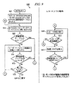
次に図9を参照すると、図示されるのは、受信電子メッセージを管理するのに用いるために接続マネジャ322により採用される手順の一実施形態を説明する流れ図900である。より詳細には、図900は、送信IPアドレスと、EMS203により管理された組織的階層における特定の受信者の構成パラメータに基づいて、制御命令を割り当てることを説明するものである。MPS426がトラフィックストリームにおける新しい受信者を識別する新しい「RCPT」コマンドを検出するたびに、MPS426により接続マネジャ322の動作が開始される。接続マネジャ322の最初の動作条件が、図900のステップ902に示されている。ステップ904において、接続マネジャ322が新しい受信者に対応するIIDをもつレコードについて接続管理テーブル370に問い合わせする。判断ブロック906において、接続管理テーブル370が特定のIIDについてのエントリを含んでいることが判断された場合には、制御は、第2の制御ループに送られ、そこで各IIDレコードが読み出され(ステップ908)、それが依然としてアクティブであるか又は有効期限切れであるかどうかを確かめるために試験され(ステップ910)、それに対して動作する(ステップ912)。単一のIIDは、複数のレコードをもってもよく、そのため、上記のステップ908−912におけるアクションは、判断ブロック914で反映されるようにIIDについての付加的なレコードが存在する限り、図900に示されるように繰り返される。
Referring now to FIG. 9, illustrated is a
図9に示すように、特定の受信者は階層内の一定のレベルに適合することができ、この方法においては、これらの階層レベルの各々に従って特定の接続アクションを調整することができる。したがって、ステップ916において、特定のIIDが、次の上位の階層レベルにおけるメンバーシップについて試験される。接続マネジャ322がこの階層レベルに特定のIIDに関連付けられた接続管理テーブルにおけるレコードが存在すると知った場合には、判断ステップ918のプロセスの流れにより、より上位のレベルにおいてIIDと関連付けられたアクションの全てについて、ステップ908−914のループのアクションが繰り返される。既に述べたように、この階層レベルにおける所与のIIDに関連する全てのアクションが実行され、制御が判断ステップ920に戻るとすぐに、階層の最上位レベルに到達したかどうかを確認するために、そのIIDが該階層レベルに対して試験される。最高の階層レベルに到達した場合には、接続マネジャ322は制御をMPS426に戻す。
As shown in FIG. 9, a particular recipient can adapt to a certain level in the hierarchy, and in this way, specific connection actions can be adjusted according to each of these hierarchy levels. Thus, at
接続は、一対のエンドポイント、すなわち送信者及び受信者として特徴付けることができる。接続は、送信者/受信者の対に基づいて管理することができ、又は受信者の識別子のみに基づいて管理されてもよい。IPアドレス範囲は、不確定位置に応じて、送信者及び/又は受信者を特定するのに用いることができ、範囲又は不確定性はまた、特定のIPアドレスが階層内のどこに所属するかを特定するのに用いることができる。一定のIPアドレス範囲により定められる組におけるIPアドレスのメンバーシップを、そのアドレスの階層組織メンバーシップを定義するのに用いることもできる。
接続管理レコードは、階層内の組織ごとの基準に基づいて挿入することができ、それらは、上位レベルの組織から下方の下位レベルの組織まで継承することができる。図9のプロセスの流れに関して説明したように、レコードは、特定の組織から底辺の組織までボトムアップ形式で処理することができる。単一の組織に複数のレコードが存在するとき、それらは、最も近い日に期限が切れるものを最初に試験するというように、有効期限順に処理しても良い。或いは、それらは、プロセスがどのように定義されるかに応じて、異なる順序で処理されてもよい。
A connection can be characterized as a pair of endpoints, a sender and a receiver. Connections can be managed based on sender / recipient pairs, or may be managed based only on recipient identifiers. IP address ranges can be used to identify senders and / or recipients, depending on the uncertainty location, and ranges or uncertainty can also indicate where a particular IP address belongs in the hierarchy. Can be used to identify. Membership of an IP address in a set defined by a certain IP address range can also be used to define the hierarchical organization membership of that address.
Connection management records can be inserted based on criteria for each organization in the hierarchy, and they can be inherited from higher level organizations to lower level organizations. As described with respect to the process flow of FIG. 9, records can be processed in a bottom-up fashion from a particular organization to the underlying organization. When there are multiple records in a single organization, they may be processed in order of expiration, such that the ones that expire on the closest day are tested first. Alternatively, they may be processed in a different order depending on how the process is defined.
前述のように、要求された接続に基づいてとることができる多くの形式のアクション又は処置が存在するが、一般的なものの1つは、以下の事象、すなわち、
・エラー:エラーメッセージが指定され、送信者に返送されること(例えば「Error501−unknown user」
・検疫:規定の理由(例えば、わいせつ、ポルノ又はウィルス感染)の下でメッセージが検疫されること。
・ブラックホール:メッセージが配信されるように見える(すなわち、配信確認が送信者に送られる)が、実際にはどこへも行かないこと。さらなる修正が行われない限り、別のアプリケーションがメッセージを検疫させることもある。
・受諾:メッセージが受諾され、宛先サーバに転送されること。さらなる修正が行われない限り、別のアプリケーションがメッセージを遮断することもある。
・スプール:IIDに対応するEメールサーバが応答せず、それによりメッセージがスプーラに書き込まれること。
前述のように、接続マネジャ322は、電子メッセージ・トランザクションにおける要求された接続の受諾及び実行を取り扱う。前述の措置は、接続マネジャ322が管理コンソール316を通じた手動構成によって実施することができ、又はそれらは、インタープリタ・プロセス350か又は別のソフトウェアモジュールによって自動的に実施されてもよい。図8のプロセスと同様に、図9に示されたプロセスの実施は、ここで説明された特定のステップに限定されるものではない。したがって、より多くの又はより少ない数のステップを採用することができる。さらに、図9に示されたものより多くの又はより少ない詳細を有するステップを有利に用いることもできる。
As mentioned above, there are many types of actions or actions that can be taken based on the requested connection, but one common one is the following event:
Error: An error message is specified and returned to the sender (for example, “Error501-unknown user”)
• Quarantine: A message is quarantined for a specified reason (eg, obscene, pornographic or viral infection).
Black hole: The message appears to be delivered (ie a delivery confirmation is sent to the sender) but does not actually go anywhere. Another application may quarantine the message unless further modifications are made.
Accept: The message is accepted and forwarded to the destination server. Another application may block the message unless further modifications are made.
Spool: The e-mail server corresponding to the IID does not respond, thereby writing a message to the spooler.
As described above, the
次に図10を参照すると、図示されているのは、図3−図4に伴う本文においても概略的に説明されたインタープリタ・プロセス350の作動流れ図1000である。インタープリタ・プロセス350のプロセスフローの実行はステップ1002で始まり、それはプロセスのスリープ状態である。一定時間後に、例えば15秒後に、プログラムフローの実行がステップ1004に移行する。ステップ1004において、EMS203が応答できる全ての組織についてのEMS203の構成がアップデートされる。このプロセスは、「同期」と呼ぶこともできる。ステップ1006において、インタープリタ・プロセス350が、ステップ1004で識別された各組織について生起するトラフィック・イベントを解析し始める。このアクションの一部として、EMS203は、トラフィックモニタ340に格納されたデータに反映された際に生起するトラフィック・イベントを評価する。
Referring now to FIG. 10, illustrated is an operational flow diagram 1000 of the
プロセスフローがステップ1010に続き、そこでEMS203が、考慮中の組織についての特定のEMS203イベントルールのイベント状態を評価する。判断ステップ1012において、インタープリタ・プロセス350のソフトウェアが、特定のルールがアクティブなものであるかどうかを問い合わせる。ルールがアクティブではない場合には、プロセスフローは判断ステップ104に進み、そこでソフトウェアモジュールが、特定の組織について処理されるべきEMS203イベントルールがさらに存在するかどうかを問い合わせる。特定の組織についてのEMS203イベントルールがそれ以上存在しない場合には、プロセスフローが判断ステップ1016に進み、そこでソフトウェアモジュールが、EMS203イベントが処理されるべき付加的なEMS203組織が存在するかどうかを問い合わせる。処理されるべき付加的なEMS203組織が存在しない場合には、ステップ1002においてソフトウェアモジュールが動作をこのプロセスフローの始まりであったスリープモードに戻す。しかしながら、処理されるべきEMS203イベントルールを有する付加的なEMS203組織が存在する場合には、動作がステップ1006に戻り、そこでソフトウェアモジュールが、再びこの他の組織についてのEMS203イベントルールに対してEMS203トラフィックを評価するプロセスを開始することになる。
The process flow continues to step 1010 where the
再びステップ1010において、各EMS203イベントルールに対してイベント状態が評価される。このケースでは、判断ステップ1012においてルールがアクティブである場合には、ソフトウェアフローがステップ1020に進むことになる。ステップ1020において、インタープリタ・プロセス350が、各トラフィック・セルを評価し、トラフィック・セルは発信元と宛先との間の単一接続であり、データテーブル504における単一セルによりトラフィックモニタ340において表わされる。判断ステップ1022において、ステップ1020における特定のトラフィック・セルの肯定的評価結果が正(「1より大きい結果」)である場合には、インタープリタ・プロセス350のアルゴリズムが判断ステップ1024に続く。判断ステップ1024において、既にトリガされているかどうかを確認するために、ルール・ステートが評価される。トリガされていない場合には、ステップ1026において、イベント実行が開始される。ルール・ステートが既にトリガされている場合には、イベントの実行がステップ1028に続くことになる。いずれの場合においても、動作がステップ1030に続き、その時点で、特定のイベント・ステータスに関連付けられたアクションを「ファイアリング」するためにプロセスが開始される。
Again in step 1010, the event state is evaluated for each
判断ステップ1032において、インタープリタ・プロセス350が、そのイベントに関連付けられた特定のアクションが、プロセス実行においてそれに関連付けられたステートを既にもつかどうかを問い合わせる。もっていなければ、インタープリタ・プロセス350が、判断ステップ1034において特定のアクションを遅延すべきかどうかを問い合わせる。アクションが遅延されるべきではない場合には、ステップ1036において、特定のアクションが「ファイア」され、そのアクションの開始を示すステートが設定される。次に、判断ステップ1038において、インタープリタ・プロセス350が、ファイアされるべき付加的なアクションが存在するかどうかを問い合わせる。存在する場合には、実行がステップ1030に戻り、このループにおいて、特定のイベントに関連する全てのアクションが処理されるまで、ステップ1030からステップ1039までが続く。ステップ1038において「ファイア」されるべきアクションがそれ以上存在しない場合には、実行が判断ステップ1040に進み、そのときインタープリタ・プロセス350ソフトウェアが、評価されるべきトラフィックがそれ以上存在するかどうかを試験する。評価されるべき付加的なトラフィック・セルが存在しない場合には、プロセスがステップ1020に戻る。評価されるべきトラフィック・セルがそれ以上存在しない場合には、プロセスが判断ステップ1014に戻り、そこで、処理されるべき付加的なEMS203ルールが存在するかどうか判断される。この判断に基づき、プロセスは、既に説明したステップ1010か又はステップ1016に続くことができる。
In
ステップ1020においてトラフィック・セルを再び評価し、判断ステップ1022において正の結果が存在しない場合には、プロセスがステップ1050に進み、そこでインタープリタ・プロセス350が、特定のルール・ステートが既にONであったかどうかを問い合わせる。ONでなかった場合には、このルール・ステートに関してとられる特定のアクションが存在せず、トラフィック・セルの処理を判断ステップ1040に続けることができる。しかしながら、ルール・ステートが前はONであったが今はOFFである場合には、それは、判断ステップ1050における正の結果によって示される状態であり、プロセスはステップ1052に進んで、その特定のルール・ステートの終了プロシージャを評価する。判断ステップ1054において正の結果が生じる場合には、ステップ1056において特定のルール・ステートのイベントエンドが処理される。しかしながら、判断ステップ1054における負の結果により示されるように、実行されるべきエンドプロセスが存在しない場合には、インタープリタ・プロセス350のアルゴリズムが、判断ステップ1040及びその後の分岐を通して付加的なトラフィック・セルを処理し続ける。
If the traffic cell is re-evaluated at step 1020 and there is no positive result at
次に図11を参照すると、図示されているのは、トラフィックモニタ340におけるトラフィックのリアルタイムでの監視のためのEMS203の実施形態において用いることができるデータ構造である。図5に示されていたように、或る実施形態においては、複数のメッセージ取扱いコンピュータ処理320a、320bが用いられ、それにより単一のトラフィックモニタ340及びインタープリタ・プロセス350への複数の接続が、平行して処理される。図11は、単一リングバッファ1102に接続される複数のこうしたコンピュータ処理320a、320bのMPS426a−426dを示し、それは、最終的に、この実施形態においては単一トラフィックモニタにデータを与える。MPS426a−426dは、それらのデータを、小さな非同期式データブロックの形態でリングバッファ1102に送信する。データは、各インスタンスにおける時間及びセッションIDによりタグ付けされる。例えば、各データブロックは、ヘッダ「SID8,00:02」によりタグ付けされ、それは、セッションIDがセッションナンバー8であり、データの受信時間が00:02であることを示す。この例で示されるセッションID及び時間は単なる例であり、百又は千となるセッションIDを用いることができる。さらに、1000分の1秒又はそれ以下の厳密な時間表示を用いることもできる。
Referring now to FIG. 11, illustrated is a data structure that can be used in an embodiment of
リングバッファ1102は、接続マネジャ322、配信マネジャ324、MPS426a−426dにより生成された全てのデータを保持し、この例においては、データをSID順にソートし、それは後の中間フォーマットに挿入する際の検索オーバーヘッドを減少させ、データをリングバッファ1102の中にソーティングするときの効率を与えることもできる。リングバッファ1102から、トラフィック監視データが中間データ構造1110に格納される。この中間データ構造1110においては、データがセッションIDに関連付けられたグループ1120に入れられ、グループ1120は、各接続(C1、C2...CN)、及び各接続により送信された各メッセージ(M1、M2、M3...)についてのレコードを有する。このデータは、リングバッファ1102からの新しいデータにより継続的にアップデートされ、データが現在のトラフィックモニタ・データ・マトリックス1130に格納されたデータより古いときに継続的にリフレッシュされる。
The
データ・マトリックス1130の構造は、トラフィックモニタ・データマトリックス1130の単なる例示的なフォーマットであり、インタープリタ・プロセス350によるアクセスのために維持される。中間データ構造1110の使用により、よりコンパクトなトラフィックモニタ・データマトリックス1130が可能とされ、空のセルをもたないように構造化することができる。データ・マトリックス1130は、異なるIID(宛先)が異なる行に分布し、異なる発信元IP(SIP又は発信元)が各行内の異なる列として分布するように配置される。SIPについての独立した列エントリを有するように各行を個々に構造化することにより、図11に示すように、空のセルなしに、このデータテーブル又はマトリックス1130を構築することができる。次いで、各セル内に、異なる統計値を与えることができ、インタープリタ・プロセス350は、これらのセルに格納された情報に基づいて、一定のアクティビティを認識することができる。
The structure of the data matrix 1130 is merely an example format for the traffic monitor data matrix 1130 and is maintained for access by the
インタープリタ・プロセス350と他のリソースとの両方が、トラフィックモニタ・データ・マトリックス1130へのアクセスを有することが望ましい。データ・マトリックス1130のコンテンツへのアクセスを可能にするために、少なくとも2つの異なる機構、すなわちダイレクト及びプールを与えることができる。ダイレクトアクセスを通して、インタープリタ・プロセス350は、データ・マトリックス1130の所与のセルをロックして、そのセルのデータをリアルタイムで読み出すことができる。プールされたアクセスを通じて、プロセスは、ネットワークを介するデータ・マトリックス1130のデータへのアクセスを要求するための複数のリソースを与える。データ・マトリックス1130又はデータ・マトリックス1130に関連するプロセスは、要求を仲裁することができ、データ・マトリックス1130における要求されたデータを一定の周期でロックし、そのデータにアクセスし、要求するリソースに送信することができる。データは、生データ、合計データとして要求することができ、又は顧客のメールホストによって要求されても良い。
It is desirable that both the
したがって、ここで説明されたシステムは、全ての受信要求及び要求された宛先、全ての関連するメッセージパラメータ(スパム、ウィルス、受信者、接続時間、データサイズ、宛先サーバのリターンコード等)をデータ・マトリックスにリアルタイムでマッピングするとともに、あらゆる数の受信者Eメールアドレス又は多数の顧客にわたるメールサーバについての接続/宛先マトリックスをリアルタイムで監視し、トラフィックモニタ・データ・マトリックス1130のステートのリアルタイムでの監視に基づき、アクションを直ちに自動的に開始する機能を有する。説明された実施形態が所有する他のシステムの機能には、必ずしも単一のサーバだけではない受信者メールシステムへの接続を要求するために生じた全てのSMTP接続をリアルタイムで認識する機能を含む。説明されたEMSはまた、1顧客/受信者からのマトリックスデータを用いて、別の顧客/受信者についてのアクションを修正することができる。例えば、EMSが1つの顧客グループに向けられたそのアクションに基づいて「スパム発信者」を認識する場合には、EMSはまた、その発信元からのスパムが他の宛先に到達するのを防止することができる。
したがって、ここで説明されるEMSは、多くの受信接続を取り扱い、フィルタリングし、監視し、反応することができる。しかしながら、EMSはまた、そのサーバにおけるローディング又は他の状態に基づいて、メッセージの配信を宛先メールサーバに合わせるように動作可能である。多数の宛先サーバ間で負荷のバランスをとり、宛先サーバに発信されるメッセージを制御された形でスプールし、異なる条件に基づいて宛先サーバにメッセージを条件付で配信することができる。
Thus, the system described here will receive all incoming requests and requested destinations, all relevant message parameters (spam, viruses, recipients, connection time, data size, destination server return code, etc.) Map to matrix in real time and monitor connection / destination matrix for any number of recipient email addresses or mail servers across multiple customers in real time, for real-time monitoring of traffic monitor data matrix 1130 state Based on this, it has a function to automatically start an action immediately. Other system functions possessed by the described embodiments include the ability to recognize in real time all SMTP connections that occur to request connections to a recipient mail system, not necessarily just a single server. . The described EMS can also use matrix data from one customer / recipient to modify the action for another customer / recipient. For example, if the EMS recognizes a “spam sender” based on its actions directed to one customer group, the EMS also prevents spam from that source from reaching other destinations. be able to.
Thus, the EMS described herein can handle, filter, monitor, and react to many incoming connections. However, the EMS is also operable to tailor message delivery to the destination mail server based on loading or other conditions at that server. It is possible to balance the load among a large number of destination servers, spool messages sent to the destination servers in a controlled manner, and conditionally distribute the messages to the destination servers based on different conditions.
次に図12を参照すると、図示されているのは、後述するように3つのMPSを含むスプール・マネジャである。スプール配信マネジャは、EMSのメッセージ取扱いコンピュータ処理で動くMPSプラグインにより呼び出され、接続マネジャと調和して作動して、メッセージがスプールされるべきかどうかを判断する。図12を参照すると、スプール配信マネジャは、以下のように機能する。
1)組織メールサーバが到達不能であることを検出した場合には、スプール(SPOOL)を開始するために、SPOOL接続管理レコードを、UIを通じて手動で又はインタープリタ・プロセスにより自動的に、組織について挿入しなければならない。
2)接続マネジャが、接続管理テーブルにSPOOL接続管理レコードが存在する組織に送信される各メッセージに、SPOOLタグを割り当てる。
3)スプール配信マネジャが、各受信メッセージを「スプール」タグについて試験する。
4)メッセージにスプールタグが存在する場合には、スプール配信マネジャは、メッセージが配信されるのを遮断し、その代わりにスプーラを用いてスプールサーバへのメッセージを遅延する。
Referring now to FIG. 12, illustrated is a spool manager that includes three MPSs as described below. The spool delivery manager is called by an EMS message handling computer process-run MPS plug-in and works in conjunction with the connection manager to determine if a message should be spooled. Referring to FIG. 12, the spool delivery manager functions as follows.
1) If the organization mail server detects that it is unreachable, a SPOOL connection management record is inserted into the organization, either manually through the UI or automatically by the interpreter process, to initiate spooling (SPOOL) Must.
2) The connection manager assigns a SPOOL tag to each message transmitted to an organization having a SPOOL connection management record in the connection management table.
3) The spool delivery manager tests each received message for a “spool” tag.
4) If a spool tag is present in the message, the spool delivery manager blocks the message from being delivered and instead uses a spooler to delay the message to the spool server.
スプーラは、スプールサーバ上で動作する修正されたMPSアプリケーションであり、スプール配信マネジャからのメッセージを受諾し、それらをスプール・リポジトリに格納する。図12を参照すると、スプーラは、以下のように機能する。
1)スプーラは、スプール配信マネジャからのSMTP接続要求を待つ。
2)メッセージ生データを含む受信SMTPコマンドの各々が、組織の(すなわち受信者の)スプール・リポジトリに格納される。
3)スプールサイズが、幾つかの所定のスプールサイズ・チェックポイントの1つ(例えば容量の75%)に到達した場合には、警告通知が生成される。
4)メッセージを格納した後に、スプールサイズが組織についての最大割当てスプールサイズを超えた場合には、警告通知が生成され、スプール接続管理レコードが除去されて、その後のメッセージをスプールするのが防止される。
5)メッセージにスプールタグが存在する場合には、スプール配信マネジャは、メッセージが配信されるのを遮断し、その代わりにSMTP接続を用いてスプールサーバへのメッセージを遅延する。
A spooler is a modified MPS application that runs on a spool server and accepts messages from the spool delivery manager and stores them in a spool repository. Referring to FIG. 12, the spooler functions as follows.
1) The spooler waits for an SMTP connection request from the spool distribution manager.
2) Each of the received SMTP commands including raw message data is stored in the organization's (ie, recipient's) spool repository.
3) A warning notification is generated if the spool size reaches one of several predetermined spool size checkpoints (eg, 75% of capacity).
4) After storing a message, if the spool size exceeds the maximum allocated spool size for the organization, a warning notification is generated and the spool connection management record is removed, preventing subsequent messages from being spooled. The
5) If a spool tag is present in the message, the spool delivery manager blocks the message from being delivered and instead delays the message to the spool server using an SMTP connection.
デスプーラもまた、スプールサーバ上で動作する修正されたMPSアプリケーションであり、スプール配信マネジャからのメッセージを受諾し、それらをスプール・リポジトリに保存する。この目的のために、デスプーラは、以下のように機能する。
1)デスプーラは、スプール配信マネジャからのSMTP接続要求を待つ。
2)メッセージ生データを含む受信SMTPコマンドの各々が、トラフィックモニタに格納される。
3)スプール配信マネジャは、適正な接続を維持するために、組織への接続を制限する。
4)メッセージが組織によって拒否された場合には、デスプーラがメッセージを元の送信者に返送する。
5)メッセージが上手く配信された場合には、スプール・リポジトリにおいて「配信済み」タグが付される。
ステップ2−5は、スプール・リポジトリにおける全てのメッセージが配信されるまで繰り返される。
The despooler is also a modified MPS application that runs on the spool server, accepting messages from the spool delivery manager and storing them in the spool repository. For this purpose, the despooler functions as follows.
1) The despooler waits for an SMTP connection request from the spool delivery manager.
2) Each received SMTP command including raw message data is stored in the traffic monitor.
3) The spool delivery manager restricts the connection to the organization in order to maintain a proper connection.
4) If the message is rejected by the organization, the despooler returns the message to the original sender.
5) If the message is successfully delivered, a “delivered” tag is added in the spool repository.
Steps 2-5 are repeated until all messages in the spool repository have been delivered.
次に図13を参照すると、図示されているのは、本発明に係るEMSと共に用いられる管理コンソールのアクセスページの一例のスクリーンショット1300である。図示のように、アクセスページは、ユーザ及び/又はシステム管理者が、彼らの電子メッセージネットワークにおいて生起する統計及び警告を監視するのに利用可能である。さらに、アクセスページは、電子メッセージの伝送を管理するためにEMSによって用いられるルールを構成するために、ユーザ及び/又はシステム管理者によって用いられても良い。ここで示される特定のアクセスページは、「Connection Mgr」「Delivery Mgr」、「Spool Mgr」、「Alerts」及び「Reports」を含む多数のアクセスタブを含む。EMSのこれらの個々のコンポーネントにアクセスすることに加えて、図13におけるアクセスページは、個々のコンポーネントのステータスを与えるとともに、システムへの電子メッセージの流れの概観を与える。
Referring now to FIG. 13, illustrated is a
次に簡単に図14を参照すると、図示されているのは、本発明に係るEMSに用いられる接続マネジャを監視し、構成するためのページの一例のスクリーンショット1400である。図示のように、このアクセスページは、EMSにおける接続マネジャのステータスを表示するとともに、発生した特定の伝送違反の統計を与える。説明された特定の害を与えるアクティビティは、ディレクトリ獲得攻撃、ウィルスの大発生、Eメール爆弾、及びスパム攻撃のみであるが、アクセスページは、限定なしに、他の形式の害を与える挙動の統計を説明するように構成されてもよい。
図15は、本発明のEMSに用いられる接続マネジャの別のアクセスページの例のスクリーンショット1500である。図示のように、このアクセスページは、受信電子メッセージの特定の害を与えるアクションの定義を与え、必要性が生じたときにユーザがEMSを構成するのを支援する。さらに、このアクセスページはまた、ユーザが彼らの受信電子メッセージを管理するための幅広い範囲の選択を可能にする種々の検出及び予防選択を含む。
Referring now briefly to FIG. 14, illustrated is a
FIG. 15 is a
図16を参照すると、図示されているのは、本発明に係るEMSに用いられる配信マネジャを監視し、構成するためのページの一例のスクリーンショット1600である。このアクセスページは、EMSにおける配信マネジャのステータスを表示するとともに、受信メッセージの害を与えるアクティビティに応答してEMSによりとられた特定の配信(又は非配信)アクションの統計を与える。さらに、このアクセスページは、ユーザが個別の宛先サーバのステータスを監視して、例えば、こうした宛先サーバの空き容量を判断できるようにする。
最後に、図17を参照すると、図示されているのは、EMSにおいて用いられる配信マネジャのためのページの別の例のスクリーンショットである。図示のように、このアクセスページは、ユーザが、図16に示された個々の宛先サーバの特定の詳細を構成できるようにする。このアクセスページを通じて変更できる構成パラメータは接続容量を含み、また、本発明により与えられる保護を享受する新たな宛先サーバをEMSに加えることができる。
ここで開示された原理に従って構成されたEMSの種々の実施形態、並びにEMSの特定のコンポーネントが上記で説明されたが、それらは単なる例として与えられたものであって、限定するためのものではないことを理解されたい。したがって、本発明の広さ及び範囲は、上述の例示的実施形態のいずれによっても限定されるべきではないが、特許請求の範囲の請求項及びそれらの均等物に従ってのみ定められるべきである。
Referring to FIG. 16, illustrated is a
Finally, referring to FIG. 17, illustrated is a screen shot of another example of a page for a distribution manager used in EMS. As shown, this access page allows the user to configure specific details of the individual destination server shown in FIG. The configuration parameters that can be changed through this access page include connection capacity, and new destination servers that enjoy the protection afforded by the present invention can be added to the EMS.
While various embodiments of EMS constructed in accordance with the principles disclosed herein, as well as specific components of EMS, have been described above, they are given by way of example only and are not intended to be limiting. I want you to understand. Accordingly, the breadth and scope of the present invention should not be limited by any of the above-described exemplary embodiments, but should be defined only in accordance with the following claims and their equivalents.
Claims (22)
複数の以前の受信電子メッセージに関する前記発信元データ及び前記宛先データを格納するデータ・マトリックス、及び前記データ・マトリックスにアクセスするインターフェースを有するトラフィックモニタと、
前記複数の以前の受信電子メッセージから外挿されたメタデータであって、当該電子メッセージが送信メールサーバによって送信された後、意図した受信メールサーバ若しくは当該受信メールサーバを有するネットワークに対する任意のゲートウェイで受信される前に外挿されるメタデータを、前記発信元データ及び前記宛先データに追加するように構成され、且つ前記インターフェースに結合された、メッセージ取扱いプロセスと、
前記発信元データ及び前記宛先データ並びに前記メタデータにアクセスし、疑わしいメッセージソースを識別するためにメッセージソースに関するメッセージトラフィックパターンを特定し、且つそれらに基づく処理命令を生成するように構成され、前記インターフェースに結合された、インタープリタ・プロセスと、
を含み、
前記メッセージ取扱いプロセスがさらに、階層構造に編成された受信電子メッセージの受信者に対し、前記処理命令に基づき、識別された疑わしいメッセージソースから意図された受信メールサーバへ送信された1以上の追加の受信電子メッセージの伝送を、当該追加の受信電子メッセージが意図した受信メールサーバ若しくは当該受信メールサーバを有するネットワークに対する任意のゲートウェイで受信される前にフィルタリングするとともに、前記受信電子メッセージの階層に属する他の受信メッセージ及び当該階層よりも上の階層の受信電子メッセージに対しても前記処理命令を適用するように構成されたことを特徴とするシステム。An electronic message management system used for managing transmission of an electronic message including transmission source data related to a transmission mail server and destination data related to a reception mail server from the transmission mail server to the reception mail server There,
A traffic monitor having a data matrix storing said source data and said destination data for a plurality of previously received electronic messages, and an interface accessing said data matrix;
Metadata extrapolated from the plurality of previous received electronic messages , after the electronic message is transmitted by a sending mail server, at an intended receiving mail server or any gateway to the network having the receiving mail server A message handling process configured to add metadata extrapolated before being received to the source data and the destination data and coupled to the interface;
The interface is configured to access the source data and the destination data and the metadata , identify message traffic patterns for message sources to identify suspicious message sources, and generate processing instructions based thereon An interpreter process coupled to
Including
The message handling process further includes one or more additional messages sent from the identified suspicious message source to the intended incoming mail server based on the processing instructions to recipients of the received electronic message organized in a hierarchical structure . the transmission of the received electronic message, as well as filtering before being received at any gateway to the network with a receiving mail server or the received mail server said additional received electronic message is intended, other belonging to the hierarchy of the received electronic message The system is configured to apply the processing instruction to a received message and a received electronic message in a layer higher than the received message .
メッセージ受諾、
メッセージ拒否、
メッセージ検疫、
メッセージスプール、
メッセージ据え置き、
メッセージ抑制、
メッセージ宛先変更、
接続拒否、
ブラックホール、
からなる群から選択される措置命令を生成するように構成されたことを特徴とする請求項2に記載の電子メッセージ管理システム。The interpreter process is
Message acceptance,
Message rejection,
Message quarantine,
Message spool,
Message deferred,
Message suppression,
Message destination change,
Connection refused,
Black Hole,
3. The electronic message management system according to claim 2 , wherein the electronic message management system is configured to generate a measure command selected from the group consisting of:
発信元IPアドレスからの接続試行のカウントと、
発信元IPアドレスからの現在開かれた接続のカウントと、
発信元IPアドレスからの接続継続時間と、
発信元IPアドレスからのメッセージのカウントと、
メッセージサイズと、
メッセージの受信者のカウントと、
発信元IPアドレスからのスパムメッセージのカウントと、
発信元IPアドレスからのウィルス感染メッセージのカウントと、
発信元IPアドレスからの望ましくないバイナリ添付を有するメッセージのカウントと、
発信元IPアドレスからの望ましくないコンテンツを有するメッセージのカウントと、 発信元IPアドレスからの、措置オプションが遮断され、ブラックホール化され、スプールされ又は検疫されたメッセージのカウントと、
宛先IPアドレスへの現在開かれた接続のカウントと、
宛先IPアドレスへの接続の継続時間と、
宛先IPアドレスへの失敗接続のカウントと、
宛先IPアドレスからの一時的据え置きエラーのカウントと、
宛先IPアドレスからの不明ユーザエラーのカウントと、
からなる群から選択されることを特徴とする請求項1に記載の電子メッセージ管理システム。Metadata extrapolated from the plurality of received electronic messages is:
A count of connection attempts from the source IP address;
A count of currently open connections from the source IP address;
Connection duration from the source IP address,
A count of messages from the source IP address;
Message size,
The message recipient count,
A count of spam messages from the source IP address,
Counting virus-infected messages from the source IP address;
A count of messages with undesirable binary attachments from the source IP address;
A count of messages with undesired content from the source IP address, and a count of messages from the source IP address where the action option is blocked, blackholed, spooled or quarantined;
A count of currently open connections to the destination IP address;
The duration of the connection to the destination IP address;
A count of failed connections to the destination IP address;
A temporary deferred error count from the destination IP address;
A count of unknown user errors from the destination IP address;
The electronic message management system according to claim 1 , wherein the electronic message management system is selected from the group consisting of:
複数の以前の受信電子メッセージの前記発信元データ及び前記宛先データをデータ・マトリックスに格納し、
前記複数の以前の電子メッセージが送信メールサーバによって送信された後、意図した受信メールサーバ若しくは当該受信メールサーバを有するネットワークに対する任意のゲートウェイで受信される前に、前記複数の以前の受信電子メッセージからメタデータを外挿し、
前記発信元データ及び前記宛先データに前記メタデータを追加し、
インターフェースを介して前記発信元データ及び前記宛先データ並びに前記メタデータにアクセスし、
前記発信元データ及び前記宛先データ並びに前記メタデータに基づいて、疑わしいメッセージソースを識別するためにメッセージソースに関するメッセージトラフィックパターンを特定し、
前記特定したメッセージトラフィックパターンに基づき処理命令を生成し、
階層構造に編成された受信電子メッセージの受信者に対し、前記処理命令に基づいて、識別された疑わしいメッセージソースから意図した受信メールサーバへ送信された1以上の追加の受信電子メッセージの伝送を、当該追加の受信電子メッセージが意図した受信メールサーバ若しくは当該受信メールサーバを有するネットワークに対する任意のゲートウェイで受信される前にフィルタリングするとともに、前記受信電子メッセージの階層に属する他の受信者及び当該階層よりも上の階層の受信電子メッセージに対しても前記処理命令を適用する、ことを含む方法。A method for managing transmission of an electronic message from a sending mail server to a receiving mail server, wherein the message sent from the sending mail server includes source data related to the sending mail server, and the receiving mail server And destination data related to
Storing the source data and the destination data of a plurality of previously received electronic messages in a data matrix;
After the plurality of previous electronic messages are sent by the outgoing mail server, before being received at the intended incoming mail server or any gateway for the network having the incoming mail server, from the plurality of previous incoming electronic messages Extrapolate metadata,
Adding the metadata to the source data and the destination data;
Accessing the source data and the destination data and the metadata via an interface;
Identifying message traffic patterns for message sources to identify suspicious message sources based on the source data and the destination data and the metadata ;
Generating a processing instruction based on the identified message traffic pattern ;
For the recipient of the received electronic message organized in a hierarchical structure, transmission of one or more additional received electronic messages sent from the identified suspicious message source to the intended incoming mail server based on the processing instructions ; Filtering before the additional received electronic message is received by the intended incoming mail server or any gateway for the network having the received mail server , and other recipients belonging to the received electronic message hierarchy and the hierarchy Applying the processing instructions also to received electronic messages at a higher hierarchy .
メッセージ受諾、
メッセージ拒否、
メッセージ検疫、
メッセージスプール、
メッセージ据え置き、
メッセージ抑制、
メッセージ宛先変更、
接続拒否、
ブラックホール、
からなる群から選択される措置命令を生成することを含む、請求項13に記載の方法。Generating the action instruction comprises:
Message acceptance,
Message rejection,
Message quarantine,
Message spool,
Message deferred,
Message suppression,
Message destination change,
Connection refused,
Black Hole,
14. The method of claim 13 , comprising generating an action instruction selected from the group consisting of:
発信元IPアドレスからの接続試行のカウントと、
発信元IPアドレスからの現在オープンな接続のカウントと、
発信元IPアドレスからの接続継続時間と、
発信元IPアドレスからのメッセージのカウントと、
メッセージサイズと、
メッセージの受信者のカウントと、
発信元IPアドレスからのスパムメッセージのカウントと、
発信元IPアドレスからのウィルス感染メッセージのカウントと、
発信元IPアドレスからの望ましくないバイナリ添付を有するメッセージのカウントと、
発信元IPアドレスからの望ましくないコンテンツを有するメッセージのカウントと、 発信元IPアドレスからの、措置オプションが遮断され、ブラックホール化され、スプールされ又は検疫されたメッセージのカウントと、
宛先IPアドレスへの現在オープンな接続のカウントと、
宛先IPアドレスへの接続の継続時間と、
宛先IPアドレスへの失敗接続のカウントと、
宛先IPアドレスからの一時的据え置きエラーのカウントと、
宛先IPアドレスからの不明ユーザエラーのカウントと、
からなる群から選択されるメタデータを外挿することを含む、請求項12に記載の方法。The extrapolation is
A count of connection attempts from the source IP address;
A count of currently open connections from the source IP address;
Connection duration from the source IP address,
A count of messages from the source IP address;
Message size,
The message recipient count,
A count of spam messages from the source IP address,
Counting virus-infected messages from the source IP address;
A count of messages with undesirable binary attachments from the source IP address;
A count of messages with undesired content from the source IP address, and a count of messages from the source IP address where the action option is blocked, blackholed, spooled or quarantined;
A count of currently open connections to the destination IP address;
The duration of the connection to the destination IP address;
A count of failed connections to the destination IP address;
A temporary deferred error count from the destination IP address;
A count of unknown user errors from the destination IP address;
The method of claim 12 , comprising extrapolating metadata selected from the group consisting of:
Applications Claiming Priority (2)
| Application Number | Priority Date | Filing Date | Title |
|---|---|---|---|
| US35789302P | 2002-02-19 | 2002-02-19 | |
| PCT/US2003/004757 WO2003071390A2 (en) | 2002-02-19 | 2003-02-19 | E-mail management services |
Publications (3)
| Publication Number | Publication Date |
|---|---|
| JP2005518173A JP2005518173A (en) | 2005-06-16 |
| JP2005518173A5 JP2005518173A5 (en) | 2006-04-06 |
| JP4593926B2 true JP4593926B2 (en) | 2010-12-08 |
Family
ID=27757671
Family Applications (1)
| Application Number | Title | Priority Date | Filing Date |
|---|---|---|---|
| JP2003570219A Expired - Lifetime JP4593926B2 (en) | 2002-02-19 | 2003-02-19 | Email management service |
Country Status (10)
| Country | Link |
|---|---|
| US (5) | US6941348B2 (en) |
| EP (2) | EP2068516B1 (en) |
| JP (1) | JP4593926B2 (en) |
| KR (1) | KR100871581B1 (en) |
| CN (1) | CN1332333C (en) |
| AT (1) | ATE427608T1 (en) |
| AU (1) | AU2003215276B2 (en) |
| CA (1) | CA2476349C (en) |
| DE (1) | DE60326938D1 (en) |
| WO (1) | WO2003071390A2 (en) |
Families Citing this family (350)
| Publication number | Priority date | Publication date | Assignee | Title |
|---|---|---|---|---|
| US20040073617A1 (en) | 2000-06-19 | 2004-04-15 | Milliken Walter Clark | Hash-based systems and methods for detecting and preventing transmission of unwanted e-mail |
| US6650890B1 (en) * | 2000-09-29 | 2003-11-18 | Postini, Inc. | Value-added electronic messaging services and transparent implementation thereof using intermediate server |
| US20020111937A1 (en) * | 2001-01-29 | 2002-08-15 | Mark Wetherbee | Method and system for permissible internet direct marketing |
| US8219620B2 (en) | 2001-02-20 | 2012-07-10 | Mcafee, Inc. | Unwanted e-mail filtering system including voting feedback |
| US7743119B2 (en) * | 2001-08-07 | 2010-06-22 | Motorola, Inc. | System and method for mapping identification codes |
| US7962622B2 (en) | 2001-08-07 | 2011-06-14 | Motorola Mobility, Inc. | System and method for providing provisioning and upgrade services for a wireless device |
| US7596565B2 (en) * | 2001-08-07 | 2009-09-29 | Good Technology | System and method for maintaining wireless file folders at a wireless device |
| US7243163B1 (en) * | 2001-08-07 | 2007-07-10 | Good Technology, Inc. | System and method for full wireless synchronization of a data processing apparatus with a messaging system |
| JP3797937B2 (en) * | 2002-02-04 | 2006-07-19 | 株式会社日立製作所 | Network connection system, network connection method, and network connection device used therefor |
| EP2068516B1 (en) * | 2002-02-19 | 2018-09-05 | Google LLC | E-mail management services |
| US7694128B2 (en) | 2002-03-08 | 2010-04-06 | Mcafee, Inc. | Systems and methods for secure communication delivery |
| US7458098B2 (en) * | 2002-03-08 | 2008-11-25 | Secure Computing Corporation | Systems and methods for enhancing electronic communication security |
| US8132250B2 (en) | 2002-03-08 | 2012-03-06 | Mcafee, Inc. | Message profiling systems and methods |
| US8578480B2 (en) | 2002-03-08 | 2013-11-05 | Mcafee, Inc. | Systems and methods for identifying potentially malicious messages |
| US7903549B2 (en) * | 2002-03-08 | 2011-03-08 | Secure Computing Corporation | Content-based policy compliance systems and methods |
| US6941467B2 (en) * | 2002-03-08 | 2005-09-06 | Ciphertrust, Inc. | Systems and methods for adaptive message interrogation through multiple queues |
| US7870203B2 (en) * | 2002-03-08 | 2011-01-11 | Mcafee, Inc. | Methods and systems for exposing messaging reputation to an end user |
| US7124438B2 (en) * | 2002-03-08 | 2006-10-17 | Ciphertrust, Inc. | Systems and methods for anomaly detection in patterns of monitored communications |
| US7693947B2 (en) * | 2002-03-08 | 2010-04-06 | Mcafee, Inc. | Systems and methods for graphically displaying messaging traffic |
| US20060015942A1 (en) | 2002-03-08 | 2006-01-19 | Ciphertrust, Inc. | Systems and methods for classification of messaging entities |
| US20030172291A1 (en) * | 2002-03-08 | 2003-09-11 | Paul Judge | Systems and methods for automated whitelisting in monitored communications |
| US8561167B2 (en) | 2002-03-08 | 2013-10-15 | Mcafee, Inc. | Web reputation scoring |
| US7447799B2 (en) * | 2002-04-24 | 2008-11-04 | Good Technology, Inc. | System and method for automatically updating a wireless device |
| US20030217094A1 (en) * | 2002-05-17 | 2003-11-20 | Anthony Dean Andrews | Correlation framework |
| US20030225850A1 (en) * | 2002-05-28 | 2003-12-04 | Teague Alan H. | Message processing based on address patterns |
| GB2401280B (en) * | 2003-04-29 | 2006-02-08 | Hewlett Packard Development Co | Propagation of viruses through an information technology network |
| GB2391419A (en) | 2002-06-07 | 2004-02-04 | Hewlett Packard Co | Restricting the propagation of a virus within a network |
| US9813514B2 (en) | 2002-06-12 | 2017-11-07 | Good Technology Holdings Limited | Information repository system including a wireless device and related method |
| US7310660B1 (en) * | 2002-06-25 | 2007-12-18 | Engate Technology Corporation | Method for removing unsolicited e-mail messages |
| US8516034B1 (en) | 2002-07-08 | 2013-08-20 | Good Technology Software, Inc | System and method for modifying application behavior based on network bandwidth |
| US8396926B1 (en) | 2002-07-16 | 2013-03-12 | Sonicwall, Inc. | Message challenge response |
| US20040015719A1 (en) * | 2002-07-16 | 2004-01-22 | Dae-Hyung Lee | Intelligent security engine and intelligent and integrated security system using the same |
| US8924484B2 (en) * | 2002-07-16 | 2014-12-30 | Sonicwall, Inc. | Active e-mail filter with challenge-response |
| US7539726B1 (en) | 2002-07-16 | 2009-05-26 | Sonicwall, Inc. | Message testing |
| US7908330B2 (en) * | 2003-03-11 | 2011-03-15 | Sonicwall, Inc. | Message auditing |
| AU2003259742B2 (en) | 2002-08-09 | 2010-07-15 | Reflexion Networks, Inc. | System and method for controlling access to an electronic message recipient |
| US7673058B1 (en) | 2002-09-09 | 2010-03-02 | Engate Technology Corporation | Unsolicited message intercepting communications processor |
| US7490128B1 (en) | 2002-09-09 | 2009-02-10 | Engate Technology Corporation | Unsolicited message rejecting communications processor |
| US7716351B1 (en) | 2002-09-09 | 2010-05-11 | Engate Technology Corporation | Unsolicited message diverting communications processor |
| US8380791B1 (en) | 2002-12-13 | 2013-02-19 | Mcafee, Inc. | Anti-spam system, method, and computer program product |
| WO2004061698A1 (en) * | 2002-12-30 | 2004-07-22 | Activestate Corporation | Method and system for feature extraction from outgoing messages for use in categorization of incoming messages |
| US7219131B2 (en) * | 2003-01-16 | 2007-05-15 | Ironport Systems, Inc. | Electronic message delivery using an alternate source approach |
| JP4344922B2 (en) * | 2003-01-27 | 2009-10-14 | 富士ゼロックス株式会社 | Evaluation apparatus and method |
| US7958187B2 (en) * | 2003-02-19 | 2011-06-07 | Google Inc. | Systems and methods for managing directory harvest attacks via electronic messages |
| US20060265459A1 (en) * | 2003-02-19 | 2006-11-23 | Postini, Inc. | Systems and methods for managing the transmission of synchronous electronic messages |
| US8266215B2 (en) * | 2003-02-20 | 2012-09-11 | Sonicwall, Inc. | Using distinguishing properties to classify messages |
| US7299261B1 (en) | 2003-02-20 | 2007-11-20 | Mailfrontier, Inc. A Wholly Owned Subsidiary Of Sonicwall, Inc. | Message classification using a summary |
| US7406502B1 (en) | 2003-02-20 | 2008-07-29 | Sonicwall, Inc. | Method and system for classifying a message based on canonical equivalent of acceptable items included in the message |
| US7856477B2 (en) * | 2003-04-04 | 2010-12-21 | Yahoo! Inc. | Method and system for image verification to prevent messaging abuse |
| US7796515B2 (en) * | 2003-04-29 | 2010-09-14 | Hewlett-Packard Development Company, L.P. | Propagation of viruses through an information technology network |
| US7653698B2 (en) | 2003-05-29 | 2010-01-26 | Sonicwall, Inc. | Identifying e-mail messages from allowed senders |
| US7814542B1 (en) * | 2003-06-30 | 2010-10-12 | Cisco Technology, Inc. | Network connection detection and throttling |
| US7051077B2 (en) * | 2003-06-30 | 2006-05-23 | Mx Logic, Inc. | Fuzzy logic voting method and system for classifying e-mail using inputs from multiple spam classifiers |
| US20050010644A1 (en) * | 2003-07-07 | 2005-01-13 | Brown Scott T. | High performance electronic message delivery engine |
| US20050015626A1 (en) * | 2003-07-15 | 2005-01-20 | Chasin C. Scott | System and method for identifying and filtering junk e-mail messages or spam based on URL content |
| US7814545B2 (en) * | 2003-07-22 | 2010-10-12 | Sonicwall, Inc. | Message classification using classifiers |
| US7383306B2 (en) * | 2003-07-31 | 2008-06-03 | Hewlett-Packard Development Company, L.P. | System and method for selectively increasing message transaction costs |
| GB2405229B (en) * | 2003-08-19 | 2006-01-11 | Sophos Plc | Method and apparatus for filtering electronic mail |
| US7451487B2 (en) | 2003-09-08 | 2008-11-11 | Sonicwall, Inc. | Fraudulent message detection |
| US20050114457A1 (en) * | 2003-10-27 | 2005-05-26 | Meng-Fu Shih | Filtering device for eliminating unsolicited email |
| US7620690B1 (en) | 2003-11-20 | 2009-11-17 | Lashback, LLC | Privacy control system for electronic communication |
| US9401838B2 (en) * | 2003-12-03 | 2016-07-26 | Emc Corporation | Network event capture and retention system |
| US7647379B2 (en) * | 2003-12-19 | 2010-01-12 | International Business Machines Corporation | System and method for re-routing messaging traffic to external resources |
| US8886727B1 (en) | 2004-01-27 | 2014-11-11 | Sonicwall, Inc. | Message distribution control |
| US7970831B2 (en) * | 2004-02-02 | 2011-06-28 | The Boeing Company | Intelligent email services |
| US9471712B2 (en) | 2004-02-09 | 2016-10-18 | Dell Software Inc. | Approximate matching of strings for message filtering |
| US8856239B1 (en) | 2004-02-10 | 2014-10-07 | Sonicwall, Inc. | Message classification based on likelihood of spoofing |
| US7653695B2 (en) * | 2004-02-17 | 2010-01-26 | Ironport Systems, Inc. | Collecting, aggregating, and managing information relating to electronic messages |
| US8214438B2 (en) * | 2004-03-01 | 2012-07-03 | Microsoft Corporation | (More) advanced spam detection features |
| US20050216587A1 (en) * | 2004-03-25 | 2005-09-29 | International Business Machines Corporation | Establishing trust in an email client |
| US8898788B1 (en) | 2004-04-01 | 2014-11-25 | Fireeye, Inc. | Systems and methods for malware attack prevention |
| US8528086B1 (en) | 2004-04-01 | 2013-09-03 | Fireeye, Inc. | System and method of detecting computer worms |
| US8584239B2 (en) | 2004-04-01 | 2013-11-12 | Fireeye, Inc. | Virtual machine with dynamic data flow analysis |
| US8793787B2 (en) | 2004-04-01 | 2014-07-29 | Fireeye, Inc. | Detecting malicious network content using virtual environment components |
| US9106694B2 (en) | 2004-04-01 | 2015-08-11 | Fireeye, Inc. | Electronic message analysis for malware detection |
| US8566946B1 (en) | 2006-04-20 | 2013-10-22 | Fireeye, Inc. | Malware containment on connection |
| US7587537B1 (en) | 2007-11-30 | 2009-09-08 | Altera Corporation | Serializer-deserializer circuits formed from input-output circuit registers |
| US8171553B2 (en) | 2004-04-01 | 2012-05-01 | Fireeye, Inc. | Heuristic based capture with replay to virtual machine |
| US8549638B2 (en) | 2004-06-14 | 2013-10-01 | Fireeye, Inc. | System and method of containing computer worms |
| US8881282B1 (en) | 2004-04-01 | 2014-11-04 | Fireeye, Inc. | Systems and methods for malware attack detection and identification |
| US7640307B2 (en) * | 2004-04-19 | 2009-12-29 | Bigstring Corporation | Universal recallable, erasable, secure and timed delivery email |
| US7783706B1 (en) | 2004-04-21 | 2010-08-24 | Aristotle.Net, Inc. | Filtering and managing electronic mail |
| US7647321B2 (en) * | 2004-04-26 | 2010-01-12 | Google Inc. | System and method for filtering electronic messages using business heuristics |
| CA2733172C (en) * | 2004-05-07 | 2011-10-25 | Sandvine Incorporated Ulc | A system and method for detecting sources of abnormal computer network messages |
| US7912905B2 (en) * | 2004-05-18 | 2011-03-22 | Computer Associates Think, Inc. | System and method for filtering network messages |
| US7756929B1 (en) * | 2004-05-18 | 2010-07-13 | Microsoft Corporation | System and method for processing e-mail |
| US7668951B2 (en) * | 2004-05-25 | 2010-02-23 | Google Inc. | Electronic message source reputation information system |
| CN100573442C (en) * | 2004-05-25 | 2009-12-23 | 反射网络公司 | Be used to control system and method to the visit of electronic message recipient |
| US7698369B2 (en) | 2004-05-27 | 2010-04-13 | Strongmail Systems, Inc. | Email delivery system using metadata on emails to manage virtual storage |
| US7756930B2 (en) | 2004-05-28 | 2010-07-13 | Ironport Systems, Inc. | Techniques for determining the reputation of a message sender |
| US7917588B2 (en) * | 2004-05-29 | 2011-03-29 | Ironport Systems, Inc. | Managing delivery of electronic messages using bounce profiles |
| US7849142B2 (en) * | 2004-05-29 | 2010-12-07 | Ironport Systems, Inc. | Managing connections, messages, and directory harvest attacks at a server |
| US7870200B2 (en) * | 2004-05-29 | 2011-01-11 | Ironport Systems, Inc. | Monitoring the flow of messages received at a server |
| US7873695B2 (en) * | 2004-05-29 | 2011-01-18 | Ironport Systems, Inc. | Managing connections and messages at a server by associating different actions for both different senders and different recipients |
| US8166310B2 (en) | 2004-05-29 | 2012-04-24 | Ironport Systems, Inc. | Method and apparatus for providing temporary access to a network device |
| US20050289148A1 (en) * | 2004-06-10 | 2005-12-29 | Steven Dorner | Method and apparatus for detecting suspicious, deceptive, and dangerous links in electronic messages |
| US20060031318A1 (en) * | 2004-06-14 | 2006-02-09 | Gellens Randall C | Communicating information about the content of electronic messages to a server |
| US7748038B2 (en) * | 2004-06-16 | 2010-06-29 | Ironport Systems, Inc. | Method and apparatus for managing computer virus outbreaks |
| US8484295B2 (en) | 2004-12-21 | 2013-07-09 | Mcafee, Inc. | Subscriber reputation filtering method for analyzing subscriber activity and detecting account misuse |
| US7680890B1 (en) | 2004-06-22 | 2010-03-16 | Wei Lin | Fuzzy logic voting method and system for classifying e-mail using inputs from multiple spam classifiers |
| US7953814B1 (en) | 2005-02-28 | 2011-05-31 | Mcafee, Inc. | Stopping and remediating outbound messaging abuse |
| US7580981B1 (en) * | 2004-06-30 | 2009-08-25 | Google Inc. | System for determining email spam by delivery path |
| US7157327B2 (en) * | 2004-07-01 | 2007-01-02 | Infineon Technologies Ag | Void free, silicon filled trenches in semiconductors |
| US8671144B2 (en) * | 2004-07-02 | 2014-03-11 | Qualcomm Incorporated | Communicating information about the character of electronic messages to a client |
| US20060036690A1 (en) * | 2004-07-12 | 2006-02-16 | O'neil Patrick J | Network protection system |
| US9154511B1 (en) | 2004-07-13 | 2015-10-06 | Dell Software Inc. | Time zero detection of infectious messages |
| US7343624B1 (en) * | 2004-07-13 | 2008-03-11 | Sonicwall, Inc. | Managing infectious messages as identified by an attachment |
| US7634808B1 (en) * | 2004-08-20 | 2009-12-15 | Symantec Corporation | Method and apparatus to block fast-spreading computer worms that use DNS MX record queries |
| US20060047758A1 (en) * | 2004-08-26 | 2006-03-02 | Vivek Sharma | Extending and optimizing electronic messaging rules |
| US7552179B2 (en) * | 2004-09-20 | 2009-06-23 | Microsoft Corporation | Envelope e-mail journaling with best effort recipient updates |
| US7644126B2 (en) * | 2004-09-29 | 2010-01-05 | Qualcomm Incoporated | Message thread handling |
| US8495145B2 (en) * | 2004-10-14 | 2013-07-23 | Intel Corporation | Controlling receipt of undesired electronic mail |
| US8635690B2 (en) | 2004-11-05 | 2014-01-21 | Mcafee, Inc. | Reputation based message processing |
| US20060168013A1 (en) * | 2004-11-26 | 2006-07-27 | Invensys Systems, Inc. | Message management facility for an industrial process control environment |
| US8738708B2 (en) | 2004-12-21 | 2014-05-27 | Mcafee, Inc. | Bounce management in a trusted communication network |
| US9160755B2 (en) | 2004-12-21 | 2015-10-13 | Mcafee, Inc. | Trusted communication network |
| US9015472B1 (en) | 2005-03-10 | 2015-04-21 | Mcafee, Inc. | Marking electronic messages to indicate human origination |
| US20060168046A1 (en) * | 2005-01-11 | 2006-07-27 | Microsoft Corporaion | Managing periodic electronic messages |
| US7716743B2 (en) * | 2005-01-14 | 2010-05-11 | Microsoft Corporation | Privacy friendly malware quarantines |
| US7478132B2 (en) | 2005-01-24 | 2009-01-13 | International Business Machines Corporation | Dynamic email content update process |
| US8312119B2 (en) * | 2005-03-01 | 2012-11-13 | Microsoft Corporation | IP block activity feedback system |
| US10225282B2 (en) * | 2005-04-14 | 2019-03-05 | International Business Machines Corporation | System, method and program product to identify a distributed denial of service attack |
| US8583740B2 (en) * | 2005-04-25 | 2013-11-12 | Google Inc. | Actionable quarantine summary |
| US7854007B2 (en) * | 2005-05-05 | 2010-12-14 | Ironport Systems, Inc. | Identifying threats in electronic messages |
| US20060253597A1 (en) * | 2005-05-05 | 2006-11-09 | Mujica Technologies Inc. | E-mail system |
| US8874658B1 (en) * | 2005-05-11 | 2014-10-28 | Symantec Corporation | Method and apparatus for simulating end user responses to spam email messages |
| JP4559295B2 (en) * | 2005-05-17 | 2010-10-06 | 株式会社エヌ・ティ・ティ・ドコモ | Data communication system and data communication method |
| US7757288B1 (en) * | 2005-05-23 | 2010-07-13 | Symantec Corporation | Malicious e-mail attack inversion filter |
| US7937480B2 (en) | 2005-06-02 | 2011-05-03 | Mcafee, Inc. | Aggregation of reputation data |
| US20060277259A1 (en) * | 2005-06-07 | 2006-12-07 | Microsoft Corporation | Distributed sender reputations |
| US7552230B2 (en) * | 2005-06-15 | 2009-06-23 | International Business Machines Corporation | Method and apparatus for reducing spam on peer-to-peer networks |
| CA2518894C (en) * | 2005-06-23 | 2014-06-10 | Cognos Incorporated | Request routing system for and method of request routing |
| CA2510626A1 (en) * | 2005-06-23 | 2006-12-23 | Cognos Incorporated | Request routing system for and method of request routing |
| CN1921458B (en) * | 2005-08-23 | 2011-09-28 | 吴刚强 | System and method for uniform switch-in and exchange of enterprise E-mail |
| US20070061402A1 (en) * | 2005-09-15 | 2007-03-15 | Microsoft Corporation | Multipurpose internet mail extension (MIME) analysis |
| CN1794722B (en) * | 2005-09-19 | 2010-05-05 | 华为技术有限公司 | Method of transfering off-line message and instant message server |
| US7636944B2 (en) * | 2005-10-28 | 2009-12-22 | Hewlett-Packard Development Company, L.P. | Method and apparatus for detecting and responding to email based propagation of malicious software in a trusted network |
| US8077699B2 (en) * | 2005-11-07 | 2011-12-13 | Microsoft Corporation | Independent message stores and message transport agents |
| US8595814B2 (en) * | 2005-12-13 | 2013-11-26 | Google Inc. | TLS encryption in a managed e-mail service environment |
| US8601160B1 (en) | 2006-02-09 | 2013-12-03 | Mcafee, Inc. | System, method and computer program product for gathering information relating to electronic content utilizing a DNS server |
| US7620392B1 (en) | 2006-02-27 | 2009-11-17 | Good Technology, Inc. | Method and system for distributing and updating software in wireless devices |
| AU2013200872B2 (en) * | 2006-03-20 | 2014-08-21 | Google Inc. | Synchronous message management system |
| US20070220143A1 (en) * | 2006-03-20 | 2007-09-20 | Postini, Inc. | Synchronous message management system |
| WO2007109691A2 (en) * | 2006-03-20 | 2007-09-27 | Google Inc. | Synchronous message management system |
| US20070276915A1 (en) * | 2006-04-04 | 2007-11-29 | Wireless Services Corp. | Managing messages between multiple wireless carriers to multiple enterprises using a relatively limited number of identifiers |
| US8458261B1 (en) * | 2006-04-07 | 2013-06-04 | Trend Micro Incorporated | Determination of valid email addresses in a private computer network |
| US7958557B2 (en) * | 2006-05-17 | 2011-06-07 | Computer Associates Think, Inc. | Determining a source of malicious computer element in a computer network |
| US20080034375A1 (en) * | 2006-08-03 | 2008-02-07 | Ferrell Terry L | System and method to provide a message service agent with pluggable functionality |
| US20080052284A1 (en) * | 2006-08-05 | 2008-02-28 | Terry Stokes | System and Method for the Capture and Archival of Electronic Communications |
| US20080037583A1 (en) * | 2006-08-09 | 2008-02-14 | Postini, Inc. | Unified management policy for multiple format electronic communications |
| US8239943B2 (en) * | 2006-08-18 | 2012-08-07 | Microsoft Corporation | Network security page |
| US20080082658A1 (en) * | 2006-09-29 | 2008-04-03 | Wan-Yen Hsu | Spam control systems and methods |
| US8180835B1 (en) * | 2006-10-14 | 2012-05-15 | Engate Technology Corporation | System and method for protecting mail servers from mail flood attacks |
| US8583731B1 (en) | 2006-11-17 | 2013-11-12 | Open Invention Network Llc | System and method for analyzing and filtering journaled electronic mail |
| US20080126481A1 (en) * | 2006-11-26 | 2008-05-29 | Al Chakra | Method and system for providing communication context specific formality control |
| US20080133571A1 (en) * | 2006-12-05 | 2008-06-05 | International Business Machines Corporation | Modifying Behavior in Messaging Systems According to Organizational Hierarchy |
| US8286244B2 (en) * | 2007-01-19 | 2012-10-09 | Hewlett-Packard Development Company, L.P. | Method and system for protecting a computer network against packet floods |
| US7949716B2 (en) * | 2007-01-24 | 2011-05-24 | Mcafee, Inc. | Correlation and analysis of entity attributes |
| US7779156B2 (en) | 2007-01-24 | 2010-08-17 | Mcafee, Inc. | Reputation based load balancing |
| US8214497B2 (en) | 2007-01-24 | 2012-07-03 | Mcafee, Inc. | Multi-dimensional reputation scoring |
| US8179798B2 (en) | 2007-01-24 | 2012-05-15 | Mcafee, Inc. | Reputation based connection throttling |
| US8763114B2 (en) | 2007-01-24 | 2014-06-24 | Mcafee, Inc. | Detecting image spam |
| JP2008210203A (en) * | 2007-02-27 | 2008-09-11 | Digital Arts Inc | Electronic mail processing method and system |
| US9083712B2 (en) * | 2007-04-04 | 2015-07-14 | Sri International | Method and apparatus for generating highly predictive blacklists |
| CN101072202B (en) * | 2007-05-25 | 2012-03-21 | 腾讯科技(深圳)有限公司 | Electronic mail monitoring method and monitoring system |
| US7899870B2 (en) * | 2007-06-25 | 2011-03-01 | Microsoft Corporation | Determination of participation in a malicious software campaign |
| US8347286B2 (en) * | 2007-07-16 | 2013-01-01 | International Business Machines Corporation | Method, system and program product for managing download requests received to download files from a server |
| US8060569B2 (en) * | 2007-09-27 | 2011-11-15 | Microsoft Corporation | Dynamic email directory harvest attack detection and mitigation |
| US20090094334A1 (en) * | 2007-10-03 | 2009-04-09 | Anders Eriksson | Gateway with transparent mail relay |
| US8185930B2 (en) * | 2007-11-06 | 2012-05-22 | Mcafee, Inc. | Adjusting filter or classification control settings |
| US8045458B2 (en) | 2007-11-08 | 2011-10-25 | Mcafee, Inc. | Prioritizing network traffic |
| US20090138562A1 (en) * | 2007-11-28 | 2009-05-28 | Loyal Technology Solutions, L.L.C. | Method and system for aggregation of electronic messages |
| US20090182818A1 (en) * | 2008-01-11 | 2009-07-16 | Fortinet, Inc. A Delaware Corporation | Heuristic detection of probable misspelled addresses in electronic communications |
| US8160975B2 (en) | 2008-01-25 | 2012-04-17 | Mcafee, Inc. | Granular support vector machine with random granularity |
| EP2120493A1 (en) * | 2008-03-19 | 2009-11-18 | Nokia Siemens Networks Oy | Mechanism for automated re-configuration of an access network element |
| US8589503B2 (en) | 2008-04-04 | 2013-11-19 | Mcafee, Inc. | Prioritizing network traffic |
| US10354229B2 (en) * | 2008-08-04 | 2019-07-16 | Mcafee, Llc | Method and system for centralized contact management |
| US8789185B1 (en) * | 2008-09-15 | 2014-07-22 | Symantec Corporation | Method and apparatus for monitoring a computer system for malicious software |
| US8997219B2 (en) | 2008-11-03 | 2015-03-31 | Fireeye, Inc. | Systems and methods for detecting malicious PDF network content |
| US20100175103A1 (en) * | 2009-01-07 | 2010-07-08 | Microsoft Corporation | Reactive throttling of inbound messages and ranges |
| US8959157B2 (en) * | 2009-06-26 | 2015-02-17 | Microsoft Corporation | Real-time spam look-up system |
| KR101043003B1 (en) * | 2009-08-25 | 2011-06-21 | (주)이월리서치 | Zombie PC IP extraction method using a pattern for contents interception |
| US20110055264A1 (en) * | 2009-08-28 | 2011-03-03 | Microsoft Corporation | Data mining organization communications |
| US9529864B2 (en) * | 2009-08-28 | 2016-12-27 | Microsoft Technology Licensing, Llc | Data mining electronic communications |
| US8832829B2 (en) | 2009-09-30 | 2014-09-09 | Fireeye, Inc. | Network-based binary file extraction and analysis for malware detection |
| US8484512B2 (en) | 2010-03-31 | 2013-07-09 | Microsoft Corporation | Throttling non-delivery reports based on root cause |
| US8621638B2 (en) | 2010-05-14 | 2013-12-31 | Mcafee, Inc. | Systems and methods for classification of messaging entities |
| US20120066487A1 (en) * | 2010-09-09 | 2012-03-15 | Novell, Inc. | System and method for providing load balancer visibility in an intelligent workload management system |
| US8918467B2 (en) | 2010-10-01 | 2014-12-23 | Clover Leaf Environmental Solutions, Inc. | Generation and retrieval of report information |
| US8990316B1 (en) | 2010-11-05 | 2015-03-24 | Amazon Technologies, Inc. | Identifying message deliverability problems using grouped message characteristics |
| US8744979B2 (en) | 2010-12-06 | 2014-06-03 | Microsoft Corporation | Electronic communications triage using recipient's historical behavioral and feedback |
| CN102821002B (en) * | 2011-06-09 | 2015-08-26 | 中国移动通信集团河南有限公司信阳分公司 | Network flow abnormal detecting method and system |
| US8447851B1 (en) * | 2011-11-10 | 2013-05-21 | CopperEgg Corporation | System for monitoring elastic cloud-based computing systems as a service |
| US9231899B2 (en) * | 2012-01-13 | 2016-01-05 | International Business Machines Corporation | Transmittal of blocked message notification |
| US8995260B2 (en) | 2012-08-09 | 2015-03-31 | Blackberry Limited | Method and apparatus for managing load in a communication network |
| US8976648B2 (en) | 2012-08-09 | 2015-03-10 | Blackberry Limited | Method and apparatus for managing load on service devices in a communication network |
| US8918473B1 (en) * | 2012-10-09 | 2014-12-23 | Whatsapp Inc. | System and method for detecting unwanted content |
| US9654426B2 (en) | 2012-11-20 | 2017-05-16 | Dropbox, Inc. | System and method for organizing messages |
| US9935907B2 (en) | 2012-11-20 | 2018-04-03 | Dropbox, Inc. | System and method for serving a message client |
| US9729695B2 (en) | 2012-11-20 | 2017-08-08 | Dropbox Inc. | Messaging client application interface |
| US10572665B2 (en) | 2012-12-28 | 2020-02-25 | Fireeye, Inc. | System and method to create a number of breakpoints in a virtual machine via virtual machine trapping events |
| US9176843B1 (en) | 2013-02-23 | 2015-11-03 | Fireeye, Inc. | Framework for efficient security coverage of mobile software applications |
| US9195829B1 (en) | 2013-02-23 | 2015-11-24 | Fireeye, Inc. | User interface with real-time visual playback along with synchronous textual analysis log display and event/time index for anomalous behavior detection in applications |
| US9367681B1 (en) | 2013-02-23 | 2016-06-14 | Fireeye, Inc. | Framework for efficient security coverage of mobile software applications using symbolic execution to reach regions of interest within an application |
| US9626509B1 (en) | 2013-03-13 | 2017-04-18 | Fireeye, Inc. | Malicious content analysis with multi-version application support within single operating environment |
| US9355247B1 (en) | 2013-03-13 | 2016-05-31 | Fireeye, Inc. | File extraction from memory dump for malicious content analysis |
| US9104867B1 (en) | 2013-03-13 | 2015-08-11 | Fireeye, Inc. | Malicious content analysis using simulated user interaction without user involvement |
| US9430646B1 (en) | 2013-03-14 | 2016-08-30 | Fireeye, Inc. | Distributed systems and methods for automatically detecting unknown bots and botnets |
| US9311479B1 (en) | 2013-03-14 | 2016-04-12 | Fireeye, Inc. | Correlation and consolidation of analytic data for holistic view of a malware attack |
| US10713358B2 (en) | 2013-03-15 | 2020-07-14 | Fireeye, Inc. | System and method to extract and utilize disassembly features to classify software intent |
| US9413781B2 (en) | 2013-03-15 | 2016-08-09 | Fireeye, Inc. | System and method employing structured intelligence to verify and contain threats at endpoints |
| US9495180B2 (en) | 2013-05-10 | 2016-11-15 | Fireeye, Inc. | Optimized resource allocation for virtual machines within a malware content detection system |
| US9635039B1 (en) | 2013-05-13 | 2017-04-25 | Fireeye, Inc. | Classifying sets of malicious indicators for detecting command and control communications associated with malware |
| CN103281392A (en) * | 2013-06-07 | 2013-09-04 | 潍柴动力股份有限公司 | Method, device and system for monitoring |
| US10133863B2 (en) | 2013-06-24 | 2018-11-20 | Fireeye, Inc. | Zero-day discovery system |
| US9300686B2 (en) | 2013-06-28 | 2016-03-29 | Fireeye, Inc. | System and method for detecting malicious links in electronic messages |
| US10515214B1 (en) | 2013-09-30 | 2019-12-24 | Fireeye, Inc. | System and method for classifying malware within content created during analysis of a specimen |
| US9690936B1 (en) | 2013-09-30 | 2017-06-27 | Fireeye, Inc. | Multistage system and method for analyzing obfuscated content for malware |
| US9736179B2 (en) | 2013-09-30 | 2017-08-15 | Fireeye, Inc. | System, apparatus and method for using malware analysis results to drive adaptive instrumentation of virtual machines to improve exploit detection |
| US9294501B2 (en) | 2013-09-30 | 2016-03-22 | Fireeye, Inc. | Fuzzy hash of behavioral results |
| US9628507B2 (en) | 2013-09-30 | 2017-04-18 | Fireeye, Inc. | Advanced persistent threat (APT) detection center |
| US9171160B2 (en) | 2013-09-30 | 2015-10-27 | Fireeye, Inc. | Dynamically adaptive framework and method for classifying malware using intelligent static, emulation, and dynamic analyses |
| US9921978B1 (en) | 2013-11-08 | 2018-03-20 | Fireeye, Inc. | System and method for enhanced security of storage devices |
| US9756074B2 (en) | 2013-12-26 | 2017-09-05 | Fireeye, Inc. | System and method for IPS and VM-based detection of suspicious objects |
| US9747446B1 (en) | 2013-12-26 | 2017-08-29 | Fireeye, Inc. | System and method for run-time object classification |
| US9507935B2 (en) | 2014-01-16 | 2016-11-29 | Fireeye, Inc. | Exploit detection system with threat-aware microvisor |
| US9262635B2 (en) | 2014-02-05 | 2016-02-16 | Fireeye, Inc. | Detection efficacy of virtual machine-based analysis with application specific events |
| US9712483B1 (en) * | 2014-02-06 | 2017-07-18 | Sprint Communications Company L.P. | Automated check for simple mail transfer protocol email delays |
| US9584462B1 (en) | 2014-02-06 | 2017-02-28 | Sprint Communications Company L.P. | Universal email failure notification system |
| TWI511060B (en) * | 2014-02-18 | 2015-12-01 | Synology Inc | Device, method and non-transitory computer readable storage medium for performing instant message communication |
| US9241010B1 (en) | 2014-03-20 | 2016-01-19 | Fireeye, Inc. | System and method for network behavior detection |
| US10242185B1 (en) | 2014-03-21 | 2019-03-26 | Fireeye, Inc. | Dynamic guest image creation and rollback |
| US9591015B1 (en) | 2014-03-28 | 2017-03-07 | Fireeye, Inc. | System and method for offloading packet processing and static analysis operations |
| US9223972B1 (en) | 2014-03-31 | 2015-12-29 | Fireeye, Inc. | Dynamically remote tuning of a malware content detection system |
| US9432389B1 (en) | 2014-03-31 | 2016-08-30 | Fireeye, Inc. | System, apparatus and method for detecting a malicious attack based on static analysis of a multi-flow object |
| US9438623B1 (en) | 2014-06-06 | 2016-09-06 | Fireeye, Inc. | Computer exploit detection using heap spray pattern matching |
| US9594912B1 (en) | 2014-06-06 | 2017-03-14 | Fireeye, Inc. | Return-oriented programming detection |
| US9973531B1 (en) | 2014-06-06 | 2018-05-15 | Fireeye, Inc. | Shellcode detection |
| US10084813B2 (en) | 2014-06-24 | 2018-09-25 | Fireeye, Inc. | Intrusion prevention and remedy system |
| US9398028B1 (en) | 2014-06-26 | 2016-07-19 | Fireeye, Inc. | System, device and method for detecting a malicious attack based on communcations between remotely hosted virtual machines and malicious web servers |
| US10805340B1 (en) | 2014-06-26 | 2020-10-13 | Fireeye, Inc. | Infection vector and malware tracking with an interactive user display |
| US20150381533A1 (en) * | 2014-06-29 | 2015-12-31 | Avaya Inc. | System and Method for Email Management Through Detection and Analysis of Dynamically Variable Behavior and Activity Patterns |
| US10002252B2 (en) | 2014-07-01 | 2018-06-19 | Fireeye, Inc. | Verification of trusted threat-aware microvisor |
| US9363280B1 (en) | 2014-08-22 | 2016-06-07 | Fireeye, Inc. | System and method of detecting delivery of malware using cross-customer data |
| US10671726B1 (en) | 2014-09-22 | 2020-06-02 | Fireeye Inc. | System and method for malware analysis using thread-level event monitoring |
| US10027689B1 (en) | 2014-09-29 | 2018-07-17 | Fireeye, Inc. | Interactive infection visualization for improved exploit detection and signature generation for malware and malware families |
| US9773112B1 (en) | 2014-09-29 | 2017-09-26 | Fireeye, Inc. | Exploit detection of malware and malware families |
| US9690933B1 (en) | 2014-12-22 | 2017-06-27 | Fireeye, Inc. | Framework for classifying an object as malicious with machine learning for deploying updated predictive models |
| US11349790B2 (en) | 2014-12-22 | 2022-05-31 | International Business Machines Corporation | System, method and computer program product to extract information from email communications |
| US10075455B2 (en) | 2014-12-26 | 2018-09-11 | Fireeye, Inc. | Zero-day rotating guest image profile |
| US9934376B1 (en) | 2014-12-29 | 2018-04-03 | Fireeye, Inc. | Malware detection appliance architecture |
| US9838417B1 (en) | 2014-12-30 | 2017-12-05 | Fireeye, Inc. | Intelligent context aware user interaction for malware detection |
| US10148693B2 (en) | 2015-03-25 | 2018-12-04 | Fireeye, Inc. | Exploit detection system |
| US9690606B1 (en) | 2015-03-25 | 2017-06-27 | Fireeye, Inc. | Selective system call monitoring |
| US10623352B2 (en) | 2015-03-30 | 2020-04-14 | International Business Machines Corporation | Modification of electronic messages |
| US9438613B1 (en) | 2015-03-30 | 2016-09-06 | Fireeye, Inc. | Dynamic content activation for automated analysis of embedded objects |
| US9483644B1 (en) | 2015-03-31 | 2016-11-01 | Fireeye, Inc. | Methods for detecting file altering malware in VM based analysis |
| US10474813B1 (en) | 2015-03-31 | 2019-11-12 | Fireeye, Inc. | Code injection technique for remediation at an endpoint of a network |
| US10417031B2 (en) | 2015-03-31 | 2019-09-17 | Fireeye, Inc. | Selective virtualization for security threat detection |
| US9654485B1 (en) | 2015-04-13 | 2017-05-16 | Fireeye, Inc. | Analytics-based security monitoring system and method |
| US9594904B1 (en) | 2015-04-23 | 2017-03-14 | Fireeye, Inc. | Detecting malware based on reflection |
| US10263946B2 (en) | 2015-05-08 | 2019-04-16 | Humana Inc. | Enterprise message management system and method |
| US11113086B1 (en) | 2015-06-30 | 2021-09-07 | Fireeye, Inc. | Virtual system and method for securing external network connectivity |
| US10642753B1 (en) | 2015-06-30 | 2020-05-05 | Fireeye, Inc. | System and method for protecting a software component running in virtual machine using a virtualization layer |
| US10454950B1 (en) | 2015-06-30 | 2019-10-22 | Fireeye, Inc. | Centralized aggregation technique for detecting lateral movement of stealthy cyber-attacks |
| US10726127B1 (en) | 2015-06-30 | 2020-07-28 | Fireeye, Inc. | System and method for protecting a software component running in a virtual machine through virtual interrupts by the virtualization layer |
| US10715542B1 (en) | 2015-08-14 | 2020-07-14 | Fireeye, Inc. | Mobile application risk analysis |
| US10536408B2 (en) * | 2015-09-16 | 2020-01-14 | Litéra Corporation | Systems and methods for detecting, reporting and cleaning metadata from inbound attachments |
| US10176321B2 (en) | 2015-09-22 | 2019-01-08 | Fireeye, Inc. | Leveraging behavior-based rules for malware family classification |
| US10033747B1 (en) | 2015-09-29 | 2018-07-24 | Fireeye, Inc. | System and method for detecting interpreter-based exploit attacks |
| US10601865B1 (en) | 2015-09-30 | 2020-03-24 | Fireeye, Inc. | Detection of credential spearphishing attacks using email analysis |
| US10210329B1 (en) | 2015-09-30 | 2019-02-19 | Fireeye, Inc. | Method to detect application execution hijacking using memory protection |
| US9825976B1 (en) | 2015-09-30 | 2017-11-21 | Fireeye, Inc. | Detection and classification of exploit kits |
| US10817606B1 (en) | 2015-09-30 | 2020-10-27 | Fireeye, Inc. | Detecting delayed activation malware using a run-time monitoring agent and time-dilation logic |
| US10706149B1 (en) | 2015-09-30 | 2020-07-07 | Fireeye, Inc. | Detecting delayed activation malware using a primary controller and plural time controllers |
| US9825989B1 (en) | 2015-09-30 | 2017-11-21 | Fireeye, Inc. | Cyber attack early warning system |
| US10284575B2 (en) | 2015-11-10 | 2019-05-07 | Fireeye, Inc. | Launcher for setting analysis environment variations for malware detection |
| US10846117B1 (en) | 2015-12-10 | 2020-11-24 | Fireeye, Inc. | Technique for establishing secure communication between host and guest processes of a virtualization architecture |
| US10447728B1 (en) | 2015-12-10 | 2019-10-15 | Fireeye, Inc. | Technique for protecting guest processes using a layered virtualization architecture |
| US10108446B1 (en) | 2015-12-11 | 2018-10-23 | Fireeye, Inc. | Late load technique for deploying a virtualization layer underneath a running operating system |
| US10372931B2 (en) * | 2015-12-27 | 2019-08-06 | Avanan Inc. | Cloud security platform |
| US10050998B1 (en) | 2015-12-30 | 2018-08-14 | Fireeye, Inc. | Malicious message analysis system |
| US10565378B1 (en) | 2015-12-30 | 2020-02-18 | Fireeye, Inc. | Exploit of privilege detection framework |
| US10133866B1 (en) | 2015-12-30 | 2018-11-20 | Fireeye, Inc. | System and method for triggering analysis of an object for malware in response to modification of that object |
| US10621338B1 (en) | 2015-12-30 | 2020-04-14 | Fireeye, Inc. | Method to detect forgery and exploits using last branch recording registers |
| US9824216B1 (en) | 2015-12-31 | 2017-11-21 | Fireeye, Inc. | Susceptible environment detection system |
| US11552986B1 (en) | 2015-12-31 | 2023-01-10 | Fireeye Security Holdings Us Llc | Cyber-security framework for application of virtual features |
| US10581874B1 (en) | 2015-12-31 | 2020-03-03 | Fireeye, Inc. | Malware detection system with contextual analysis |
| US10785255B1 (en) | 2016-03-25 | 2020-09-22 | Fireeye, Inc. | Cluster configuration within a scalable malware detection system |
| US10476906B1 (en) | 2016-03-25 | 2019-11-12 | Fireeye, Inc. | System and method for managing formation and modification of a cluster within a malware detection system |
| US10671721B1 (en) | 2016-03-25 | 2020-06-02 | Fireeye, Inc. | Timeout management services |
| US10601863B1 (en) | 2016-03-25 | 2020-03-24 | Fireeye, Inc. | System and method for managing sensor enrollment |
| US10893059B1 (en) | 2016-03-31 | 2021-01-12 | Fireeye, Inc. | Verification and enhancement using detection systems located at the network periphery and endpoint devices |
| TWI609378B (en) * | 2016-06-15 | 2017-12-21 | 慧榮科技股份有限公司 | Data storage device and operating method |
| US10169585B1 (en) | 2016-06-22 | 2019-01-01 | Fireeye, Inc. | System and methods for advanced malware detection through placement of transition events |
| US10462173B1 (en) | 2016-06-30 | 2019-10-29 | Fireeye, Inc. | Malware detection verification and enhancement by coordinating endpoint and malware detection systems |
| US10592678B1 (en) | 2016-09-09 | 2020-03-17 | Fireeye, Inc. | Secure communications between peers using a verified virtual trusted platform module |
| US10491627B1 (en) | 2016-09-29 | 2019-11-26 | Fireeye, Inc. | Advanced malware detection using similarity analysis |
| US10795991B1 (en) | 2016-11-08 | 2020-10-06 | Fireeye, Inc. | Enterprise search |
| US10855635B2 (en) | 2016-11-14 | 2020-12-01 | Microsoft Technology Licensing, Llc | Electronic mail (e-mail) system support for messages with different traffic types |
| US10587647B1 (en) | 2016-11-22 | 2020-03-10 | Fireeye, Inc. | Technique for malware detection capability comparison of network security devices |
| US10581879B1 (en) | 2016-12-22 | 2020-03-03 | Fireeye, Inc. | Enhanced malware detection for generated objects |
| US10552610B1 (en) | 2016-12-22 | 2020-02-04 | Fireeye, Inc. | Adaptive virtual machine snapshot update framework for malware behavioral analysis |
| US10523609B1 (en) | 2016-12-27 | 2019-12-31 | Fireeye, Inc. | Multi-vector malware detection and analysis |
| US10904286B1 (en) | 2017-03-24 | 2021-01-26 | Fireeye, Inc. | Detection of phishing attacks using similarity analysis |
| US10798112B2 (en) | 2017-03-30 | 2020-10-06 | Fireeye, Inc. | Attribute-controlled malware detection |
| US10848397B1 (en) | 2017-03-30 | 2020-11-24 | Fireeye, Inc. | System and method for enforcing compliance with subscription requirements for cyber-attack detection service |
| US10902119B1 (en) | 2017-03-30 | 2021-01-26 | Fireeye, Inc. | Data extraction system for malware analysis |
| US10791138B1 (en) | 2017-03-30 | 2020-09-29 | Fireeye, Inc. | Subscription-based malware detection |
| US10855700B1 (en) | 2017-06-29 | 2020-12-01 | Fireeye, Inc. | Post-intrusion detection of cyber-attacks during lateral movement within networks |
| US10503904B1 (en) | 2017-06-29 | 2019-12-10 | Fireeye, Inc. | Ransomware detection and mitigation |
| US10601848B1 (en) | 2017-06-29 | 2020-03-24 | Fireeye, Inc. | Cyber-security system and method for weak indicator detection and correlation to generate strong indicators |
| US10893068B1 (en) | 2017-06-30 | 2021-01-12 | Fireeye, Inc. | Ransomware file modification prevention technique |
| CN109474509B (en) * | 2017-09-07 | 2022-07-12 | 北京二六三企业通信有限公司 | Junk mail identification method and device |
| US10747872B1 (en) | 2017-09-27 | 2020-08-18 | Fireeye, Inc. | System and method for preventing malware evasion |
| US10805346B2 (en) | 2017-10-01 | 2020-10-13 | Fireeye, Inc. | Phishing attack detection |
| US11108809B2 (en) | 2017-10-27 | 2021-08-31 | Fireeye, Inc. | System and method for analyzing binary code for malware classification using artificial neural network techniques |
| US11005860B1 (en) | 2017-12-28 | 2021-05-11 | Fireeye, Inc. | Method and system for efficient cybersecurity analysis of endpoint events |
| US11271955B2 (en) | 2017-12-28 | 2022-03-08 | Fireeye Security Holdings Us Llc | Platform and method for retroactive reclassification employing a cybersecurity-based global data store |
| US11240275B1 (en) | 2017-12-28 | 2022-02-01 | Fireeye Security Holdings Us Llc | Platform and method for performing cybersecurity analyses employing an intelligence hub with a modular architecture |
| US10826931B1 (en) | 2018-03-29 | 2020-11-03 | Fireeye, Inc. | System and method for predicting and mitigating cybersecurity system misconfigurations |
| US11558401B1 (en) | 2018-03-30 | 2023-01-17 | Fireeye Security Holdings Us Llc | Multi-vector malware detection data sharing system for improved detection |
| US11003773B1 (en) | 2018-03-30 | 2021-05-11 | Fireeye, Inc. | System and method for automatically generating malware detection rule recommendations |
| US10956477B1 (en) | 2018-03-30 | 2021-03-23 | Fireeye, Inc. | System and method for detecting malicious scripts through natural language processing modeling |
| CN108833258A (en) * | 2018-06-12 | 2018-11-16 | 广东睿江云计算股份有限公司 | A kind of mail service actively discovers abnormal method |
| US11314859B1 (en) | 2018-06-27 | 2022-04-26 | FireEye Security Holdings, Inc. | Cyber-security system and method for detecting escalation of privileges within an access token |
| US11075930B1 (en) | 2018-06-27 | 2021-07-27 | Fireeye, Inc. | System and method for detecting repetitive cybersecurity attacks constituting an email campaign |
| US11228491B1 (en) | 2018-06-28 | 2022-01-18 | Fireeye Security Holdings Us Llc | System and method for distributed cluster configuration monitoring and management |
| US11316900B1 (en) | 2018-06-29 | 2022-04-26 | FireEye Security Holdings Inc. | System and method for automatically prioritizing rules for cyber-threat detection and mitigation |
| JP2020024503A (en) * | 2018-08-06 | 2020-02-13 | キオクシア株式会社 | Electronic device and data transmission/reception method |
| US11182473B1 (en) | 2018-09-13 | 2021-11-23 | Fireeye Security Holdings Us Llc | System and method for mitigating cyberattacks against processor operability by a guest process |
| US11763004B1 (en) | 2018-09-27 | 2023-09-19 | Fireeye Security Holdings Us Llc | System and method for bootkit detection |
| CN109309613B (en) * | 2018-10-09 | 2021-01-22 | 京东方科技集团股份有限公司 | Mail delivery method, device and system |
| US11368475B1 (en) | 2018-12-21 | 2022-06-21 | Fireeye Security Holdings Us Llc | System and method for scanning remote services to locate stored objects with malware |
| US11743290B2 (en) | 2018-12-21 | 2023-08-29 | Fireeye Security Holdings Us Llc | System and method for detecting cyberattacks impersonating legitimate sources |
| US11176251B1 (en) | 2018-12-21 | 2021-11-16 | Fireeye, Inc. | Determining malware via symbolic function hash analysis |
| US11601444B1 (en) | 2018-12-31 | 2023-03-07 | Fireeye Security Holdings Us Llc | Automated system for triage of customer issues |
| US11310238B1 (en) | 2019-03-26 | 2022-04-19 | FireEye Security Holdings, Inc. | System and method for retrieval and analysis of operational data from customer, cloud-hosted virtual resources |
| US11677786B1 (en) | 2019-03-29 | 2023-06-13 | Fireeye Security Holdings Us Llc | System and method for detecting and protecting against cybersecurity attacks on servers |
| US11636198B1 (en) | 2019-03-30 | 2023-04-25 | Fireeye Security Holdings Us Llc | System and method for cybersecurity analyzer update and concurrent management system |
| US11258806B1 (en) | 2019-06-24 | 2022-02-22 | Mandiant, Inc. | System and method for automatically associating cybersecurity intelligence to cyberthreat actors |
| US11556640B1 (en) | 2019-06-27 | 2023-01-17 | Mandiant, Inc. | Systems and methods for automated cybersecurity analysis of extracted binary string sets |
| US11392700B1 (en) | 2019-06-28 | 2022-07-19 | Fireeye Security Holdings Us Llc | System and method for supporting cross-platform data verification |
| US11886585B1 (en) | 2019-09-27 | 2024-01-30 | Musarubra Us Llc | System and method for identifying and mitigating cyberattacks through malicious position-independent code execution |
| US11637862B1 (en) | 2019-09-30 | 2023-04-25 | Mandiant, Inc. | System and method for surfacing cyber-security threats with a self-learning recommendation engine |
| US11522884B1 (en) | 2019-12-24 | 2022-12-06 | Fireeye Security Holdings Us Llc | Subscription and key management system |
| US11436327B1 (en) | 2019-12-24 | 2022-09-06 | Fireeye Security Holdings Us Llc | System and method for circumventing evasive code for cyberthreat detection |
| US11838300B1 (en) | 2019-12-24 | 2023-12-05 | Musarubra Us Llc | Run-time configurable cybersecurity system |
| US11647002B2 (en) * | 2021-08-09 | 2023-05-09 | Oversec, Uab | Providing a notification system in a virtual private network |
| US20230171212A1 (en) * | 2021-11-29 | 2023-06-01 | Virtual Connect Technologies, Inc. | Computerized System For Analysis Of Vertices And Edges Of An Electronic Messaging System |
Family Cites Families (120)
| Publication number | Priority date | Publication date | Assignee | Title |
|---|---|---|---|---|
| US4837798A (en) | 1986-06-02 | 1989-06-06 | American Telephone And Telegraph Company | Communication system having unified messaging |
| US4775973A (en) * | 1986-10-22 | 1988-10-04 | Hewlett-Packard Company | Method and apparatus for a packet-switched network communications measurement matrix display |
| US5627764A (en) | 1991-10-04 | 1997-05-06 | Banyan Systems, Inc. | Automatic electronic messaging system with feedback and work flow administration |
| EP0569950B1 (en) * | 1992-05-11 | 1999-12-08 | Fuji Photo Film Co., Ltd. | Molded articles for photographic photosensitive materials |
| US5634005A (en) | 1992-11-09 | 1997-05-27 | Kabushiki Kaisha Toshiba | System for automatically sending mail message by storing rule according to the language specification of the message including processing condition and processing content |
| US5740231A (en) | 1994-09-16 | 1998-04-14 | Octel Communications Corporation | Network-based multimedia communications and directory system and method of operation |
| US5742905A (en) | 1994-09-19 | 1998-04-21 | Bell Communications Research, Inc. | Personal communications internetworking |
| US5619648A (en) | 1994-11-30 | 1997-04-08 | Lucent Technologies Inc. | Message filtering techniques |
| US5937162A (en) | 1995-04-06 | 1999-08-10 | Exactis.Com, Inc. | Method and apparatus for high volume e-mail delivery |
| JP3998710B2 (en) | 1995-05-08 | 2007-10-31 | クランベリー、プロパティーズ、リミテッド、ライアビリティー、カンパニー | Regulation-compliant electronic message management device |
| US5889943A (en) | 1995-09-26 | 1999-03-30 | Trend Micro Incorporated | Apparatus and method for electronic mail virus detection and elimination |
| US5623600A (en) | 1995-09-26 | 1997-04-22 | Trend Micro, Incorporated | Virus detection and removal apparatus for computer networks |
| US5768505A (en) * | 1995-12-19 | 1998-06-16 | International Business Machines Corporation | Object oriented mail server framework mechanism |
| US6101531A (en) * | 1995-12-19 | 2000-08-08 | Motorola, Inc. | System for communicating user-selected criteria filter prepared at wireless client to communication server for filtering data transferred from host to said wireless client |
| US5771355A (en) | 1995-12-21 | 1998-06-23 | Intel Corporation | Transmitting electronic mail by either reference or value at file-replication points to minimize costs |
| EP0886826A1 (en) | 1996-01-26 | 1998-12-30 | Ex Machina, Inc. | System and method for transmission of data |
| US6075863A (en) | 1996-02-28 | 2000-06-13 | Encanto Networks | Intelligent communication device |
| US5937161A (en) | 1996-04-12 | 1999-08-10 | Usa.Net, Inc. | Electronic message forwarding system |
| US6453327B1 (en) | 1996-06-10 | 2002-09-17 | Sun Microsystems, Inc. | Method and apparatus for identifying and discarding junk electronic mail |
| US6014429A (en) | 1996-08-12 | 2000-01-11 | Lucent Technologies, Inc. | Two-way wireless messaging system with transaction server |
| US5832208A (en) | 1996-09-05 | 1998-11-03 | Cheyenne Software International Sales Corp. | Anti-virus agent for use with databases and mail servers |
| US5905777A (en) | 1996-09-27 | 1999-05-18 | At&T Corp. | E-mail paging system |
| US6192407B1 (en) * | 1996-10-24 | 2001-02-20 | Tumbleweed Communications Corp. | Private, trackable URLs for directed document delivery |
| US6167520A (en) | 1996-11-08 | 2000-12-26 | Finjan Software, Inc. | System and method for protecting a client during runtime from hostile downloadables |
| US5796948A (en) | 1996-11-12 | 1998-08-18 | Cohen; Elliot D. | Offensive message interceptor for computers |
| US6146026A (en) | 1996-12-27 | 2000-11-14 | Canon Kabushiki Kaisha | System and apparatus for selectively publishing electronic-mail |
| US5987611A (en) | 1996-12-31 | 1999-11-16 | Zone Labs, Inc. | System and methodology for managing internet access on a per application basis for client computers connected to the internet |
| US5844969A (en) | 1997-01-23 | 1998-12-01 | At&T Corp. | Communication system, method and device for remotely re-transmitting received electronic mail directed to a destination terminal to a new destination terminal |
| EP0963646A4 (en) | 1997-02-25 | 2000-06-07 | Intervoice Lp | E-mail server for message filtering and routing |
| US6147987A (en) | 1997-04-08 | 2000-11-14 | 3Com Corporation | Supporting load sharing across multiple network access servers |
| US6178331B1 (en) | 1997-06-17 | 2001-01-23 | Bulletin.Net, Inc. | System and process for allowing wireless messaging |
| US6061718A (en) | 1997-07-23 | 2000-05-09 | Ericsson Inc. | Electronic mail delivery system in wired or wireless communications system |
| US7127741B2 (en) * | 1998-11-03 | 2006-10-24 | Tumbleweed Communications Corp. | Method and system for e-mail message transmission |
| US7162738B2 (en) * | 1998-11-03 | 2007-01-09 | Tumbleweed Communications Corp. | E-mail firewall with stored key encryption/decryption |
| US7117358B2 (en) * | 1997-07-24 | 2006-10-03 | Tumbleweed Communications Corp. | Method and system for filtering communication |
| ATE347200T1 (en) | 1997-07-24 | 2006-12-15 | Tumbleweed Comm Corp | ELECTRONIC MAIL FIREWALL WITH ENCRYPTION/DECRYPTION USING STORED KEYS |
| US6073165A (en) | 1997-07-29 | 2000-06-06 | Jfax Communications, Inc. | Filtering computer network messages directed to a user's e-mail box based on user defined filters, and forwarding a filtered message to the user's receiver |
| WO1999006929A2 (en) | 1997-08-03 | 1999-02-11 | At & T Corp. | An extensible proxy framework for e-mail agents |
| US6249805B1 (en) | 1997-08-12 | 2001-06-19 | Micron Electronics, Inc. | Method and system for filtering unauthorized electronic mail messages |
| JP3439330B2 (en) * | 1997-09-25 | 2003-08-25 | 日本電気株式会社 | Email server |
| US6631402B1 (en) * | 1997-09-26 | 2003-10-07 | Worldcom, Inc. | Integrated proxy interface for web based report requester tool set |
| US6138146A (en) * | 1997-09-29 | 2000-10-24 | Ericsson Inc. | Electronic mail forwarding system and method |
| CA2309660C (en) * | 1997-11-13 | 2010-02-09 | Hyperspace Communications, Inc. | File transfer system |
| US6023723A (en) | 1997-12-22 | 2000-02-08 | Accepted Marketing, Inc. | Method and system for filtering unwanted junk e-mail utilizing a plurality of filtering mechanisms |
| US6052709A (en) | 1997-12-23 | 2000-04-18 | Bright Light Technologies, Inc. | Apparatus and method for controlling delivery of unsolicited electronic mail |
| US5999932A (en) | 1998-01-13 | 1999-12-07 | Bright Light Technologies, Inc. | System and method for filtering unsolicited electronic mail messages using data matching and heuristic processing |
| US5968117A (en) | 1998-01-20 | 1999-10-19 | Aurora Communications Exchange Ltd. | Device and system to facilitate accessing electronic mail from remote user-interface devices |
| JP3884851B2 (en) | 1998-01-28 | 2007-02-21 | ユニデン株式会社 | COMMUNICATION SYSTEM AND RADIO COMMUNICATION TERMINAL DEVICE USED FOR THE SAME |
| JP4216399B2 (en) * | 1998-04-01 | 2009-01-28 | 株式会社日立製作所 | Packet switch |
| US8516055B2 (en) * | 1998-05-29 | 2013-08-20 | Research In Motion Limited | System and method for pushing information from a host system to a mobile data communication device in a wireless data network |
| US6404762B1 (en) | 1998-06-09 | 2002-06-11 | Unisys Corporation | Universal messaging system providing integrated voice, data and fax messaging services to pc/web-based clients, including a session manager for maintaining a session between a messaging platform and the web-based clients |
| US6301245B1 (en) | 1998-06-09 | 2001-10-09 | Unisys Corporation | Universal Messaging system providing integrated voice, data and fax messaging services to PC/web-based clients, including a large object server for efficiently distributing voice/fax messages to web-based clients |
| WO1999065256A2 (en) | 1998-06-10 | 1999-12-16 | Logica, Inc. | System and method for delivering e-mail notification to mobile phones |
| JP2000010880A (en) * | 1998-06-22 | 2000-01-14 | Ricoh Co Ltd | Electronic mail transfer device |
| US6161130A (en) | 1998-06-23 | 2000-12-12 | Microsoft Corporation | Technique which utilizes a probabilistic classifier to detect "junk" e-mail by automatically updating a training and re-training the classifier based on the updated training set |
| US6112227A (en) * | 1998-08-06 | 2000-08-29 | Heiner; Jeffrey Nelson | Filter-in method for reducing junk e-mail |
| US6289212B1 (en) * | 1998-09-16 | 2001-09-11 | Openwave Systems Inc. | Method and apparatus for providing electronic mail services during network unavailability |
| US6324569B1 (en) * | 1998-09-23 | 2001-11-27 | John W. L. Ogilvie | Self-removing email verified or designated as such by a message distributor for the convenience of a recipient |
| US6317751B1 (en) * | 1998-09-28 | 2001-11-13 | Merrill Lynch & Co., Inc. | Compliance archival data process and system |
| JP2000148611A (en) * | 1998-11-06 | 2000-05-30 | Nippon Telegraph & Telephone East Corp | Intranet and data base server and method for transferring data |
| US6249807B1 (en) | 1998-11-17 | 2001-06-19 | Kana Communications, Inc. | Method and apparatus for performing enterprise email management |
| JP2000163341A (en) * | 1998-11-30 | 2000-06-16 | Nec Corp | Mail server and method for automatically disposing of electronic spam mail |
| US6546416B1 (en) * | 1998-12-09 | 2003-04-08 | Infoseek Corporation | Method and system for selectively blocking delivery of bulk electronic mail |
| US6389276B1 (en) | 1998-12-23 | 2002-05-14 | Bell Atlantic Mobile | Systems and methods for providing voice mail notification from a separate voice mail system to mobile telephone |
| US6118856A (en) * | 1998-12-28 | 2000-09-12 | Nortel Networks Corporation | Method and apparatus for automatically forwarding an email message or portion thereof to a remote device |
| US6654787B1 (en) | 1998-12-31 | 2003-11-25 | Brightmail, Incorporated | Method and apparatus for filtering e-mail |
| KR100285122B1 (en) * | 1999-01-13 | 2001-03-15 | 이수복 | internet email add-on service system |
| US6442589B1 (en) | 1999-01-14 | 2002-08-27 | Fujitsu Limited | Method and system for sorting and forwarding electronic messages and other data |
| US6574658B1 (en) * | 1999-01-29 | 2003-06-03 | Lucent Technologies Inc. | System and method for secure classification of electronic mail |
| GB2347053A (en) | 1999-02-17 | 2000-08-23 | Argo Interactive Limited | Proxy server filters unwanted email |
| JP3170491B2 (en) | 1999-03-29 | 2001-05-28 | 松下電送システム株式会社 | Image communication device, server device, and capability exchange method |
| US6434601B1 (en) | 1999-03-31 | 2002-08-13 | Micron Technology, Inc. | Pre test electronic mail process |
| US6427164B1 (en) * | 1999-06-23 | 2002-07-30 | Mail Registry, Inc. | Systems and methods for automatically forwarding electronic mail when the recipient is otherwise unknown |
| EP1232431A4 (en) * | 1999-09-01 | 2005-06-08 | Peter L Katsikas | System for eliminating unauthorized electronic mail |
| US6711618B1 (en) * | 1999-09-03 | 2004-03-23 | Cisco Technology, Inc. | Apparatus and method for providing server state and attribute management for voice enabled web applications |
| US6513045B1 (en) | 1999-11-17 | 2003-01-28 | International Business Machines Corporation | Method and an apparatus for providing cross product automated user assistance in the planning, configuration, and management of information systems |
| US7249175B1 (en) * | 1999-11-23 | 2007-07-24 | Escom Corporation | Method and system for blocking e-mail having a nonexistent sender address |
| US6321267B1 (en) | 1999-11-23 | 2001-11-20 | Escom Corporation | Method and apparatus for filtering junk email |
| JP4104799B2 (en) * | 1999-11-25 | 2008-06-18 | 株式会社山武 | Network system and communication method |
| US20010032245A1 (en) | 1999-12-22 | 2001-10-18 | Nicolas Fodor | Industrial capacity clustered mail server system and method |
| US6460050B1 (en) * | 1999-12-22 | 2002-10-01 | Mark Raymond Pace | Distributed content identification system |
| US7324948B2 (en) * | 2000-01-14 | 2008-01-29 | Carl Teo Balbach | Context-specific contact information |
| US7822977B2 (en) * | 2000-02-08 | 2010-10-26 | Katsikas Peter L | System for eliminating unauthorized electronic mail |
| US6438215B1 (en) | 2000-02-29 | 2002-08-20 | Ameritech Corporation | Method and system for filter based message processing in a unified messaging system |
| US6691156B1 (en) * | 2000-03-10 | 2004-02-10 | International Business Machines Corporation | Method for restricting delivery of unsolicited E-mail |
| US6986037B1 (en) * | 2000-04-07 | 2006-01-10 | Sendmail, Inc. | Electronic mail system with authentication/encryption methodology for allowing connections to/from a message transfer agent |
| WO2001084812A2 (en) * | 2000-05-03 | 2001-11-08 | Daniel Schoeffler | Method of enabling transmission and reception of communication when current destination for recipient is unknown to sender |
| US6912564B1 (en) * | 2000-05-04 | 2005-06-28 | America Online, Inc. | System for instant messaging the sender and recipients of an e-mail message |
| WO2001089174A2 (en) * | 2000-05-16 | 2001-11-22 | America Online, Inc. | E-mail sender identification |
| US6829654B1 (en) * | 2000-06-23 | 2004-12-07 | Cloudshield Technologies, Inc. | Apparatus and method for virtual edge placement of web sites |
| JP2002016633A (en) * | 2000-06-30 | 2002-01-18 | Ntt Communications Kk | Method and system for controlling communication state |
| US6732185B1 (en) * | 2000-07-24 | 2004-05-04 | Vignette Corporation | Method and system for managing message pacing |
| US6779021B1 (en) * | 2000-07-28 | 2004-08-17 | International Business Machines Corporation | Method and system for predicting and managing undesirable electronic mail |
| EP1178661B1 (en) * | 2000-08-01 | 2014-02-26 | Canon Kabushiki Kaisha | Communication apparatus and method having electronic mail communication function, and program |
| US20020042815A1 (en) * | 2000-09-22 | 2002-04-11 | Arthur Salzfass | Automated system and method for routing undeliverable e-mail messages and otherwise managing e-mail |
| US6650890B1 (en) * | 2000-09-29 | 2003-11-18 | Postini, Inc. | Value-added electronic messaging services and transparent implementation thereof using intermediate server |
| US7320019B2 (en) * | 2000-11-30 | 2008-01-15 | At&T Delaware Intellectual Property, Inc. | Method and apparatus for automatically checking e-mail addresses in outgoing e-mail communications |
| US7054906B2 (en) * | 2000-12-29 | 2006-05-30 | Levosky Michael P | System and method for controlling and organizing Email |
| US7092992B1 (en) * | 2001-02-01 | 2006-08-15 | Mailshell.Com, Inc. | Web page filtering including substitution of user-entered email address |
| US8219620B2 (en) * | 2001-02-20 | 2012-07-10 | Mcafee, Inc. | Unwanted e-mail filtering system including voting feedback |
| WO2002069108A2 (en) * | 2001-02-26 | 2002-09-06 | Eprivacy Group, Inc. | System and method for controlling distribution of network communications |
| US7224491B2 (en) * | 2001-03-28 | 2007-05-29 | Minolta Co., Ltd. | Data communication apparatus, data communication system, data communication method, control program, and computer readable storage medium stored with control program |
| US20020147780A1 (en) * | 2001-04-09 | 2002-10-10 | Liu James Y. | Method and system for scanning electronic mail to detect and eliminate computer viruses using a group of email-scanning servers and a recipient's email gateway |
| GB2374689B (en) * | 2001-04-20 | 2005-11-23 | Eldama Systems Ip Ltd | Communications system |
| US7640434B2 (en) * | 2001-05-31 | 2009-12-29 | Trend Micro, Inc. | Identification of undesirable content in responses sent in reply to a user request for content |
| US6957259B1 (en) * | 2001-06-25 | 2005-10-18 | Bellsouth Intellectual Property Corporation | System and method for regulating emails by maintaining, updating and comparing the profile information for the email source to the target email statistics |
| US6769016B2 (en) * | 2001-07-26 | 2004-07-27 | Networks Associates Technology, Inc. | Intelligent SPAM detection system using an updateable neural analysis engine |
| JP2003046576A (en) * | 2001-07-27 | 2003-02-14 | Fujitsu Ltd | Message delivery system, message delivery management server, message distribution management program, and computer-readable recording medium with the program recorded thereon |
| US7065588B2 (en) * | 2001-08-10 | 2006-06-20 | Chaavi, Inc. | Method and system for data transformation in a heterogeneous computer system |
| US7146402B2 (en) * | 2001-08-31 | 2006-12-05 | Sendmail, Inc. | E-mail system providing filtering methodology on a per-domain basis |
| JP3717829B2 (en) * | 2001-10-05 | 2005-11-16 | 日本デジタル株式会社 | Junk mail repelling system |
| US7283904B2 (en) * | 2001-10-17 | 2007-10-16 | Airbiquity, Inc. | Multi-sensor fusion |
| US7039949B2 (en) * | 2001-12-10 | 2006-05-02 | Brian Ross Cartmell | Method and system for blocking unwanted communications |
| US7054907B1 (en) * | 2001-12-26 | 2006-05-30 | Bellsouth Intellectual Property Corporation | Systems and methods for blocking delivery of an electronic communication |
| US20030177259A1 (en) * | 2002-02-04 | 2003-09-18 | Wookey Michael J. | Remote services systems data delivery mechanism |
| EP2068516B1 (en) | 2002-02-19 | 2018-09-05 | Google LLC | E-mail management services |
| US7627631B2 (en) * | 2002-05-02 | 2009-12-01 | Bea Systems, Inc. | Systems and methods for collaborative business plug-ins |
| US20060265459A1 (en) * | 2003-02-19 | 2006-11-23 | Postini, Inc. | Systems and methods for managing the transmission of synchronous electronic messages |
| US20070005970A1 (en) * | 2003-05-21 | 2007-01-04 | Trupp Steven E | E-mail authentication protocol or MAP |
| US7818377B2 (en) * | 2004-05-24 | 2010-10-19 | Microsoft Corporation | Extended message rule architecture |
-
2003
- 2003-02-19 EP EP09156770.1A patent/EP2068516B1/en not_active Expired - Lifetime
- 2003-02-19 CA CA2476349A patent/CA2476349C/en not_active Expired - Lifetime
- 2003-02-19 KR KR1020047012925A patent/KR100871581B1/en active IP Right Grant
- 2003-02-19 AT AT03711094T patent/ATE427608T1/en not_active IP Right Cessation
- 2003-02-19 AU AU2003215276A patent/AU2003215276B2/en not_active Expired
- 2003-02-19 CN CNB038087421A patent/CN1332333C/en not_active Expired - Lifetime
- 2003-02-19 WO PCT/US2003/004757 patent/WO2003071390A2/en active Application Filing
- 2003-02-19 EP EP03711094A patent/EP1476819B1/en not_active Expired - Lifetime
- 2003-02-19 JP JP2003570219A patent/JP4593926B2/en not_active Expired - Lifetime
- 2003-02-19 US US10/370,118 patent/US6941348B2/en not_active Expired - Lifetime
- 2003-02-19 DE DE60326938T patent/DE60326938D1/en not_active Expired - Lifetime
-
2005
- 2005-04-26 US US10/908,061 patent/US20050182960A1/en not_active Abandoned
- 2005-04-26 US US10/908,060 patent/US8769020B2/en active Active
-
2006
- 2006-05-03 US US11/416,733 patent/US20060206938A1/en not_active Abandoned
-
2007
- 2007-03-01 US US11/712,675 patent/US8725889B2/en active Active
Also Published As
| Publication number | Publication date |
|---|---|
| CN1647061A (en) | 2005-07-27 |
| AU2003215276B2 (en) | 2007-09-06 |
| EP1476819A4 (en) | 2005-11-02 |
| US8725889B2 (en) | 2014-05-13 |
| JP2005518173A (en) | 2005-06-16 |
| US20050182959A1 (en) | 2005-08-18 |
| WO2003071390A3 (en) | 2004-06-17 |
| DE60326938D1 (en) | 2009-05-14 |
| EP2068516B1 (en) | 2018-09-05 |
| US6941348B2 (en) | 2005-09-06 |
| EP2068516A1 (en) | 2009-06-10 |
| CN1332333C (en) | 2007-08-15 |
| US20050182960A1 (en) | 2005-08-18 |
| EP1476819A2 (en) | 2004-11-17 |
| US20060206938A1 (en) | 2006-09-14 |
| US8769020B2 (en) | 2014-07-01 |
| WO2003071390B1 (en) | 2004-07-29 |
| CA2476349C (en) | 2010-09-28 |
| KR100871581B1 (en) | 2008-12-02 |
| AU2003215276A1 (en) | 2003-09-09 |
| CA2476349A1 (en) | 2003-08-28 |
| KR20040103943A (en) | 2004-12-09 |
| US20030158905A1 (en) | 2003-08-21 |
| EP1476819B1 (en) | 2009-04-01 |
| ATE427608T1 (en) | 2009-04-15 |
| WO2003071390A2 (en) | 2003-08-28 |
| US20070156830A1 (en) | 2007-07-05 |
Similar Documents
| Publication | Publication Date | Title |
|---|---|---|
| JP4593926B2 (en) | Email management service | |
| US7603472B2 (en) | Zero-minute virus and spam detection | |
| JP2005518173A5 (en) | ||
| US7873695B2 (en) | Managing connections and messages at a server by associating different actions for both different senders and different recipients | |
| US7849142B2 (en) | Managing connections, messages, and directory harvest attacks at a server | |
| JP4960222B2 (en) | System and method for filtering electronic messages using business heuristics | |
| EP2562976B1 (en) | Systems and Methods for Enhancing Electronic Communication Security | |
| US20070220143A1 (en) | Synchronous message management system | |
| US20060265459A1 (en) | Systems and methods for managing the transmission of synchronous electronic messages | |
| US20060036690A1 (en) | Network protection system | |
| AU782333B2 (en) | Electronic message filter having a whitelist database and a quarantining mechanism | |
| US20050015626A1 (en) | System and method for identifying and filtering junk e-mail messages or spam based on URL content | |
| US20060041621A1 (en) | Method and system for providing a disposable email address | |
| JP2009515426A (en) | High reliability communication network | |
| US7958187B2 (en) | Systems and methods for managing directory harvest attacks via electronic messages | |
| KR101493465B1 (en) | Synchronous message management system |
Legal Events
| Date | Code | Title | Description |
|---|---|---|---|
| A521 | Request for written amendment filed |
Free format text: JAPANESE INTERMEDIATE CODE: A523 Effective date: 20060214 |
|
| A621 | Written request for application examination |
Free format text: JAPANESE INTERMEDIATE CODE: A621 Effective date: 20060214 |
|
| A131 | Notification of reasons for refusal |
Free format text: JAPANESE INTERMEDIATE CODE: A131 Effective date: 20080811 |
|
| A601 | Written request for extension of time |
Free format text: JAPANESE INTERMEDIATE CODE: A601 Effective date: 20081110 |
|
| A602 | Written permission of extension of time |
Free format text: JAPANESE INTERMEDIATE CODE: A602 Effective date: 20081117 |
|
| A601 | Written request for extension of time |
Free format text: JAPANESE INTERMEDIATE CODE: A601 Effective date: 20081211 |
|
| A602 | Written permission of extension of time |
Free format text: JAPANESE INTERMEDIATE CODE: A602 Effective date: 20081218 |
|
| A601 | Written request for extension of time |
Free format text: JAPANESE INTERMEDIATE CODE: A601 Effective date: 20090113 |
|
| A602 | Written permission of extension of time |
Free format text: JAPANESE INTERMEDIATE CODE: A602 Effective date: 20090120 |
|
| A521 | Request for written amendment filed |
Free format text: JAPANESE INTERMEDIATE CODE: A523 Effective date: 20090212 |
|
| A131 | Notification of reasons for refusal |
Free format text: JAPANESE INTERMEDIATE CODE: A131 Effective date: 20090420 |
|
| A601 | Written request for extension of time |
Free format text: JAPANESE INTERMEDIATE CODE: A601 Effective date: 20090713 |
|
| A602 | Written permission of extension of time |
Free format text: JAPANESE INTERMEDIATE CODE: A602 Effective date: 20090721 |
|
| A521 | Request for written amendment filed |
Free format text: JAPANESE INTERMEDIATE CODE: A523 Effective date: 20090819 |
|
| A02 | Decision of refusal |
Free format text: JAPANESE INTERMEDIATE CODE: A02 Effective date: 20100208 |
|
| A521 | Request for written amendment filed |
Free format text: JAPANESE INTERMEDIATE CODE: A523 Effective date: 20100607 |
|
| A521 | Request for written amendment filed |
Free format text: JAPANESE INTERMEDIATE CODE: A523 Effective date: 20100721 |
|
| A911 | Transfer to examiner for re-examination before appeal (zenchi) |
Free format text: JAPANESE INTERMEDIATE CODE: A911 Effective date: 20100818 |
|
| TRDD | Decision of grant or rejection written | ||
| A01 | Written decision to grant a patent or to grant a registration (utility model) |
Free format text: JAPANESE INTERMEDIATE CODE: A01 Effective date: 20100906 |
|
| A01 | Written decision to grant a patent or to grant a registration (utility model) |
Free format text: JAPANESE INTERMEDIATE CODE: A01 |
|
| A61 | First payment of annual fees (during grant procedure) |
Free format text: JAPANESE INTERMEDIATE CODE: A61 Effective date: 20100916 |
|
| FPAY | Renewal fee payment (event date is renewal date of database) |
Free format text: PAYMENT UNTIL: 20130924 Year of fee payment: 3 |
|
| R150 | Certificate of patent or registration of utility model |
Ref document number: 4593926 Country of ref document: JP Free format text: JAPANESE INTERMEDIATE CODE: R150 Free format text: JAPANESE INTERMEDIATE CODE: R150 |
|
| R250 | Receipt of annual fees |
Free format text: JAPANESE INTERMEDIATE CODE: R250 |
|
| S111 | Request for change of ownership or part of ownership |
Free format text: JAPANESE INTERMEDIATE CODE: R313113 |
|
| R350 | Written notification of registration of transfer |
Free format text: JAPANESE INTERMEDIATE CODE: R350 |
|
| R250 | Receipt of annual fees |
Free format text: JAPANESE INTERMEDIATE CODE: R250 |
|
| R250 | Receipt of annual fees |
Free format text: JAPANESE INTERMEDIATE CODE: R250 |
|
| RD02 | Notification of acceptance of power of attorney |
Free format text: JAPANESE INTERMEDIATE CODE: R3D02 |
|
| RD04 | Notification of resignation of power of attorney |
Free format text: JAPANESE INTERMEDIATE CODE: R3D04 |
|
| R250 | Receipt of annual fees |
Free format text: JAPANESE INTERMEDIATE CODE: R250 |
|
| R250 | Receipt of annual fees |
Free format text: JAPANESE INTERMEDIATE CODE: R250 |
|
| S533 | Written request for registration of change of name |
Free format text: JAPANESE INTERMEDIATE CODE: R313533 |
|
| R350 | Written notification of registration of transfer |
Free format text: JAPANESE INTERMEDIATE CODE: R350 |
|
| R250 | Receipt of annual fees |
Free format text: JAPANESE INTERMEDIATE CODE: R250 |
|
| R250 | Receipt of annual fees |
Free format text: JAPANESE INTERMEDIATE CODE: R250 |
|
| R250 | Receipt of annual fees |
Free format text: JAPANESE INTERMEDIATE CODE: R250 |
|
| R250 | Receipt of annual fees |
Free format text: JAPANESE INTERMEDIATE CODE: R250 |
|
| R250 | Receipt of annual fees |
Free format text: JAPANESE INTERMEDIATE CODE: R250 |
|
| EXPY | Cancellation because of completion of term |