JP4592035B2 - Digital signal conversion apparatus and method - Google Patents
Digital signal conversion apparatus and method Download PDFInfo
- Publication number
- JP4592035B2 JP4592035B2 JP2000048015A JP2000048015A JP4592035B2 JP 4592035 B2 JP4592035 B2 JP 4592035B2 JP 2000048015 A JP2000048015 A JP 2000048015A JP 2000048015 A JP2000048015 A JP 2000048015A JP 4592035 B2 JP4592035 B2 JP 4592035B2
- Authority
- JP
- Japan
- Prior art keywords
- sample
- samples
- original
- calculation
- frequency
- Prior art date
- Legal status (The legal status is an assumption and is not a legal conclusion. Google has not performed a legal analysis and makes no representation as to the accuracy of the status listed.)
- Expired - Fee Related
Links
Images


Classifications
-
- H—ELECTRICITY
- H04—ELECTRIC COMMUNICATION TECHNIQUE
- H04N—PICTORIAL COMMUNICATION, e.g. TELEVISION
- H04N19/00—Methods or arrangements for coding, decoding, compressing or decompressing digital video signals
- H04N19/60—Methods or arrangements for coding, decoding, compressing or decompressing digital video signals using transform coding
- H04N19/63—Methods or arrangements for coding, decoding, compressing or decompressing digital video signals using transform coding using sub-band based transform, e.g. wavelets
- H04N19/635—Methods or arrangements for coding, decoding, compressing or decompressing digital video signals using transform coding using sub-band based transform, e.g. wavelets characterised by filter definition or implementation details
-
- H—ELECTRICITY
- H03—ELECTRONIC CIRCUITRY
- H03M—CODING; DECODING; CODE CONVERSION IN GENERAL
- H03M7/00—Conversion of a code where information is represented by a given sequence or number of digits to a code where the same, similar or subset of information is represented by a different sequence or number of digits
- H03M7/30—Compression; Expansion; Suppression of unnecessary data, e.g. redundancy reduction
- H03M7/3053—Block-companding PCM systems
Description
【0001】
【発明の属する技術分野】
本発明は、例えば、デジタル信号を周波数サブバンド信号に変換するデジタル信号フィルタリングに関するものである。
【0002】
【従来の技術】
多くのデジタルフィルタリング方法及び装置が知られている。ここでは例証として、解析フィルタリング及び対応するデジタル信号合成フィルタリングについて検討する。
【0003】
これらのフィルタリングは、一般に、符号化システムかつ/または復号化システムに統合されたサブシステムである。これらは、処理中にデータを記憶するために大容量のランダムアクセスメモリまたはバッファメモリ103空間を必要とする場合が多い。
【0004】
【発明が解決しようとする課題】
しかしながら、実際には、メモリ手段のサイズは、例えば、デジタル画像の1組のデータ全体を記憶するために必要とされるサイズより小さい場合が多い。
【0005】
本発明は、まず、処理中にデータによるバッファメモリ占有を最適化する、デジタル信号の変換方法及び装置を提供する。
【0006】
メモリ手段のサイズは、1組のデータ全体を記憶するために必要とされるサイズより小さい場合が多いので、従って、その信号をブロック単位に「切り出し」、そのブロックを1つずつ処理することが必要になる。
【0007】
しかしながら、ある信号の解析とそれに対応する合成との間には、一般に量子化またはエントロピ符号化などの他の処理が前記信号に適用される。これらの処理は、ブロックごとの処理に組み合わされると、再構成信号の劣化を生じる。
【0008】
また、本発明は、その変換とその再構成との間に他の処理が信号に適用される場合に再構成信号の劣化を制限しながらブロックごとに信号を処理する、デジタル信号の変換方法及び装置を提供する。
【0009】
検討したフィルタリングはトレリス(trellis)フィルタによって実現される。実用上の理由から、実行時に理論上の計算を変更することが必要になる場合が多い。
【0010】
例えば、これらのフィルタリングは、処理中にデータを記憶するために大容量のランダムアクセスメモリまたはバッファメモリ103空間を必要とする場合が多い。その場合、このデータは、前に明らかにしたように、ブロックごとに処理される。
【0011】
しかしながら、ブロックごとの処理により再構成信号の劣化が引き起こされることが分かっている。
【0012】
また、本発明は、再構成信号の劣化を制限する、デジタル信号の変換方法及び装置を提供する。
【0013】
【課題を解決するための手段】
本発明は、物理量を表すオリジナルサンプルを含むオリジナルデジタル信号の解析フィルタリングの方法を提案し、デジタル信号のオリジナルサンプルは連続計算ステップによって高周波及び低周波出力サンプルに変換され、所与のステップで計算されたサンプルはオリジナルサンプルかつ/または前に計算されたサンプルに関する所定関数によって計算され、そのサンプルはランクの昇順に順序付けられ、
前記オリジナルデジタル信号は、連続シリーズのサンプルによって処理され、任意のシリーズについて行われる前記計算は後続シリーズのサンプルを考慮に入れず、前記任意のシリーズが低周波サンプルで終了することを特徴とする。
【0014】
また、本発明は、オリジナルサンプルの解析フィルタリングの方法を提案し、オリジナルサンプルを分割することによって得られる複数のシリーズのサンプルのそれぞれによるサンプルのラインに沿う所定方向順に前記オリジナルサンプルをフィルタリングし、前記所定方向で順序付けられた高周波及び低周波サンプルの少なくとも1つのシリーズを生成するステップとを備え、
前記高周波及び低周波サンプルの少なくとも1つのシリーズの終端は、前記所定方向における低周波サンプルであることを特徴とする。
【0015】
この方法によれば、前記フィルタリングに対して必要とされるバッファメモリ空間が削減され、これは、すべての前記サンプルが、各シーリズによってフィルタリングされる場合に前記バッファメモリに記憶される必要がないからである。他の効果に従えば、図22に示されるように、場合Aでは、高周波サンプルがシリーズ間の境界に設定されるが、次のシリーズでサンプルBがまだ生成されていないので、サンプルAが合成される場合にサンプルBを利用することはできない。その結果、サンプルA及びB間で不連続が生じる。
【0016】
場合Bでは、低周波サンプルがシリーズ間の境界に設定され、サンプルC及びDそれぞれが合成される場合、新規の正しい低周波サンプルを生成する必要がある前のランクにおける低周波サンプルを利用することができる。即ち、低周波サンプルによってひずみがほとんど制御される。それゆえ、ひずみを削減するために境界を越える低周波サンプルを参照することが重要である。場合Bでは、これが可能である。その結果、サンプルC及びD間で不連続は生じず、このようなサンプルCはサンプルD及びEの合成に使用される。この構成は、境界サンプル上の低下を制限する。
【0017】
また、本発明は、オリジナルサンプルに対し前記解析フィルタリングの方法を適用することによって得られる高周波及び低周波周波数インタレースサンプルを有するデジタル信号の合成フィルタリングの方法を提案し、
前記デジタル信号は、所定方向順で連続シリーズのサンプルによって処理されるステップとを備え、前記連続シリーズのサンプルの終端は、前記所定方向の低周波サンプルであることを特徴とする。
【0018】
この方法によれば、合成された信号上のひずみは、特に、シリーズの境界上で、削除される。この合成は、小バッファメモリだけを必要とし、あらゆるひずみをもたない信号を提供する。
【0019】
また、本発明は、物理量を表すサンプルを含むオリジナルデジタル信号に前記解析フィルタリングの方法を適用することにより得られた高周波及び低周波インタレースサンプルを含むデジタル信号の合成フィルタリングの方法を提案し、そのサンプルはランクの昇順に順序付けられ、
前記オリジナルデジタル信号は、連続シリーズのサンプルによって処理され、任意のシリーズについて行われる前記計算は後続シリーズのサンプルを考慮に入れず、前記任意のシリーズが低周波サンプルで終了することを特徴とする。
【0020】
また、前記オリジナルデジタル信号は、ブロックごとに処理されるので、現在処理中のデータによって占有されるバッファメモリ103空間は最適化される。従って、このように非常に大容量のメモリを必要とせずに、多数の電気機器に複雑なフィルタリングを統合することができる。
【0021】
好ましい特徴によれば、合成時に各シリーズのサンプルは、上記で定義したように解析フィルタリングの時点で決定されるあるシリーズの最後のサンプルの後で終了する。
【0022】
他の好ましい特徴によれば、解析時と合成時の両方で前記任意のシリーズは最低解像度レベルの低周波サンプルで終了する。この構成は、再構成信号の劣化を大幅に制限する。
【0023】
また、本発明は、物理量を表すオリジナルサンプルを含むオリジナルデジタル信号の解析フィルタリングの方法を提案し、前記オリジナルデジタル信号のオリジナルサンプルは連続計算ステップによって高周波及び低周波出力サンプルに変換され、所与のステップで計算されたサンプルはオリジナルサンプルかつ/または前に計算されたサンプルに関する所定関数によって計算され、前記サンプルはランクの昇順に順序付けられ、
前記オリジナルデジタル信号は、第1連続入力ブロックのサンプルによって処理され、検討中の第1入力ブロックについて行われる計算は、当該検討中の第1入力ブロックに属するオリジナルサンプルまたは計算されたサンプルのみを考慮に入れ、
前記検討中の第1入力ブロックと前記第1後続入力ブロックが所定数のオリジナルサンプルでオーバラップすることを特徴とする。
【0024】
好ましい特徴に従えば、
前記検討中の第1入力ブロックの開始極限は、第1オリジナルサンプルと第1出力サンプルとの間に形成され、前のサンプルから当該前のサンプルに応じて計算された後続サンプルまで連続的に通過し、前記後続サンプルは、前記前のサンプルと等しいかまたはそれより高いランクを有し、
前記検討中の第1入力ブロックの終了極限は、第2オリジナルサンプルと第2出力サンプルとの間に形成され、前のサンプルから当該前のサンプルに応じて計算された後続サンプルまで連続的に通過し、前記後続サンプルは、前記前のサンプルと等しいかまたはそれより低いランクを有し、
前記検討中の第1入力ブロックの終了極限と前記第1後続入力ブロックの開始極限は、前記第1後続入力ブロックの開始極限ならびに互換性サンプルと同じ行に属する前記サンプルのランクより厳密に低いランクを有すると同時に前記検討中の第1入力ブロックの終了極限ならびに互換性サンプルと同じ行に属するサンプルのランクより厳密に高いランクを有する互換性サンプルがまったく存在しないようなものになっている。
【0025】
本発明によって、処理中のデータのバッファメモリ占有が最適化される。従って、非常に大量のメモリを必要とせずに、多数の電気機器に複雑なフィルタリングを統合することができる。
【0026】
さらに、発明者らは、本発明が再構成信号の劣化を制限することを認識している。これは、それをフィルタリングするために処理対象の信号をチョッピングし、次に、量子化またはエントロピ符号化などの他の処理をそれに適用すると、後で再構成される信号の劣化を引き起こすからである。このような不連続は、本発明によって除去される。
【0027】
また、他の特徴に従えば、解析フィルタリングの方法及び連続入力ブロックのサンプルによる合成フィルタリングの方法のそれぞれは、特に、必要とされるメモリ及び信号分割によって生成されるひずみの回避に関する2次元デジタルオリジナルサンプルに対し効果がある。
【0028】
好ましい特徴によれば、第1隣接出力ブロックが形成され、各第1出力ブロックはそれぞれ第1入力ブロックに対応し、2つの第1出力ブロック間の境界は第3出力サンプルと第4出力サンプルとの間に位置し、前記第3出力サンプルは第4出力サンプルのランクより低いランクを有し、前記第3及び前記第4サンプルは連続しており、
前記第3出力サンプルより低いかまたはそれと等しいランクを有するすべてのサンプルが、前記第1入力ブロックのうちの1つのブロック内に位置するオリジナルサンプルまたは計算されたサンプルになり、
前記第4出力サンプルより高いかまたはそれと等しいランクを有するすべてのサンプルが、前記第1入力ブロックのうちのもう1つのブロック内に位置するオリジナルサンプルまたは計算されたサンプルになるように選択される。
【0029】
他の好ましい特徴によれば、2つの第1連続入力ブロックが単一のオリジナルサンプルでオーバラップする。従って、ブロック間のオーバラップが最小限になるので、現在処理中のデータのメモリ占有が最小限になる。好ましいことに、このオリジナルサンプルは、低周波出力サンプルと同じランクを有する。従って、再構成信号のひずみは最小限になる。0のオーバラップから1のオーバラップまでの符号化効率の上昇はかなり重要であり注目に値する一方で、オーバラップサイズの更なる増大に対しより低下する。再構成された信号のひずみのほとんどは、特定の効果的な方法で削減され、より大きなオーバラップは、ひずみに対し効果的な改善を提供できない。当業者の反駁を考慮する場合、このようなひずみ削減は、オーバラップサンプルの量に線形的に依存しない。
【0030】
本発明は、物理量を表すサンプルを含むオリジナルデジタル信号に本発明に従う解析フィルタリングの方法を適用することにより得られた高周波及び低周波インタレースサンプルを含むデジタル信号の合成フィルタリングの方法にも関係し、そのサンプルはランクの昇順に順序付けられ、
前記オリジナルデジタル信号は、第2連続入力ブロックのサンプルによって処理され、第2入力ブロックについて行われる前記計算は、当該第2入力ブロックに属するサンプルのみを考慮に入れ、
前記計算が解析時に行われる前記計算と一致して前記第2入力ブロックの極限に適合するように第2入力ブロックが形成されることを特徴とする。
【0031】
好ましい特徴によれば、前記合成フィルタリングの方法は、第2隣接出力ブロックが形成され、任意の第2出力ブロックが解析フィルタリング中に使用された第1出力ブロックのサンプルと同じランクを有するサンプルを含むようなものになっている。
【0032】
また、本発明は、物理量を表すオリジナルサンプルを含むオリジナルデジタル信号の合成フィルタリングの方法も提案し、前記オリジナルデジタル信号のオリジナルサンプルは連続計算ステップによって高周波及び低周波出力サンプルに変換され、そのサンプルはランクの昇順に順序付けられ、所与のステップで計算された検討中の任意のサンプルは複数のオリジナルサンプルかつ/または前に計算されたサンプルに依存させるような所定関数によって計算され、それらのうちの1つは検討中のサンプルと同じランクを有し、
前記検討中のサンプルとは異なるランクを有する少なくとも1つの前記オリジナルサンプルかつ/または前記前に計算されたサンプルに対するその依存状態を除去し、
前記検討中のサンプルと同じランクを有する前記オリジナルサンプルまたは前記前に計算されたサンプルにその除去された依存状態を転送するために、
検討中の少なくとも1つのサンプルの前記計算が変更されることを特徴とする。
【0033】
本発明は、連続入力ブロックのサンプルによって信号が処理され、所与のブロックについて実施される計算が当該所与の入力ブロックに属するオリジナルサンプルまたは計算されたサンプルのみを考慮に入れる場合に特に適用される。
【0034】
本発明に従って、再構成信号の劣化が制限される。これは、実施される変換の正規化特性が本発明によって保持されるからである。
【0035】
さらに、信号はブロックごとに処理されるので、処理中のデータによるバッファメモリ103占有は最適化される。従って、非常に大量のメモリを必要とせずに、多くの装置に複雑なフィルタリングを統合することができる。
【0036】
好ましい特徴によれば、所定関数は、それぞれの重み係数によって重み付けされた複数のオリジナルサンプルかつ/または前に計算されたサンプルの所定一次結合であり、
前記除去された依存状態の発生元である前記サンプルと除去された依存状態の転送先であるサンプルの依存対象である前に計算された低周波サンプルが検討され、
前記前に計算された低周波サンプルを値1に設定し、このサンプルの値を計算することにより、前記除去された依存状態の発生元であるサンプルの全重みが計算され、
前記前に計算された低周波サンプルを値1に設定し、このサンプルの値を計算することにより、前記除去された依存状態の転送先であるサンプルの全重みが計算され、
前記除去された依存状態の発生元であるサンプルの全重みとこの除去された依存状態の重み係数との積を加算することにより、前記検討中のサンプルと同じランクを有する前記オリジナルサンプルまたは前記前に計算されたサンプルの重み係数が変更され、この積については前記除去された依存状態の転送先であるサンプルの全重みによる除算も行われる。
【0037】
この実現は、単純な計算を必要とする。
【0038】
また、本発明は、デジタル信号符号化方法に関係し、
上記で定義された解析フィルタリングと、
前記前にフィルタリングされたサンプルの量子化と、
前記前に量子化されたサンプルのエントロピ符号化とを含む。
【0039】
この符号化方法によれば、前記信号は、連続シリーズのサンプルによって処理され、任意のシリーズについて行われる前記計算は後続シリーズの前記サンプルを考慮に入れず、前記任意のシリーズが低周波サンプルで終了する。
【0040】
また、本発明は、上記の符号化方法により符号化されたデジタル信号を復号化する方法に関係し、
前記符号化されたデジタル信号の符号化サンプルのエントロピ復号化と、
前に復号化されたサンプルの逆量子化と、
上記で定義されたように、前記前に逆量子化されたサンプルの合成フィルタリングとを含んでいる。
【0041】
この復号化方法によれば、前記デジタル信号は、連続シリーズのサンプルによって処理され、任意のシリーズについて行われる前記計算は後続シリーズのサンプルを考慮に入れず、前記任意のシリーズが低周波サンプルで終了する。
【0042】
本発明に従って、再構成信号の劣化が制限される。
【0043】
好ましい特徴によれば、前記デジタル信号は画像信号であり、前記オリジナルサンプルは前記画像信号の行または列である。本発明は、一般に大量のメモリ空間を必要とする画像信号に有利に適用される。このメモリ空間は、本発明に従って低減される。
【0044】
相関的に、本発明は、解析フィルタリング及び合成フィルタリングをそれぞれ統合し、前に開示した特徴を実現する手段を有する、解析フィルタリング、合成フィルタリング、符号化、及び復号化装置を提案する。
【0045】
本発明は、上記の方法を実現する上記の装置または手段を含むデジタル装置にも関係する。その装置及びデジタル装置の利点は前に開示したものと同じである。
【0046】
本発明は、コンピュータまたはマイクロプロセッサによって読み取ることができ、装置内に統合されるかまたは統合されず、おそらく取外し可能であり、フィルタリング装置を実現するプログラムを記憶する、情報記憶手段にも関係する。
【0047】
また、本発明は、オリジナルサンプルの解析フィルタリングの方法に関係し、オリジナルサンプルを分割することによって得られる複数のシリーズのサンプルのそれぞれによる所定方向順に前記オリジナルサンプルをフィルタリングし、前記所定方向で順序付けられた高周波及び低周波サンプルの少なくとも1つのシリーズを生成するステップとを備え、得られたシリーズの所定方向における終端を低周波サンプルとすることを特徴とする。
【0048】
また、隣接する互いのブロックは、単一のオリジナルサンプルでオーバラップすることを特徴とする。
この方法によれば、フィルタリングに必要とされるバッファメモリ空間が削減され、これは各ブロックによってフィルタリングされることによってバッファメモリにすべてのサンプルが記憶される必要がなく、オーバラップサイズが最小であるからである。また、たとえ、オーバーラップサイズが最小でも、ブロック間の境界を越えるサンプル間の不連続の影響は十分に抑制される。オーバーラップサイズが0の場合と1の場合では効果に大きな差が有るが、オーバーラップサイズが1の場合と2以上の場合とではブロック間の不連続(歪み)を回避する効果にそれ程大きな差が無い。何故なら、この様な歪みの増減は、オーバーラップサイズの増減に比例していないことによる。即ち、隣接ブロック間の1つのオリジナルサンプルでオーバーラップする場合には、各ブロックの処理に必要なメモリサイズの増加幅に対する画質劣化の抑制効果が非常に高い。
【0049】
【発明の実施形態】
本発明の特徴及び利点は、添付図面に示す好ましい実施形態を読み取ることにより明らかに現れるだろう。
【0050】
図1に示す選択された実施形態によれば、本発明に従うデータ処理装置は、符号化されていないデータのソース1が接続された入力24を有するデータ符号化装置2である。
【0051】
ソース1は、例えば、符号化されていないデータを記憶するためにランダムアクセスメモリ、ハードディスク、ディスク、またはコンパクトディスクなどのメモリ手段を有し、このメモリ手段はその中のデータを読み取るための適当な読取り手段に関連付けられている。メモリ手段にデータを記録するための手段も設けることができる。
【0052】
符号化対象のデータが画像IMを表す1つのシリーズのデジタルサンプルであることについて、以下により詳細に検討する。
【0053】
ソース1は、符号化回路2の入力側でデジタル画像信号SIを供給する。画像信号SIは1つのシリーズのデジタルワード、例えば、バイトである。各バイト値は画像IMの1画素を表し、ここでは256階調のグレーレベルまたは白黒画像であるとする。この画像はマルチスペクトル画像、例えば、赤/緑/青タイプまたは輝度及びクロミナンスタイプの3通りの周波数帯域内の成分を有するカラー画像であり得る。その場合、各帯域はモノスペクトル画像と同様に処理される。
【0054】
符号化されたデータを使用する手段3は符号化装置2の出力25側に接続されている。
【0055】
ユーザ手段3は、例えば、符号化データの記憶手段かつ/または符号化データの伝送手段を含んでいる。
【0056】
符号化装置2は、従来通り、入力24からのものとして本発明により詳細に関連する変換回路21を有し、その実施形態のいくつかの例については以下に詳述する。ここで考慮している変換は、信号の解析を実施するためにデータ信号を周波数サブバンド信号に分解することである。
【0057】
変換回路21は、量子化回路22に接続されている。この量子化回路22は、変換回路21によって供給された周波数サブバンド信号のサンプルまたはサンプルグループの本質的な既知の量子化、例えば、スカラー量子化またはベクトル量子化を実現する。
【0058】
量子化回路22は、エントロピ符号化回路23に接続され、このエントロピ符号化回路23は、量子化回路22によって量子化されたデータのエントロピ符号化、例えば、ハフマン符号化または算術符号化を実行する。
【0059】
図2は、符号化装置2によって符号化されたデータを復号化するための装置5の形になっている本発明に従う他のデータ処理装置を示している。
【0060】
符号化されたデータを使用する手段4は復号化装置5の入力54側に接続されている。手段4は、例えば、符号化データメモリ手段かつ/または伝送手段3によって伝送される符号化データを受信するよう適合された符号化データを受信する手段を含んでいる。
【0061】
復号化されたデータを使用する使用手段6は、復号化装置5の出力55側に接続されている。使用手段6は、例えば、処理されるデータの性質に応じて画像表示手段または音響再生手段となる。
【0062】
復号化装置5は、符号化装置2の動作の逆の動作を全て実行する。符号化装置5は、エントロピ復号化回路51を含み、これは、エントロピ符号化回路23の符号化に対応するエントロピ復号化を実行する。エントロピ復号化回路51は、量子化回路22に対応する逆量子化回路52に接続されている。逆量子化回路52は、変換回路21に対応する逆変換回路53に接続されている。本発明は、より詳細には逆変換回路53に関連する。実施形態のいくつかの例について、以下に詳述する。ここで考慮している変換は、周波数サブバンド信号からのデジタル信号の合成を実施するものである。
【0063】
符号化装置かつ/または復号化装置は、例えば、コンピュータ、プリンタ、ファクシミリマシン、スキャナ、デジタル写真装置などのデジタル装置に統合することができる。
【0064】
符号化装置及び復号化装置は、同じデジタル装置、例えば、デジタル写真装置に統合することができる。この場合、データ処理装置は、以下に開示するように結合方式でデータの符号化及び復号化を実施する。
【0065】
図3に関連して、本発明を実現する装置10の一例について説明する。この装置は、デジタル信号を変換するよう適合され、以下に示す例によれば、それを解析するかまたはそれを合成するよう適合されている。
【0066】
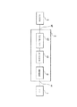
装置10は、この場合、以下のものが接続された通信バス101を有するマイクロコンピュータである。即ち、
中央ユニット100
リードオンリメモリ102
ランダムアクセスメモリ103(バッファメモリ103とも称する)
画面104
キーボード114
ハードディスク108
ディスク110を受け入れるよう適合されたディスクドライブ109
通信ネットワーク113と通信するためのインタフェース112
マイクロホン111に接続された入出力カード106
である。
【0067】
ハードディスク108は、以下に説明する本発明を実現するプログラムならびに本発明に従って符号化対象のデータと符号化されたデータとを記憶する。これらのプログラムは、ディスク110上で読み取るか、通信ネットワーク113を介して受信するか、またはリードオンリメモリ102に記憶することができる。
【0068】
より一般的に言えば、本発明に従うプログラムは記憶手段に記憶される。この記憶手段は、コンピュータまたはマイクロプロセッサによって読み取ることができる。この記憶手段は、装置内に統合されるかまたは統合されず、取外し可能なものにすることができる。例えば、これは、磁気テープ、ディスク、またはCD−ROM(固定メモリコンパクトディスク)を備えることができる。
【0069】
装置に電源を投入すると、本発明に従うプログラムがランダムアクセスメモリ103内に転送され、次に、そのメモリは本発明の実行可能コードと本発明を実現するために必要な変数を含むレジスタを含んでいる。このランダムアクセスメモリはバッファメモリ103を含んでいる。
【0070】
装置10は、デジタル写真装置、スキャナ、データを取得するかまたは記憶する他の手段などの周辺装置107から符号化対象のデータを受信することができる。
【0071】
また、装置10は、通信ネットワーク113を介して遠隔装置から符号化対象のデータを受信し、やはり通信ネットワーク113を介して符号化データを遠隔装置に伝送することもできる。
【0072】
また、装置10は、マイクロホン111から符号化対象のデータを受信することができる。その場合、このようなデータは音響信号である。
【0073】
画面104は、特に、ユーザに対し、符号化対象のデータを表示し、キーボード114とともにユーザインタフェースとして機能する。
【0074】
図4に関連して、変換回路21または解析回路は2つのレベルを有するダイアジック分解回路である。変換回路21は、本実施形態では、2のデシメータにそれぞれ関連付けられた従来の1組のフィルタであり、画像信号を2つの方向にフィルタリングして高空間周波数及び低空間周波数を有するサブバンド信号にするものである。ハイパスフィルタとローパスフィルタとの関係は、その信号の完全な再構成のための諸条件によって決定される。フィルタの様々な例については、以下に考慮する。但し、実際には一般にそのようになっているが、垂直分解フィルタと水平分解フィルタは同じである必要がないことに留意されたい。この場合、変換回路21は、2つの解像度レベルに応じて画像IMをサブバンド信号に分解するための2つの連続解析ユニットを有する。
【0075】
一般的に言えば、ある信号の解像度は、この信号を表すために使用する単位長あたりのサンプル数である。画像信号の場合、サブバンド信号の解像度はこのサブバンド信号を水平及び垂直に表すために使用する単位長あたりのサンプル数に関連する。この解像度は、実施されるデシメーション(decimation)の回数、デシメーション係数、及び初期画像の解像度に依存する。
【0076】
第1解析ユニットは、デジタル画像信号SIを受信し、それぞれローパスフィルタ210及びハイパスフィルタ220の2つのデジタルフィルタにそれを印加し、そのフィルタは画像信号を第1方向、例えば、画像信号の場合は水平にフィルタリングする。2のデシメータ(decimators by 2:2画素につき1画素間引く)D210及びD220を通過した後、結果的にフィルタリングされた信号は2つのローパスフィルタ230及び250と、ハイパスフィルタ240及び260にそれぞれ印加され、そのフィルタは、次に、第2方向、例えば、画像信号の場合は垂直にフィルタリングする。結果的にフィルタリングされた各信号はそれぞれの2のデシメータD230、D240、D250、D260を通過する。第1ユニットは、分解の際の最高解像度RES1を有する4つのサブバンド信号LL1、LH1、HL1、HH1を出力として供給する。
【0077】
サブバンド信号LL1は、画像信号の第1方向と第2方向の両方向の低周波成分またはサンプルを含んでいる。サブバンド信号LH1は、画像信号の第1方向の低周波成分と第2方向の高周波成分とを含んでいる。サブバンド信号HL1は、第1方向の高周波成分と第2方向の低周波成分とを含んでいる。そして、サブバンド信号HH1は、両方向の高周波成分を含んでいる。
【0078】
各サブバンド信号はオリジナル画像から構築された1組の実サンプルであり、所与の周波数帯域内の画像輪郭の垂直方向、水平方向、斜め方向にそれぞれ対応する情報を含んでいる。各サブバンド信号は1つの画像に同化することができる。
【0079】
サブバンド信号LL1は、解像度レベルRES2の4つのサブバンド信号LL2、LH2、HL2、HH2を供給するために、前のものと同様の解析ユニットによって解析される。
【0080】
解像度RES2のサブバンド信号のそれぞれもその画像の1つの方向に対応する。
【0081】
画像ソース1の出力側のデジタル画像IMの概略を図5に示し、一方で、図6は変換回路21により2つの解像度レベルに応じて画像IMを7つのサブバンドに分解した結果の画像IMDを表している。画像IMDはオリジナル画像IMと同じ量の情報を含むが、その情報は2つの解像度レベルに応じて頻繁に分解される。
【0082】
当然、解像度レベルの数と、その結果となるサブバンドの数は、異なるように選択することができ、例えば、画像などの2次元信号の場合、3つの解像度レベルで10のサブバンド、または4つの解像度レベルで13のサブバンドにすることができる。また、解像度レベルあたりのサブバンドの数も異なるものにすることができる。さらに、分解は非ダイアジック(dyadic)にすることができる。解析回路及び合成回路は処理された信号の次元に適合している。
【0083】
図6では、変換から発生するサンプルがサブバンドごとに配置されている。しかしながら、画像IMDは、いわゆるインタレースモードに従って同等に表すことができ、そのモードでは、様々なサブバンド信号のサンプルがその画像内のそれぞれの空間原点に応じてまとめてグループ化される。この表現は、変換された画像のサンプルを適切に計算することができ、即ち、それを計算するために使用したサンプルの代わりに計算されたサンプルがメモリ内に記憶されるという利点を有する。但し、適切な計算は本発明にとって不可欠なものではないことに留意されたい。
【0084】
以下、インタレース表現について論じる。インタレース表現を得ることを可能にする変換回路をトレリスの形で示す。
【0085】
図7は、1次元で1つの解像度レベルに応じてデジタル信号解析を実行する変換回路の機能を表すトレリスである。
【0086】
変換対象の信号の一部分、この場合は、11個のサンプルが示されている。但し、変換対象の各信号サンプルは1つのサンプルにするかまたは1つのシリーズのサンプルにすることができることに留意されたい。一例によれば、各サンプルは、1つのデジタル画像のうちの1つの行である。その場合、トレリスによって実施されるフィルタリングは、その画像の垂直フィルタリングである。同等の変形例としては、サンプルはその画像の列であり、フィルタリングはその画像の水平フィルタリングである。
【0087】
変換回路は、それぞれローパス及びハイパスである2つの関連フィルタH0及びH1を含んでいる。選択されたフィルタは5/3フィルタであり、以下のようにそれぞれのサンプルによって表すことができる。
【0088】
H0=[−1 2 6 2 −1]/8
H1=[−1 2 −1]/2
いわゆる、Sweldensの「リフティング」方法によれば、低周波フィルタH0は、以下のタイプの式により高周波フィルタH1の関数として表すことができる。
【0089】
H0=[0 0 1 0 0]+α.[1 0 1]*H1
式中、αは乗算計数であって、5/3フィルタの場合は0.25に等しく、「*」は畳込み演算を表す。このタイプの分解は、可逆性であると言われる。
【0090】
従って、低周波サンプルは高周波サンプル及びオリジナル信号のサンプルから計算される。
【0091】
以下、次のように示す。
【0092】
x2i-1、x2i、x2i+1、...は変換対象の信号のサンプルを示し、iは整数である。
【0093】
y2i-1、y2i、y2i+1、...は変換によって得られたサンプルを示す。この場合、偶数の指数を有するサンプルは低周波サンプルであり、奇数の指数を有するサンプルは高周波サンプルである。
【0094】
あるサンプルの指数は、その信号を形成する順序付けられたシリーズにおけるそのランクを表す。
【0095】
変換回路内で実行される計算は適切な計算であり、即ち、それを計算するために使用した同じランクの他のサンプルの代わりに所与のランクの計算されたサンプルが記憶される。
【0096】
さらに、変換対象の信号のサンプルは、ランクの昇順で順序付けられて処理される。
【0097】
このトレリスの第1行L1は、オリジナル信号のうち、フィルタリング対象のサンプル{...,x2i,x2i+1,...}を含み、このサンプルのランクは1ずつ変化する。これらのサンプルはフィルタリングに有用なので、バッファメモリ103に記憶される。
【0098】
このトレリスの第2行L2は、第1解像度レベルを有する高周波サンプル{...,y2i-1,y2i+1,...}を含み、このサンプルのランクは2ずつ変化する。この高周波サンプルは以下の公式によって得られる。
【0099】
y2i+1=x2i+1−0,5.(x2i+x2i+2)
それが計算された後、このサンプルは、オリジナル信号x2i+1内の同じランクのサンプルの代わりにバッファメモリ103に記憶される。
【0100】
このトレリスの第3行L3は、低周波サンプル{...,y2i,y2i+2,...}を含み、このサンプルのランクは2ずつ変化する。この低周波サンプルy2iは以下の公式によって得られる。
【0101】
y2i=x2i+0,25.(y2i-1+y2i+1)
それが計算された後、このサンプルは、オリジナル信号内の同じランクのサンプルx2iの代わりにバッファメモリ103に記憶される。
【0102】
5/3フィルタによるオリジナル信号{...,x2i,x2i+1,...}の変換の結果は、{...,y2i,y2i+1,...}という形式のインタレース信号になり、即ち、高周波サンプルと低周波サンプルの連続を有するものになる。
【0103】
当然、異なる数のサンプルまたは異なる数の解像度レベルについて同様の演算を実行するか、あるいは1つ以上の解像度レベルで他のフィルタを使用することは可能である。
【0104】
実際には、所定最大数のサンプルのみバッファメモリ103に記憶することができる。従って、バッファメモリ103に記憶されたサンプルを処理し、次に、後続シリーズのサンプルから再開するためには、この数に達したときに信号を切り出すことが必要である。前に提示した計算は、それに応じて適合させなければならない。
【0105】
発明者らは、2つの連続シリーズのサンプル間の境界の位置がその信号の再構成の品質に影響を及ぼすことを発見した。より詳細には、低周波サンプルの直後に置かれた境界は、その信号を再構成したときに現れる可能性のある不連続を制限する。
【0106】
事実、入力信号はサンプルx2iの後、即ち、低周波サンプルy2iの後に置かれた境界F1によって切り出される。前に提示した計算は、サンプルy2i+1までは影響を受けることはない。
【0107】
サンプルy2iを決定するためには、指数2iまでのサンプルのみが使用可能であり、後続サンプルは「未知」のものになる。サンプルy2iの計算は、サンプルy2i+1から発生する分岐を除去するように適合される。従って、サンプルy2iはサンプルy2i-1及びx2iの関数として決定される。サンプルy2iを決定するためには、例えば、対称反射原理、即ち、
y2i=x2i+0,25.(2×y2i-1)
を適用することが可能である。
【0108】
後続シリーズのサンプルを処理する場合、サンプルy2i+1からのように、境界F1がいかなる影響も及ぼさずにサンプルが決定され、即ち、境界F1の存在のためにいかなる分岐も除去されない。
【0109】
図8は、図7のトレリスに対応する逆変換回路または合成回路の機能を表すトレリスである。この場合、フィルタリング対象のサンプルは、あるデジタル画像の解析フィルタリング後に得られるインタレース高周波及び低周波サンプルである。これらのサンプルは、おそらく、解析と合成との間の他の処理によって変更されている。
【0110】
第1行L10は、サンプルのランクが2ずつ変化する低周波サンプル{...,y2i,y2i+2,...}とともにインタレースされた高周波サンプル{...,y2i-1,y2i+1,...}を含み、このサンプルのランクは2ずつ変化する。
【0111】
第2行L11は、再構成信号のうち、偶数ランクのサンプル{...,x2i,x2i+2,...}を含み、このサンプルのランクは2ずつ変化する。偶数ランクのサンプルx2iは以下の公式によって得られる。
【0112】
x2i=y2i−0,25.(y2i-1+y2i+1)
それが計算された後、このサンプルx2iは、サンプルy2iの代わりにバッファメモリ103に記憶される。
【0113】
第3行L12は、再構成信号のうち、奇数ランクのサンプル{...,x2i-1,x2i+1,...}を含み、このサンプルのランクは2ずつ変化する。奇数ランクのサンプルx2i+1は以下の公式によって得られる。
【0114】
x2i+1=y2i+1+0,5.(x2i+2+x2i)
それが計算された後、このサンプルx2i+1は、サンプルy2i+1の代わりにバッファメモリ103に記憶される。
【0115】
前述のように、サンプルのシリーズごとに信号を処理するためには、境界F2を置くことが必要である。境界F2は低周波サンプルy2iの後に置かれる。さらに、境界F2の位置は、解析に対応するように計算を適合させるために、境界F1の位置に依存する。言い換えれば、この場合、境界F2は、前の図で除去された分岐に対応する分岐を除去するように置かれ、解析と合成との間にいかなる処理も行われないときに信号の完全な再構成を保証する。
【0116】
従って、x2iの計算は境界F2に適合し、サンプルx2iはサンプルy2i-1及びy2iのみに依存する。他のサンプルは影響を受けない。後続の再構成されたサンプルx2i+1はサンプルx2iに特に依存し、これは再構成信号内の境界における不連続を制限する。
【0117】
図9は、1次元で1つの解像度レベルに応じてデジタル信号の解析を実行する他の変換回路の機能を表すトレリスである。この変換回路は、それぞれローパス及びハイパスである2つの関連フィルタH0及びH1を含んでいる。
【0118】
入力サンプルは、ランクの昇順で順序付けられて処理される。
【0119】
選択されたフィルタは13/7フィルタであり、例えば、ローパスフィルタH0及びハイパスフィルタH1として以下のフィルタを有する。
【0120】
H0=[−1 0 18 −16 −63 144 348 144 −63−16 18 0 −1]/512
H1=[1 0 −9 16 −9 0 1]/16
前に提示したものと同様の計算を実行することにより、トレリスのサンプル間で以下の関係が得られる。
【0121】
このトレリスの第1行L20は、フィルタリング対象のサンプル{...,x2i,x2i+1,...}を含み、このサンプルのランクは1ずつ変化する。これらのサンプルはフィルタリングに有用なので、バッファメモリ103に記憶される。
【0122】
このトレリスの第2行L21は、公式y2i+1=x2i+1−(−x2i-2+9.x2i+9.x2i+2−x2i+4)/16によって得られる高周波サンプル{...,y2i-1,y2i+1,...}を含み、このサンプルのランクは2ずつ変化する。
【0123】
それが計算された後、このサンプルy2i+1は、同じランクのオリジナル信号のサンプルの代わりにバッファメモリ103に記憶される。
【0124】
第3行L22は、公式y2i=x2i+(−y2i-3+9.y2i-1+9.y2i+1−y2i+3)/32によって得られる低周波サンプル{...,y2i,y2i+2,...}を含み、このサンプルのランクは2ずつ変化する。
【0125】
それが計算された後、このサンプルy2iは、同じランクのオリジナル信号のサンプルの代わりにバッファメモリ103に記憶される。
【0126】
境界F3は低周波サンプルy2iの後に置かれる。境界F3は低周波サンプルy2i-2、y2i-1、y2iの計算の変化を引き起こし、これは境界F3によって切り出された分岐を除去することからなる。というのは、境界の前に置かれたサンプルが計算されるときに、境界の後に置かれたサンプルは未知のものであるからである。従って、サンプルy2i-1はもはやサンプルx2i+2に依存せず、サンプルy2i-2及びy2iはもはやサンプルy2i+1に依存せず、サンプルy2iはもはやサンプルy2i+3に依存しない。
【0127】
境界F3の右側では、境界の存在によって計算が変更されることはない。
【0128】
図10は、図9のトレリスに対応する逆変換回路または合成回路の機能を表すトレリスである。
【0129】
このトレリスの第1行L30は、解析フィルタリングによって得られ、サンプルのランクが2ずつ変化する高周波サンプル{...,y2i-1,y2i+1,...}とともにインタレースされた低周波サンプル{...,y2i,y2i+2,...}を含み、このサンプルのランクは2ずつ変化する。
【0130】
このトレリスの第2行L31は、以下の公式によって得られ、再構成信号のうちの偶数ランクのサンプル{...,x2i,x2i+2,...}を含んでいる。
【0131】
x2i=y2i−(−y2i-3+9.y2i-1+9.y2i+1−y2i-3)/32
それが計算された後、このサンプルx2iは、同じランクの中間サンプルの代わりにバッファメモリ103に記憶される。
【0132】
このトレリスの第3行L32は、以下の公式によって得られ、再構成信号のうちの偶数ランクのサンプル{...,x2i-1,x2i+1,...}を含んでいる。
【0133】
x2i+1=y2i+1+(−x2i-2+9.x2i+9.x2i+2−x2i+4)/16
それが計算された後、このサンプルx2i+1は、同じランクの中間サンプルの代わりにバッファメモリ103に記憶される。
【0134】
前述のように、境界F4は低周波サンプルy2iの後に置かれる。これはサンプルx2i-2、x2i-1、x2iの計算の変化を引き起こし、これは境界F4によって切り出された分岐を除去することからなる。従って、サンプルx2i-2はもはやサンプルy2i+1に依存せず、サンプルx2i-1はもはやサンプルx2i+2に依存せず、サンプルx2iはもはやサンプルy2i+1及びy2i+3に依存しない。
【0135】
境界F4の右側では、境界の存在によって計算が変更されることはない。
【0136】
再構成信号のサンプルは、いずれもそれぞれの隣接サンプルに接続されるので、再構成信号には不連続がまったくない。
【0137】
図11は、1次元で3つの解像度レベルに応じてデジタル信号の解析(ダイアジック分解)を実行する他の変換回路の機能を表すトレリスである。この変換回路は、それぞれローパス及びハイパスである2つの関連フィルタH0及びH1を含んでいる。
【0138】
入力サンプルは、ランクの昇順で順序付けられて処理される。
【0139】
図7に示すように、選択されたフィルタは5/3フィルタである。前に提示したものと同様の計算を実行することにより、トレリスのサンプル間で以下の関係が得られる。
【0140】
このトレリスの第1行L40は、フィルタリング対象のサンプル{...,x2i,x2i+1,...}を含み、このサンプルのランクは1ずつ変化する。これらのサンプルはフィルタリングに有用なので、バッファメモリ103に記憶される。
【0141】
このトレリスの第2行L41は、公式t2i+1=x2i+1−0,5.(x2i+x2i+2)によって得られる、第1解像度レベルの高周波サンプル{...,t2i-1,t2i+1,...}を含み、このサンプルのランクは2ずつ変化する。
【0142】
それが計算された後、このサンプルt2i+1は、オリジナル信号内の同じランクのサンプルの代わりにバッファメモリ103に記憶される。
【0143】
このトレリスの第3行L42は、公式t2i=x2i+0,25.(t2i-1+t2i+1)によって得られる、第1解像度レベルの低周波サンプル{...,t2i-2,t2i,...}を含み、このサンプルのランクは2ずつ変化する。
【0144】
それが計算された後、このサンプルt2iは、オリジナル信号内の同じランクのサンプルの代わりにバッファメモリ103に記憶される。
【0145】
このトレリスの第4行L43は、公式v2i-2=t2i-2−0,5.(t2i+t2i-4)によって得られる、第2解像度レベルの高周波サンプル{...,v2i-2,v2i+2,...}を含み、このサンプルのランクは4ずつ変化する。
【0146】
それが計算された後、このサンプルv2i-2は、同じランクの第1レベルの低周波サンプルの代わりにバッファメモリ103に記憶される。
【0147】
このトレリスの第5の行L44は、公式v2i=t2i+0,25.(v2i-2+v2i+2)によって得られる、第2解像度レベルの低周波サンプル{...,v2i-4,v2i,...}を含み、このサンプルのランクは4ずつ変化する。
【0148】
それが計算された後、このサンプルv2iは、同じランクの第1レベルの低周波サンプルの代わりにバッファメモリ103に記憶される。
【0149】
このトレリスの第6の行L45は、公式y2i-4=v2i-4−0,5.(v2i+v2i-8)によって得られる、第3解像度レベルの高周波サンプル{...,y2i-4,y2i+4,...}を含み、このサンプルのランクは8ずつ変化する。
【0150】
それが計算された後、このサンプルy2i-4は、同じランクの第2レベルの低周波サンプルの代わりにバッファメモリ103に記憶される。
【0151】
このトレリスの第7の行L46は、公式y2i=v2i+0,25.(y2i-4+y2i+4)によって得られる、第3解像度レベルの低周波サンプル{...,y2i,y2i+8,...}を含み、このサンプルのランクは8ずつ変化する。
【0152】
それが計算された後、このサンプルy2iは、同じランクの第2レベルの低周波サンプルの代わりにバッファメモリ103に記憶される。
【0153】
前述のように、所定最大数のサンプルのみメモリ103に記憶することができる。従って、メモリ103に記憶されたサンプルを処理し、次に、後続シリーズのサンプルから再開するためには、この数に達したときに信号を切り出すことが必要である。
【0154】
発明者らは、2つの連続シリーズのサンプル間の境界の位置がその信号の再構成の品質に影響を及ぼすことも発見した。より詳細には、分解時に最低の解像度レベルを有する低周波サンプルの直後に置かれた境界は、その信号を再構成したときに現れる可能性のある不連続を制限する。
【0155】
事実、入力信号はサンプルx2iの後、即ち、最低レベルの低周波サンプルy2iの後に置かれた境界F5によって切り出される。前に提示した計算は指数2i−1を有するサンプルまでは影響を受けることはない。
【0156】
サンプルt2i、v2i、y2iを決定するためには、指数2iまでのサンプルのみが使用可能である。サンプルt2i、v2i、y2iの計算は、境界F5を切り出す分岐を除去するように適合される。従って、例えば、サンプルy2iはサンプルy2i-4及びv2iの関数としてのみ決定される。
【0157】
後続シリーズのサンプルを処理する場合、指数2i+1を有するサンプルからのように、境界F5がいかなる影響も及ぼさずにサンプルが決定され、即ち、境界F5の存在のためにいかなる分岐も除去されない。
【0158】
図12は、図11のトレリスに対応する逆変換回路または合成回路の機能を表すトレリスである。
【0159】
このトレリスの第1行L50は、サンプルのランクが8ずつ変化する第3解像度レベルの低周波サンプル{...,y2i,y2i+8,...}と、サンプルのランクが8ずつ変化する第3解像度レベルの高周波サンプル{...,y2i-4,y2i+4,...}を含んでいる。
【0160】
このトレリスの第2行L51は、公式v2i=y2i−0,25.(y2i-4+y2i+4)によって得られる、第2解像度レベルの再構成低周波信号のうち、偶数ランクのサンプル{...,v2i-8,v2i,...}を含み、このサンプルのランクは8ずつ変化する。
【0161】
それが計算された後、このサンプルv2iは、同じランクのサンプルy2iの代わりにバッファメモリ103に記憶される。
【0162】
このトレリスの第3行L52は、サンプルのランクが4ずつ変化する第2解像度レベルの高周波サンプル{...,v2i-2,v2i+2,...}と、公式v2i-4=y2i-4+0,5.(v2i-8+v2i)によって得られる、第2解像度レベルの再構成低周波信号のうち、サンプルのランクが8ずつ変化する奇数ランクのサンプル{...,v2i-4,v2i+4,...}を含んでいる。
【0163】
それが計算された後、このサンプルv2i-4は、同じランクのサンプルy2i-4の代わりにバッファメモリ103に記憶される。
【0164】
このトレリスの第4行L53は、公式t2i=v2i−0,25.(v2i-2+v2i+2)によって得られる、第1解像度レベルの再構成低周波信号のうち、奇数ランクのサンプル{...,t2i-4,t2i,...}を含み、このサンプルのランクは4ずつ変化する。
【0165】
それが計算された後、このサンプルt2iは、同じランクのサンプルv2iの代わりにバッファメモリ103に記憶される。
【0166】
このトレリスの第5の行L54は、サンプルのランクが2ずつ変化する第1レベルの高周波サンプル{...,t2i-1,t2i+1,...}と、公式t2i-2=v2i-2+0,5.(t2i-4+t2i)によって得られる、第1解像度レベルの再構成低周波信号のうち、サンプルのランクが4ずつ変化する奇数ランクのサンプル{...,t2i-2,t2i+2,...}を含んでいる。
【0167】
それが計算された後、このサンプルt2i-2は、同じランクのサンプルv2i-2の代わりにバッファメモリ103に記憶される。
【0168】
このトレリスの第6の行L55は、公式x2i=t2i−0,25.(t2i-1+t2i+1)によって得られる、再構成信号のうち、偶数ランクのサンプル{...,x2i,x2i+2,...}を含んでいる。
【0169】
それが計算された後、このサンプルx2iは、同じランクのサンプルt2iの代わりにバッファメモリ103に記憶される。
【0170】
このトレリスの第7の行L56は、公式x2i+1=t2i+1+0,5.(x2i+x2i+2)によって得られる、再構成信号のうち、奇数ランクのサンプル{...,x2i-1,x2i+1,...}を含んでいる。
【0171】
それが計算された後、このサンプルx2i+1は、同じランクのサンプルt2i+1の代わりにバッファメモリ103に記憶される。
【0172】
前述のように、境界F6は最低レベルの低周波サンプルy2iの後に置かれる。サンプルv2i、t2i、x2iの計算は、それぞれについて境界F6によって切り出される分岐を除去するように適合される。
【0173】
指数2i−1までのサンプルの計算は、指数2i+1からのように、境界F6による影響を受けることはない。
【0174】
各解像度レベルの第2ステップで計算される係数、即ち、この場合は行L52、L54、L56で計算され、そこに示される係数は、それぞれの隣接物への分岐によって接続されるが、その分岐はいずれも境界F6の存在のために除去される。従って、境界F6が存在するので、再構成信号には不連続がまったくない。
【0175】
図13及び図14はそれぞれ図11及び図12のものと同一のトレリスであるが、境界F7及びF8は、最低解像度レベルではなくすぐ上のレベルに属する低周波サンプルv2i-4の後に置かれる。
【0176】
図13の行L40〜L46は図11のものと同一である。サンプルt2i-4、v2i-4、y2i-4の計算は、境界F7の後に置かれるサンプル、即ち、この場合は2i−3より大きいかまたはそれと等しい指数を有するサンプルを考慮に入れないように、境界F7の存在に適合している。
【0177】
同様に、図14の行L50〜L56は図12のものと同一である。境界F8は、境界F7のものに対応する変化を引き起こすように置かれている。サンプルv2i-4、t2i-4、x2i-4の計算は、境界F8の後に置かれるサンプル、即ち、この場合は2i−3より大きいかまたはそれと等しい指数を有するサンプルを考慮に入れないように、境界F8の存在に適合している。
【0178】
発明者らは、図13及び図14のフィルタに従う解析及び合成の後の再構成信号が、図11及び図12のフィルタに従う解析及び合成の後の再構成信号よりわずかに多いひずみを有することを発見した。
【0179】
これは、図12の場合とは異なり、行L52で計算され、そこに示されるサンプルが除去された分岐を有し、それが再構成信号においてひずみを発生することによるものである。
【0180】
図15は、1次元で3つの解像度レベルに応じてデジタル信号の解析(ダイアジック分解)を実行する変換回路の機能を表すトレリスである。この変換回路は、それぞれローパス及びハイパスである2つの関連フィルタH0及びH1を含んでいる。
【0181】
変換対象の信号の一部分、この場合は17個のサンプルが示されている。但し、変換対象の各信号サンプルは1つのサンプルにするかまたは1つのシリーズのサンプルにすることができることに留意されたい。一例によれば、各サンプルは1つのデジタル画像のうちの1つの行である。その場合、トレリスによって実施されるフィルタリングはその画像の垂直フィルタリングである。同等の変形例としては、サンプルはその画像の列であり、フィルタリングはその画像の水平フィルタリングである。
【0182】
変換回路は、それぞれローパス及びハイパスである2つの関連フィルタH0及びH1を含んでいる。選択されたフィルタは5/3フィルタであり、以下のようにそれぞれのサンプルによって表すことができる。
【0183】
H0=[−1 2 6 2 −1]/8
H1=[−1 2 −1]/2
いわゆるSweldensの「リフティング」方法によれば、低周波フィルタH0は、以下のタイプの式により高周波フィルタH1の関数により表すことができる。
【0184】
H0=[0 0 1 0 0]+α.[1 0 1]*H1
式中、αは乗算計数であって、5/3フィルタの場合は0.25に等しく、「*」は畳込み演算を表す。このタイプの分解は可逆性であると言われる。
【0185】
従って、低周波サンプルは高周波サンプル及びオリジナル信号のサンプルから計算される。
【0186】
以下、次のように示す。
【0187】
x2i-1、x2i、x2i+1、...は変換対象の信号のサンプルを示し、iは整数である。
【0188】
y2i-1、y2i、y2i+1、...は変換によって得られたサンプルを示す。この場合、偶数の指数を有するサンプルは低周波サンプルであり、奇数の指数を有するサンプルは高周波サンプルである。
【0189】
あるサンプルの指数は、その信号を形成する順序付けられたシリーズにおけるそのランクを表す。
【0190】
変換回路内で実行される計算は適切な計算であり、即ち、それを計算するために使用した同じランクの他のサンプルの代わりに所与のランクの計算されたサンプルが記憶される。
【0191】
さらに、変換対象の信号のサンプルは、ランクの昇順で順序付けられて処理される。
【0192】
このトレリスの第1行L10は、フィルタリング対象のサンプル{...,x2i,x2i+1,...}を含み、このサンプルのランクは1ずつ変化する。これらのサンプルはフィルタリングに有用なので、バッファメモリ103に記憶される。
【0193】
このトレリスの第2行L11は、公式t2i+1=x2i+1−0,5.(x2i+x2i+2)によって得られる、第1解像度レベルの高周波サンプル{...,t2i-1,t2i+1,...}を含み、このサンプルのランクは2ずつ変化する。
【0194】
それが計算された後、このサンプルt2i+1は、オリジナル信号内の同じランクのサンプルの代わりにバッファメモリ103に記憶される。
【0195】
このトレリスの第3行L12は、公式t2i=x2i+0,25.(t2i+1+t2i-1)によって得られる、第1解像度レベルの低周波サンプル{...,t2i-2,t2i,...}を含み、このサンプルのランクは2ずつ変化する。
【0196】
それが計算された後、このサンプルt2iは、オリジナル信号内の同じランクのサンプルの代わりにバッファメモリ103に記憶される。
【0197】
このトレリスの第4行L13は、公式v2i-2=t2i-2−0,5.(t2i+t2i-4)によって得られる、第2解像度レベルの高周波サンプル{...,v2i-2,v2i+2,...}を含み、このサンプルのランクは4ずつ変化する。
【0198】
それが計算された後、このサンプルv2i-2は、同じランクの第1レベルの低周波サンプルの代わりにバッファメモリ103に記憶される。
【0199】
このトレリスの第5の行L14は、公式v2i=t2i+0,25.(v2i-2+v2i+2)によって得られる、第2解像度レベルの低周波サンプル{...,v2i-4,v2i,...}を含み、このサンプルのランクは4ずつ変化する。
【0200】
それが計算された後、このサンプルv2iは、同じランクの第1レベルの低周波サンプルの代わりにバッファメモリ103に記憶される。
【0201】
このトレリスの第6の行L15は、公式y2i-4=v2i-4−0,5.(v2i+v2i-8)によって得られる、第3解像度レベルの高周波サンプル{...,y2i-4,y2i+4,...}を含み、このサンプルのランクは8ずつ変化する。
【0202】
それが計算された後、このサンプルy2i-4は、同じランクの第2レベルの低周波サンプルの代わりにバッファメモリ103に記憶される。
【0203】
このトレリスの第7の行L16は、公式y2i=v2i+0,25.(y2i-4+y2i+4)によって得られる、第3解像度レベルの低周波サンプル{...,y2i-8,y2i,...}を含み、このサンプルのランクは8ずつ変化する。
【0204】
それが計算された後、このサンプルy2iは、同じランクの第2レベルの低周波サンプルの代わりにバッファメモリ103に記憶される。
【0205】
5/3フィルタによるオリジナル信号{...,x2i,x2i+1,...}の変換の結果は、インタレース信号になる。当然、異なる数のサンプルまたは異なる数の解像度レベルについて同様の演算を実行するか、あるいは1つ以上の解像度レベルで他のフィルタを使用することは可能である。
【0206】
実際には、所定最大数のサンプルのみバッファメモリ103に記憶することができる。従って、連続ブロックのサンプルにより信号を処理することが必要である。
【0207】
しかしながら、その解析とその合成との間にその信号について実行される量子化またはエントロピ符号化などの処理は、ブロックごとに処理するために合成中に不連続を引き起こす可能性がある。
【0208】
信号の再構成時のこのような不連続を回避するために、2つの隣接ブロック間にオーバラップが必要である。2つの隣接ブロックは所定数のサンプルにオーバラップする。
【0209】
本発明は、隣接ブロック間のオーバラップを保証するために、ブロックの形成とブロックの極限を位置決めする方法に特に関係する。
【0210】
このため、左極限と呼ばれる第1極限がまず第一に定義される。xgと示されるサンプルが第1行L10で選択される。このサンプルxgから、サンプルxgのランクに等しいかまたはそれより高いランクのサンプルへの分岐をたどって後続行L11に移行することにより、左極限が形成される。図15に示す例では、サンプルxgから、左極限は、分岐に続く後続行L11からサンプルxgに等しいかあるいは大きいランクのサンプルへ通過することによって形成され、この場合、ランクは等しい。
【0211】
次に、トレリスの最後の行L16内のサンプルygまで、ある行から後続行に移行するために同じ規則が適用される。従って、所与の行内のあるサンプルから後続行内の等しいかまたはより高いランクのサンプルに移行すると、左極限が形成される。この左極限は、前のサンプルから前のサンプルに応じて計算された次のサンプルに連続的に移行することによって形成される。但し、サンプルxgを使用する極限は固有のものではないことに留意されたい。
【0212】
同等に、右極限と呼ばれる第2極限が定義される。xdと示されるサンプルが第1行L10で選択される。このサンプルxdから、サンプルxdのランクより低いかまたはそれに等しいランクのサンプルへの分岐をたどって後続行L11に移行することにより、右極限が形成される。
【0213】
次に、トレリスの最後の行L16内のサンプルydまで、ある行から後続行に移行するために同じ規則が適用される。従って、所与の行内のあるサンプルから後続行内のより低いかまたは等しいランクのサンプルに移行すると、右極限が形成される。この右極限は、前のサンプルから前のサンプルに応じて計算された次のサンプルに連続的に移行することによって形成される。
【0214】
検討したサンプルは、トレリス内のいずれか1つであり、そのランクがその極限及び検討中のサンプルと同じ行に属するサンプルのランクより低いかまたはそれより高い場合、それが右極限であろうと左極限であろうと、極限の左側または右側にそれぞれ位置することができる。
【0215】
さらに、そのランクがその極限及び検討中のサンプルと同じ行に属するサンプルのランクより厳密に低いかまたは厳密にそれより高い場合、どのサンプルも厳密に極限の左側または厳密に極限の右側にあると言われることになる。
【0216】
前記サンプルは、そのランクがその極限及び検討中のサンプルと同じ行に属するサンプルのランクより低いかまたはそれに等しいか、あるいは厳密に高いかまたはそれに等しい場合、極限の広い意味で左側またはの右側にあると言われることになる。
【0217】
さらに、厳密に左極限の左側と厳密に右極限の右側の両方にトレリス内のいかなるサンプルも位置していない場合、即ち、言い換えれば、第1後続入力ブロックの開始極限及び互換性サンプルと同じ行に属するサンプルのランクより厳密に低いランクを有し、同時に検討した第1後続入力ブロックの終了極限及び互換性サンプルと同じ行に属するサンプルのランクより厳密に高いランクを有する互換性サンプルがまったくない場合に、左極限と右極限は互換性があると言われる。
【0218】
右極限は第1入力ブロックBE1の終了を決定する。このブロックでは、右極限を含むそこまでのサンプルは計算を行うために使用され、後続サンプルは「未知」のものになる。ブロックBE1に属し、その結果として計算されるサンプルに未知のサンプルを接続する分岐は除去される。除去される分岐は、図示の例では3つあり、点線で示されている。
【0219】
同等に、左極限は第2入力ブロックBE2の開始を決定する。このブロックでは、左極限を含むそこまでのサンプルは計算を行うために使用され、前のサンプルは「未知」のものになる。ブロックBE2に属し、その結果として計算されるサンプルに未知のサンプルを接続する分岐は除去される。除去される分岐は、図示の例では3つあり、点線で示されている。
【0220】
上記で定義した意味の範囲内で、左極限と右極限は互換性がある。
【0221】
以下に開示するように、計算は、分岐の除去の結果として適合している。
【0222】
従って、入力ブロックBE1及びBE2はサンプルxgとxdとの間でオーバラップする。
【0223】
入力ブロックBE1及びBE2にそれぞれ対応する出力ブロックBS1及びBS2を決定するために、以下の特性に適合する2つのサンプルy1及びy2が選択される。
【0224】
サンプルy1及びy2は連続ランクのものである。
【0225】
サンプルy1は、サンプルy1のランクより低いかまたはそれに等しいランクを有するそのトレリスのすべてのサンプルがその用語の広い範囲内で右経路の左側になり、即ち、好ましくは、右極限上になるような位置を有する。
【0226】
サンプルy2は、サンプルy2のランクより高いかまたはそれに等しいランクを有するそのトレリスのすべてのサンプルがその用語の広い範囲内で左経路の右側になり、即ち、好ましくは、左極限上になるような位置を有する。
【0227】
出力ブロックBS1とBS2との間の境界FS1は、サンプルy1=t2i-5とy2=y2i-4との間におかれる。
【0228】
図16は、図15のトレリスに対応する逆変換回路または合成回路の機能を表すトレリスである。この場合、フィルタリング対象のサンプルは、あるデジタル画像の解析フィルタリング後に得られるインタレース高周波及び低周波サンプルである。これらのサンプルは、ことによると、解析と合成との間の他の処理によって変更されている。
【0229】
このトレリスの第1行L20は、サンプルのランクが8ずつ変化する第3解像度レベルの低周波サンプル{...,y2i-8,y2i,...}と、サンプルのランクが8ずつ変化する第3解像度レベルの高周波サンプル{...,y2i-4,y2i+4,...}を含んでいる。
【0230】
このトレリスの第2行L21は、公式v2i=y2i−0,25.(y2i-4+y2i+4)によって得られる、第2解像度レベルの再構成低周波信号のうちの偶数ランクのサンプル{...,v2i-8,v2i,...}を含み、このサンプルのランクは8ずつ変化する。
【0231】
それが計算された後、このサンプルv2iは、同じランクのサンプルy2iの代わりにバッファメモリ103に記憶される。
【0232】
このトレリスの第3行L22は、サンプルのランクが4ずつ変化する第2解像度レベルの高周波サンプル{...,v2i-2,v2i+2,...}と、公式v2i-4=y2i-4+0,5.(v2i-8+v2i)によって得られる、第2解像度レベルの再構成低周波信号のうちの奇数ランクのサンプル{...,v2i-4,v2i+4,...}を含み、このサンプルのランクは8ずつ変化する。
【0233】
それが計算された後、このサンプルv2i-4は、同じランクのサンプルy2i-4の代わりにバッファメモリ103に記憶される。
【0234】
このトレリスの第4行L23は、公式t2i=v2i−0,25.(v2i-2+v2i+2)によって得られる、第1解像度レベルの再構成低周波信号のうちの偶数ランクのサンプル{...,t2i-4,t2i,...}を含み、このサンプルのランクは4ずつ変化する。
【0235】
それが計算された後、このサンプルt2iは、同じランクのサンプルv2iの代わりにバッファメモリ103に記憶される。
【0236】
このトレリスの第5の行L24は、サンプルのランクが2ずつ変化する第1レベルの高周波サンプル{...,t2i-1,t2i+1,...}と、公式t2i-2=v2i-2+0,5.(t2i-4+t2i)によって得られる、第1解像度レベルの再構成低周波信号のうちの奇数ランクのサンプル{...,t2i-2,t2i+2,...}を含み、このサンプルのランクは4ずつ変化する。
【0237】
それが計算された後、このサンプルt2i-2は、同じランクのサンプルv2i-2の代わりにバッファメモリ103に記憶される。
【0238】
このトレリスの第6の行L25は、公式x2i=t2i−0,25.(t2i-1+t2i+1)によって得られる、再構成信号のうちの偶数ランクのサンプル{...,x2i,x2i+2,...}を含んでいる。
【0239】
それが計算された後、このサンプルx2iは、同じランクのサンプルt2iの代わりにバッファメモリ103に記憶される。
【0240】
このトレリスの第7の行L26は、公式x2i+1=t2i+1+0,5.(x2i+x2i+2)によって得られる、再構成信号のうちの奇数ランクのサンプル{...,x2i-1,x2i+1,...}を含んでいる。
【0241】
それが計算された後、このサンプルx2i+1は、同じランクのサンプルt2i+1の代わりにバッファメモリ103に記憶される。
【0242】
前述のように、信号はサンプルのブロックごとに処理される。ブロックの終了とブロックのオーバラップに関する同じ考慮事項が適用される。
【0243】
さらに、ブロックの開始及び終了における境界は、可逆分解の場合は解析と合成との間の処理がない時の信号の完全な再構成を保証するために、解析に対応するように置かれる。従って、除去される分岐は解析時に除去される分岐に対応し、言い換えれば、計算は解析に対応するように適合される。
【0244】
入力ブロックBE3はサンプルv2i+2の後で終了し、後続入力ブロックBE4はサンプルt2i-9から始まる。入力ブロックBE3及びBE4はランク2i−9及び2i+2のサンプル間でオーバラップする。
【0245】
同様に、隣接出力ブロックBS3及びBS4が形成される。出力ブロックBS3及びBS4は出力ブロックBS1及びBS2に対応する。出力ブロックBS3はランク2i−5の後で終了し、ブロックBS4はランク2i−4から始まる。
【0246】
分岐は除去され、その結果、所与のサンプルの計算は解析に対応するように変更される。
【0247】
図17及び図18はそれぞれ図15及び図16のトレリスと同一のトレリスであるが、そのブロックは1つのサンプルだけにオーバラップし、そのサンプルは最小オーバラップを構成し、その結果、メモリ占有を最小限にする。この事例は奇数フィルタに適用可能である。
【0248】
図17では、左経路と右経路が併合され、同じサンプルxg=xdから形成される。その結果、左経路と右経路は同じランクのサンプルのみを含んでいる。
【0249】
入力ブロックBE5及びBE6が形成され、入力サンプルxg=xdにオーバラップするだけである。
【0250】
入力サンプルxg=xdは、低周波サンプルである計算されたサンプルと同じランクを有する。さらに、この計算されたサンプルは、この場合、出力サンプルであり、即ち、最低解像度レベルの低周波サンプルである。
【0251】
入力ブロックBE5が処理されると、3つの分岐が除去され、計算はそれに応じて適合される。
【0252】
同様に、入力ブロックBE6が処理されると、3つの分岐が除去され、計算はそれに応じて適合される。
【0253】
また、隣接出力ブロックBS5及びBS6が形成される。出力ブロックBS5とBS6との間の境界FS5は、入力サンプルxg=xdと同じランクを有する出力サンプルの直前に位置する。同等に、その境界はこのサンプルの直後に置くこともできる。
【0254】
図18は、図17のトレリスに対応する逆変換回路または合成回路の機能を表すトレリスである。
【0255】
従って、2つの入力ブロックBE7及びBE8は1つの入力サンプルにオーバラップする。
【0256】
計算分岐は除去され、計算は解析に対応するように適合される。
【0257】
隣接出力ブロックBS7及びBS8が形成される。その境界は、オーバラップサンプルと同じランクの出力サンプルの直前に置かれる。
【0258】
次に、計算分岐が除去されるときに計算が適合される方法について詳細を示す。その結果、分岐に関連する重み係数に関心が向けられる。
【0259】
図19は、1次元で2通りのダイアジック分解レベルに応じてデジタル信号の解析を実行する他の変換回路の機能を表すトレリスである。この変換回路は、それぞれローパス及びハイパスである2つの関連フィルタH0及びH1を有する。
【0260】
入力サンプルは、ランクの昇順で順序付けられて処理される。
【0261】
選択された実施形態によれば、選択したフィルタは9/7フィルタであり、例えば、Ingrid DAUBECHIESによる「Ten lectureson wavelets」(CBMS−NSF Regional Conference Series in Applied MathematicsVol.61 SIAM,Journal of Mathematics Anal.Philadelphia PA 1992)という論文に開示されているものである。
【0262】
前に提示したものと同様の計算を実行することにより、トレリスのサンプル間で以下の関係が得られる。
【0263】
このトレリスの第1行L30は、フィルタリング対象のサンプル{...,x2i,x2i+1,...}を含み、このサンプルのランクは1ずつ変化する。これらのサンプルはフィルタリングに有用なので、バッファメモリ103に記憶される。
【0264】
以下、a1、b1、a2、b2、a3、b3、a4、b4は実係数であり、一例としてその値を示す。いずれの場合も、係数b1、b2、b3は非ゼロである。
【0265】
このトレリスの第2行L31は、第1分解レベル用の第1段階であり、公式t2i+1=b1.x2i+1+a1.(x2i+x2i+2)、即ち、特定の場合はt2i+1=x2i+1−1,586134.(x2i+x2i+2)によって得られる中間サンプル{...,t2i-1,t2i+1,...}を含み、このサンプルのランクは2ずつ変化する。
【0266】
それが計算された後、このサンプルt2i+1は、オリジナル信号内の同じランクのサンプルの代わりにバッファメモリ103に記憶される。
【0267】
このトレリスの第3行L32は、第1分解レベル用の第2段階であり、公式v2i=b2.x2i+a2.(t2i+1+t2i-1)、即ち、v2i=x2i−0,052980.(t2i+1+t2i-2)によって得られる中間サンプル{...,v2i,v2i+2,...}を含み、このサンプルのランクは2ずつ変化する。
【0268】
それが計算された後、このサンプルv2iは、オリジナル信号内の同じランクのサンプルの代わりにバッファメモリ103に記憶される。
【0269】
このトレリスの第4行L33は、第1分解レベル用の第3段階であり、公式y2i+1=b3.t2i+1+a3.(v2i+v2i+2)、即ち、y2i+1=t2i+1+0,882911.(v2i+v2i+2)によって得られる、第1レベルの高周波サンプル{...,y2i-1,y2i+1,...}を含み、このサンプルのランクは2ずつ変化する。
【0270】
それが計算された後、このサンプルy2i+1は、同じランクの中間サンプルの代わりにバッファメモリ103に記憶される。
【0271】
このトレリスの第5の行L34は、第1分解レベル用の第4段階であり、公式y2i=b4.v2i+a4.(y2i+1+y2i-1)、即ち、y2i=v2i+0,443507.(y2i+1+y2i-1)によって得られる、第1レベルの低周波サンプル{...,y2i,y2i+2,...}を含み、このサンプルのランクは2ずつ変化する。
【0272】
それが計算された後、このサンプルy2iは、同じランクの中間サンプルの代わりにバッファメモリ103に記憶される。
【0273】
次に、サンプルy2i及びy2i+1は正規化される。表記を簡略化するため、正規化されたサンプルはy2i及びy2i+1と呼ぶ。これらの正規化公式は以下の通りである。
【0274】
y2i=y2i/K0
y2i+1=y2i+1.K1
式中、K0及びK1は、9/7フィルタの場合に0.869865に等しい正規化係数である。
【0275】
それらが計算された後、このサンプルは、初期サンプルy2i及びy2i+1の代わりにバッファメモリ103に記憶される。
【0276】
第2分解レベルに使用するサンプルは正規化されたサンプルになる。
【0277】
このトレリスの第6の行L35は、第2分解レベル用の第1段階であり、公式t1 2i=b1.y2i+a1.(y2i-2+y2i+2)、即ち、t1 2i=y2i−1,586134.(y2i-2+y2i+2)によって得られる中間サンプル{...,t1 2i,t1 2i+4,...}を含み、このサンプルのステップは4ずつ変化する。
【0278】
それらが計算された後、このサンプルt1 2iは、同じランクのサンプルy2iの代わりにバッファメモリ103に記憶される。
【0279】
このトレリスの第7の行L36は、第2分解レベル用の第2段階であり、公式v1 2i+2=b2.y2i+2+a2.(t1 2i+t1 2i+4)、即ち、v1 2i+2=y2i+2−0,052980.(t1 2i+t1 2i+4)によって得られる中間サンプル{...,v1 2i-2,v1 2i+2,...}を含み、このサンプルのランクは4ずつ変化する。
【0280】
それが計算された後、このサンプルv1 2i+2は、同じランクのサンプルy2i+2の代わりにバッファメモリ103に記憶される。
【0281】
このトレリスの第8の行L37は、第2分解レベル用の第3段階であり、公式y1 2i=b3.t1 2i+a3.(v1 2i-2+v1 2i+2)、即ち、y1 2i=t1 2i+0,882911.(v1 2i-2+v1 2i+2)によって得られる、第2レベルの高周波サンプル{...,y1 2i,y1 2i+4,...}を含み、このサンプルのランクは4ずつ変化する。
【0282】
それが計算された後、このサンプルy1 2iは、同じランクの中間サンプルの代わりにバッファメモリ103に記憶される。
【0283】
このトレリスの第9の行L38は、第2分解レベル用の第4段階であり、公式y1 2i+2=b4.v1 2i+2+a4.(y1 2i+y1 2i+4)、即ち、y1 2i+2=v1 2i+2+0,443507.(y1 2i+y1 2i+4)によって得られる、第2レベルの低周波サンプル{...,y1 2i-2,y1 2i+2,...}を含み、このサンプルのランクは4ずつ変化する。
【0284】
それが計算された後、このサンプルy1 2i+2は、同じランクの中間サンプルの代わりにバッファメモリ103に記憶される。
【0285】
次に、サンプルy1 2i及びy1 2i+1は正規化される。表記を簡略化するため、正規化されたサンプルはy1 2i及びy1 2i+1と呼ぶ。これらの正規化公式は以下の通りである。
【0286】
y1 2i=y1 2i.K1
y1 2i+2=y1 2i+2/K0
式中、K0及びK1は、0.869865に等しい。
【0287】
それらが計算された後、このサンプルは、初期サンプルy1 2i及びy1 2i+2の代わりにバッファメモリ103に記憶される。
【0288】
9/7フィルタによるオリジナル信号{...,x2i,x2i+1,...}の変換、この場合は2通りのレベルのダイアジック分解の結果は、{...,y1 2i-2,y2i-1,y1 2i,y2i+1,y1 2i+2,...}という形式のインタレース信号、即ち、第2レベルの低周波サンプル、第1レベルの高周波サンプル、第2レベルの高周波サンプル、第1レベルの高周波サンプルなどのサンプルの連続を有するものである。
【0289】
前述のように、所与のサンプルの計算のために入力ブロック及び出力ブロックが形成され、分岐が除去される。
【0290】
この場合の中央分岐は、同じランクを備え、異なる2つの行に属する2つのサンプルを接続する分岐を意味し、非中央分岐は、異なるランクで異なる行に属する2つのサンプルを接続する分岐を意味する。
【0291】
但し、除去される分岐は中央分岐ではないことに留意されたい。
【0292】
可逆分解の正規化特性を保持するために、分岐の除去により少なくとも1つの他の分岐の係数が変更される。
【0293】
分岐の除去に関連する変更は中央分岐について実施され、その結果、除去される分岐と同じサンプルが得られる。
【0294】
例えば、図19では、サンプルz4=y1 2i+2の計算は、サンプルz1=y1 2i及びz3=y1 2i+4から得られる分岐の除去を考慮に入れるために変更される。
【0295】
前の低サブバンドのすべてのサンプルが1に等しい場合に、このサンプルが持つと思われる値として考慮されるサンプルについて全重みPが定義される。前の低サブバンドはオリジナル信号にすることができる。サンプルz1、z2=v1 2i+2、z3の場合、前の低サブバンドは行L34上になる。
【0296】
従って、例えば、以下のようになる。
【0297】
P(z1)=b3.(b1+2.a1)+2.a3.(b2+2.a2.(b1+2.a1))
P(z2)=b2+2.a2.(b1+2.a1)
P(z3)=b3.(b1+2.a1)+2.a3.(b2+2.a2.(b1+2.a1))
非中央分岐が除去されると、この除去される分岐の重み係数と除去される分岐の発生元であるサンプルの全重みとの積をそれに加えることにより、結果的に同じサンプルが得られる中央分岐の重み係数が変更され、この積については中央分岐の発生元であるサンプルの重みによる除算も行われる。
【0298】
従って、サンプルz1及びz3から得られる2つの分岐の除去を考慮に入れるために、サンプルy1 2i+2に至る分岐の変更された重み係数b’4は以下の式に等しくなる。
【0299】
b4+a4.P(z1)/P(z2)+a4.P(z3)/P(z2)
但し、除去された他の非中央分岐の場合、除去された各分岐の重み係数は同じサンプルに至る非中央分岐にそれぞれ追加されていることに留意されたい。従って、例えば、t2i-1=b1.x2i-1+2.a1.x2iになる。
【0300】
変形例として、除去される分岐の重みは、一部は中央分岐に、一部は非中央分岐に移転することができる。
【0301】
対応する合成フィルタの重み係数は同じように変更される。
【0302】
図20は、本発明に従うデジタル信号符号化アルゴリズムを示している。
【0303】
このアルゴリズムは、符号化装置で実現され、ステップE1〜E5を含んでいる。
【0304】
この符号化アルゴリズムは、マイクロプロセッサと協働可能な情報記憶手段に全部または一部を記憶することができる。この記憶手段は、コンピュータまたはマイクロプロセッサによって読み取ることができる。この記憶手段は、装置内に統合されるかまたは統合されず、取外し可能なものにすることができる。例えば、これは、磁気テープ、ディスク、またはCD−ROM(固定メモリコンパクトディスク)を含むことができる。
【0305】
ステップE1は、符号化対象の信号の1つのシリーズのサンプル、例えば、1つの入力ブロックの読取りである。
【0306】
次のステップE2は、読み取られたシリーズのサンプルの変換である。この変換は、例えば前述のような解析フィルタリングである。
【0307】
ステップE2に続いてステップE3が行われ、そこでそのシリーズのフィルタリング済みサンプルが量子化される。
【0308】
次のステップE4は、前に量子化したデータのエントロピ符号化である。
【0309】
符号化対象の信号のすべてのシリーズのサンプルについて、ステップE1〜E4を繰り返す。
【0310】
ステップE4に続いてステップE5が行われるが、それは符号化されたデータの使用、例えば、その伝送である。但し、符号化されたシリーズのサンプルは、それが形成されたときにまたはすべてのシリーズの信号が符号化されたときに伝送できることに留意されたい。
【0311】
図21は、本発明に従うデジタル信号復号化アルゴリズムを示している。
【0312】
このアルゴリズムは、復号化装置で実現され、ステップE10〜E14を含んでいる。
【0313】
この復号化アルゴリズムは、マイクロプロセッサと協働可能な情報記憶手段に全部または一部を記憶することができる。この記憶手段は、コンピュータまたはマイクロプロセッサによって読み取ることができる。この記憶手段は、装置内に統合されるかまたは統合されず、取外し可能なものにすることができる。例えば、これは、磁気テープ、ディスク、またはCD−ROM(固定メモリコンパクトディスク)を含むことができる。
【0314】
ステップE10は、復号化対象の1つのシリーズのサンプルの読取りである。
【0315】
次のステップE11は、前に読み取ったデータのエントロピ復号化である。
【0316】
次のステップE12は、前のステップで復号化したデータの逆量子化である。
【0317】
次に、逆量子化したデータに対してステップE13の逆変換、例えば、前述したように合成フィルタリングが行われる。
【0318】
復号化対象のすべてのシリーズのサンプルについて、ステップE10〜E13を繰り返す。
【0319】
ステップE13に続いて、復号化したデータの使用、例えば、画像信号の場合はそれらの表示であるステップE14が行われる。
【0320】
当然、本発明は、前述し図示した実施形態に制限されることはないが、正反対に当業者の能力の範囲内であればどのような変形例も包含する。
【0321】
特に、本発明は、デジタル信号符号化の分野に制限されず、変換され、次に、再構成される信号のひずみを最小限にしようとする場合の信号処理のすべての分野に適用される。
【0322】
尚、本発明は、複数の機器(例えばホストコンピュータ、インタフェース機器、リーダ、プリンタなど)から構成されるシステムに適用しても、一つの機器からなる装置(例えば、複写機、ファクシミリ装置など)に適用してもよい。
【0323】
また、本発明の目的は、前述した実施形態の機能を実現するソフトウェアのプログラムコードを記録した記憶媒体を、システムあるいは装置に供給し、そのシステムあるいは装置のコンピュータ(またはCPUやMPU)が記憶媒体に格納されたプログラムコードを読出し実行することによっても、達成されることは言うまでもない。
【0324】
この場合、記憶媒体から読出されたプログラムコード自体が前述した実施形態の機能を実現することになり、そのプログラムコードを記憶した記憶媒体は本発明を構成することになる。
【0325】
プログラムコードを供給するための記憶媒体としては、例えば、フロッピディスク、ハードディスク、光ディスク、光磁気ディスク、CD−ROM、CD−R、磁気テープ、不揮発性のメモリカード、ROMなどを用いることができる。
【0326】
また、コンピュータが読出したプログラムコードを実行することにより、前述した実施形態の機能が実現されるだけでなく、そのプログラムコードの指示に基づき、コンピュータ上で稼働しているOS(オペレーティングシステム)などが実際の処理の一部または全部を行い、その処理によって前述した実施形態の機能が実現される場合も含まれることは言うまでもない。
【0327】
更に、記憶媒体から読出されたプログラムコードが、コンピュータに挿入された機能拡張ボードやコンピュータに接続された機能拡張ユニットに備わるメモリに書込まれた後、そのプログラムコードの指示に基づき、その機能拡張ボードや機能拡張ユニットに備わるCPUなどが実際の処理の一部または全部を行い、その処理によって前述した実施形態の機能が実現される場合も含まれることは言うまでもない。
【0328】
本発明を上記記憶媒体に適用する場合、その記憶媒体には、先に説明した図20、図21に示すフローチャートに対応するプログラムコードが格納されることになる。
【0329】
【発明の効果】
以上説明したように、本発明によれば、処理中にデータによるバッファメモリ占有を最適化する、デジタル信号の変換方法及び装置を提供する。
【0330】
また、本発明は、その変換とその再構成との間に他の処理が信号に適用される場合に再構成信号の劣化を制限しながらブロックごとに信号を処理する、デジタル信号の変換方法及び装置を提供する。
【0331】
また、本発明は、再構成信号の劣化を制限する、デジタル信号の変換方法及び装置を提供する。
【図面の簡単な説明】
【図1】本発明に従うデータ処理装置の概略を示す図である。
【図2】本発明に従う他のデータ処理装置の概略を示す図である。
【図3】本発明に従うデータ処理装置の一実施形態を示す図である。
【図4】図1のデータ処理装置に含まれる変換回路の一実施形態を示す図である。
【図5】本発明に従う符号化対象の画像を示す図である。
【図6】本発明に従う変換画像を示す図である。
【図7】本発明に従う変換回路の機能を表すトレリスを示す図である。
【図8】図7のトレリスの逆変換回路の機能を表すトレリスを示す図である。
【図9】本発明に従う変換回路の機能を表すトレリスを示す図である。
【図10】図9のトレリスの逆変換回路の機能を表すトレリスを示す図である。
【図11】本発明に従う変換回路の機能を表すトレリスを示す図である。
【図12】図11のトレリスの逆変換回路の機能を表すトレリスを示す図である。
【図13】本発明に従う変換回路の機能を表すトレリスを示す図である。
【図14】図13のトレリスの逆変換回路の機能を表すトレリスを示す図である。
【図15】本発明に従う変換回路の機能を表すトレリスを示す図である。
【図16】図15のトレリスの逆変換回路の機能を表すトレリスを示す図である。
【図17】本発明に従う変換回路の機能を表すトレリスを示す図である。
【図18】図17のトレリスの逆変換回路の機能を表すトレリスを示す図である。
【図19】本発明に従う変換回路の機能を表すトレリスを示す図である。
【図20】本発明に従う符号化アルゴリズムを示す図である。
【図21】本発明に従う復号化アルゴリズムを示す図である。
【図22】本発明の効果を表す2つのトレリスを示す図である。[0001]
BACKGROUND OF THE INVENTION
The present invention relates to digital signal filtering for converting a digital signal into a frequency subband signal, for example.
[0002]
[Prior art]
Many digital filtering methods and devices are known. Here, as an example, consider analysis filtering and corresponding digital signal synthesis filtering.
[0003]
These filtering are generally subsystems integrated into the encoding and / or decoding system. These often require large capacity random access memory or
[0004]
[Problems to be solved by the invention]
In practice, however, the size of the memory means is often smaller than the size required to store the entire set of data of the digital image, for example.
[0005]
The present invention first provides a digital signal conversion method and apparatus that optimizes buffer memory occupation by data during processing.
[0006]
Since the size of the memory means is often smaller than the size required to store the entire set of data, it is therefore possible to “cut out” the signal in blocks and process the blocks one by one. I need it.
[0007]
However, other processing such as quantization or entropy coding is generally applied to the signal between the analysis of a signal and the corresponding synthesis. When these processes are combined with the process for each block, the reconstructed signal is deteriorated.
[0008]
The present invention also provides a digital signal conversion method for processing a signal for each block while limiting degradation of the reconstructed signal when other processing is applied to the signal between the conversion and the reconstruction. Providing equipment.
[0009]
The considered filtering is realized by a trellis filter. For practical reasons, it is often necessary to change theoretical calculations at runtime.
[0010]
For example, these filterings often require large random access memory or
[0011]
However, it has been found that processing of each block causes degradation of the reconstructed signal.
[0012]
The present invention also provides a digital signal conversion method and apparatus for limiting degradation of a reconstructed signal.
[0013]
[Means for Solving the Problems]
The present invention proposes a method of analytical filtering of an original digital signal containing original samples representing physical quantities, where the original samples of the digital signal are converted into high and low frequency output samples by a continuous calculation step and calculated at a given step. The sample is calculated by a predetermined function with respect to the original sample and / or the previously calculated sample, the samples are ordered in ascending rank order,
The original digital signal is processed by successive series of samples, and the calculation performed for any series does not take into account subsequent series of samples, and the arbitrary series ends with low frequency samples.
[0014]
Further, the present invention proposes a method of analysis filtering of an original sample, filtering the original sample in a predetermined direction along a sample line by each of a plurality of series of samples obtained by dividing the original sample, Generating at least one series of high and low frequency samples ordered in a predetermined direction;
The end of at least one series of the high frequency and low frequency samples is a low frequency sample in the predetermined direction.
[0015]
According to this method, the buffer memory space required for the filtering is reduced, since all the samples do not have to be stored in the buffer memory as they are filtered by each series. It is. According to other effects, as shown in FIG. 22, in case A, the high frequency sample is set at the boundary between series, but sample B is not generated yet in the next series, so sample A is synthesized. Sample B cannot be used in this case. As a result, discontinuity occurs between samples A and B.
[0016]
In case B, if the low frequency samples are set at the boundary between series and samples C and D are respectively synthesized, use the low frequency samples in the previous rank that need to generate new correct low frequency samples. Can do. That is, the distortion is almost controlled by the low frequency sample. Therefore, it is important to reference low frequency samples that cross boundaries to reduce distortion. In case B, this is possible. As a result, there is no discontinuity between samples C and D, and such sample C is used for the synthesis of samples D and E. This configuration limits the drop on the boundary sample.
[0017]
The present invention also proposes a method of synthetic filtering of digital signals having high-frequency and low-frequency interlace samples obtained by applying the analysis filtering method to original samples,
The digital signal comprises a step of processing with a series of samples in a predetermined direction, and the end of the series of samples is a low frequency sample in the predetermined direction.
[0018]
According to this method, distortion on the synthesized signal is eliminated, especially on the boundaries of the series. This synthesis provides a signal that requires only a small buffer memory and does not have any distortion.
[0019]
In addition, the present invention proposes a synthetic filtering method for a digital signal including high-frequency and low-frequency interlaced samples obtained by applying the analysis filtering method to an original digital signal including a sample representing a physical quantity. Samples are ordered in ascending rank order
The original digital signal is processed by successive series of samples, and the calculation performed for any series does not take into account subsequent series of samples, and the arbitrary series ends with low frequency samples.
[0020]
Further, since the original digital signal is processed for each block, the
[0021]
According to a preferred feature, at the time of synthesis, each series of samples ends after the last sample of a series determined at the time of analysis filtering as defined above.
[0022]
According to another preferred feature, the arbitrary series ends with a low frequency sample of the lowest resolution level, both at the time of analysis and at the time of synthesis. This configuration greatly limits the degradation of the reconstructed signal.
[0023]
The present invention also proposes an analysis filtering method of an original digital signal including original samples representing physical quantities, wherein the original samples of the original digital signal are converted into high frequency and low frequency output samples by a continuous calculation step, The sample calculated in the step is calculated by a predetermined function with respect to the original sample and / or the previously calculated sample, the samples are ordered in ascending order of rank,
The original digital signal is processed by the samples of the first continuous input block, and the calculations performed on the first input block under consideration only consider the original samples or calculated samples belonging to the first input block under consideration. put in,
The first input block under consideration and the first subsequent input block overlap with a predetermined number of original samples.
[0024]
According to the preferred features,
The starting limit of the first input block under consideration is formed between the first original sample and the first output sample and continuously passes from the previous sample to the subsequent sample calculated according to the previous sample. And the subsequent sample has a rank equal to or higher than the previous sample;
The end limit of the first input block under consideration is formed between the second original sample and the second output sample, and continuously passes from the previous sample to the subsequent sample calculated according to the previous sample. And the subsequent sample has a rank equal to or lower than the previous sample;
The end limit of the first input block under consideration and the start limit of the first subsequent input block are strictly lower than the start limit of the first subsequent input block and the rank of the sample belonging to the same row as the compatibility sample. As well as the end limit of the first input block under consideration as well as no compatible sample having a strictly higher rank than the rank of samples belonging to the same row as the compatible sample.
[0025]
The invention optimizes buffer memory occupancy of data being processed. Thus, complex filtering can be integrated into a large number of electrical devices without requiring a very large amount of memory.
[0026]
In addition, the inventors recognize that the present invention limits the degradation of the reconstructed signal. This is because chopping the signal to be processed to filter it, and then applying other processing to it, such as quantization or entropy coding, causes degradation of the signal that is subsequently reconstructed . Such discontinuities are eliminated by the present invention.
[0027]
Also according to other features, each of the method of analysis filtering and the method of synthesis filtering with samples of consecutive input blocks is a two-dimensional digital original, particularly with respect to the required memory and the avoidance of distortion generated by signal splitting. Effective for samples.
[0028]
According to a preferred feature, a first adjacent output block is formed, each first output block corresponding to a first input block, the boundary between the two first output blocks being a third output sample and a fourth output sample. The third output sample has a lower rank than the rank of the fourth output sample, and the third and fourth samples are consecutive,
All samples having a rank lower than or equal to the third output sample become original samples or calculated samples located in one of the first input blocks;
All samples having a rank higher than or equal to the fourth output sample are selected to be the original or calculated samples located in another block of the first input blocks.
[0029]
According to another preferred feature, the two first successive input blocks overlap with a single original sample. Accordingly, since the overlap between blocks is minimized, the memory occupation of data currently being processed is minimized. Preferably, this original sample has the same rank as the low frequency output sample. Therefore, the distortion of the reconstructed signal is minimized. The increase in coding efficiency from 0 overlap to 1 overlap is quite significant and noteworthy, but decreases with further increase in overlap size. Most of the distortion of the reconstructed signal is reduced in a particularly effective manner, and a larger overlap cannot provide an effective improvement over distortion. Such distortion reduction is not linearly dependent on the amount of overlap samples when considering the rebuttal of those skilled in the art.
[0030]
The present invention also relates to a method of synthetic filtering of digital signals including high frequency and low frequency interlaced samples obtained by applying the method of analysis filtering according to the present invention to an original digital signal including samples representing physical quantities, The samples are ordered in ascending rank order,
The original digital signal is processed by samples of a second continuous input block, and the calculation performed on the second input block takes into account only the samples belonging to the second input block,
The second input block is formed so that the calculation matches the calculation performed at the time of analysis and matches the limit of the second input block.
[0031]
According to a preferred feature, the method of synthesis filtering includes samples in which a second adjacent output block is formed and any second output block has the same rank as the sample of the first output block used during analysis filtering. It is like that.
[0032]
The present invention also proposes a method of synthesis filtering of an original digital signal including an original sample representing a physical quantity, and the original sample of the original digital signal is converted into high frequency and low frequency output samples by a continuous calculation step, and the sample is Any sample under consideration ordered in ascending order of rank and calculated in a given step is calculated by a predetermined function that depends on multiple original samples and / or previously calculated samples, of which One has the same rank as the sample under consideration,
Removing its dependency on at least one of the original sample and / or the previously calculated sample having a different rank than the sample under consideration;
To transfer the removed dependency to the original sample or the previously calculated sample that has the same rank as the sample under consideration,
The calculation of at least one sample under consideration is modified.
[0033]
The invention is particularly applicable when the signal is processed by samples of a continuous input block and the calculations performed on a given block only take into account the original or calculated samples belonging to the given input block. The
[0034]
In accordance with the present invention, the degradation of the reconstructed signal is limited. This is because the normalization property of the transformation performed is preserved by the present invention.
[0035]
Further, since the signal is processed for each block, the occupation of the
[0036]
According to a preferred feature, the predetermined function is a predetermined linear combination of a plurality of original samples and / or previously calculated samples weighted by respective weighting factors;
The previously calculated low-frequency samples that are the dependents of the sample that is the source of the removed dependency state and the samples that are the destination of the removed dependency state are considered,
By setting the previously calculated low frequency sample to a value of 1, and calculating the value of this sample, the total weight of the sample from which the removed dependency is generated is calculated,
By setting the previously calculated low frequency sample to the
The original sample or the previous one having the same rank as the sample under consideration is added by adding the product of the total weight of the sample that is the source of the removed dependency state and the weight factor of the removed dependency state. The weighting coefficient of the sample calculated in (5) is changed, and this product is also divided by the total weight of the sample that is the transfer destination of the removed dependency state.
[0037]
This realization requires simple calculations.
[0038]
The present invention also relates to a digital signal encoding method,
The analysis filtering defined above,
Quantization of the previously filtered sample;
Entropy coding of the previously quantized samples.
[0039]
According to this encoding method, the signal is processed by successive series of samples, and the calculation performed for any series does not take into account the subsequent series of samples, and the arbitrary series ends with low frequency samples. To do.
[0040]
The present invention also relates to a method for decoding a digital signal encoded by the above encoding method,
Entropy decoding of encoded samples of the encoded digital signal;
Inverse quantization of previously decoded samples;
Including synthesis filtering of the previously dequantized samples as defined above.
[0041]
According to this decoding method, the digital signal is processed by successive series of samples, and the calculation performed for any series does not take into account subsequent series of samples, and the arbitrary series ends with low frequency samples. To do.
[0042]
In accordance with the present invention, the degradation of the reconstructed signal is limited.
[0043]
According to a preferred feature, the digital signal is an image signal and the original sample is a row or column of the image signal. The present invention is advantageously applied to image signals that generally require a large amount of memory space. This memory space is reduced according to the present invention.
[0044]
Correlatively, the present invention proposes an analysis filtering, synthesis filtering, encoding and decoding device having means for integrating analysis filtering and synthesis filtering, respectively, and realizing the previously disclosed features.
[0045]
The invention also relates to a digital device comprising the above device or means for implementing the above method. The advantages of the device and the digital device are the same as previously disclosed.
[0046]
The invention also relates to an information storage means that can be read by a computer or a microprocessor, integrated or not integrated in the device and possibly removable, storing a program implementing the filtering device.
[0047]
The present invention also relates to an analysis filtering method for an original sample, wherein the original sample is filtered in a predetermined direction by each of a plurality of series of samples obtained by dividing the original sample, and the original sample is ordered in the predetermined direction. Generating at least one series of the high-frequency and low-frequency samples, and terminating the obtained series in a predetermined direction as a low-frequency sample.
[0048]
In addition, adjacent blocks are overlapped by a single original sample.
This method reduces the buffer memory space required for filtering, which does not require all samples to be stored in the buffer memory by being filtered by each block, and minimizes the overlap size. Because. Also, even if the overlap size is minimum, the influence of discontinuity between samples that crosses the boundary between blocks is sufficiently suppressed. When the overlap size is 0 and 1, there is a large difference in effect, but when the overlap size is 1 and when the overlap size is 2 or more, there is a significant difference in the effect of avoiding discontinuity (distortion) between blocks. There is no. This is because such an increase / decrease in distortion is not proportional to an increase / decrease in overlap size. In other words, when one original sample overlaps between adjacent blocks, the effect of suppressing image quality degradation is extremely high with respect to the increase in the memory size necessary for processing each block.
[0049]
DETAILED DESCRIPTION OF THE INVENTION
The features and advantages of the invention will become apparent upon reading the preferred embodiments shown in the accompanying drawings.
[0050]
According to the selected embodiment shown in FIG. 1, the data processing device according to the invention is a
[0051]
The
[0052]
Consider in more detail below that the data to be encoded is a series of digital samples representing the image IM.
[0053]
The
[0054]
The
[0055]
The user means 3 includes, for example, encoded data storage means and / or encoded data transmission means.
[0056]
The
[0057]
The
[0058]
The
[0059]
FIG. 2 shows another data processing device according to the invention in the form of a
[0060]
The
[0061]
The use means 6 for using the decrypted data is connected to the
[0062]
The
[0063]
The encoding device and / or the decoding device can be integrated into a digital device such as a computer, printer, facsimile machine, scanner, digital photographic device, for example.
[0064]
The encoding device and the decoding device can be integrated into the same digital device, for example a digital photographic device. In this case, the data processing apparatus performs data encoding and decoding in a combined manner as disclosed below.
[0065]
With reference to FIG. 3, an example of an
[0066]
In this case, the
Read only
Random access memory 103 (also referred to as buffer memory 103)
Keyboard 114
Input /
It is.
[0067]
The
[0068]
More generally speaking, the program according to the present invention is stored in a storage means. This storage means can be read by a computer or a microprocessor. This storage means may or may not be integrated and removable in the device. For example, it can comprise a magnetic tape, a disk, or a CD-ROM (fixed memory compact disk).
[0069]
When the device is turned on, the program according to the present invention is transferred into the
[0070]
The
[0071]
The
[0072]
Further, the
[0073]
In particular, the
[0074]
With reference to FIG. 4, the
[0075]
Generally speaking, the resolution of a signal is the number of samples per unit length used to represent this signal. For image signals, the resolution of the subband signal is related to the number of samples per unit length used to represent the subband signal horizontally and vertically. This resolution depends on the number of decimations performed, the decimation factor, and the resolution of the initial image.
[0076]
The first analysis unit receives the digital image signal SI and applies it to two digital filters, a low-
[0077]
Subband signal LL1Includes low frequency components or samples in both the first direction and the second direction of the image signal. Subband signal LH1Includes a low frequency component in the first direction and a high frequency component in the second direction of the image signal. Subband signal HL1Includes a high frequency component in the first direction and a low frequency component in the second direction. The subband signal HH1Includes high frequency components in both directions.
[0078]
Each subband signal is a set of real samples constructed from the original image and includes information corresponding to the vertical, horizontal, and diagonal directions of the image contour within a given frequency band. Each subband signal can be assimilated into one image.
[0079]
Subband signal LL1Is the
[0080]
Resolution RES2Each of the subband signals also corresponds to one direction of the image.
[0081]
An outline of the digital image IM on the output side of the
[0082]
Of course, the number of resolution levels and the resulting number of subbands can be selected differently, for example, for a two-dimensional signal such as an image, 10 subbands at 3 resolution levels, or 4 There can be 13 subbands at one resolution level. Also, the number of subbands per resolution level can be different. Furthermore, the decomposition can be dyadic. The analysis and synthesis circuits are adapted to the dimension of the processed signal.
[0083]
In FIG. 6, samples generated from the conversion are arranged for each subband. However, the image IMD can be equally represented according to a so-called interlaced mode, in which the samples of the various subband signals are grouped together according to their respective spatial origin in the image. This representation has the advantage that the sample of the transformed image can be calculated appropriately, i.e. the calculated sample is stored in memory instead of the sample used to calculate it. However, it should be noted that an appropriate calculation is not essential to the present invention.
[0084]
The interlaced expression will be discussed below. The conversion circuit that makes it possible to obtain an interlaced representation is shown in the form of a trellis.
[0085]
FIG. 7 is a trellis that represents the function of a conversion circuit that performs digital signal analysis according to one resolution level in one dimension.
[0086]
A part of the signal to be converted, in this
[0087]
The conversion circuit has two associated filters H, which are low pass and high pass, respectively.0And H1Is included. The selected filter is a 5/3 filter and can be represented by each sample as follows:
[0088]
H0= [-1 2 6 2 -1] / 8
H1= [-1 2 -1] / 2
According to the so-called Swellden's “lifting” method, the low-frequency filter H0Is a high frequency filter H1Can be expressed as a function of
[0089]
H0= [0 0 1 0 0] + α. [1 0 1] * H1
In the equation, α is a multiplication factor, which is equal to 0.25 in the case of a 5/3 filter, and “*” represents a convolution operation. This type of degradation is said to be reversible.
[0090]
Thus, the low frequency sample is calculated from the high frequency sample and the sample of the original signal.
[0091]
The following is shown.
[0092]
x2i-1, X2i, X2i + 1,. . . Indicates a sample of a signal to be converted, and i is an integer.
[0093]
y2i-1, Y2i, Y2i + 1,. . . Indicates a sample obtained by conversion. In this case, samples with an even index are low frequency samples, and samples with an odd index are high frequency samples.
[0094]
The index of a sample represents its rank in an ordered series that forms the signal.
[0095]
The calculation performed in the transformation circuit is an appropriate calculation, i.e. the calculated sample of a given rank is stored instead of other samples of the same rank used to calculate it.
[0096]
Furthermore, the samples of the signal to be converted are processed in order of increasing rank.
[0097]
The first row L1 of this trellis includes the samples {. . . , X2i, X2i + 1,. . . }, The rank of this sample changes by one. Since these samples are useful for filtering, they are stored in the
[0098]
The second row L2 of this trellis contains the high frequency samples {. . . , Y2i-1, Y2i + 1,. . . }, The rank of this sample changes by two. This high frequency sample is obtained by the following formula:
[0099]
y2i + 1= X2i + 1-0,5. (X2i+ X2i + 2)
After it is calculated, this sample is the original signal x2i + 1Are stored in the
[0100]
The third row L3 of this trellis contains low frequency samples {. . . , Y2i, Y2i + 2,. . . }, The rank of this sample changes by two. This low frequency sample y2iIs obtained by the following formula:
[0101]
y2i= X2i+0, 25. (Y2i-1+ Y2i + 1)
After it is computed, this sample is the same rank sample x in the original signal2iIs stored in the
[0102]
The original signal {. . . , X2i, X2i + 1,. . . } Result of conversion of {. . . , Y2i, Y2i + 1,. . . }, I.e., a sequence of high and low frequency samples.
[0103]
Of course, it is possible to perform similar operations on different numbers of samples or different numbers of resolution levels, or use other filters at one or more resolution levels.
[0104]
Actually, only a predetermined maximum number of samples can be stored in the
[0105]
The inventors have found that the position of the boundary between two consecutive series of samples affects the quality of the reconstruction of the signal. More specifically, the boundary placed immediately after the low frequency sample limits discontinuities that may appear when the signal is reconstructed.
[0106]
In fact, the input signal is sample x2iAfter that, the low frequency sample y2iIs cut out by the boundary F1 placed after. The calculation presented earlier is sample y2i + 1Until it is not affected.
[0107]
Sample y2iOnly the samples up to index 2i can be used, and subsequent samples will be “unknown”. Sample y2iIs calculated by sample y2i + 1Is adapted to eliminate branches arising from. Therefore, sample y2iIs sample y2i-1And x2iAs a function of Sample y2iFor example, the symmetric reflection principle, i.e.
y2i= X2i+0, 25. (2 x y2i-1)
It is possible to apply.
[0108]
Sample y when processing subsequent series samples2i + 1As from, the sample is determined without any influence of the boundary F1, ie no branch is removed due to the presence of the boundary F1.
[0109]
FIG. 8 is a trellis representing the function of an inverse conversion circuit or a synthesis circuit corresponding to the trellis of FIG. In this case, the samples to be filtered are interlaced high-frequency and low-frequency samples obtained after analysis filtering of a certain digital image. These samples have probably been modified by other processes between analysis and synthesis.
[0110]
The first row L10 includes low frequency samples {. . . , Y2i, Y2i + 2,. . . } With interlaced high-frequency samples {. . . , Y2i-1, Y2i + 1,. . . }, The rank of this sample changes by two.
[0111]
The second row L11 includes even rank samples {. . . , X2i, X2i + 2,. . . }, The rank of this sample changes by two. Even rank sample x2iIs obtained by the following formula:
[0112]
x2i= Y2i−0, 25. (Y2i-1+ Y2i + 1)
After it is calculated, this sample x2iSample y2iIs stored in the
[0113]
The third row L12 includes odd rank samples {. . . , X2i-1, X2i + 1,. . . }, The rank of this sample changes by two. Odd rank sample x2i + 1Is obtained by the following formula:
[0114]
x2i + 1= Y2i + 1+0,5. (X2i + 2+ X2i)
After it is calculated, this sample x2i + 1Sample y2i + 1Is stored in the
[0115]
As described above, in order to process the signal for each series of samples, it is necessary to place the boundary F2. The boundary F2 is a low frequency sample y2iPlaced after. Furthermore, the position of the boundary F2 depends on the position of the boundary F1 in order to adapt the calculation to correspond to the analysis. In other words, in this case, boundary F2 is placed so as to remove the branch corresponding to the branch removed in the previous figure, and the signal is completely reconstructed when no processing is performed between analysis and synthesis. Guarantee the configuration.
[0116]
Therefore, x2iThe calculation of fits the boundary F2, and the sample x2iIs sample y2i-1And y2iDepends only on. Other samples are not affected. Subsequent reconstructed sample x2i + 1Is sample x2iWhich limits discontinuities at the boundaries in the reconstructed signal.
[0117]
FIG. 9 is a trellis that represents the function of another conversion circuit that performs analysis of a digital signal according to one resolution level in one dimension. This conversion circuit comprises two associated filters H, which are low-pass and high-pass respectively0And H1Is included.
[0118]
Input samples are processed in order of increasing rank.
[0119]
The selected filter is a 13/7 filter, for example a low-pass filter H0And high-pass filter H1As follows.
[0120]
H0= [-1 0 18 -16 -63 144 348 144 -63 -16 18 0 -1] / 512
H1= [1 0 -9 16 -9 0 1] / 16
By performing a calculation similar to that presented previously, the following relationship is obtained between the trellis samples:
[0121]
The first row L20 of this trellis includes the sample {. . . , X2i, X2i + 1,. . . }, The rank of this sample changes by one. Since these samples are useful for filtering, they are stored in the
[0122]
The second row L21 of this trellis is the formula y2i + 1= X2i + 1-(-X2i-2+9. x2i+9. x2i + 2-X2i + 4) / 16 high frequency samples {. . . , Y2i-1, Y2i + 1,. . . }, The rank of this sample changes by two.
[0123]
After it has been calculated, this sample y2i + 1Are stored in the
[0124]
The third row L22 is the formula y2i= X2i+ (-Y2i-3+9. y2i-1+9. y2i + 1-Y2i + 3) / 32 low frequency samples {. . . , Y2i, Y2i + 2,. . . }, The rank of this sample changes by two.
[0125]
After it has been calculated, this sample y2iAre stored in the
[0126]
The boundary F3 is the low frequency sample y2iPlaced after. The boundary F3 is the low frequency sample y2i-2, Y2i-1, Y2iOf the calculation, which consists of removing the branch cut by the boundary F3. This is because when a sample placed before the boundary is calculated, the sample placed after the boundary is unknown. Therefore, sample y2i-1Is no longer sample x2i + 2Without depending on sample y2i-2And y2iIs no longer sample y2i + 1Without depending on sample y2iIs no longer sample y2i + 3Does not depend on.
[0127]
On the right side of the boundary F3, the calculation is not changed by the presence of the boundary.
[0128]
FIG. 10 is a trellis representing the function of an inverse conversion circuit or a synthesis circuit corresponding to the trellis of FIG.
[0129]
The first row L30 of this trellis is obtained by analysis filtering, and the high-frequency sample {. . . , Y2i-1, Y2i + 1,. . . } With low frequency samples {. . . , Y2i, Y2i + 2,. . . }, The rank of this sample changes by two.
[0130]
The second row L31 of this trellis is obtained by the following formula, and even rank samples {. . . , X2i, X2i + 2,. . . }.
[0131]
x2i= Y2i-(-Y2i-3+9. y2i-1+9. y2i + 1-Y2i-3) / 32
After it is calculated, this sample x2iAre stored in the
[0132]
The third row L32 of this trellis is obtained by the following formula, and even rank samples {. . . , X2i-1, X2i + 1,. . . }.
[0133]
x2i + 1= Y2i + 1+ (-X2i-2+9. x2i+9. x2i + 2-X2i + 4) / 16
After it is calculated, this sample x2i + 1Are stored in the
[0134]
As described above, the boundary F4 is the low frequency sample y.2iPlaced after. This is sample x2i-2, X2i-1, X2iChange of the calculation, which consists of removing the branch cut by the boundary F4. Therefore, sample x2i-2Is no longer sample y2i + 1Sample x2i-1Is no longer sample x2i + 2Sample x2iIs no longer sample y2i + 1And y2i + 3Does not depend on.
[0135]
On the right side of the boundary F4, the calculation is not changed by the presence of the boundary.
[0136]
Since every sample of the reconstructed signal is connected to each adjacent sample, there is no discontinuity in the reconstructed signal.
[0137]
FIG. 11 is a trellis that represents the function of another conversion circuit that performs digital signal analysis (diagic decomposition) according to three resolution levels in one dimension. This conversion circuit comprises two associated filters H, which are low-pass and high-pass respectively0And H1Is included.
[0138]
Input samples are processed in order of increasing rank.
[0139]
As shown in FIG. 7, the selected filter is a 5/3 filter. By performing a calculation similar to that presented previously, the following relationship is obtained between the trellis samples:
[0140]
The first row L40 of this trellis includes the sample {. . . , X2i, X2i + 1,. . . }, The rank of this sample changes by one. Since these samples are useful for filtering, they are stored in the
[0141]
The second row L41 of this trellis is the official t2i + 1= X2i + 1-0,5. (X2i+ X2i + 2) High frequency sample {. . . , T2i-1, T2i + 1,. . . }, The rank of this sample changes by two.
[0142]
After it is calculated, this sample t2i + 1Are stored in the
[0143]
The third line L42 of this trellis is the official t2i= X2i+0, 25. (T2i-1+ T2i + 1) Low frequency samples {. . . , T2i-2, T2i,. . . }, The rank of this sample changes by two.
[0144]
After it is calculated, this sample t2iAre stored in the
[0145]
The fourth row L43 of this trellis is the official v2i-2= T2i-2-0,5. (T2i+ T2i-4) High-frequency sample {. . . , V2i-2, V2i + 2,. . . }, The rank of this sample changes by four.
[0146]
After it is calculated, this sample v2i-2Are stored in the
[0147]
The fifth row L44 of this trellis is the formula v2i= T2i+0, 25. (V2i-2+ V2i + 2) Low frequency samples {. . . , V2i-4, V2i,. . . }, The rank of this sample changes by four.
[0148]
After it is calculated, this sample v2iAre stored in the
[0149]
The sixth line L45 of this trellis is the formula y2i-4= V2i-4-0,5. (V2i+ V2i-8) High frequency sample {. . . , Y2i-4, Y2i + 4,. . . }, The rank of this sample changes by 8.
[0150]
After it has been calculated, this sample y2i-4Are stored in the
[0151]
The seventh row L46 of this trellis is the formula y2i= V2i+0, 25. (Y2i-4+ Y2i + 4) Low frequency samples {. . . , Y2i, Y2i + 8,. . . }, The rank of this sample changes by 8.
[0152]
After it has been calculated, this sample y2iAre stored in the
[0153]
As described above, only a predetermined maximum number of samples can be stored in the
[0154]
The inventors have also discovered that the position of the boundary between two consecutive series of samples affects the quality of the reconstruction of the signal. More specifically, the boundary placed immediately after the low frequency sample that has the lowest resolution level upon decomposition limits the discontinuities that may appear when the signal is reconstructed.
[0155]
In fact, the input signal is sample x2iAfter, i.e. the lowest level low frequency sample y2iIs cut out by the boundary F5 placed after. The calculations presented previously are not affected until the sample with index 2i-1.
[0156]
Sample t2i, V2i, Y2iOnly samples up to index 2i can be used to determine. Sample t2i, V2i, Y2iIs adapted to eliminate the branch that cuts the boundary F5. Thus, for example, sample y2iIs sample y2i-4And v2iIs determined only as a function of
[0157]
When processing subsequent series of samples, the sample is determined without any effect on boundary F5, as from the sample with index 2i + 1, ie, no branching is removed due to the presence of boundary F5.
[0158]
FIG. 12 is a trellis representing the function of an inverse conversion circuit or a synthesis circuit corresponding to the trellis of FIG.
[0159]
The first row L50 of this trellis includes a low frequency sample {.3 of the third resolution level whose sample rank changes by 8. . . , Y2i, Y2i + 8,. . . }, And the third resolution level high frequency sample {. . . , Y2i-4, Y2i + 4,. . . }.
[0160]
The second line L51 of this trellis is the formula v2i= Y2i−0, 25. (Y2i-4+ Y2i + 4) Of the reconstructed low-frequency signal of the second resolution level obtained by . . , V2i-8, V2i,. . . }, The rank of this sample changes by 8.
[0161]
After it is calculated, this sample v2iIs a sample y of the same rank2iIs stored in the
[0162]
The third row L52 of the trellis includes a high-frequency sample {. . . , V2i-2, V2i + 2,. . . } And formula v2i-4= Y2i-4+0,5. (V2i-8+ V2i) Of the reconstructed low-frequency signal of the second resolution level obtained by (2), the odd-ranked samples {. . . , V2i-4, V2i + 4,. . . }.
[0163]
After it is calculated, this sample v2i-4Is a sample y of the same rank2i-4Is stored in the
[0164]
The fourth line L53 of this trellis is the official t2i= V2i−0, 25. (V2i-2+ V2i + 2) Of the reconstructed low frequency signal of the first resolution level obtained by . . , T2i-4, T2i,. . . }, The rank of this sample changes by four.
[0165]
After it is calculated, this sample t2iIs a sample v of the same rank2iIs stored in the
[0166]
The fifth row L54 of this trellis includes a first level high frequency sample {. . . , T2i-1, T2i + 1,. . . } And the formula t2i-2= V2i-2+0,5. (T2i-4+ T2i) Of the first resolution level of the reconstructed low-frequency signal obtained by the odd-ranked samples {. . . , T2i-2, T2i + 2,. . . }.
[0167]
After it is calculated, this sample t2i-2Is a sample v of the same rank2i-2Is stored in the
[0168]
The sixth row L55 of this trellis is the formula x2i= T2i−0, 25. (T2i-1+ T2i + 1) Of the reconstructed signal obtained by . . , X2i, X2i + 2,. . . }.
[0169]
After it is calculated, this sample x2iIs a sample t of the same rank2iIs stored in the
[0170]
The seventh row L56 of this trellis is the formula x2i + 1= T2i + 1+0,5. (X2i+ X2i + 2) Of the reconstructed signal obtained by the odd-ranked samples {. . . , X2i-1, X2i + 1,. . . }.
[0171]
After it is calculated, this sample x2i + 1Is a sample t of the same rank2i + 1Is stored in the
[0172]
As described above, boundary F6 is the lowest level low frequency sample y.2iPlaced after. Sample v2i, T2i, X2iAre adapted to eliminate the branch cut by boundary F6 for each.
[0173]
The calculation of the samples up to the index 2i-1 is not affected by the boundary F6 as from the index 2i + 1.
[0174]
The coefficients calculated in the second step for each resolution level, i.e. in this case calculated in rows L52, L54, L56, the coefficients shown there are connected by branches to their respective neighbors, but the branches Are removed due to the presence of boundary F6. Therefore, there is no discontinuity in the reconstructed signal because of the boundary F6.
[0175]
FIGS. 13 and 14 are the same trellis as in FIGS. 11 and 12, respectively, but the boundaries F7 and F8 are low frequency samples v belonging to the level immediately above, not the lowest resolution level.2i-4Placed after.
[0176]
Rows L40 to L46 in FIG. 13 are the same as those in FIG. Sample t2i-4, V2i-4, Y2i-4Is adapted to the presence of boundary F7 so as not to take into account samples placed after boundary F7, ie in this case samples having an index greater than or equal to 2i-3.
[0177]
Similarly, rows L50 to L56 in FIG. 14 are the same as those in FIG. The boundary F8 is placed to cause a change corresponding to that of the boundary F7. Sample v2i-4, T2i-4, X2i-4Is adapted to the presence of boundary F8 so as not to take into account samples placed after boundary F8, ie in this case samples having an index greater than or equal to 2i-3.
[0178]
The inventors have found that the reconstructed signal after analysis and synthesis according to the filters of FIGS. 13 and 14 has slightly more distortion than the reconstructed signal after analysis and synthesis according to the filters of FIGS. discovered.
[0179]
This is due to the fact that, unlike the case of FIG. 12, the sample calculated in row L52 has the branch removed, which causes distortion in the reconstructed signal.
[0180]
FIG. 15 is a trellis that represents the function of a conversion circuit that performs digital signal analysis (diagic decomposition) according to three resolution levels in one dimension. This conversion circuit comprises two associated filters H, which are low-pass and high-pass respectively0And H1Is included.
[0181]
A portion of the signal to be converted is shown, in this case 17 samples. Note, however, that each signal sample to be converted can be a single sample or a series of samples. According to one example, each sample is one row of one digital image. In that case, the filtering performed by the trellis is vertical filtering of the image. As an equivalent variant, the sample is a sequence of the image and the filtering is a horizontal filtering of the image.
[0182]
The conversion circuit has two associated filters H, which are low pass and high pass, respectively.0And H1Is included. The selected filter is a 5/3 filter and can be represented by each sample as follows:
[0183]
H0= [-1 2 6 2 -1] / 8
H1= [-1 2 -1] / 2
According to the so-called Swellden's “lifting” method, the low-frequency filter H0Is a high frequency filter H1It can be expressed by the function of
[0184]
H0= [0 0 1 0 0] + α. [1 0 1] * H1
In the equation, α is a multiplication factor, which is equal to 0.25 in the case of a 5/3 filter, and “*” represents a convolution operation. This type of degradation is said to be reversible.
[0185]
Thus, the low frequency sample is calculated from the high frequency sample and the sample of the original signal.
[0186]
The following is shown.
[0187]
x2i-1, X2i, X2i + 1,. . . Indicates a sample of a signal to be converted, and i is an integer.
[0188]
y2i-1, Y2i, Y2i + 1,. . . Indicates a sample obtained by conversion. In this case, samples with an even index are low frequency samples, and samples with an odd index are high frequency samples.
[0189]
The index of a sample represents its rank in an ordered series that forms the signal.
[0190]
The calculation performed in the transformation circuit is an appropriate calculation, i.e. the calculated sample of a given rank is stored instead of other samples of the same rank used to calculate it.
[0191]
Furthermore, the samples of the signal to be converted are processed in order of increasing rank.
[0192]
The first row L10 of this trellis includes the sample {. . . , X2i, X2i + 1,. . . }, The rank of this sample changes by one. Since these samples are useful for filtering, they are stored in the
[0193]
The second row L11 of this trellis is the official t2i + 1= X2i + 1-0,5. (X2i+ X2i + 2) High frequency sample {. . . , T2i-1, T2i + 1,. . . }, The rank of this sample changes by two.
[0194]
After it is calculated, this sample t2i + 1Are stored in the
[0195]
The third row L12 of this trellis is the official t2i= X2i+0, 25. (T2i + 1+ T2i-1) Low frequency samples {. . . , T2i-2, T2i,. . . }, The rank of this sample changes by two.
[0196]
After it is calculated, this sample t2iAre stored in the
[0197]
The fourth row L13 of this trellis is the official v2i-2= T2i-2-0,5. (T2i+ T2i-4) High-frequency sample {. . . , V2i-2, V2i + 2,. . . }, The rank of this sample changes by four.
[0198]
After it is calculated, this sample v2i-2Are stored in the
[0199]
The fifth row L14 of this trellis is the formula v2i= T2i+0, 25. (V2i-2+ V2i + 2) Low frequency samples {. . . , V2i-4, V2i,. . . }, The rank of this sample changes by four.
[0200]
After it is calculated, this sample v2iAre stored in the
[0201]
The sixth row L15 of this trellis is the formula y2i-4= V2i-4-0,5. (V2i+ V2i-8) High frequency sample {. . . , Y2i-4, Y2i + 4,. . . }, The rank of this sample changes by 8.
[0202]
After it has been calculated, this sample y2i-4Are stored in the
[0203]
The seventh row L16 of this trellis is the formula y2i= V2i+0, 25. (Y2i-4+ Y2i + 4) Low frequency samples {. . . , Y2i-8, Y2i,. . . }, The rank of this sample changes by 8.
[0204]
After it has been calculated, this sample y2iAre stored in the
[0205]
The original signal {. . . , X2i, X2i + 1,. . . } Results in an interlaced signal. Of course, it is possible to perform similar operations on different numbers of samples or different numbers of resolution levels, or use other filters at one or more resolution levels.
[0206]
Actually, only a predetermined maximum number of samples can be stored in the
[0207]
However, processing such as quantization or entropy coding performed on the signal between its analysis and its synthesis can cause discontinuities during synthesis to process on a block-by-block basis.
[0208]
In order to avoid such discontinuities during signal reconstruction, an overlap is required between two adjacent blocks. Two adjacent blocks overlap a predetermined number of samples.
[0209]
The present invention is particularly concerned with the method of positioning the block formation and block limit to ensure overlap between adjacent blocks.
[0210]
For this reason, the first limit called the left limit is first defined. xgIs selected in the first row L10. This sample xgTo sample xgThe left limit is formed by following the branch to a sample with a rank equal to or higher than and moving to L11. In the example shown in FIG.gFrom the left limit, the sample continues from L11 following the branch.gIs formed by passing to a sample with a rank equal to or greater than, where the ranks are equal.
[0211]
Next, the sample y in the last row L16 of the trellisgThe same rules apply to transition from one line to the next. Thus, transitioning from one sample in a given row to an equal or higher rank sample in a follow-up will form a left limit. This left limit is formed by continuously transitioning from the previous sample to the next sample calculated according to the previous sample. However, sample xgNote that the limit of using is not unique.
[0212]
Equivalently, a second limit called the right limit is defined. xdIs selected in the first row L10. This sample xdTo sample xdThe right limit is formed by following a branch to a sample with a rank lower than or equal to the rank and continuing to L11.
[0213]
Next, the sample y in the last row L16 of the trellisdThe same rules apply to transition from one line to the next. Thus, transitioning from one sample in a given row to a lower or equal rank sample in the follow-up forms the right limit. This right limit is formed by continuously transitioning from the previous sample to the next sample calculated according to the previous sample.
[0214]
The sample considered is any one in the trellis, and if its rank is lower or higher than that of the limit and the samples belonging to the same row as the sample under consideration, Whether it is extreme, it can be located on the left or right side of the extreme respectively.
[0215]
In addition, if the rank is strictly lower or strictly higher than the rank and the rank of the sample in the same row as the sample under consideration, any sample must be strictly left of the limit or strictly right of the limit. It will be said.
[0216]
The sample is to the left or to the right of the limit in a broad sense if its rank is lower than or equal to, or strictly higher than or equal to the rank of the sample in the same row as the limit and the sample under consideration. It will be said that there is.
[0217]
Furthermore, if no samples in the trellis are located both to the left of the left limit and to the right of the right limit, ie in other words, the same row as the start limit and compatibility sample of the first subsequent input block. There is no compatibility sample that has a rank strictly lower than the rank of the sample belonging to, and that has a rank strictly higher than the rank of the sample belonging to the same end row and compatibility sample of the first subsequent input block considered simultaneously In some cases, the left limit and the right limit are said to be compatible.
[0218]
The right limit determines the end of the first input block BE1. In this block, the samples up to that including the right limit are used to perform the calculations, and the subsequent samples are “unknown”. The branch belonging to block BE1 and connecting the unknown sample to the resulting sample is eliminated. In the illustrated example, there are three branches to be removed, which are indicated by dotted lines.
[0219]
Equally, the left limit determines the start of the second input block BE2. In this block, the samples so far, including the left limit, are used to perform the calculation, and the previous sample becomes “unknown”. The branch that belongs to block BE2 and connects the unknown sample to the resulting sample is eliminated. In the illustrated example, there are three branches to be removed, which are indicated by dotted lines.
[0220]
Within the meaning defined above, the left limit and the right limit are interchangeable.
[0221]
As disclosed below, the calculations are adapted as a result of branch elimination.
[0222]
Therefore, the input blocks BE1 and BE2 are sample x.gAnd xdAnd overlap.
[0223]
To determine the output blocks BS1 and BS2 corresponding to the input blocks BE1 and BE2, respectively, two samples y that fit the following characteristics:1And y2Is selected.
[0224]
Sample y1And y2Are of continuous rank.
[0225]
Sample y1Sample y1All the samples of the trellis that have a rank lower than or equal to the rank of are located on the left side of the right path within the broad range of terms, i.e., preferably on the right limit.
[0226]
Sample y2Sample y2All samples of the trellis that have a rank higher than or equal to the rank of the right side of the left path within the broad range of the term, i.e., preferably have a position that is on the left limit.
[0227]
The boundary FS1 between the output blocks BS1 and BS2 is the sample y1= T2i-5And y2= Y2i-4Between.
[0228]
FIG. 16 is a trellis representing the function of an inverse conversion circuit or a synthesis circuit corresponding to the trellis of FIG. In this case, the samples to be filtered are interlaced high-frequency and low-frequency samples obtained after analysis filtering of a certain digital image. These samples are possibly modified by other processes between analysis and synthesis.
[0229]
The first row L20 of this trellis contains low frequency samples {. . . , Y2i-8, Y2i,. . . }, And the third resolution level high frequency sample {. . . , Y2i-4, Y2i + 4,. . . }.
[0230]
The second row L21 of this trellis is the formula v2i= Y2i−0, 25. (Y2i-4+ Y2i + 4), The even-ranked samples {. . . , V2i-8, V2i,. . . }, The rank of this sample changes by 8.
[0231]
After it is calculated, this sample v2iIs a sample y of the same rank2iIs stored in the
[0232]
The third row L22 of the trellis includes high-frequency samples {. . . , V2i-2, V2i + 2,. . . } And formula v2i-4= Y2i-4+0,5. (V2i-8+ V2i), The odd-ranked samples {. . . , V2i-4, V2i + 4,. . . }, The rank of this sample changes by 8.
[0233]
After it is calculated, this sample v2i-4Is a sample y of the same rank2i-4Is stored in the
[0234]
The fourth row L23 of this trellis is the official t2i= V2i−0, 25. (V2i-2+ V2i + 2), The even-ranked samples {. . . , T2i-4, T2i,. . . }, The rank of this sample changes by four.
[0235]
After it is calculated, this sample t2iIs a sample v of the same rank2iIs stored in the
[0236]
The fifth row L24 of this trellis includes the first level high frequency samples {. . . , T2i-1, T2i + 1,. . . } And the formula t2i-2= V2i-2+0,5. (T2i-4+ T2i), The odd-ranked samples {. . . , T2i-2, T2i + 2,. . . }, The rank of this sample changes by four.
[0237]
After it is calculated, this sample t2i-2Is a sample v of the same rank2i-2Is stored in the
[0238]
The sixth row L25 of this trellis is the formula x2i= T2i−0, 25. (T2i-1+ T2i + 1) Obtained by the even-ranked samples {. . . , X2i, X2i + 2,. . . }.
[0239]
After it is calculated, this sample x2iIs a sample t of the same rank2iIs stored in the
[0240]
The seventh row L26 of this trellis is the formula x2i + 1= T2i + 1+0,5. (X2i+ X2i + 2), The odd-ranked samples {. . . , X2i-1, X2i + 1,. . . }.
[0241]
After it is calculated, this sample x2i + 1Is a sample t of the same rank2i + 1Is stored in the
[0242]
As described above, the signal is processed for each block of samples. The same considerations regarding block termination and block overlap apply.
[0243]
In addition, the boundaries at the beginning and end of the block are placed to correspond to the analysis to ensure complete reconstruction of the signal when there is no processing between analysis and synthesis in the case of reversible decomposition. Thus, the branches that are removed correspond to the branches that are removed during the analysis, in other words, the computation is adapted to correspond to the analysis.
[0244]
Input block BE3 is sample v2i + 2And the subsequent input block BE4 is sampled t2i-9start from. Input blocks BE3 and BE4 overlap between samples of ranks 2i-9 and 2i + 2.
[0245]
Similarly, adjacent output blocks BS3 and BS4 are formed. Output blocks BS3 and BS4 correspond to output blocks BS1 and BS2. Output block BS3 ends after rank 2i-5, and block BS4 begins with rank 2i-4.
[0246]
The branch is removed so that the calculation for a given sample is modified to correspond to the analysis.
[0247]
FIGS. 17 and 18 are trellises identical to the trellises of FIGS. 15 and 16, respectively, but the block overlaps only one sample, which constitutes a minimum overlap, resulting in memory occupancy. Minimize. This case is applicable to odd filters.
[0248]
In FIG. 17, the left and right paths are merged and the same sample xg= XdFormed from. As a result, the left and right paths contain only samples of the same rank.
[0249]
Input blocks BE5 and BE6 are formed and input samples xg= XdOnly overlap.
[0250]
Input sample xg= XdHas the same rank as the calculated sample, which is a low frequency sample. Furthermore, this calculated sample is in this case an output sample, i.e. a low frequency sample of the lowest resolution level.
[0251]
When the input block BE5 is processed, the three branches are removed and the calculations are adapted accordingly.
[0252]
Similarly, when the input block BE6 is processed, the three branches are removed and the calculations are adapted accordingly.
[0253]
Also, adjacent output blocks BS5 and BS6 are formed. The boundary FS5 between the output blocks BS5 and BS6 is the input sample xg= XdIs located immediately before the output sample having the same rank. Equivalently, the boundary can be placed immediately after this sample.
[0254]
FIG. 18 is a trellis representing the function of an inverse conversion circuit or a synthesis circuit corresponding to the trellis of FIG.
[0255]
Therefore, the two input blocks BE7 and BE8 overlap with one input sample.
[0256]
The calculation branch is removed and the calculation is adapted to correspond to the analysis.
[0257]
Adjacent output blocks BS7 and BS8 are formed. The boundary is placed immediately before the output sample of the same rank as the overlap sample.
[0258]
The following details how the computation is adapted when the computation branch is removed. As a result, interest is directed to the weighting factors associated with the branches.
[0259]
FIG. 19 is a trellis that represents the function of another conversion circuit that performs analysis of a digital signal in accordance with two types of divisor decomposition levels in one dimension. This conversion circuit comprises two associated filters H, which are low-pass and high-pass respectively0And H1Have
[0260]
Input samples are processed in order of increasing rank.
[0261]
According to the selected embodiment, the selected filter is a 9/7 filter, for example “Ten lectureson wavelets” (CBMS-NSF Regional Conference Series in Applied Mathematics Vol. 61 PA 1992).
[0262]
By performing a calculation similar to that presented previously, the following relationship is obtained between the trellis samples:
[0263]
The first row L30 of this trellis contains the samples {. . . , X2i, X2i + 1,. . . }, The rank of this sample changes by one. Since these samples are useful for filtering, they are stored in the
[0264]
A1, B1, A2, B2, AThree, BThree, AFour, BFourIs a real coefficient and shows its value as an example. In either case, the coefficient b1, B2, BThreeIs non-zero.
[0265]
The second row L31 of this trellis is the first stage for the first decomposition level and the formula t2i + 1= B1. x2i + 1+ A1. (X2i+ X2i + 2), I.e. t in certain cases2i + 1= X2i + 1-1,586134. (X2i+ X2i + 2) Intermediate sample {. . . , T2i-1, T2i + 1,. . . }, The rank of this sample changes by two.
[0266]
After it is calculated, this sample t2i + 1Are stored in the
[0267]
The third row L32 of this trellis is the second stage for the first decomposition level and the formula v2i= B2. x2i+ A2. (T2i + 1+ T2i-1), Ie, v2i= X2i−0,052980. (T2i + 1+ T2i-2) Intermediate sample {. . . , V2i, V2i + 2,. . . }, The rank of this sample changes by two.
[0268]
After it is calculated, this sample v2iAre stored in the
[0269]
The fourth row L33 of this trellis is the third stage for the first decomposition level and the formula y2i + 1= BThree. t2i + 1+ AThree. (V2i+ V2i + 2), Ie y2i + 1= T2i + 1+0,882911. (V2i+ V2i + 2), A first level high frequency sample {. . . , Y2i-1, Y2i + 1,. . . }, The rank of this sample changes by two.
[0270]
After it has been calculated, this sample y2i + 1Are stored in the
[0271]
The fifth row L34 of this trellis is the fourth stage for the first decomposition level and the formula y2i= BFour. v2i+ AFour. (Y2i + 1+ Y2i-1), Ie y2i= V2i+0,443507. (Y2i + 1+ Y2i-1), The first level low frequency samples {. . . , Y2i, Y2i + 2,. . . }, The rank of this sample changes by two.
[0272]
After it has been calculated, this sample y2iAre stored in the
[0273]
Next, sample y2iAnd y2i + 1Is normalized. To simplify the notation, the normalized sample is y2iAnd y2i + 1Call it. These normalization formulas are as follows.
[0274]
y2i= Y2i/ K0
y2i + 1= Y2i + 1. K1
Where K0And K1Is a normalization factor equal to 0.869865 for the 9/7 filter.
[0275]
After they are calculated, this sample is the initial sample y2iAnd y2i + 1Is stored in the
[0276]
The sample used for the second decomposition level becomes a normalized sample.
[0277]
The sixth row L35 of this trellis is the first stage for the second decomposition level and the formula t1 2i= B1. y2i+ A1. (Y2i-2+ Y2i + 2), That is, t1 2i= Y2i-1,586134. (Y2i-2+ Y2i + 2) Intermediate sample {. . . , T1 2i, T1 2i + 4,. . . }, The steps of this sample change by four.
[0278]
After they are calculated, this sample t1 2iIs a sample y of the same rank2iIs stored in the
[0279]
The seventh row L36 of this trellis is the second stage for the second decomposition level and the formula v1 2i + 2= B2. y2i + 2+ A2. (T1 2i+ T1 2i + 4), Ie, v1 2i + 2= Y2i + 2−0,052980. (T1 2i+ T1 2i + 4) Intermediate sample {. . . , V1 2i-2, V1 2i + 2,. . . }, The rank of this sample changes by four.
[0280]
After it is calculated, this sample v1 2i + 2Is a sample y of the same rank2i + 2Is stored in the
[0281]
The eighth row L37 of this trellis is the third stage for the second decomposition level and the formula y1 2i= BThree. t1 2i+ AThree. (V1 2i-2+ V1 2i + 2), Ie y1 2i= T1 2i+0,882911. (V1 2i-2+ V1 2i + 2), A second level high frequency sample {. . . , Y1 2i, Y1 2i + 4,. . . }, The rank of this sample changes by four.
[0282]
After it has been calculated, this sample y1 2iAre stored in the
[0283]
The ninth row L38 of this trellis is the fourth stage for the second decomposition level and the formula y1 2i + 2= BFour. v1 2i + 2+ AFour. (Y1 2i+ Y1 2i + 4), Ie y1 2i + 2= V1 2i + 2+0,443507. (Y1 2i+ Y1 2i + 4), The second level low frequency samples {. . . , Y1 2i-2, Y1 2i + 2,. . . }, The rank of this sample changes by four.
[0284]
After it has been calculated, this sample y1 2i + 2Are stored in the
[0285]
Next, sample y1 2iAnd y1 2i + 1Is normalized. To simplify the notation, the normalized sample is y1 2iAnd y1 2i + 1Call it. These normalization formulas are as follows.
[0286]
y1 2i= Y1 2i. K1
y1 2i + 2= Y1 2i + 2/ K0
Where K0And K1Is equal to 0.8698865.
[0287]
After they are calculated, this sample is the initial sample y1 2iAnd y1 2i + 2Is stored in the
[0288]
The original signal {. . . , X2i, X2i + 1,. . . }, In this case, the result of the two-level digic decomposition is {. . . , Y1 2i-2, Y2i-1, Y1 2i, Y2i + 1, Y1 2i + 2,. . . }, Ie, a sequence of samples such as a second level low frequency sample, a first level high frequency sample, a second level high frequency sample, a first level high frequency sample.
[0289]
As described above, input and output blocks are formed for the calculation of a given sample and branches are removed.
[0290]
A central branch in this case means a branch that connects two samples that have the same rank and belong to two different rows, and a non-central branch means a branch that connects two samples that belong to different rows in different ranks To do.
[0291]
Note, however, that the branch that is removed is not the central branch.
[0292]
In order to preserve the normalization property of the reversible decomposition, the removal of a branch modifies at least one other branch coefficient.
[0293]
The changes associated with branch removal are performed on the central branch, resulting in the same sample as the branch being removed.
[0294]
For example, in FIG.Four= Y1 2i + 2Is calculated by the sample z1= Y1 2iAnd zThree= Y1 2i + 4Is modified to take into account the removal of branches obtained from.
[0295]
If all samples in the previous low subband are equal to 1, a total weight P is defined for the sample that is considered as the value this sample is likely to have. The previous low subband can be the original signal. Sample z1, Z2= V1 2i + 2, ZThree, The previous low subband is on row L34.
[0296]
Thus, for example:
[0297]
P (z1) = BThree. (B1+2. a1) +2. aThree. (B2+2. a2. (B1+2. a1))
P (z2) = B2+2. a2. (B1+2. a1)
P (zThree) = BThree. (B1+2. a1) +2. aThree. (B2+2. a2. (B1+2. a1))
When a non-central branch is removed, adding the product of this removed branch weighting factor to the total weight of the sample from which the removed branch originated results in a central branch resulting in the same sample And the product is also divided by the weight of the sample from which the central branch originated.
[0298]
Therefore, sample z1And zThreeIn order to take into account the removal of the two branches obtained from1 2i + 2Modified weighting factor b 'of the branch leading toFourIs equal to:
[0299]
bFour+ AFour. P (z1) / P (z2) + AFour. P (zThree) / P (z2)
Note, however, that in the case of other removed non-central branches, the weighting factor of each removed branch is added to each non-central branch leading to the same sample. Thus, for example, t2i-1= B1. x2i-1+2. a1. x2ibecome.
[0300]
As a variant, the weights of the branches to be removed can be partly transferred to the central branch and partly to the non-central branch.
[0301]
The weighting factor of the corresponding synthesis filter is changed in the same way.
[0302]
FIG. 20 illustrates a digital signal encoding algorithm according to the present invention.
[0303]
This algorithm is realized by an encoding device and includes steps E1 to E5.
[0304]
This encoding algorithm can be stored in whole or in part in information storage means that can cooperate with the microprocessor. This storage means can be read by a computer or a microprocessor. This storage means may or may not be integrated and removable in the device. For example, this can include a magnetic tape, a disk, or a CD-ROM (fixed memory compact disk).
[0305]
Step E1 is the reading of a series of samples of the signal to be encoded, for example an input block.
[0306]
The next step E2 is the conversion of the read series of samples. This conversion is, for example, analysis filtering as described above.
[0307]
Step E2 is followed by step E3, where the series of filtered samples are quantized.
[0308]
The next step E4 is entropy coding of the previously quantized data.
[0309]
Steps E1-E4 are repeated for all series of samples of the signal to be encoded.
[0310]
Step E4 is followed by step E5, which is the use of the encoded data, for example its transmission. Note, however, that an encoded series of samples can be transmitted when it is formed or when all series of signals have been encoded.
[0311]
FIG. 21 illustrates a digital signal decoding algorithm according to the present invention.
[0312]
This algorithm is implemented by a decoding device and includes steps E10 to E14.
[0313]
This decoding algorithm can be stored in whole or in part in information storage means that can cooperate with the microprocessor. This storage means can be read by a computer or a microprocessor. This storage means may or may not be integrated and removable in the device. For example, this can include a magnetic tape, a disk, or a CD-ROM (fixed memory compact disk).
[0314]
Step E10 is a reading of a series of samples to be decoded.
[0315]
The next step E11 is entropy decoding of the previously read data.
[0316]
The next step E12 is inverse quantization of the data decoded in the previous step.
[0317]
Next, the inverse transform of step E13, for example, the synthesis filtering as described above, is performed on the dequantized data.
[0318]
Steps E10 to E13 are repeated for all series samples to be decoded.
[0319]
Subsequent to step E13, use of the decoded data is performed, for example, in the case of an image signal, step E14 is displayed.
[0320]
Of course, the present invention is not limited to the embodiments described and illustrated above, but on the contrary, any variation within the ability of one skilled in the art is encompassed.
[0321]
In particular, the invention is not limited to the field of digital signal coding, but applies to all areas of signal processing where it is desired to minimize the distortion of the transformed and then reconstructed signal.
[0322]
Note that the present invention can be applied to a system (for example, a copier, a facsimile machine, etc.) consisting of a single device even if it is applied to a system composed of a plurality of devices (for example, a host computer, interface device, reader, printer, etc.). You may apply.
[0323]
Another object of the present invention is to supply a storage medium storing software program codes for implementing the functions of the above-described embodiments to a system or apparatus, and the computer (or CPU or MPU) of the system or apparatus stores the storage medium. Needless to say, this can also be achieved by reading and executing the program code stored in the.
[0324]
In this case, the program code itself read from the storage medium realizes the functions of the above-described embodiment, and the storage medium storing the program code constitutes the present invention.
[0325]
As a storage medium for supplying the program code, for example, a floppy disk, a hard disk, an optical disk, a magneto-optical disk, a CD-ROM, a CD-R, a magnetic tape, a nonvolatile memory card, a ROM, or the like can be used.
[0326]
Further, by executing the program code read by the computer, not only the functions of the above-described embodiments are realized, but also an OS (operating system) operating on the computer based on the instruction of the program code. It goes without saying that a case where the function of the above-described embodiment is realized by performing part or all of the actual processing and the processing is included.
[0327]
Further, after the program code read from the storage medium is written into a memory provided in a function expansion board inserted into the computer or a function expansion unit connected to the computer, the function expansion is performed based on the instruction of the program code. It goes without saying that the CPU or the like provided in the board or the function expansion unit performs part or all of the actual processing, and the functions of the above-described embodiments are realized by the processing.
[0328]
When the present invention is applied to the storage medium, the storage medium stores program codes corresponding to the flowcharts shown in FIGS. 20 and 21 described above.
[0329]
【The invention's effect】
As described above, the present invention provides a digital signal conversion method and apparatus that optimizes buffer memory occupation by data during processing.
[0330]
The present invention also provides a digital signal conversion method for processing a signal for each block while limiting degradation of the reconstructed signal when other processing is applied to the signal between the conversion and the reconstruction. Providing equipment.
[0331]
The present invention also provides a digital signal conversion method and apparatus for limiting degradation of a reconstructed signal.
[Brief description of the drawings]
FIG. 1 is a diagram schematically showing a data processing apparatus according to the present invention.
FIG. 2 is a diagram schematically showing another data processing apparatus according to the present invention.
FIG. 3 is a diagram showing an embodiment of a data processing device according to the present invention.
4 is a diagram showing an embodiment of a conversion circuit included in the data processing apparatus of FIG. 1; FIG.
FIG. 5 shows an image to be encoded according to the present invention.
FIG. 6 is a diagram showing a converted image according to the present invention.
FIG. 7 shows a trellis representing the function of a conversion circuit according to the invention.
8 is a diagram showing a trellis representing the function of the trellis inverse transform circuit of FIG. 7. FIG.
FIG. 9 shows a trellis representing the function of the conversion circuit according to the invention.
10 is a diagram showing a trellis representing the function of the trellis inversion circuit of FIG. 9; FIG.
FIG. 11 shows a trellis representing the function of the conversion circuit according to the invention.
12 is a diagram showing a trellis that represents the function of the trellis inverse transform circuit of FIG. 11. FIG.
FIG. 13 shows a trellis representing the function of the conversion circuit according to the invention.
14 is a diagram showing a trellis representing the function of the trellis inverse transformation circuit of FIG. 13; FIG.
FIG. 15 shows a trellis representing the function of the conversion circuit according to the invention.
16 is a diagram showing a trellis representing the function of the trellis inverse conversion circuit of FIG. 15. FIG.
FIG. 17 shows a trellis representing the function of the conversion circuit according to the invention.
FIG. 18 is a diagram showing a trellis representing the function of the trellis inverse conversion circuit of FIG. 17;
FIG. 19 shows a trellis representing the function of the conversion circuit according to the invention.
FIG. 20 shows an encoding algorithm according to the present invention.
FIG. 21 shows a decoding algorithm according to the present invention.
FIG. 22 is a diagram showing two trellises representing the effects of the present invention.
Claims (3)
入力手段が、前記オリジナルデジタル画像信号を入力する入力ステップと、
変換手段が、前記オリジナルデジタル画像信号のオリジナルサンプルを、周波数サブバンド信号の高周波サンプル及び低周波サンプルに変換する変換ステップと
を備え、
前記変換ステップは、
前記オリジナルデジタル画像信号のうちの1つの行を構成するオリジナルサンプル群を、所定個数ずつのオリジナルサンプルからなるシリーズ単位で連続的に入力するシリーズ入力ステップと、
前記シリーズ入力ステップで入力した1シリーズ分の所定個数のオリジナルサンプルの一部を用いて、前記高周波サンプルを計算する第1計算ステップと、
前記第1計算ステップで計算された高周波サンプルと、前記高周波サンプルの計算に使用されたオリジナルサンプルを用いて、前記低周波サンプルを計算する第2計算ステップと、
前記第1計算ステップと前記第2計算ステップとを繰り返すことによって、前記高周波サンプルと前記低周波サンプルの交互に連続する並びを出力する出力ステップと
を備え、
前記出力ステップが出力する前記高周波サンプルと前記低周波サンプルの並びの最後尾が前記低周波数サンプルとなるように、前記1シリーズ分の所定個数のオリジナルサンプルが前記シリーズ入力ステップによって入力され、
前記第2計算ステップで最後に計算する前記低周波数サンプルは、直前に計算された前記高周波サンプルと、該高周波サンプルの計算に用いられたオリジナルサンプルとで規定される関数によって前記第2計算ステップによって計算される
ことを特徴とする方法。 A method for converting an original digital image signal including an original sample which is a pixel signal to be converted ,
An input step for inputting the original digital image signal;
Conversion means, a conversion step of converting the original samples of the digital image signal, a high frequency sample and a low-frequency samples of the frequency sub-band signals
With
The converting step includes
A series input step of continuously inputting an original sample group constituting one row of the original digital image signal in units of series composed of a predetermined number of original samples;
A first calculation step of calculating the high-frequency sample using a part of a predetermined number of original samples for one series input in the series input step;
A second calculation step of calculating the low frequency sample using the high frequency sample calculated in the first calculation step and the original sample used for the calculation of the high frequency sample;
An output step of outputting an alternating sequence of the high frequency samples and the low frequency samples by repeating the first calculation step and the second calculation step;
With
A predetermined number of original samples for one series are input by the series input step so that the end of the sequence of the high frequency samples and the low frequency samples output by the output step is the low frequency samples,
The low frequency sample to be calculated last in the second calculation step is determined by the second calculation step according to a function defined by the high frequency sample calculated immediately before and the original sample used for the calculation of the high frequency sample. A method characterized by being calculated .
前記オリジナルデジタル画像信号を入力する入力手段と、
前記オリジナルデジタル画像信号のオリジナルサンプルを、周波数サブバンド信号の高周波サンプル及び低周波サンプルに変換する変換手段と
を備え、
前記変換手段は、
前記オリジナルデジタル画像信号のうちの1つの行を構成するオリジナルサンプル群を、所定個数ずつのオリジナルサンプルからなるシリーズ単位で連続的に入力するシリーズ入力手段と、
前記シリーズ入力手段で入力した1シリーズ分の所定個数のオリジナルサンプルの一部を用いて、前記高周波サンプルを計算する第1計算手段と、
前記第1計算手段で計算された高周波サンプルと、前記高周波サンプルの計算に使用されたオリジナルサンプルを用いて、前記低周波サンプルを計算する第2計算手段と、
前記第1計算手段による計算と前記第2計算手段による計算とを繰り返すことによって、前記高周波サンプルと前記低周波サンプルの交互に連続する並びを出力する出力手段と
を備え、
前記出力手段が出力する前記高周波サンプルと前記低周波サンプルの並びの最後尾が前記低周波数サンプルとなるように、前記1シリーズ分の所定個数のオリジナルサンプルが前記シリーズ入力手段によって入力され、
前記第2計算手段で最後に計算する前記低周波数サンプルは、直前に計算された前記高周波サンプルと、該高周波サンプルの計算に用いられたオリジナルサンプルとで規定される関数によって前記第2計算手段によって計算される
ことを特徴とする変換装置。 Met converter of the original digital image signal including original samples the pixel signal to be converted,
Input means for inputting the original digital image signal;
Conversion means for converting an original sample of the original digital image signal into a high-frequency sample and a low-frequency sample of a frequency subband signal ;
With
The converting means includes
Series input means for continuously inputting a group of original samples constituting one row of the original digital image signal in series units composed of a predetermined number of original samples;
First calculation means for calculating the high-frequency sample using a part of a predetermined number of original samples for one series input by the series input means;
Second calculation means for calculating the low frequency sample using the high frequency sample calculated by the first calculation means and the original sample used for the calculation of the high frequency sample;
An output means for outputting an alternating sequence of the high-frequency samples and the low-frequency samples by repeating the calculation by the first calculation means and the calculation by the second calculation means;
With
A predetermined number of original samples for one series are input by the series input means so that the last of the sequence of the high frequency samples and the low frequency samples output by the output means is the low frequency samples,
The low-frequency sample to be calculated last by the second calculation means is calculated by the second calculation means according to a function defined by the high-frequency sample calculated immediately before and the original sample used for the calculation of the high-frequency sample. A conversion device characterized by being calculated .
Applications Claiming Priority (6)
| Application Number | Priority Date | Filing Date | Title |
|---|---|---|---|
| FR9902303 | 1999-02-24 | ||
| FR9902304A FR2790171A1 (en) | 1999-02-24 | 1999-02-24 | Digital signal transformation method, in which signal is processed by successive samples, such that calculations made on any series do not take into account samples in following series, and any series terminates in low frequency sample |
| FR9902305 | 1999-02-24 | ||
| FR9902304 | 1999-02-24 | ||
| FR9902305A FR2790172A1 (en) | 1999-02-24 | 1999-02-24 | Digital signal transformation method, in which signal is processed by successive samples, such that calculations made on any series do not take into account samples in following series, and any series terminates in low frequency sample |
| FR9902303A FR2790168A1 (en) | 1999-02-24 | 1999-02-24 | Digital signal transformation method, in which signal is processed by successive samples, such that calculations made on any series do not take into account samples in following series, and any series terminates in low frequency sample |
Publications (3)
| Publication Number | Publication Date |
|---|---|
| JP2000253259A JP2000253259A (en) | 2000-09-14 |
| JP2000253259A5 JP2000253259A5 (en) | 2007-03-01 |
| JP4592035B2 true JP4592035B2 (en) | 2010-12-01 |
Family
ID=27253513
Family Applications (1)
| Application Number | Title | Priority Date | Filing Date |
|---|---|---|---|
| JP2000048015A Expired - Fee Related JP4592035B2 (en) | 1999-02-24 | 2000-02-24 | Digital signal conversion apparatus and method |
Country Status (3)
| Country | Link |
|---|---|
| US (1) | US6801666B1 (en) |
| EP (1) | EP1032216A1 (en) |
| JP (1) | JP4592035B2 (en) |
Families Citing this family (10)
| Publication number | Priority date | Publication date | Assignee | Title |
|---|---|---|---|---|
| JP4700838B2 (en) * | 2001-05-21 | 2011-06-15 | キヤノン株式会社 | Filter processing device |
| FR2844935B1 (en) * | 2002-09-25 | 2005-01-28 | Canon Kk | TRANSCODING DIGITAL DATA |
| JP4082194B2 (en) * | 2002-12-03 | 2008-04-30 | セイコーエプソン株式会社 | Image processing method, image processing apparatus, and image processing program |
| US20040136602A1 (en) * | 2003-01-10 | 2004-07-15 | Nithin Nagaraj | Method and apparatus for performing non-dyadic wavelet transforms |
| CN101164062A (en) | 2005-01-13 | 2008-04-16 | Hsbc北美控股有限公司 | Framework for group systems software configuration and release management |
| FR2889382A1 (en) * | 2005-07-29 | 2007-02-02 | Canon Res Ct France Soc Par Ac | Multidimensional digital signal e.g. digital image, filtering method for e.g. coding device, involves obtaining filtering value of filtered sample in selecting one value among simulated filtering values of sample based on preset criterion |
| FR2906093A1 (en) * | 2006-09-18 | 2008-03-21 | Canon Kk | METHODS AND DEVICES FOR ENCODING AND DECODING, TELECOMMUNICATION SYSTEM AND COMPUTER PROGRAM USING THE SAME |
| US8588539B2 (en) * | 2008-02-20 | 2013-11-19 | Canon Kabushiki Kaisha | Methods and devices for filtering and coding a digital signal |
| EP2105329B1 (en) * | 2008-03-26 | 2010-09-22 | Mazda Motor Corporation | Suspension subframe structure of vehicle |
| EP2299716B1 (en) | 2009-09-09 | 2016-11-23 | Canon Kabushiki Kaisha | Method and device for coding a multidimensional digital signal |
Citations (4)
| Publication number | Priority date | Publication date | Assignee | Title |
|---|---|---|---|---|
| JPH05300489A (en) * | 1992-04-21 | 1993-11-12 | Mitsubishi Electric Corp | Encoding/decoding device of image signal |
| JPH0870455A (en) * | 1994-08-30 | 1996-03-12 | Nec Corp | Repeated conversion encoder/decoder for image using area expansion |
| US5610944A (en) * | 1992-10-29 | 1997-03-11 | France Telecom | Process and device for segmentation into sub-bands and for reconstruction of a digital signal, and corresponding device |
| US5748116A (en) * | 1996-11-27 | 1998-05-05 | Teralogic, Incorporated | System and method for nested split coding of sparse data sets |
Family Cites Families (8)
| Publication number | Priority date | Publication date | Assignee | Title |
|---|---|---|---|---|
| US5230038A (en) * | 1989-01-27 | 1993-07-20 | Fielder Louis D | Low bit rate transform coder, decoder, and encoder/decoder for high-quality audio |
| FR2667745B1 (en) * | 1990-10-09 | 1996-09-20 | Thomson Csf | METHOD FOR SYNTHESIZING FILTERS UNDER BANDS WITH QUANTIFIED COEFFICIENTS AND STRUCTURES OF FILTERS OBTAINED BY THIS PROCESS. |
| FR2715527B1 (en) * | 1994-01-21 | 1996-02-23 | Thomson Csf | Method and device for analysis and synthesis in adaptive sub-bands. |
| JP3534465B2 (en) * | 1994-12-28 | 2004-06-07 | パイオニア株式会社 | Subband coding method |
| WO1998056184A1 (en) * | 1997-06-05 | 1998-12-10 | Wisconsin Alumni Research Foundation | Image compression system using block transforms and tree-type coefficient truncation |
| US6253165B1 (en) * | 1998-06-30 | 2001-06-26 | Microsoft Corporation | System and method for modeling probability distribution functions of transform coefficients of encoded signal |
| EP0971482A1 (en) * | 1998-07-09 | 2000-01-12 | Canon Kabushiki Kaisha | Digital signal transformation device and method |
| US6229926B1 (en) | 1998-07-24 | 2001-05-08 | Picsurf, Inc. | Memory saving wavelet-like image transform system and method for digital camera and other memory conservative applications |
-
2000
- 2000-02-22 EP EP00400480A patent/EP1032216A1/en not_active Ceased
- 2000-02-24 JP JP2000048015A patent/JP4592035B2/en not_active Expired - Fee Related
- 2000-02-24 US US09/512,034 patent/US6801666B1/en not_active Expired - Lifetime
Patent Citations (4)
| Publication number | Priority date | Publication date | Assignee | Title |
|---|---|---|---|---|
| JPH05300489A (en) * | 1992-04-21 | 1993-11-12 | Mitsubishi Electric Corp | Encoding/decoding device of image signal |
| US5610944A (en) * | 1992-10-29 | 1997-03-11 | France Telecom | Process and device for segmentation into sub-bands and for reconstruction of a digital signal, and corresponding device |
| JPH0870455A (en) * | 1994-08-30 | 1996-03-12 | Nec Corp | Repeated conversion encoder/decoder for image using area expansion |
| US5748116A (en) * | 1996-11-27 | 1998-05-05 | Teralogic, Incorporated | System and method for nested split coding of sparse data sets |
Also Published As
| Publication number | Publication date |
|---|---|
| JP2000253259A (en) | 2000-09-14 |
| US6801666B1 (en) | 2004-10-05 |
| EP1032216A1 (en) | 2000-08-30 |
Similar Documents
| Publication | Publication Date | Title |
|---|---|---|
| JP4458605B2 (en) | Signal processing method and apparatus | |
| CA2676099C (en) | Method of compressing digital images | |
| US6456744B1 (en) | Method and apparatus for video compression using sequential frame cellular automata transforms | |
| EP0621543B1 (en) | Inverse discrete cosine transform processor | |
| JP5623565B2 (en) | Apparatus and method for encoding and calculating a discrete cosine transform using a butterfly processor | |
| US20060029282A1 (en) | Image Blocking Artifact Reduction Via Transform Pair | |
| JPH07168809A (en) | Method and circuit for conversion of wavelet | |
| JPH11168385A (en) | Encoding and decoding of digital signal | |
| JPS62135089A (en) | Method and circuit apparatus for arranging digital image signal | |
| US20040013312A1 (en) | Moving image coding apparatus, moving image decoding apparatus, and methods therefor | |
| JP4592035B2 (en) | Digital signal conversion apparatus and method | |
| US6563946B2 (en) | Image processing apparatus and method | |
| US7460722B2 (en) | Encoding of digital data with determination of sample path | |
| US7058676B2 (en) | Digital filtering methods and devices | |
| US6523051B1 (en) | Digital signal transformation device and method | |
| US6330283B1 (en) | Method and apparatus for video compression using multi-state dynamical predictive systems | |
| US5555321A (en) | Image data binary coding method and apparatus | |
| US6507613B1 (en) | Digital Filters and corresponding filtering methods | |
| KR19990036088A (en) | Image coding apparatus, image decoding apparatus and method, and image transmission system | |
| US6400766B1 (en) | Method and apparatus for digital video compression using three-dimensional cellular automata transforms | |
| JP2005501277A (en) | Audio coding using a non-uniform filter bank. | |
| JPH1188183A (en) | Wavelet converter, its method, wavelet inverse converter, its method, image coder, its method, image decoder and its method | |
| JP2629035B2 (en) | Image coding processor | |
| JPH10304366A (en) | Picture transmission circuit | |
| Deever et al. | Scalable image coding with projection-based context modeling |
Legal Events
| Date | Code | Title | Description |
|---|---|---|---|
| A521 | Written amendment |
Free format text: JAPANESE INTERMEDIATE CODE: A523 Effective date: 20070115 |
|
| A621 | Written request for application examination |
Free format text: JAPANESE INTERMEDIATE CODE: A621 Effective date: 20070115 |
|
| RD03 | Notification of appointment of power of attorney |
Free format text: JAPANESE INTERMEDIATE CODE: A7423 Effective date: 20070115 |
|
| RD04 | Notification of resignation of power of attorney |
Free format text: JAPANESE INTERMEDIATE CODE: A7424 Effective date: 20080811 |
|
| A977 | Report on retrieval |
Free format text: JAPANESE INTERMEDIATE CODE: A971007 Effective date: 20081010 |
|
| A131 | Notification of reasons for refusal |
Free format text: JAPANESE INTERMEDIATE CODE: A131 Effective date: 20090522 |
|
| A521 | Written amendment |
Free format text: JAPANESE INTERMEDIATE CODE: A523 Effective date: 20090707 |
|
| A131 | Notification of reasons for refusal |
Free format text: JAPANESE INTERMEDIATE CODE: A131 Effective date: 20100705 |
|
| A521 | Written amendment |
Free format text: JAPANESE INTERMEDIATE CODE: A523 Effective date: 20100825 |
|
| TRDD | Decision of grant or rejection written | ||
| A01 | Written decision to grant a patent or to grant a registration (utility model) |
Free format text: JAPANESE INTERMEDIATE CODE: A01 Effective date: 20100910 |
|
| A01 | Written decision to grant a patent or to grant a registration (utility model) |
Free format text: JAPANESE INTERMEDIATE CODE: A01 |
|
| A61 | First payment of annual fees (during grant procedure) |
Free format text: JAPANESE INTERMEDIATE CODE: A61 Effective date: 20100913 |
|
| FPAY | Renewal fee payment (event date is renewal date of database) |
Free format text: PAYMENT UNTIL: 20130924 Year of fee payment: 3 |
|
| R150 | Certificate of patent or registration of utility model |
Free format text: JAPANESE INTERMEDIATE CODE: R150 |
|
| LAPS | Cancellation because of no payment of annual fees |