JP4590717B2 - Face identification device and face identification method - Google Patents
Face identification device and face identification method Download PDFInfo
- Publication number
- JP4590717B2 JP4590717B2 JP2000351897A JP2000351897A JP4590717B2 JP 4590717 B2 JP4590717 B2 JP 4590717B2 JP 2000351897 A JP2000351897 A JP 2000351897A JP 2000351897 A JP2000351897 A JP 2000351897A JP 4590717 B2 JP4590717 B2 JP 4590717B2
- Authority
- JP
- Japan
- Prior art keywords
- face
- tracking
- image
- identification
- data
- Prior art date
- Legal status (The legal status is an assumption and is not a legal conclusion. Google has not performed a legal analysis and makes no representation as to the accuracy of the status listed.)
- Expired - Fee Related
Links
Images


Classifications
-
- G—PHYSICS
- G06—COMPUTING; CALCULATING OR COUNTING
- G06T—IMAGE DATA PROCESSING OR GENERATION, IN GENERAL
- G06T7/00—Image analysis
- G06T7/20—Analysis of motion
- G06T7/246—Analysis of motion using feature-based methods, e.g. the tracking of corners or segments
-
- G—PHYSICS
- G06—COMPUTING; CALCULATING OR COUNTING
- G06T—IMAGE DATA PROCESSING OR GENERATION, IN GENERAL
- G06T7/00—Image analysis
- G06T7/90—Determination of colour characteristics
-
- G—PHYSICS
- G06—COMPUTING; CALCULATING OR COUNTING
- G06V—IMAGE OR VIDEO RECOGNITION OR UNDERSTANDING
- G06V40/00—Recognition of biometric, human-related or animal-related patterns in image or video data
- G06V40/10—Human or animal bodies, e.g. vehicle occupants or pedestrians; Body parts, e.g. hands
- G06V40/16—Human faces, e.g. facial parts, sketches or expressions
- G06V40/161—Detection; Localisation; Normalisation
Landscapes
- Engineering & Computer Science (AREA)
- Theoretical Computer Science (AREA)
- Physics & Mathematics (AREA)
- General Physics & Mathematics (AREA)
- Multimedia (AREA)
- Health & Medical Sciences (AREA)
- Computer Vision & Pattern Recognition (AREA)
- General Health & Medical Sciences (AREA)
- Oral & Maxillofacial Surgery (AREA)
- Human Computer Interaction (AREA)
- Manipulator (AREA)
- Image Analysis (AREA)
- Image Processing (AREA)
- Toys (AREA)
Description
【0001】
【発明の属する技術分野】
本発明は、顔識別装置及び顔識別方法に関し、詳しくは、自律的に行動し、且つ顔を識別することができるロボット装置に適用可能な顔識別装置及び顔識別方法に関する。
【0002】
【従来の技術】
顔認識に関する研究は、パターン認識理論を検証する上でベンチマーク的な位置付けを持っており、古くから多くの手法が開発されてきた。そこで想定されていたアプリケーションは、セキュリティシステムにおける認証や大規模データベースからの人物検索等、静的な環境下で正確性を要するものがほとんどである。
【0003】
【発明が解決しようとする課題】
ところで、近年、外観形状が犬等の動物に模して形成され、エンターテインメントとしてのロボット装置が提供されている。このロボット装置は、外部からの情報(例えば、周囲環境の情報等)や内部の状態(例えば、感情状態等)等に応じて目や脚等を自律的に動作させることで、動物のような仕草を表出させている。
【0004】
このようなロボット装置の出現により、多少不正確でも動的に変化する環境下で一定時間内に応答できるようなヒューマンインターフェース技術が要求されてきており、その一つとしてロボット装置による顔識別が求められている。例えば、顔識別を利用すれば、ロボット装置は、多くの中からユーザ(飼い主)を識別することができ、よりエンターテインメント性のあるものとなる。
【0005】
こうしたロボット装置に搭載される顔識別のアプリケーションでは、ある与えられた1枚のシーンの中の人物を識別する問題に加え、次のような問題を解決する必要がある。
(1)ロボット装置自身が移動するため、環境の変化やその多様性を許容しなくてはならない。
【0006】
(2)人間とロボット装置の位置関係も変化するため、インタラクション中には人間を視野に入れ続ける必要がある。
【0007】
(3)数多くのシーン画像から人物の識別に使える画像を選び出し、総合的に判断しなくてはならない。
【0008】
(4)ある時間内に応答しなくてはならない。
【0009】
そこで、本発明は、上述の種々の問題を解決することができる顔識別装置及び顔識別方法を提供することを目的としている。
【0010】
【課題を解決するための手段】
本発明に係る顔識別装置は、上述の課題を解決するために、撮像手段と、上記撮像手段により撮像された画像内の輝度パターンにより顔の顔データを検出する顔データ検出手段と、上記顔データ検出手段が検出した顔データに含まれる色分布を元に上記撮像された画像内で変化する顔を追跡する顔追跡手段と、上記顔データ検出手段が検出した上記顔データに基づいて、特定顔を識別する顔識別手段とを備え、上記顔データ検出手段は、上記顔追跡手段による顔の追跡によって得られる顔の推定位置について顔データの検出処理を行い、上記顔追跡手段は、色空間及び画像上位置の両方向からトラッキング制約をかけて追跡を行い、上記顔識別手段は、上記特定顔との一致確率を用いた顔の識別結果を時系列的に蓄積し、蓄積された識別結果を統計的に処理することにより顔識別を行う。
【0011】
このロボット装置は、画像内で変化する顔を追跡しながら当該顔の顔データを検出して、検出した顔データに基づいて、特定顔を特定する。
【0012】
また、本発明に係る顔識別方法は、上述の課題を解決するために、コンピュータが、撮像手段により撮像する撮像工程と、上記撮像工程にて撮像された画像内の輝度パターンにより顔の顔データを検出する顔データ検出工程と、上記顔データ検出工程にて検出した顔データに含まれる色分布を元に上記撮像された画像内で変化する顔を追跡する顔追跡工程と、上記顔データ検出工程にて検出した上記顔データに基づいて、特定人物を識別する人物識別工程とを実行し、上記顔データ検出工程では、上記顔追跡工程での顔の追跡によって得られる顔の推定位置について顔データの検出処理を行い、上記顔追跡工程では、色空間及び画像上位置の両方向からトラッキング制約をかけて追跡を行い、上記顔識別工程では、上記特定顔との一致確率を用いた顔の識別結果を時系列的に蓄積し、蓄積された識別結果を統計的に処理することにより顔識別を行う。
【0013】
このような顔識別方法は、画像内で変化する顔を追跡しながら当該顔の顔データを検出して、検出した顔データに基づいて、特定顔を特定する。
【0014】
【発明の実施の形態】
以下、本発明の実施の形態について図面を用いて詳細に説明する。この実施の形態は、本発明を、外観形状が犬等の動物に模して形成されたロボット装置に適用したものである。ロボット装置は、外部からの情報(例えば、周囲環境の情報等)や内部の状態(例えば、感情状態等)等に応じて目や脚等を自律的に動作させることで、動物のような仕草を表出させている。そして、このロボット装置は、ユーザ(飼い主)等の顔を識別することができるものとして構成されている。
【0015】
実施の形態では、先ず、ロボット装置の構成について説明して、その後、ロボット装置における本発明の適用部分とされる顔識別について詳細に説明する。
【0016】
(1)本実施の形態によるロボット装置の構成
図1に示すように、例えば「犬」を模した形状のいわゆるペットロボットとされ、胴体部ユニット2の前後左右にそれぞれ脚部ユニット3A,3B,3C,3Dが連結されると共に、胴体部ユニット2の前端部及び後端部にそれぞれ頭部ユニット4及び尻尾部ユニット5が連結されて構成されている。
【0017】
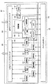
胴体部ユニット2には、図2に示すように、CPU(Central Processing Unit)10、DRAM(Dynamic Random Access Memory)11、フラッシュROM(Read 0nly Memory)12、PC(Personal Computer)カードインターフェース回路13及び信号処理回路14が内部バス15を介して相互に接続されることにより形成されたコントロール部16と、このロボット装置1の動力源としてのバッテリ17とが収納されている。また、胴体部ユニット2には、ロボット装置1の向きや動きの加速度を検出するための角速度センサ18及び加速度センサ19なども収納されている。
【0018】
また、頭部ユニット4には、外部の状況を撮像するためのCCD(Charge Coupled Device)カメラ20と、使用者からの「撫でる」や「叩く」といった物理的な働きかけにより受けた圧力を検出するためのタッチセンサ21と、前方に位置する物体までの距離を測定するための距離センサ22と、外部音を集音するためのマイクロホン23と、鳴き声等の音声を出力するためのスピーカ24と、ロボット装置1の「目」に相当するLED(Light Emitting Diode)(図示せず)となどがそれぞれ所定位置に配置されている。ここで、CCDカメラ20は、顔識別において顔画像を撮像する撮像手段を構成する。
【0019】
さらに、各脚部ユニット3A〜3Dの関節部分や各脚部ユニット3A〜3D及び胴体部ユニット2の各連結部分、頭部ユニット4及び胴体部ユニット2の連結部分、並びに尻尾部ユニット5の尻尾5Aの連結部分などにはそれぞれ自由度数分のアクチュエータ251〜25n及びポテンショメータ261〜26nが配設されている。例えば、アクチュエータ251〜25nはサーボモータを構成として有している。サーボモータの駆動により、脚部ユニット3A〜3Dが制御されて、目標の姿勢或いは動作に遷移する。
【0020】
そして、これら角速度センサ18、加速度センサ19、タッチセンサ21、距離センサ22、マイクロホン23、スピーカ24及び各ポテンショメータ261〜26nなどの各種センサ並びにLED及び各アクチュエータ251 〜25nは、それぞれ対応するハブ271〜27nを介してコントロール部16の信号処理回路14と接続され、CCDカメラ20及びバッテリ17は、それぞれ信号処理回路14と直接接続されている。
【0021】
信号処理回路l4は、上述の各センサから供給されるセンサデータや画像データ及び音声データを順次取り込み、これらをそれぞれ内部バス15を介してDRAM11内の所定位置に順次格納する。また信号処理回路14は、これと共にバッテリ17から供給されるバッテリ残量を表すバッテリ残量データを順次取り込み、これをDRAM11内の所定位置に格納する。
【0022】
このようにしてDRAM11に格納された各センサデータ、画像データ、音声データ及びバッテリ残量データは、この後CPU10がこのロボット装置1の動作制御を行う際に利用される。
【0023】
実際上CPU10は、ロボット装置1の電源が投入された初期時、胴体部ユニット2の図示しないPCカードスロットに装填されたメモリカード28又はフラッシュROM12に格納された制御プログラムをPCカードインターフェース回路13を介して又は直接読み出し、これをDRAM11に格納する。
【0024】
また、CPU10は、この後上述のように信号処理回路14よりDRAM11に順次格納される各センサデータ、画像データ、音声データ及びバッテリ残量データに基づいて自己及び周囲の状況や、使用者からの指示及び働きかけの有無などを判断する。
【0025】
さらに、CPU10は、この判断結果及びDRAM11に格納した制御プログラムに基づいて続く行動を決定すると共に、当該決定結果に基づいて必要なアクチュエータ251〜25nを駆動させることにより、頭部ユニット4を上下左右に振らせたり、尻尾部ユニット5の尻尾5Aを動かせたり、各脚部ユニット3A〜3Dを駆動させて歩行させるなどの行動を行わせる。
【0026】
また、この際CPU10は、必要に応じて音声データを生成し、これを信号処理回路14を介して音声信号としてスピーカ24に与えることにより当該音声信号に基づく音声を外部に出力させたり、上述のLEDを点灯、消灯又は点滅させる。
【0027】
このようにしてこのロボット装置1においては、自己及び周囲の状況や、使用者からの指示及び働きかけに応じて自律的に行動し得るようになされている。
【0028】
(2)制御プログラムのソフトウェア構成
ここで、ロボット装置1における上述の制御プログラムのソフトウェア構成は、図3に示すようになる。この図3において、デバイス・ドライバ・レイヤ30は、この制御プログラムの最下位層に位置し、複数のデバイス・ドライバからなるデバイス・ドライバ・セット31から構成されている。この場合、各デバイス・ドライバは、CCDカメラ20(図2)やタイマ等の通常のコンピュータで用いられるハードウェアに直接アクセスするごとを許されたオブジェクトであり、対応するハードウェアからの割り込みを受けて処理を行う。
【0029】
また、ロボティック・サーバ・オブジェクト32は、デバイス・ドライバ・レイヤ30の最下位層に位置し、例えば上述の各種センサやアクチュエータ251〜25n等のハードウェアにアクセスするためのインターフェースを提供するソフトウェア群でなるバーチャル・ロボット33と、電源の切換えなどを管理するソフトウェア群でなるバワーマネージャ34と、他の種々のデバイス・ドライバを管理するソフトウェア群でなるデバイス・ドライバ・マネージャ35と、ロボット装置1の機構を管理するソフトウェア群でなるデザインド・ロボット36とから構成されている。
【0030】
マネージャ・オブジェクト37は、オブジェクト・マネージャ38及びサービス・マネージャ39から構成されている。オブジェクト・マネージャ38は、ロボティック・サーバ・オブジェクト32、ミドル・ウェア・レイヤ40、及びアプリケーション・レイヤ41に含まれる各ソフトウェア群の起動や終了を管理するソフトウェア群であり、サービス・マネージャ39は、メモリカード28(図2)に格納されたコネクションファイルに記述されている各オブジェクト間の接続情報に基づいて各オブジェクトの接続を管理するソフトウェア群である。
【0031】
ミドル・ウェア・レイヤ40は、ロボティック・サーバ・オブジェクト32の上位層に位置し、画像処理や音声処理などのこのロボット装置1の基本的な機能を提供するソフトウェア群から構成されている。また、アプリケーション・レイヤ41は、ミドル・ウェア・レイヤ40の上位層に位置し、当該ミドル・ウェア・レイヤ40を構成する各ソフトウェア群によって処理された処理結果に基づいてロボット装置1の行動を決定するためのソフトウェア群から構成されている。
【0032】
なお、ミドル・ウェア・レイヤ40及びアプリケーション・レイヤ41の具体なソフトウェア構成をそれぞれ図4に示す。
【0033】
ミドル・ウェア・レイヤ40は、図4に示すように、騒音検出用、温度検出用、明るさ検出用、音階認識用、距離検出用、姿勢検出用、タッチセンサ用、動き検出用及び色認識用の各信号処理モジュール50〜58並びに入力セマンティクスコンバータモジュール59などを有する認識系60と、出力セマンティクスコンバータモジュール68並びに姿勢管理用、トラッキング用、モーション再生用、歩行用、転倒復帰用、LED点灯用及び音再生用の各信号処理モジュール61〜67などを有する出力系69とから構成されている。
【0034】
認識系60の各信号処理モジュール50〜58は、ロボティック・サーバ・オブジェクト32のバーチャル・ロボット33によりDRAM11(図2)から読み出される各センサデータや画像データ及び音声データのうちの対応するデータを取り込み、当該データに基づいて所定の処理を施して、処理結果を入力セマンティクスコンバータモジュール59に与える。ここで、例えば、バーチャル・ロボット33は、所定の通信規約によって、信号の授受或いは変換をする部分として構成されている。
【0035】
入力セマンティクスコンバータモジュール59は、これら各信号処理モジュール50〜58から与えられる処理結果に基づいて、「うるさい」、「暑い」、「明るい」、「ボールを検出した」、「転倒を検出した」、「撫でられた」、「叩かれた」、「ドミソの音階が聞こえた」、「動く物体を検出した」又は「障害物を検出した」などの自己及び周囲の状況や、使用者からの指令及び働きかけを認識し、認識結果をアプリケーション・レイヤ41(図2)に出力する。
【0036】
アプリケーション・レイヤ4lは、図5に示すように、行動モデルライブラリ70、行動切換えモジュール71、学習モジュール72、感情モデル73及び本能モデル74の5つのモジュールから構成されている。
【0037】
行動モデルライブラリ70には、図6に示すように、「バッテリ残量が少なくなった場合」、「転倒復帰する」、「障害物を回避する場合」、「感情を表現する場合」、「ボールを検出した場合」などの予め選択されたいくつかの条件項目にそれぞれ対応させて、それぞれ独立した行動モデル701〜70nが設けられている。
【0038】
そして、これら行動モデル701〜70nは、それぞれ入力セマンティクスコンバータモジュール59から認識結果が与えられたときや、最後の認識結果が与えられてから一定時間が経過したときなどに、必要に応じて後述のように感情モデル73に保持されている対応する情動のパラメータ値や、本能モデル74に保持されている対応する欲求のパラメータ値を参照しながら続く行動をそれぞれ決定し、決定結果を行動切換えモジュール71に出力する。
【0039】
なお、この実施の形態の場合、各行動モデル701〜70nは、次の行動を決定する手法として、図7に示すような1つのノード(状態)NODE0〜NODEnから他のどのノードNODE0〜NODEnに遷移するかを各ノードNODE0〜NODEnに間を接続するアークARC1〜ARCnに対してそれぞれ設定された遷移確率P1〜Pnに基づいて確率的に決定する有限確率オートマトンと呼ばれるアルゴリズムを用いる。
【0040】
具体的に、各行動モデル701〜70nは、それぞれ自己の行動モデル701〜70nを形成するノードNODE0〜NODEnにそれぞれ対応させて、これらノードNODE0〜NODEnごとに図8に示すような状態遷移表80を有している。
【0041】
この状態遷移表80では、そのノードNODE0〜NODEnにおいて遷移条件とする入力イベント(認識結果)が「入力イベント名」の行に優先順に列記され、その遷移条件についてのさらなる条件が「データ名」及び「データ範囲」の行における対応する列に記述されている。
【0042】
したがって、図8の状態遷移表80で表されるノードNODE100では、「ボールを検出(BALL)」という認識結果が与えられた場合に、当該認識結果と共に与えられるそのボールの「大きさ(SIZE)」が「0から1000」の範囲であることや、「障害物を検出(OBSTACLE)」という認識結果が与えられた場合に、当該認識結果と共に与えられるその障害物までの「距離(DISTANCE)」が「0から100」の範囲であることが他のノードに遷移するための条件となっている。
【0043】
また、このノードNODE100では、認識結果の入力がない場合においても、行動モデル701〜70nが周期的に参照する感情モデル73及び本能モデル74にそれぞれ保持された各情動及び各欲求のパラメータ値のうち、感情モデル73に保持された「喜び(JOY)」、「驚き(SURPRISE)」若しくは「悲しみ(SUDNESS)」のいずれかのパラメータ値が「50から100」の範囲であるときには他のノードに遷移することができるようになっている。
【0044】
また、状態遷移表80では、「他のノードヘの遷移確率」の欄における「遷移先ノード」の列にそのノードNODE0〜 NODEnから遷移できるノード名が列記されていると共に、「入力イベント名」、「データ値」及び「データの範囲」の行に記述された全ての条件が揃ったときに遷移できる他の各ノードNODE0〜NODEnへの遷移確率が「他のノードヘの遷移確率」の欄内の対応する箇所にそれぞれ記述され、そのノードNODE0〜NODEnに遷移する際に出力すべき行動が「他のノードヘの遷移確率」の欄における「出力行動」の行に記述されている。なお、「他のノードヘの遷移確率」の欄における各行の確率の和は100[%]となっている。
【0045】
したがって、図8の状態遷移表80で表されるノードNODE100では、例えば「ボールを検出(BALL)」し、そのボールの「SIZE(大きさ)」が「0から1000」の範囲であるという認識結果が与えられた場合には、「30[%]」の確率で「ノードNODE120(node 120)」に遷移でき、そのとき「ACTION1」の行動が出力されることとなる。
【0046】
各行動モデル701〜70nは、それぞれこのような状態遷移表80として記述されたノードNODE0〜 NODEnがいくつも繋がるようにして構成されており、入力セマンティクスコンバータモジュール59から認識結果が与えられたときなどに、対応するノードNODE0〜NODEnの状態遷移表を利用して確率的に次の行動を決定し、決定結果を行動切換えモジュール71に出力するようになされている。
【0047】
図5に示す行動切換えモジュール71は、行動モデルライブラリ70の各行動モデル701〜70nからそれぞれ出力される行動のうち、予め定められた優先順位の高い行動モデル701〜70nから出力された行動を選択し、当該行動を実行すべき旨のコマンド(以下、これを行動コマンドという。)をミドル・ウェア・レイヤ40の出力セマンティクスコンバータモジュール68に送出する。なお、この実施の形態においては、図6において下側に表記された行動モデル701〜70nほど優先順位が高く設定されている。
【0048】
また、行動切換えモジュール71は、行動完了後に出力セマンティクスコンバータモジュール68から与えられる行動完了情報に基づいて、その行動が完了したことを学習モジュール72、感情モデル73及び本能モデル74に通知する。
【0049】
一方、学習モジュール72は、入力セマンティクスコンバータモジュール59から与えられる認識結果のうち、「叩かれた」や「撫でられた」など、使用者からの働きかけとして受けた教示の認識結果を入力する。
【0050】
そして、学習モジュール72は、この認識結果及び行動切換えモジュール71からの通知に基づいて、「叩かれた(叱られた)」ときにはその行動の発現確率を低下させ、「撫でられた(誉められた)」ときにはその行動の発現確率を上昇させるように、行動モデルライブラリ70における対応する行動モデル701〜70nの対応する遷移確率を変更する。
【0051】
他方、感情モデル73は、「喜び(joy)」、「悲しみ(sadness)」、「怒り(anger)」、「驚き(surprise)」、「嫌悪(disgust)」及び「恐れ(fear)」の合計6つの情動について、各情動ごとにその情動の強さを表すパラメータを保持している。そして、感情モデル73は、これら各情動のパラメータ値を、それぞれ入力セマンティクスコンバータモジュール59から与えられる「叩かれた」及び「撫でられた」などの特定の認識結果と、経過時間及び行動切換えモジュール71からの通知となどに基づいて周期的に更新する。
【0052】
具体的には、感情モデル73は、入力セマンティクスコンバータモジュール59から与えられる認識結果と、そのときのロボット装置1の行動と、前回更新してからの経過時間となどに基づいて所定の演算式により算出されるそのときのその情動の変動量を△E[t]、現在のその情動のパラメータ値をE[t]、その情動の感度を表す係数をkeとして、(1)式によって次の周期におけるその情動のパラメータ値E[t+1]を算出し、これを現在のその情動のパラメータ値E[t]と置き換えるようにしてその情動のパラメータ値を更新する。また、感情モデル73は、これと同様にして全ての情動のパラメータ値を更新する。
【0053】
【数1】

なお、各認識結果や出力セマンティクスコンバータモジュール68からの通知が各情動のパラメータ値の変動量△E[t]にどの程度の影響を与えるかは予め決められており、例えば「叩かれた」といった認識結果は「怒り」の情動のパラメータ値の変動量△E[t]に大きな影響を与え、「撫でられた」といった認識結果は「喜び」の情動のパラメータ値の変動量△E[t]に大きな影響を与えるようになっている。
【0055】
ここで、出力セマンティクスコンバータモジュール68からの通知とは、いわゆる行動のフィードバック情報(行動完了情報)であり、行動の出現結果の情報であり、感情モデル73は、このような情報によっても感情を変化させる。これは、例えば、「吠える」といった行動により怒りの感情レベルが下がるといったようなことである。なお、出力セマンティクスコンバータモジュール68からの通知は、上述した学習モジュール72にも入力されており、学習モジュール72は、その通知に基づいて行動モデル701〜70nの対応する遷移確率を変更する。
【0056】
なお、行動結果のフィードバックは、行動切換えモジュレータ71の出力(感情が付加された行動)によりなされるものであってもよい。
【0057】
一方、本能モデル74は、「運動欲(exercise)」、「愛情欲(affection)」、「食欲(appetite)」及び「好奇心(curiosity)」の互いに独立した4つの欲求について、これら欲求ごとにその欲求の強さを表すパラメータを保持している。そして、本能モデル74は、これらの欲求のパラメータ値を、それぞれ入力セマンティクスコンバータモジュール59から与えられる認識結果や、経過時間及び行動切換えモジュール71からの通知などに基づいて周期的に更新する。
【0058】
具体的には、本能モデル74は、「運動欲」、「愛情欲」及び「好奇心」については、認識結果、経過時間及び出力セマンティクスコンバータモジュール68からの通知などに基づいて所定の演算式により算出されるそのときのその欲求の変動量をΔI[k]、現在のその欲求のパラメータ値をI[k]、その欲求の感度を表す係数kiとして、所定周期で(2)式を用いて次の周期におけるその欲求のパラメータ値I[k+1]を算出し、この演算結果を現在のその欲求のパラメータ値I[k]と置き換えるようにしてその欲求のパラメータ値を更新する。また、本能モデル74は、これと同様にして「食欲」を除く各欲求のパラメータ値を更新する。
【0059】
【数2】
なお、認識結果及び出力セマンティクスコンバータモジュール68からの通知などが各欲求のパラメータ値の変動量△I[k]にどの程度の影響を与えるかは予め決められており、例えば出力セマンティクスコンバータモジュール68からの通知は、「疲れ」のパラメータ値の変動量△I[k]に大きな影響を与えるようになっている。
【0061】
なお、本実施の形態においては、各情動及び各欲求(本能)のパラメータ値がそれぞれ0から100までの範囲で変動するように規制されており、また係数ke、kiの値も各情動及び各欲求ごとに個別に設定されている。
【0062】
一方、ミドル・ウェア・レイヤ40の出力セマンティクスコンバータモジュール68は、図4に示すように、上述のようにしてアプリケーション・レイヤ41の行動切換えモジュール71から与えられる「前進」、「喜ぶ」、「鳴く」又は「トラッキング(ボールを追いかける)」といった抽象的な行動コマンドを出力系69の対応する信号処理モジュール61〜67に与える。
【0063】
そしてこれら信号処理モジュール61〜67は、行動コマンドが与えられると当該行動コマンドに基づいて、その行動を行うために対応するアクチュエータ251〜25n(図2)に与えるべきサーボ指令値や、スピーカ24(図2)から出力する音の音声データ及び又は「目」のLEDに与える駆動データを生成し、これらのデータをロボティック・サーバ・オブジェクト32のバーチャル・ロボット33及び信号処理回路14(図2)を順次介して対応するアクチュエータ251〜25n又はスピーカ24又はLEDに順次送出する。
【0064】
このようにしてロボット装置1においては、制御プログラムに基づいて、自己(内部)及び周囲(外部)の状況や、使用者からの指示及び働きかけに応じた自律的な行動を行うことができるようになされている。
【0065】
(3)ロボット装置による顔識別
(3−1)ロボット装置に適用される顔識別の原理
上述したように、ロボット装置1は、外部からの情報や内部の状態に応じて自律的に行動する。このようなロボット装置1において、従来における顔識別の問題点の解決と、顔識別のタスクを遂行とを、次の3つの技術により実現している。
【0066】
(i)複雑なシーンからの顔の検出
(ii)顔の実時間トラッキング
(iii)顔の識別
顔の検出手法は、対象物の識別に色、動き及びパターンを使うものに大別できるが、複雑なシーンの中から精度良く顔を切り出すためには顔のパターンを使うのが最も高性能である。しかしながら、シーン全体にわたり全てのスケールの顔を探索するのは、非常に処理が重いため、従来より、この手法は静止画に対してしか用いられていない。
【0067】
その一方で、実時間で顔を検出するシステムのほとんどは肌色の検出を行っている。しかし、色は照明条件により変化してしまうし、肌色にも人種や個人差があるため、単純な肌色認識のみでは有効な手段となり得ない。
【0068】
そこで、本発明の適用により、検出した顔パターンに含まれる色分布を元に顔の実時間トラッキングを行い、その動的変化に顔検出を適応していく手法を取る。また、推定した色分布から求めた顔領域に対してのみ、顔パターンの探索を行う。これにより、顔検出における演算時間の短縮を図る。
【0069】
さらに、顔の識別には、パターン探索により切り出した顔画像を用いて行う。そして、トラッキングに成功している間は同じ顔の識別結果として扱うことで複数の識別結果から総合的な判断を下すことを可能としている。
【0070】
例えば、図9に示すように、ロボット装置1において行う顔識別のための処理は、(i)複雑なシーンからの顔の検出を、輝度パターンによる顔の検出(顔認識)により行い、(ii)顔の実時間トラッキングを、色による顔の追跡(顔のトラッキング)により行い、そして、(iii)顔の識別を、差分顔を利用した人物識別を行っている。
【0071】
例えば、ロボット装置1におけるこのような各処理は、モジュール或いはオブジェクトとして実現される。すなわち、ロボット装置1は、図9に示すように、顔の追跡モジュールM2、顔の検出モジュールM1及び顔の識別モジュールM3を備える。ここで、顔の追跡モジュールM2は、CCDカメラ20に撮像された画像内で変化する顔を追跡する顔追跡手段として機能し、顔の検出モジュールM1は、顔の追跡モジュールM2による顔の追跡情報に基づいて、撮像手段により撮像された画像内の顔の顔データを検出する顔データ検出手段として機能し、顔の識別モジュールM3は、顔の検出モジュールM1が検出した顔データに基づいて、特定顔を識別する顔識別手段として機能する。
【0072】
ここで、輝度パターンによる顔の検出では、入力画像中から顔を検出(認識)する処理を行う。具体的には、この顔の検出では、サポートベクターマシン(SVM)による顔、非顔の識別を行う。この処理は、通常、環境変化に強く、計算量が多く、姿勢変化に弱いといった特徴がある。ここで、環境変化としては、例えば、周囲の照明の変化が挙げられる。
【0073】
また、色による顔の追跡では、入力画像中の顔を追跡する処理を行う。具体的には、この顔の追跡では、顔の色分布の推定、顔領域の推定を行う。この処理は、通常、環境変化に弱く、計算量が少なく、姿勢変化に強いといった特徴がある。
【0074】
また、人物識別では、上述の顔の検出により認識された顔を特定の顔として識別する処理を行う。具体的には、この人物識別では、目、鼻の位置同定から位置合わせ(モーフィング)を行い、差分顔PCAから同一人物判定を行う。
【0075】
顔識別のシステムでは、以上のような処理を顔識別における各工程として適宜分担させ、相互に補完しあう関係とすることで、精度を高くした顔検出を可能としている。例えば、次のように各処理が補完しあう関係とされている。
【0076】
例えば、図9に示すように、色による顔の追跡では環境変化に弱いが、輝度パターンによる顔の検出では環境に強いことを利用することで補完している。逆に、輝度パターンによる顔の検出では計算量が多く、姿勢変化に弱いが、色による顔の追跡が計算量が少なく、姿勢変化に強いことを利用することが補完している。
【0077】
すなわち、概略すれば次のように言える。もともと計算量が多い処理とされる顔の検出を実時間で行うことは困難である。しかし、所定のタイミングにより一定期間行うとすれば、計算量の負担は軽減される。一方で、各タイミングにおいて入力画像内から顔の位置まで毎回検出したのでは、負担が大きい。
【0078】
そこで、計算量が少なく、姿勢変化に強い処理を利用して、入力画像内の顔の変化を実時間で追跡して、この追跡結果から得られる入力画像内の顔の推定位置についてだけ顔を検出する処理をすることとすれば、顔の位置を特定した状態での顔の検出が可能になる。すなわち、大雑把ではあるが早い処理と、信頼性は高いが遅い処理とを組み合わせて、役割を分担することで、システム全体においては各処理相互間で補完させ、これにより、協調して実時間による顔検出を可能としている。
【0079】
これにより、多くの顔検出結果を短時間で獲得でき、この獲得した顔検出結果に基づいて顔の識別を行い、そのような処理を統計的に処理することで、高精度の顔識別を可能にしている。
【0080】
ロボット装置1は、このような顔識別のシステムにより、シーン中から人間を見つけ出し(顔検出処理)、それを注視し(顔のトラッキング処理)、そこから得られた情報を用いた顔の識別による人物の特定(顔識別処理)に至るまで、全ての処理を自動的に行い、信頼性の高い顔識別を実現している。これによりロボット装置と人間との間で自然なインタラクションが可能になる。以下、顔の検出、顔の追跡及び顔の識別の各処理について具体的に説明する。
【0081】
(3−2)顔の検出
顔の検出については、パターン認識の分野で現在最も学習汎化能力が高いと期待され、注目を集めているサポートベクターマシン(SVM)を用いて顔と非顔の識別を行っている。
【0082】
このような技術としては、B.Sholkopfらの報告(B.Sholkopf, C.Burges, A.Smola,"Advance in Kernel Methods Support Vector Learning", The MIT Press, 1999.)やV.Vapnikの報告(V.Vapnik,"The Nature of Statistical Learning Theory Second Edition", Springer, 1999.)に開示されている技術が挙げられる。本願発明者が行った予備実験の結果からは、この手法が主成分分析やニューラルネットワークを用いる手法と比べ、良好な結果を示すことが分かっている。
【0083】
上述のSVMは、識別関数に線形識別器(パーセプトロン)を用いた学習機械であり、カーネル関数を使うことで非線形空間に拡張することができる。また、識別関数の学習では、クラス間分離のマージンを最大にとるように行われ、その解は二次数理計画法を解くことで得られるため、グローバル解に到達できることを理論的に保証できる。この手法の詳細は次の通りである。入力画像は以下の手順で作成する。
【0084】
先ず、シーンから20×20画素の画像を切り出し、さらに、切り出した画像から顔以外の背景部分を除くために画像の4隅をマスクする。次に、照明による撮像対象物の輝度が変化することを前提として、照明による輝度の勾配を補正して、ヒストグラム平滑化或いはコントラストノーマライゼーションを施す。
【0085】
次に、顔検出に使用する識別関数の学習を行う。学習用のデータとして最初に顔データ、非顔データそれぞれ所定の枚数(例えば、30枚)を用いて、先ず、暫定的な識別関数を得る。それから、このようにして暫定的に得られた識別関数を様々なデータベース上の画像に試して顔の検出を行い、その結果、検出に成功したものを顔データ、失敗したものを非顔データとして学習データに追加し、さらに学習をし直す。
【0086】
例えば、実施例としては、数百枚の画像に対してこの処理を繰り返し、最終的に顔データ389枚、非顔データ576枚を蓄積することができた。また、これらの顔データは全員ほぼ正面を向いていること以外は、人種、表情、髪型、眼鏡、ひげ、照明条件等の違いを含んでおり、これにより、これらの条件に左右されない識別器(例えば、識別モジュール)の学習が期待できる。この結果、得られた所定のサポートベクター、例えば255本のサポートベクターを用いる。
【0087】
以上のような顔の検出は、後で詳述する顔の追跡処理により追従されている画像内の顔部分と推定される領域についてその処理を実施する。すなわち、顔の検出では、顔の追跡処理により限定された検索領域に対してのみ処理を実施する。これにより、信頼性の高い顔の検出処理を短時間で実行可能としている。
【0088】
また、この顔の検出処理は、上述したように、ロボット装置1においてモジュール或いはオブジェクトとして構成される。
【0089】
(3−3)顔の追跡
顔の追跡は、画像中で変化(特に移動)する顔を連続的に追従して、上述の顔の検出において顔の検出のための処理がなされる検索領域を限定するためのものである。特に、自律的に行動するロボット装置1のような場合には、画像内における顔の位置等が変化することから、このような画像内の顔の追従処理は顔識別において効果的に作用する。
【0090】
この顔の追跡では、演算量の少なさ、顔の姿勢変化やオクルージョンに対する強さを考慮し、色領域の追跡をベースに行う。
【0091】
例えば、Yangらの報告(J.Yang, W.Lu, A.Waibel,"Skin-Color Modeling and Adaptation", Technical Report of CMU, CMU-CS-97-146, 1997.)によれば、肌色の分布は輝度で正規化された(3)式及び(4)式により得られる(r,g)平面上で、人物や人種に依らず正規分布に近い分布となることが実験的に知られている。
【0092】
【数3】
【数4】
また、上述のYangらはこの色空間において肌色を表す正規分布のパラメータ推定値を、過去に測定されたデータの線形和の(5)式及び(6)式として表現し、重み係数αj,βjの更新規則を最尤推定により導出している。
【0095】
【数5】
【数6】
ここで、(5)式は平均であり、(6)式は分散である。また、mj,sjはそれぞれ、過去のjステップ前の平均値と分散値である。また、rは最大履歴数である。
【0098】
本手法では、この定式化に基づいて肌色領域の適応的トラッキングを行う。そして、本手法では、色モデルを用いて抽出した画素に対して画像領域上でセグメントを行う。具体的には、色モデルから得られた画素に対して、分布データを取得するための領域を指定する楕円の大きさ、楕円の位置、楕円の傾き等を変化させ、前フレーム中の顔の位置近傍で最も良く適合する楕円を求める。そして、求めた楕円内の画素を現在の肌色の分布データとして取得する。ここで、分布データを取得するための楕円について、その大きさ、位置及び傾きを変化させるのは、例えば、顔までの距離が変化したこと、顔が移動したこと、顔が傾いたこと等に対応するためである。
【0099】
図10には、色空間と画像上位置の両方向からトラッキング制約をかける場合の処理例を示している。顔領域が推定される画像平面における顔領域の色分布を、色空間上に写像する。そして、この色空間において、色の分布推定によるトラッキングを行い、色分布の時間変化を推定して、推定色を使って、画像平面上において顔領域を推定する。
【0100】
このように色空間と画像上位置の両方向からトラッキング制約をかけることで、シーン中に似た色がある場合や照明条件が変動する場合でも比較的安定に顔の肌色を追跡できるようになる。
【0101】
以上のような顔の追跡によって、画像内で移動等する顔を追従することができる。顔の検出では、この顔の追跡によって特定される領域についてその処理を実施しデータを得ている。このように、追従している領域に限定して顔の検出のための処理を実施することができるので、信頼性のある処理内容であっても計算量を少なくして実施することができ、短時間で処理結果を得ることができるようになる。
【0102】
なお、この顔の追跡処理は、上述したように、ロボット装置1においてモジュール或いはオブジェクトとして構成される。
【0103】
(3−4)顔の識別
顔の識別では、上述の顔の検出によって得られた顔データを使用して、特定の顔を識別している。具体的には、この顔の識別では、与えられた2枚の顔画像に対してその画像中の人物が同一人物か、他人であるかの判定をすることで実現している。その判定については、2枚の顔画像の差分画像に基づいて行っている。なお、この顔の識別処理は、上述したように、ロボット装置1においてモジュール或いはオブジェクトとして構成される。
【0104】
具体的には、顔の識別では、先ず、同一人物の2枚の顔画像の差分を学習段階として予め求めており、これを参照して、2枚の顔画像の差分結果から同一人物か別の人物であるかを判定している。
【0105】
その学習段階では、同一人物の2枚の顔画像の差分を求め、同一人物の差分画像群(intra-personal class)を生成し、これを固有値展開することで特徴空間とされるintra-personal classの固有空間を獲得している。例えば、このような学習手法の技術としては、B.Moghaddamらの報告(B. Moghaddam, W.Wahid, A.Pentland, "Beyond Eigenfaces: Probabilistic Matching for Face Recognition", MIT Media Lab. Perceptual Computing Section Technical Report No.443, 1998.)に開示されている技術が挙げられる。
【0106】
そして、このような学習を経て実現される顔識別の処理は次のようになる。先ず、2枚の顔画像の差分を正しく得るためには顔の位置を精度良く求める必要がある。また、顔の中の眼、鼻の位置は人によって異なるため、これらの位置を正規化する必要もある。例えば、ここでは、得られた顔画像に対し固有眼と固有鼻のマッチングを行うことで眼と鼻の位置同定を行い、検出された眼と鼻が定められた位置になるように、アフィン変換で回転・伸縮(モーフィング処理)を行っている。
【0107】
このようなモーフィング操作を経て、入力顔画像とデータベース中の登録顔画像データとされる顔画像との差分を生成する。ここで、データベースとして記憶されている顔画像は、予め登録されているものでもよい。さらに、データベースとして記憶される顔画像については更新或いは新たに蓄積していくこともできる。
【0108】
例えば、ロボット装置1は、画像撮像を撮像するような画像撮像モードにおいて撮像して得た顔画像を、データベースに新たに登録することもできる。例えば、ロボット装置1は、ユーザの命令によって画像を撮像する画像撮像モードを備えており、このようなユーザの命令によって撮像した顔画像をデータベースに新たに登録することもできる。ここで、ユーザによる撮像命令としては、例えば、「顔撮って」といった音声による命令等が挙げられる。このようにすることで、エンターテインメント性を維持しながら、同時に顔画像のデータベースの構築が可能になる。また、例えば、データベース中に予め記憶しておく顔画像としては、各個人について正面を向いた顔画像とする。
【0109】
次に、上述したような差分により得られた差分画像と上述の固有空間とに基づいて、人物を特定する。具体的には、差分画像とintra-personal class空間の距離(distance from feature space,DFFS)及び差分画像をintra-personal空間に投影した点と原点からの距離(distance in feature space,DIFS)を計算する。例えば、同一人物の差分画像がintra-personal class空間内で正規分布をとると仮定すれば、DFFSとDIFSの加算値(DFFS+DIFS)が分布からの距離を表すことになる。そして、この距離が小さいほど同一人物である確率が高いことになる。このような関係を利用して、入力顔画像と最も同一人物確率が高いデータベース画像をシーン中の人物と判断する。例えば、差分値が小さい場合には、差分画像はメリハリなく、いわゆるのっぺりとした画像として得られる。
【0110】
さらに、顔の追跡によるトラッキング情報を利用して上述の確率を時系列的に蓄積している。すなわち、トラッキングに成功している間は各連続シーンごとについてのこのような顔の識別結果を時系列に取得して、このように得られる複数の識別結果が同一人物であるとする制約の下で、それら識別結果を統計的に処理する。この結果、一時的な誤認識があった場合でも、システム全体としては、その影響を受けにくいものとして、信頼の高い顔識別を実現する。
【0111】
例えば、ロボット装置1は、上述したように自律的に行動しており、撮像画像中の顔の向きや大きさは一定であるとは言えない。さらに、データベースとして予め記憶されている顔画像については、略正面を向いた顔の数枚の顔画像を複数人物分用意しているだけである。
【0112】
このような条件の下で、顔の識別をしたのでは、誤った識別結果を得る場合も多い。しかし、トラッキングに成功している間は各連続シーンごとに顔の識別処理を行い、多くの識別結果を取得して、さらにこの識別結果が同一人物のものであるとの制約の下で統計的に処理することにより、一時的に誤った識別結果を得た場合でも、システム全体としては信頼の高い顔識別が可能になる。
【0113】
なお、あらゆる1人の人物についてあらゆるパターンの顔画像を持っていれば良いのだが、そのような横顔のデータを持っていたのでは保持すべきデータ量が膨大なものとなり、非現実である。
【0114】
以上、ロボット装置1に適用される顔の検出、顔の追跡及び顔(人物)の識別として大別される顔識別について説明した。このロボット装置1においては、SVMによる濃淡顔パターンの検出、肌色のモデルと顔領域の適応更新を使ったトラッキング手法、差分顔固有値展開を使った人物識別の3つを組み合わせたものにより、顔識別を行っている。このような顔識別は、実時間、実環境でロバストに動作するトータルな顔識別システムとして実現される。
【0115】
以上のように、計算量が少なく、姿勢変化に強い処理を利用して、入力画像内の顔の変化を実時間で追跡して、この追跡結果から得られる入力画像内の顔の推定位置についてだけ顔を検出する処理をするにより、顔の位置を特定した状態での顔の検出処理が可能になる。一方で、多くの顔検出結果を短時間で獲得できることから、これら顔検出結果に基づいて顔識別を行い統計的に処理することで、高精度での顔識別を可能としている。
【0116】
ロボット装置1は、このような顔識別のシステムにより、シーン中から人間を見つけ出し(顔検出処理)、それを注視し(顔のトラッキング処理)、そこから得られた情報を用いた顔の識別による人物の特定(人物識別処理)に至るまで、全ての処理を自動的に行い、信頼性の高い顔識別を実現する。これによりロボット装置と人間との間で自然なインタラクションが可能になる。以下、実施例について説明する。
【0117】
(3−5)実施例
図11及び図12に例として、顔の検出から顔の識別までの一連の流れを示す。条件としては、例えば、176×120の全シーンから数段階のスケーリングを考慮した顔の検出に5sec程度かけ、色のトラッキングでは50msec周期で実行している場合を例としている。
【0118】
図11に示すように、顔の検出処理では、入力画像G0から顔画像G1を切り出す。そして、顔画像G2のように画像の4隅をマスクして、背景部分を取り除く。一方、人物の特定する顔の識別処理では、モーフィング操作をした顔画像G3を取得する。そして、このような処理は、顔の追跡処理に応じて時系列的に行われるようになる。
【0119】
図12に示すように、顔の識別処理では、上述したようにモーフィング操作により得た顔画像G3について、データベースに予め学習段階で得ている顔画像DG1,DG2,DG3,・・・との差分を得る。これにより、差分の顔画像SD1,SD2,SD3,・・・がそれぞれ得られる。本例では、入力画像内に顔が含まれていた人物は、差分値がP=9.73e−72となったデータベースの第3の顔画像DG3の人物と同一人物である確率が最も高い結果となっている。例えば、本実施例では、同一人物の画像対169枚中123枚(72.8%)が同一人物であると識別され、別人物の画像対5609枚中4093枚(73.0%)が別人物であると識別する結果を得ている。
【0120】
【発明の効果】
本発明に係る顔認識装置は、撮像手段により撮像された画像内で変化する顔を追跡する顔追跡手段と、顔追跡手段による顔の追跡情報に基づいて、撮像手段により撮像された画像内の顔の顔データを検出する顔データ検出手段と、顔データ検出手段が検出した顔データに基づいて、特定顔を識別する顔識別手段とを備えることにより、画像内で変化する顔を追跡しながら当該顔の顔データを検出して、検出した顔データに基づいて、特定顔を特定することができる。
【0121】
また、本発明に係る顔識別方法は、撮像工程にて撮像された画像内で移動する顔を追跡する顔追跡工程と、顔追跡工程による顔の追跡情報に基づいて、撮像工程にて撮像された画像内の顔の顔データを検出する顔データ検出手段と、顔データ検出工程にて検出した顔データに基づいて、特定人物を識別する人物識別工程とを有することにより、画像内で変化する顔を追跡しながら当該顔の顔データを検出して、検出した顔データに基づいて、特定顔を特定することができる。
【図面の簡単な説明】
【図1】本発明の実施の形態であるロボット装置の外観構成を示す斜視図である。
【図2】上述のロボット装置の回路構成を示すブロック図である。
【図3】上述のロボット装置のソフトウェア構成を示すブロック図である。
【図4】上述のロボット装置のソフトウェア構成におけるミドル・ウェア・レイヤの構成を示すブロック図である。
【図5】上述のロボット装置のソフトウェア構成におけるアプリケーション・レイヤの構成を示すブロック図である。
【図6】上述のアプリケーション・レイヤの行動モデルライブラリの構成を示すブロック図である。
【図7】ロボット装置の行動決定のための情報となる有限確率オートマトンを説明するために使用した図である。
【図8】有限確率オートマトンの各ノードに用意された状態遷移表を示す図である。
【図9】顔識別における各処理の説明に使用した図である。
【図10】顔のトラッキングの説明に使用した図である。
【図11】顔検出処理及び顔識別処理において行われる入力画像内から顔が切り出されモーフィングされるまでの処理の説明に使用した図である。
【図12】顔識別処理において行われる顔の差分画像を得る処理の説明に使用した図である。
【符号の説明】
1 ロボット装置、M1 顔の検出モジュール、M2 顔の追跡モジュール、M3 顔の識別モジュール[0001]
BACKGROUND OF THE INVENTION
The present inventionFace identificationMore specifically, the apparatus and the face identification method are described in detail. A robot apparatus that can act autonomously and identify a face.InApplicableFace identification device andThe present invention relates to a face identification method.
[0002]
[Prior art]
Research on face recognition has a benchmark position in verifying pattern recognition theory, and many methods have been developed for a long time. Most of the applications that are supposed to be accurate in a static environment, such as authentication in a security system or person search from a large-scale database, are required.
[0003]
[Problems to be solved by the invention]
By the way, in recent years, a robot apparatus as an entertainment has been provided that has an external shape imitating an animal such as a dog. This robotic device works like an animal by autonomously moving its eyes, legs, etc. according to information from outside (for example, information on the surrounding environment) and internal state (for example, emotional state). The gesture is expressed.
[0004]
With the advent of such robotic devices, there has been a demand for human interface technology that can respond within a certain amount of time in an environment that is somewhat inaccurate and dynamically changes, and one of them is face recognition by robotic devices. It has been. For example, if face identification is used, the robot apparatus can identify a user (owner) from many, and is more entertaining.
[0005]
In the face identification application installed in such a robot apparatus, in addition to the problem of identifying a person in a given scene, it is necessary to solve the following problem.
(1) Since the robot apparatus itself moves, changes in the environment and its diversity must be allowed.
[0006]
(2) Since the positional relationship between the human and the robot apparatus also changes, it is necessary to keep the human in view during the interaction.
[0007]
(3) An image that can be used for identifying a person is selected from a large number of scene images and must be comprehensively judged.
[0008]
(4) It must respond within a certain time.
[0009]
Therefore, the present invention,The above-mentioned various problems can be solvedFace identificationAn object is to provide an apparatus and a face identification method.
[0010]
[Means for Solving the Problems]
In order to solve the above-described problems, a face identification device according to the present invention includes an imaging unit and an image captured by the imaging unit.A face data detecting means for detecting face data based on the luminance pattern, and a color distribution included in the face data detected by the face data detecting means in the captured image.Face tracking means for tracking a changing face, and face identification means for identifying a specific face based on the face data detected by the face data detection means.The face data detection means performs face data detection processing on the estimated face position obtained by tracking the face by the face tracking means, and the face tracking means applies tracking restrictions from both the color space and the position on the image. The face identification means accumulates face identification results using the matching probability with the specific face in time series, and statistically processes the accumulated identification results to perform face identification. Do.
[0011]
This robot apparatus detects face data of the face while tracking a face that changes in the image, and specifies a specific face based on the detected face data.
[0012]
Moreover, in order to solve the above-described problems, the face identification method according to the present invention providesComputerAn imaging process for imaging by an imaging means, and an image captured in the imaging processA face data detection step for detecting face data of the face based on the luminance pattern and a color distribution included in the face data detected in the face data detection step in the captured imageA face tracking step for tracking a changing face, and a person identification step for identifying a specific person based on the face data detected in the face data detection step.In the face data detection step, face data detection processing is performed for the estimated face position obtained by tracking the face in the face tracking step. In the face tracking step, the color space and the position on the image are detected from both directions. Tracking is performed with tracking restrictions, and in the face identification step, face identification results using the matching probability with the specific face are accumulated in time series, and the accumulated identification results are statistically processed. Perform face recognition.
[0013]
Such a face identification method detects face data of the face while tracking a face that changes in the image, and specifies a specific face based on the detected face data.
[0014]
DETAILED DESCRIPTION OF THE INVENTION
Hereinafter, embodiments of the present invention will be described in detail with reference to the drawings. In this embodiment, the present invention is applied to a robot apparatus having an external shape imitating an animal such as a dog. The robotic device can behave like an animal by autonomously moving its eyes, legs, etc. according to information from the outside (for example, information on the surrounding environment) and the internal state (for example, emotional state). Is expressed. And this robot apparatus is comprised as what can identify faces, such as a user (owner).
[0015]
In the embodiment, first, the configuration of the robot apparatus will be described, and then face identification as an application portion of the present invention in the robot apparatus will be described in detail.
[0016]
(1) Configuration of the robot apparatus according to this embodiment
As shown in FIG. 1, for example, a so-called pet robot imitating a “dog” is formed, and
[0017]
As shown in FIG. 2, the
[0018]
Further, the
[0019]
Further, the joint portions of the
[0020]
The
[0021]
The
[0022]
The sensor data, image data, audio data, and battery remaining amount data stored in the DRAM 11 in this way are used when the
[0023]
In practice, when the power of the
[0024]
In addition, the
[0025]
Further, the
[0026]
At this time, the
[0027]
In this way, the
[0028]
(2) Software configuration of control program
Here, the software configuration of the above-described control program in the
[0029]
Further, the
[0030]
The
[0031]
The
[0032]
The specific software configurations of the
[0033]
As shown in FIG. 4, the
[0034]
Each of the
[0035]
Based on the processing result given from each of these
[0036]
As shown in FIG. 5, the application layer 4 l includes five modules: a
[0037]
In the
[0038]
And these
[0039]
In the case of this embodiment, each
[0040]
Specifically, each
[0041]
In this state transition table 80, the node NODE0~ NODEnInput events (recognition results) as transition conditions in are listed in priority order in the “input event name” line, and further conditions for the transition conditions are described in corresponding columns in the “data name” and “data range” lines Has been.
[0042]
Therefore, the node NODE represented by the state transition table 80 in FIG.100Then, when the recognition result “ball detected (BALL)” is given, the “size (SIZE)” of the ball given together with the recognition result is in the range of “0 to 1000”, “ When the recognition result “OBSTACLE” is given, the other node has a “distance” to the obstacle given together with the recognition result within the range of “0 to 100”. It is a condition for transition to.
[0043]
This node NODE100Then, even when no recognition result is input, the
[0044]
Further, in the state transition table 80, the node NODE appears in the “transition destination node” column in the “transition probability to other node” column.0~ NODEnThe node names that can be transitioned from are listed, and each other node NODE that can transition when all the conditions described in the “input event name”, “data value”, and “data range” lines are met.0~ NODEnThe transition probabilities to are respectively described in the corresponding places in the “transition probabilities to other nodes” column, and the node NODE0~ NODEnThe action to be output when transitioning to is described in the “output action” line in the “transition probability to other node” column. The sum of the probabilities of each row in the “transition probability to other node” column is 100 [%].
[0045]
Therefore, the node NODE represented by the state transition table 80 in FIG.100Then, for example, when the “ball is detected (BALL)” and the recognition result that the “SIZE (size)” of the ball is in the range of “0 to 1000” is given, “30 [%]” The probability of “node NODE120(Node 120) ", and the action of"
[0046]
Each
[0047]
The
[0048]
Further, the
[0049]
On the other hand, the
[0050]
Then, based on the recognition result and the notification from the
[0051]
On the other hand, the
[0052]
Specifically, the
[0053]
[Expression 1]
It should be noted that how much each notification result or notification from the output
[0055]
Here, the notification from the output
[0056]
Note that the feedback of the behavior result may be performed by the output of the behavior switching modulator 71 (the behavior to which the emotion is added).
[0057]
On the other hand, the
[0058]
Specifically, the
[0059]
[Expression 2]
Note that how much the recognition result and the notification from the output
[0061]
In the present embodiment, the parameter values of each emotion and each desire (instinct) are regulated so as to fluctuate in the range from 0 to 100, respectively, and the coefficient ke, KiThe value of is also set individually for each emotion and each desire.
[0062]
On the other hand, the output
[0063]
When the action command is given, these
[0064]
In this way, the
[0065]
(3) Face identification by robot device
(3-1) Principle of face identification applied to a robot apparatus
As described above, the
[0066]
(I) Face detection from complex scenes
(Ii) Real-time tracking of faces
(Iii) Face identification
Face detection methods can be broadly classified into those that use colors, movements, and patterns to identify objects, but using the face pattern is the most powerful method for accurately extracting faces from complex scenes. is there. However, searching for faces of all scales throughout the scene is very heavy and so far this technique has been used only for still images.
[0067]
On the other hand, most systems that detect faces in real time detect skin color. However, the color changes depending on the illumination conditions, and the skin color also has races and individual differences. Therefore, simple skin color recognition alone cannot be an effective means.
[0068]
Therefore, by applying the present invention, a method is adopted in which face real-time tracking is performed based on the color distribution included in the detected face pattern, and face detection is adapted to the dynamic change. In addition, the face pattern is searched only for the face area obtained from the estimated color distribution. This shortens the calculation time in face detection.
[0069]
Furthermore, the face is identified using a face image cut out by pattern search. Then, while tracking is successful, it is possible to make a comprehensive judgment from a plurality of identification results by treating it as the identification result of the same face.
[0070]
For example, as shown in FIG. 9, the process for face identification performed in the
[0071]
For example, each process in the
[0072]
Here, in the face detection based on the luminance pattern, processing for detecting (recognizing) the face from the input image is performed. Specifically, in this face detection, a face or non-face is identified by a support vector machine (SVM). This processing is usually characterized by being resistant to environmental changes, requiring a large amount of calculation, and being vulnerable to posture changes. Here, as an environmental change, the change of ambient illumination is mentioned, for example.
[0073]
In the face tracking by color, a process for tracking the face in the input image is performed. Specifically, in this face tracking, estimation of the face color distribution and estimation of the face area are performed. This processing is usually characterized by being weak against environmental changes, having a small amount of calculation, and being strong against posture changes.
[0074]
In the person identification, the face recognized by the above-described face detection is identified as a specific face. Specifically, in this person identification, alignment (morphing) is performed from the eye and nose position identification, and the same person is determined from the differential face PCA.
[0075]
In the face identification system, the processing described above is appropriately shared as each step in face identification, and a mutually complementary relationship is achieved, thereby enabling face detection with high accuracy. For example, each process complements each other as follows.
[0076]
For example, as shown in FIG. 9, the tracking of a face by color is weak against environmental changes, but the detection of a face by a luminance pattern is supplemented by using the fact that it is strong against the environment. On the other hand, the detection of a face using a luminance pattern requires a large amount of calculation and is vulnerable to changes in posture. However, the use of the fact that tracking of a face by color has a small amount of calculation and is strong against posture change is supplemented.
[0077]
In summary, the following can be said. It is difficult to detect in real time a face that is originally a process with a large amount of calculation. However, if it is performed for a certain period at a predetermined timing, the burden of calculation amount is reduced. On the other hand, if it is detected every time from the input image to the face position at each timing, the burden is large.
[0078]
Therefore, using a process that requires a small amount of computation and is resistant to posture changes, the face change in the input image is tracked in real time, and the face is detected only for the estimated face position in the input image obtained from the tracking result. If the detection process is performed, the face can be detected with the face position specified. In other words, by combining rough but fast processing with high reliability but slow processing and sharing roles, the entire system is complemented between each processing, so that in real time in cooperation Face detection is possible.
[0079]
As a result, many face detection results can be acquired in a short time, face identification is performed based on the acquired face detection results, and such processing is processed statistically, thereby enabling highly accurate face identification. I have to.
[0080]
The
[0081]
(3-2) Face detection
As for face detection, a support vector machine (SVM), which is currently expected to have the highest learning generalization ability in the field of pattern recognition, is used to identify a face and a non-face.
[0082]
Such technologies include B. Sholkopf et al. (B. Sholkopf, C. Burges, A. Smola, "Advance in Kernel Methods Support Vector Learning", The MIT Press, 1999.) and V. Vapnik ( V. Vapnik, “The Nature of Statistical Learning Theory Second Edition”, Springer, 1999.). From the results of preliminary experiments conducted by the inventor of the present application, it is known that this method shows better results than methods using principal component analysis and neural networks.
[0083]
The SVM described above is a learning machine that uses a linear classifier (perceptron) as a discriminant function, and can be extended to a nonlinear space by using a kernel function. Further, learning of the discriminant function is performed so as to maximize the margin of separation between classes, and the solution can be obtained by solving the quadratic mathematical programming method, so that it can be theoretically guaranteed that the global solution can be reached. The details of this method are as follows. The input image is created according to the following procedure.
[0084]
First, a 20 × 20 pixel image is cut out from the scene, and further, the four corners of the image are masked in order to remove the background portion other than the face from the cut out image. Next, on the premise that the luminance of the imaging target due to illumination changes, the luminance gradient due to illumination is corrected and histogram smoothing or contrast normalization is performed.
[0085]
Next, the discriminant function used for face detection is learned. First, a predetermined discriminant function is obtained by using a predetermined number (for example, 30) of face data and non-face data as learning data first. Then, the identification function obtained in this way is tried against images on various databases to detect faces, and as a result, those that succeeded as face data and those that failed as non-face data. Add to the learning data and learn again.
[0086]
For example, as an example, this process was repeated for several hundred images, and finally 389 face data and 576 non-face data could be accumulated. In addition, these face data include differences in race, facial expression, hairstyle, glasses, beard, lighting conditions, etc., except that all face data are almost facing the front. Learning (for example, an identification module) can be expected. As a result, the obtained predetermined support vector, for example, 255 support vectors is used.
[0087]
The face detection as described above is performed on a region estimated to be a face portion in the image followed by the face tracking process described in detail later. That is, in face detection, processing is performed only on a search area limited by face tracking processing. This makes it possible to perform highly reliable face detection processing in a short time.
[0088]
The face detection process is configured as a module or an object in the
[0089]
(3-3) Face tracking
The face tracking is to continuously follow a face that changes (especially moves) in an image and to limit a search area in which processing for face detection is performed in the face detection described above. In particular, in the case of the
[0090]
This face tracking is performed based on the tracking of the color area in consideration of the small amount of calculation, the change in the posture of the face and the strength against occlusion.
[0091]
For example, according to a report by Yang et al. (J. Yang, W. Lu, A. Waibel, "Skin-Color Modeling and Adaptation", Technical Report of CMU, CMU-CS-97-146, 1997.) It is experimentally known that the distribution is a distribution close to the normal distribution regardless of the person or race on the (r, g) plane obtained by the expressions (3) and (4) normalized by the luminance. ing.
[0092]
[Equation 3]
[Expression 4]
Moreover, the above-mentioned Yang et al. Express a parameter estimate value of a normal distribution representing skin color in this color space as equations (5) and (6) of linear sums of data measured in the past, and a weighting factor αj, ΒjThe update rule is derived by maximum likelihood estimation.
[0095]
[Equation 5]
[Formula 6]
Here, equation (5) is an average, and equation (6) is variance. Mj, SjAre an average value and a variance value before j steps in the past. R is the maximum number of histories.
[0098]
In this method, the skin color region is adaptively tracked based on this formulation. In this method, a segment is performed on the image region with respect to the pixels extracted using the color model. Specifically, for the pixels obtained from the color model, the size of the ellipse that specifies the area for acquiring the distribution data, the position of the ellipse, the inclination of the ellipse, etc. are changed, and the face in the previous frame is changed. Find the ellipse that best fits near the position. Then, the obtained pixels in the ellipse are acquired as current skin color distribution data. Here, the size, position and inclination of the ellipse for obtaining distribution data are changed, for example, when the distance to the face is changed, the face is moved, the face is inclined, etc. This is to respond.
[0099]
FIG. 10 shows a processing example when the tracking restriction is applied from both the color space and the position on the image. The color distribution of the face area on the image plane where the face area is estimated is mapped onto the color space. Then, in this color space, tracking by color distribution estimation is performed, a time change of the color distribution is estimated, and a face area is estimated on the image plane using the estimated color.
[0100]
By applying tracking restrictions from both the color space and the position on the image in this way, the skin color of the face can be tracked relatively stably even when there are similar colors in the scene or when the illumination conditions vary.
[0101]
By tracking the face as described above, it is possible to follow a face that moves within the image. In face detection, data is obtained by performing the process on the area specified by the tracking of the face. In this way, since the processing for face detection can be performed only in the region that is following, even if the processing content is reliable, the calculation amount can be reduced, The processing result can be obtained in a short time.
[0102]
The face tracking process is configured as a module or an object in the
[0103]
(3-4) Face identification
In face identification, a specific face is identified using face data obtained by the above-described face detection. Specifically, this face identification is realized by determining whether the person in the two face images is the same person or another person. The determination is made based on the difference image between the two face images. The face identification process is configured as a module or an object in the
[0104]
Specifically, in the identification of a face, first, a difference between two face images of the same person is obtained in advance as a learning stage. With reference to this, the difference between the two face images is determined based on whether the same person is identified. It is determined whether it is a person.
[0105]
In the learning stage, the difference between two face images of the same person is calculated, a difference image group (intra-personal class) of the same person is generated, and this is expanded into eigenvalues to be used as a feature space intra-personal class Has acquired the eigenspace. For example, as a technique of such learning method, a report of B. Moghaddam et al. (B. Moghaddam, W. Wahid, A. Pentland, "Beyond Eigenfaces: Probabilistic Matching for Face Recognition", MIT Media Lab. Perceptual Computing Section Technical Report No. 443, 1998.).
[0106]
The face identification process realized through such learning is as follows. First, in order to correctly obtain the difference between two face images, it is necessary to obtain the face position with high accuracy. Moreover, since the positions of the eyes and nose in the face differ depending on the person, it is necessary to normalize these positions. For example, here, the position of the eye and nose is identified by matching the proper eye and proper nose to the obtained face image, and the detected eye and nose are determined to be in a predetermined position. Rotation and expansion / contraction (morphing process)
[0107]
Through such a morphing operation, a difference between the input face image and the face image to be registered face image data in the database is generated. Here, the face image stored as the database may be registered in advance. Furthermore, face images stored as a database can be updated or newly accumulated.
[0108]
For example, the
[0109]
Next, the person is specified based on the difference image obtained by the difference as described above and the eigenspace described above. Specifically, the distance between the difference image and the intra-personal class space (distance from feature space, DFFS) and the distance from the point where the difference image is projected to the intra-personal space and the origin (distance in feature space, DIFS) are calculated. To do. For example, assuming that difference images of the same person have a normal distribution in the intra-personal class space, the added value of DFFS and DIFS (DFFS + DIFS) represents the distance from the distribution. And the probability that it is the same person will become high, so that this distance is small. Using such a relationship, the database image having the highest probability of being the same person as the input face image is determined as a person in the scene. For example, when the difference value is small, the difference image is not sharp and is obtained as a so-called flat image.
[0110]
Further, the above-described probabilities are accumulated in time series using tracking information obtained by tracking a face. In other words, while tracking is successful, such face identification results for each continuous scene are acquired in time series, and a plurality of identification results thus obtained are subject to the same person. Then, the identification results are statistically processed. As a result, even if there is a temporary misrecognition, the system as a whole is less susceptible to the effect and realizes highly reliable face identification.
[0111]
For example, the
[0112]
If a face is identified under such conditions, an incorrect identification result is often obtained. However, while tracking is successful, face identification processing is performed for each continuous scene, many identification results are obtained, and statistically under the restriction that this identification result belongs to the same person. By processing in this way, even when an erroneous identification result is temporarily obtained, the face recognition with high reliability is possible as the entire system.
[0113]
Note that it is only necessary to have face images of every pattern for every single person, but having such profile data makes the amount of data to be retained enormous and unrealistic.
[0114]
In the foregoing, face detection, which is broadly classified as face detection, face tracking, and face (person) identification applied to the
[0115]
As described above, using a process that requires a small amount of computation and is resistant to posture change, the face change in the input image is tracked in real time, and the estimated position of the face in the input image obtained from this tracking result By performing the process of detecting the face only, the face detection process with the face position specified can be performed. On the other hand, since many face detection results can be acquired in a short time, face identification with high accuracy is possible by performing face identification based on these face detection results and performing statistical processing.
[0116]
The
[0117]
(3-5) Examples
As an example, FIG. 11 and FIG. 12 show a series of flows from face detection to face identification. As a condition, for example, it takes about 5 seconds to detect a face taking into account several stages of scaling from all 176 × 120 scenes, and color tracking is performed at a period of 50 msec.
[0118]
As shown in FIG. 11, in the face detection process, the input image G0To face image G1Cut out. And face image G2Mask the four corners of the image to remove the background. On the other hand, in the identification processing of the face specified by the person, the face image G subjected to the morphing operation3To get. Such processing is performed in time series according to the face tracking processing.
[0119]
As shown in FIG. 12, in the face identification process, the face image G obtained by the morphing operation as described above.3Face image DG obtained in the learning stage in advance in the database1, DG2, DG3, ... and the difference is obtained. Thus, the difference face image SD1, SD2, SD3, ... are obtained respectively. In this example, for a person whose face is included in the input image, the difference value is P = 9.73e.-72The third face image DG in the database3The result is the highest probability that the person is the same person. For example, in this embodiment, 123 out of 169 image pairs of the same person (72.8%) are identified as the same person, and 4093 out of 5609 image pairs (73.0%) are different persons. The result of identifying is obtained.
[0120]
【The invention's effect】
According to the present inventionFace recognitionThe apparatus detects face data in the image captured by the imaging unit based on the face tracking unit that tracks a face that changes in the image captured by the imaging unit, and the face tracking information by the face tracking unit. And a face identification unit for identifying a specific face based on the face data detected by the face data detection unit, so that the face data of the face can be obtained while tracking the face that changes in the image. The specific face can be identified based on the detected face data.
[0121]
Further, the face identification method according to the present invention is imaged in the imaging step based on the face tracking step for tracking the moving face in the image captured in the imaging step, and the face tracking information in the face tracking step. It changes in the image by having face data detecting means for detecting the face data of the face in the image and a person identifying step for identifying a specific person based on the face data detected in the face data detecting step. The face data of the face can be detected while tracking the face, and the specific face can be specified based on the detected face data.
[Brief description of the drawings]
FIG. 1 is a perspective view showing an external configuration of a robot apparatus according to an embodiment of the present invention.
FIG. 2 is a block diagram illustrating a circuit configuration of the above-described robot apparatus.
FIG. 3 is a block diagram showing a software configuration of the robot apparatus described above.
FIG. 4 is a block diagram showing a configuration of a middleware layer in the software configuration of the robot apparatus described above.
FIG. 5 is a block diagram showing a configuration of an application layer in the software configuration of the robot apparatus described above.
FIG. 6 is a block diagram showing a configuration of the above-described application layer behavior model library;
FIG. 7 is a diagram used for explaining a finite probability automaton serving as information for determining the behavior of the robot apparatus.
FIG. 8 is a diagram showing a state transition table prepared for each node of a finite probability automaton.
FIG. 9 is a diagram used for explaining each process in face identification;
FIG. 10 is a diagram used for explaining face tracking;
FIG. 11 is a diagram used for explaining processing until a face is cut out from the input image and morphed in face detection processing and face identification processing;
FIG. 12 is a diagram used for explaining processing for obtaining a face difference image performed in face identification processing;
[Explanation of symbols]
1 Robotic device, M1 Face detection module, M2 Face tracking module, M3 Face identification module
Claims (9)
上記撮像手段により撮像された画像内の輝度パターンにより顔の顔データを検出する顔データ検出手段と、
上記顔データ検出手段が検出した顔データに含まれる色分布を元に上記撮像された画像内で変化する顔を追跡する顔追跡手段と、
上記顔データ検出手段が検出した上記顔データに基づいて、特定顔を識別する顔識別手段とを備え、
上記顔データ検出手段は、上記顔追跡手段による顔の追跡によって得られる顔の推定位置について顔データの検出処理を行い、
上記顔追跡手段は、色空間及び画像上位置の両方向からトラッキング制約をかけて追跡を行い、
上記顔識別手段は、上記特定顔との一致確率を用いた顔の識別結果を時系列的に蓄積し、蓄積された識別結果を統計的に処理することにより顔識別を行う
顔識別装置。Imaging means;
Face data detection means for detecting face data of a face based on a luminance pattern in an image picked up by the image pickup means;
Face tracking means for tracking a face that changes in the captured image based on the color distribution included in the face data detected by the face data detection means;
A face identifying means for identifying a specific face based on the face data detected by the face data detecting means,
The face data detection means performs face data detection processing on the estimated face position obtained by tracking the face by the face tracking means,
The face tracking means performs tracking with tracking restrictions from both the color space and the position on the image,
The face identification device accumulates face identification results using the matching probability with the specific face in time series, and performs face identification by statistically processing the accumulated identification results.
上記顔識別手段は、予め得ている全ての登録顔データと上記顔データ検出手段が検出した上記顔データとを差分して得た検出差分値に基づいて特定顔を識別し、上記特徴空間における上記検出差分値に基づいて特定人物を識別する請求項1乃至4のいずれか1項に記載の顔識別装置。A learning means for learning to form a feature space based on the learning difference value by previously obtaining the registered face data and the face data obtained by the face data detecting means, obtaining a learning difference value in advance,
The face identifying means identifies a specific face based on a detection difference value obtained by subtracting all the registered face data obtained in advance and the face data detected by the face data detecting means, in the feature space The face identification device according to claim 1, wherein a specific person is identified based on the detection difference value.
上記撮像手段は、上記動物の目の機能を果たす請求項1乃至6のいずれか1項に記載の顔識別装置Built in a robotic device that looks like an animal and acts autonomously,
The face identification device according to claim 1, wherein the imaging unit performs a function of the eyes of the animal.
撮像手段により撮像する撮像工程と、
上記撮像工程にて撮像された画像内の輝度パターンにより顔の顔データを検出する顔データ検出工程と、
上記顔データ検出工程にて検出した顔データに含まれる色分布を元に上記撮像された画像内で変化する顔を追跡する顔追跡工程と、
上記顔データ検出工程にて検出した上記顔データに基づいて、特定人物を識別する人物識別工程とを実行し、
上記顔データ検出工程では、上記顔追跡工程での顔の追跡によって得られる顔の推定位置について顔データの検出処理を行い、
上記顔追跡工程では、色空間及び画像上位置の両方向からトラッキング制約をかけて追跡を行い、
上記顔識別工程では、上記特定顔との一致確率を用いた顔の識別結果を時系列的に蓄積し、蓄積された識別結果を統計的に処理することにより顔識別を行う
顔識別方法。Computer
An imaging step of imaging by imaging means;
A face data detection step of detecting face data of the face based on a luminance pattern in the image captured in the imaging step;
A face tracking step for tracking a face that changes in the captured image based on a color distribution included in the face data detected in the face data detection step;
Based on the face data detected in the face data detection step, a person identification step for identifying a specific person is performed,
In the face data detection step, face data detection processing is performed for the estimated position of the face obtained by tracking the face in the face tracking step,
In the face tracking step, tracking is performed with tracking restrictions from both the color space and the position on the image,
In the face identification step, a face identification method is performed by accumulating face identification results using the matching probability with the specific face in time series and statistically processing the accumulated identification results.
Priority Applications (4)
| Application Number | Priority Date | Filing Date | Title |
|---|---|---|---|
| JP2000351897A JP4590717B2 (en) | 2000-11-17 | 2000-11-17 | Face identification device and face identification method |
| US10/181,279 US7200249B2 (en) | 2000-11-17 | 2001-11-19 | Robot device and face identifying method, and image identifying device and image identifying method |
| PCT/JP2001/010101 WO2002041254A1 (en) | 2000-11-17 | 2001-11-19 | Robot device and face identifying method, and image identifying device and image identifying method |
| US11/656,115 US7317817B2 (en) | 2000-11-17 | 2007-01-22 | Robot apparatus, face identification method, image discriminating method and apparatus |
Applications Claiming Priority (1)
| Application Number | Priority Date | Filing Date | Title |
|---|---|---|---|
| JP2000351897A JP4590717B2 (en) | 2000-11-17 | 2000-11-17 | Face identification device and face identification method |
Publications (3)
| Publication Number | Publication Date |
|---|---|
| JP2002157596A JP2002157596A (en) | 2002-05-31 |
| JP2002157596A5 JP2002157596A5 (en) | 2007-04-26 |
| JP4590717B2 true JP4590717B2 (en) | 2010-12-01 |
Family
ID=18824869
Family Applications (1)
| Application Number | Title | Priority Date | Filing Date |
|---|---|---|---|
| JP2000351897A Expired - Fee Related JP4590717B2 (en) | 2000-11-17 | 2000-11-17 | Face identification device and face identification method |
Country Status (3)
| Country | Link |
|---|---|
| US (2) | US7200249B2 (en) |
| JP (1) | JP4590717B2 (en) |
| WO (1) | WO2002041254A1 (en) |
Families Citing this family (98)
| Publication number | Priority date | Publication date | Assignee | Title |
|---|---|---|---|---|
| JP2004001162A (en) * | 2002-03-28 | 2004-01-08 | Fuji Photo Film Co Ltd | Pet robot charging system, receiving arrangement, robot, and robot system |
| JP3996015B2 (en) * | 2002-08-09 | 2007-10-24 | 本田技研工業株式会社 | Posture recognition device and autonomous robot |
| GB2395779A (en) * | 2002-11-29 | 2004-06-02 | Sony Uk Ltd | Face detection |
| JP2004298988A (en) * | 2003-03-31 | 2004-10-28 | Honda Motor Co Ltd | Picture image transmission device of mobile robot |
| US7565030B2 (en) | 2003-06-26 | 2009-07-21 | Fotonation Vision Limited | Detecting orientation of digital images using face detection information |
| US8363951B2 (en) * | 2007-03-05 | 2013-01-29 | DigitalOptics Corporation Europe Limited | Face recognition training method and apparatus |
| US9692964B2 (en) | 2003-06-26 | 2017-06-27 | Fotonation Limited | Modification of post-viewing parameters for digital images using image region or feature information |
| US8494286B2 (en) | 2008-02-05 | 2013-07-23 | DigitalOptics Corporation Europe Limited | Face detection in mid-shot digital images |
| US8682097B2 (en) | 2006-02-14 | 2014-03-25 | DigitalOptics Corporation Europe Limited | Digital image enhancement with reference images |
| US8948468B2 (en) | 2003-06-26 | 2015-02-03 | Fotonation Limited | Modification of viewing parameters for digital images using face detection information |
| US8330831B2 (en) | 2003-08-05 | 2012-12-11 | DigitalOptics Corporation Europe Limited | Method of gathering visual meta data using a reference image |
| US7574016B2 (en) | 2003-06-26 | 2009-08-11 | Fotonation Vision Limited | Digital image processing using face detection information |
| US9129381B2 (en) | 2003-06-26 | 2015-09-08 | Fotonation Limited | Modification of post-viewing parameters for digital images using image region or feature information |
| US8553949B2 (en) * | 2004-01-22 | 2013-10-08 | DigitalOptics Corporation Europe Limited | Classification and organization of consumer digital images using workflow, and face detection and recognition |
| US7844076B2 (en) | 2003-06-26 | 2010-11-30 | Fotonation Vision Limited | Digital image processing using face detection and skin tone information |
| US8155397B2 (en) | 2007-09-26 | 2012-04-10 | DigitalOptics Corporation Europe Limited | Face tracking in a camera processor |
| US8593542B2 (en) | 2005-12-27 | 2013-11-26 | DigitalOptics Corporation Europe Limited | Foreground/background separation using reference images |
| US7620218B2 (en) | 2006-08-11 | 2009-11-17 | Fotonation Ireland Limited | Real-time face tracking with reference images |
| US8896725B2 (en) | 2007-06-21 | 2014-11-25 | Fotonation Limited | Image capture device with contemporaneous reference image capture mechanism |
| US7269292B2 (en) * | 2003-06-26 | 2007-09-11 | Fotonation Vision Limited | Digital image adjustable compression and resolution using face detection information |
| US8498452B2 (en) | 2003-06-26 | 2013-07-30 | DigitalOptics Corporation Europe Limited | Digital image processing using face detection information |
| US8989453B2 (en) | 2003-06-26 | 2015-03-24 | Fotonation Limited | Digital image processing using face detection information |
| US7792335B2 (en) | 2006-02-24 | 2010-09-07 | Fotonation Vision Limited | Method and apparatus for selective disqualification of digital images |
| US7471846B2 (en) | 2003-06-26 | 2008-12-30 | Fotonation Vision Limited | Perfecting the effect of flash within an image acquisition devices using face detection |
| US7792970B2 (en) | 2005-06-17 | 2010-09-07 | Fotonation Vision Limited | Method for establishing a paired connection between media devices |
| US7440593B1 (en) * | 2003-06-26 | 2008-10-21 | Fotonation Vision Limited | Method of improving orientation and color balance of digital images using face detection information |
| JP4048492B2 (en) * | 2003-07-03 | 2008-02-20 | ソニー株式会社 | Spoken dialogue apparatus and method, and robot apparatus |
| JP4470434B2 (en) | 2003-10-06 | 2010-06-02 | 富士ゼロックス株式会社 | Motion identification device and object posture identification device |
| JP2005122351A (en) * | 2003-10-15 | 2005-05-12 | Seiko Epson Corp | Method, system and program for searching for face image candidate area |
| JP2005134966A (en) * | 2003-10-28 | 2005-05-26 | Seiko Epson Corp | Face image candidate area retrieval method, retrieval system and retrieval program |
| US7564994B1 (en) | 2004-01-22 | 2009-07-21 | Fotonation Vision Limited | Classification system for consumer digital images using automatic workflow and face detection and recognition |
| JP4373828B2 (en) * | 2004-03-22 | 2009-11-25 | 富士フイルム株式会社 | Specific area detection method, specific area detection apparatus, and program |
| US7894637B2 (en) | 2004-05-21 | 2011-02-22 | Asahi Kasei Corporation | Device, program, and method for classifying behavior content of an object person |
| US8320641B2 (en) | 2004-10-28 | 2012-11-27 | DigitalOptics Corporation Europe Limited | Method and apparatus for red-eye detection using preview or other reference images |
| US7715597B2 (en) | 2004-12-29 | 2010-05-11 | Fotonation Ireland Limited | Method and component for image recognition |
| US8503800B2 (en) | 2007-03-05 | 2013-08-06 | DigitalOptics Corporation Europe Limited | Illumination detection using classifier chains |
| US7315631B1 (en) | 2006-08-11 | 2008-01-01 | Fotonation Vision Limited | Real-time face tracking in a digital image acquisition device |
| US8488023B2 (en) * | 2009-05-20 | 2013-07-16 | DigitalOptics Corporation Europe Limited | Identifying facial expressions in acquired digital images |
| JP4586548B2 (en) * | 2005-01-26 | 2010-11-24 | ソニー株式会社 | Object detection apparatus and object detection method |
| CN100458817C (en) * | 2005-07-21 | 2009-02-04 | 欧姆龙株式会社 | Monitoring apparatus |
| JP4750520B2 (en) * | 2005-09-21 | 2011-08-17 | 富士フイルム株式会社 | Human image correction apparatus and method |
| JP2007121654A (en) * | 2005-10-27 | 2007-05-17 | Eastman Kodak Co | Photographing device |
| US7804983B2 (en) | 2006-02-24 | 2010-09-28 | Fotonation Vision Limited | Digital image acquisition control and correction method and apparatus |
| EP2033142B1 (en) | 2006-06-12 | 2011-01-26 | Tessera Technologies Ireland Limited | Advances in extending the aam techniques from grayscale to color images |
| WO2008001492A1 (en) * | 2006-06-28 | 2008-01-03 | Nec Corporation | Robot, robot control method and robot control program |
| EP2050043A2 (en) * | 2006-08-02 | 2009-04-22 | Fotonation Vision Limited | Face recognition with combined pca-based datasets |
| US7403643B2 (en) | 2006-08-11 | 2008-07-22 | Fotonation Vision Limited | Real-time face tracking in a digital image acquisition device |
| US7916897B2 (en) | 2006-08-11 | 2011-03-29 | Tessera Technologies Ireland Limited | Face tracking for controlling imaging parameters |
| US8055067B2 (en) | 2007-01-18 | 2011-11-08 | DigitalOptics Corporation Europe Limited | Color segmentation |
| EP2115662B1 (en) * | 2007-02-28 | 2010-06-23 | Fotonation Vision Limited | Separating directional lighting variability in statistical face modelling based on texture space decomposition |
| JP4970557B2 (en) * | 2007-03-05 | 2012-07-11 | デジタルオプティックス・コーポレイション・ヨーロッパ・リミテッド | Face search and detection in digital image capture device |
| WO2008109622A1 (en) | 2007-03-05 | 2008-09-12 | Fotonation Vision Limited | Face categorization and annotation of a mobile phone contact list |
| JP4389956B2 (en) * | 2007-04-04 | 2009-12-24 | ソニー株式会社 | Face recognition device, face recognition method, and computer program |
| KR100886557B1 (en) * | 2007-05-03 | 2009-03-02 | 삼성전자주식회사 | System and method for face recognition based on adaptive learning |
| US7916971B2 (en) * | 2007-05-24 | 2011-03-29 | Tessera Technologies Ireland Limited | Image processing method and apparatus |
| KR100901272B1 (en) | 2007-08-24 | 2009-06-09 | 한국전자통신연구원 | System and method for generating an initial template |
| CN104200145B (en) | 2007-09-24 | 2020-10-27 | 苹果公司 | Embedded verification system in electronic device |
| US8600120B2 (en) * | 2008-01-03 | 2013-12-03 | Apple Inc. | Personal computing device control using face detection and recognition |
| US8750578B2 (en) * | 2008-01-29 | 2014-06-10 | DigitalOptics Corporation Europe Limited | Detecting facial expressions in digital images |
| US8265474B2 (en) * | 2008-03-19 | 2012-09-11 | Fujinon Corporation | Autofocus system |
| US7855737B2 (en) | 2008-03-26 | 2010-12-21 | Fotonation Ireland Limited | Method of making a digital camera image of a scene including the camera user |
| JP2014116033A (en) * | 2008-06-16 | 2014-06-26 | Canon Inc | Personal authentication device, personal authentication method, camera, program, and storage medium |
| JP2010027035A (en) | 2008-06-16 | 2010-02-04 | Canon Inc | Personal authentication equipment and personal authentication method |
| US8565922B2 (en) * | 2008-06-27 | 2013-10-22 | Intuitive Automata Inc. | Apparatus and method for assisting in achieving desired behavior patterns |
| JP2010033305A (en) * | 2008-07-29 | 2010-02-12 | Hitachi Ltd | Image information processing method and device |
| WO2010012448A2 (en) | 2008-07-30 | 2010-02-04 | Fotonation Ireland Limited | Automatic face and skin beautification using face detection |
| WO2010058678A1 (en) * | 2008-11-19 | 2010-05-27 | シャープ株式会社 | Specified color area demarcation circuit, detection circuit, and image processing apparatus using same |
| WO2010063463A2 (en) * | 2008-12-05 | 2010-06-10 | Fotonation Ireland Limited | Face recognition using face tracker classifier data |
| US20100186234A1 (en) | 2009-01-28 | 2010-07-29 | Yehuda Binder | Electric shaver with imaging capability |
| KR20100086262A (en) * | 2009-01-22 | 2010-07-30 | 삼성전자주식회사 | Robot and control method thereof |
| US20100295782A1 (en) | 2009-05-21 | 2010-11-25 | Yehuda Binder | System and method for control based on face ore hand gesture detection |
| US8379917B2 (en) | 2009-10-02 | 2013-02-19 | DigitalOptics Corporation Europe Limited | Face recognition performance using additional image features |
| CN101859374A (en) * | 2010-05-20 | 2010-10-13 | 上海洪剑智能科技有限公司 | Distributed face identification system and identification method thereof |
| US8326001B2 (en) * | 2010-06-29 | 2012-12-04 | Apple Inc. | Low threshold face recognition |
| US8824747B2 (en) | 2010-06-29 | 2014-09-02 | Apple Inc. | Skin-tone filtering |
| CN102402680B (en) * | 2010-09-13 | 2014-07-30 | 株式会社理光 | Hand and indication point positioning method and gesture confirming method in man-machine interactive system |
| US9002322B2 (en) | 2011-09-29 | 2015-04-07 | Apple Inc. | Authentication with secondary approver |
| US20130085602A1 (en) * | 2011-10-04 | 2013-04-04 | Hei Tao Fung | Office Robot System |
| US9633186B2 (en) | 2012-04-23 | 2017-04-25 | Apple Inc. | Systems and methods for controlling output of content based on human recognition data detection |
| CN103577797B (en) * | 2012-08-03 | 2016-08-24 | 华晶科技股份有限公司 | Image recognition system and image recognition method thereof |
| US9898642B2 (en) | 2013-09-09 | 2018-02-20 | Apple Inc. | Device, method, and graphical user interface for manipulating user interfaces based on fingerprint sensor inputs |
| JP2015088096A (en) | 2013-11-01 | 2015-05-07 | 株式会社ソニー・コンピュータエンタテインメント | Information processor and information processing method |
| JP6025690B2 (en) | 2013-11-01 | 2016-11-16 | ソニー株式会社 | Information processing apparatus and information processing method |
| JP6147198B2 (en) * | 2014-01-10 | 2017-06-14 | 富士ソフト株式会社 | robot |
| US9483763B2 (en) | 2014-05-29 | 2016-11-01 | Apple Inc. | User interface for payments |
| WO2016136214A1 (en) * | 2015-02-27 | 2016-09-01 | 日本電気株式会社 | Identifier learning device, remaining object detection system, identifier learning method, remaining object detection method, and program recording medium |
| US10674953B2 (en) * | 2016-04-20 | 2020-06-09 | Welch Allyn, Inc. | Skin feature imaging system |
| CN106488197A (en) * | 2016-12-26 | 2017-03-08 | 旗瀚科技有限公司 | A kind of intelligent person recognition robot |
| CN106791681A (en) * | 2016-12-31 | 2017-05-31 | 深圳市优必选科技有限公司 | Video monitoring and face identification method, apparatus and system |
| WO2018213623A1 (en) * | 2017-05-17 | 2018-11-22 | Sphero, Inc. | Computer vision robot control |
| JP6736686B1 (en) | 2017-09-09 | 2020-08-05 | アップル インコーポレイテッドApple Inc. | Implementation of biometrics |
| KR102185854B1 (en) | 2017-09-09 | 2020-12-02 | 애플 인크. | Implementation of biometric authentication |
| US10796185B2 (en) * | 2017-11-03 | 2020-10-06 | Facebook, Inc. | Dynamic graceful degradation of augmented-reality effects |
| US10828790B2 (en) | 2017-11-16 | 2020-11-10 | Google Llc | Component feature detector for robotic systems |
| US11170085B2 (en) | 2018-06-03 | 2021-11-09 | Apple Inc. | Implementation of biometric authentication |
| US11100349B2 (en) | 2018-09-28 | 2021-08-24 | Apple Inc. | Audio assisted enrollment |
| US10860096B2 (en) | 2018-09-28 | 2020-12-08 | Apple Inc. | Device control using gaze information |
| CN111985352B (en) * | 2020-07-30 | 2024-03-15 | 国网智能科技股份有限公司 | AI front-end substation inspection video real-time identification method and system |
Citations (1)
| Publication number | Priority date | Publication date | Assignee | Title |
|---|---|---|---|---|
| JP2000210886A (en) * | 1999-01-25 | 2000-08-02 | Sony Corp | Robot device |
Family Cites Families (18)
| Publication number | Priority date | Publication date | Assignee | Title |
|---|---|---|---|---|
| US5164992A (en) * | 1990-11-01 | 1992-11-17 | Massachusetts Institute Of Technology | Face recognition system |
| JPH0520442A (en) * | 1991-07-17 | 1993-01-29 | Nippon Telegr & Teleph Corp <Ntt> | Face picture collation device |
| US5323470A (en) * | 1992-05-08 | 1994-06-21 | Atsushi Kara | Method and apparatus for automatically tracking an object |
| US5870138A (en) * | 1995-03-31 | 1999-02-09 | Hitachi, Ltd. | Facial image processing |
| US5710833A (en) * | 1995-04-20 | 1998-01-20 | Massachusetts Institute Of Technology | Detection, recognition and coding of complex objects using probabilistic eigenspace analysis |
| US6088469A (en) * | 1996-09-30 | 2000-07-11 | Sony Corporation | Identifying apparatus and method, position detecting apparatus and method, robot apparatus and color extracting apparatus |
| JPH10269358A (en) * | 1997-03-25 | 1998-10-09 | Sony Corp | Object recognition device |
| US6112195A (en) * | 1997-03-27 | 2000-08-29 | Lucent Technologies Inc. | Eliminating invariances by preprocessing for kernel-based methods |
| JP3459950B2 (en) * | 1997-04-30 | 2003-10-27 | 学校法人立命館 | Face detection and face tracking method and apparatus |
| US6188777B1 (en) * | 1997-08-01 | 2001-02-13 | Interval Research Corporation | Method and apparatus for personnel detection and tracking |
| JP4087953B2 (en) * | 1998-07-14 | 2008-05-21 | 株式会社東芝 | Pattern recognition apparatus and method |
| US6944319B1 (en) * | 1999-09-13 | 2005-09-13 | Microsoft Corporation | Pose-invariant face recognition system and process |
| US6990217B1 (en) * | 1999-11-22 | 2006-01-24 | Mitsubishi Electric Research Labs. Inc. | Gender classification with support vector machines |
| KR100343223B1 (en) * | 1999-12-07 | 2002-07-10 | 윤종용 | Apparatus for eye and face detection and method thereof |
| US6940545B1 (en) * | 2000-02-28 | 2005-09-06 | Eastman Kodak Company | Face detecting camera and method |
| JP2002036158A (en) * | 2000-07-27 | 2002-02-05 | Yamaha Motor Co Ltd | Electronic appliance having autonomous function |
| US6804391B1 (en) * | 2000-11-22 | 2004-10-12 | Microsoft Corporation | Pattern detection methods and systems, and face detection methods and systems |
| US6994319B2 (en) * | 2003-01-29 | 2006-02-07 | Applied Materials, Inc. | Membrane gas valve for pulsing a gas |
-
2000
- 2000-11-17 JP JP2000351897A patent/JP4590717B2/en not_active Expired - Fee Related
-
2001
- 2001-11-19 US US10/181,279 patent/US7200249B2/en not_active Expired - Fee Related
- 2001-11-19 WO PCT/JP2001/010101 patent/WO2002041254A1/en active Application Filing
-
2007
- 2007-01-22 US US11/656,115 patent/US7317817B2/en not_active Expired - Fee Related
Patent Citations (1)
| Publication number | Priority date | Publication date | Assignee | Title |
|---|---|---|---|---|
| JP2000210886A (en) * | 1999-01-25 | 2000-08-02 | Sony Corp | Robot device |
Also Published As
| Publication number | Publication date |
|---|---|
| US7200249B2 (en) | 2007-04-03 |
| WO2002041254A1 (en) | 2002-05-23 |
| JP2002157596A (en) | 2002-05-31 |
| US20070122012A1 (en) | 2007-05-31 |
| US7317817B2 (en) | 2008-01-08 |
| US20030059092A1 (en) | 2003-03-27 |
Similar Documents
| Publication | Publication Date | Title |
|---|---|---|
| JP4590717B2 (en) | Face identification device and face identification method | |
| JP4609584B2 (en) | Robot device, face recognition method, and face recognition device | |
| US7532743B2 (en) | Object detector, object detecting method and robot | |
| US6862497B2 (en) | Man-machine interface unit control method, robot apparatus, and its action control method | |
| JP2004133637A (en) | Face detector, face detection method and program, and robot apparatus | |
| Hasanuzzaman et al. | Adaptive visual gesture recognition for human–robot interaction using a knowledge-based software platform | |
| Yang | Recent advances in face detection | |
| Nuevo et al. | RSMAT: Robust simultaneous modeling and tracking | |
| Wang et al. | Head pose estimation on low-quality images | |
| JP2003271958A (en) | Method and processor for processing image, program therefor, recording medium therefor, and robot system of type mounted with image processor | |
| Mayer et al. | A real time system for model-based interpretation of the dynamics of facial expressions | |
| Diskin et al. | Vision-based navigation system for obstacle avoidance in complex environments | |
| Hommel et al. | Attention and emotion based adaption of dialog systems | |
| Hoey et al. | Decision Theoretic Learning of Human Facial Displays and Gestures | |
| Punjabi et al. | Prediction of Human Facial Expression using Deep Learning | |
| Hasanuzzaman et al. | Face and gesture recognition for human-robot interaction | |
| Siddiqui et al. | Vision-based short range interaction between a personal service robot and a user | |
| Muscio et al. | Face Recognition for Robot Person Following | |
| Ghode et al. | Computer Interaction System using Hand Posture Identification | |
| Hasanuzzaman et al. | User, gesture and robot behaviour adaptation for human-robot interaction | |
| Hasan et al. | Model Based Gait Recognition Using Skeletal Data | |
| Sun et al. | Human action recognition based on projection and mass center movement features | |
| Yousefi | Human Action Recognition Using Slow Feature Analysis | |
| Zhang | Robot Learning from Human Demonstration: Interpretation, Adaptation, and Interaction | |
| Wang | From Line Drawings to Human Actions: Deep Neural Networks for Visual Data Representation |
Legal Events
| Date | Code | Title | Description |
|---|---|---|---|
| A521 | Written amendment |
Free format text: JAPANESE INTERMEDIATE CODE: A523 Effective date: 20070309 |
|
| A621 | Written request for application examination |
Free format text: JAPANESE INTERMEDIATE CODE: A621 Effective date: 20070309 |
|
| A131 | Notification of reasons for refusal |
Free format text: JAPANESE INTERMEDIATE CODE: A131 Effective date: 20100323 |
|
| A521 | Written amendment |
Free format text: JAPANESE INTERMEDIATE CODE: A523 Effective date: 20100524 |
|
| A131 | Notification of reasons for refusal |
Free format text: JAPANESE INTERMEDIATE CODE: A131 Effective date: 20100615 |
|
| A521 | Written amendment |
Free format text: JAPANESE INTERMEDIATE CODE: A523 Effective date: 20100729 |
|
| TRDD | Decision of grant or rejection written | ||
| A01 | Written decision to grant a patent or to grant a registration (utility model) |
Free format text: JAPANESE INTERMEDIATE CODE: A01 Effective date: 20100817 |
|
| A01 | Written decision to grant a patent or to grant a registration (utility model) |
Free format text: JAPANESE INTERMEDIATE CODE: A01 |
|
| A61 | First payment of annual fees (during grant procedure) |
Free format text: JAPANESE INTERMEDIATE CODE: A61 Effective date: 20100830 |
|
| FPAY | Renewal fee payment (event date is renewal date of database) |
Free format text: PAYMENT UNTIL: 20130924 Year of fee payment: 3 |
|
| FPAY | Renewal fee payment (event date is renewal date of database) |
Free format text: PAYMENT UNTIL: 20130924 Year of fee payment: 3 |
|
| R250 | Receipt of annual fees |
Free format text: JAPANESE INTERMEDIATE CODE: R250 |
|
| R250 | Receipt of annual fees |
Free format text: JAPANESE INTERMEDIATE CODE: R250 |
|
| R250 | Receipt of annual fees |
Free format text: JAPANESE INTERMEDIATE CODE: R250 |
|
| R250 | Receipt of annual fees |
Free format text: JAPANESE INTERMEDIATE CODE: R250 |
|
| R250 | Receipt of annual fees |
Free format text: JAPANESE INTERMEDIATE CODE: R250 |
|
| LAPS | Cancellation because of no payment of annual fees |