JP4590211B2 - Image processing apparatus, image processing method, and program - Google Patents
Image processing apparatus, image processing method, and program Download PDFInfo
- Publication number
- JP4590211B2 JP4590211B2 JP2004163744A JP2004163744A JP4590211B2 JP 4590211 B2 JP4590211 B2 JP 4590211B2 JP 2004163744 A JP2004163744 A JP 2004163744A JP 2004163744 A JP2004163744 A JP 2004163744A JP 4590211 B2 JP4590211 B2 JP 4590211B2
- Authority
- JP
- Japan
- Prior art keywords
- recording
- processing
- data
- recorded
- image data
- Prior art date
- Legal status (The legal status is an assumption and is not a legal conclusion. Google has not performed a legal analysis and makes no representation as to the accuracy of the status listed.)
- Expired - Fee Related
Links
Images


Description
本発明は、画像処理装置及び画像処理方法に関し、より詳細には、複数色のインク各々に対応した各色ノズル列が所定方向に配置された記録ヘッドを、前記所定方向方向に記録媒体上で往復走査させて記録を行うインクジェット記録装置において使用される記録データを生成する際の画像処理に関するものである。 The present invention relates to an image processing apparatus and an image processing method, and more specifically, a recording head in which each color nozzle row corresponding to each of a plurality of color inks is arranged in a predetermined direction is reciprocated on a recording medium in the predetermined direction. The present invention relates to image processing when generating recording data used in an inkjet recording apparatus that performs recording by scanning.
例えばワードプロセッサ、パーソナルコンピュータ、ファクシミリ等に於ける情報出力装置として、所望される文字や画像等の情報を用紙やフィルム等シート状の記録媒体に記録を行うプリンタが広く使用されている。 For example, as information output devices in word processors, personal computers, facsimiles, and the like, printers that record desired information such as characters and images on a sheet-like recording medium such as paper or film are widely used.
プリンタの記録方式としては様々な方式が知られているが、用紙等の記録媒体に非接触記録が可能である、カラー化が容易である、静粛性に富む、等の理由でインクジェット方式が近年特に注目されており、又その構成としては、所望される記録情報に応じてインクを吐出する記録ヘッドを用紙等の記録媒体の搬送方向と交差する方向に往復走査させながら記録を行なうシリアル記録方式が安価で小型化が容易などの点から一般的に広く用いられている。 Various types of recording methods are known for printers, but inkjet methods have recently been used for reasons such as non-contact recording on recording media such as paper, easy colorization, and high quietness. A serial recording method in which recording is performed while reciprocally scanning a recording head that ejects ink according to desired recording information in a direction that intersects with the conveyance direction of a recording medium such as paper. However, it is generally widely used because it is inexpensive and easy to downsize.
このようなシリアル型のインクジェットプリンタでカラー記録を行なう際には、使用するインクの色数に相当する記録ヘッドをキャリッジに搭載し、各色記録ヘッドから吐出された複数のインク滴によって記録媒体上の画素を構成する。 When performing color recording with such a serial type ink jet printer, a recording head corresponding to the number of colors of the ink to be used is mounted on the carriage, and a plurality of ink droplets ejected from each color recording head are used on the recording medium. Configure the pixel.
複数の記録ヘッドが走査方向に並んでキャリッジに搭載された状態で往復両方向へ走査し、この往復両走査時に記録を行なうプリンタでは、往方向走査と復方向走査とでインクの重なり順が異なり、色味が異なってしまう場合が生じる。 In a printer that scans in both directions in a reciprocating manner with a plurality of recording heads arranged in the scanning direction and mounted on the carriage, the ink overlap order differs between forward scanning and backward scanning, The color may be different.
この問題を解決するために、往復両方向で吐出されるインクの順番が同じになるように、同じ色に対して2つの記録ヘッドを対称的にキャリッジに備える方法が提案されている(例えば、特許文献1)。
しかしながら、同じ色に対して2つの記録ヘッドを対称的にキャリッジに備えるようにすると、キャリッジが重くかつ大きくなり、装置のサイズやヘッドコストが増大し、走査の際の振動や騒音も大きくなってしまう。 However, if two recording heads are provided symmetrically for the same color in the carriage, the carriage becomes heavier and larger, the apparatus size and head cost increase, and vibration and noise during scanning also increase. End up.
本発明は以上のような状況に鑑みてなされたものであり、装置のサイズやヘッドコストを増大させることなく、往走査と復走査の色味の差を低減させる画像処理方法、画像処理装置を提供することを目的とする。 The present invention has been made in view of the above circumstances, and provides an image processing method and an image processing apparatus that reduce the difference in color between forward scanning and backward scanning without increasing the size and head cost of the apparatus. The purpose is to provide.
上記目的を達成する本発明の一態様としての画像処理装置は、複数色のインク各々に対応した複数のノズル列が所定方向に配置された記録ヘッドを、前記所定方向に記録媒体上で往復走査させて記録を行うインクジェット記録装置において使用される記録データを生成する画像処理装置であって、前記記録データの生成に用いる変換テーブルとして、RGBデータを使用するインクに対応したデータに変換する色変換処理を行うための第1及び第2の変換テーブルを格納する記憶手段と、1回の走査で記録する領域の画像データに、往方向走査で記録される場合と復方向走査で記録される場合とで所定以上の色差が生じる画素が所定数以上含まれるか否かを判定する判定手段と、前記判定手段の判定結果に応じて、前記第1及び第2の変換テーブルを切り換えて色変換処理を行う色変換処理手段と、前記色変換処理手段において処理を行った画像データを前記インクジェット記録装置に出力する出力手段とを備え、前記色変換処理手段は、前記判定結果において(A)所定数以上含まれない場合、往方向走査で記録すべき画像データと復方向走査で記録すべき画像データの両方に対して前記第1の変換テーブルを用いて処理を行い、(B)所定数以上含まれる場合、往方向走査で記録すべき画像データに対して前記第1の変換テーブルを用いて処理を行い、復方向走査で記録すべき画像データに対して前記第2の変換テーブルを用いて処理を行うことを特徴としている。 An image processing apparatus according to an aspect of the present invention that achieves the above object is configured to reciprocally scan a recording head in which a plurality of nozzle arrays corresponding to each of a plurality of colors of ink are arranged in a predetermined direction on the recording medium in the predetermined direction. An image processing apparatus that generates recording data used in an inkjet recording apparatus that performs recording, and performs color conversion to convert data corresponding to ink using RGB data as a conversion table used to generate the recording data When recording in forward scanning and backward scanning on storage means for storing the first and second conversion tables for processing and image data of the area to be recorded in one scanning Determining means for determining whether or not a predetermined number or more of pixels having a color difference greater than or equal to a predetermined number are included, and according to the determination result of the determination means, the first and second conversion sensors. A color conversion processing unit that performs color conversion processing by switching a table; and an output unit that outputs image data processed in the color conversion processing unit to the ink jet recording apparatus, the color conversion processing unit including the determination If the result does not include (A) a predetermined number or more, both the image data to be recorded in the forward scan and the image data to be recorded in the backward scan are processed using the first conversion table, (B) When a predetermined number or more are included, the image data to be recorded in the forward scan is processed using the first conversion table, and the second image data to be recorded in the backward scan is processed. The processing is performed using the conversion table .
また、上記の目的は、上述の画像処理装置の各手段に対応した工程を有する画像処理方法、記録装置に接続されるコンピュータ装置にインストールされ、該画像処理方法をコンピュータ装置に実行させるプログラム、該プログラムを格納した記憶媒体によっても達成される。 In addition, the above object is an image processing method having steps corresponding to each means of the above-described image processing apparatus, a program installed in a computer apparatus connected to the recording apparatus, and causing the computer apparatus to execute the image processing method, This can also be achieved by a storage medium storing the program.
本発明によれば、装置のサイズやコストを増大させることなく、往走査と復走査の色味差を低減することができる。 According to the present invention, it is possible to reduce the color difference between forward scanning and backward scanning without increasing the size and cost of the apparatus.
以下に、添付図面を参照して、本発明の好適な実施の形態を例示的に詳しく説明する。ただし、以下の実施形態に記載されている構成要素はあくまで例示であり、本発明の範囲をそれらのみに限定する趣旨のものではない。 Hereinafter, exemplary embodiments of the present invention will be described in detail with reference to the accompanying drawings. However, the components described in the following embodiments are merely examples, and are not intended to limit the scope of the present invention only to them.
なお、この明細書において、「記録」(「プリント」という場合もある)とは、文字、図形等有意の情報を形成する場合のみならず、有意無意を問わず、また人間が視覚で知覚し得るように顕在化したものであるか否かを問わず、広く記録媒体上に画像、模様、パターン等を形成する、または媒体の加工を行う場合も表すものとする。 In this specification, “recording” (sometimes referred to as “printing”) is not only for forming significant information such as characters and figures, but also for human beings visually perceived regardless of significance. Regardless of whether or not it has been manifested, it also represents a case where an image, a pattern, a pattern, or the like is widely formed on a recording medium or the medium is processed.
また、「記録媒体」とは、一般的な記録装置で用いられる紙のみならず、広く、布、プラスチック・フィルム、金属板、ガラス、セラミックス、木材、皮革等、インクを受容可能なものも表すものとする。 “Recording medium” refers not only to paper used in general recording apparatuses but also widely to cloth, plastic film, metal plate, glass, ceramics, wood, leather, and the like that can accept ink. Shall.
さらに、「インク」(「液体」と言う場合もある)とは、上記「記録(プリント)」の定義と同様広く解釈されるべきもので、記録媒体上に付与されることによって、画像、模様、パターン等の形成または記録媒体の加工、或いはインクの処理(例えば記録媒体に付与されるインク中の色剤の凝固または不溶化)に供され得る液体を表すものとする。 Furthermore, “ink” (sometimes referred to as “liquid”) is to be interpreted broadly in the same way as the definition of “recording (printing)” above. It represents a liquid that can be used for forming a pattern or the like, processing a recording medium, or processing an ink (for example, solidification or insolubilization of a colorant in ink applied to the recording medium).
またさらに、「ノズル」とは、特にことわらない限り吐出口ないしこれに連通する液路およびインク吐出に利用されるエネルギーを発生する素子を総括して言うものとする。 Furthermore, unless otherwise specified, the “nozzle” collectively refers to an ejection port or a liquid channel communicating with the ejection port and an element that generates energy used for ink ejection.
<概略ブロック図>
図1は、本発明に係る記録システムの制御構成例を示す概略ブロック図である。図示したように本発明に係る記録システムは、インクジェット記録装置と、該記録装置に接続され記録すべきデータを送信するホスト機器とを含んでおり、ホスト機器には例えばデジタルカメラ等の外部機器が接続可能である。
<Outline block diagram>
FIG. 1 is a schematic block diagram illustrating a control configuration example of a recording system according to the present invention. As shown in the figure, a recording system according to the present invention includes an inkjet recording apparatus and a host device connected to the recording apparatus and transmitting data to be recorded. The host apparatus includes an external device such as a digital camera. Connectable.
インクジェット記録装置は、MPU、ROM、RAMなどで構成され記録装置全体を制御する主制御部101と、記録ヘッドに転送する前の記録データをラスタ形式で格納する記録バッファ102と、記録バッファに格納された記録データに従ってインクを選択的に吐出する記録ヘッド103と、キャリッジの駆動や記録媒体の給紙、排紙用のモータを制御するモータ制御部104と、ホスト機器との通信を行なうインタフェース(I/F)部105と、ホスト機器から受信した記録データを一時的に格納しておくデータバッファ106とを有している。また、107は主制御部101と各部を接続するシステムバスである。
The ink jet recording apparatus is composed of an MPU, a ROM, a RAM, and the like, and controls the
一方、インクジェット記録装置に対して制御データや記録データを送信する、PC等のホスト機器は、MPU、ROM、RAM等で構成され画像データの生成や主な演算を司る主制御部108と、インクジェット記録装置と通信を行なうインタフェース(I/F)部109と、メインのメモリ110と、接続された外部機器と通信する外部I/F部111と、主制御部108と各部を接続するシステムバス112とを有している。
On the other hand, a host device such as a PC that transmits control data and recording data to the ink jet recording apparatus is composed of an MPU, a ROM, a RAM, and the like. An interface (I / F)
インクジェット記録装置とホスト機器とのインタフェース、及びホスト機器と外部機器とのインタフェースは、有線、無線を問わず様々な仕様のものが使用できる。代表的な仕様としては、セントロニクスインタフェース、USB(1.0及び2.0)、IEEE1394、IrDA、Bluetooth、有線及び無線の各種LAN規格などがあり、使用形態や装置の構成に合わせて適切なものが適宜選択される。 The interface between the inkjet recording apparatus and the host device and the interface between the host device and the external device can be used in various specifications regardless of wired or wireless. Typical specifications include the Centronics interface, USB (1.0 and 2.0), IEEE 1394, IrDA, Bluetooth, various wired and wireless LAN standards, etc., which are appropriate for the usage and device configuration. Is appropriately selected.
ホスト機器に外部機器などから入力された画像データや、ホスト機器のアプリケーションで作成された画像データ、ネットワークを介してダウンロードされた各種変換テーブル(例えば、後段処理を行う変換テーブル)などは、メインメモリ110に格納される。画像データをインクジェット記録装置によって記録するようにアプリケーションで指示された場合、プリンタドライバが起動され、設定に従って、主制御部108がメインメモリ110に格納された画像データに対して、所定の画像処理を施して記録装置に送信する記録データを生成する。すなわち、本実施形態のホスト機器は、本発明に係る画像処理装置として動作する。
Image data input to the host device from an external device, image data created by an application of the host device, various conversion tables downloaded via the network (for example, conversion tables for subsequent processing), etc. are stored in the main memory. 110. When the application instructs to record the image data by the inkjet recording apparatus, the printer driver is activated, and the
ホスト機器がメインメモリに格納する画像データは、液晶画面やCRT等の表示部に表示するのに適したRBGの三原色を用いた加法混色のデータとなっている。一方、インクジェット記録装置は、CMYの三原色のインクを含む減法混色で記録媒体(記録紙)へ記録を行なう。そこで、画像処理装置では、RGBの画像データを、プリンタで使用されるCMYの三原色を含むインクに対応した記録データに変換するための色変換処理を含む所定の画像処理を行う必要がある。さて、この所定の画像処理の一例としては、以下で詳述するように、RGBで表現される画像データを使用するインクの種類に対応させたデータ(色分解データともいう)へ変換する色変換処理(後段処理)や、この後段処理で得られた色分解データを量子化する誤差拡散処理等が含まれる。この記録データの生成処理は、メインメモリ110から所望の変換テーブル(例えば、後段処理を行う変換テーブル)を主制御部108のバッファメモリに読み出し、画像データをメインメモリ110から例えば1回の走査で記録するサイズ(1バンド)を単位として読み出してデータ変換処理を繰り返すことによって行なわれる。
Image data stored in the main memory by the host device is additive color mixture data using three primary colors of RBG suitable for display on a display unit such as a liquid crystal screen or a CRT. On the other hand, the ink jet recording apparatus performs recording on a recording medium (recording paper) with subtractive color mixing including inks of the three primary colors of CMY. Therefore, in the image processing apparatus, it is necessary to perform predetermined image processing including color conversion processing for converting RGB image data into recording data corresponding to ink including the three primary colors of CMY used in the printer. As an example of the predetermined image processing, as will be described in detail below, color conversion that converts image data expressed in RGB into data (also referred to as color separation data) corresponding to the type of ink using the data. Processing (post processing), error diffusion processing for quantizing the color separation data obtained by the post processing, and the like are included. In this print data generation processing, a desired conversion table (for example, a conversion table for performing subsequent processing) is read from the
なお、メインメモリ110に格納された画像データから記録装置に送信する記録データを生成する際に用いる変換テーブル(後段処理を行う変換テーブル)を変更する(切り換える)場合には、メインメモリ110にアクセスして変換テーブルを読み出す処理が必要となる。つまり、往復方向で変換テーブルの切り換えを行う場合、パス毎にメインメモリ110にアクセスして、変換テーブルを読み出す処理を行うのである。
When changing (switching) a conversion table (conversion table for subsequent processing) used when generating recording data to be transmitted to the recording apparatus from image data stored in the
<インクジェット記録装置の説明>
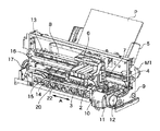
図7は、本発明に係るインクジェット記録装置の構成の概要を示す外観斜視図である。
<Description of inkjet recording apparatus>
FIG. 7 is an external perspective view showing an outline of the configuration of the ink jet recording apparatus according to the present invention.
図7に示すように、インクジェット記録装置(以下、単に記録装置ともいう)は、インクジェット方式に従ってインクを吐出して記録を行なう記録ヘッド3を搭載したキャリッジ2にキャリッジモータM1によって発生する駆動力を伝達機構4より伝え、キャリッジ2を矢印A方向に往復移動させるとともに、例えば、記録紙などの記録媒体Pを給紙機構5を介して給紙し、記録位置まで搬送し、その記録位置において記録ヘッド3から記録媒体Pにインクを吐出することで記録を行なう。
As shown in FIG. 7, an ink jet recording apparatus (hereinafter also simply referred to as a recording apparatus) applies a driving force generated by a carriage motor M1 to a
また、記録ヘッド3の状態を良好に維持するためにキャリッジ2を回復装置10の位置まで移動させ、間欠的に記録ヘッド3の吐出回復処理を行う。
Further, in order to maintain the state of the
記録装置のキャリッジ2には記録ヘッド3を搭載するのみならず、記録ヘッド3に供給するインクを貯留するインクカートリッジ6を装着する。インクカートリッジ6はキャリッジ2に対して着脱自在になっている。
In addition to mounting the
図7に示した記録装置はカラー記録が可能であり、そのためにキャリッジ2にはマゼンタ(M)、シアン(C)、イエロ(Y)、ブラック(K)のインクを夫々、収容した4つのインクカートリッジを搭載している。これら4つのインクカートリッジは夫々独立に着脱可能である。
The recording apparatus shown in FIG. 7 is capable of color recording. For this purpose, the
さて、キャリッジ2と記録ヘッド3とは、両部材の接合面が適正に接触されて所要の電気的接続を達成維持できるようになっている。記録ヘッド3は、記録信号に応じてエネルギーを印加することにより、複数の吐出口からインクを選択的に吐出して記録する。特に、この実施形態の記録ヘッド3は、熱エネルギーを利用してインクを吐出するインクジェット方式を採用し、熱エネルギーを発生するために電気熱変換体を備え、その電気熱変換体に印加される電気エネルギーが熱エネルギーへと変換され、その熱エネルギーをインクに与えることにより生じる膜沸騰による気泡の成長、収縮によって生じる圧力変化を利用して、吐出口よりインクを吐出させる。この電気熱変換体は各吐出口のそれぞれに対応して設けられ、記録信号に応じて対応する電気熱変換体にパルス電圧を印加することによって対応する吐出口からインクを吐出する。
Now, the
図7に示されているように、キャリッジ2はキャリッジモータM1の駆動力を伝達する伝達機構4の駆動ベルト7の一部に連結されており、ガイドシャフト13に沿って矢印A方向に摺動自在に案内支持されるようになっている。従って、キャリッジ2は、キャリッジモータM1の正転及び逆転によってガイドシャフト13に沿って往復移動する。また、キャリッジ2の移動方向(矢印A方向)に沿ってキャリッジ2の絶対位置を示すためのスケール8が備えられている。この実施形態では、スケール8は透明なPETフィルムに必要なピッチで黒色のバーを印刷したものを用いており、その一方はシャーシ9に固着され、他方は板バネ(不図示)で支持されている。
As shown in FIG. 7, the
また、記録装置には、記録ヘッド3の吐出口(不図示)が形成された吐出口面に対向してプラテン(不図示)が設けられており、キャリッジモータM1の駆動力によって記録ヘッド3を搭載したキャリッジ2が往復移動されると同時に、記録ヘッド3に記録信号を与えてインクを吐出することによって、プラテン上に搬送された記録媒体Pの全幅にわたって記録が行われる。
Further, the recording apparatus is provided with a platen (not shown) facing the discharge port surface where the discharge port (not shown) of the
さらに、図7において、14は記録媒体Pを搬送するために搬送モータM2によって駆動される搬送ローラ、15はバネ(不図示)により記録媒体Pを搬送ローラ14に当接するピンチローラ、16はピンチローラ15を回転自在に支持するピンチローラホルダ、17は搬送ローラ14の一端に固着された搬送ローラギアである。そして、搬送ローラギア17に中間ギア(不図示)を介して伝達された搬送モータM2の回転により、搬送ローラ14が駆動される。
Further, in FIG. 7, 14 is a transport roller driven by a transport motor M2 to transport the recording medium P, 15 is a pinch roller that abuts the recording medium P against the
またさらに、20は記録ヘッド3によって画像が形成された記録媒体Pを記録装置外ヘ排出するための排出ローラであり、搬送モータM2の回転が伝達されることで駆動されるようになっている。なお、排出ローラ20は記録媒体Pをバネ(不図示)により圧接する拍車ローラ(不図示)により当接する。22は拍車ローラを回転自在に支持する拍車ホルダである。
Further,
またさらに、記録装置には、図7に示されているように、記録ヘッド3を搭載するキャリッジ2の記録動作のための往復運動の範囲外(記録領域外)の所望位置(例えば、ホームポジションに対応する位置)に、記録ヘッド3の吐出不良を回復するための回復装置10が配設されている。
Further, as shown in FIG. 7, the recording apparatus includes a desired position (for example, a home position) outside the range of reciprocating motion (outside the recording area) for the recording operation of the
回復装置10は、記録ヘッド3の吐出口面をキャッピングするキャッピング機構11と記録ヘッド3の吐出口面をクリーニングするワイピング機構12を備えており、キャッピング機構11による吐出口面のキャッピングに連動して回復装置内の吸引手段(吸引ポンプ等)により吐出口からインクを強制的に排出させ、それによって、記録ヘッド3のインク流路内の粘度の増したインクや気泡等を除去するなどの吐出回復処理を行う。
The
また、非記録動作時等には、記録ヘッド3の吐出口面をキャッピング機構11によるキャッピングすることによって、記録ヘッド3を保護するとともにインクの蒸発や乾燥を防止することができる。一方、ワイピング機構12はキャッピング機構11の近傍に配され、記録ヘッド3の吐出口面に付着したインク滴を拭き取るようになっている。
Further, when the
これらキャッピング機構11及びワイピング機構12により、記録ヘッド3のインク吐出状態を正常に保つことが可能となっている。
The
<画像処理の流れ>
次に、本実施形態のインクジェット記録システム(インクジェット記録装置とホスト機器を含むシステム)における画像処理の流れについて図2を用いて説明する。なお、上述のように、ここで説明する画像処理の一部、詳しくは、ホスト機器で実行される画像処理は、ホスト機器で画像データの記録が指示されたときに、プリンタドライバが起動され、設定に従って主制御部108によって実行される。
<Image processing flow>
Next, the flow of image processing in the ink jet recording system of this embodiment (a system including an ink jet recording apparatus and a host device) will be described with reference to FIG. As described above, a part of the image processing described here, specifically, the image processing executed by the host device is such that when the host device is instructed to record image data, the printer driver is activated, It is executed by the
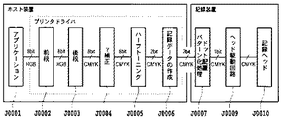
図2は、本実施形態のインクジェット記録システムにおける画像データ変換処理の流れを示したブロック図である。本実施形態で適用するインクジェット記録装置は、シアン、マゼンタ、イエロー、ブラックの4色のインクを用いて記録を行うものであり、そのためにこれら4色のインクを吐出する記録ヘッドが用意されている。図2に示すように、ここに示す各処理は、記録装置とホスト機器としてのパーソナルコンピュータ(PC)によって構成されるものとする。 FIG. 2 is a block diagram showing a flow of image data conversion processing in the ink jet recording system of this embodiment. The ink jet recording apparatus applied in the present embodiment performs recording using inks of four colors of cyan, magenta, yellow, and black. For this purpose, a recording head that discharges these four colors of ink is prepared. . As shown in FIG. 2, each processing shown here is assumed to be configured by a recording device and a personal computer (PC) as a host device.
ホスト装置のオペレーティングシステムで動作するプログラムとしてアプリケーションやプリンタドライバがあり、アプリケーションJ0001は記録装置で記録される画像に対応した画像データを作成する処理を実行する。実際の記録時にはアプリケーションで作成された画像データがプリンタドライバに渡される。 There are an application and a printer driver as programs that operate in the operating system of the host device, and the application J0001 executes processing for creating image data corresponding to an image recorded by the recording device. At the time of actual recording, image data created by the application is passed to the printer driver.
本実施形態におけるプリンタドライバはその処理として、前段処理J0002、後段処理J0003、γ補正J0004、多値量子化であるハーフトーニングJ0005、および記録データ作成J0006を有するものとする。ここで、各処理を簡単に説明すると、前段処理J0002は色域(Gamut)のマッピングを行う。例えば、sRGB規格の画像データであれば、sRGB規格の画像データR、G、Bによって再現される色域を、記録装置によって再現される色域内に写像するためのデータ変換を行う。具体的にはR、G、Bのそれぞれが8bitで表現されたデータを3次元ルックアップテーブル(3DLUT)を用いることにより、記録装置で表現可能な色域に依存したR、G、Bの8bitデータに変換する。 Assume that the printer driver in the present embodiment includes pre-processing J0002, post-processing J0003, γ correction J0004, halftoning J0005 that is multi-level quantization, and print data creation J0006 as processing. Here, each process will be briefly described. The pre-stage process J0002 performs color gamut mapping. For example, in the case of sRGB standard image data, data conversion is performed to map the color gamut reproduced by the sRGB standard image data R, G, B into the color gamut reproduced by the recording apparatus. Specifically, by using a 3D lookup table (3DLUT) for data in which R, G, and B are each expressed in 8 bits, 8 bits of R, G, and B depending on the color gamut that can be expressed by the recording apparatus Convert to data.
後段処理J0003は、前段処理J0002で得られた8bitデータR、G、Bを、このRGBデータが表す色を再現するインクの組み合わせに対応した色分解データ(ここでは、8bitデータC、M、Y、K)に変換する処理を行う。ここでは、RGBデータとインクに対応したCMYKデータとが1対1に対応付けられた変換テーブル(例えば、3次元ルックアップテーブル)を用いるにより、RGBデータをCMYKデータに変換する。詳しくは、3次元ルックアップテーブルにおいては、それぞれが8bit(0〜255)で表現されるR、G、Bの値と、それぞれが8bit(0〜255)で表現されるCMYKの値とが予め対応付けられており、
(R,G,B)=(0〜255,0〜255,0〜255)から
(C,M,Y,K)=(0〜255,0〜255,0〜255,0〜255)
への変換が行われる。
The post-stage process J0003 is a color separation data (here, 8-bit data C, M, Y) corresponding to a combination of inks that reproduce the colors represented by the RGB data, using the 8-bit data R, G, B obtained in the pre-stage process J0002. , K). Here, the RGB data is converted into CMYK data by using a conversion table (for example, a three-dimensional lookup table) in which the RGB data and the CMYK data corresponding to ink are associated one-to-one. Specifically, in the three-dimensional lookup table, R, G, and B values each represented by 8 bits (0 to 255) and CMYK values each represented by 8 bits (0 to 255) are stored in advance. Associated with,
From (R, G, B) = (0-255,0-255,0-255) (C, M, Y, K) = (0-255,0-255,0-255,0-255)
Conversion to
例えば、
(R,G,B)=(0,0,0)であれば、
(C,M,Y,K)=(0,0,0,255)に変換され、また、
(R,G,B)=(255,255,255)であれば、
(C,M,Y,K)=(0,0,0,255)に変換され、また、
(R,G,B)=(0,128,0)であれば、
(C,M,Y,K)=(0,128,128,0)に変換される。
なお、本実施形態では、このような変換テーブルが少なくとも2種類設けられており、後述する条件に応じて変換テーブルを切り換えている。
For example,
If (R, G, B) = (0, 0, 0),
(C, M, Y, K) = (0, 0, 0, 255), and
If (R, G, B) = (255, 255, 255),
(C, M, Y, K) = (0, 0, 0, 255), and
If (R, G, B) = (0, 128, 0),
(C, M, Y, K) = (0, 128, 128, 0).
In the present embodiment, at least two types of such conversion tables are provided, and the conversion tables are switched according to conditions described later.
γ補正J0004は、後段処理J0003により得られた色分解データの各インク色データごとにその階調値変換を行う。具体的には、記録装置の各色インクの階調特性に応じた1次元LUTを用いることにより、上記色分解データが記録装置の階調特性に線形的に対応づけられるような変換を行う。 The γ correction J0004 performs gradation value conversion for each ink color data of the color separation data obtained by the post-processing J0003. Specifically, by using a one-dimensional LUT corresponding to the gradation characteristics of each color ink of the recording apparatus, conversion is performed so that the color separation data is linearly associated with the gradation characteristics of the recording apparatus.
ハーフトーニングJ0005は、8ビットの色分解データY、M、C、Kそれぞれについて2ビットのデータに変換する量子化を行う。本実施形態では、多値の誤差拡散法を用いて256階調の8ビットデータを、3階調の2ビットデータに変換する。この2ビットデータは、記録装置で行われるドット配置パターン化処理における配置パターンを示すためのインデックスとなるデータである。 Halftoning J0005 performs quantization by converting 8-bit color separation data Y, M, C, and K into 2-bit data. In this embodiment, multi-level error diffusion is used to convert 256-gradation 8-bit data into 3-gradation 2-bit data. This 2-bit data is data serving as an index for indicating an arrangement pattern in the dot arrangement patterning process performed in the printing apparatus.
プリンタドライバで行う処理の最後には、記録データ作成処理J0006によって、上記2ビットのインデックスデータを内容とする記録イメージデータに記録制御情報を加えた記録データを作成する。ホスト機器は、この記録データを記録装置へ送信する。 At the end of the process performed by the printer driver, print data is created by adding print control information to the print image data containing the above-mentioned 2-bit index data by print data creation process J0006. The host device transmits this recording data to the recording device.
記録装置は、ホスト機器から送信された記録データに対し、ドット配置パターン化処理J0007を行う。 The recording apparatus performs a dot arrangement patterning process J0007 on the recording data transmitted from the host device.
ここで、ドット配置パターン化処理J0007について説明する。上述したハーフトーン処理では、256値の多値濃度情報(8ビットデータ)を3値の階調値情報(2ビットデータ)までにレベル数を下げている。しかし、実際に本実施形態のインクジェット記録装置が記録できる情報は、インクを記録するか否かの2値情報である。ドット配置パターン化処理では、0〜2の3値レベルをドットの有無を決定する2値レベルまで低減する役割を果たす。具体的には、このドット配置パターン化処理J0007では、ハーフトーン処理部からの出力値であるレベル0〜2の2ビットデータで表現される画素ごとに、その画素の階調値(レベル0〜2)に対応したドット配置パターンを割当て、これにより1画素内の複数のエリア各々にドットのオン・オフを定義し、1画素内の各エリアに「1」または「0」の1ビットの吐出データを配置する。 Here, the dot arrangement patterning process J0007 will be described. In the halftone process described above, the number of levels is reduced from 256-value multi-value density information (8-bit data) to ternary tone value information (2-bit data). However, information that can be actually recorded by the ink jet recording apparatus of the present embodiment is binary information indicating whether or not to record ink. In the dot arrangement patterning process, it plays a role of reducing the ternary level from 0 to 2 to the binary level that determines the presence or absence of dots. Specifically, in this dot arrangement patterning process J0007, for each pixel represented by 2-bit data of level 0 to 2 that is an output value from the halftone processing unit, the gradation value (level 0 to 0) of that pixel is represented. A dot arrangement pattern corresponding to 2) is assigned, whereby dot on / off is defined in each of a plurality of areas in one pixel, and ejection of 1 bit of “1” or “0” in each area in one pixel Arrange the data.
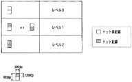
図8は、本実施形態のドット配置パターン化処理で変換する、入力レベル0〜2に対する出力パターンを示している。図の右に示した各レベル値は、ハーフトーン処理部からの出力値であるレベル0〜レベル2に相当している。左側に配列した縦2エリア×横1エリアで構成される領域は、ハーフトーン処理で出力された1画素(ピクセル)の領域に対応するもので、縦横ともに600ppi(ピクセル/インチ;参考値)の画素密度に対応する大きさとなっている。また、1画素内の各エリアは、ドットのオン・オフが定義される最小単位に相当するもので、縦が1200dpi(ドット/インチ;参考値)、横が600dpiの記録密度に対応する。本実施形態の記録装置では、上記記録密度に対応した、縦が約20μm、横が約40μmで表現される1つのエリアに対し、所定量のインク滴が1つ記録されて所望の濃度が得られる様に設計されている。図において、塗りつぶしたエリアがドットの記録を行うエリアを示しており、レベル数が上がるに従って、記録するドット数が1つずつ増加している。
FIG. 8 shows output patterns for input levels 0 to 2 that are converted by the dot arrangement patterning process of the present embodiment. Each level value shown on the right side of the drawing corresponds to level 0 to
入力レベル1の場合、パターンは2種類用意されている。すなわち、縦に2つ並ぶエリアのうち、上のエリアを記録するパターンと、下のエリアを記録するパターンである。このように、同値の濃度を表現できるパターンが複数存在する場合、固定されたパターンのみで濃度表現を行ってしまうと、画像上にテクスチャーや擬似輪郭が発生する場合がある。よって、本実施形態では、同値の濃度を表現する場合にも複数のパターンを混在して配列させる構成が採用されている。 In the case of the input level 1, two types of patterns are prepared. That is, a pattern for recording the upper area and a pattern for recording the lower area among the two areas arranged vertically. As described above, when there are a plurality of patterns capable of expressing the same density, if the density expression is performed only with the fixed pattern, a texture or a pseudo contour may be generated on the image. Therefore, in the present embodiment, a configuration is adopted in which a plurality of patterns are mixedly arranged even when expressing the same density.
再度図2を参照するに、ドット配置パターン化処理が施された各色の2値データは、次に駆動回路J0009に入力すれる。駆動回路J0009に入力された各色の1bitデータは、記録ヘッドJ0010の駆動パルスに変換され、各色の記録ヘッドJ0010より所定のタイミングでインクが吐出される。 Referring to FIG. 2 again, the binary data of each color that has been subjected to the dot arrangement patterning process is then input to the drive circuit J0009. The 1-bit data of each color input to the driving circuit J0009 is converted into a driving pulse for the recording head J0010, and ink is ejected from the recording head J0010 for each color at a predetermined timing.
<記録ヘッドの構成と記録走査による色味の差>
図3は、本実施形態のインクジェット記録装置で使用される記録ヘッド3の各色ノズル列の配置を模式的に示す図である。この図では、記録ヘッド3を上方から見た場合のノズル列の配置を示している。
<Color difference due to print head configuration and print scan>
FIG. 3 is a diagram schematically showing the arrangement of each color nozzle row of the
図中、301〜304はそれぞれ、インクを吐出するノズル列を示しており、301がブラックインク、302がシアンインク、303がマゼンタインク、304がイエローインクを吐出するノズル列をそれぞれ示している。図示した構成では、各ノズル列を構成するノズルの数は等しく、例えば256個のノズルを含んでいる。
In the figure,
なお、記録ヘッドのノズル列の配置は、図3に示した例に限定されず、並び順や各列に含まれるノズル数が異なるものなど様々な形態のものが使用可能である。また、図3の例では、各色のノズル列が1つのチップに一体形成された形態のヘッドであるが、各色ノズル列は別チップに別体形成された形態のヘッドであってもよい。また、4色(CMYK)のうちある1色(例えば、K)のノズル列と残り3色(例えば、CMY)のノズル列とが別チップに形成された形態であってもよい。 The arrangement of the nozzle rows of the recording head is not limited to the example shown in FIG. 3, and various forms such as those in which the arrangement order and the number of nozzles included in each row are different can be used. In the example of FIG. 3, the nozzle row of each color is a head that is integrally formed on one chip, but each color nozzle row may be a head that is formed separately on another chip. Further, one nozzle (for example, K) of four colors (CMYK) and the remaining three (for example, CMY) nozzle arrays may be formed in different chips.
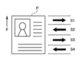
図4は、1枚の記録媒体に記録を行なう際の記録ヘッドによる走査の例を示す図である。図示した例では、記録媒体Pは矢印F方向に搬送され、先端側からS1、S2、S3、S4でそれぞれ示す4回の走査(パス)で記録される。ここで、S1及びS3で示す走査は記録ヘッドが左から右へ移動する往方向走査であり、S2及びS4で示す走査では左から右へと記録ヘッドが移動する復方向走査である。 FIG. 4 is a diagram illustrating an example of scanning by the recording head when recording is performed on one recording medium. In the illustrated example, the recording medium P is conveyed in the direction of arrow F and recorded by four scans (passes) indicated by S1, S2, S3, and S4 from the leading end side. Here, scanning indicated by S1 and S3 is forward scanning in which the recording head moves from left to right, and scanning indicated by S2 and S4 is backward scanning in which the recording head moves from left to right.
図3に示したようなノズル列を有する記録ヘッドを用いて、このような記録走査を行なうと、S1及びS3の走査では、イエロー、マゼンダ、シアン、ブラックの順にインク滴が吐出され、S2及びS4の走査では、ブラック、シアン、マゼンダ、イエローの順にインク滴が吐出されるので、走査方向によって記録媒体に吐出される(打ち込まれる)インクの順序が異なる。その為、複数色のインクで表現される画素については、各インクを同じ量だけ吐出したとしても、色味が異なってしまう。この色味の差(色差)が大きくなると色ムラと知覚される。 When such a recording scan is performed using a recording head having a nozzle row as shown in FIG. 3, ink droplets are ejected in the order of yellow, magenta, cyan, and black in the scans of S1 and S3. In the scan of S4, since ink droplets are ejected in the order of black, cyan, magenta, and yellow, the order of ink ejected (printed) onto the recording medium differs depending on the scanning direction. For this reason, even if the same amount of ink is ejected from pixels expressed by a plurality of colors of ink, the colors are different. When this color difference (color difference) increases, it is perceived as color unevenness.
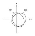
図5は、往方向走査と復方向走査での色再現範囲を示すグラフである。この図では、CIE−L*a*b*空間上に示した色再現範囲をab平面上に投影して示したものである。例えば501が往方向走査での記録により可能な色再現範囲であり、502が復方向走査での記録により可能な色再現範囲である。図5から明らかなように、走査方向によって色再現範囲が異なる。この色再現範囲の相違は、往復でインクの重なり順が異なることに起因する。
FIG. 5 is a graph showing a color reproduction range in forward scanning and backward scanning. In this figure, the color reproduction range shown on the CIE-L * a * b * space is projected onto the ab plane. For example,
さて、上述したように往走査で記録される色と復走査で記録される色の色差(ΔE)が大きくなる場合、この色差が色ムラと知覚される。従って、このような場合には、この色差を低減させる画像処理を行う必要がある。そこで、本実施形態においては、色差が大きくなって色ムラとして知覚される可能性が高い場合には、使用する変換テーブル(具体的には、後段処理で用いる3次元ルックアップテーブル)を変更するようにしている。
なお、CIE−L*a*b*空間で、2つの測色値(L1*,a1*,b1*)と(L2*,a2*,b2*)との間の色差ΔEは、
ΔE={(ΔL*)2+(Δa*)2+(Δb*)2}1/2
で定められる。但し、
ΔL*=L1*−L2*
Δa*=a1*−a2*
Δb*=b1*−b2*
である。
As described above, when the color difference (ΔE) between the color recorded in the forward scanning and the color recorded in the backward scanning becomes large, this color difference is perceived as color unevenness. Therefore, in such a case, it is necessary to perform image processing for reducing the color difference. Therefore, in the present embodiment, when there is a high possibility that the color difference becomes large and is perceived as color unevenness, the conversion table to be used (specifically, the three-dimensional lookup table used in subsequent processing) is changed. I am doing so.
In the CIE-L * a * b * space, the color difference ΔE between the two colorimetric values (L1 * , a1 * , b1 * ) and (L2 * , a2 * , b2 * ) is
ΔE = {(ΔL * ) 2 + (Δa * ) 2 + (Δb * ) 2 } 1/2
Determined by However,
ΔL * = L1 * −L2 *
Δa * = a1 * −a2 *
Δb * = b1 * −b2 *
It is.
本実施形態では、2種類の変換テーブル(第1の変換テーブル、第2の変換テーブル)を設けており、色ムラが発生しずらい画像データの場合には第1の変換テーブルを使用する一方で、色ムラが発生しやすい画像データの場合には走査方向に応じて使用する変換テーブルを切り換えるようにしている。具体的には、往走査で使用するデータを作成する画像処理時には第1の変換テーブルを使用し、復走査で使用するデータを作成する画像処理時には第2の変換テーブルを使用するようにしている。 In this embodiment, two types of conversion tables (a first conversion table and a second conversion table) are provided, and in the case of image data in which color unevenness is difficult to occur, the first conversion table is used. Thus, in the case of image data in which color unevenness is likely to occur, the conversion table to be used is switched according to the scanning direction. Specifically, the first conversion table is used during image processing for creating data used in forward scanning, and the second conversion table is used during image processing for creating data used for backward scanning. .
ここで、第1の変換テーブルは、画像データに関係なく、少なくとも往走査データを作成する際に使用される基本テーブルである。色ムラが発生しずらい画像データの場合には往復両走査データを作成するために使用され、また、色ムラが発生しやすい画像データの場合には往走査データのみを作成するために使用される。一方、第2の変換テーブルは色ムラが発生しやすい画像データの場合のときだけに使用される色差低減テーブルである。色ムラが発生しやすい画像データの場合において復走査データを作成するために使用される。 Here, the first conversion table is a basic table used when creating at least forward scan data regardless of image data. It is used to create reciprocal scan data for image data that is less likely to cause color unevenness, and it is used to create only forward scan data for image data that is more likely to cause color unevenness. The On the other hand, the second conversion table is a color difference reduction table used only in the case of image data in which color unevenness is likely to occur. In the case of image data in which color unevenness is likely to occur, it is used to create reverse scan data.
第2の変換テーブルは、往走査で記録される場合の色に近づくようにデータ変換がなされる構成となっている。つまり、第2のテーブルは第1のテーブル使用して往方向で記録を行った際に現れる色をターゲットとして作成されており、同じRGB値が入力された場合、復方向において第2のテーブルを用いて記録された色は、往方向において第1のテーブルを用いて記録された色になるべく近づく様に調整される。この結果、往復両走査のデータを第1の変換テーブルを用いて作成した場合よりも、往走査で第1の変換テーブルを用い且つ復走査で第2の変換テーブルを用いてデータを作成した場合の方が、往走査で記録された場合と復走査で記録された場合の色差が低減されることになる。 The second conversion table has a configuration in which data conversion is performed so as to approximate the color in the case of printing by forward scanning. In other words, the second table is created using the first table as a target for the color that appears when recording in the forward direction.If the same RGB value is input, the second table is used in the backward direction. The color recorded using is adjusted so as to be as close as possible to the color recorded using the first table in the forward direction. As a result, when the data is generated using the first conversion table in the forward scan and using the second conversion table in the backward scan, compared to the case where the data of both reciprocal scans are generated using the first conversion table. In this case, the color difference between when printing is performed by forward scanning and when recording is performed by backward scanning is reduced.
<変換テーブルの切り換え処理>
以下、図6に示すプリンタドライバによる記録データ生成処理のフローチャートを参照して、本実施形態における変換テーブルの切り換え処理について説明する。
<Conversion table switching process>
Hereinafter, the conversion table switching process in this embodiment will be described with reference to the flowchart of the print data generation process by the printer driver shown in FIG.
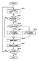
まず、ステップS601で1回の走査(パス)で記録する画像データが入力される。つまり、1バンドに対応した画像データが入力されるのである。なお、上述したように画像データは8bitのRGBデータとなっている。次にステップS602にて、上記1バンドに対応した画像データが色ムラの発生しやすい画像データであるか否かを判定する。本実施形態では、色ムラの発生しやすい画像データであるか否かを判定するために、その画像データの中に特定の色の画素が所定数以上含まれているか否かのチェックを行なう。ここで、所定数は1以上の整数であればよいが、その最適値は、普通紙かコート紙か等のメディアの種類、はやい、標準、きれい等の記録モード、および染料か顔料か等のインク種別を考慮して決定される。 First, image data to be recorded in one scan (pass) is input in step S601. That is, image data corresponding to one band is input. As described above, the image data is 8-bit RGB data. Next, in step S602, it is determined whether the image data corresponding to the one band is image data in which color unevenness is likely to occur. In this embodiment, in order to determine whether or not the image data is likely to have color unevenness, it is checked whether or not a predetermined number or more of pixels of a specific color are included in the image data. Here, the predetermined number may be an integer greater than or equal to 1, but the optimum value is the type of media such as plain paper or coated paper, fast, standard, recording mode such as clean, and whether it is dye or pigment. It is determined in consideration of the ink type.
ここで、特定の色とは、往方向走査で記録される色と復方向走査で記録される色との差が所定の色差(例えば、ΔE=2)以上の色である。例えば、往復両方向で記録される色差ΔEが2以上となる色を予めデータベースに登録しておき、入力された画像データ内に含まれる各画素をデータベースと照合することによりステップS602のチェックを行なう。なお、このステップS602の段階では、上記1バンドに対応した画像データを構成する各画素に対応するデータはRGB値で表現されている。従って、色差ΔEが2以上となる色に対応したRGB値を予め登録しておき、画素のRGB値が上記登録してあるRGB値と一致するか否かを検索することにより、色差ΔEが2以上となる色か否かが決定されることになる。 Here, the specific color is a color in which the difference between the color recorded in the forward scanning and the color recorded in the backward scanning is a predetermined color difference (for example, ΔE = 2) or more. For example, a color having a color difference ΔE recorded in both directions of two or more is registered in advance in the database, and each pixel included in the input image data is checked against the database to check in step S602. Note that in the stage of step S602, data corresponding to each pixel constituting the image data corresponding to the one band is expressed by RGB values. Therefore, by registering in advance an RGB value corresponding to a color having a color difference ΔE of 2 or more and searching whether the RGB value of the pixel matches the registered RGB value, the color difference ΔE is 2 Whether the color is the above or not is determined.
ステップS602で特定の色の画素が所定数以上含まれていなければ、つまり、色ムラが発生しにくいバンドの場合には、走査方向に関わらず、第1の変換テーブルを読み出し、ステップS606へ進む。一方、ステップS602で特定の色の画素が所定数以上含まれていれば、つまり、色ムラが発生しやすいバンドの場合には、ステップS603に進み、走査方向が往方向であるか否かのチェックを行ない、往方向記録であればステップS604に進んで第1の変換テーブルを読み出す。一方、走査方向が復方向であればステップS605に進んで第2の変換テーブルを読み出す。 If a predetermined number or more of pixels of a specific color are not included in step S602, that is, if the band is less likely to cause color unevenness, the first conversion table is read regardless of the scanning direction, and the process proceeds to step S606. . On the other hand, if a predetermined number or more of pixels of a specific color are included in step S602, that is, if the band is likely to cause color unevenness, the process proceeds to step S603 to check whether the scanning direction is the forward direction. A check is made, and if it is forward direction recording, the process advances to step S604 to read the first conversion table. On the other hand, if the scanning direction is the backward direction, the process proceeds to step S605 to read the second conversion table.
なお、本実施形態で走査方向によって切り換える変換テーブルは、図2の後段処理J0003で使用する、RGBで表現されるデータからCMYKで表現されるデータへの色変換処理を行うための変換テーブルである。 Note that the conversion table to be switched according to the scanning direction in this embodiment is a conversion table for performing color conversion processing from data expressed in RGB to data expressed in CMYK, which is used in the subsequent processing J0003 in FIG. .
その後、ステップS606にて、上記変換テーブルを用いて行う後段処理J0003を含む画像処理(詳しくは、図2で説明した後段処理0003、γ補正処理J0004、ハーフトーン処理J0005等)を経て記録データを生成し、ステップS607にて生成された記録データを記録装置に送信する。 Thereafter, in step S606, the recording data is subjected to image processing including post-processing J0003 performed using the conversion table (specifically, post-processing 0003, γ correction processing J0004, halftone processing J0005, etc. described in FIG. 2). The recording data generated in step S607 is transmitted to the recording apparatus.
ここで、ステップS606にて行われる後段処理J0003について述べる。ステップS606の前にステップS604を経ている場合には第1の変換テーブルを用いたデータ処理がなされ、ステップS606の前にステップS605を経ている場合には第2の変換テーブルを用いたデータ処理がなされる。これにより、色ムラが発生しやすい場合であっても、往復走査での色ムラを低減することができる。一方、ステップS604やステップS605を経ずしてステップS602から直接ステップS606に至る場合、つまり、ステップS602において色ムラが発生しずらい画像データと判定された場合、走査方向に関わらず、第1の変換テーブルを用いたデータ処理がなされる。 Here, the post-processing J0003 performed in step S606 will be described. When step S604 is performed before step S606, data processing using the first conversion table is performed, and when step S605 is performed before step S606, data processing using the second conversion table is performed. Made. Thereby, even when color unevenness is likely to occur, color unevenness in reciprocating scanning can be reduced. On the other hand, when the process directly goes from step S602 to step S606 without passing through step S604 or step S605, that is, when it is determined in step S602 that the color unevenness is unlikely to occur, the first data is displayed regardless of the scanning direction. Data processing using the conversion table is performed.
そして、ステップS608にて全てのパスの記録データの処理が終了したか否かをチェックし、終了していなければステップS601に戻り、以降の処理を繰り返す。ステップS608で全てのパスの記録データの処理が終了したと判定された場合には処理を終了する。 In step S608, it is checked whether or not the processing of the recording data for all passes has been completed. If not, the process returns to step S601 to repeat the subsequent processing. If it is determined in step S608 that the recording data processing for all passes has been completed, the processing ends.
以上説明したように、本実施形態によれば、所定以上の色差が生じる画素が所定数以上含まれるような色ムラが発生しやすい場合に、記録データの生成に使用する変換テーブルを走査方向に応じて切り換える。 As described above, according to the present embodiment, when color unevenness is likely to occur in which a predetermined number or more of pixels having a color difference greater than or equal to a predetermined number are included, the conversion table used for generating print data is set in the scanning direction. Switch accordingly.
このため、往復走査での色味差を低減することができる。 For this reason, the color difference in reciprocating scanning can be reduced.
<他の実施形態>
上記の実施形態では、第1および第2の変換テーブルを設け、色ムラが目立ちやすい場合には走査方向に応じて2種類の変換テーブルを切り換える一方で、色ムラが目立ちにくい場合には走査方向に関わらず第1の変換テーブルを用いる構成であったが、変換テーブルの数は2種類に限られるものではない。例えば、3種類の変換テーブル(変換テーブルA〜C)を設けておき、色ムラが目立ちにくい場合には走査方向に関わらず基本テーブル(変換テーブルA)を使用し、色ムラが目立ちやすい場合には走査方向に応じて2種類の色差低減変換テーブル(変換テーブルB、C)を切り換える構成であってもよい。いずれにせよ、色ムラが目立ちやすい場合に、走査方向に応じた2種類の変換テーブルの切り換えが行われればよい。
<Other embodiments>
In the above-described embodiment, the first and second conversion tables are provided, and when the color unevenness is easily noticeable, the two types of conversion tables are switched according to the scanning direction. Regardless of the configuration, the first conversion table is used, but the number of conversion tables is not limited to two. For example, when three types of conversion tables (conversion tables A to C) are provided and the color unevenness is not noticeable, the basic table (conversion table A) is used regardless of the scanning direction, and the color unevenness is easily noticeable. May be configured to switch between two types of color difference reduction conversion tables (conversion tables B and C) according to the scanning direction. In any case, when color unevenness is conspicuous, it is only necessary to switch between two types of conversion tables in accordance with the scanning direction.
また、上記の実施形態では、色差が所定以上となる特定の色の画素が所定数以上含まれているか否かに応じて、変換テーブルを切り換えるか否かを決定しているが、変換テーブルを切り換えるか否かの判定基準はこの例に限られるものではない。上述したようにこの判定基準は、色ムラを生じやすい画像データか否かを判定できればよく、例えば、画像データに黒以外の画素(カラーデータ)が所定数含まれているか否かを判断基準としてもよい。黒データのみの場合は往復の色ムラは発生し得ず、カラーデータを含む場合にのみ往復の色ムラは発生する。そこで、1バンドに対応した画像データ中に黒以外のデータの画素が含まれるか否かを判断基準とすることも有効である。これは、例えば、写真と文字とが混在する文書などでは有効である。 In the above embodiment, whether or not to switch the conversion table is determined depending on whether or not a predetermined number of pixels of a specific color with a color difference equal to or greater than a predetermined value are included. The criterion for determining whether or not to switch is not limited to this example. As described above, this determination criterion only needs to be able to determine whether the image data is likely to cause color unevenness. For example, whether the image data includes a predetermined number of pixels (color data) other than black is used as the determination criterion. Also good. In the case of only black data, reciprocal color unevenness cannot occur, and reciprocal color unevenness occurs only when color data is included. Therefore, it is also effective to use whether or not pixels of data other than black are included in image data corresponding to one band. This is effective, for example, in a document in which photographs and characters are mixed.
また、一般にインクジェット方式の記録装置で走査方向による色の違いが顕著となるのは、インクの使用量が多い場合であるので、変換テーブルを切り換えるか否かの判定基準を、インクの使用量が所定以上の画素が所定数以上含まれているか否かとしてもよい。ここで、所定数は1以上の整数である。 Also, in general, the difference in color depending on the scanning direction becomes significant in an ink jet recording apparatus when the amount of ink used is large. Therefore, the criterion for determining whether to switch the conversion table is the ink usage amount. It may be determined whether or not a predetermined number or more of pixels are included. Here, the predetermined number is an integer of 1 or more.
更に、上記実施形態では、走査方向に応じて切り換える変換テーブルとして、RGBで表現されるデータから使用インクに対応したCMYKで表現されるデータへの色変換処理を行う変換テーブルを例に挙げているが、走査方向に応じて切り換える変換テーブルは、この種類の変換テーブルに限定されるものではない。図2に示したような画像処理で使用される変換テーブルの少なくとも1つであればよく、例えば、前段処理J0002で使用される変換テーブルを切り換えるようにしてもよい。 Furthermore, in the above-described embodiment, as a conversion table that is switched according to the scanning direction, a conversion table that performs color conversion processing from data expressed in RGB to data expressed in CMYK corresponding to the used ink is taken as an example. However, the conversion table switched according to the scanning direction is not limited to this type of conversion table. Any conversion table used in the image processing as shown in FIG. 2 may be used. For example, the conversion table used in the pre-stage processing J0002 may be switched.
また、上記の実施形態では、往復の色ムラを低減させるために、記録画素の色(色相、明度、彩度の少なくとも1つ)を変えることのできる変換テーブルを用いる例について説明したが、往復の色ムラを低減させる処理としては変換テーブルの変更に限られるものではない。要は、往復の色ムラを低減させるためには、記録画素の色(色相、明度、彩度の少なくとも1つ)を変えることができればよいわけである。そして、記録画素の色(色相、明度、彩度の少なくとも1つ)を変えためには、ハーフトーン処理の手法を変えたり、ドット配置パターンのドット配置の仕方を変えたりしてもよい。従って、走査方向に応じて、ハーフトーン処理の仕方やドット配置パターンのドット配置の仕方を変えることも有効である。勿論、このような変更を行うのは、色ムラが生じやすい画像データの場合に限られる。 In the above-described embodiment, an example is described in which a conversion table that can change the color (at least one of hue, brightness, and saturation) of a recording pixel is used to reduce reciprocal color unevenness. The process of reducing the color unevenness is not limited to changing the conversion table. In short, in order to reduce reciprocal color unevenness, it is only necessary to change the color of the recording pixel (at least one of hue, brightness, and saturation). In order to change the color (at least one of hue, brightness, and saturation) of the recording pixel, the halftone processing method may be changed or the dot arrangement method of the dot arrangement pattern may be changed. Therefore, it is also effective to change the halftone processing method and the dot arrangement method of the dot arrangement pattern according to the scanning direction. Of course, such a change is performed only in the case of image data in which color unevenness is likely to occur.
また、上記の実施形態では、CMYKの4種類のインクを用いる形態について説明したが、用いるインクの種類がこれに限定されないことはいうまでもない。例えば、CMYKの4種類にLC(ライトシアン)、LM(ライトマゼンタ)のインクを加えた6種類のインクを使用する形態であってもよい。この場合、後段処理で使用される変換テーブルは、RGBで表現されるデータを、上記6種類のインクに対応した色分解データに変換する。 Further, in the above-described embodiment, the mode of using four types of CMYK inks has been described, but it goes without saying that the type of ink to be used is not limited to this. For example, six types of inks may be used in which four types of CMYK plus LC (light cyan) and LM (light magenta) inks are used. In this case, the conversion table used in the subsequent process converts data expressed in RGB into color separation data corresponding to the above six types of ink.
加えて、上記の実施形態では、図2で説明した通り、ホスト機器内(プリンタドライバ)で後段処理J0003、γ補正処理J0004、ハーフトーン処理J0005、記録データ作成処理J0006を行い、インクジェット記録装置側でドットパターン配置処理J0007を行う形態であったが、これら処理J0003〜J0007はホスト機器とインクジェット記録装置のいずれで行っても良い。例えば、ホスト機器で前段処理J0002まで行い、後段処理J0003以降の画像処理を記録装置側で行う場合には、後段処理で用いる変換テーブルを走査方向に応じて切り換える処理を記録装置側で実行するようになる。 In addition, in the above embodiment, as described with reference to FIG. 2, the post-processing J0003, the gamma correction processing J0004, the halftone processing J0005, and the recording data creation processing J0006 are performed in the host device (printer driver). In this embodiment, the dot pattern arrangement processing J0007 is performed. However, these processing J0003 to J0007 may be performed by either the host device or the ink jet recording apparatus. For example, when the host device performs up to the pre-stage process J0002 and the image processing after the post-stage process J0003 is performed on the recording apparatus side, the recording apparatus side executes a process of switching the conversion table used in the post-stage process according to the scanning direction. become.
このように、本発明は、上記のように複数の機器から構成される記録システムに適用しても良いし、また、例えば、記憶媒体を挿入可能なスロットや、デジタルカメラ等の画像入力器を接続可能なインタフェースを有し、ホスト機器を接続せずに記憶媒体や画像入力機器に格納された画像データを直接記録することが可能な、いわゆるダイレクトプリンタのようなインクジェット記録装置に適用しても良い。ホスト機器を接続しないダイレクトプリンタの場合、前段処理J0002〜ドットパターン配置処理J0007を含む画像処理は全てインクジェット記録装置で行われる。 As described above, the present invention may be applied to a recording system including a plurality of devices as described above. For example, a slot into which a storage medium can be inserted and an image input device such as a digital camera are provided. Even when applied to an inkjet recording apparatus such as a so-called direct printer, which has a connectable interface and can directly record image data stored in a storage medium or an image input device without connecting a host device. good. In the case of a direct printer not connected to a host device, all image processing including pre-processing J0002 to dot pattern arrangement processing J0007 is performed by the ink jet recording apparatus.
なお、本発明は、前述した実施形態の機能を実現するソフトウェアのプログラム(本実施形態では図6に示すフローチャートに対応したプリンタドライバ)を、システム或いは装置に直接或いは遠隔から供給し、そのシステム或いは装置のコンピュータが該供給されたプログラムコードを読み出して実行することによっても達成される場合を含む。その場合、プログラムの機能を有していれば、形態は、プログラムである必要はない。 In the present invention, a software program (in this embodiment, a printer driver corresponding to the flowchart shown in FIG. 6) for realizing the functions of the above-described embodiment is directly or remotely supplied to a system or apparatus, and the system or This includes the case where the computer of the apparatus is also achieved by reading and executing the supplied program code. In that case, as long as it has the function of a program, the form does not need to be a program.
従って、本発明の機能処理をコンピュータで実現するために、該コンピュータにインストールされるプログラムコード自体も本発明を実現するものである。つまり、本発明のクレームでは、本発明の機能処理を実現するためのコンピュータプログラム自体も含まれる。 Accordingly, since the functions of the present invention are implemented by computer, the program code installed in the computer also implements the present invention. That is, the claims of the present invention include the computer program itself for realizing the functional processing of the present invention.
その場合、プログラムの機能を有していれば、オブジェクトコード、インタプリタにより実行されるプログラム、OSに供給するスクリプトデータ等、プログラムの形態を問わない。 In this case, the program may be in any form as long as it has a program function, such as an object code, a program executed by an interpreter, or script data supplied to the OS.
プログラムを供給するための記録媒体としては、例えば、フレキシブルディスク、ハードディスク、光ディスク、光磁気ディスク、MO、CD−ROM、CD−R、CD−RW、磁気テープ、不揮発性のメモリカード、ROM、DVD(DVD−ROM,DVD−R)などがある。 As a recording medium for supplying the program, for example, flexible disk, hard disk, optical disk, magneto-optical disk, MO, CD-ROM, CD-R, CD-RW, magnetic tape, nonvolatile memory card, ROM, DVD (DVD-ROM, DVD-R).
その他、プログラムの供給方法としては、クライアントコンピュータのブラウザを用いてインターネットのホームページに接続し、該ホームページから本発明のコンピュータプログラムそのもの、もしくは圧縮され自動インストール機能を含むファイルをハードディスク等の記録媒体にダウンロードすることによっても供給できる。また、本発明のプログラムを構成するプログラムコードを複数のファイルに分割し、それぞれのファイルを異なるホームページからダウンロードすることによっても実現可能である。つまり、本発明の機能処理をコンピュータで実現するためのプログラムファイルを複数のユーザに対してダウンロードさせるWWWサーバも、本発明の範囲に含まれるものである。 As another program supply method, a client computer browser is used to connect to an Internet homepage, and the computer program of the present invention itself or a compressed file including an automatic installation function is downloaded from the homepage to a recording medium such as a hard disk. Can also be supplied. It can also be realized by dividing the program code constituting the program of the present invention into a plurality of files and downloading each file from a different homepage. That is, a WWW server that allows a plurality of users to download a program file for realizing the functional processing of the present invention on a computer is also included in the scope of the present invention.
また、本発明のプログラムを暗号化してCD−ROM等の記憶媒体に格納してユーザに配布し、所定の条件をクリアしたユーザに対し、インターネットを介してホームページから暗号化を解く鍵情報をダウンロードさせ、その鍵情報を使用することにより暗号化されたプログラムを実行してコンピュータにインストールさせて実現することも可能である。 In addition, the program of the present invention is encrypted, stored in a storage medium such as a CD-ROM, distributed to users, and key information for decryption is downloaded from a homepage via the Internet to users who have cleared predetermined conditions. It is also possible to execute the encrypted program by using the key information and install the program on a computer.
また、コンピュータが、読み出したプログラムを実行することによって、前述した実施形態の機能が実現される他、そのプログラムの指示に基づき、コンピュータ上で稼動しているOSなどが、実際の処理の一部または全部を行ない、その処理によっても前述した実施形態の機能が実現され得る。 In addition to the functions of the above-described embodiments being realized by the computer executing the read program, the OS running on the computer based on an instruction of the program is a part of the actual processing. Alternatively, the functions of the above-described embodiment can be realized by performing all of them and performing the processing.
さらに、記録媒体から読み出されたプログラムが、コンピュータに挿入された機能拡張ボードやコンピュータに接続された機能拡張ユニットに備わるメモリに書き込まれた後、そのプログラムの指示に基づき、その機能拡張ボードや機能拡張ユニットに備わるCPUなどが実際の処理の一部または全部を行ない、その処理によっても前述した実施形態の機能が実現される。 Furthermore, after the program read from the recording medium is written to a memory provided in a function expansion board inserted into the computer or a function expansion unit connected to the computer, the function expansion board or The CPU or the like provided in the function expansion unit performs part or all of the actual processing, and the functions of the above-described embodiments are also realized by the processing.
Claims (3)
前記記録データの生成に用いる変換テーブルとして、RGBデータを使用するインクに対応したデータに変換する色変換処理を行うための第1及び第2の変換テーブルを格納する記憶手段と、
1回の走査で記録する領域の画像データに、往方向走査で記録される場合と復方向走査で記録される場合とで所定以上の色差が生じる画素が所定数以上含まれるか否かを判定する判定手段と、
前記判定手段の判定結果に応じて、前記第1及び第2の変換テーブルを切り換えて色変換処理を行う色変換処理手段と、
前記色変換処理手段において処理を行った画像データを前記インクジェット記録装置に出力する出力手段とを備え、
前記色変換処理手段は、前記判定結果において(A)所定数以上含まれない場合、往方向走査で記録すべき画像データと復方向走査で記録すべき画像データの両方に対して前記第1の変換テーブルを用いて処理を行い、(B)所定数以上含まれる場合、往方向走査で記録すべき画像データに対して前記第1の変換テーブルを用いて処理を行い、復方向走査で記録すべき画像データに対して前記第2の変換テーブルを用いて処理を行うことを特徴とする画像処理装置。 Recording data used in an inkjet recording apparatus that performs recording by reciprocally scanning a recording head in which a plurality of nozzle arrays corresponding to each of a plurality of colors of ink are arranged in a predetermined direction on the recording medium is generated. An image processing apparatus,
Storage means for storing first and second conversion tables for performing color conversion processing for conversion into data corresponding to ink using RGB data as the conversion table used for generating the recording data;
Determining whether or not the image data of the area to be recorded in one scan includes a predetermined number or more of pixels that cause a color difference greater than or equal to a predetermined value when recorded by a forward scan and when recorded by a backward scan Determination means to perform,
Color conversion processing means for performing color conversion processing by switching the first and second conversion tables according to the determination result of the determination means ;
Output means for outputting the image data processed in the color conversion processing means to the ink jet recording apparatus ,
When the determination result does not include (A) a predetermined number or more in the determination result, the color conversion processing means performs the first conversion on both the image data to be recorded in the forward scanning and the image data to be recorded in the backward scanning. Processing is performed using the conversion table. (B) When a predetermined number or more are included, processing is performed on the image data to be recorded by forward scanning using the first conversion table, and recording is performed by backward scanning. An image processing apparatus that performs processing on power image data using the second conversion table .
1回の走査で記録する領域の画像データに、往方向走査で記録される場合と復方向走査で記録される場合とで所定以上の色差が生じる画素が所定数以上含まれるか否かを判定する判定工程と、
前記判定工程での判定結果に応じて、RGBデータを使用するインクに対応したデータに変換する色変換処理を行うための第1及び第2変換テーブルを切り換えて色変換処理を行う色変換処理工程と、
前記色変換処理工程において処理を行った画像を前記インクジェット記録装置に出力する出力工程とを備え、
前記色変換処理工程は、前記判定結果において(A)所定数以上含まれない場合、往方向走査で記録すべき画像データと復方向走査で記録すべき画像データの両方に対して前記第1の変換テーブルを用いて処理を行い、(B)所定数以上含まれる場合、往方向走査で記録すべき画像データに対して前記第1の変換テーブルを用いて処理を行い、復方向走査で記録すべき画像データに対して前記第2の変換テーブルを用いて処理を行うことを特徴とする画像処理方法。 Image processing for generating recording data used in an ink jet recording apparatus that performs recording by reciprocally scanning a recording head in which nozzle arrays corresponding to each of a plurality of colors of ink are arranged in a predetermined direction on the recording medium. A method,
The image data recording region in one scan, determines whether a pixel given more color difference occurs between when being recorded when a backward scan recorded by forward scan that contain more than a predetermined number A determination step to
A color conversion processing step for switching the first and second conversion tables for performing color conversion processing for converting color data into data corresponding to ink using RGB data according to the determination result in the determination step. When,
An output step of outputting the image processed in the color conversion processing step to the ink jet recording apparatus ,
In the color conversion processing step, when the determination result does not include (A) a predetermined number or more, the first color conversion processing step is performed on both the image data to be recorded in the forward scanning and the image data to be recorded in the backward scanning. Processing is performed using the conversion table. (B) When a predetermined number or more are included, processing is performed on the image data to be recorded by forward scanning using the first conversion table, and recording is performed by backward scanning. An image processing method comprising: performing processing on power image data using the second conversion table .
1回の走査で記録する領域の画像データに、往方向走査で記録される場合と復方向走査で記録される場合とで所定以上の色差が生じる画素が所定数以上含まれるか否かを判定する判定工程と、
前記判定工程での判定結果に応じて、RGBデータを使用するインクに対応したデータに変換する色変換処理を行うための第1及び第2変換テーブルを切り換えて色変換処理を行う色変換処理工程であって、前記判定結果において(A)所定数以上含まれない場合、往方向走査で記録すべき画像データと復方向走査で記録すべき画像データの両方に対して前記第1の変換テーブルを用いて処理を行い、(B)所定数以上含まれる場合、往方向走査で記録すべき画像データに対して前記第1の変換テーブルを用いて処理を行い、復方向走査で記録すべき画像データに対して前記第2の変換テーブルを用いて処理を行う色変換処理工程と、
をコンピュータ装置に実行させるためのプログラム。 Installed in a computer device connected to an ink jet recording apparatus that performs recording by reciprocally scanning a recording head in which a nozzle row corresponding to each of a plurality of colors of ink is arranged in a predetermined direction on the recording medium; A program for generating and outputting recording data used in a recording device,
The image data recording region in one scan, determines whether a pixel given more color difference occurs between when being recorded when a backward scan recorded by forward scan that contain more than a predetermined number A determination step to
A color conversion processing step of performing color conversion processing by switching between the first and second conversion tables for performing color conversion processing for conversion to data corresponding to ink using RGB data according to the determination result in the determination step When the determination result does not include (A) a predetermined number or more, the first conversion table is applied to both the image data to be recorded in the forward scanning and the image data to be recorded in the backward scanning. (B) When a predetermined number or more are included, the image data to be recorded in the forward scanning is processed using the first conversion table, and the image data to be recorded in the backward scanning. A color conversion processing step for performing processing using the second conversion table ,
For causing a computer device to execute the program.
Priority Applications (1)
| Application Number | Priority Date | Filing Date | Title |
|---|---|---|---|
| JP2004163744A JP4590211B2 (en) | 2004-06-01 | 2004-06-01 | Image processing apparatus, image processing method, and program |
Applications Claiming Priority (1)
| Application Number | Priority Date | Filing Date | Title |
|---|---|---|---|
| JP2004163744A JP4590211B2 (en) | 2004-06-01 | 2004-06-01 | Image processing apparatus, image processing method, and program |
Publications (3)
| Publication Number | Publication Date |
|---|---|
| JP2005342962A JP2005342962A (en) | 2005-12-15 |
| JP2005342962A5 JP2005342962A5 (en) | 2007-06-28 |
| JP4590211B2 true JP4590211B2 (en) | 2010-12-01 |
Family
ID=35495777
Family Applications (1)
| Application Number | Title | Priority Date | Filing Date |
|---|---|---|---|
| JP2004163744A Expired - Fee Related JP4590211B2 (en) | 2004-06-01 | 2004-06-01 | Image processing apparatus, image processing method, and program |
Country Status (1)
| Country | Link |
|---|---|
| JP (1) | JP4590211B2 (en) |
Cited By (1)
| Publication number | Priority date | Publication date | Assignee | Title |
|---|---|---|---|---|
| US10511744B2 (en) | 2017-05-12 | 2019-12-17 | Canon Kabushiki Kaisha | Image processing apparatus and method that suppress difference in colors printed in forward and backward scans, and storage medium |
Families Citing this family (9)
| Publication number | Priority date | Publication date | Assignee | Title |
|---|---|---|---|---|
| JP5812659B2 (en) * | 2011-04-19 | 2015-11-17 | キヤノン株式会社 | Data processing apparatus and data processing method |
| JP5864914B2 (en) * | 2011-06-28 | 2016-02-17 | キヤノン株式会社 | Image forming apparatus, image forming method, and program |
| JP2016074180A (en) * | 2014-10-08 | 2016-05-12 | 株式会社リコー | Image forming device, printing data creation method, image forming method and program |
| JP6578806B2 (en) * | 2015-08-17 | 2019-09-25 | ブラザー工業株式会社 | Image processing apparatus and computer program |
| JP7157375B2 (en) | 2018-08-06 | 2022-10-20 | ブラザー工業株式会社 | Image processing device and computer program |
| US10685267B2 (en) | 2018-08-06 | 2020-06-16 | Brother Kogyo Kabushiki Kaisha | Image processing apparatus converting target partial image data to partial print data using first profile or second profile |
| JP7128444B2 (en) * | 2018-08-20 | 2022-08-31 | ブラザー工業株式会社 | Image processing device and computer program |
| JP7181501B2 (en) | 2018-08-20 | 2022-12-01 | ブラザー工業株式会社 | Image processing device and computer program |
| JP7227556B2 (en) | 2018-11-20 | 2023-02-22 | ブラザー工業株式会社 | Image processing device and computer program |
Citations (2)
| Publication number | Priority date | Publication date | Assignee | Title |
|---|---|---|---|---|
| JP2003154645A (en) * | 2001-09-07 | 2003-05-27 | Hewlett Packard Co <Hp> | System for color-correcting bidirectional printing in ink jet printer |
| JP2003305838A (en) * | 2002-04-17 | 2003-10-28 | Canon Inc | Image recorder and method of recording image |
-
2004
- 2004-06-01 JP JP2004163744A patent/JP4590211B2/en not_active Expired - Fee Related
Patent Citations (2)
| Publication number | Priority date | Publication date | Assignee | Title |
|---|---|---|---|---|
| JP2003154645A (en) * | 2001-09-07 | 2003-05-27 | Hewlett Packard Co <Hp> | System for color-correcting bidirectional printing in ink jet printer |
| JP2003305838A (en) * | 2002-04-17 | 2003-10-28 | Canon Inc | Image recorder and method of recording image |
Cited By (1)
| Publication number | Priority date | Publication date | Assignee | Title |
|---|---|---|---|---|
| US10511744B2 (en) | 2017-05-12 | 2019-12-17 | Canon Kabushiki Kaisha | Image processing apparatus and method that suppress difference in colors printed in forward and backward scans, and storage medium |
Also Published As
| Publication number | Publication date |
|---|---|
| JP2005342962A (en) | 2005-12-15 |
Similar Documents
| Publication | Publication Date | Title |
|---|---|---|
| US7556343B2 (en) | Ink-jet printing method, printing system, ink-jet printing apparatus, print data generating method, program and printer driver | |
| US7688489B2 (en) | Color processing apparatus and its method, program, and printer driver | |
| US7460264B2 (en) | Recording apparatus, recording system, and method of controlling recording apparatus | |
| US7075679B2 (en) | Image processing apparatus and method, and printing method and apparatus | |
| JP5072349B2 (en) | Image forming apparatus and control method thereof | |
| JPH1016251A (en) | Method and apparatus for ink-jet recording | |
| US7088471B2 (en) | Density correction method and printing apparatus employing the same | |
| JP4590211B2 (en) | Image processing apparatus, image processing method, and program | |
| JP5645686B2 (en) | Recording control apparatus, recording system, and recording method | |
| JP2006001051A (en) | Inkjet recording method and inkjet recorder | |
| JP2010120291A (en) | Inkjet recorder | |
| JP2004167818A (en) | Recording method | |
| JP4614393B2 (en) | Recording method, recording apparatus, and recording system | |
| JP4378077B2 (en) | Image processing apparatus, image processing method, and computer program | |
| JP5072350B2 (en) | Image forming apparatus and control method thereof | |
| JP3613076B2 (en) | Image processing apparatus, image processing method, and recording medium | |
| JPH1175032A (en) | Image input/output device, image input/output processing method and cartridge | |
| JP2006159646A (en) | Image processor, inkjet recorder and calibration method | |
| JP2012153119A (en) | Inkjet printing apparatus, and inkjet printing method | |
| JP2006224454A (en) | Recording device and image processing method | |
| JP2006224616A (en) | Recording method and recording system | |
| JP2004306552A (en) | Image recording method and image recorder | |
| JP3562339B2 (en) | Creating print data suitable for printing devices | |
| JP2005205812A (en) | Color recording method, image processing apparatus and its method | |
| JP2006264262A (en) | Ink-jet recording method and ink-jet recording system |
Legal Events
| Date | Code | Title | Description |
|---|---|---|---|
| A521 | Written amendment |
Free format text: JAPANESE INTERMEDIATE CODE: A523 Effective date: 20070511 |
|
| A621 | Written request for application examination |
Free format text: JAPANESE INTERMEDIATE CODE: A621 Effective date: 20070511 |
|
| RD03 | Notification of appointment of power of attorney |
Free format text: JAPANESE INTERMEDIATE CODE: A7423 Effective date: 20070511 |
|
| A977 | Report on retrieval |
Free format text: JAPANESE INTERMEDIATE CODE: A971007 Effective date: 20100317 |
|
| A131 | Notification of reasons for refusal |
Free format text: JAPANESE INTERMEDIATE CODE: A131 Effective date: 20100402 |
|
| A521 | Written amendment |
Free format text: JAPANESE INTERMEDIATE CODE: A523 Effective date: 20100601 |
|
| TRDD | Decision of grant or rejection written | ||
| A01 | Written decision to grant a patent or to grant a registration (utility model) |
Free format text: JAPANESE INTERMEDIATE CODE: A01 Effective date: 20100906 |
|
| A01 | Written decision to grant a patent or to grant a registration (utility model) |
Free format text: JAPANESE INTERMEDIATE CODE: A01 |
|
| A61 | First payment of annual fees (during grant procedure) |
Free format text: JAPANESE INTERMEDIATE CODE: A61 Effective date: 20100913 |
|
| R150 | Certificate of patent or registration of utility model |
Ref document number: 4590211 Country of ref document: JP Free format text: JAPANESE INTERMEDIATE CODE: R150 Free format text: JAPANESE INTERMEDIATE CODE: R150 |
|
| FPAY | Renewal fee payment (event date is renewal date of database) |
Free format text: PAYMENT UNTIL: 20130917 Year of fee payment: 3 |
|
| LAPS | Cancellation because of no payment of annual fees |