JP4589409B2 - Method and apparatus for information capture illumination - Google Patents
Method and apparatus for information capture illumination Download PDFInfo
- Publication number
- JP4589409B2 JP4589409B2 JP2007549403A JP2007549403A JP4589409B2 JP 4589409 B2 JP4589409 B2 JP 4589409B2 JP 2007549403 A JP2007549403 A JP 2007549403A JP 2007549403 A JP2007549403 A JP 2007549403A JP 4589409 B2 JP4589409 B2 JP 4589409B2
- Authority
- JP
- Japan
- Prior art keywords
- illumination
- electronic representation
- medium
- decoding
- illumination medium
- Prior art date
- Legal status (The legal status is an assumption and is not a legal conclusion. Google has not performed a legal analysis and makes no representation as to the accuracy of the status listed.)
- Active
Links
Images


Classifications
-
- G—PHYSICS
- G06—COMPUTING; CALCULATING OR COUNTING
- G06K—GRAPHICAL DATA READING; PRESENTATION OF DATA; RECORD CARRIERS; HANDLING RECORD CARRIERS
- G06K7/00—Methods or arrangements for sensing record carriers, e.g. for reading patterns
- G06K7/10—Methods or arrangements for sensing record carriers, e.g. for reading patterns by electromagnetic radiation, e.g. optical sensing; by corpuscular radiation
- G06K7/10544—Methods or arrangements for sensing record carriers, e.g. for reading patterns by electromagnetic radiation, e.g. optical sensing; by corpuscular radiation by scanning of the records by radiation in the optical part of the electromagnetic spectrum
- G06K7/10712—Fixed beam scanning
- G06K7/10722—Photodetector array or CCD scanning
- G06K7/10732—Light sources
-
- G—PHYSICS
- G06—COMPUTING; CALCULATING OR COUNTING
- G06K—GRAPHICAL DATA READING; PRESENTATION OF DATA; RECORD CARRIERS; HANDLING RECORD CARRIERS
- G06K19/00—Record carriers for use with machines and with at least a part designed to carry digital markings
- G06K19/06—Record carriers for use with machines and with at least a part designed to carry digital markings characterised by the kind of the digital marking, e.g. shape, nature, code
- G06K19/06009—Record carriers for use with machines and with at least a part designed to carry digital markings characterised by the kind of the digital marking, e.g. shape, nature, code with optically detectable marking
-
- G—PHYSICS
- G06—COMPUTING; CALCULATING OR COUNTING
- G06K—GRAPHICAL DATA READING; PRESENTATION OF DATA; RECORD CARRIERS; HANDLING RECORD CARRIERS
- G06K19/00—Record carriers for use with machines and with at least a part designed to carry digital markings
- G06K19/06—Record carriers for use with machines and with at least a part designed to carry digital markings characterised by the kind of the digital marking, e.g. shape, nature, code
- G06K19/063—Record carriers for use with machines and with at least a part designed to carry digital markings characterised by the kind of the digital marking, e.g. shape, nature, code the carrier being marginally punched or notched, e.g. having elongated slots
Description
本発明は、データをキャプチャするための方法および装置に向けられており、より詳しくは、ダイレクトパートマーク(Direct Part Mark)(DPM)データフォームを照らすことに向けられる。 The present invention is directed to a method and apparatus for capturing data, and more particularly to illuminating a Direct Part Mark (DPM) data form.
数値情報および他の情報を視覚的なフォームにエンコードするための規格(例えば、統一商品コード(Universal Product Code)(UPC)および/または欧州商品番号(European Article Number)(EAN))が多数存在する。これらの数値コードは、企業が、類似のシステムおよび多くの他の機能の下で、製品および製造品の識別をすることと、莫大な在庫の維持をすることと、広範囲の対象の管理をすることを可能にする。製品のUPCおよび/またはEANは印刷され、ラベルされ、エッチングされ、または他の場合にはデータフォームとして製品に取り付けられる。 There are a number of standards for encoding numerical and other information into visual forms (eg, Universal Product Code (UPC) and / or European Article Number (EAN)) . These numeric codes allow companies to identify products and products, maintain vast inventory, and manage a wide range of objects under similar systems and many other functions Make it possible. The UPC and / or EAN of the product is printed, labeled, etched, or otherwise attached to the product as a data form.
データフォームは、数値情報および他の情報を視覚的なフォームにエンコードする任意のインディシア(indicia)である。例えば、データフォームは、バーコード、2次元コード、対象のマーク、ラベル、署名、サインなどであり得る。バーコードは、異なる幅の長方形の明領域と暗領域の連続からなる。明領域および暗領域は、UPCの数字を表すように配置され得る。さらに、データフォームは、製品を識別することに限定されない。データフォームは、重要な対象、位置などを識別するために使用され得る。 A data form is any indicia that encodes numeric information and other information into a visual form. For example, the data form can be a barcode, a two-dimensional code, a target mark, a label, a signature, a signature, and the like. The bar code is composed of a series of rectangular light areas and dark areas having different widths. The bright and dark areas can be arranged to represent UPC numbers. Further, the data form is not limited to identifying a product. Data forms can be used to identify important objects, locations, etc.
ダイレクトパートマーキング(DPM)は、識別のために対象に永久的にマークする、重要な方法である。例えば、自動車産業および宇宙産業は、それらの製品を識別するためにDPMを使用することを決定している。DPMにおいて、対象の表面は、データフォーム(例えば、バーコード、2次元コードなど)を含むように変更される。マークする例示的な方法の1つは、ドットピーニング(dot−peening)であり、ドットピーニングにおいて、対象の表面はピーニングデバイス(例えば、スタイラス(stylus))によってインパクトされる。各インパクトは、「クレータ(crater)」を作り、クレータの集合は、DataMatrixTMのようなデータフォームを表すパターンを形成するように使用され得る。クレータはまた、クレータの円周周辺にピーニング処理の間に押しのけられた材料によって作られる、わずかに隆起したリムを有する。表面のプロフィールを作るための他の方法は、レーザエッチング、化学エッチング、および電気化学エッチングを包含する。 Direct part marking (DPM) is an important method of permanently marking an object for identification. For example, the automotive and space industries have decided to use DPM to identify their products. In DPM, the surface of the object is modified to include a data form (eg, barcode, two-dimensional code, etc.). One exemplary method of marking is dot-peening, in which the surface of interest is impacted by a peening device (eg, a stylus). Each impact creates a “crater” and a collection of craters can be used to form a pattern representing a data form such as DataMatrix ™ . The crater also has a slightly raised rim that is made of material that has been displaced during the peening process around the circumference of the crater. Other methods for creating surface profiles include laser etching, chemical etching, and electrochemical etching.
図1は、例示的なドットピーニングされたデータフォーム102を示す。円は、対象の表面上のクレータを表す。クレータは、情報を表すアレイで配置される。データフォーム102は、製造者、UPC、時間、製造の日付および位置などに関連する情報を含み得る。この情報は、在庫、説明責任、識別、リコールなどのために使用され得る。
FIG. 1 shows an exemplary dot peened
いくつかのDPMアプリケーションにおいては、マーキングの場所において、対象の表面とデータフォームとの間には本来、コントラストがなく、DPMデータフォームをスキャンする場合には、スキャンデバイスは、対象の表面上のハイライトおよび/または影の作成を使用し、データフォームを適切に検出する。データフォームを検出するための2つの方法は、明視野イルミネーションおよび暗視野イルミネーションを使用することである。 In some DPM applications, there is inherently no contrast between the target surface and the data form at the marking location, and when scanning a DPM data form, the scanning device is high on the target surface. Use light and / or shadow creation to properly detect data forms. Two methods for detecting data forms are to use bright field illumination and dark field illumination.
例示的な明視野イルミネーションインプリメンテーションにおいて、拡張光源が使用され、ブロードビームイルミネーションを作る。データフォームのイメージが明視野イルミネーションを用いてキャプチャされる場合には、バックグラウンド表面は、明るくなる傾向があり、一方でマークされた特性(すなわちデータフォーム)は、暗くなる。例示的な暗視野イルミネーションのインプリメンテーションの1つにおいて、ナロービームイルミネーションが、単一の点光源よりむしろ点光源のセットによって作られる。暗視野イルミネーションを使用する場合には、データフォームは明るく輝かされ、一方で対象の表面は、相対的に暗いままである。 In an exemplary bright field illumination implementation, an extended light source is used to create a broad beam illumination. If the image of the data form is captured using bright field illumination, the background surface tends to be bright while the marked property (ie, the data form) is dark. In one exemplary dark field illumination implementation, narrow beam illumination is created by a set of point sources rather than a single point source. When using dark field illumination, the data form is brightly shined while the surface of the object remains relatively dark.
この暗視野イルミネーション方法を使用する公知のスキャナは、スキャナのカメラの光学システムに対して対称的である点光源をインプリメントする。例えば、1つの公知のスキャナは、データフォームを同時に照らす9個の発光ダイオード(LED)の輪を有し、一方で他のスキャナは、スキャンされるマークに近付くように設計される円筒形の押し出し(extrusion)を有する拡散ライトパイプ(diffusing lightpipe)を有する。 Known scanners that use this dark field illumination method implement a point light source that is symmetric with respect to the optical system of the scanner's camera. For example, one known scanner has nine light emitting diode (LED) rings that simultaneously illuminate the data form, while the other scanner is a cylindrical extrusion designed to approach the mark to be scanned. A diffusing light pipe having an (extension).
他のハンドヘルドスキャナは、左右から同時にデータフォームを照らす2つの光源を備え、一方でDPMの提案された印刷品質規格は、中心を通る垂直方向に位置する、換言すると4個の点光源に対して対称な軸に沿って位置するスキャナのカメラで、データフォームの表面から45°の角度で、互いから90°にある4個の点光源の使用を推奨する。不幸にも、DPMデータフォームの対称的なイルミネーションは、データフォームが特定の角度で照らされる場合に、イメージをデコードしにくくさせ得る。 Other handheld scanners have two light sources that simultaneously illuminate the data form from the left and right, while DPM's proposed print quality standard is located vertically in the center, in other words for four point light sources It is recommended to use four point light sources at a 45 ° angle from the surface of the dataform and 90 ° from each other with a scanner camera located along a symmetrical axis. Unfortunately, the symmetric illumination of the DPM data form can make the image difficult to decode when the data form is illuminated at a particular angle.
別の暗視野イルミネーションインプリメンテーションにおいて、データフォームを明るく照らすためにグランシング(glancing)イルミネーションが使用される。グランシングイルミネーションは、極端な角度でデータフォームに当たるイルミネーションである。対象の表面に当たる光は、わずかに当たってそれ、一方でデータフォームのクレータに当たる光は、反射されてスキャナに戻る。グランシングイルミネーションを提供する公知のハンドヘルドDPMスキャナは、開いた円筒形のパイプを備える。パイプの第1の開口端は、スキャナのヘッドに取り付けられ、パイプの第2の開口端は、LEDを含む。LEDは、ブロードイルミネーションを提供し、4つの同等なグループに分かれる。全てのLEDが一度に使用され得るか、または1回に1グループが使用され得る。スキャナの例示的な動作において、ユーザは、グランシングイルミネーションを提供するように、パイプの第2の開口端を直接データフォームの上に置く。不幸にも、イルミネーションがグランシングすることを確実にするために、ユーザは、パイプを、対象の表面の上に直接、または対象の表面に非常に接近して置かなければならない。さらに、カメラの視野は、パイプの第2の開口端を越えては広がらない。従って、ターゲットデータフォームが、障害物に囲まれている場合には、またはデータフォームが対象の窪んだ領域に引っ込んでいる場合には、イルミネーションがもはやグランシングせず、スキャナの視野が広がり得ないので、グランシングスキャナは、効果的でない。 In another dark field illumination implementation, glancing illumination is used to brightly illuminate the data form. Gransing illumination is illumination that hits the data form at an extreme angle. The light that strikes the surface of the object is slightly struck while the light that strikes the craters of the data form is reflected back to the scanner. A known handheld DPM scanner that provides glansing illumination comprises an open cylindrical pipe. The first open end of the pipe is attached to the head of the scanner and the second open end of the pipe contains an LED. LEDs provide broad illumination and are divided into four equivalent groups. All LEDs can be used at once, or one group can be used at a time. In an exemplary operation of the scanner, the user places the second open end of the pipe directly over the data form so as to provide glansing illumination. Unfortunately, in order to ensure that the illumination will glance, the user must place the pipe directly on or very close to the target surface. In addition, the camera field of view does not extend beyond the second open end of the pipe. Thus, if the target data form is surrounded by obstacles or if the data form is retracted into the recessed area of interest, the illumination will no longer glancing and the scanner's field of view cannot be expanded. So a glansing scanner is not effective.
さらに、組み込まれたイルミネーションサブシステムを有する公知のDPMスキャナ(例えば、上記のようなもの)は、しばしば大きくおよび/または壊れやすい。従って、ターゲットデータフォームの上に直接置かれる必要がなく、デコードしやすいイメージを生成し得るスターディな(sturdy)イルミネーションサブシステムを有するDPMスキャナへの必要性が存在する。 Further, known DPM scanners (eg, as described above) with an integrated illumination subsystem are often large and / or fragile. Thus, there is a need for a DPM scanner with a steady illumination subsystem that does not need to be placed directly on the target data form and can generate images that are easy to decode.
本明細書において記載され、請求される本発明は、この必要性および他の必要性を満たし、それは、本明細書の教示から明らかである。本発明の実施形態は、DPMデータフォームを非対称に照らすための方法および装置を含む。 The invention described and claimed herein meets this and other needs, which will be apparent from the teachings herein. Embodiments of the present invention include a method and apparatus for asymmetrically illuminating a DPM data form.
本発明の例示的な実施形態は、データキャプチャのための非対称のイルミネーションの方法を包含し、例えば、DPMスキャンデバイスは、スキャンデバイスの光学モジュールの片側のイルミネーション媒体を使用してデータフォームを照らす。イルミネーションと同時に、スキャンデバイスは、データフォームの電子的な表現をキャプチャし、データフォームをデコードする。 Exemplary embodiments of the present invention include an asymmetric illumination method for data capture, for example, a DPM scan device illuminates a data form using an illumination medium on one side of an optical module of the scan device. Simultaneously with illumination, the scanning device captures an electronic representation of the data form and decodes the data form.
本発明の代替的な実施形態において、DPMスキャンデバイスはスキャナの光学モジュールの周囲に配置される複数の光源を備える。これらの光源は、光学モジュールに対して対称的であったり、なかったりする。スキャナは、光源の各々を、または光源のサブセットを使用して順にDPMデータフォームを照らし、スキャナがデータフォームをうまく読み込んだ場合には任意選択的にストップする。複数の光源は、スキャナがデータフォームを非対称に、および異なる角度で照らすことを可能にする。 In an alternative embodiment of the present invention, the DPM scanning device comprises a plurality of light sources arranged around the optical module of the scanner. These light sources may or may not be symmetric with respect to the optical module. The scanner illuminates the DPM data form in turn using each of the light sources or a subset of the light sources and optionally stops if the scanner successfully reads the data form. Multiple light sources allow the scanner to illuminate the data form asymmetrically and at different angles.
一部の実施形態において、イルミネーション媒体は、軸に対して回転し、スキャナは、異なる回転角でデータフォームを照らす。スキャナは、各角度でデータフォームの電子的な表現をキャプチャし、デコードすることを試行し、デコードが成功した後に、任意選択的にストップする。 In some embodiments, the illumination medium rotates about the axis and the scanner illuminates the data form at different rotation angles. The scanner will attempt to capture and decode an electronic representation of the data form at each angle and optionally stop after successful decoding.
代替的な実施形態において、イルミネーション媒体はデータキャプチャモジュールの外側に配置され、データフォームに向けられる。イルミネーションは、点光源であり得、および/または非対称にデータフォームに向けられ得る。外部のイルミネーション媒体は、例えば、製造組立ライン環境において使用され得る。 In an alternative embodiment, the illumination medium is located outside the data capture module and is directed to the data form. The illumination can be a point light source and / or can be directed asymmetrically to the data form. External illumination media can be used, for example, in a production assembly line environment.
本発明の他の対象および特性は、添付する図面と関連して考慮し、以下の詳細な記載から明らかになる。しかしながら、図面は、単に例示の目的のためのみに設計され、本発明の限定を規定するものではないことが理解される。 Other objects and features of the present invention will become apparent from the following detailed description, considered in conjunction with the accompanying drawings. It is understood, however, that the drawings are designed for illustrative purposes only and do not define limitations of the invention.
図面は、スケールが合わせられておらず、単に例示であり、類似の参照番号は、いくつかの図を通して、類似の要素を描く。 The drawings are not to scale and are merely exemplary, and like reference numerals depict like elements throughout the several views.
非対称のイルミネーションのための方法および装置のいくつかの例示的な実施形態が、添付する図面に関連して示され、記載される。 Several exemplary embodiments of methods and apparatus for asymmetric illumination are shown and described in conjunction with the accompanying drawings.
本発明に従ってインプリメントされる例示的なデータキャプチャデバイス(例えば、DPMイメージスキャナ)は、スキャナのスキャンモジュール(例えば、カメラ)の一側面上に置かれるイルミネーションモジュール(例えば、LED)を備える。カメラに対するLEDの位置は、DPM表面をスキャンするための非対称のナロービームイルミネーションを作る。 An exemplary data capture device (eg, a DPM image scanner) implemented in accordance with the present invention comprises an illumination module (eg, LED) that is placed on one side of the scanner's scan module (eg, camera). The position of the LED relative to the camera creates an asymmetric narrow beam illumination for scanning the DPM surface.
本発明のさらなる実施形態において、スキャナの角度許容値は、カメラの周囲に複数の光またはグループの光を加えることによって、広げられ得る。光の位置は、カメラに対して対称的であったり、なかったりする。非対称のイルミネーションスキャン方法のデコード動作の間に、各光または各グループの光は、順に、データフォームを照らす。スキャナは、各イルミネーション角度からデータフォームのイメージをキャプチャし、デコードし、デコードが良好になされた場合には、動作を終える。代替的な実施形態においては、角度許容値は、イルミネーションモジュールを回転することまたは旋回させることを用いて増加させ得る。 In a further embodiment of the invention, the angle tolerance of the scanner can be widened by adding multiple lights or groups of lights around the camera. The position of the light may or may not be symmetric with respect to the camera. During the decoding operation of the asymmetric illumination scan method, each light or each group of lights in turn illuminates the data form. The scanner captures the data form image from each illumination angle, decodes it, and terminates the operation if the decoding is successful. In alternative embodiments, the angle tolerance may be increased using rotating or pivoting the illumination module.
複数のイルミネーションソースが、スキャナのカメラの複数の側面から使用される場合には、クレータの中心が影の中に残され、一方でクレータの円周は照らされ、クレータがイメージの中で単一のハイライトされた実体として見えることが望まれる。不幸にも、イルミネーションが正確には円でない場合には、クレータおよびクレータのリムによって作られる複数のハイライトおよび影は、デコードし難いイメージを作り得る。例えば、光が複数の角度からインパクトサイト(impact site)に放たれる場合には、複数のハイライトが、クレータの曲面から反射しているように見られ得る。さらに、複数の影が、クレータのリムによって作られるように見られ得る。これらの追加のハイライトおよび影はイメージの解釈を複雑にし得る。 If multiple illumination sources are used from multiple sides of the scanner camera, the center of the crater is left in the shadow, while the crater circumference is illuminated, and the crater is single in the image. It is hoped that it will appear as a highlighted entity. Unfortunately, if the illumination is not exactly a circle, the highlights and shadows created by the crater and the crater rim can create an image that is difficult to decode. For example, when light is emitted from multiple angles to an impact site, multiple highlights may appear to be reflected from the curved surface of the crater. Furthermore, multiple shadows can be seen to be created by the crater rim. These additional highlights and shadows can complicate image interpretation.
データフォームがスキャンされる場合には、対象がスキャナの前を移動するか、またはスキャナが対象の前を移動させられるかのいずれかであるので、光源およびカメラに対する対象の角度は動的である。対象の角度が変化し得、特定のイルミネーション角度でキャプチャされたイメージはより簡単にデコードし得るので、DPMスキャナは、典型的には、一度のデコードの試行の間に複数のイメージを得る。複数の対称の光源が同時にデータフォームを照らすために使用される場合には、複数の同時光源が、キャプチャされたイメージに複数のハイライトおよび影を作る、莫大な数のイルミネーション角度があるので、インパクトサイトごとに1つのハイライトおよび/または影を取得するようにデータフォームをフレームすることは困難であり得る。 When the data form is scanned, the angle of the object relative to the light source and the camera is dynamic because either the object moves in front of the scanner or the scanner is moved in front of the object . DPM scanners typically obtain multiple images during a single decoding attempt because the angle of interest can vary and images captured at a particular illumination angle can be more easily decoded. When multiple symmetric light sources are used to illuminate the data form at the same time, there are a huge number of illumination angles that create multiple highlights and shadows in the captured image, It can be difficult to frame the data form to obtain one highlight and / or shadow for each impact site.
非対称のイルミネーションの下でさえ、特定の角度で、各インパクトサイトのクレータおよびリムは、2セットのハイライトおよび影を作り得るが、イメージはこれら2つのセットに限定される。対称に照らされる場合には、イメージは、解釈をさらに困難にさせる追加のハイライトおよび影を含み得る。従って、DPMデータフォームを非対称に照らすことは、インパクトサイトごとに1つのハイライトおよび/または影を示すイメージをキャプチャする機会を増加させ、デコードし易いイメージを作る。 Even under asymmetric illumination, at a particular angle, the craters and rims at each impact site can produce two sets of highlights and shadows, but the image is limited to these two sets. When illuminated symmetrically, the image may include additional highlights and shadows that make interpretation more difficult. Thus, asymmetrically illuminating the DPM data form increases the chances of capturing an image showing one highlight and / or shadow per impact site, creating an image that is easy to decode.
ある環境において、例えば、製造組立ラインにおいて、データキャプチャは、データキャプチャモジュールと外部のイルミネーション媒体とを備えるシステムを用いて達成され得る。DPMスキャナの性能は、適切なイルミネーション(例えば、オンアクシス(on−axis)イルミネーション、オフアクシス(off−axis)イルミネーション、非対称イルミネーション、点または拡散イルミネーション)を用いて改良され得、適切なイルミネーションは、様々な条件および/または構成の下で変化し得る。対象の方向が、データキャプチャモジュールおよび外部のイルミネーション媒体(例えば、組立ライン上の対象)に対して相対的に一定である場合には、特定のセットの条件に最良に適した外部のイルミネーション媒体が、外部のイルミネーション媒体が、適切にデータフォームを照らすように通過する対象に向けられるように選択され得る。 In certain circumstances, for example, in a production assembly line, data capture may be accomplished using a system that includes a data capture module and an external illumination medium. The performance of a DPM scanner can be improved using appropriate illumination (eg, on-axis illumination, off-axis illumination, asymmetric illumination, point or diffuse illumination), It can vary under various conditions and / or configurations. If the orientation of the object is constant relative to the data capture module and the external illumination medium (eg, object on the assembly line), the external illumination medium best suited for a particular set of conditions The external illumination medium can be selected to be directed to the object passing through to properly illuminate the data form.
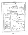
図2を参照すると、データキャプチャモジュール100を備えるデバイス101の例示的なブロック図が示される。デバイス101は、例示的な実施形態において、ハンズフリースキャナ、ハンドヘルドスキャナ、モバイルコンピュータなどであり得る。データ収集モジュール100は、1つの限定されない例示的な実施形態において、イメージスキャナモジュール100であり得る。イメージスキャナ100は、デバイス101に統合され得る。さらに、データキャプチャモジュール100は、デバイス101内にあるように示されるが、代替的な実施形態においては、データキャプチャモジュール100は、デバイス101に有線または無線で結合される分離したモジュールであり得る。例えば、一実施形態において、データキャプチャモジュール100は、コンピュータ101と結合されるコンパーチブルハンドヘルドの/据え付けのスキャンガンであり得る。
With reference to FIG. 2, an exemplary block diagram of a
イメージスキャナ100は、バス125によって一緒に結合された処理ユニット105と、スキャンモジュール115と、メモリ120と、通信インタフェース110と、イルミネーションモジュール140とを備えている。データキャプチャモジュール100のモジュールは、ソフトウェア、ハードウェア、ソフトウェアをエミュレートするハードウェア、および再プログラム可能なハードウェアの任意の組み合わせとしてインプリメントされ得る。バス125は、本発明の異なるモジュールの相互運用を示す例示的なバスである。設計選択の問題として、2つ以上のバスがあり得、一部の実施形態においては特定のモジュールがバス125と結合される代わりに、直接結合され得る。
The
処理ユニット105は、例示的な実施形態において、1つ以上の中央処理装置(CPU)、書き換え可能ゲートアレイ(FPGA)などとしてインプリメントされ得る。ある実施形態において、処理ユニット105は、メモリ120に格納されるソフトウェアおよび未加工のイメージを処理する汎用CPUを備え得る。他の実施形態において、処理ユニット105のモジュールは、例えば、信号処理、インタフェースエミュレーションなどの機能を実行するように処理ユニット105のメモリ内で予めプログラムされ得る。代替的な実施形態において、処理ユニット105の1つ以上のモジュールは、(例えば、メモリ120から)様々な処理を用いてロードされ得、複数の機能を行うFPGAとしてインプリメントされ得る。処理ユニット105は、上記のプロセッサの任意の組み合わせを備え得る。
The processing unit 105 may be implemented as one or more central processing units (CPUs), a rewritable gate array (FPGA), etc. in the exemplary embodiment. In certain embodiments, the processing unit 105 may comprise a general purpose CPU that processes software and raw images stored in the
スキャンモジュール115は、一実施形態において、光学モジュール130と、センサモジュール135と、ターゲッティングモジュール142とを備えるカメラ115としてインプリメントされ得る。光学モジュール130は、例えば、カメラ115のレンズ130であり得る。一部の実施形態において、光学モジュール130は2つ以上のレンズを備え得、2つ以上の焦点を提供し得る。さらに、光学モジュール130は、レンズには限定されず、イメージをキャプチャするために適した任意のプリズムおよび/または他の光学媒体が、光学モジュールをインプリメントするために使用され得る。
The
センサモジュール135は、一実施形態において、電荷結合デバイス(Charged−Coupled Device)(CCD)としてインプリメントされ得る。CCD135は、処理のためにデジタルフォーマットでイメージを記録する。代替的な実施形態において、イメージをキャプチャする任意のセンサが、使用され得、センサモジュール135(例えば、CMOS半導体)をインプリメントする。イルミネーションモジュール140は、限定されない一実施形態において、1つ以上の発光ダイオード(LED)145としてインプリメントされ得る。他のイルミネーション媒体が、代替的な実施形態において使用され得る。非対称のイルミネーションを提供するためのイルミネーション媒体の配置、数、および使用は、以下にさらに記載される。
The
本発明の一部の実施形態は、ターゲッティングモジュール142を備え得る。ターゲッティングモジュール142は、イメージスキャナ100の視野に近いターゲットを投影する、光源または複数の光源(例えば、レーザ)を備える。ターゲットは、スキャナの視野にデータフォームを配置することにおいてユーザを助け得る、十字線、正方形、円形、または任意の他のデザインとして対象上に現れる。
Some embodiments of the present invention may comprise a targeting
メモリ120は、揮発性メモリ、不揮発性メモリ、および再書き込み可能なメモリ(例えば、ランダムアクセスメモリ(RAM)、読み取り専用メモリ(ROM)および/またはフラッシュメモリ)としてインプリメントされ得る。メモリ120は、イメージスキャナ100を動作するために使用される方法および処理(例えば、信号処理方法150、電力管理方法155、インタフェース方法160および非対称のイルミネーションスキャン方法165)を格納する。メモリ120はまた、未加工のイメージデータおよび/または処理されたイメージデータを格納するために使用され得る。
デコード動作が開始される場合、例えば、トリガが押された場合には、スキャナ100は、非対称のイルミネーションスキャン方法165を開始する。本発明の一実施形態において、スキャナはスキャンモジュール115の片側からターゲットデータフォームを照らす。スキャンモジュール115は、スキャナ100の視野内のイメージをキャプチャし、イメージは、信号処理方法150によって解析され、デコードされる。
When the decoding operation is started, for example, when the trigger is pressed, the
図3は、本発明の実施形態に従ってインプリメントされた、例示的なスキャンモジュール300の前面図を示す。スキャンモジュール300は、カメラレンズ305と、イルミネーション媒体310と、ターゲッティングレンズ315とを備えている。イルミネーション媒体310(例えば、LED310)は、カメラレンズ305の左側に位置される。LED310からの光が、カメラレンズ305の片側から来るので、LED310は、デコード動作の間に、非対称にデータフォームを照らす。代替的な実施形態において、イルミネーションモジュール310は、カメラレンズ305の同じ側に位置されるLEDのグループを備え得る。例示的な実施形態において、レンズ305がデータフォームと一列に並んだ場合の角度で、ターゲットデータフォームを照らすように、LED310は位置される。LED310からの光は、斜めにデータフォームを照らすが、イルミネーション媒体および/またはスキャナは、データフォームに接触したり、極端に近付いたりする必要がない。
FIG. 3 shows a front view of an
別の実施形態において、スキャナ100の角度許容値を増加させるために、スキャンモジュール100は、カメラレンズ130とは異なる側に位置される追加のLED140を備え得る。対象の方向とスキャナの方向とは、動的であるので、データフォームによって作られるハイライトおよび/または影は、1つのイルミネーション角度から別の角度にかけてデコードし易くなり得る。代わりに使用される、拡散型のLEDは、スキャナ100が、異なる角度からデータフォームを非対称に照らすことを可能にする。データフォームの1つ以上のイメージが、各イルミネーション角度に対してキャプチャされ、一旦データフォームがうまくデコードされると、スキャナ100は、任意選択的にデコード動作を終了し得る。
In another embodiment, to increase the angle tolerance of the
図4は、本発明に従ってインプリメントされた、別の例示的なスキャンモジュール400の前面図を示す。スキャンモジュール300および400は、例示であり、スケールに合わせて描かれていない。スキャンモジュール400は、カメラレンズ405と、ターゲッティングレンズ410と、第1のイルミネーション媒体415(これはLED420および425のグループを備えている)と、第2のイルミネーション媒体430(これはLED435および440を備えている)とを備えている。
FIG. 4 shows a front view of another exemplary scan module 400 implemented in accordance with the present invention.
非対称のイルミネーションスキャン方法の例示的なデコード動作において、スキャンモジュール400は、第1のイルミネーション媒体415を用いてターゲットデータフォームの1つ以上のイメージをキャプチャし、解析する。スキャナ100が、キャプチャされたイメージを用いてデータフォームをうまくデコードしない場合には、スキャンモジュール400は、第2のイルミネーション媒体430を用いてデータフォームを照らし、追加のイメージをキャプチャし、解析する。データフォームおよび/またはスキャナ100が、第2のイルミネーション角度がデコードし易いイメージを生成するように位置されるので、第2のイルミネーション角度を用いて行われるデコード動作は、成功し得る。
In an exemplary decoding operation of the asymmetric illumination scan method, the scan module 400 uses a
図4に示される例示的な実施形態は、2つのイルミネーション媒体に限定はされない。複数のLEDまたはLEDのグループが、カメラレンズの周囲に位置され得る。さらに、イルミネーション媒体は、カメラレンズ405に対して対称的に配置される必要はない。イルミネーション媒体は、イルミネーション角度を変化させるようにカメラレンズ405から異なる距離に配置され得る。
The exemplary embodiment shown in FIG. 4 is not limited to two illumination media. Multiple LEDs or groups of LEDs may be located around the camera lens. Furthermore, the illumination medium need not be arranged symmetrically with respect to the
一部の実施形態において、スキャナ100の角度許容値は、イルミネーション媒体140を回転または旋回することを用いて増加し得る。スキャナ100は、各イルミネーション角度で、データフォームの1つ以上のイメージを得て、データフォームがうまく読み込まれた場合に、任意選択的に止まる。
In some embodiments, the angle tolerance of the
図2に戻って、データ収集モジュール100は、種々の言語で通信する異なるデバイス101に対するモジュールとしてインプリメントされ得る。それゆえ、データ収集モジュール100は、デコードされたデータフォームを、データ収集モジュール100とインタフェースするデバイス101の言語に翻訳するインタフェース方法160を包含する。異なるインタフェースは、汎用シリアルバス(USB)、スキャナエミュレーション、IBMキーボードウェッジ、シンボルシリアルインタフェース(SSI)などを含む。
Returning to FIG. 2, the
電力管理方法155は、スキャナ100によって使用される電力を管理する。一部の実施形態において、行動が所与の時間の間に検出されない場合には、スキャナ100は、電力セーブモードにスイッチし得る。電力セーブモードは、スキャナ100を完全にシャットダウンし得、あるいは該モードは、イメージキャプチャ速度を遅くし得、または他の電力セーブ手法を開始し得る。
The
図2の例示的な実施形態は、信号処理方法150と、非対称のイルミネーションスキャン方法165と、インタフェース方法160と、電力管理方法155とを別個の構成要素として図示するが、これらの方法はこの構成に限定されない。本明細書において記載される各方法は、全体または一部が、分離した構成要素であり得、または動作を相互運用し得、共有し得る。さらに、方法はメモリ120内に描かれるが、代替的な実施形態においては、方法は処理ユニット105のメモリ内に永久的にまたは動的に統合され得る。一部の実施形態において、スキャンモジュール115は、データキャプチャモジュール100から分離し得、データキャプチャモジュール100は、汎用コンピュータおよびソフトウェアを用いてインプリメントされ得る。
The exemplary embodiment of FIG. 2 illustrates the
メモリ120は、図2に単一のモジュールとして示されるが、一部の実施形態において、イメージスキャナ100は、2つ以上のメモリモジュールを備え得る。例えば、上記の方法は別個のメモリモジュール内に格納され得る。
Although the
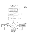
図5は、非対称のイルミネーションを用いてデータフォームをスキャンする方法500の例示的な実施形態を示している。イメージスキャナ100の参照が、方法500の記載においてなされる。方法500のステップおよび本明細書に記載される方法は、例示的であり、ステップの順序は設計選択の問題として再編成され得る。非対称のイルミネーションスキャン方法500は、開始ステップ205で開始する。例示的な実施形態において、イメージスキャナ100および/もしくはデバイス101が電力を受けた場合、ならびに/またはスキャナ100上のトリガもしくはボタンが押された場合に、方法500が開始する。デバイス101および/またはスキャナ100は、動作の前に診断を実行し得る。
FIG. 5 illustrates an exemplary embodiment of a
処理は、ステップ505からステップ510まで進み、ここでスキャナ100は、スキャンモジュールの側からターゲットデータフォームを照らす。図3のスキャンモジュール300は、スキャンモジュール300の片側に位置されるイルミネーション媒体310を有する例示的な構成を示す。スキャンモジュール300の片側からのイルミネーションは、本発明に従って、ターゲットデータフォームを非対称に照らす。
Processing proceeds from step 505 to step 510 where the
処理は、ステップ510からステップ515まで進み、ここでスキャナ100は、ターゲットデータフォームの表示(例えば、デジタルイメージ)をキャプチャする。次いで、ステップ520において、キャプチャされたイメージは解析され、ターゲットデータフォームはデコードされる。ステップ545において、デコードアルゴリズムが成功した場合には、処理はステップ555に進み、ここでデコードされたデータがさらに処理される。例えば、データは、デバイス101が解釈し得る言語に翻訳され得る。例えば、ステップ555において、イメージスキャナ100が、USB接続を介してコンピュータに取り付けられる場合には、デコードされたデータフォームは、シリアル形式に翻訳され、通信インタフェース110を介してデバイス101に通信される。ステップ555に続いて、方法500の処理はステップ560に進み、ここで方法500はステップ505に戻り、イメージスキャナ100は別のデータフォームを処理する準備が出来ている。
Processing proceeds from
ステップ545に戻って、スキャナ100がターゲットデータフォームのデコードを良好にしない場合には、処理はステップ550に進む。一部の実施形態においては、イメージスキャナ100は何もせず、ステップ560においてステップ505に戻るが、他の実施形態においては、スキャナ100はフェイル信号を通信インタフェース110に送信し得、および/または聞き取れるフェイルインジケータをスキャナ100のオペレータに発する。デバイス101は、聞き取れる音および/またはスクリーン上のメッセージを介して、フェイル信号を認識させ、オペレータに失敗を警告するようにプログラムされ得る。さらに、スキャナ100および/またはデバイス101は、データフォームをスキャナ100まで持ち上げるように、ならびに/もしくは異なる方向にスキャナおよび/または対象を傾けるように、オペレータに指示し得る。
Returning to step 545, if the
ステップ550に戻って、代替的な実施形態において、失敗したデコードの試行に応答して、ステップ560においてスキャナ100は、ステップ510に戻り、解析のためにターゲットデータフォームの別のピクチャを得る。スキャナ100は、失敗の前に予め決定された数の回数だけ試行し得る。他の実施形態において、2つ以上のイメージが並行して解析され得る。
Returning to step 550, in an alternative embodiment, in response to a failed decoding attempt, in step 560 the
図4に示されるように、スキャナ100は、2つ以上のイルミネーション媒体を備え得る。図6は、別の非対称のイルミネーションスキャン方法600を示し、ここでスキャナ100は、カメラレンズの左右に位置される2つのイルミネーション媒体を有するスキャンモジュールを備えている。
As shown in FIG. 4, the
非対称のスキャン方法600は、ステップ605において開始し、ここでスキャナ100は動作に入るようにトリガされ、および/または電力を受ける。ステップ610において、スキャナ100は、第1のイルミネーション媒体(例えば、イルミネーションモジュール1(415))を用いてターゲットデータフォームを照らす。代替的な実施形態において、方法600は、イルミネーションモジュール2(430)を有して開始し得るか、またはスキャナ100は、デコード動作ごとにイルミネーション媒体を交替し得る。
The asymmetric scanning method 600 begins at
処理は、ステップ610からステップ615に進み、ここでスキャナはデータフォームのデジタル表示をキャプチャし、ステップ620において、イメージがデコードされる。デコードが成功した場合には、処理はステップ625からステップ655まで進み、ここでデコードされたデータはさらに処理される。次いで、ステップ660において、スキャナ100は開始ステップ605に戻り、別のデータフォームのための準備が出来ている。
Processing proceeds from step 610 to step 615 where the scanner captures a digital representation of the data form and in
ステップ625に戻って、キャプチャされたデコードが成功しない場合には、処理はステップ625からステップ630まで進み、ここでスキャナ100はスキャンモジュール400の第2の側(例えば、イルミネーション媒体2(430))からターゲットデータフォームを照らす。ステップ635において、照らされるデータフォームのイメージは、キャプチャされ、ステップ640においてイメージがデコードされる。ステップ645において、デコードが成功した場合には、処理はステップ645からステップ655まで進み、ここでデコードされたデータはさらに処理される。次いで、ステップ660において、スキャナ100は開始ステップ605に戻り、別のデータフォームのための準備が出来ている。
Returning to step 625, if the captured decode is not successful, processing proceeds from
ステップ645に戻って、キャプチャされたイメージがうまくデコードされない場合には、処理は、フェイルステップ650に進む。ステップ650に続いて、一部の実施形態においては、ステップ660において方法600がステップ610に戻り、データフォームを再びデコードすることを試行する。このループは、所所の反復回数に対して、またはスキャナがうまくデータフォームをデコードするまで繰り返され得る。他の実施形態においては、ステップ660において、スキャナ100は開始ステップ605に戻る。
Returning to step 645, if the captured image is not successfully decoded, processing proceeds to fail step 650. Following step 650, in some embodiments, at
方法600の他の実施形態において、スキャナ100は、別のイルミネーションモジュールにスイッチする前に、予め決定された数の回数の間、同一のイルミネーションモジュールを用いて、イメージをキャプチャし、ターゲットデータフォームをデコードすることを試行し得る。
In another embodiment of the method 600, the
方法600に記載されるものと類似の方法が、イルミネーションモジュールを回転することを用いてスキャナ100が、角度許容値を増加させる実施形態において使用され得る。異なるイルミネーションソースを用いてイメージをキャプチャする代わりに、イルミネーション媒体を回転することによって、複数のイルミネーション角度が作られる。
A method similar to that described in method 600 can be used in embodiments in which
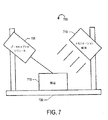
図7は、外部のイルミネーション媒体を有するデータキャプチャシステム700を備えている本発明の代替的な実施形態を示す。データキャプチャシステム700は、対象715に向けられたデータキャプチャモジュール705と、イルミネーション媒体710とを備えている。対象715は、DPMデータフォーム(例えば、2次元コード)を備えている。例示的な一実施形態において、データキャプチャシステム700は、組立ラインの一部である構造720に結合されている。対象がデータキャプチャモジュール705の視野を通過する場合に、イルミネーション媒体710によって、対象は照らされる。データキャプチャモジュール705は、通過する対象715上のデータフォームをキャプチャし、解析する。代替的な実施形態において、データキャプチャシステム700は、基底またはプラットフォーム備えている構造720を備え、ここに対象は解析のために位置され得る。
FIG. 7 illustrates an alternative embodiment of the present invention comprising a
一実施形態において、データキャプチャモジュール705は、イルミネーション媒体なしでDPMスキャナ705を用いてインプリメントされる。データフォームは、外部のイルミネーション媒体710によって照らされる。外部のイルミネーション媒体710は、連続モードの蛍光灯ライトボックス、LEDによって稼動されるフラッシュイルミネーションライトボックス、フラッシュランプなどとしてインプリメントされ得る。スキャナ705の視野を通過するDPMデータフォームを最適に照らすように、手動的におよび/または自動的に、外部イルミネーションは選択され、位置される。例えば、選択されるイルミネーション媒体は、点または拡散イルミネーションであり、イルミネーション媒体710は、非対称に、オンアクシスに、オフアクシスに、など位置され得る。さらに、代替的な実施形態において、データキャプチャシステム700は、複数のイルミネーション媒体を備え得、図6に描写される非対称のイルミネーションスキャン方法を実行し得る。
In one embodiment, the data capture module 705 is implemented using a DPM scanner 705 without an illumination medium. The data form is illuminated by an external illumination medium 710. The external illumination medium 710 may be implemented as a continuous mode fluorescent light box, a flash illumination light box operated by LEDs, a flash lamp, or the like. External illumination is selected and positioned manually and / or automatically to optimally illuminate the DPM data form passing through the field of view of scanner 705. For example, the selected illumination medium is a point or diffuse illumination, and the illumination medium 710 may be positioned asymmetrically, on-axis, off-axis, etc. Further, in an alternative embodiment, the
一部の実施形態において、同調イルミネーションを円滑にするために、スキャナ705は、イルミネーション媒体710と、有線、無線のいずれかによって別のコンピュータなどを介して結合される。スキャナ705がイメージを得る場合に、外部のイルミネーション媒体710のスイッチをオンする(turn on)制御信号を、スキャナ705は送信し得る。スキャナ705の露光設定は、イルミネーション制御信号よりもわずかに長くあり得、イルミネーション制御信号の遅延が、イルミネーション媒体710を、露光した期間外に活性化させないようにする。イルミネーション媒体のスイッチをオンおよびオフすることは、移動する対象上のデータフォームをフリーズさせるフラッシング効果を生じる。 In some embodiments, the scanner 705 is coupled to the illumination medium 710 via another computer, either wired or wireless, to facilitate tuned illumination. When the scanner 705 obtains an image, the scanner 705 may send a control signal to turn on the external illumination medium 710 (turn on). The exposure setting of the scanner 705 can be slightly longer than the illumination control signal, and the delay of the illumination control signal prevents the illumination medium 710 from being activated outside the exposure period. Switching the illumination media on and off creates a flushing effect that freezes the data form on the moving object.
一般的に利用可能なセンサは、CCDまたはCMOSセンサであり、世界中で一般的なテレビ信号規格に従って、しばしば、1秒ごとに25〜30フレームで最適に動作するように設計される。これらの速度で繰り返されるフラッシュイルミネーションは、フリッカ効果を示す傾向にある。しかし、一定に移動する組立ラインの環境のような環境に対しては、許容される最大速度で繰り返されるスキャンが、ある場合には望ましい。フリッカ効果を抑圧するための方法は、イルミネーションモジュールに、データキャプチャモジュールによってキャプチャされたイメージの数によって要求される数よりも多くのフラッシュを生成させることである。 Commonly available sensors are CCD or CMOS sensors, and are designed to operate optimally at 25-30 frames per second, often according to common television signal standards around the world. Flash illumination repeated at these rates tends to exhibit a flicker effect. However, for an environment such as a constantly moving assembly line environment, a scan that is repeated at the maximum speed allowed is desirable in some cases. A way to suppress the flicker effect is to cause the illumination module to generate more flash than required by the number of images captured by the data capture module.
本発明の実施形態はドットピーニングされたデータフォームをデコードするために記載されたが、本発明は、他のDPM手法(例えば、エッチング)によって作られるデータフォームと共に使用され得る。 Although embodiments of the present invention have been described for decoding dot-peened data forms, the present invention can be used with data forms created by other DPM techniques (eg, etching).
好ましい実施形態に適用された場合の本発明の基本的な新規な特徴が、示され、記載され、指摘されたが、開示された本発明の形成および詳細における様々な省略と置換と変化とが、本発明の精神から逸脱することなく当業者によってなされ得ることが理解される。それゆえ、本明細書に添付される特許請求の範囲によって示される限りにおいて限定されることが意図されている。 Although the basic novel features of the present invention as shown in the preferred embodiments have been shown, described and pointed out, various omissions, substitutions and changes in the form and details of the disclosed invention have been made. It will be understood that this can be done by one skilled in the art without departing from the spirit of the invention. Therefore, it is intended to be limited as indicated by the claims appended hereto.
Claims (27)
情報キャプチャモジュールの光学モジュールの第1の部分に位置する第1のナロービームイルミネーション媒体を用いて対象を照射するステップと、
該第1のナロービームイルミネーション媒体の該照射によって形成される該対象の第1の電子的な表現をキャプチャするステップと、
該対象の該第1の電子的な表現をデコードするステップと、
該デコードが成功しなかった場合に、該光学モジュールの第2の部分に位置する第2のナロービームイルミネーション媒体を用いて該対象を照射するステップであって、該第2のナロービームイルミネーション媒体からの該照射は、該第1のナロービームイルミネーション媒体からの該照射に対して非対称的である、ステップと、
該第2のナロービームイルミネーション媒体の該照射によって形成される該対象の第2の電子的な表現をキャプチャするステップと、
該対象の該第2の電子的な表現をデコードするステップと
を包含する、方法。An asymmetric illumination method,
A step of irradiating an object by using a first narrow beam illumination medium positioned on the first portion of the optical module information capturing module,
Capturing a first electronic representation of the object formed by the irradiation of the first narrow beam illumination medium ;
Decoding the first electronic representation of the object;
In a case where the decoding is not successful, a step of irradiating the object by using a second narrow beam illumination medium located in the second portion of the optical module, from the narrow beam illumination medium of the second The irradiation of is asymmetric with respect to the irradiation from the first narrow beam illumination medium; and
Capturing a second electronic representation of the object formed by the irradiation of the second narrow beam illumination medium ;
Comprising a step of decoding an electronic representation of the second of said subject method.
各イルミネーションを用いて前記対象のさらなる電子的な表現をキャプチャするステップと、
該対象の該キャプチャされたさらなる電子的な表現をデコードするステップと
をさらに包含する、請求項8に記載の方法。Alternately irradiating each of the plurality of illumination media;
Capturing a further electronic representation of the object using each illumination;
9. The method of claim 8 , further comprising: decoding the captured additional electronic representation of the object.
情報キャプチャモジュールの光学モジュールの片側の該第1のナロービームイルミネーション媒体を用いて対象を照射することであって、該第1のナロービームイルミネーション媒体は、軸の周りを回転する、ことと、
該第1のナロービームイルミネーション媒体の該照射によって形成される該対象の第1の電子的な表現をキャプチャすることと、
該対象の該第1の電子的な表現をデコードすることと、
該デコードが成功しなかった場合に、該光学モジュールの別の側に位置する第2のナロービームイルミネーション媒体を用いて該対象を照射することであって、該第2のナロービームイルミネーション媒体は、該軸の周りを回転し、該第2のナロービームイルミネーション媒体からの該照射は、該第1のナロービームイルミネーション媒体からの該照射に対して非対称的である、ことと、
該第2のナロービームイルミネーション媒体の該照射によって形成される該対象の第2の電子的な表現をキャプチャすることと、
該対象の該第2の電子的な表現をデコードすることと
を包含する、方法。 Rotating the first narrow beam illumination medium to a first angle;
The method comprising irradiating a subject using narrow beam illumination medium on one side of the first optical module information capturing module, said first narrow beam illumination medium rotates about an axis, and that,
The method comprising capturing a first electronic representation of said object formed by said radiation of said first narrow beam illumination medium,
And decoding the said first electronic representation of said object,
If the decoding is unsuccessful, illuminating the object with a second narrow beam illumination medium located on another side of the optical module, the second narrow beam illumination medium comprising: Rotating about the axis, the illumination from the second narrow beam illumination medium being asymmetric with respect to the illumination from the first narrow beam illumination medium;
Capturing a second electronic representation of the object formed by the irradiation of the second narrow beam illumination medium;
Decoding the second electronic representation of the object .
該第3のイルミネーション角度で、該第1のナロービームイルミネーション媒体を用いて、前記対象を照射するステップと、
該対象の第3の電子的な表現をキャプチャするステップと、
該対象の該キャプチャされた第3の電子的な表現をデコードするステップと
をさらに包含する、請求項11に記載の方法。Rotating the first narrow beam illumination medium to a third angle;
A step in illumination angle of said third, using the first narrow beam illumination medium, illuminating said object,
Capturing a third electronic representation of the object;
The method of claim 11 , further comprising: decoding the captured third electronic representation of the object.
該複数のイルミネーション角度で、該第1のナロービームイルミネーション媒体を用いて前記対象を照射するステップと、
各イルミネーション角度で、該対象のさらなる電子的な表現をキャプチャするステップと、
該対象の該キャプチャされたさらなる電子的な表現をデコードするステップと
をさらに包含する、請求項11に記載の方法。Rotating the first narrow beam illumination medium to a plurality of angles;
In illumination angle of the plurality of the steps of illuminating said object using said first narrow beam illumination medium,
Capturing a further electronic representation of the object at each illumination angle;
The method of claim 11 , further comprising: decoding the captured additional electronic representation of the object.
処理ユニットと、
スキャンモジュールと、
第1の位置に位置する第1のイルミネーション媒体と、
第2の位置に位置する第2のイルミネーション媒体であって、該第2のイルミネーション媒体からの照射は、該第1のイルミネーション媒体からの照射に対して非対称的である、第2のイルミネーション媒体と、
該情報キャプチャデバイス上で動作可能な少なくとも1つの処理を格納するメモリと
を備えており、
該少なくとも1つの処理は、
該第1のイルミネーション媒体を用いて対象を照射することと、
該第1のイルミネーション媒体の該照射によって形成される該対象の第1の電子的な表現をキャプチャすることと、
該対象の該第1の電子的な表現をデコードすることと、
該デコードが成功しなかった場合に、該第2のイルミネーション媒体を用いて該対象を照射することと、
該第2のイルミネーション媒体の該照射によって形成された該対象の第2の電子的な表現をキャプチャすることと、
該対象の該第2の表現をデコードすることと
を包含する、情報キャプチャデバイス。An information capture device,
A processing unit;
A scan module;
A first illumination medium located at a first position;
A second illumination medium located at a second position, wherein the illumination from the second illumination medium is asymmetric with respect to the illumination from the first illumination medium; ,
A memory for storing at least one process operable on the information capture device,
The at least one process is:
Irradiating an object with the first illumination medium;
The method comprising capturing a first electronic representation of said object formed by said radiation of the first illumination medium,
Decoding the first electronic representation of the object;
In a case where the decoding is not successful, the method comprising: irradiating the object using a second illumination medium,
The method comprising capturing a second electronic representation of said object formed by said radiation of the second illumination medium,
It encompasses and decoding the second representation of the object, the information capture device.
前記複数のさらなるイルミネーション媒体の各々を交互に照射するステップと、
各イルミネーションを用いて前記対象のさらなる電子的な表現をキャプチャするステップと、
該対象の該キャプチャされたさらなる電子的な表現をデコードするステップと
をさらに包含する、請求項21に記載の情報キャプチャデバイス。The at least one process includes
Alternately irradiating each of the plurality of further illumination media;
Capturing a further electronic representation of the object using each illumination;
The information capture device of claim 21 , further comprising: decoding the captured additional electronic representation of the object.
処理ユニットと、
スキャンモジュールと、
該スキャンモジュールの第1の部分に位置する第1のイルミネーション媒体であって、軸の周りを回転する第1のイルミネーション媒体と、
該情報キャプチャデバイス上で動作可能な少なくとも1つの処理を格納するメモリと
を備えており、
該少なくとも1つの処理は、
該第1のイルミネーション媒体を用いて対象を照射することと、
該第1のイルミネーション媒体の該照射によって形成された該対象の第1の電子的な表現をキャプチャすることと、
該第1の電子的な表現をデコードすることと、
該デコードが成功しなかった場合に、該スキャンモジュールの第2の部分に位置する第2のイルミネーション媒体を用いて該対象を照射することであって、該第2のイルミネーション媒体は、該軸の周りを回転し、該第2のイルミネーション媒体からの該照射は、該第1のイルミネーション媒体からの該照射に対して非対称的である、ことと、
該第2のイルミネーション媒体の該照射によって形成される該対象の第2の電子的な表現をキャプチャすることと、
該対象の該第2の電子的な表現をデコードすることと
を包含する、情報キャプチャデバイス。An information capture device,
A processing unit;
A scan module;
A first illumination medium positioned on the first portion of the scan module, a first illumination medium rotates about an axis,
A memory for storing at least one process operable on the information capture device,
The at least one process is:
And irradiating the subject using the first illumination medium,
The method comprising capturing a first electronic representation of said object formed by said radiation of the first illumination medium,
And decoding the said first electronic representation,
If the decoding is unsuccessful, illuminating the object with a second illumination medium located in a second portion of the scan module, the second illumination medium comprising: Rotating around and the illumination from the second illumination medium is asymmetric with respect to the illumination from the first illumination medium;
Capturing a second electronic representation of the object formed by the irradiation of the second illumination medium;
Decoding the second electronic representation of the object .
前記第1のイルミネーション媒体を第2の角度まで回転させるステップと、
該第2のイルミネーション角度で、該第1のイルミネーション媒体を用いて前記対象を照射するステップと、
該対象の第2の電子的な表現をキャプチャするステップと、
該対象の該第2の電子的な表現をデコードするステップと
をさらに包含する、請求項24に記載の情報キャプチャデバイス。The at least one process includes
Rotating the first illumination medium to a second angle;
In illumination angle of the second, and the step of irradiating the object by using the first illumination medium,
Capturing a second electronic representation of the object;
The information capture device of claim 24 , further comprising: decoding the second electronic representation of the object.
前記第1のイルミネーション媒体を複数の角度まで回転させるステップと、
該複数のイルミネーション角度で該第1のイルミネーション媒体を用いて前記対象を照射するステップと、
各イルミネーション角度で該対象のさらなる電子的な表現をキャプチャするステップと、
該対象の該キャプチャされた電子的な表現をデコードするステップと
をさらに包含する、請求項24に記載の情報キャプチャデバイス。The at least one process includes
Rotating the first illumination medium to a plurality of angles;
A step of irradiating the object with illumination angle the plurality of by using the first illumination medium,
Capturing a further electronic representation of the object at each illumination angle;
25. The information capture device of claim 24 , further comprising: decoding the captured electronic representation of the object.
Applications Claiming Priority (2)
| Application Number | Priority Date | Filing Date | Title |
|---|---|---|---|
| US11/027,733 US7281662B2 (en) | 2004-12-30 | 2004-12-30 | Methods and apparatus for information capture illumination |
| PCT/US2005/044223 WO2006073660A2 (en) | 2004-12-30 | 2005-12-06 | Methods and apparatus for information capture illumination |
Publications (2)
| Publication Number | Publication Date |
|---|---|
| JP2008527492A JP2008527492A (en) | 2008-07-24 |
| JP4589409B2 true JP4589409B2 (en) | 2010-12-01 |
Family
ID=36639246
Family Applications (1)
| Application Number | Title | Priority Date | Filing Date |
|---|---|---|---|
| JP2007549403A Active JP4589409B2 (en) | 2004-12-30 | 2005-12-06 | Method and apparatus for information capture illumination |
Country Status (5)
| Country | Link |
|---|---|
| US (2) | US7281662B2 (en) |
| EP (1) | EP1831816B1 (en) |
| JP (1) | JP4589409B2 (en) |
| CN (1) | CN101095147B (en) |
| WO (1) | WO2006073660A2 (en) |
Families Citing this family (13)
| Publication number | Priority date | Publication date | Assignee | Title |
|---|---|---|---|---|
| US20030222147A1 (en) * | 2002-06-04 | 2003-12-04 | Hand Held Products, Inc. | Optical reader having a plurality of imaging modules |
| US8403225B2 (en) * | 2006-11-17 | 2013-03-26 | Hand Held Products, Inc. | Vehicle license plate indicia scanning |
| US8556180B2 (en) * | 2009-10-13 | 2013-10-15 | Marson Technology Co., Ltd. | Multiwavelength barcode reader |
| IT1397388B1 (en) * | 2009-12-29 | 2013-01-10 | Datalogic Mobile S R L | PORTABLE DEVICE AND METHOD FOR READING CODIFIED INFORMATION |
| US8442297B2 (en) * | 2010-02-23 | 2013-05-14 | Arinc Incorporated | Methods of evaluating the quality of two-dimensional matrix dot-peened marks on objects and mark verification systems |
| US9418270B2 (en) | 2011-01-31 | 2016-08-16 | Hand Held Products, Inc. | Terminal with flicker-corrected aimer and alternating illumination |
| US8602308B2 (en) * | 2011-12-22 | 2013-12-10 | Symbol Technologies, Inc. | Imaging device having light field sensor |
| DE102012018388B4 (en) * | 2012-09-18 | 2014-06-26 | Knapp Ag | Device for detecting a code on an article, preferably at the goods receipt of a picking system |
| CN105225523B (en) * | 2015-10-15 | 2018-01-02 | 浙江宇视科技有限公司 | A kind of parking space state detection method and device |
| US9811705B1 (en) | 2016-05-10 | 2017-11-07 | Datalogic Ip Tech S.R.L. | Illumination system with active element for generating different illumination patterns for a data reader |
| US10628646B1 (en) | 2017-12-29 | 2020-04-21 | Cognex Corporation | Off-axis dual-sensor vision system camera and method for using the same |
| US11481568B1 (en) | 2017-12-29 | 2022-10-25 | Cognex Corporation | Dome illuminator for vision system camera and method for using the same |
| US11809949B2 (en) * | 2021-04-30 | 2023-11-07 | Zebra Technologies Corporation | Systems and methods to optimize imaging settings and image capture for a machine vision job |
Family Cites Families (18)
| Publication number | Priority date | Publication date | Assignee | Title |
|---|---|---|---|---|
| JPS5317454B2 (en) * | 1973-08-22 | 1978-06-08 | ||
| JPS60144884A (en) * | 1983-12-31 | 1985-07-31 | Nippon Steel Corp | Detecting method of printed letter |
| JPS60207980A (en) * | 1984-03-31 | 1985-10-19 | Tokinaa Kogaku Kk | Method and device for fetching picture |
| JPS6180372A (en) * | 1984-09-26 | 1986-04-23 | Nippon Steel Corp | Detecting method of dotted print |
| JPS63126081A (en) * | 1986-11-14 | 1988-05-30 | Nippon Steel Corp | Detecting method for print |
| JP2959035B2 (en) * | 1990-03-26 | 1999-10-06 | オムロン株式会社 | Embossed image reader |
| JPH0562012A (en) * | 1991-08-30 | 1993-03-12 | Nisca Corp | Method and device for reading ruggedness information |
| JPH05290213A (en) * | 1992-04-13 | 1993-11-05 | Hitachi Eng Co Ltd | Method and device for processing image |
| US5515452A (en) * | 1992-12-31 | 1996-05-07 | Electroglas, Inc. | Optical character recognition illumination method and system |
| JPH06203206A (en) * | 1993-01-07 | 1994-07-22 | Oki Electric Ind Co Ltd | Image reader for card |
| JPH06266890A (en) * | 1993-03-17 | 1994-09-22 | Dainippon Printing Co Ltd | Embossed character recognizing device |
| US5648650A (en) * | 1994-09-07 | 1997-07-15 | Alps Electric Co., Ltd. | Optical bar code reading apparatus with regular reflection detecting circuit |
| JPH09218910A (en) * | 1996-02-08 | 1997-08-19 | Toshiba Corp | Method and device for reading marking |
| JP3280892B2 (en) * | 1997-09-30 | 2002-05-13 | 富士通株式会社 | Optical scanning device |
| EP2093694B1 (en) * | 2000-10-26 | 2011-06-22 | Datalogic S.p.A. | Receiving chamber for a laser reader |
| JP2003022414A (en) * | 2001-07-06 | 2003-01-24 | Sony Corp | Bar code reader |
| NO20023090L (en) * | 2002-06-26 | 2003-12-29 | Tomra Systems Asa | Device for recognizing containers |
| US7028901B2 (en) * | 2003-07-17 | 2006-04-18 | Symbol Technologies, Inc. | System and method for reading and decoding optical codes using multiple color illumination |
-
2004
- 2004-12-30 US US11/027,733 patent/US7281662B2/en active Active
-
2005
- 2005-12-06 WO PCT/US2005/044223 patent/WO2006073660A2/en active Application Filing
- 2005-12-06 EP EP05853210A patent/EP1831816B1/en active Active
- 2005-12-06 JP JP2007549403A patent/JP4589409B2/en active Active
- 2005-12-06 CN CN2005800457177A patent/CN101095147B/en active Active
-
2007
- 2007-09-14 US US11/855,285 patent/US7543754B2/en active Active
Also Published As
| Publication number | Publication date |
|---|---|
| EP1831816B1 (en) | 2012-07-25 |
| US20080000978A1 (en) | 2008-01-03 |
| WO2006073660A3 (en) | 2006-10-05 |
| US7543754B2 (en) | 2009-06-09 |
| EP1831816A4 (en) | 2009-12-02 |
| CN101095147B (en) | 2010-05-12 |
| WO2006073660A2 (en) | 2006-07-13 |
| US7281662B2 (en) | 2007-10-16 |
| EP1831816A2 (en) | 2007-09-12 |
| US20060144945A1 (en) | 2006-07-06 |
| CN101095147A (en) | 2007-12-26 |
| JP2008527492A (en) | 2008-07-24 |
Similar Documents
| Publication | Publication Date | Title |
|---|---|---|
| JP4589409B2 (en) | Method and apparatus for information capture illumination | |
| US6688523B1 (en) | System for reading optical indicia | |
| US7261238B1 (en) | Method of locating imaged bar codes for an imaging-based bar code reader | |
| CN110532822B (en) | Multiple imaging assemblies for readers | |
| EP0980537B1 (en) | Optical scanner and image reader for reading images and decoding optical information including one and two dimensional symbologies at variable depth of field | |
| US9465967B2 (en) | Apparatus comprising light sensing assemblies with range assisted gain control | |
| US5500516A (en) | Portable oblique optical reader system and method | |
| US7322526B1 (en) | System for reading optical indicia | |
| EP1854044A2 (en) | Methods and apparatus for improving direct part mark scanner performance | |
| GB2518284A (en) | System and method for selectively reading code symbols | |
| US7264168B2 (en) | Asymmetrical scanner | |
| CA2157134A1 (en) | Portable optical reader system and method | |
| CN108351955B (en) | Compact imaging module with rangefinder | |
| JP2008518353A (en) | Method and apparatus for dynamic signal processing | |
| US20090084855A1 (en) | Methods and Apparatus for Directing Bar Code Positioning for Imaging Scanning | |
| US6974085B1 (en) | System for reading optical indicia | |
| US7571855B2 (en) | Display with symbology | |
| JP2005122355A (en) | Optical information reader | |
| US11308295B2 (en) | Handheld optical information reading device | |
| EP1916557B1 (en) | Optical scanner and image reader for reading images and decoding optical information including one and two dimensional symbologies at variable depth of field | |
| CA2577235A1 (en) | Optical scanner and image reader for reading images and decoding optical information including one and two dimensional symbologies at variable depth of field | |
| CN1084991A (en) | Enlarge the photoscanner of depth of focus | |
| JP2008176636A (en) | Optical information reading apparatus |
Legal Events
| Date | Code | Title | Description |
|---|---|---|---|
| A131 | Notification of reasons for refusal |
Free format text: JAPANESE INTERMEDIATE CODE: A131 Effective date: 20100326 |
|
| A601 | Written request for extension of time |
Free format text: JAPANESE INTERMEDIATE CODE: A601 Effective date: 20100624 |
|
| A602 | Written permission of extension of time |
Free format text: JAPANESE INTERMEDIATE CODE: A602 Effective date: 20100701 |
|
| A521 | Request for written amendment filed |
Free format text: JAPANESE INTERMEDIATE CODE: A523 Effective date: 20100722 |
|
| TRDD | Decision of grant or rejection written | ||
| A01 | Written decision to grant a patent or to grant a registration (utility model) |
Free format text: JAPANESE INTERMEDIATE CODE: A01 Effective date: 20100819 |
|
| A01 | Written decision to grant a patent or to grant a registration (utility model) |
Free format text: JAPANESE INTERMEDIATE CODE: A01 |
|
| A61 | First payment of annual fees (during grant procedure) |
Free format text: JAPANESE INTERMEDIATE CODE: A61 Effective date: 20100909 |
|
| R150 | Certificate of patent or registration of utility model |
Ref document number: 4589409 Country of ref document: JP Free format text: JAPANESE INTERMEDIATE CODE: R150 Free format text: JAPANESE INTERMEDIATE CODE: R150 |
|
| FPAY | Renewal fee payment (event date is renewal date of database) |
Free format text: PAYMENT UNTIL: 20130917 Year of fee payment: 3 |
|
| R250 | Receipt of annual fees |
Free format text: JAPANESE INTERMEDIATE CODE: R250 |
|
| R250 | Receipt of annual fees |
Free format text: JAPANESE INTERMEDIATE CODE: R250 |
|
| R250 | Receipt of annual fees |
Free format text: JAPANESE INTERMEDIATE CODE: R250 |
|
| R250 | Receipt of annual fees |
Free format text: JAPANESE INTERMEDIATE CODE: R250 |
|
| S531 | Written request for registration of change of domicile |
Free format text: JAPANESE INTERMEDIATE CODE: R313531 |
|
| S533 | Written request for registration of change of name |
Free format text: JAPANESE INTERMEDIATE CODE: R313533 |
|
| R350 | Written notification of registration of transfer |
Free format text: JAPANESE INTERMEDIATE CODE: R350 |
|
| RD02 | Notification of acceptance of power of attorney |
Free format text: JAPANESE INTERMEDIATE CODE: R3D02 |
|
| R250 | Receipt of annual fees |
Free format text: JAPANESE INTERMEDIATE CODE: R250 |
|
| R250 | Receipt of annual fees |
Free format text: JAPANESE INTERMEDIATE CODE: R250 |
|
| R250 | Receipt of annual fees |
Free format text: JAPANESE INTERMEDIATE CODE: R250 |
|
| R250 | Receipt of annual fees |
Free format text: JAPANESE INTERMEDIATE CODE: R250 |
|
| R250 | Receipt of annual fees |
Free format text: JAPANESE INTERMEDIATE CODE: R250 |
|
| R250 | Receipt of annual fees |
Free format text: JAPANESE INTERMEDIATE CODE: R250 |
|
| R250 | Receipt of annual fees |
Free format text: JAPANESE INTERMEDIATE CODE: R250 |