JP4587280B2 - Ring earrings - Google Patents
Ring earrings Download PDFInfo
- Publication number
- JP4587280B2 JP4587280B2 JP2004177985A JP2004177985A JP4587280B2 JP 4587280 B2 JP4587280 B2 JP 4587280B2 JP 2004177985 A JP2004177985 A JP 2004177985A JP 2004177985 A JP2004177985 A JP 2004177985A JP 4587280 B2 JP4587280 B2 JP 4587280B2
- Authority
- JP
- Japan
- Prior art keywords
- shaped
- ring
- arc
- recess
- pair
- Prior art date
- Legal status (The legal status is an assumption and is not a legal conclusion. Google has not performed a legal analysis and makes no representation as to the accuracy of the status listed.)
- Expired - Fee Related
Links
Images


Landscapes
- Adornments (AREA)
Description
この発明はリング状耳飾りに関し、長時間使用しても痛くならない上、簡単に耳たぶから外れることのない耳飾りを提供しようとするものである。 The present invention relates to a ring-shaped earring that is intended to provide an earring that does not hurt even when used for a long time and does not easily come off the earlobe.
従来、リング状耳飾りとしては図6ないし図8に示すものが主流である。
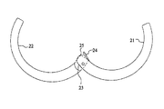
1)図6のように、一対の挟着部材21,22を連結する連結部分において、その一方の挟着部材21に設けた軸受部23の内側にバネ板24を取り付け、他方の挟着部材22に設けた回転部25の端部に上記バネ板24が係合して、上記挟着部材21,22を耳たぶを挟み付ける方向に板バネ24で付勢するようにしたもの(実用新案登録第366337号公報・・・特許文献1、特開平7−327715号公報・・・特許文献2、特開平10−257908号公報・・・特許文献3、特開2001−61519号公報・・・特許文献4、特開2001−104024号公報・・・特許文献5、特開2002−165619号公報・・・特許文献6、登録実用新案第3095482号公報・・・特許文献7をそれぞれ参照)。その他コイル状バネを用いた例もある。
2)図7のように、一対の挟着部材31,32を連結する連結部分において、その一方の挟着部材31に設けた軸受部33と他方の挟着部材32に設けた回転部34とに取り付けた連結軸35を単にかしめ付けただけのもの(特開平9−289910号公報・・・特許文献8、特開平11−235214号公報・・・特許文献9をそれぞれ参照)。
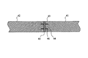
3)図8のように、一対の挟着部材41,42を連結する連結部分において、その一方の挟着部材41に設けた軸受部43と他方の挟着部材42に設けた回転部44とに取り付けた連結軸45をワッシャ類46を介してかしめ付けたもの(特開平10−276810号公報・・・特許文献10、特開2000−116417号公報・・・特許文献11、特開2000−229007号公報・・・特許文献12、特開2000−253914号公報・・・特許文献12、特開2003−210219号公報・・・特許文献13をそれぞれ参照)。
1) As shown in FIG. 6, in a connecting portion for connecting a pair of
2) As shown in FIG. 7, in the connecting portion that connects the pair of
3) As shown in FIG. 8, in the connecting portion that connects the pair of
しかしながら上記従来例の1)においては、バネ弾性を利用するものであって開閉動作にメリハリがあって使いやすい反面、バネ材で常に挟み付ける方向に力が掛かっているため、長時間使用すると耳たぶが痛くなってしまうという欠点があった。 However, in the above conventional example 1), the spring elasticity is utilized and the opening / closing operation is sharp and easy to use. On the other hand, the force is always applied in the direction in which the spring material is sandwiched. Had the disadvantage of becoming painful.
また、従来例の2)においては、耳飾りの素材自体が柔らかいものであるために係合部分がギスギスして動きがスムーズでなく、かしめる力がかた過ぎたり、ゆるくてすぐに開き、耳たぶから落ちやすいかのどちらかであった。 Further, in the conventional example 2), since the material of the earring itself is soft, the engaging portion is distorted and the movement is not smooth, the caulking force is too strong, and the earpiece is loose and immediately opens. It was either easy to fall off.
従来例の3)は近年主流となってきているが、例えばステンレス製の硬質パッキング(ワッシャ)を介在させることは逆に動きがスムーズであることにつながり、一定のグリップ力ではさみ込む金具の方式としては上記2)の方式と同じで安心できない。また、上記2)と同様に何回か動かしているとすぐにかしめ部分がゆるくなって信頼して使用することができない。 The conventional example 3) has become the mainstream in recent years. For example, the intervention of a stainless steel hard packing (washer) leads to smooth movement, and a method of fitting with a certain grip force. Is the same as the above method 2) and cannot be relieved. In addition, as in the case 2), if it is moved several times, the caulking portion becomes loose immediately and cannot be used reliably.
この発明のリング状耳飾りは従来例の上記欠点を解消しようとするものであり、長時間使用しても痛くならない上、簡単に耳たぶから外れることのないリング状耳飾りを提供しようとするものである。 The ring-shaped earring of the present invention is intended to eliminate the above-mentioned drawbacks of the conventional example, and is intended to provide a ring-shaped earring that does not hurt even when used for a long time and does not easily come off the earlobe. .
すなわちこの発明のリング状耳飾りは、一対の円弧状部材を対向させて、その一方の円弧状部材の連結部分には軸受部を、他方の円弧状部材の連結部分には回転部を設けるとともに連結軸で連結し、円弧状部材の他端を開閉可能としたリング状耳飾りであって、前記回転部を延長して先端に突起を設けた係合部を形成し、また前記回転部側面の連結軸の周囲に沿って筒状の連結ガイドを形成し、前記軸受部には内方に向けて前記係合部を収納する凹部を設け、前記凹部の内奥部分には所定長さのすり割を形成し、さらに前記係合部と凹部との間にコ字状の硬質パッキングを介在させるとともに、該コ字状の硬質パッキングには前記連結ガイドと突起とに対応する取付孔を設けることにより、前記硬質パッキングを前記係合部の両側に保持して、前記凹部の内壁と上記係合部の外壁とを前記硬質パッキングを介して係合させることにより、上記一対の円弧状部材の回転を規制させ、耳飾りの耳たぶからの脱落を防止したことを特徴とするものである。 That is, in the ring-shaped earring of the present invention, a pair of arc-shaped members are opposed to each other, and a connecting portion of one arc-shaped member is provided with a bearing portion, and a connecting portion of the other arc-shaped member is provided with a rotating portion and connected. coupled with the shaft, a ring-shaped earrings which enables opening and closing the other end of the arc-shaped member, by extending the pre-Symbol rotation unit to form an engaging portion provided with a protrusion at the tip, also of the rotating portion side along the periphery of the connecting shaft to form a tubular coupling guide, said bearing portion a recess for accommodating the engaging portion toward the inside, the inner back fixed length is at the portion of the front Symbol recess The U-shaped hard packing is interposed between the engaging portion and the recess, and the U-shaped hard packing has mounting holes corresponding to the connection guide and the protrusion. By providing the hard packing on both sides of the engaging portion The Rukoto the inner and outer walls of the engaging portions of the front Symbol recess is engaged through the rigid packing, to restrict the rotation of the pair of arcuate members, that it has prevented from falling out of the ear lobe earrings It is a feature.
この発明のリング状耳飾りは上述のように構成したので、着用時に挟持体には耳たぶを挟み付ける方向にほとんど力がかからないため、リング状耳飾りを長時間使用しても痛くなることがない。 Since the ring-shaped earring according to the present invention is configured as described above, there is almost no force in the direction in which the earlobe is sandwiched between the sandwiched body when worn, so that even if the ring-shaped earring is used for a long time, there is no pain.
しかも、簡単に耳たぶから外れることがなく、耳たぶへの着脱も非常に簡単に行なうことができる。 In addition, the earlobe is not easily detached and can be easily attached to and detached from the earlobe.
また、構造が簡単で製造が容易であり、しかも耳たぶを挟み付ける力の調節や緩んだ際の締め直しも簡単に行なうことができる。もちろん、構造が簡単なためにコスト的にも下げやすいリング状耳飾りを提供することができるようになった。 Further, the structure is simple and the manufacturing is easy, and the adjustment of the force for pinching the earlobe and the retightening when loosened can be easily performed. Of course, it is possible to provide a ring-shaped earring that is easy to lower because of its simple structure.
以下、図面に基づき、この発明のリング状耳飾りの実施の形態について説明する。
図1はこの発明のリング状耳飾りの1実施例を示す分解斜視図、図2は連結部分のかしめ付け作業前の状態を示す要部断面図、図3はかしめ付け作業後の状態を示す要部断面図、図4は組み付け状態を示す側面図、図5は一対の円弧状部材を開いた状態の側面図である。
Hereinafter, embodiments of the ring-shaped earring of the present invention will be described with reference to the drawings.
FIG. 1 is an exploded perspective view showing an embodiment of a ring-shaped earring according to the present invention, FIG. 2 is a cross-sectional view of a main portion showing a state before a connecting portion is caulked, and FIG. 3 is a view showing a state after the caulking operation. FIG. 4 is a side view showing the assembled state, and FIG. 5 is a side view showing a state in which a pair of arcuate members are opened.
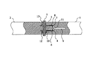
図1ないし図3に示すように、対向する一対の円弧状部材1,2において、一方の円弧状部材1の連結部分には軸受部3が、他方の円弧状部材2の連結部分には回転部4が設けられ、両者は連結軸5で回動自在に連結されている。そして、円弧状部材1,2の他端は開閉可能となっている。
As shown in FIG. 1 to FIG. 3, in a pair of opposing arc-
また、上記回転部4には延長されて係合部6が形成してあり、他方、上記軸受部3には内方に向けて係合部6を収納する凹部7が設けてある。すなわち、軸受部3の凹部7内に係合部6を収納するとともに、軸受部3と回転部4の両者の軸孔に連結軸5を挿通してその両端をかしめ付けることにより、一対の円弧状部材1,2が組み付けられるのである。
図において8は、上記係合部6と凹部7との間に介在させたコ字状の硬質パッキングで、上記凹部7の内壁と上記係合部6の外壁とが硬質パッキング8を介して係合することにより、上記一対の円弧状部材1,2の回転を規制させ、耳飾りの耳たぶからの脱落を防止しているのである。
The rotating portion 4 is extended to form an
In the figure,
すなわち、上記凹部7の内壁と上記係合部6の外壁とが硬質パッキング8を介して係合しており、一対の円弧状部材1,2の回転を規制する際に、凹部7が弾性力を持って係合部6をはさみ付けることになる。それゆえ、耳飾りの耳たぶからの脱落を確実に防止することができ、図4の閉じた位置と、図5の開いた位置との間を開閉動作させる際の、回転部4の動きも極めてスムーズなものとなる。
なお、上記係合部6を先端に向かって幅広となるテーパ状にしておき、幅広部分で凹部7と係合させることにより、一対の円弧状部材1,2の回転を規制する際に、凹部7によって係合部6をはさみ付ける弾性力を最大限に活用することができる。
That is, the inner wall of the concave portion 7 and the outer wall of the
The
回転部4側面の連結軸5の周囲に沿って筒状の連結ガイド10を形成し、また係合部6先端には突起11を形成してあるので、予めコ字状の硬質パッキング8に上記連結ガイド10と突起11とに対応して取付孔を設けておくことにより、この取付孔に連結ガイド10と突起11をはめ込むだけで、硬質パッキング8は係合部6の両側にワンタッチで取り付けることができ、かつ使用中に外れたりすることのないよう確実に保持される。
Since the
図のように、上記凹部7には内奥にはさらに所定長さのすり割9が形成してある。こうすることにより、もともと回転部4を収納するための凹部7の存在によって軸受部3に作用している弾性力を、すり割9の作用でより大きくすることができる。したがって、軸受部3の凹部7が弾性力を持って係合部6をはさみ付ける際の作用効果を増大させるので、耳飾りの耳たぶからの脱落を確実に防止することができ、また回転部4の動きも極めてスムーズなものとなる。
As shown in the figure, a slit 9 having a predetermined length is further formed in the recess 7 at the inner back. By doing so, the elastic force acting on the
上記回転部4における連結軸5の周囲に沿って形成した筒状の連結ガイド10を、軸受部3の内側に設けた凹溝12にはめ込むことにより、連結ガイド10と凹溝12の両者を組み付けているので、一対の円弧状部材1,2の連結をこの連結ガイド10と凹溝12との係合部位で行なうことになり、連結軸5への負荷が大幅に軽減され、長期間の使用にも何ら問題がない。
The
さらに、上記連結軸5のかしめ付け部分において、軸受部3の両外面に凹部13を設け、この凹部13に連結軸5の両端のかしめた部分を収納するようにしたので、かしめ付けた部分が釘の頭のような形状となって確実に抜け止めされ、なおかつ軸受部3と回転部4との係合圧力を長期間保持することができる。もちろん、かしめ付けた部分を軸受部3の外面と同じ平面となるよう研削することにより、何ら問題なく平滑性を向上させることも可能である。
この場合の連結軸5のかしめは強力に締め付けるのではなく、図2および図3のように連結軸5部分において軸受部3と回転部4との間に一定の隙間を保つためのかしめであるため、必ずしも硬質パッキング8は必要ではなく、製品によって硬質パッキング8の有無を使い分けることができる。
Furthermore, in the caulking portion of the connecting shaft 5, the
The caulking of the connecting shaft 5 in this case is not forcibly tightening, but is caulking for maintaining a constant gap between the
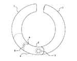
図中、14は一対の円弧状部材1,2の一方の開放端部に設けた突起、15はそれに対応して設けた窪みで、両者の間に耳たぶを挟み付けることにより、この発明のリング状耳飾りが耳たぶから抜け落ちるのをより確実に防止するよう機能する。
In the figure, 14 is a protrusion provided at one open end of the pair of
この発明の耳飾りは上述のように構成したので、リング状耳飾りであれば、上記一対の円弧状部材1,2の一方の開放端部にピアスのピンを突設したものであっても、また突設したものでなくともよい。
Since the earring of the present invention is configured as described above, if it is a ring-shaped earring, a pierced pin may protrude from one open end of the pair of
1,2 円弧状部材
3 軸受部
4 回転部
5 連結軸
6 係合部
7 凹部
8 硬質パッキング
9 すり割
10 連結ガイド
11 突起
12 凹溝
13 凹部
14 突起
15 窪み
DESCRIPTION OF
Claims (1)
Priority Applications (1)
| Application Number | Priority Date | Filing Date | Title |
|---|---|---|---|
| JP2004177985A JP4587280B2 (en) | 2004-06-16 | 2004-06-16 | Ring earrings |
Applications Claiming Priority (1)
| Application Number | Priority Date | Filing Date | Title |
|---|---|---|---|
| JP2004177985A JP4587280B2 (en) | 2004-06-16 | 2004-06-16 | Ring earrings |
Publications (3)
| Publication Number | Publication Date |
|---|---|
| JP2006000267A JP2006000267A (en) | 2006-01-05 |
| JP2006000267A5 JP2006000267A5 (en) | 2007-08-02 |
| JP4587280B2 true JP4587280B2 (en) | 2010-11-24 |
Family
ID=35769172
Family Applications (1)
| Application Number | Title | Priority Date | Filing Date |
|---|---|---|---|
| JP2004177985A Expired - Fee Related JP4587280B2 (en) | 2004-06-16 | 2004-06-16 | Ring earrings |
Country Status (1)
| Country | Link |
|---|---|
| JP (1) | JP4587280B2 (en) |
Families Citing this family (5)
| Publication number | Priority date | Publication date | Assignee | Title |
|---|---|---|---|---|
| KR101461299B1 (en) * | 2010-03-02 | 2014-11-13 | 다이니치 세이카 고교 가부시키가이샤 | Alkoxysilyl group-containing block copolymer, method for producing the same, resin-treated pigment, and pigment dispersion |
| JP2012034833A (en) * | 2010-08-06 | 2012-02-23 | Kosaikogei Co Ltd | Stopper of earring |
| JP2017209301A (en) * | 2016-05-25 | 2017-11-30 | 株式会社ワンダーワークス | Resin-made earrings |
| JP6675720B1 (en) * | 2019-04-24 | 2020-04-01 | 株式会社美創 | Jewelry |
| JP6688495B1 (en) * | 2019-06-28 | 2020-04-28 | 株式会社シンク | Trinkets |
Citations (2)
| Publication number | Priority date | Publication date | Assignee | Title |
|---|---|---|---|---|
| JPH09289910A (en) * | 1996-02-29 | 1997-11-11 | Jiyuerii Takuma:Kk | Structure for clip type earring |
| JP2000253914A (en) * | 1999-03-08 | 2000-09-19 | Kikushima:Kk | Earring |
-
2004
- 2004-06-16 JP JP2004177985A patent/JP4587280B2/en not_active Expired - Fee Related
Patent Citations (2)
| Publication number | Priority date | Publication date | Assignee | Title |
|---|---|---|---|---|
| JPH09289910A (en) * | 1996-02-29 | 1997-11-11 | Jiyuerii Takuma:Kk | Structure for clip type earring |
| JP2000253914A (en) * | 1999-03-08 | 2000-09-19 | Kikushima:Kk | Earring |
Also Published As
| Publication number | Publication date |
|---|---|
| JP2006000267A (en) | 2006-01-05 |
Similar Documents
| Publication | Publication Date | Title |
|---|---|---|
| JP4587280B2 (en) | Ring earrings | |
| JP3130993U (en) | Clip-on earrings | |
| JP2006000267A5 (en) | ||
| US20100186200A1 (en) | Slide fastener slider for easy mounting of a pull tab | |
| JP3139659U (en) | Clip-on earrings | |
| US6354106B1 (en) | Finger ring fitting aid | |
| JP3139659U7 (en) | ||
| JP3165289U (en) | Connecting ring | |
| JP5709116B1 (en) | Hinge structure | |
| KR200257415Y1 (en) | Buckle of belt | |
| JP2019198474A (en) | Holding structure of accessory | |
| JP6593946B1 (en) | Tightening structure for jewelry | |
| JP3107841U (en) | Clip-on earrings | |
| JP3222729U (en) | Clip-on earring | |
| JP2009247680A (en) | Earring and method of exchanging earring | |
| JP2011078460A (en) | Clip type earring | |
| JP3965454B2 (en) | Earrings | |
| JP6198359B1 (en) | Clip-on earrings | |
| US5025643A (en) | Holding clip | |
| JP2001061519A (en) | Earring | |
| JP3233807U (en) | Jewelry earrings | |
| JPH047774Y2 (en) | ||
| KR200235866Y1 (en) | Earring type earset | |
| KR200344804Y1 (en) | Tension locking goods for earring | |
| JP2000229007A (en) | Earring |
Legal Events
| Date | Code | Title | Description |
|---|---|---|---|
| A521 | Written amendment |
Free format text: JAPANESE INTERMEDIATE CODE: A523 Effective date: 20070618 |
|
| A621 | Written request for application examination |
Free format text: JAPANESE INTERMEDIATE CODE: A621 Effective date: 20070618 |
|
| A977 | Report on retrieval |
Free format text: JAPANESE INTERMEDIATE CODE: A971007 Effective date: 20090414 |
|
| A131 | Notification of reasons for refusal |
Free format text: JAPANESE INTERMEDIATE CODE: A131 Effective date: 20100614 |
|
| A521 | Written amendment |
Free format text: JAPANESE INTERMEDIATE CODE: A523 Effective date: 20100808 |
|
| TRDD | Decision of grant or rejection written | ||
| A01 | Written decision to grant a patent or to grant a registration (utility model) |
Free format text: JAPANESE INTERMEDIATE CODE: A01 Effective date: 20100825 |
|
| A01 | Written decision to grant a patent or to grant a registration (utility model) |
Free format text: JAPANESE INTERMEDIATE CODE: A01 |
|
| A61 | First payment of annual fees (during grant procedure) |
Free format text: JAPANESE INTERMEDIATE CODE: A61 Effective date: 20100902 |
|
| R150 | Certificate of patent or registration of utility model |
Free format text: JAPANESE INTERMEDIATE CODE: R150 |
|
| FPAY | Renewal fee payment (event date is renewal date of database) |
Free format text: PAYMENT UNTIL: 20130917 Year of fee payment: 3 |
|
| LAPS | Cancellation because of no payment of annual fees |