JP4587186B2 - Impulse image display device and driving method thereof. - Google Patents
Impulse image display device and driving method thereof. Download PDFInfo
- Publication number
- JP4587186B2 JP4587186B2 JP2008111518A JP2008111518A JP4587186B2 JP 4587186 B2 JP4587186 B2 JP 4587186B2 JP 2008111518 A JP2008111518 A JP 2008111518A JP 2008111518 A JP2008111518 A JP 2008111518A JP 4587186 B2 JP4587186 B2 JP 4587186B2
- Authority
- JP
- Japan
- Prior art keywords
- image
- gradation
- gradation conversion
- image signal
- frame frequency
- Prior art date
- Legal status (The legal status is an assumption and is not a legal conclusion. Google has not performed a legal analysis and makes no representation as to the accuracy of the status listed.)
- Expired - Fee Related
Links
Images


Classifications
-
- G—PHYSICS
- G09—EDUCATION; CRYPTOGRAPHY; DISPLAY; ADVERTISING; SEALS
- G09G—ARRANGEMENTS OR CIRCUITS FOR CONTROL OF INDICATING DEVICES USING STATIC MEANS TO PRESENT VARIABLE INFORMATION
- G09G3/00—Control arrangements or circuits, of interest only in connection with visual indicators other than cathode-ray tubes
- G09G3/20—Control arrangements or circuits, of interest only in connection with visual indicators other than cathode-ray tubes for presentation of an assembly of a number of characters, e.g. a page, by composing the assembly by combination of individual elements arranged in a matrix no fixed position being assigned to or needed to be assigned to the individual characters or partial characters
- G09G3/22—Control arrangements or circuits, of interest only in connection with visual indicators other than cathode-ray tubes for presentation of an assembly of a number of characters, e.g. a page, by composing the assembly by combination of individual elements arranged in a matrix no fixed position being assigned to or needed to be assigned to the individual characters or partial characters using controlled light sources
-
- G—PHYSICS
- G09—EDUCATION; CRYPTOGRAPHY; DISPLAY; ADVERTISING; SEALS
- G09G—ARRANGEMENTS OR CIRCUITS FOR CONTROL OF INDICATING DEVICES USING STATIC MEANS TO PRESENT VARIABLE INFORMATION
- G09G2320/00—Control of display operating conditions
- G09G2320/02—Improving the quality of display appearance
- G09G2320/0247—Flicker reduction other than flicker reduction circuits used for single beam cathode-ray tubes
-
- G—PHYSICS
- G09—EDUCATION; CRYPTOGRAPHY; DISPLAY; ADVERTISING; SEALS
- G09G—ARRANGEMENTS OR CIRCUITS FOR CONTROL OF INDICATING DEVICES USING STATIC MEANS TO PRESENT VARIABLE INFORMATION
- G09G2320/00—Control of display operating conditions
- G09G2320/02—Improving the quality of display appearance
- G09G2320/0271—Adjustment of the gradation levels within the range of the gradation scale, e.g. by redistribution or clipping
- G09G2320/0276—Adjustment of the gradation levels within the range of the gradation scale, e.g. by redistribution or clipping for the purpose of adaptation to the characteristics of a display device, i.e. gamma correction
-
- G—PHYSICS
- G09—EDUCATION; CRYPTOGRAPHY; DISPLAY; ADVERTISING; SEALS
- G09G—ARRANGEMENTS OR CIRCUITS FOR CONTROL OF INDICATING DEVICES USING STATIC MEANS TO PRESENT VARIABLE INFORMATION
- G09G2340/00—Aspects of display data processing
- G09G2340/04—Changes in size, position or resolution of an image
- G09G2340/0407—Resolution change, inclusive of the use of different resolutions for different screen areas
- G09G2340/0435—Change or adaptation of the frame rate of the video stream
Landscapes
- Engineering & Computer Science (AREA)
- Physics & Mathematics (AREA)
- Computer Hardware Design (AREA)
- General Physics & Mathematics (AREA)
- Theoretical Computer Science (AREA)
- Control Of Indicators Other Than Cathode Ray Tubes (AREA)
- Transforming Electric Information Into Light Information (AREA)
- Controls And Circuits For Display Device (AREA)
- Liquid Crystal Display Device Control (AREA)
Description
本発明は、画像表示装置及びその駆動方法に関する。特に、CRTやFED等のインパルス型の画像表示装置及びその駆動方法に関する。 The present invention relates to an image display device and a driving method thereof. In particular, the present invention relates to an impulse-type image display device such as a CRT or FED and a driving method thereof.
画像表示装置を動画表示の観点から分類した場合、ホールド型画像表示装置とインパルス型画像表示装置に分類することができる。 When image display devices are classified from the viewpoint of moving image display, they can be classified into hold type image display devices and impulse type image display devices.
ホールド型画像表示装置は、1フレーム期間に同じ画像を表示し続けるものである。ホールド型画像表示装置としては、TFTを用いた液晶表示装置や有機ELディスプレイ等が知られている。 The hold-type image display device continues to display the same image in one frame period. As the hold-type image display device, a liquid crystal display device using a TFT, an organic EL display, and the like are known.
これに対し、インパルス型画像表示装置は、1フレーム期間のうち走査された期間だけ画素に画像が表示され、走査直後から画素の輝度が低下するものである。インパルス型画像表示装置としては、CRTやFED等が知られている。 In contrast, in the impulse-type image display device, an image is displayed on a pixel only during a scanned period of one frame period, and the luminance of the pixel decreases immediately after scanning. Known impulse-type image display devices include CRT and FED.
インパルス型画像表示装置は、ホールド型画像表示装置に比べて動画視認性がよいという利点を有する。しかしながら、インパルス型画像表示装置は、フリッカーというちらつき感の問題が生じることがある。 The impulse type image display device has an advantage that the moving image visibility is better than the hold type image display device. However, the impulse-type image display apparatus may have a flickering problem called flicker.
周波数が低い方形波の光刺激を観察するとフリッカーが知覚される。この周波数を徐々に上げていくとフリッカーが知覚されなくなる。フリッカーがちょうど知覚されなくなる周波数は、臨界融合周波数(CFF:Critical Fusion Frequency)と呼ばれている。CFFよりも高い周波数の光刺激は、輝度を時間平均した強さの光として知覚されることが知られている(Talbot−Plateau則)。また、CFFは視標の平均輝度の対数に比例することが知られている(Ferry−Porter則)。更に、CFFは視標の面積の対数に比例することが知られている(Granit−Harper則)。これらのことから、フレーム周波数が低い場合、輝度が高い場合、表示面積が広い場合にはフリッカーが知覚されやすくなるといえる。 Flicker is perceived when light stimulation of a square wave having a low frequency is observed. When this frequency is gradually increased, flicker is not perceived. The frequency at which the flicker is just not perceived is called the critical fusion frequency (CFF). It is known that a light stimulus having a frequency higher than that of CFF is perceived as light having intensity obtained by averaging the luminance over time (Talbot-Plateau rule). Further, it is known that CFF is proportional to the logarithm of the average luminance of the target (Ferry-Porter rule). Furthermore, it is known that CFF is proportional to the logarithm of the target area (Granit-Harper rule). From these facts, it can be said that flicker is easily perceived when the frame frequency is low, the luminance is high, or the display area is large.
フリッカーの妨害感を十分なレベルまで低下させるフレーム周波数として、50Hz〜60Hzが実用的には用いられている。しかし、近年の大画面高輝度ディスプレイにおいては、これらの周波数ではフリッカーが知覚される可能性もある。 Practically 50 Hz to 60 Hz is used as a frame frequency for reducing flicker interference to a sufficient level. However, in recent large-screen high-intensity displays, flicker may be perceived at these frequencies.
そこで、フリッカーが知覚されにくくするために、例えば60Hzの映像フレームを単純に2回表示して120Hzの映像として表示する技術が知られている。 Therefore, in order to make it difficult to perceive flicker, for example, a technique of simply displaying a 60 Hz video frame twice and displaying it as a 120 Hz video is known.
また、フレーム周波数を倍にするとともに、画像の高周波成分を取り除く処理を行う技術が知られている(特許文献1参照)。
インパルス型画像表示装置のフリッカーを知覚されにくくするためにフレーム周波数を高くすると、インパルス型画像表示装置のメリットである画像の輝き感や生き生き感、存在感や質感、立体感などが減少することがわかった。 Increasing the frame frequency in order to make the flicker of the impulse-type image display device difficult to perceive may reduce the shine, vividness, presence, texture, and stereoscopic effect of the image, which are the merits of the impulse-type image display device. all right.
本発明は、フリッカーが知覚されにくく、かつ、画像の輝き感などの低減を抑制する画像表示装置及びその駆動方法を提供することを目的とする。 SUMMARY OF THE INVENTION An object of the present invention is to provide an image display apparatus and a driving method thereof in which flicker is hardly perceived and the reduction in the brightness of an image is suppressed.
本発明のインパルス型画像表示装置は、線順次走査により1フレームの画像を形成し、該1フレーム期間のうち画素が走査された期間だけ、該画素に画像が表示され、走査直後から該画素の輝度が低下するインパルス型画像表示装置であって、第1フレーム周波数の画像信号を該第1フレーム周波数よりも高い第2フレーム周波数の画像信号に変換するフレーム周波数変換回路と、前記第2フレーム周波数の画像信号の階調を、ゼロより大きく1より小さい第1の階調変換比率で変換する第1の階調変換回路と、前記第2フレーム周波数の画像信号の階調を、ゼロより大きく前記第1の階調変換比率より小さい第2の階調変換比率で変換する第2の階調変換回路と、前記第1の階調変換回路の出力画像信号と前記第2の階調変換回路の出力画像信号とをそれぞれ周期的に選択する選択回路とを有することを特徴とする。 The impulse-type image display device of the present invention forms an image of one frame by line sequential scanning, and an image is displayed on the pixel only during the period during which the pixel is scanned in the one frame period. An impulse-type image display device with reduced luminance, wherein a frame frequency conversion circuit converts an image signal having a first frame frequency into an image signal having a second frame frequency higher than the first frame frequency, and the second frame frequency. A first gradation conversion circuit that converts the gradation of the image signal at a first gradation conversion ratio that is greater than zero and less than 1, and the gradation of the image signal at the second frame frequency is greater than zero and the gradation is greater than zero. A second gradation conversion circuit for converting at a second gradation conversion ratio smaller than the first gradation conversion ratio, an output image signal of the first gradation conversion circuit, and the second gradation conversion circuit. Output image And having a selection circuit for selecting a signal, respectively cyclically.
また、本発明のインパルス型画像表示装置は、フレーム周波数が75Hz以上である画像信号の階調を変換する複数の階調変換回路と、前記複数の階調変換回路の出力画像を周期的に選択する選択回路と、を有し、前記複数の階調変換回路のうち少なくとも1つの階調変換回路の階調変換比率と他の階調変換回路の階調変換比率とは異なることを特徴とする。 In addition, the impulse-type image display device of the present invention periodically selects a plurality of gradation conversion circuits that convert gradations of an image signal having a frame frequency of 75 Hz or more, and an output image of the plurality of gradation conversion circuits. A gradation conversion ratio of at least one gradation conversion circuit of the plurality of gradation conversion circuits is different from a gradation conversion ratio of another gradation conversion circuit. .
また、本発明のインパルス型画像表示装置の駆動方法は、線順次走査により1フレームの画像を形成し、該1フレーム期間のうち画素が走査された期間だけ、該画素に画像が表示され、走査直後から該画素の輝度が低下するインパルス型画像表示装置の駆動方法であって、第1フレーム周波数の画像信号を該第1フレーム周波数よりも高い第2フレーム周波数の画像信号に変換するステップと、前記第2フレーム周波数の画像信号の階調を、ゼロより大きく1より小さい第1の階調変換比率で変換するステップと、前記第2フレーム周波数の画像信号の階調を、ゼロより大きく前記第1の階調変換比率より小さい第2の階調変換比率で変換するステップと、前記第1の階調変換比率で変換された画像信号と前記第2の階調変換比率で変換された画像信号とをそれぞれ周期的に選択するステップとを有することを特徴とする。 Further, according to the driving method of the impulse-type image display device of the present invention, an image of one frame is formed by line-sequential scanning, and an image is displayed on the pixel only during the period in which the pixel is scanned in the one frame period. Impulse-type image display device driving method in which the luminance of the pixel is reduced immediately after, converting an image signal having a first frame frequency into an image signal having a second frame frequency higher than the first frame frequency; Converting the gradation of the image signal of the second frame frequency at a first gradation conversion ratio larger than zero and smaller than 1, and converting the gradation of the image signal of the second frame frequency larger than zero to the first Converting at a second gradation conversion ratio smaller than one gradation conversion ratio, an image signal converted at the first gradation conversion ratio, and being converted at the second gradation conversion ratio. Characterized by a step of selecting the image signal, respectively cyclically.
また、本発明のインパルス型画像表示装置の駆動方法は、フレーム周波数が75Hz以上である画像信号の階調を異なる階調変換比率で周期的に変換する階調変換工程を有することを特徴とする。 Also, the driving method of the impulse type image display device of the present invention includes a gradation conversion step of periodically converting gradations of an image signal having a frame frequency of 75 Hz or more at different gradation conversion ratios. .
なお、本発明において「フレーム周波数」とは、プログレッシブ走査を行う場合に1秒あたりに表示される画像(フレーム)の数を意味し、インターレース走査を行う場合は1秒あたりに表示される画像(フィールド)の数を意味する。 In the present invention, the “frame frequency” means the number of images (frames) displayed per second when progressive scanning is performed, and the images displayed per second (when interlace scanning is performed). Field).
本発明によれば、フリッカーが知覚されにくく、かつ、画像の輝き感などの低減を抑制することができる。 According to the present invention, it is difficult to perceive flicker and it is possible to suppress a reduction in the brightness of an image.
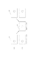
点滅刺激の見え方に関して、見かけ上はちらつきを感じないが、見かけの明るさ知覚に影響を及ぼす点滅周波数が存在することが知られている。図1(a)のような刺激条件で別の光刺激を加え、輝度弁別閾値を定常光と点滅光で測定した結果が図1(b)である。低い点滅周波数では点滅光の方が定常光より明るく見えるため、閾値の光量は少なくなる。しかし、CFF近傍では点滅光の方が不安定に見えて閾値は上昇する。更に点滅周波数を高くすると、定常光での閾値とほぼ等しくなる。このように、定常光での表示状態と同じように見える点滅周波数はSFF(Stable Fusion Frequency)と呼ばれている。ここで、SFFの方がCFFよりも高いことが知られている。 It is known that there is a blinking frequency that affects the perception of the apparent brightness, although the flickering appearance does not feel flickering. FIG. 1B shows a result obtained by applying another light stimulus under the stimulus condition as shown in FIG. 1A and measuring the luminance discrimination threshold with the steady light and the flashing light. Since the flashing light appears brighter than the steady light at a low flashing frequency, the threshold light quantity is reduced. However, in the vicinity of the CFF, the blinking light appears to be unstable and the threshold value increases. If the blinking frequency is further increased, it becomes substantially equal to the threshold for steady light. In this way, the blinking frequency that looks the same as the display state with steady light is called SFF (Stable Fusion Frequency). Here, it is known that SFF is higher than CFF.
このようにCFFとSFFとが異なることは、この2つが異なる生体反応に起因するものであることを示している。この点について、視覚系を簡単に説明した図2を用いて説明する。 Thus, the difference between CFF and SFF indicates that the two are caused by different biological reactions. This point will be described with reference to FIG. 2 which briefly explains the visual system.
まず、網膜から第1次視覚中枢に信号を伝達する視神経においては、粗密波にて信号を伝達している。そして、第1次視覚中枢においては、あるインターバル期間中に到達した信号を積分して、画像処理を行なうことがわかっている。粗密波のパルス間隔および視覚中枢での画像処理インターバルは、両方とも周波数に関係した定数であり、その定数により信号を伝達する周波数の上限が決まる。粗密波の周波数の方が視覚中枢での画像処理インターバルの周波数よりも高い。これより、視神経内の粗密波のパルス間隔がSFFを決めるものであり、視覚中枢での画像処理インターバルがCFFを決めるものであると考えられている。 First, in the optic nerve that transmits a signal from the retina to the primary visual center, the signal is transmitted by a dense wave. In the primary visual center, it is known that image processing is performed by integrating signals that arrive during a certain interval. The pulse interval of the dense wave and the image processing interval in the visual center are both constants related to the frequency, and the upper limit of the frequency at which the signal is transmitted is determined by the constants. The frequency of the dense wave is higher than the frequency of the image processing interval in the visual center. From this, it is considered that the pulse interval of the dense wave in the optic nerve determines SFF, and the image processing interval in the visual center determines CFF.
次に、視神経内の粗密波とSFFとの関係について説明する。図3は、視神経内の粗密波を模式的に示す図である。50Hzの光信号の伝達パルスと比べて、70Hzの光信号の伝達パルスの方が粗密波が均等になっていることが分かる。このように、光信号の周波数が高くなると粗密波が次第に均等になり、SFFに相当する周波数において粗密波がほとんど均等になると考えられる。 Next, the relationship between the dense waves in the optic nerve and SFF will be described. FIG. 3 is a diagram schematically showing a rough wave in the optic nerve. It can be seen that the dense wave is more uniform in the transmission pulse of the optical signal of 70 Hz than in the transmission pulse of the optical signal of 50 Hz. As described above, it is considered that when the frequency of the optical signal is increased, the rough waves gradually become uniform, and the rough waves are almost uniform at the frequency corresponding to the SFF.
次に、第1次視覚中枢における粗密波のパルス数と画像処理インターバルの相互作用について、図4を用いて説明する。 Next, the interaction between the number of pulses of dense waves and the image processing interval in the primary visual center will be described with reference to FIG.
上述したように、粗密波のパルス数は、光信号の周波数によって変わる。本図においては、画像処理インターバルが約20Hzの場合を示した。 As described above, the number of pulses of the dense wave varies depending on the frequency of the optical signal. In this figure, the case where the image processing interval is about 20 Hz is shown.
図に示した例の場合、画像処理インターバルあたりの伝達パルス数は、50Hzの光信号の場合、35本、33本、32本のように異なっている。これに対し、70Hzの光信号の場合、39本、39本、39本となり、画像処理インターバルあたりの伝達パルス数が等しくなっている。このように50Hzの場合は、画像処理インターバルあたりの伝達パルス数にうなりのような数値のぶれが生じるが、70Hzの場合はこのような数値のぶれは生じない。 In the case of the example shown in the figure, the number of transmission pulses per image processing interval is different, such as 35, 33, and 32 in the case of a 50 Hz optical signal. In contrast, in the case of a 70 Hz optical signal, the number is 39, 39, and 39, and the number of transmitted pulses per image processing interval is equal. As described above, in the case of 50 Hz, a numerical fluctuation like a beat occurs in the number of transmission pulses per image processing interval, but in the case of 70 Hz, such a numerical fluctuation does not occur.
画像処理インターバルには個人差があり、光信号の周波数を60Hzにすると、インターバルの短い人はうなりを感じるが、インターバルの長い人はうなりを感じない。また、画像処理インターバルは輝度によっても異なる。輝度が高い場合はインターバルが短くなり、輝度が低い場合はインターバルが長くなることが知られている。そこで、光信号の周波数を60Hzにし、輝度が高くなりインターバルが短くなるとうなりを感じ、輝度が低くなりインターバルが長くなるとうなりを感じなくなる。このことは、フリッカーを感じる周波数であるCFFが輝度によって異なるという実験結果とも一致する。 There are individual differences in the image processing interval. When the frequency of the optical signal is set to 60 Hz, a person with a short interval feels a beat, but a person with a long interval does not feel a beat. Also, the image processing interval varies depending on the luminance. It is known that when the luminance is high, the interval is short, and when the luminance is low, the interval is long. Therefore, when the frequency of the optical signal is set to 60 Hz and the brightness is increased and the interval is shortened, a beat is felt, and when the brightness is decreased and the interval is lengthened, the beat is not felt. This coincides with the experimental result that CFF, which is the frequency at which flicker is felt, varies depending on the luminance.
以上より、CFFとSFFとの間の周波数においては、周波数がCFF以上であるためうなりを感じることはない。しかし、周波数がSFF以下であるため、光刺激は視神経を通過して第1次視覚中枢に到達し、その光刺激の変動は、第1次視覚中枢内の画像処理に影響を与え得る。そして、この第1次視覚中枢内の画像処理への影響が、生き生き感や立体感、輝き感などに影響していると考えられる。 From the above, at the frequency between the CFF and the SFF, since the frequency is equal to or higher than the CFF, no beat is felt. However, because the frequency is less than or equal to SFF, the light stimulus passes through the optic nerve to reach the primary visual center, and variations in the light stimulus can affect image processing within the primary visual center. And it is thought that the influence on the image processing in the primary visual center influences a lively feeling, a three-dimensional feeling, a feeling of brightness, and the like.
ここで、フリッカーが知覚されにくく、かつ、画像の輝き感などの低減を抑制するために、例えば、60Hzの画像をCFFとSFFとの間のフレーム周波数(例えば、72Hz)に変換する構成を採用することも考えられる。しかし、これを実現しようとすると、フレーム補間画像の生成の負荷が増大したり、連続するフレームにおけるフレーム補間画像の比率が増大し画質が悪化するという問題が生じる。 Here, for example, a configuration in which an image of 60 Hz is converted into a frame frequency (for example, 72 Hz) between CFF and SFF is employed in order to suppress flicker and to prevent reduction in the brightness of the image. It is also possible to do. However, if this is to be realized, there arises a problem that the load of generating a frame interpolation image increases, or the ratio of the frame interpolation image in consecutive frames increases to deteriorate the image quality.
本発明は、上述したような生体における影響が輝き感の原因であることに着目し、画像のフレーム周波数をCFFとSFFとの間の周波数に直接変換する以外の手段により、CFFとSFFとの間のフレーム周波数と同様の画像表示を行うものである。より詳細には、フレーム周波数を少しずらしてCFFとSFFとの間の周波数にするのではなく、フレーム周波数をN倍や1.5倍などの作りやすい周波数に変換した後に、フレームの明暗比を調整する。これにより、N倍や1.5倍などの周波数からCFFとSFFとの間の周波数に周波数を下げることと同じ影響を視覚効果として与えるものである。 The present invention pays attention to the fact that the influence on the living body as described above is the cause of the shine, and the CFF and the SFF are converted by means other than directly converting the frame frequency of the image into a frequency between the CFF and the SFF. The same image display as the frame frequency is performed. More specifically, rather than shifting the frame frequency slightly to a frequency between CFF and SFF, the frame frequency is converted to a frequency that is easy to make, such as N times or 1.5 times, and then the contrast ratio of the frame is changed. adjust. This gives the same effect as a visual effect when the frequency is lowered from a frequency such as N times or 1.5 times to a frequency between CFF and SFF.
以下、本発明の画像表示装置の具体的な構成について説明する。 Hereinafter, a specific configuration of the image display device of the present invention will be described.
<第1の実施形態>
図5は、本発明の第1の実施形態における周波数と階調変換比率の関係を示す模式図である。横軸は時間を示し、縦軸は輝度を示す。
<First Embodiment>
FIG. 5 is a schematic diagram showing the relationship between the frequency and the gradation conversion ratio in the first embodiment of the present invention. The horizontal axis indicates time, and the vertical axis indicates luminance.
図5(a)は、60Hzのフレーム周波数の画像をそのままインパルス駆動したものである。図5(b)は、補間フレーム画像を作成し、元画像の倍のフレーム周波数(120Hz)でインパルス駆動したものである。図5(c)は、更に階調変換を施してオリジナルフレーム画像と補間フレーム画像の輝度を異なるものとしてインパルス駆動したものである。 FIG. 5A shows an impulse drive of an image having a frame frequency of 60 Hz. FIG. 5B shows an interpolated frame image that is impulse-driven at a frame frequency (120 Hz) that is twice that of the original image. FIG. 5 (c) shows an example in which tone conversion is further performed and impulse driving is performed with the luminance of the original frame image and the interpolation frame image being different.
本実施形態では、フレーム周波数を2倍とする例を用いて説明するが、本発明はこれに限られるものではない。整数倍や1より大きい半整数倍のフレーム周波数は特に周波数の変換を行いやすい。 In the present embodiment, an example in which the frame frequency is doubled will be described, but the present invention is not limited to this. Frame frequencies that are integer multiples or half integer multiples greater than 1 are particularly easy to convert.
本実施形態では、元画像のフレーム周波数がCFF以下であり、周波数変換した後のフレーム周波数がSFF以上となるように周波数変換を行う。上述した通り、CFFとSFFは人や輝度によって異なるが、本実施形態では、CFF=65Hz、SFF=75Hzと仮定してフレーム周波数の変換を行った。 In the present embodiment, the frequency conversion is performed so that the frame frequency of the original image is CFF or less and the frame frequency after frequency conversion is SFF or more. As described above, CFF and SFF differ depending on the person and luminance, but in this embodiment, the frame frequency is converted on the assumption that CFF = 65 Hz and SFF = 75 Hz.
次に、階調変換処理を行い、図5(c)に示すように、オリジナルフレーム画像と補間フレーム画像の輝度が周期的に変わるようインパルス駆動されるようにした。 Next, gradation conversion processing is performed, and as shown in FIG. 5C, impulse driving is performed so that the luminance of the original frame image and the interpolated frame image changes periodically.
図6は、本実施形態により表示される表示画像を示す模式図である。 FIG. 6 is a schematic diagram showing a display image displayed according to the present embodiment.
元画像81から、元画像の半分の輝度のオリジナルフレーム画像82と補間フレーム画像83を生成する。そして、オリジナルフレーム画像82と補間フレーム画像83のそれぞれについて、階調変換によって輝度を変更し、明るいメインフレーム画像(M1)84と暗いサブフレーム画像(S1)85を生成する。
From the
メインフレーム画像の階調数とサブフレーム画像の階調数を足し合わせて、元画像と同一の階調数にする場合、メインフレーム画像の階調数は元画像の階調数の半分以上となり、サブフレーム画像の階調数は元画像の階調数の半分以下となる。 When adding the number of gradations of the main frame image and the number of gradations of the subframe image to the same number of gradations as the original image, the number of gradations of the main frame image is more than half of the number of gradations of the original image. The number of gradations of the sub-frame image is less than half of the number of gradations of the original image.
なお、階調変換を行った後の画像の輝度は、必ずしも元画像の輝度と同一にする必要はない。すなわち、変換階調変換を行った後の画像を元画像より明るくしたり暗くしたりしてもよい。また、ガンマ特性を変えたりしても良い。 Note that the luminance of the image after gradation conversion is not necessarily the same as the luminance of the original image. That is, the image after the conversion gradation conversion may be made brighter or darker than the original image. Further, the gamma characteristic may be changed.
次に、本実施形態の駆動を行うための回路構成について、図7を用いて説明する。 Next, a circuit configuration for driving the present embodiment will be described with reference to FIG.
図中、91はフレーム周波数変換回路、92は逆ガンマ変換回路である。画像の階調を逆ガンマ変換することで、ガンマ系画像からリニア系画像に変換し、階調の演算処理を行いやすくなる。93、94は階調変換回路である。特に、93はメインフレーム用階調変換回路(本発明の「第1の階調変換回路」に相当)、94はサブフレーム用階調変換回路(本発明の「第2の階調変換回路」に相当)である。95はメインフレーム用階調変換回路93の出力画像とサブフレーム用階調変換回路94の出力画像とを切り替えるセレクタ(本発明の「選択回路」に相当)である。本実施形態では、セレクタ95は、メインフレーム用階調変換回路93の出力とサブフレーム用階調変換回路94の出力とを交互に選択する。96は階調変換回路93、94に対しゲインまたはゲインテーブルを設定するコントローラである。97はガンマ変換回路である。ガンマ変換回路97からの出力がインパルス型表示パネル98に入力される。これらの構成により本実施形態のインパルス型画像表示装置90が構成されている。
In the figure, 91 is a frame frequency conversion circuit, and 92 is an inverse gamma conversion circuit. By performing inverse gamma conversion on the gradation of the image, it is possible to convert the gamma image into a linear image, and to easily perform gradation calculation processing.
ここで、フレーム周波数変換回路91について、より詳しく説明する。 Here, the frame frequency conversion circuit 91 will be described in more detail.
フレーム周波数変換回路91には、チューナーなどの映像入力装置からの元画像が入力される。本実施形態では、この元画像のフレーム周波数を60Hzとする。この元画像のフレーム周波数は、本発明の第1フレーム周波数に相当する。続いて、フレーム周波数変換回路91は、元画像よりも高い周波数の画像に変換する。本実施形態では、120Hzに変換する。変換後のフレーム周波数は、本発明の第2フレーム周波数に相当する。これによって、変換後のフレーム周波数がSFF以上(75Hz以上)の周波数となる。図6で説明したように、周波数変換後のフレームであるオリジナルフレーム画像82と補間フレーム画像83をそれぞれ元画像の半分の輝度としてもよい。しかし、このように同じ画像を2度表示すると動画ブレと呼ばれる2重線状の妨害が発生することがある。そのため、図8に示すように、元画像のフレーム画像101とその次のフレーム画像102から、動きベクトル検知などを行い、補間フレーム画像103を形成する構成を採用することもできる。補間フレーム画像103の作成方法としては、動きベクトル検知などの公知の技術を採用することができる。
An original image from a video input device such as a tuner is input to the frame frequency conversion circuit 91. In this embodiment, the frame frequency of the original image is 60 Hz. The frame frequency of the original image corresponds to the first frame frequency of the present invention. Subsequently, the frame frequency conversion circuit 91 converts the image into a higher frequency image than the original image. In this embodiment, it converts to 120 Hz. The converted frame frequency corresponds to the second frame frequency of the present invention. Thereby, the frame frequency after conversion becomes a frequency of SFF or higher (75 Hz or higher). As described with reference to FIG. 6, the original frame image 82 and the interpolated frame image 83, which are frames after frequency conversion, may each have half the luminance of the original image. However, if the same image is displayed twice in this way, a double line-like disturbance called moving image blur may occur. Therefore, as shown in FIG. 8, it is also possible to adopt a configuration in which a motion vector is detected from the frame image 101 of the original image and the
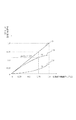
図9は、本実施形態の階調変換回路93、94が行う階調変換を示す図である。横軸は階調変換処理前の階調を示し、縦軸は階調変換処理後の階調を示す。階調1.0は最大階調を、階調0は最小階調を示す。階調変換処理前の階調に対する階調変換処理後の階調の比率を、階調変換比率とする。
FIG. 9 is a diagram showing the gradation conversion performed by the
図中、111はメインフレーム画像(M1)への階調変換比率(本発明の「第1の階調変換比率」に相当)を決める直線グラフである。112はサブフレーム画像(S1)への階調変換比率(本発明の「第2の階調変換比率」に相当)を決める直線グラフである。113はメインフレーム画像(M1)とサブフレーム画像(S1)の合計を示すグラフである。図から明らかなように、本実施形態では、メインフレーム画像の階調変換比率に対するサブフレーム画像の階調変換比率が、階調によらずに一定となっている。
In the figure, 111 is a straight line graph that determines the gradation conversion ratio (corresponding to the “first gradation conversion ratio” of the present invention) to the main frame image (M1).
メインフレーム画像(M1)とサブフレーム画像(S1)の合計を示すグラフ113が、45度の直線になるように階調変換111と112を決めると、元画像の輝度と階調変換後の輝度を等しくすることができる。元画像の輝度と階調変換後の輝度を等しくする必要がない場合は、メインフレーム画像(M1)とサブフレーム画像(S1)の合計を示すグラフ113が45度の直線となる必要はない。
When the
本実施形態では、メインフレーム画像(M1)の階調変換比率を3分の2、サブフレーム画像(S1)の階調変換比率を3分の1とした。 In the present embodiment, the gradation conversion ratio of the main frame image (M1) is set to 2/3, and the gradation conversion ratio of the subframe image (S1) is set to 1/3.
メインフレーム画像(M1)とサブフレーム画像(S1)の階調変換比率は、以下のような条件を満たす必要がある。 The gradation conversion ratio between the main frame image (M1) and the subframe image (S1) needs to satisfy the following conditions.
1つ目の条件として、メインフレーム画像とサブフレーム画像を交互に表示した時に、フリッカーが激しく知覚されるほど、メインフレーム画像とサブフレーム画像の輝度比を大きくしないようにする必要がある。そのため、メインフレーム画像の輝度はサブフレーム画像の輝度の4倍を超えないようにする必要がある。 As a first condition, when the main frame image and the sub frame image are alternately displayed, it is necessary to prevent the luminance ratio between the main frame image and the sub frame image from being increased so that flicker is perceived violently. Therefore, it is necessary that the luminance of the main frame image does not exceed four times the luminance of the sub frame image.
2つ目の条件として、メインフレーム画像とサブフレーム画像を交互に表示した時に、輝き感などがなくなるほど輝度比を小さくしないようにする必要がある。そのため、メインフレーム画像の輝度はサブフレーム画像の輝度の1.5倍以上である必要がある。 As a second condition, it is necessary to prevent the luminance ratio from becoming so small that the radiance is lost when the main frame image and the sub frame image are alternately displayed. Therefore, the luminance of the main frame image needs to be 1.5 times or more that of the sub frame image.
メインフレーム画像の輝度がサブフレーム画像の輝度の4倍となるのは、メインフレーム画像とサブフレーム画像の輝度比が4:1となるときである。また、メインフレーム画像の輝度がサブフレーム画像の輝度の1.5倍となるのは、メインフレーム画像とサブフレーム画像の輝度比が3:2となるときである。これは、メインフレーム画像の輝度に対するサブフレーム画像の輝度が25%以上67%以下となる条件ということもできる。 The luminance of the main frame image is four times the luminance of the sub frame image when the luminance ratio between the main frame image and the sub frame image is 4: 1. Further, the luminance of the main frame image is 1.5 times the luminance of the sub frame image when the luminance ratio of the main frame image and the sub frame image is 3: 2. This can also be said to be a condition that the luminance of the sub-frame image is 25% or more and 67% or less with respect to the luminance of the main frame image.
上述したような階調変換を行った画像をインパルス型画像表示装置に表示してみたところ、120Hzで表示している画像にも関わらず、60Hzで表示した場合のように、輝き感や生き生き感、質感や立体感などを感じられることが確認できた。 When an image subjected to gradation conversion as described above is displayed on an impulse-type image display device, the image is displayed at 60 Hz in spite of the image displayed at 120 Hz. It was confirmed that you can feel the texture and three-dimensionality.
<第2の実施形態>
本実施形態は、階調変換回路93、94の特性が第1の実施形態と異なる。それ以外の点については、第1の実施形態と同様である。
<Second Embodiment>
In the present embodiment, the characteristics of the
図10は、本実施形態の階調変換回路93、94が行う階調変換を示す図である。
FIG. 10 is a diagram showing the gradation conversion performed by the
図中、121はメインフレーム画像(M1)への階調変換比率を示す曲線グラフ、122はサブフレーム画像(S1)への階調変換比率を示す曲線グラフ、123はメインフレーム画像とサブフレーム画像の合計を示す直線グラフである。 In the figure, 121 is a curve graph showing the gradation conversion ratio to the main frame image (M1), 122 is a curve graph showing the gradation conversion ratio to the subframe image (S1), and 123 is the main frame image and the subframe image. It is a straight line graph which shows the sum total.
メインフレーム画像(M1)とサブフレーム画像(S1)の合計を示すグラフ123が、45度の直線になるように階調変換121と122を決めると、元画像の輝度と階調変換後の輝度を等しくすることができる。元画像の輝度と階調変換後の輝度を等しくする必要がない場合は、メインフレーム画像(M1)とサブフレーム画像(S1)の合計を示すグラフ123が45度の直線となる必要はない。
When the
本実施形態では、低階調領域ではメインフレーム画像(M1)の階調変換比率に対するサブフレーム画像(S1)の階調変換比率の割合が小さい。一方、高階調領域ではメインフレーム画像(M1)の階調変換比率に対するサブフレーム画像(S1)の階調変換比率の割合が大きくなる。 In the present embodiment, the ratio of the gradation conversion ratio of the sub-frame image (S1) to the gradation conversion ratio of the main frame image (M1) is small in the low gradation area. On the other hand, in the high gradation region, the ratio of the gradation conversion ratio of the sub-frame image (S1) to the gradation conversion ratio of the main frame image (M1) increases.
階調変換比率を本実施形態のような特性にすることによって、フリッカーが知覚されにくい低階調領域では、メインフレーム画像のみの表示に近くなり、画質がよくなる。また、フリッカーが知覚されやすい高階調領域では、メインフレーム画像とサブフレーム画像の輝度が近づき、フリッカーを知覚されにくくすることができる。 By setting the gradation conversion ratio to the characteristics as in this embodiment, in a low gradation area where flicker is hardly perceived, the display is close to the display of only the main frame image, and the image quality is improved. Further, in a high gradation region where flicker is easily perceived, the luminance of the main frame image and the sub-frame image approaches, and flicker can be made difficult to perceive.
<第3の実施形態>
本実施形態は、逆ガンマ変換回路及びガンマ変換回路を設けない点が上述した実施形態と異なる。また、階調変換回路93、94の特性が上述した実施形態と異なる。それ以外の点については、上述した実施形態と同様である。
<Third Embodiment>
This embodiment is different from the above-described embodiment in that an inverse gamma conversion circuit and a gamma conversion circuit are not provided. Further, the characteristics of the
図11は、本実施形態の階調変換回路93、94が行う階調変換を示す図である。
FIG. 11 is a diagram showing the gradation conversion performed by the
図中、131はメインフレーム画像(M1)への階調変換比率を示すグラフ、132はサブフレーム画像(S1)への階調変換比率を示すグラフ、133はメインフレーム画像とサブフレーム画像の合計を示すグラフである。横軸は階調変換処理前の階調を示し、縦軸は階調変換処理後の階調を示す。縦軸、横軸ともにガンマ系の階調で目盛となっている。 In the figure, 131 is a graph showing the gradation conversion ratio to the main frame image (M1), 132 is a graph showing the gradation conversion ratio to the subframe image (S1), and 133 is the sum of the main frame image and the subframe image. It is a graph which shows. The horizontal axis indicates the gradation before gradation conversion processing, and the vertical axis indicates the gradation after gradation conversion processing. Both the vertical and horizontal axes are graduated with gamma gradations.
このように、階調変換をガンマ系で行なうと、逆ガンマ変換回路92およびガンマ変換回路97を省略することが出来る。
As described above, when the tone conversion is performed in the gamma system, the inverse
<第4の実施形態>
本実施形態では、フレーム周波数変換前の60Hzの1つの画像信号からオリジナルフレーム画像82(本発明の「オリジナル画像信号」に相当)を作成する。また、フレーム周波数変換前の60Hzの2つの画像信号から補間フレーム画像83(本発明の「補間画像信号」に相当)を作成する。補間フレーム画像の作成方法としては、動きベクトル検知などの公知の技術を採用することができる。
<Fourth Embodiment>
In this embodiment, an original frame image 82 (corresponding to the “original image signal” of the present invention) is created from one image signal of 60 Hz before frame frequency conversion. Also, an interpolated frame image 83 (corresponding to the “interpolated image signal” of the present invention) is created from two 60 Hz image signals before frame frequency conversion. As a method for creating an interpolation frame image, a known technique such as motion vector detection can be employed.
本実施形態では、オリジナルフレーム画像の階調変換比率を補間フレーム画像の階調変換比率よりも高くした。 In the present embodiment, the gradation conversion ratio of the original frame image is higher than the gradation conversion ratio of the interpolated frame image.
これにより、オリジナルフレーム画像に比べて画質の劣る補間フレーム画像の輝度が低くなるため、映像全体の画質を全体的に向上させることができる。 As a result, the luminance of the interpolated frame image, which is inferior to that of the original frame image, becomes lower, so that the image quality of the entire video can be improved overall.
<第5の実施形態>
上述した実施形態では、階調変換回路が複数の場合の一例として、階調変換回路が2つの場合を説明したが、本発明はかかる構成に限定されるものではない。すなわち、階調変換回路が3つ以上の場合であっても、本発明を適用することができる。本実施形態では、階調変換回路が5つの場合について説明する。
<Fifth Embodiment>
In the above-described embodiment, the case where there are two gradation conversion circuits is described as an example of the case where there are a plurality of gradation conversion circuits, but the present invention is not limited to such a configuration. That is, the present invention can be applied even when there are three or more gradation conversion circuits. In the present embodiment, a case where there are five gradation conversion circuits will be described.
図12は、本実施形態における周波数と階調変換比率の関係を示す模式図である。横軸は時間を示し、縦軸は輝度を示す。 FIG. 12 is a schematic diagram showing the relationship between the frequency and the gradation conversion ratio in the present embodiment. The horizontal axis indicates time, and the vertical axis indicates luminance.
図12(a)は、映画などの24P画像が2−3プルダウン等の変換によって放送信号に変換された映像である60I画像や50I画像から、24P画像を抜き出し、そのまま24Pでインパルス駆動したものである。この表示は動きがスムーズであるが、周波数が低いので輝度を上げると激しいフリッカーが発生する。40Cd/m2以下の暗いシアタールームでの表示に向いた表示方法である。 FIG. 12A shows a 24P image extracted from a 60I image or a 50I image, which is an image obtained by converting a 24P image such as a movie into a broadcast signal by conversion such as 2-3 pulldown, and is impulse-driven at 24P as it is. is there. This display moves smoothly, but since the frequency is low, intense flicker occurs when the brightness is increased. This is a display method suitable for display in a dark theater room of 40 Cd / m 2 or less.
図12(b)は、リビング照度で表示を見てもフリッカーが知覚されないように120Pで表示するものである。24P画像から120P画像を作るために、同じ画像を5回表示することになる。その結果、動きボケが発生するとともに、生き生き感や立体感、輝き感が失われる。 FIG. 12B shows the display at 120P so that flicker is not perceived even when the display is viewed with the living illuminance. In order to create a 120P image from a 24P image, the same image is displayed five times. As a result, motion blur occurs, and a lively feeling, a three-dimensional feeling, and a sparkling feeling are lost.
本実施形態では、図12(c)に示すように、階調変換処理を行い、輝度を順に下げながら同じ画像を5回表示した。これにより、動きボケを低減するとともに、生き生き感や立体感、輝き感を残すことができる。 In the present embodiment, as shown in FIG. 12C, gradation conversion processing is performed, and the same image is displayed five times while decreasing the brightness in order. As a result, motion blur can be reduced, and a lively feeling, a three-dimensional feeling, and a sparkling feeling can be left.
具体的な回路構成としては、階調変換比率の異なる階調変換回路を5つ設け、セレクタが5つの階調変換回路を階調変換比率の高い順に周期的に選択するような構成とすればよい。 As a specific circuit configuration, five gradation conversion circuits having different gradation conversion ratios are provided, and the selector periodically selects the five gradation conversion circuits in descending order of the gradation conversion ratio. Good.
なお、本実施形態では輝度を順に下げながら同じ画像を5回表示する構成を用いたが、5つの階調変換回路の全ての階調変換特性が等しくなければよい。例えば、5つの階調変換回路のうちの4つの階調変換回路が同じ階調変換特性を有していてもよい。 In the present embodiment, a configuration is used in which the same image is displayed five times while decreasing the luminance in order, but it is not necessary that all the gradation conversion characteristics of the five gradation conversion circuits are equal. For example, four of the five gradation conversion circuits may have the same gradation conversion characteristics.
<第6の実施形態>
上述した実施形態は、フレーム周波数変換回路により60Hzの元画像を120Hzに変換する例について説明した。しかし、本発明はかかる構成に限定されるものではない。すなわち、元画像のフレーム周波数が120Hzである場合のように、元画像のフレーム周波数がSFF以上である場合にも本発明を適用することができる。この場合、上述したフレーム周波数変換回路は不要となる。
<Sixth Embodiment>
In the above-described embodiment, the example in which the original image of 60 Hz is converted to 120 Hz by the frame frequency conversion circuit has been described. However, the present invention is not limited to such a configuration. That is, the present invention can be applied even when the frame frequency of the original image is SFF or higher, such as when the frame frequency of the original image is 120 Hz. In this case, the above-described frame frequency conversion circuit is not necessary.
本実施形態によれば、120Hzの元画像をそのまま表示する場合と比較して、輝き感や生き生き感、質感や立体感などを感じられることが確認できた。 According to the present embodiment, it was confirmed that a feeling of brightness, a feeling of liveliness, a texture, a three-dimensional feeling, and the like can be felt as compared with a case where an original image of 120 Hz is displayed as it is.
<第7の実施形態>
本実施形態は、階調変換回路の階調変換比率をユーザが調整することができるようにしたものである。
<Seventh Embodiment>
In the present embodiment, the user can adjust the gradation conversion ratio of the gradation conversion circuit.
図13は、視聴者が設定する画面と、階調変換比率の対応を示した模式図である。図中151はリモコンなどの調整手段により調整される調整用バーグラフであり、152は現在の設定値を示すカーソルである。カーソル位置による設定値が153に表示され、その値によって階調変換比率が決まる。例えば、設定値が0であれば153のように階調変換比率はM:S=1:1とする。設定値が50であれば154のように階調変換比率はM:S=2:1とする。設定値が100であれば155のように階調変換比率はM:S=1:0とする。設定値0〜100の間の値はリニアに設定することができる。なお、Mはメインフレーム画像の階調変換比率を、Sはサブフレーム画像の階調変換比率を示している。メインフレーム画像の階調変換比率は50%〜100%、サブフレーム画像の階調変換比率は0%〜50%の間で、任意に調整可能とする構成とすることができる。 FIG. 13 is a schematic diagram showing the correspondence between the screen set by the viewer and the gradation conversion ratio. In the figure, 151 is an adjustment bar graph adjusted by adjusting means such as a remote controller, and 152 is a cursor indicating the current set value. A setting value according to the cursor position is displayed at 153, and the gradation conversion ratio is determined by the value. For example, if the set value is 0, the gradation conversion ratio is M: S = 1: 1 as in 153. If the set value is 50, the gradation conversion ratio is M: S = 2: 1 as in 154. If the set value is 100, the gradation conversion ratio is M: S = 1: 0 as in 155. A value between the set values 0 to 100 can be set linearly. M represents the gradation conversion ratio of the main frame image, and S represents the gradation conversion ratio of the subframe image. The gradation conversion ratio of the main frame image can be arbitrarily adjusted between 50% and 100%, and the gradation conversion ratio of the sub-frame image can be arbitrarily adjusted between 0% and 50%.
また、上述したような設定値を視聴者が調整する構成ではなく、例えば、「あざやかモード」や「映画モード」などのように、モードの切り替えが出来る構成とすることも好ましい。この場合、各モードにおいて表示輝度が異なり、フリッカーの知覚されやすさも異なる。そこで、各モードに対して予め階調変換比率を決めておき、モードの選択することにより、階調変換比率を設定し直す構成とすることもできる。 In addition, it is also preferable to adopt a configuration in which the mode can be switched, for example, such as “bright mode” or “movie mode”, instead of the configuration in which the viewer adjusts the set value as described above. In this case, the display brightness is different in each mode, and the ease of perceiving flicker is also different. In view of this, a gradation conversion ratio may be determined for each mode in advance, and the gradation conversion ratio may be reset by selecting a mode.
このように視聴者が階調変換比率を調整可能な構成とすることにより、フリッカーを知覚しにくい視聴者はメインフレーム画像の階調変換比率とサブフレーム画像の階調変換比率とを大きく異ならせることで、輝き感のある画像を表示させることができる。一方、フリッカーを知覚しやすい視聴者はメインフレーム画像の階調変換比率とサブフレーム画像の階調変換比率とを近づけることで、フリッカーを知覚されにくくすることができる。 By adopting a configuration in which the viewer can adjust the gradation conversion ratio in this way, a viewer who does not perceive flicker makes the gradation conversion ratio of the main frame image significantly different from the gradation conversion ratio of the subframe image. As a result, it is possible to display a bright image. On the other hand, a viewer who easily perceives flicker can make flicker perceived less easily by bringing the gradation conversion ratio of the main frame image close to the gradation conversion ratio of the subframe image.
81 元画像
82 オリジナルフレーム画像
83 補間フレーム画像
84 メインフレーム画像
85 サブフレーム画像
91 フレーム周波数変換回路
93、94 階調変換回路
95 セレクタ
81 Original image 82 Original frame image 83
Claims (8)
第1フレーム周波数の画像信号を該第1フレーム周波数よりも高い第2フレーム周波数の画像信号に変換するフレーム周波数変換回路と、
前記第2フレーム周波数の画像信号の階調を、ゼロより大きく1より小さい第1の階調変換比率で変換する第1の階調変換回路と、
前記第2フレーム周波数の画像信号の階調を、ゼロより大きく前記第1の階調変換比率よりも小さい第2の階調変換比率で変換する第2の階調変換回路と、
前記第1の階調変換回路の出力画像信号と前記第2の階調変換回路の出力画像信号とをそれぞれ周期的に選択する選択回路とを有することを特徴とするインパルス型画像表示装置。 An impulse-type image display device in which an image of one frame is formed by line-sequential scanning, and an image is displayed on the pixel only during the period during which the pixel is scanned, and the luminance of the pixel decreases immediately after scanning. There,
A frame frequency conversion circuit for converting an image signal having a first frame frequency into an image signal having a second frame frequency higher than the first frame frequency;
A first gradation conversion circuit that converts the gradation of the image signal of the second frame frequency at a first gradation conversion ratio that is greater than zero and less than 1;
A second gradation conversion circuit that converts the gradation of the image signal of the second frame frequency at a second gradation conversion ratio that is greater than zero and smaller than the first gradation conversion ratio;
An impulse-type image display device comprising: a selection circuit that periodically selects an output image signal of the first gradation conversion circuit and an output image signal of the second gradation conversion circuit.
前記第1の階調変換回路は、前記オリジナル画像信号の階調を変換し、前記第2の階調変換回路は、前記補間画像信号の階調を変換することを特徴とする請求項1に記載のインパルス型画像表示装置。 The image signal of the second frame frequency consists of an original image signal generated from one image signal of the first frame frequency and an interpolated image signal generated from a plurality of image signals of the first frame frequency,
The first gradation conversion circuit converts the gradation of the original image signal, and the second gradation conversion circuit converts the gradation of the interpolated image signal. The impulse-type image display device described.
第1フレーム周波数の画像信号を該第1フレーム周波数よりも高い第2フレーム周波数の画像信号に変換するフレーム周波数変換回路と、
前記第2フレーム周波数の画像信号の階調を、ゼロより大きく1より小さい階調変換比率であって、少なくとも2つの異なる階調変換比率で変換する階調変換回路と、
前記少なくとも2つの異なる階調変換比率で変換されたそれぞれの画像信号を、周期的に選択する選択回路とを有することを特徴とするインパルス型画像表示装置。 An impulse-type image display device in which an image of one frame is formed by line-sequential scanning, and an image is displayed on the pixel only during the period during which the pixel is scanned, and the luminance of the pixel decreases immediately after scanning. There,
A frame frequency conversion circuit for converting an image signal having a first frame frequency into an image signal having a second frame frequency higher than the first frame frequency;
A gradation conversion circuit that converts the gradation of the image signal of the second frame frequency at a gradation conversion ratio that is greater than zero and less than 1 and at least two different gradation conversion ratios;
An impulse-type image display device, comprising: a selection circuit that periodically selects each of the image signals converted at the at least two different gradation conversion ratios.
第1フレーム周波数の画像信号を該第1フレーム周波数よりも高い第2フレーム周波数の画像信号に変換するステップと、
前記第2フレーム周波数の画像信号の階調を、ゼロより大きく1より小さい第1の階調変換比率で変換するステップと、
前記第2フレーム周波数の画像信号の階調を、ゼロより大きく前記第1の階調変換比率よりも小さい第2の階調変換比率で変換するステップと、
前記第1の階調変換比率で変換された画像信号と前記第2の階調変換比率で変換された画像信号とをそれぞれ周期的に選択するステップと、
を有することを特徴とするインパルス型画像表示装置の駆動方法。 An impulse-type image display apparatus in which an image of one frame is formed by line-sequential scanning, and an image is displayed on the pixel only during a period in which the pixel is scanned in the one-frame period, and the luminance of the pixel decreases immediately after scanning. A driving method comprising:
Converting an image signal having a first frame frequency into an image signal having a second frame frequency higher than the first frame frequency;
Converting the gradation of the image signal of the second frame frequency at a first gradation conversion ratio larger than zero and smaller than 1.
Converting the gradation of the image signal of the second frame frequency with a second gradation conversion ratio that is greater than zero and smaller than the first gradation conversion ratio;
Periodically selecting an image signal converted at the first gradation conversion ratio and an image signal converted at the second gradation conversion ratio;
A method for driving an impulse-type image display device, comprising:
Priority Applications (6)
| Application Number | Priority Date | Filing Date | Title |
|---|---|---|---|
| JP2008111518A JP4587186B2 (en) | 2008-04-22 | 2008-04-22 | Impulse image display device and driving method thereof. |
| EP09735871A EP2269186A4 (en) | 2008-04-22 | 2009-03-30 | Impulse-type image display apparatus and method for driving the same |
| PCT/JP2009/057014 WO2009130988A1 (en) | 2008-04-22 | 2009-03-30 | Impulse-type image display apparatus and method for driving the same |
| US12/920,858 US20110090264A1 (en) | 2008-04-22 | 2009-03-30 | Impulse-type image display apparatus and method for driving the same |
| CN2009801137808A CN102007525A (en) | 2008-04-22 | 2009-03-30 | Impulse-type image display apparatus and method for driving the same |
| RU2010147391/08A RU2010147391A (en) | 2008-04-22 | 2009-03-30 | DEVICE FOR DISPLAYING AN IMAGE OF A PULSE TYPE AND METHOD FOR COMMUNICATING IT IN ACTION |
Applications Claiming Priority (1)
| Application Number | Priority Date | Filing Date | Title |
|---|---|---|---|
| JP2008111518A JP4587186B2 (en) | 2008-04-22 | 2008-04-22 | Impulse image display device and driving method thereof. |
Publications (3)
| Publication Number | Publication Date |
|---|---|
| JP2009265166A JP2009265166A (en) | 2009-11-12 |
| JP2009265166A5 JP2009265166A5 (en) | 2010-05-27 |
| JP4587186B2 true JP4587186B2 (en) | 2010-11-24 |
Family
ID=41216726
Family Applications (1)
| Application Number | Title | Priority Date | Filing Date |
|---|---|---|---|
| JP2008111518A Expired - Fee Related JP4587186B2 (en) | 2008-04-22 | 2008-04-22 | Impulse image display device and driving method thereof. |
Country Status (6)
| Country | Link |
|---|---|
| US (1) | US20110090264A1 (en) |
| EP (1) | EP2269186A4 (en) |
| JP (1) | JP4587186B2 (en) |
| CN (1) | CN102007525A (en) |
| RU (1) | RU2010147391A (en) |
| WO (1) | WO2009130988A1 (en) |
Families Citing this family (4)
| Publication number | Priority date | Publication date | Assignee | Title |
|---|---|---|---|---|
| KR101494451B1 (en) * | 2008-11-18 | 2015-02-16 | 삼성디스플레이 주식회사 | Display and driving method sameof |
| JP2011234342A (en) * | 2010-04-08 | 2011-11-17 | Canon Inc | Image processor and control method thereof |
| WO2016054076A1 (en) * | 2014-10-02 | 2016-04-07 | Dolby Laboratories Licensing Corporation | Dual-ended metadata for judder visibility control |
| JP2018139377A (en) | 2017-02-24 | 2018-09-06 | キヤノン株式会社 | Projection apparatus and control method of the same |
Citations (3)
| Publication number | Priority date | Publication date | Assignee | Title |
|---|---|---|---|---|
| WO1980000751A1 (en) * | 1978-10-02 | 1980-04-17 | Power Syst & Controls | Microcomputer device for computing and displaying the speed of a passing vehicle |
| JP2008070838A (en) * | 2006-09-15 | 2008-03-27 | Semiconductor Energy Lab Co Ltd | Display apparatus and driving method thereof |
| JP2008076644A (en) * | 2006-09-20 | 2008-04-03 | Toshiba Corp | Image display device, image display method and image display program |
Family Cites Families (9)
| Publication number | Priority date | Publication date | Assignee | Title |
|---|---|---|---|---|
| JP3075567B2 (en) * | 1990-07-18 | 2000-08-14 | 株式会社日立製作所 | Gradation conversion method |
| US6184874B1 (en) * | 1997-11-19 | 2001-02-06 | Motorola, Inc. | Method for driving a flat panel display |
| JP4306671B2 (en) * | 2005-11-04 | 2009-08-05 | セイコーエプソン株式会社 | Moving image display device and moving image display method |
| JP2007133051A (en) * | 2005-11-09 | 2007-05-31 | Hitachi Displays Ltd | Image display apparatus |
| JP4462234B2 (en) * | 2006-05-26 | 2010-05-12 | セイコーエプソン株式会社 | Electro-optical device and electronic apparatus |
| WO2008000751A1 (en) * | 2006-06-30 | 2008-01-03 | Thomson Licensing | Method for grayscale rendition in an am-oled |
| US8648780B2 (en) * | 2006-07-18 | 2014-02-11 | Sharp Laboratories Of America, Inc. | Motion adaptive black data insertion |
| JP4926679B2 (en) * | 2006-12-06 | 2012-05-09 | キヤノン株式会社 | Image display device |
| US8026885B2 (en) * | 2006-12-08 | 2011-09-27 | Hitachi Displays, Ltd. | Display device and display system |
-
2008
- 2008-04-22 JP JP2008111518A patent/JP4587186B2/en not_active Expired - Fee Related
-
2009
- 2009-03-30 RU RU2010147391/08A patent/RU2010147391A/en not_active Application Discontinuation
- 2009-03-30 US US12/920,858 patent/US20110090264A1/en not_active Abandoned
- 2009-03-30 WO PCT/JP2009/057014 patent/WO2009130988A1/en active Application Filing
- 2009-03-30 EP EP09735871A patent/EP2269186A4/en not_active Withdrawn
- 2009-03-30 CN CN2009801137808A patent/CN102007525A/en not_active Withdrawn
Patent Citations (3)
| Publication number | Priority date | Publication date | Assignee | Title |
|---|---|---|---|---|
| WO1980000751A1 (en) * | 1978-10-02 | 1980-04-17 | Power Syst & Controls | Microcomputer device for computing and displaying the speed of a passing vehicle |
| JP2008070838A (en) * | 2006-09-15 | 2008-03-27 | Semiconductor Energy Lab Co Ltd | Display apparatus and driving method thereof |
| JP2008076644A (en) * | 2006-09-20 | 2008-04-03 | Toshiba Corp | Image display device, image display method and image display program |
Also Published As
| Publication number | Publication date |
|---|---|
| RU2010147391A (en) | 2012-05-27 |
| JP2009265166A (en) | 2009-11-12 |
| CN102007525A (en) | 2011-04-06 |
| EP2269186A1 (en) | 2011-01-05 |
| EP2269186A4 (en) | 2012-04-04 |
| WO2009130988A1 (en) | 2009-10-29 |
| US20110090264A1 (en) | 2011-04-21 |
Similar Documents
| Publication | Publication Date | Title |
|---|---|---|
| KR100870218B1 (en) | Image display device, driving circuit and driving method used in same | |
| US8077258B2 (en) | Image display apparatus, signal processing apparatus, image processing method, and computer program product | |
| JP2011028107A (en) | Hold type image display device and control method thereof | |
| JP4525946B2 (en) | Image processing apparatus, image display apparatus, and image processing method | |
| JP2007133051A (en) | Image display apparatus | |
| JP2007271842A (en) | Display device | |
| US20110261054A1 (en) | 3d image control apparatus and method | |
| US20170039962A1 (en) | Liquid Crystal Display Apparatus and Display Method | |
| WO2008062578A1 (en) | Image display apparatus | |
| CN102124511A (en) | Image signal processing device, image signal processing method, image display device, television receiver, and electronic device | |
| KR20110044144A (en) | Image processing apparatus and method of controlling the same | |
| JP4587186B2 (en) | Impulse image display device and driving method thereof. | |
| US8159567B2 (en) | Image processing apparatus and image processing method | |
| JP5100916B2 (en) | Signal processing apparatus and video display apparatus using the same | |
| JP2011059312A (en) | Image display device and control method of the same | |
| US8705882B2 (en) | Image processing apparatus selectively outputting first and second subframes at a predetermined timing and method of controlling the same | |
| EP2109094A1 (en) | LCD inversion control | |
| JP5538849B2 (en) | Image display device and image display method | |
| JP3712292B2 (en) | Display device driving method and display device | |
| JP2013058950A (en) | Image display device and image display method | |
| JP5154208B2 (en) | Image signal processing device | |
| JP5340104B2 (en) | Image processing apparatus and image processing method | |
| WO2013051466A1 (en) | Display device and method for driving same | |
| JP2009192803A (en) | Image display device | |
| JP2009162943A (en) | Liquid crystal display device |
Legal Events
| Date | Code | Title | Description |
|---|---|---|---|
| RD04 | Notification of resignation of power of attorney |
Free format text: JAPANESE INTERMEDIATE CODE: A7424 Effective date: 20100201 |
|
| A521 | Request for written amendment filed |
Free format text: JAPANESE INTERMEDIATE CODE: A523 Effective date: 20100414 |
|
| A621 | Written request for application examination |
Free format text: JAPANESE INTERMEDIATE CODE: A621 Effective date: 20100414 |
|
| A871 | Explanation of circumstances concerning accelerated examination |
Free format text: JAPANESE INTERMEDIATE CODE: A871 Effective date: 20100414 |
|
| A975 | Report on accelerated examination |
Free format text: JAPANESE INTERMEDIATE CODE: A971005 Effective date: 20100427 |
|
| A131 | Notification of reasons for refusal |
Free format text: JAPANESE INTERMEDIATE CODE: A131 Effective date: 20100518 |
|
| RD01 | Notification of change of attorney |
Free format text: JAPANESE INTERMEDIATE CODE: A7421 Effective date: 20100630 |
|
| A521 | Request for written amendment filed |
Free format text: JAPANESE INTERMEDIATE CODE: A523 Effective date: 20100715 |
|
| TRDD | Decision of grant or rejection written | ||
| A01 | Written decision to grant a patent or to grant a registration (utility model) |
Free format text: JAPANESE INTERMEDIATE CODE: A01 Effective date: 20100803 |
|
| A521 | Request for written amendment filed |
Free format text: JAPANESE INTERMEDIATE CODE: A821 Effective date: 20100715 |
|
| A01 | Written decision to grant a patent or to grant a registration (utility model) |
Free format text: JAPANESE INTERMEDIATE CODE: A01 |
|
| A61 | First payment of annual fees (during grant procedure) |
Free format text: JAPANESE INTERMEDIATE CODE: A61 Effective date: 20100831 Free format text: JAPANESE INTERMEDIATE CODE: A61 Effective date: 20100906 |
|
| R150 | Certificate of patent or registration of utility model |
Free format text: JAPANESE INTERMEDIATE CODE: R150 |
|
| FPAY | Renewal fee payment (event date is renewal date of database) |
Free format text: PAYMENT UNTIL: 20130917 Year of fee payment: 3 |
|
| FPAY | Renewal fee payment (event date is renewal date of database) |
Free format text: PAYMENT UNTIL: 20130917 Year of fee payment: 3 |
|
| FPAY | Renewal fee payment (event date is renewal date of database) |
Free format text: PAYMENT UNTIL: 20130917 Year of fee payment: 3 |
|
| FPAY | Renewal fee payment (event date is renewal date of database) |
Free format text: PAYMENT UNTIL: 20130917 Year of fee payment: 3 |
|
| LAPS | Cancellation because of no payment of annual fees |