JP4587147B2 - Optical device - Google Patents
Optical device Download PDFInfo
- Publication number
- JP4587147B2 JP4587147B2 JP2000035497A JP2000035497A JP4587147B2 JP 4587147 B2 JP4587147 B2 JP 4587147B2 JP 2000035497 A JP2000035497 A JP 2000035497A JP 2000035497 A JP2000035497 A JP 2000035497A JP 4587147 B2 JP4587147 B2 JP 4587147B2
- Authority
- JP
- Japan
- Prior art keywords
- zoom
- optical system
- vibration
- lens
- optical
- Prior art date
- Legal status (The legal status is an assumption and is not a legal conclusion. Google has not performed a legal analysis and makes no representation as to the accuracy of the status listed.)
- Expired - Fee Related
Links
Images


Description
【0001】
【発明の属する技術分野】
本発明は、銀塩カメラ、デジタルカメラ、ビデオカメラその他の可動光学素子を有する光学装置に関するものである。
【0002】
【従来の技術】
カメラにおける撮影光学系や光学ファインダーは、ズームやフォーカス等のために、いくつかのレンズを光軸方向に駆動するように構成されている。そして、レンズを駆動する駆動機構として、ステッピングモータの駆動軸にネジをきってスクリューネジ軸とし、ガイドバーにより光軸方向にガイドされる移動レンズ枠に取り付けたラックと噛み合わせ、ステッピングモータを回転させることよりスクリューネジ軸とラックとの噛合作用によってレンズを駆動するものが用いられる場合がある。
【0003】
この場合、コンピュータなどのメモリに、ズームレンズやフォーカスレンズ(コンペンセイターレンズ)をカム筒によって駆動する場合と同様のカム軌跡を記憶しておき、ズーム動作のときにズームレンズやフォーカスレンズを、そのカム軌跡に沿うようにコンピュータ制御により動かしてズームする。
【0004】
また、上記のような駆動機構を用いる場合、落下等による衝撃的振動を受けた際にスクリューネジ軸とラックの噛み合いが外れて移動レンズ群の上記振動によるスクリューネジ軸に対する移動を許容するように構成することで、衝撃時にラックとスクリューネジ軸との食いつき等による故障が生じないようにすることが多い。
【0005】
【発明が解決しようとする課題】
しかしながら、前述のように、スクリューネジ軸とラックとの噛み合いによりズーム動作を行い、かつ衝撃的振動によりスクリューネジ軸とラックとの噛み合いが外れる構成の駆動機構を用いる場合において、衝撃によりズームレンズやフォーカスレンズ側のラックとスクリューネジ軸との噛み合い位置がずれてしまったときに、ズームレンズやフォーカスレンズの位置がカム軌跡上から外れてしまい、ピントがずれてしまうおそれがある。
【0006】
また、光学ファインダーと撮影光学系を独立にズーム動作させる場合、衝撃によってズームレンズがずれてしまった時に、ファインダーと撮影光学系の関係がずれてしまい、ファインダーで撮影光学系の画角と一致した画角が得られないおそれもある。
【0007】
また、同様に、撮影光学系のズーム状態とズームストロボの照射角との関係がずれてしまい、被写体に対して適正なストロボ照射が行われなくなるおそれもある。
【0008】
【課題を解決するための手段】
上記の課題を解決するために、本願発明では、初期位置を基準として移動可能な光学素子を有する光学装置において、装置本体に加わった振動を検出する振動検出手段と、この振動検出手段により検出された振動が閾値(所定レベル)を超えたときに、光学素子を初期位置に復帰させた後、前記振動が前記閾値を超えた時点で記憶している光学素子の位置に移動させる制御手段とを設けている。
【0012】
【発明の実施の形態】
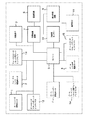
まず図2には、本発明の実施形態であるデジタルカメラ(光学装置)における電気回路構成を示している。
【0013】
この図において、1は撮影光学系のズームレンズ(撮影レンズ)を駆動するズームレンズ駆動モータ、12はズームレンズがズームリセット位置を通過したときの切り換わりを検出するズームレンズリセット用フォトインタラプタである。
【0014】
2は撮影光学系のフォーカスレンズ(撮影レンズ)を駆動するフォーカスレンズ駆動モータ、13はフォーカスレンズがフォーカスリセット位置を通過したときの切り換わりを検出するフォーカスレンズリセット用フォトインタラプタである。
【0015】
3はCCD等の撮像素子、4は撮像素子3からの信号を処理する信号処理回路、6は信号処理回路4にて処理された信号を記録する記録回路である。また、5は本カメラの動作全体を司るマイコンである。
【0016】
7は光学式のズームファインダーを駆動するファインダー駆動モータ、14はズームファインダーがファインダーリセット位置を通過したときの切り換わりを検出するファインダーリセット用フォトインタラプタである。
【0017】
8はズームストロボの照射角変更駆動を行うストロボ駆動モータ、15はズームストロボがストロボリセット位置を通過したときの切り換わりを検出するストロボリセット用フォトインタラプタである。なお、マイコン5およびフォトインタラプタ12〜15により請求の範囲にいう制御手段が構成される。
【0018】
9はLCD等を含む表示・再生回路である。10は本カメラに加わった落下等による振動(衝撃的振動)を検出するための加速度センサー(振動検出手段)である。11は本カメラにおいて各種操作入力を行うための操作部材である。
【0019】
このように構成されるカメラにおいて、操作部材11により電源が投入されると、マイコン5は、ズームレンズ、フォーカスレンズ、ズームファインダー、ズームストロボをそれぞれの駆動モータ1,2,7,8とリセット用フォトインタラプタ12,13,14,15とを用いて、各リセット位置が検出される所定の初期位置まで駆動する。
【0020】
その後、操作部材11を通じてテレ側またはワイド側にズーム倍率を可変させる操作が行われると、ズームレンズ、フォーカスレンズ、ズームファインダーおよびズームストロボをそれぞれの駆動モータ1,2,7,8を駆動して移動させる。
【0021】
そして、操作部材11にてレリーズ操作が行われると、撮影動作を行う。この撮影動作により、撮像素子3に結像された光学像が光電変換される。光電変換された信号は、信号処理回路4による電気的な処理が加えられ、記録回路6に記録されるとともに表示・再生回路9にて画像として表示される。
【0022】
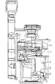
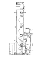
図1には、本カメラにおける撮影光学系およびファインダー光学系の構成を示している。また、図10には、撮影光学系のズームレンズとフォーカスレンズのテレ端からワイド端までの間の移動軌跡を示している。
【0023】
22は第1群レンズとしてのフォーカスレンズを保持するフォーカス移動筒である。このフォーカスレンズはズームレンズに対するコンペンセータを兼ねており、第2および第4群のズームレンズが図10に示す移動軌跡に沿って直線的に移動するのに伴い同図の曲線に沿って移動する。
【0024】
図3には、フォーカス移動筒22とフォーカス駆動モータ2との関係を示している。フォーカス移動筒22は、ガイドバー32,33によって光軸方向にのみ移動可能に支持されている。また、フォーカス移動筒22にはラック23が取り付けられている。ラック23は不図示のバネによってステッピングモータであるフォーカス駆動モータ2と一体になったスクリューネジ軸31を挟む形でこのスクリューネジ軸31に噛み合っており、モータ2が回転してスクリューネジ軸31が回転すると、ラック23がフォーカス移動筒22およびフォーカスレンズと一体となって光軸方向に移動する。
【0025】
図6には、フォーカスレンズの部分の正面図を示している。フォーカス移動筒22に形成された遮光板部22aが、フォーカス移動筒22の移動によってフォーカスリセット用フォトインタラプタ13の投光部と受光部との間に出入りして投・受光部間を遮光した状態と遮光しない状態とになることにより、フォトインタラプタ13の出力が変化する。そしてその出力をマイコン5が検知して、遮光した状態から遮光されない状態に切り換わった位置をフォーカスリセット位置とする。
【0026】
図4には、ラック部材23とスクリューネジ軸31の詳細を示している。図4(A)の状態では、ラック23は図中左側の4つの歯23aと、不図示のばねにより押されて弾圧変形した可動な右側の1つの歯23bとによってスクリューネジ軸31に噛み合っている。
【0027】
この状態でカメラに強い衝撃等の振動が加わった場合、フォーカス移動筒22に大きな力が加わり、ラック23の歯23aがスクリューネジ軸31の歯を乗り越えようとするため、歯23aと歯23bとの間の間隔が開き、図4(B)に示すように、ラック23が噛み合いが緩む方向に移動する。
【0028】
23cはラック23が歯を乗り越えるのを抑える対抗歯であるが、衝撃が強い場合には対抗歯23cの存在にもかかわらずいくつかのスクリューネジ軸31の歯を乗り越え(以下、これを歯飛びという)、図4(C)に示すように、移動したラック23の歯23aがスクリューネジ軸31と噛み合って静止する。
【0029】
図1において、21はズームレンズを保持するズーム移動筒である。図7には、このズーム移動筒71とズーム駆動モータ1との関係を示している。ズーム移動筒21は、ガイドバー74,75によって光軸方向にのみ移動可能に支持されている。また、ズーム移動筒21にはラック73が取り付けられている。ラック73は不図示のバネによってステッピングモータであるズーム駆動モータ1と一体になったスクリューネジ軸72を挟む形でこのスクリューネジ軸72に噛み合っており、モータ1が回転してスクリューネジ軸72が回転すると、ラック73がズーム移動筒21およびズームレンズと一体となって光軸方向に移動する。
【0030】
ズーム移動筒21には遮光板部21aが形成されており、この遮光板部21aが、ズーム移動筒21の移動によってズームリセット用フォトインタラプタ12の投光部と受光部との間に出入りして投・受光部間を遮光した状態と遮光しない状態とになることにより、フォトインタラプタ12の出力が変化する。そしてその出力をマイコン5が検知して、遮光した状態から遮光されない状態に切り換わった位置をズームリセット位置とする。
【0031】
カメラに強い衝撃等の振動が加わった場合におけるズーム移動筒21に取り付けられたラック73とスクリューネジ軸72との関係は、フォーカス移動筒22に取り付けられたラック23とスクリューネジ軸31との関係と同様である。
【0032】
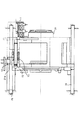
図8には、ズームファインダーの構成を示している。ファインダ駆動モータ7の回転により、図の紙面奥側に配置された不図示のファインダーカム板が駆動され、ファインダーのズームレンズ81が光軸方向に移動する。
【0033】
撮影光学系と同様に、ファインダーズームレンズ81を保持する移動筒には遮光板部81aが形成されており、この遮光板部81aが、移動筒の移動によってファインダーリセット用フォトインタラプタ14の投光部と受光部との間に出入りして投・受光部間を遮光した状態と遮光しない状態とになることにより、フォトインタラプタ14の出力が変化する。そしてその出力をマイコン5が検知して、遮光した状態から遮光されない状態に切り換わった位置をファインダーリセット位置とする。
【0034】
このズームファインダーには、カメラに強い衝撃等の振動が加わった場合、ファインダーカム板とファインダ駆動モータ7との間の係合関係にずれが生じる可能性がある点で、フォーカス移動筒22に取り付けられたラック23とスクリューネジ軸31との関係と同様の問題がある。
【0035】
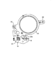
図9には、ズームストロボの構成を示している。このズームストロボは、キセノン管91と反射笠92とから構成される光源部と、この光源部を保持するホルダー94と、このホルダー94を光軸方向にガイドするガイド軸96と、ストロボ駆動用モータ8に一体的に設けられたスクリューネジ軸8aと、ホルダー94に取り付けられてスクリューネジ軸8aに噛み合うラック95とから構成されている。ストロボ駆動用モータ8の駆動によりスクリューネジ軸8aが回転すると、このスクリューネジ軸8aとラック95との噛合作用によってホルダー94が光軸方向前後に移動する。
【0036】
ズームストロボの前端には拡散板97が保持されており、この拡散板97とホルダー94(つまりは光源部)との間隔を変えることによりストロボ照射角が変化する。
【0037】
ホルダー94には撮影光学系の移動筒と同様に遮光板部93が形成されており、この遮光板部93が、ホルダー94の移動によってストロボリセット用フォトインタラプタ15の投光部と受光部との間に出入りして投・受光部間を遮光した状態と遮光しない状態とになることにより、フォトインタラプタ15の出力が変化する。そしてその出力をマイコン5が検知して、遮光した状態から遮光されない状態に切り換わった位置をストロボリセット位置とする。
【0038】
カメラに強い衝撃等の振動が加わった場合におけるホルダー94に取り付けられたラック95とスクリューネジ軸8aとの関係は、フォーカス移動筒22に取り付けられたラック23とスクリューネジ軸31との関係と同様である。
【0039】
図5には、本カメラの動作フローチャートを示している。ステップ51にて電源スイッチが投入されると、ステップ52にてカメラの初期化が行われ、撮影光学系のズームレンズ、フォーカスレンズ、ズームファインダーおよびズームストロボが前述した各リセット位置に駆動される。このとき、ズームファインダーとズームストロボは撮影光学系と同じ画角となるように予め調整しておく。
【0040】
この後、ステップ53にて操作部材11におけるズームスイッチの状態を検知して、ズームスイッチがオンになっている時には、ステップ54に進み、ズーミング動作状態になる。具体的には、ズームスイッチで指示されたテレまたはワイドの方向に、撮影光学系のズームレンズおよびフォーカスレンズを駆動するとともに、ズームファインダーおよびズームストロボを駆動する。
【0041】
ここで、コンペンセーターを兼ねるフォーカスレンズについて、ズームレンズの位置に対して、図10に示すフォーカス移動軌跡がマイコン5のメモリに記憶されている。このため、ズームレンズ移動に伴い、フォーカスレンズは常にズームレンズの位置に応じて無限から至近までの位置の間から出ないように駆動される。
【0042】
また、ズームファインダーとズームストロボについて、撮影光学系のズームレンズの移動に伴う画角変化と同様の画角変化を生じさせるための移動軌跡がマイコン5のメモリに記憶されている。このため、撮影光学系のズームレンズの移動に伴い、ズームファインダーとズームストロボは常にズームレンズの画角に合うようにマイコン5のメモリに記憶された移動軌跡に沿って駆動される。
【0043】
こうしてズーム動作が終了した場合又はステップ53にてズームスイッチの操作が検知されなかった場合は、ステップ55にてその時のズームレンズの位置をメモリに記憶する。
【0044】
この後、ステップ56で、加速度センサー10によりカメラに作用する振動の強さ(加速度)を検知する。この加速度センサー10は振動の大きさ・強さを測定できるものならばなにを用いてもよく、例えば振動ジャイロを用いてもよい。また、カメラに搭載された像振れ防止用の防振装置に使われる振動センサーと兼用してもよい。これにより、カメラの部品点数を増加させることなく、後述するリセット機能を持たせることができる。
【0045】
ここで加速度センサー10の出力がある閾値(所定レベル)を超えたときは、カメラに大きな衝撃が加わって、前述した歯飛びによりズームレンズ、フォーカスレンズおよびズームストロボ中のホルダー94が各スクリューネジ軸に対して移動したおそれがあるとして、またズームファインダー中のファインダーカム板とファインダー駆動モータとの係合関係がずれたおそれがあるとして、カメラ初期化時と同様に、撮影光学系のズームレンズ、フォーカスレンズ、ズームファインダーおよびズームストロボを各リセット位置に復帰駆動する。
【0046】
撮影光学系のズームレンズとフォーカスレンズとが各リセット位置に復帰駆動されることにより、それぞれ衝撃によりずれたおそれのあるズームレンズとフォーカスレンズとの位置関係を適正状態である初期化状態に確実に戻すことができる。
【0047】
また、ズームファインダーおよびズームストロボが各リセット位置に復帰駆動されることにより、それぞれ衝撃によりずれたおそれのある撮影光学系の画角とファインダーの画角およびストロボの照射角との関係を適正状態である初期化状態に確実に戻すことができる。
【0048】
こうしてステップ57にて各リセット位置への復帰駆動を行った後、ステップ58にて、ただちにズームレンズ、フォーカスレンズ、ズームファインダーおよびズームストロボを各リセット位置からステップ55にて記憶した各位置に駆動する。これにより、ズームレンズ、フォーカスレンズ、ズームファインダーおよびズームストロボを衝撃が加わる前の状態に自動的に復帰させることができる。
【0049】
続いて、ステップ59にてレリーズスイッチがONされたか否かを判定し、レリーズスイッチがONされたときには、ステップ60に進んで、AE・AFといった撮影準備動作を行い、続いてステップ61にて撮影動作を行う。レリーズスイッチがONされていないときは、ステップ53に戻る。
【0050】
なお、本実施形態では、衝撃が加わったときに、撮影光学系のズームレンズ、フォーカスレンズだけでなく、ズームファインダーおよびズームストロボをもリセット動作させる場合について説明したが、例えばズームファインダーやズームストロボは機構上衝撃に強い場合には、撮影光学系側のレンズだけをリセット動作させ衝撃を受ける前の位置に復帰するようにしてもよい。この場合、リセット動作にかかる時間と消費電力を節約することができる。
【0051】
また、本実施形態では、デジタルカメラについて説明したが、本発明は、光学式ファインダーを有する銀塩カメラ、ビデオカメラにも適用することができる。また、本発明は、可動光学素子を備えた各種光学装置に適用することができる。
【0052】
【発明の効果】
以上説明したように、本発明によれば、装置本体に閾値(所定レベル)を超える振動(衝撃的振動等)が加わった場合、検出振動が閾値(所定レベル)を超える前の光学素子(ズームレンズ、フォーカスレンズ、光学ファインダー、ズームストロボ)の位置を記憶し、光学素子を初期位置に戻した後に、この光学素子を記憶した位置に駆動するので、光学素子の位置ずれによる影響を防止し、かつ振動が加わる前と同じ状態で撮影を続行することができる。
【図面の簡単な説明】
【図1】本発明の実施形態であるデジタルカメラにおける撮影レンズと光学式ファインダーの断面図。
【図2】上記デジタルカメラの電気回路ブロック図。
【図3】上記撮影レンズにおけるフォーカス移動筒とフォーカス駆動モータとの関係を示す図。
【図4】上記フォーカス移動筒のラックとフォーカス駆動モータのスクリューネジ軸との関係を示す拡大図。
【図5】上記デジタルカメラの動作フローチャート。
【図6】上記フォーカス移動筒周辺の正面図。
【図7】上記撮影レンズにおけるズーム移動筒とズーム駆動モータとの関係を示す図。
【図8】上記デジタルカメラにおける光学式ズームファインダーの構成図。
【図9】上記デジタルカメラにおけるズームストロボの構成図。
【図10】上記撮影レンズの移動軌跡を示す図。
【符号の説明】
21 ズーム移動筒
22 フォーカス移動筒
12,13,14,15 フォトインタラプタ
23,73 ラック
31,72,8a スクリューネジ軸
91 キセノン管
92 反射笠[0001]
BACKGROUND OF THE INVENTION
The present invention relates to an optical apparatus having a movable optical element such as a silver salt camera, a digital camera, a video camera and the like.
[0002]
[Prior art]
An imaging optical system and an optical viewfinder in a camera are configured to drive several lenses in the optical axis direction for zooming, focusing, and the like. Then, as the drive mechanism for driving the lens, a screw shaft threaded to the drive shaft of the stepping motor, engagement with the rack attached to the movable lens frame that is guided in the optical axis direction by the guide bar, rotation of the stepping motor In some cases, the lens is driven by the meshing action of the screw screw shaft and the rack.
[0003]
In this case, a memory such as a computer stores the same cam locus as when the zoom lens or focus lens (compensator lens) is driven by the cam barrel, and the zoom lens or focus lens is It is moved and zoomed by computer control along the cam locus.
[0004]
Further, when using the drive mechanism as described above, the screw screw shaft and the rack are disengaged when subjected to shock vibration due to dropping or the like, and the movement of the moving lens group with respect to the screw screw shaft due to the vibration is allowed. By configuring, it is often the case that a failure due to the biting between the rack and the screw screw shaft does not occur at the time of impact.
[0005]
[Problems to be solved by the invention]
However, as described above, in the case of using a drive mechanism configured to perform the zoom operation by the engagement of the screw screw shaft and the rack and to disengage the screw screw shaft and the rack by shock vibration, the zoom lens or the When the meshing position of the rack on the focus lens side and the screw screw shaft is shifted, the zoom lens and the focus lens may be out of the cam locus and the focus may be shifted.
[0006]
Also, when zooming the optical viewfinder and shooting optical system independently, when the zoom lens is displaced due to impact, the relationship between the viewfinder and the shooting optical system shifts, and the viewfinder matches the angle of view of the shooting optical system. There is also a risk that the angle of view cannot be obtained.
[0007]
Similarly, the relationship between the zoom state of the photographing optical system and the irradiation angle of the zoom strobe may deviate, and there is a possibility that proper flash irradiation may not be performed on the subject.
[0008]
[Means for Solving the Problems]
In order to solve the above problems, in the present invention, in an optical device having an optical element that can move with reference to an initial position, vibration detection means for detecting vibration applied to the main body of the apparatus, and detection by the vibration detection means. Control means for moving the optical element back to the initial position when the vibration exceeds a threshold value (predetermined level) and then moving the optical element to the position of the stored optical element when the vibration exceeds the threshold value ; Provided.
[0012]
DETAILED DESCRIPTION OF THE INVENTION
First, FIG. 2 shows an electric circuit configuration in a digital camera (optical apparatus) according to an embodiment of the present invention.
[0013]
In this figure, reference numeral 1 denotes a zoom lens driving motor for driving a zoom lens (photographing lens) of the photographing optical system, and
[0014]
Reference numeral 2 denotes a focus lens driving motor that drives a focus lens (photographing lens) of the photographing optical system, and
[0015]
3 is an image sensor such as a CCD, 4 is a signal processing circuit for processing a signal from the image sensor 3, and 6 is a recording circuit for recording a signal processed by the signal processing circuit 4. A
[0016]
Reference numeral 7 denotes a finder drive motor for driving the optical zoom finder, and
[0017]
[0018]
[0019]
In the camera configured as described above, when the
[0020]
Thereafter, when an operation of changing the zoom magnification to the tele side or the wide side is performed through the
[0021]
When a release operation is performed with the
[0022]
FIG. 1 shows a configuration of a photographing optical system and a finder optical system in the camera. FIG. 10 shows the movement locus of the zoom lens and focus lens of the photographing optical system from the tele end to the wide end.
[0023]
[0024]
FIG. 3 shows the relationship between the
[0025]
FIG. 6 shows a front view of the focus lens portion. A state in which the light shielding
[0026]
FIG. 4 shows details of the
[0027]
In this state, when a strong vibration such as a shock is applied to the camera, a large force is applied to the
[0028]
23c is a counter tooth that suppresses the
[0029]
In FIG. 1,
[0030]
The
[0031]
The relationship between the
[0032]
FIG. 8 shows the configuration of the zoom finder. The rotation of the finder drive motor 7 drives a finder cam plate (not shown) arranged on the back side of the drawing in the drawing, and the
[0033]
Similar to the imaging optical system, the movable barrel that holds the
[0034]
This zoom finder is attached to the
[0035]
FIG. 9 shows a configuration of the zoom strobe. The zoom strobe includes a light source unit composed of a
[0036]
A
[0037]
A light
[0038]
The relationship between the
[0039]
FIG. 5 shows an operation flowchart of the camera. When the power switch is turned on in step 51, the camera is initialized in step 52, and the zoom lens, focus lens, zoom finder, and zoom strobe of the photographing optical system are driven to the reset positions described above. At this time, the zoom finder and the zoom strobe are adjusted in advance so as to have the same angle of view as the photographing optical system.
[0040]
Thereafter, in step 53, the state of the zoom switch in the
[0041]
Here, with respect to the focus lens that also serves as the compensator, the focus movement locus shown in FIG. 10 is stored in the memory of the
[0042]
Further, for the zoom finder and the zoom strobe, the movement trajectory for causing the same change in the angle of view as the movement of the zoom lens of the photographing optical system is stored in the memory of the
[0043]
When the zoom operation is completed in this way, or when the operation of the zoom switch is not detected in step 53, the zoom lens position at that time is stored in the memory in step 55.
[0044]
Thereafter, in step 56, the
[0045]
Here, when the output of the
[0046]
The zoom lens and focus lens of the photographic optical system are driven back to their respective reset positions, ensuring that the positional relationship between the zoom lens and focus lens, which may have been displaced due to impact, is in the proper initialization state. Can be returned.
[0047]
In addition, the zoom finder and zoom strobe are driven back to their respective reset positions, so that the relationship between the angle of view of the photographic optical system, which may have been displaced due to impact, the angle of view of the finder, and the illumination angle of the strobe in an appropriate state. A certain initialization state can be reliably restored.
[0048]
Thus, after returning to the reset positions in step 57, the zoom lens, focus lens, zoom finder, and zoom strobe are immediately driven from the reset positions to the positions stored in step 55 in step 58. . Thereby, the zoom lens, the focus lens, the zoom finder, and the zoom strobe can be automatically returned to the state before the impact is applied.
[0049]
Subsequently, in step 59, it is determined whether or not the release switch is turned on. When the release switch is turned on, the process proceeds to step 60 to perform a shooting preparation operation such as AE / AF, and then in step 61. Perform the action. If the release switch is not turned on, the process returns to step 53.
[0050]
In this embodiment, the case where the zoom finder and the zoom strobe are reset when not only the zoom lens and the focus lens of the photographing optical system when an impact is applied has been described. If the mechanism is strong against an impact, only the lens on the photographing optical system side may be reset to return to the position before the impact. In this case, the time and power consumption required for the reset operation can be saved.
[0051]
In this embodiment, a digital camera has been described. However, the present invention can also be applied to a silver salt camera and a video camera having an optical viewfinder. Further, the present invention can be applied to various optical devices provided with a movable optical element.
[0052]
【The invention's effect】
As described above, according to the present invention, when vibration exceeding the threshold (predetermined level) (impact vibration or the like) is applied to the apparatus body, the optical element (zoom) before the detected vibration exceeds the threshold (predetermined level). Lens, focus lens, optical viewfinder, zoom strobe) position, and after returning the optical element to its initial position, this optical element is driven to the stored position, preventing the effects of optical element displacement, In addition, it is possible to continue shooting in the same state as before the vibration was applied.
[Brief description of the drawings]
FIG. 1 is a cross-sectional view of a photographing lens and an optical viewfinder in a digital camera according to an embodiment of the present invention.
FIG. 2 is an electric circuit block diagram of the digital camera.
FIG. 3 is a diagram illustrating a relationship between a focus moving cylinder and a focus drive motor in the photographing lens.
FIG. 4 is an enlarged view showing the relationship between the rack of the focus moving cylinder and the screw screw shaft of the focus drive motor.
FIG. 5 is an operation flowchart of the digital camera.
FIG. 6 is a front view around the focus moving cylinder.
FIG. 7 is a diagram illustrating a relationship between a zoom moving cylinder and a zoom drive motor in the photographing lens.
FIG. 8 is a configuration diagram of an optical zoom finder in the digital camera.
FIG. 9 is a configuration diagram of a zoom strobe in the digital camera.
FIG. 10 is a diagram showing a movement locus of the photographing lens.
[Explanation of symbols]
21
Claims (6)
装置本体に加わった振動を検出する振動検出手段と、
前記ズームレンズ及び前記フォーカスレンズの位置を記憶し、前記振動検出手段により検出された振動が閾値を超えたときに、前記ズームレンズ及び前記フォーカスレンズを、前記初期位置にそれぞれ復帰させた後に、前記振動が前記閾値を超えた時点で記憶している前記ズームレンズ及び前記フォーカスレンズの位置に移動させる制御手段とを有することを特徴とする光学装置。A zoom lens that can move in the optical axis direction with reference to the initial position during zooming, and a zoom lens that is driven during zooming. A photographing optical system including a focus lens movable in the optical axis direction as
Vibration detecting means for detecting vibration applied to the apparatus body;
Storing a position of the zoom lens and the focus lens, when the detected vibration exceeds the threshold value by the vibration detecting means, said zoom lens and said focus lens, in after returning to each of the initial position, the An optical apparatus comprising: control means for moving to a position of the zoom lens and the focus lens stored when the vibration exceeds the threshold value .
初期位置を基準として前記撮影光学系のズーム動作に伴ってズーム動作を行う光学ファインダーと、
装置本体に加わった振動を検出する振動検出手段と、
前記撮影光学系及び前記光学ファインダーの位置を記憶し、前記振動検出手段により検出された振動が閾値を超えたときに、前記撮影光学系及び前記光学ファインダーを、前記初期位置にそれぞれ復帰させた後に、前記振動が前記閾値を超えた時点で記憶している前記撮影光学系及び前記光学ファインダーの位置に移動させる制御手段とを有することを特徴とする光学装置。An imaging optical system that can move in the optical axis direction with reference to the initial position,
An optical viewfinder that performs a zoom operation with a zoom operation of the photographing optical system with reference to an initial position;
Vibration detecting means for detecting vibration applied to the apparatus body;
Storing the position of the photographing optical system and the optical viewfinder, the when the detected vibration exceeds the threshold value by the vibration detecting means, said imaging optical system and the optical viewfinder, the after returning to each of the initial position An optical apparatus comprising: a control unit configured to move to the position of the photographing optical system and the optical finder stored when the vibration exceeds the threshold value .
初期位置を基準として前記撮影光学系のズーム動作に伴って照明光の照射角を変更可能なズームストロボと、
装置本体に加わった振動を検出する振動検出手段と、
前記撮影光学系及び前記ズームストロボの位置を記憶し、前記振動検出手段により検出された振動が閾値を超えたときに、前記撮影光学系及び前記ズームストロボを、前記初期位置にそれぞれ復帰させた後に、前記振動が前記閾値を超えた時点で記憶している前記撮影光学系及び前記ズームストロボの位置に移動させる制御手段とを有することを特徴とする光学装置。An imaging optical system that can move in the optical axis direction with reference to the initial position,
A zoom strobe that can change the illumination angle of illumination light with the zoom operation of the photographing optical system with reference to the initial position;
Vibration detecting means for detecting vibration applied to the apparatus body;
Storing the position of the photographing optical system and the zoom strobe, the when the detected vibration exceeds the threshold value by the vibration detecting means, said imaging optical system and the zoom strobe, after to return respectively to the initial position An optical apparatus comprising: the photographing optical system that is stored when the vibration exceeds the threshold value; and a control unit that moves to the position of the zoom strobe .
前記連結手段が、前記撮影光学系内に取り付けられたラックであることを特徴とする請求項4に記載の光学装置。The drive member is a screw screw shaft that is rotationally driven,
The optical apparatus according to claim 4, wherein the connecting unit is a rack attached in the photographing optical system.
前記振動検出手段を、前記像振れ防止制御を行うために振れを検出する手段と兼用したことを特徴とする請求項1ないし5のいずれか1項に記載の光学装置。It is possible to perform image blur prevention control for displacing the shake correction device in the photographing optical system in order to detect the shake of the apparatus main body and prevent the image blur.
6. The optical apparatus according to claim 1, wherein the vibration detecting unit is also used as a unit for detecting a shake in order to perform the image blur prevention control.
Priority Applications (1)
| Application Number | Priority Date | Filing Date | Title |
|---|---|---|---|
| JP2000035497A JP4587147B2 (en) | 2000-02-14 | 2000-02-14 | Optical device |
Applications Claiming Priority (1)
| Application Number | Priority Date | Filing Date | Title |
|---|---|---|---|
| JP2000035497A JP4587147B2 (en) | 2000-02-14 | 2000-02-14 | Optical device |
Publications (3)
| Publication Number | Publication Date |
|---|---|
| JP2001228500A JP2001228500A (en) | 2001-08-24 |
| JP2001228500A5 JP2001228500A5 (en) | 2007-03-29 |
| JP4587147B2 true JP4587147B2 (en) | 2010-11-24 |
Family
ID=18559686
Family Applications (1)
| Application Number | Title | Priority Date | Filing Date |
|---|---|---|---|
| JP2000035497A Expired - Fee Related JP4587147B2 (en) | 2000-02-14 | 2000-02-14 | Optical device |
Country Status (1)
| Country | Link |
|---|---|
| JP (1) | JP4587147B2 (en) |
Families Citing this family (9)
| Publication number | Priority date | Publication date | Assignee | Title |
|---|---|---|---|---|
| KR100918821B1 (en) | 2003-03-05 | 2009-09-25 | 삼성전자주식회사 | CCTV camera integrated with zoom lens having the function of position correcting and correction method thereof |
| JP2008309809A (en) * | 2005-10-03 | 2008-12-25 | Nikon Corp | Camera |
| JP4850587B2 (en) * | 2006-05-30 | 2012-01-11 | キヤノン株式会社 | Optical equipment |
| JP5424621B2 (en) * | 2008-11-25 | 2014-02-26 | キヤノン株式会社 | Imaging apparatus and lens control method |
| JP5524509B2 (en) * | 2009-05-11 | 2014-06-18 | パナソニック株式会社 | Camera, portable terminal device and lens position control method |
| JP5401429B2 (en) * | 2010-10-20 | 2014-01-29 | 株式会社タムロン | Optical element position detection / control device and imaging device |
| JP5911216B2 (en) * | 2011-06-29 | 2016-04-27 | キヤノン株式会社 | Optical apparatus and control method thereof |
| JP6161361B2 (en) * | 2013-03-29 | 2017-07-12 | キヤノン株式会社 | Rack and optical apparatus using the same |
| JP2022094584A (en) | 2020-12-15 | 2022-06-27 | 株式会社Jvcケンウッド | Imaging apparatus and imaging method |
Family Cites Families (8)
| Publication number | Priority date | Publication date | Assignee | Title |
|---|---|---|---|---|
| JP2769189B2 (en) * | 1989-06-13 | 1998-06-25 | ウエスト電気株式会社 | Electric zoom camera |
| JPH07261071A (en) * | 1994-03-18 | 1995-10-13 | Olympus Optical Co Ltd | Camera |
| JP2963006B2 (en) * | 1994-06-01 | 1999-10-12 | 三洋電機株式会社 | Camera device |
| JPH09211556A (en) * | 1996-01-31 | 1997-08-15 | Fuji Photo Optical Co Ltd | Interlocking mechanism for zoom finder and zoom stroboscope |
| JPH09218446A (en) * | 1996-02-09 | 1997-08-19 | Nikon Corp | Camera provided with impact information storage function |
| JPH11142715A (en) * | 1997-11-07 | 1999-05-28 | Nikon Corp | Zoom camera |
| JPH11212145A (en) * | 1998-01-29 | 1999-08-06 | Olympus Optical Co Ltd | Camera |
| JPH11341318A (en) * | 1998-05-25 | 1999-12-10 | Canon Inc | Camera system |
-
2000
- 2000-02-14 JP JP2000035497A patent/JP4587147B2/en not_active Expired - Fee Related
Also Published As
| Publication number | Publication date |
|---|---|
| JP2001228500A (en) | 2001-08-24 |
Similar Documents
| Publication | Publication Date | Title |
|---|---|---|
| JP5013078B2 (en) | Lens barrel and imaging device | |
| JP4632817B2 (en) | Lens barrel, camera, portable information terminal, and image input device | |
| US7515815B2 (en) | Imaging device having an optical image stabilizer | |
| JP4912817B2 (en) | Lens barrel, camera, portable information terminal device, and image input device | |
| JP2004198742A (en) | Lens device | |
| CN107589510B (en) | Lens barrel | |
| JP2005086669A (en) | Camera | |
| JP4587147B2 (en) | Optical device | |
| KR101532603B1 (en) | Apparatus for reducing mirror bound, photographing apparatus comprising the same, and photographing method for the same | |
| JP4886503B2 (en) | Lens barrel | |
| JP3362490B2 (en) | Lens barrel | |
| JP4683795B2 (en) | Lens moving device | |
| JP3158753B2 (en) | Lens drive | |
| JP2009217014A (en) | Lens barrel and photographing device | |
| JP4684766B2 (en) | Lens barrel, lens driving device, camera, and portable information terminal device | |
| JP2001264616A (en) | Lens device | |
| JP2020188348A (en) | Imaging device, image monitoring system, and control method of imaging device | |
| JP7166949B2 (en) | CONTROL DEVICE, AND LENS DEVICE AND IMAGING DEVICE INCLUDING THE SAME | |
| JP2002341226A (en) | Lens controller | |
| JP6347658B2 (en) | Lens barrel, optical device, and imaging apparatus | |
| JP3038954B2 (en) | Camera device | |
| JP4311694B2 (en) | Lens device and camera | |
| KR101477534B1 (en) | Digital single lens reflex camera | |
| JP2021096382A (en) | Optical device, lens device, and imaging device | |
| JP2014016514A (en) | Camera system |
Legal Events
| Date | Code | Title | Description |
|---|---|---|---|
| A521 | Request for written amendment filed |
Free format text: JAPANESE INTERMEDIATE CODE: A523 Effective date: 20070213 |
|
| A621 | Written request for application examination |
Free format text: JAPANESE INTERMEDIATE CODE: A621 Effective date: 20070213 |
|
| RD03 | Notification of appointment of power of attorney |
Free format text: JAPANESE INTERMEDIATE CODE: A7423 Effective date: 20081010 |
|
| RD05 | Notification of revocation of power of attorney |
Free format text: JAPANESE INTERMEDIATE CODE: A7425 Effective date: 20081201 |
|
| A131 | Notification of reasons for refusal |
Free format text: JAPANESE INTERMEDIATE CODE: A131 Effective date: 20100223 |
|
| A521 | Request for written amendment filed |
Free format text: JAPANESE INTERMEDIATE CODE: A523 Effective date: 20100422 |
|
| A131 | Notification of reasons for refusal |
Free format text: JAPANESE INTERMEDIATE CODE: A131 Effective date: 20100602 |
|
| A521 | Request for written amendment filed |
Free format text: JAPANESE INTERMEDIATE CODE: A523 Effective date: 20100716 |
|
| TRDD | Decision of grant or rejection written | ||
| A01 | Written decision to grant a patent or to grant a registration (utility model) |
Free format text: JAPANESE INTERMEDIATE CODE: A01 Effective date: 20100825 |
|
| A01 | Written decision to grant a patent or to grant a registration (utility model) |
Free format text: JAPANESE INTERMEDIATE CODE: A01 |
|
| A61 | First payment of annual fees (during grant procedure) |
Free format text: JAPANESE INTERMEDIATE CODE: A61 Effective date: 20100906 Free format text: JAPANESE INTERMEDIATE CODE: A61 Effective date: 20100831 |
|
| R150 | Certificate of patent or registration of utility model |
Free format text: JAPANESE INTERMEDIATE CODE: R150 |
|
| FPAY | Renewal fee payment (event date is renewal date of database) |
Free format text: PAYMENT UNTIL: 20130917 Year of fee payment: 3 |
|
| FPAY | Renewal fee payment (event date is renewal date of database) |
Free format text: PAYMENT UNTIL: 20130917 Year of fee payment: 3 |
|
| FPAY | Renewal fee payment (event date is renewal date of database) |
Free format text: PAYMENT UNTIL: 20130917 Year of fee payment: 3 |
|
| FPAY | Renewal fee payment (event date is renewal date of database) |
Free format text: PAYMENT UNTIL: 20130917 Year of fee payment: 3 |
|
| LAPS | Cancellation because of no payment of annual fees |