JP4585737B2 - Fuel cell - Google Patents
Fuel cell Download PDFInfo
- Publication number
- JP4585737B2 JP4585737B2 JP2002235121A JP2002235121A JP4585737B2 JP 4585737 B2 JP4585737 B2 JP 4585737B2 JP 2002235121 A JP2002235121 A JP 2002235121A JP 2002235121 A JP2002235121 A JP 2002235121A JP 4585737 B2 JP4585737 B2 JP 4585737B2
- Authority
- JP
- Japan
- Prior art keywords
- electrode
- flow path
- electrolyte membrane
- fuel cell
- flat portion
- Prior art date
- Legal status (The legal status is an assumption and is not a legal conclusion. Google has not performed a legal analysis and makes no representation as to the accuracy of the status listed.)
- Expired - Fee Related
Links
Images


Classifications
-
- Y—GENERAL TAGGING OF NEW TECHNOLOGICAL DEVELOPMENTS; GENERAL TAGGING OF CROSS-SECTIONAL TECHNOLOGIES SPANNING OVER SEVERAL SECTIONS OF THE IPC; TECHNICAL SUBJECTS COVERED BY FORMER USPC CROSS-REFERENCE ART COLLECTIONS [XRACs] AND DIGESTS
- Y02—TECHNOLOGIES OR APPLICATIONS FOR MITIGATION OR ADAPTATION AGAINST CLIMATE CHANGE
- Y02E—REDUCTION OF GREENHOUSE GAS [GHG] EMISSIONS, RELATED TO ENERGY GENERATION, TRANSMISSION OR DISTRIBUTION
- Y02E60/00—Enabling technologies; Technologies with a potential or indirect contribution to GHG emissions mitigation
- Y02E60/30—Hydrogen technology
- Y02E60/50—Fuel cells
Description
【0001】
【発明の属する技術分野】
本発明は、固体高分子電解質膜の両側にそれぞれ電極を設けた電解質膜・電極構造体と、前記電解質膜・電極構造体を挟持するとともに、各電極に対向する面にそれぞれ所定の反応ガスを供給する反応ガス流路が形成された一組の金属製セパレータとを備える燃料電池に関する。
【0002】
【従来の技術】
例えば、固体高分子型燃料電池は、高分子イオン交換膜(陽イオン交換膜)からなる固体高分子電解質膜を採用している。この燃料電池は、固体高分子電解質膜の両側に、それぞれ電極触媒と多孔質カーボンからなるアノード側電極およびカソード側電極を対設して構成される電解質膜・電極構造体を、セパレータ(バイポーラ板)によって挟持することにより構成されている。通常、この燃料電池を所定数だけ積層した燃料電池スタックが使用されている。
【0003】
この種の燃料電池において、アノード側電極に供給された燃料ガス(反応ガス)、例えば、主に水素を含有するガス(以下、水素含有ガスともいう)は、電極触媒上で水素がイオン化され、電解質膜を介してカソード側電極側へと移動する。その間に生じた電子が外部回路に取り出され、直流の電気エネルギとして利用される。なお、カソード側電極には、酸化剤ガス(反応ガス)、例えば、主に酸素を含有するガスあるいは空気(以下、酸素含有ガスともいう)が供給されているために、このカソード側電極において、水素イオン、電子および酸素が反応して水が生成される。
【0004】
上記の燃料電池では、セパレータの面内に、アノード側電極に対向して燃料ガスを流すための燃料ガス流路(反応ガス流路)と、カソード側電極に対向して酸化剤ガスを流すための酸化剤ガス流路(反応ガス流路)とが設けられている。また、セパレータ間には、必要に応じて冷却媒体を流すための冷却媒体流路が前記セパレータの面方向に沿って設けられている。
【0005】
この種のセパレータは、通常、カーボン系材料で構成されているが、前記カーボン系材料では、強度等の要因で薄肉化が図れないという不具合が指摘されている。そこで、最近、この種のカーボン製セパレータよりも強度に優れかつ薄肉化が容易な金属薄板製のセパレータ(以下、金属製セパレータともいう)を用い、この金属製セパレータにプレス加工を施して所望の反応ガス流路を成形することにより、該金属製セパレータの厚さの減少を図って燃料電池全体を小型化かつ軽量化する工夫がなされている。
【0006】
例えば、図11に示す燃料電池1は、アノード側電極2とカソード側電極3との間に電解質膜4が介装されることにより構成された電解質膜・電極構造体5と、前記電解質膜・電極構造体5を挟持する一組の金属製のセパレータ6a、6bとを備えている。
【0007】
セパレータ6aには、アノード側電極2に対向する面に燃料ガス(例えば、水素含有ガス)を供給するための燃料ガス流路7aが設けられる一方、セパレータ6bには、カソード側電極3に対向する面に酸化剤ガス(例えば、空気等の酸素含有ガス)を供給するための酸化剤ガス流路7bが設けられている。セパレータ6a、6bには、アノード側電極2およびカソード側電極3に当接する平坦部8a、8bが設けられるとともに、前記平坦部8a、8bの裏面(当接面とは反対の面)側には、冷却媒体を流すための冷却媒体流路9a、9bが形成されている。
【0008】
【発明が解決しようとする課題】
しかしながら、上記の酸化剤ガス流路7bおよび燃料ガス流路7aでは、生成水の発生や反応ガスの消費等により、入口側から出口側に向かうにつれて相対湿度が上昇してしまう。このため、出口側が入口側よりも結露し易くなり、薄肉でかつ裏面に沿って冷却媒体が流れる金属製のセパレータ6a、6bでは、冷却効率が高くなって高湿度状態で結露が発生してしまう。
【0009】
特に、反応ガス出口側の平坦部8a、8bでは、裏面側に冷却媒体が直接流れているために当接面側が結露し易くなるとともに、反応ガスの流速が低下しているために結露水が排出され難く、滞留する場合が多い。従って、電解質膜・電極構造体5には、反応ガス出口側の平坦部8a、8bが当接する部分に対応して滞留水が発生し、この滞留水により反応ガスが拡散されない部分、すなわち、未反応面部分Sが存在してしまう。これにより、電解質膜・電極構造体5では、触媒反応に有効な面積が減少してしまい、良好かつ効率的な発電性能を維持することができないという問題が指摘されている。
【0010】
本発明はこの種の問題を解決するものであり、簡単な構成で、電極面内での反応生成水の結露を可及的に阻止することができ、良好な発電性能を確保することが可能な燃料電池を提供することを目的とする。
【0011】
【課題を解決するための手段】
本発明の請求項1に係る燃料電池では、固体高分子電解質膜の両側にそれぞれ電極を設けた電解質膜・電極構造体を、一組の金属製セパレータで挟持するとともに、前記金属製セパレータは、それぞれの電極に当接する平坦部と、前記平坦部を挟んで前記電極から離間することにより、反応ガス流路を形成する凹状部とを備えている。そして、平坦部は、反応ガス流路の上流から下流に向かって、電極に当接する幅寸法が小さくなるように設定されている。
【0012】
このため、例えば、生成水が多く発生して相対湿度が高くなり易い反応ガス流路の下流側では、金属製セパレータが電極に当接する面積を大幅に削減することができる。さらに、冷却媒体が電極に接する面積も小さくなり、電極面が冷却され難くなって結露の発生を抑制することが可能になる。これにより、滞留水による電極面の未反応面部分を有効に削減して前記電極面の反応有効面積を良好に確保することができ、濃度過電圧の上昇を抑えることが可能になる。
【0013】
一方、反応ガス流路の上流側では、相対湿度が低いために結露し難い。従って、金属製セパレータが電極に当接する平坦部の面積を大きく設定することにより、抵抗過電圧を有効に低減することが可能になる。このため、簡単な構成で、燃料電池の良好な発電性能を確実に維持することができる。
【0014】
【発明の実施の形態】
図1は、本発明の第1の実施形態に係る燃料電池10の要部分解斜視図である。
【0015】
燃料電池10は、電解質膜・電極構造体12と、前記電解質膜・電極構造体12を挟持する第1および第2金属製セパレータ14、16とを備える。電解質膜・電極構造体12と第1および第2金属製セパレータ14、16との間には、後述する連通孔の周囲および電極面(発電面)の外周を覆って、ガスケット等のシール部材18が介装されている。
【0016】
電解質膜・電極構造体12と第1および第2金属製セパレータ14、16の矢印B方向の一端縁部には、積層方向である矢印A方向に互いに連通して、酸化剤ガス、例えば、酸素含有ガスを供給するための酸化剤ガス供給連通孔20a、冷却媒体を排出するための冷却媒体排出連通孔22b、および燃料ガス、例えば、水素含有ガスを排出するための燃料ガス排出連通孔24bが、矢印C方向(鉛直方向)に配列して設けられる。
【0017】
電解質膜・電極構造体12と第1および第2金属製セパレータ14、16の矢印B方向の他端縁部には、矢印A方向に互いに連通して、燃料ガスを供給するための燃料ガス供給連通孔24a、冷却媒体を供給するための冷却媒体供給連通孔22a、および酸化剤ガスを排出するための酸化剤ガス排出連通孔20bが、矢印C方向に配列して設けられる。
【0018】
電解質膜・電極構造体12は、例えば、パーフルオロスルホン酸の薄膜に水が含浸されてなる固体高分子電解質膜26と、該固体高分子電解質膜26を挟持するアノード側電極28およびカソード側電極30とを備える。
【0019】
アノード側電極28およびカソード側電極30は、カーボンペーパー等からなるガス拡散層と、白金合金が表面に担持された多孔質カーボン粒子を前記ガス拡散層の表面に一様に塗布した電極触媒層とをそれぞれ有する。電極触媒層は、互いに固体高分子電解質膜26を介装して対向するように、前記固体高分子電解質膜26の両面に接合されている。シール部材18の中央部には、アノード側電極28およびカソード側電極30に対応して開口部34が形成されている。
【0020】
第1金属製セパレータ14の電解質膜・電極構造体12側の面14aには、例えば、矢印B方向に延在する複数本の溝部からなる酸化剤ガス流路36が設けられるとともに、この酸化剤ガス流路36は、酸化剤ガス供給連通孔20aと酸化剤ガス排出連通孔20bとに連通する。
【0021】
図2および図3に示すように、第1金属製セパレータ14は、電解質膜・電極構造体12のカソード側電極30に当接する平坦部38と、前記平坦部38を挟んで前記カソード側電極30から離間することにより酸化剤ガス流路36を形成する凹状部40とを備える。平坦部38は、第1金属製セパレータ14にプレス成形処理等を施すことにより一体成形されており、酸化剤ガス流路36の上流から下流に向かって(矢印B1方向)、カソード側電極30に当接する幅寸法Lが小さくなるように設定される(図4参照)。
【0022】
各平坦部38は、矢印C方向に所定間隔ずつ離間しかつ矢印B方向に互いに平行に設けられており、酸化剤ガス流路36の上流側である矢印B2方向先端側が、図5に示すように、最大幅寸法L1に設定された略台形状に構成される。平坦部38は、酸化剤ガス流路36の下流側である矢印B1方向先端部が、図6に示すように、最小幅寸法L2に設定された略円弧状に構成される。平坦部38の幅寸法Lは、最大幅寸法L1から最小幅寸法L2に向かって連続的にあるいは段階的に小さくなるように設定される。
【0023】
第2金属製セパレータ16の電解質膜・電極構造体12側の面16aには、燃料ガス供給連通孔24aと燃料ガス排出連通孔24bとに連通する燃料ガス流路42が形成される。この燃料ガス流路42は、矢印B方向に延在する複数本の溝部を備えている。第2金属製セパレータ16の面16bには、冷却媒体供給連通孔22aと冷却媒体排出連通孔22bとに連通する冷却媒体流路44が形成される。この冷却媒体流路44は、矢印B方向に延在する複数本の溝部を備えている。
【0024】
図7に示すように、第2金属製セパレータ16の面16a側には、電解質膜・電極構造体12のアノード側電極28に当接する平坦部46と、前記平坦部46を挟んで前記アノード側電極28から離間することにより燃料ガス流路42を形成する凹状部48とが設けられる。
【0025】
平坦部46は、矢印C方向に所定間隔ずつ離間し、かつ矢印B方向に互いに平行して延在している。各平坦部46は、燃料ガス流路42の上流から下流に向かって(矢印B1方向)、アノード側電極28に当接する幅寸法Lが小さくなるように設定される。この平坦部46は、第1金属製セパレータ14の平坦部38と同様に構成されており、その詳細な説明は省略する。
【0026】
このように構成される燃料電池10の動作について、以下に説明する。
【0027】
図1に示すように、燃料ガス供給連通孔24aに水素含有ガス等の燃料ガスが供給されるとともに、酸化剤ガス供給連通孔20aに酸素含有ガス等の酸化剤ガスが供給される。さらに、冷却媒体供給連通孔22aに純水やエチレングリコール、オイル等の冷却媒体が供給される。
【0028】
酸化剤ガスは、酸化剤ガス供給連通孔20aから第1金属製セパレータ14の酸化剤ガス流路36に導入され、電解質膜・電極構造体12を構成するカソード側電極30に沿って移動する。一方、燃料ガスは、燃料ガス供給連通孔24aから第2金属製セパレータ16の燃料ガス流路42に導入され、電解質膜・電極構造体12を構成するアノード側電極28に沿って移動する。
【0029】
従って、電解質膜・電極構造体12では、カソード側電極30に供給される酸化剤ガスと、アノード側電極28に供給される燃料ガスとが、電極触媒層内で電気化学反応により消費され、発電が行われる。
【0030】
次いで、アノード側電極28に供給されて消費された燃料ガスは、燃料ガス排出連通孔24bに沿って矢印A方向に排出される。同様に、カソード側電極30に供給されて消費された酸化剤ガスは、酸化剤ガス排出連通孔20bに沿って矢印A方向に排出される。
【0031】
また、冷却媒体供給連通孔22aに供給された冷却媒体は、第2金属製セパレータ16の冷却媒体流路44に導入された後、矢印B方向に沿って流通する。この冷却媒体は、電解質膜・電極構造体12を冷却した後、冷却媒体排出連通孔22bから排出される。
【0032】
ここで、例えば、電解質膜・電極構造体12を構成するカソード側電極30では、反応により生成水が発生し、この生成水が酸化剤ガスの流れ方向に沿って増加している。このため、第1金属製セパレータ14に形成される酸化剤ガス流路36では、出口側(酸化剤ガス排出連通孔20b側)に結露水が発生し易い。
【0033】
そこで、第1の実施形態では、酸化剤ガス流路36を構成する平坦部38が、酸化剤ガス流路36の上流から下流に向かってカソード側電極30に接触する幅寸法Lが小さくなるように構成されている(図3および図4参照)。このため、生成水が多く発生して相対湿度が高くなり易い酸化剤ガス流路36の下流側では、第1金属製セパレータ14がカソード側電極30に当接する平坦部38の面積を大幅に削減することができる。
【0034】
従って、カソード側電極30の滞留水による未反応面部分が、図6に示すように、最小幅寸法L2まで大幅に削減される。これにより、カソード側電極30の反応有効面積を良好に確保することが可能になり、濃度過電圧の上昇を抑えることができるという効果が得られる。
【0035】
一方、酸化剤ガス流路36の上流側では、相対湿度が低いために結露し難く、第1金属製セパレータ14がカソード側電極30に当接する平坦部38の面積を大きく設定することが可能になる。このため、酸化剤ガス流路36の上流側における抵抗過電圧を有効に低減することができるという利点がある。
【0036】
これにより、第1の実施形態では、特に、第1金属製セパレータ14が用いられる際、生成水の増加および酸化剤ガスの流速の低下に起因して結露水が排出され難い場合であっても、平坦部38の幅寸法Lを上流側から下流側に向かって小さくなるように設定することにより、簡単な構成で、未反応面部分を有効に削減することができ、燃料電池10の発電性能を確実に維持することが可能になる。
【0037】
なお、第2金属製セパレータ16に形成された燃料ガス流路42においても同様に、燃料ガスが消費されることによって上流側に比べて下流側の相対湿度が高くなり易い。その際、図7に示すように、平坦部46の幅寸法Lを、上流から下流に向かって小さくなるように設定するだけで、滞留水を大幅に削減して良好な発電性能を維持することができる。
【0038】
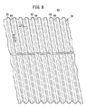
図8は、本発明の第2の実施形態に係る燃料電池を構成する第1金属製セパレータ60の一部拡大斜視図であり、図9は、前記第1金属製セパレータ60の一部断面説明図である。なお、第1の実施形態に係る燃料電池10と同一の構成要素には同一の参照符号を付して、その詳細な説明は省略する。また、以下に説明する第3の実施形態においても同様に、その詳細な説明は省略する。
【0039】
第1金属製セパレータ60は、電解質膜・電極構造体12を構成するカソード側電極30に当接する平坦部62と、前記平坦部62を挟んで前記カソード側電極30から離間することにより、酸化剤ガス流路36を形成する凹状部64とを備える。
【0040】
平坦部62は、酸化剤ガス流路36の上流から下流に向かってカソード側電極30に当接する幅寸法Lが小さくなるように設定される。平坦部62は、下流側の最小幅寸法L2を構成するために断面多角形状に設定されるとともに、この下流側の酸化剤ガス流路36の流路断面積が、上流側の前記酸化剤ガス流路36の流路断面積よりも同等以下に設定されている。
【0041】
これにより、第2の実施形態では、相対湿度が高くなる酸化剤ガス流路36の下流側に最小幅寸法L2に設定された平坦部62を設けることによって、滞留水を有効に削減して良好な発電性能を維持することができる等、第1の実施形態と同様の効果が得られる。
【0042】
しかも、第2の実施形態では、酸化剤ガス流路36の流路断面積が、上流から下流に向かって同等以下に設定されている。このため、酸化剤ガスの流速の低下を阻止するとともに、カソード側電極30の全面にわたって酸化剤ガスを円滑かつ確実に供給することが可能になり、発電性能を高く維持することができるという利点がある。
【0043】
図10は、参考例に係る燃料電池を構成する第1金属製セパレータ80の正面説明図である。
【0044】
第1金属製セパレータ80は、酸化剤ガスの流れ方向に平行して第1平坦部82と第2平坦部84とを交互に設けるとともに、前記第1および第2平坦部82、84間には、酸化剤ガス流路36を形成する凹状部86が設けられている。第1平坦部82は、矢印B方向に長尺に構成される一方、第2平坦部84は、上流側が前記第1平坦部82と略同一位置に設定され、下流側が前記第1平坦部82の途上で終端する短尺に構成されている。
【0045】
このため、参考例では、第1および第2平坦部82、84のカソード側電極30に接触する面積が、上流から下流に向かって減少しており、下流側での滞留水の発生を有効に削減することができる等、第1および第2の実施形態と同様の効果が得られる。
【0046】
【発明の効果】
本発明に係る燃料電池では、例えば、生成水が多く発生して相対温度が高くなり易い反応ガス流路の下流側で、金属製セパレータが電極に当接する面積を大幅に削減することができる。これにより、滞留水による電極面の未反応面部分を有効に削減して前記電極面の反応有効面積を良好に確保することが可能になり、濃度過電圧の上昇を抑えることができる。
【0047】
一方、反応ガス流路の上流側では、相対湿度が低いために結露し難い。従って、金属製セパレータが電極に当接する平坦部の面積を大きく設定することにより、抵抗過電圧を有効に低減することが可能になる。このため、簡単な構成で、燃料電池の良好な発電性能を確実に維持することができる。
【図面の簡単な説明】
【図1】 本発明の第1の実施形態に係る燃料電池の要部分解斜視図である。
【図2】 前記燃料電池の一部断面説明図である。
【図3】 前記燃料電池を構成する第1金属製セパレータの正面説明図である。
【図4】 前記第1金属製セパレータの一部拡大斜視図である。
【図5】 図3中、V−V線断面図である。
【図6】 図3中、VI−VI線断面図である。
【図7】 前記燃料電池を構成する第2金属製セパレータの正面説明図である。
【図8】 本発明の第2の実施形態に係る燃料電池を構成する第1金属製セパレータの一部拡大斜視図である。
【図9】 前記第1金属製セパレータの一部断面説明図である。
【図10】 参考例に係る燃料電池を構成する第1金属製セパレータの正面説明図である。
【図11】 従来技術に係る燃料電池の一部断面説明図である。
【符号の説明】
10…燃料電池 12…電解質膜・電極構造体
14、16、60、80…金属製セパレータ
20a…酸化剤ガス供給連通孔 20b…酸化剤ガス排出連通孔
22a…冷却媒体供給連通孔 22b…冷却媒体排出連通孔
24a…燃料ガス供給連通孔 24b…燃料ガス排出連通孔
26…固体高分子電解質膜 28…アノード側電極
30…カソード側電極 36…酸化剤ガス流路
38、46、62、82、84…平坦部
40、48、64…凹状部 42…燃料ガス流路
44…冷却媒体流路[0001]
BACKGROUND OF THE INVENTION
The present invention includes an electrolyte membrane / electrode structure provided with electrodes on both sides of a solid polymer electrolyte membrane, and sandwiches the electrolyte membrane / electrode structure, and a predetermined reaction gas is provided on each surface facing each electrode. The present invention relates to a fuel cell including a set of metal separators in which a reaction gas channel to be supplied is formed.
[0002]
[Prior art]
For example, a solid polymer fuel cell employs a solid polymer electrolyte membrane made of a polymer ion exchange membrane (cation exchange membrane). In this fuel cell, an electrolyte membrane / electrode structure comprising an anode catalyst and a cathode electrode each made of an electrode catalyst and porous carbon is provided on both sides of a solid polymer electrolyte membrane. ). Usually, a fuel cell stack in which a predetermined number of the fuel cells are stacked is used.
[0003]
In this type of fuel cell, a fuel gas (reactive gas) supplied to the anode electrode, for example, a gas mainly containing hydrogen (hereinafter also referred to as a hydrogen-containing gas) is hydrogen ionized on the electrode catalyst, It moves to the cathode side electrode side through the electrolyte membrane. Electrons generated in the meantime are taken out to an external circuit and used as direct current electric energy. The cathode side electrode is supplied with an oxidant gas (reaction gas), for example, a gas mainly containing oxygen or air (hereinafter also referred to as oxygen-containing gas). Hydrogen ions, electrons and oxygen react to produce water.
[0004]
In the above fuel cell, a fuel gas channel (reactive gas channel) for flowing a fuel gas opposite to the anode side electrode and an oxidant gas for flowing the cathode gas facing the cathode side electrode in the plane of the separator. The oxidant gas flow path (reaction gas flow path) is provided. Further, between the separators, a coolant flow path for allowing a coolant to flow as needed is provided along the surface direction of the separator.
[0005]
This type of separator is usually made of a carbon-based material, but it has been pointed out that the carbon-based material cannot be thinned due to factors such as strength. Therefore, recently, a separator made of a thin metal plate (hereinafter also referred to as a metallic separator) which is superior in strength and easy to be thinned than this type of carbon separator is used, and this metallic separator is subjected to press working to obtain a desired By shaping the reaction gas flow path, a contrivance has been made to reduce the thickness of the metal separator to reduce the size and weight of the entire fuel cell.
[0006]
For example, the
[0007]
The
[0008]
[Problems to be solved by the invention]
However, in the oxidant
[0009]
In particular, in the
[0010]
The present invention solves this type of problem, and with a simple configuration, it is possible to prevent condensation of reaction product water within the electrode surface as much as possible, and to ensure good power generation performance. An object of the present invention is to provide a simple fuel cell.
[0011]
[Means for Solving the Problems]
In the fuel cell according to
[0012]
Thus, for example, in the product water often occur to the downstream side of the easy reaction gas channel relative humidity is high, it is possible to the metal separator to greatly reduce the contacting area with the electrode. Furthermore, the area where the cooling medium contacts the electrode is also reduced, and the electrode surface is less likely to be cooled, thereby preventing the occurrence of condensation. As a result, it is possible to effectively reduce the unreacted surface portion of the electrode surface due to stagnant water and to ensure a good reaction effective area on the electrode surface, thereby suppressing an increase in concentration overvoltage.
[0013]
On the other hand, on the upstream side of the reaction gas channel, condensation is difficult to occur due to low relative humidity. Therefore, it is possible to effectively reduce the resistance overvoltage by setting the area of the flat portion where the metal separator is in contact with the electrode. For this reason, it is possible to reliably maintain good power generation performance of the fuel cell with a simple configuration.
[0014]
DETAILED DESCRIPTION OF THE INVENTION
FIG. 1 is an exploded perspective view of a main part of a
[0015]
The
[0016]
One end edge of the electrolyte membrane /
[0017]
Fuel gas supply for supplying fuel gas to the other end edge of the electrolyte membrane /
[0018]
The electrolyte membrane /
[0019]
The
[0020]
On the
[0021]
As shown in FIGS. 2 and 3, the
[0022]
The
[0023]
A fuel
[0024]
As shown in FIG. 7, on the
[0025]
The
[0026]
The operation of the
[0027]
As shown in FIG. 1, a fuel gas such as a hydrogen-containing gas is supplied to the fuel gas
[0028]
The oxidant gas is introduced from the oxidant gas
[0029]
Therefore, in the electrolyte membrane /
[0030]
Next, the fuel gas consumed by being supplied to the
[0031]
The cooling medium supplied to the cooling medium
[0032]
Here, for example, in the
[0033]
Therefore, in the first embodiment, the
[0034]
Therefore, the unreacted surface portion of the
[0035]
On the other hand, on the upstream side of the oxidant
[0036]
Thereby, in the first embodiment, particularly when the
[0037]
Similarly, in the
[0038]
FIG. 8 is a partially enlarged perspective view of a
[0039]
The
[0040]
The
[0041]
As a result, in the second embodiment, it is possible to effectively reduce the accumulated water by providing the
[0042]
Moreover, in the second embodiment, the channel cross-sectional area of the
[0043]
FIG. 10 is an explanatory front view of a
[0044]
The
[0045]
For this reason, in the reference example , the areas of the first and second
[0046]
【The invention's effect】
In the fuel cell according to the present invention, for example, the area where the metal separator abuts on the electrode can be significantly reduced on the downstream side of the reaction gas flow path where a large amount of produced water is generated and the relative temperature tends to be high. As a result, it is possible to effectively reduce the unreacted surface portion of the electrode surface due to stagnant water and to ensure a good reaction effective area on the electrode surface, thereby suppressing an increase in concentration overvoltage.
[0047]
On the other hand, on the upstream side of the reaction gas channel, condensation is difficult to occur due to low relative humidity. Therefore, it is possible to effectively reduce the resistance overvoltage by setting the area of the flat portion where the metal separator is in contact with the electrode. For this reason, it is possible to reliably maintain good power generation performance of the fuel cell with a simple configuration.
[Brief description of the drawings]
FIG. 1 is an exploded perspective view of a main part of a fuel cell according to a first embodiment of the present invention.
FIG. 2 is a partial cross-sectional explanatory view of the fuel cell.
FIG. 3 is a front explanatory view of a first metal separator constituting the fuel cell.
FIG. 4 is a partially enlarged perspective view of the first metal separator.
FIG. 5 is a cross-sectional view taken along line VV in FIG.
6 is a cross-sectional view taken along line VI-VI in FIG.
FIG. 7 is an explanatory front view of a second metal separator constituting the fuel cell.
FIG. 8 is a partially enlarged perspective view of a first metal separator constituting a fuel cell according to a second embodiment of the present invention.
FIG. 9 is a partial cross-sectional explanatory view of the first metal separator.
FIG. 10 is a front explanatory view of a first metal separator constituting a fuel cell according to a reference example .
FIG. 11 is a partial cross-sectional explanatory view of a fuel cell according to the prior art.
[Explanation of symbols]
DESCRIPTION OF
Claims (1)
前記金属製セパレータは、一方の面に、プレス加工によって該金属製セパレータに一体成形されて前記電極に当接する平坦部と、
前記平坦部を挟んで該電極から離間することにより、前記反応ガス流路を形成する凹状部と、
を備え、
且つ他方の面に、前記平坦部の裏面側に形成されて冷却媒体を流すための冷却媒体流路を備えるとともに、
前記平坦部は、前記反応ガス流路の上流から下流に向かって、前記電極に当接する幅寸法が小さくなるように設定され、
前記凹状部は、前記反応ガス流路の上流から下流に向かって、前記電極から離間する側の幅寸法が大きくなるように設定され、
且つ前記冷却媒体流路の電極に当接する側の幅寸法は、上流から下流に向かって小さくなることを特徴とする燃料電池。An electrolyte membrane / electrode structure provided with electrodes on both sides of the solid polymer electrolyte membrane, and a reaction gas that sandwiches the electrolyte membrane / electrode structure and supplies a predetermined reaction gas to the surface facing each electrode A fuel cell comprising a set of metal separators formed with flow paths,
The metal separator is formed on one surface by a pressing process so as to be integrally formed with the metal separator and is in contact with the electrode,
A concave portion that forms the reactive gas flow path by being spaced apart from the electrode across the flat portion;
With
In addition, the other surface is provided with a cooling medium flow path that is formed on the back surface side of the flat portion to flow the cooling medium, and
The flat portion is set so that a width dimension in contact with the electrode decreases from an upstream side to a downstream side of the reactive gas flow path,
The concave portion is set so that the width dimension on the side away from the electrode increases from the upstream side to the downstream side of the reactive gas flow path,
In addition, the fuel cell is characterized in that the width dimension of the cooling medium flow path on the side in contact with the electrode decreases from upstream to downstream.
Priority Applications (1)
| Application Number | Priority Date | Filing Date | Title |
|---|---|---|---|
| JP2002235121A JP4585737B2 (en) | 2002-08-12 | 2002-08-12 | Fuel cell |
Applications Claiming Priority (1)
| Application Number | Priority Date | Filing Date | Title |
|---|---|---|---|
| JP2002235121A JP4585737B2 (en) | 2002-08-12 | 2002-08-12 | Fuel cell |
Related Child Applications (1)
| Application Number | Title | Priority Date | Filing Date |
|---|---|---|---|
| JP2009163501A Division JP5411604B2 (en) | 2009-07-10 | 2009-07-10 | Fuel cell |
Publications (3)
| Publication Number | Publication Date |
|---|---|
| JP2004079245A JP2004079245A (en) | 2004-03-11 |
| JP2004079245A5 JP2004079245A5 (en) | 2005-11-04 |
| JP4585737B2 true JP4585737B2 (en) | 2010-11-24 |
Family
ID=32019724
Family Applications (1)
| Application Number | Title | Priority Date | Filing Date |
|---|---|---|---|
| JP2002235121A Expired - Fee Related JP4585737B2 (en) | 2002-08-12 | 2002-08-12 | Fuel cell |
Country Status (1)
| Country | Link |
|---|---|
| JP (1) | JP4585737B2 (en) |
Families Citing this family (21)
| Publication number | Priority date | Publication date | Assignee | Title |
|---|---|---|---|---|
| JP3956864B2 (en) | 2003-02-13 | 2007-08-08 | トヨタ自動車株式会社 | Fuel cell separator having flow channel structure |
| WO2005117177A1 (en) * | 2004-05-31 | 2005-12-08 | Toyota Jidosha Kabushiki Kaisha | Fuel cell |
| WO2006031470A2 (en) | 2004-09-03 | 2006-03-23 | General Motors Corporation | Bipolar plate having offsets |
| JP2006114387A (en) * | 2004-10-15 | 2006-04-27 | Toyota Motor Corp | Fuel cell |
| JP4889983B2 (en) * | 2005-09-02 | 2012-03-07 | 本田技研工業株式会社 | Fuel cell |
| JP4753743B2 (en) * | 2006-02-28 | 2011-08-24 | 本田技研工業株式会社 | Humidifier for reactive gas |
| JP5182476B2 (en) * | 2007-09-12 | 2013-04-17 | ソニー株式会社 | Fuel cells and electronics |
| US8871403B2 (en) | 2007-08-02 | 2014-10-28 | Sony Corporation | Fuel cell stack system, channel structure, fuel cell, electrode and electronic device |
| EP2026393A1 (en) | 2007-08-13 | 2009-02-18 | Nissan Motor Co., Ltd. | Fuel cell separator and fuel cell |
| JP5144388B2 (en) * | 2008-06-20 | 2013-02-13 | 本田技研工業株式会社 | Fuel cell stack |
| KR101782808B1 (en) * | 2008-06-23 | 2017-09-28 | 누베라 퓨엘 셀스, 엘엘씨 | Fuel cell with reduced mass transfer limitations |
| JP5411604B2 (en) * | 2009-07-10 | 2014-02-12 | 本田技研工業株式会社 | Fuel cell |
| JP5396308B2 (en) * | 2010-02-26 | 2014-01-22 | 株式会社日立製作所 | Fuel cell separator and fuel cell |
| US20130052551A1 (en) * | 2011-02-21 | 2013-02-28 | Toyota Jidosha Kabushiki Kaisha | Fuel cell |
| CN103636041B (en) * | 2011-07-05 | 2017-03-22 | 丰田自动车株式会社 | Fuel cell |
| GB2494878A (en) * | 2011-09-21 | 2013-03-27 | Intelligent Energy Ltd | Fuel cell separator plates |
| JP5603894B2 (en) * | 2012-03-19 | 2014-10-08 | 本田技研工業株式会社 | Fuel cell |
| JP6402740B2 (en) * | 2016-04-28 | 2018-10-10 | トヨタ自動車株式会社 | Fuel cell |
| DE102016111638A1 (en) * | 2016-06-24 | 2017-12-28 | Volkswagen Ag | Bipolar plate with variable width of the reaction gas channels in the area of entry of the active area, fuel cell stack and fuel cell system with such bipolar plates and vehicle |
| KR102518538B1 (en) | 2016-12-16 | 2023-04-07 | 현대자동차주식회사 | Porous body for fuel cell |
| DE102021100186A1 (en) * | 2021-01-08 | 2022-07-14 | Audi Aktiengesellschaft | Bipolar plate with channel splits and fuel cell stack present in the active area |
Citations (5)
| Publication number | Priority date | Publication date | Assignee | Title |
|---|---|---|---|---|
| JPS6290871A (en) * | 1985-06-14 | 1987-04-25 | Hitachi Ltd | Fuel cell |
| JPH05251097A (en) * | 1992-03-03 | 1993-09-28 | Fuji Electric Co Ltd | Solid high polymer electrolyte type fuel cell |
| JP2000223137A (en) * | 1999-01-29 | 2000-08-11 | Aisin Takaoka Ltd | Fuel cell and separator |
| JP2001043868A (en) * | 1999-07-29 | 2001-02-16 | Mitsubishi Materials Corp | Separator for fuel cell |
| WO2001059864A1 (en) * | 2000-02-08 | 2001-08-16 | Matsushita Electric Industrial Co., Ltd. | Polymer electrolyte fuel cell |
-
2002
- 2002-08-12 JP JP2002235121A patent/JP4585737B2/en not_active Expired - Fee Related
Patent Citations (5)
| Publication number | Priority date | Publication date | Assignee | Title |
|---|---|---|---|---|
| JPS6290871A (en) * | 1985-06-14 | 1987-04-25 | Hitachi Ltd | Fuel cell |
| JPH05251097A (en) * | 1992-03-03 | 1993-09-28 | Fuji Electric Co Ltd | Solid high polymer electrolyte type fuel cell |
| JP2000223137A (en) * | 1999-01-29 | 2000-08-11 | Aisin Takaoka Ltd | Fuel cell and separator |
| JP2001043868A (en) * | 1999-07-29 | 2001-02-16 | Mitsubishi Materials Corp | Separator for fuel cell |
| WO2001059864A1 (en) * | 2000-02-08 | 2001-08-16 | Matsushita Electric Industrial Co., Ltd. | Polymer electrolyte fuel cell |
Also Published As
| Publication number | Publication date |
|---|---|
| JP2004079245A (en) | 2004-03-11 |
Similar Documents
| Publication | Publication Date | Title |
|---|---|---|
| JP4585737B2 (en) | Fuel cell | |
| US6858338B2 (en) | Solid polymer electrolyte fuel cell assembly, fuel cell stack, and method of supplying reaction gas in fuel cell | |
| US7691511B2 (en) | Fuel cell having coolant flow field wall | |
| JP4899339B2 (en) | Fuel cell separator | |
| JP4344500B2 (en) | Fuel cell | |
| US7531265B2 (en) | Fuel cell | |
| JP5078689B2 (en) | Fuel cell stack | |
| US9590254B2 (en) | Fuel cell stack | |
| JP2004152502A (en) | Fuel cell stack | |
| JP5334469B2 (en) | Fuel cell stack | |
| JP4031936B2 (en) | Fuel cell | |
| JP5178673B2 (en) | Polymer electrolyte fuel cell | |
| JP2003123826A (en) | Fuel cell stack | |
| JP5766916B2 (en) | Polymer electrolyte fuel cell | |
| JP4726186B2 (en) | Fuel cell stack | |
| JP4109569B2 (en) | Fuel cell | |
| JPH07288133A (en) | Fuel cell | |
| JP2004171824A (en) | Fuel cell | |
| JP5274908B2 (en) | Fuel cell stack | |
| JP4886128B2 (en) | Fuel cell stack | |
| JP5411604B2 (en) | Fuel cell | |
| JP4422505B2 (en) | Fuel cell | |
| JP5336221B2 (en) | Fuel cell stack | |
| JP4498681B2 (en) | Polymer electrolyte fuel cell | |
| JP4397603B2 (en) | Polymer electrolyte fuel cell |
Legal Events
| Date | Code | Title | Description |
|---|---|---|---|
| A521 | Written amendment |
Free format text: JAPANESE INTERMEDIATE CODE: A523 Effective date: 20050811 |
|
| A621 | Written request for application examination |
Free format text: JAPANESE INTERMEDIATE CODE: A621 Effective date: 20050811 |
|
| A977 | Report on retrieval |
Free format text: JAPANESE INTERMEDIATE CODE: A971007 Effective date: 20080331 |
|
| A131 | Notification of reasons for refusal |
Free format text: JAPANESE INTERMEDIATE CODE: A131 Effective date: 20081224 |
|
| A521 | Written amendment |
Free format text: JAPANESE INTERMEDIATE CODE: A523 Effective date: 20090220 |
|
| A131 | Notification of reasons for refusal |
Free format text: JAPANESE INTERMEDIATE CODE: A131 Effective date: 20090512 |
|
| A521 | Written amendment |
Free format text: JAPANESE INTERMEDIATE CODE: A523 Effective date: 20090710 |
|
| A131 | Notification of reasons for refusal |
Free format text: JAPANESE INTERMEDIATE CODE: A131 Effective date: 20091201 |
|
| A521 | Written amendment |
Free format text: JAPANESE INTERMEDIATE CODE: A523 Effective date: 20100125 |
|
| TRDD | Decision of grant or rejection written | ||
| A01 | Written decision to grant a patent or to grant a registration (utility model) |
Free format text: JAPANESE INTERMEDIATE CODE: A01 Effective date: 20100831 |
|
| A01 | Written decision to grant a patent or to grant a registration (utility model) |
Free format text: JAPANESE INTERMEDIATE CODE: A01 |
|
| A61 | First payment of annual fees (during grant procedure) |
Free format text: JAPANESE INTERMEDIATE CODE: A61 Effective date: 20100906 |
|
| R150 | Certificate of patent or registration of utility model |
Ref document number: 4585737 Country of ref document: JP Free format text: JAPANESE INTERMEDIATE CODE: R150 Free format text: JAPANESE INTERMEDIATE CODE: R150 |
|
| FPAY | Renewal fee payment (event date is renewal date of database) |
Free format text: PAYMENT UNTIL: 20130910 Year of fee payment: 3 |
|
| FPAY | Renewal fee payment (event date is renewal date of database) |
Free format text: PAYMENT UNTIL: 20140910 Year of fee payment: 4 |
|
| LAPS | Cancellation because of no payment of annual fees |