JP4585313B2 - Modular ceramic oxygen system - Google Patents
Modular ceramic oxygen system Download PDFInfo
- Publication number
- JP4585313B2 JP4585313B2 JP2004532907A JP2004532907A JP4585313B2 JP 4585313 B2 JP4585313 B2 JP 4585313B2 JP 2004532907 A JP2004532907 A JP 2004532907A JP 2004532907 A JP2004532907 A JP 2004532907A JP 4585313 B2 JP4585313 B2 JP 4585313B2
- Authority
- JP
- Japan
- Prior art keywords
- furnace
- chamber
- housing
- oxygen
- oxygen generation
- Prior art date
- Legal status (The legal status is an assumption and is not a legal conclusion. Google has not performed a legal analysis and makes no representation as to the accuracy of the status listed.)
- Expired - Lifetime
Links
- 239000001301 oxygen Substances 0.000 title claims description 76
- 229910052760 oxygen Inorganic materials 0.000 title claims description 76
- QVGXLLKOCUKJST-UHFFFAOYSA-N atomic oxygen Chemical compound [O] QVGXLLKOCUKJST-UHFFFAOYSA-N 0.000 title claims description 75
- 239000000919 ceramic Substances 0.000 title description 9
- 238000010438 heat treatment Methods 0.000 claims abstract description 7
- 239000007789 gas Substances 0.000 claims description 16
- 239000012530 fluid Substances 0.000 claims description 4
- 239000000463 material Substances 0.000 claims description 4
- 238000009826 distribution Methods 0.000 claims description 2
- 238000009413 insulation Methods 0.000 description 20
- 238000000034 method Methods 0.000 description 7
- 230000008569 process Effects 0.000 description 5
- 238000000926 separation method Methods 0.000 description 5
- 230000007423 decrease Effects 0.000 description 3
- 230000007257 malfunction Effects 0.000 description 3
- 230000008859 change Effects 0.000 description 2
- 238000010586 diagram Methods 0.000 description 2
- 238000005516 engineering process Methods 0.000 description 2
- 238000005381 potential energy Methods 0.000 description 2
- 238000003860 storage Methods 0.000 description 2
- MYMOFIZGZYHOMD-UHFFFAOYSA-N Dioxygen Chemical compound O=O MYMOFIZGZYHOMD-UHFFFAOYSA-N 0.000 description 1
- 230000002411 adverse Effects 0.000 description 1
- 238000004458 analytical method Methods 0.000 description 1
- 230000004888 barrier function Effects 0.000 description 1
- 230000015556 catabolic process Effects 0.000 description 1
- 229910021525 ceramic electrolyte Inorganic materials 0.000 description 1
- 230000003247 decreasing effect Effects 0.000 description 1
- 238000006731 degradation reaction Methods 0.000 description 1
- 229910001882 dioxygen Inorganic materials 0.000 description 1
- 239000011810 insulating material Substances 0.000 description 1
- 230000037427 ion transport Effects 0.000 description 1
- 238000009533 lab test Methods 0.000 description 1
- 238000004519 manufacturing process Methods 0.000 description 1
- 230000007246 mechanism Effects 0.000 description 1
- 239000000203 mixture Substances 0.000 description 1
- 150000002926 oxygen Chemical class 0.000 description 1
- 230000004044 response Effects 0.000 description 1
- 239000007787 solid Substances 0.000 description 1
- 239000000126 substance Substances 0.000 description 1
- 230000000153 supplemental effect Effects 0.000 description 1
- 238000002076 thermal analysis method Methods 0.000 description 1
- 238000009827 uniform distribution Methods 0.000 description 1
Images


Classifications
-
- F—MECHANICAL ENGINEERING; LIGHTING; HEATING; WEAPONS; BLASTING
- F27—FURNACES; KILNS; OVENS; RETORTS
- F27D—DETAILS OR ACCESSORIES OF FURNACES, KILNS, OVENS, OR RETORTS, IN SO FAR AS THEY ARE OF KINDS OCCURRING IN MORE THAN ONE KIND OF FURNACE
- F27D1/00—Casings; Linings; Walls; Roofs
- F27D1/04—Casings; Linings; Walls; Roofs characterised by the form, e.g. shape of the bricks or blocks used
-
- C—CHEMISTRY; METALLURGY
- C01—INORGANIC CHEMISTRY
- C01B—NON-METALLIC ELEMENTS; COMPOUNDS THEREOF; METALLOIDS OR COMPOUNDS THEREOF NOT COVERED BY SUBCLASS C01C
- C01B13/00—Oxygen; Ozone; Oxides or hydroxides in general
- C01B13/02—Preparation of oxygen
- C01B13/0229—Purification or separation processes
- C01B13/0248—Physical processing only
- C01B13/0251—Physical processing only by making use of membranes
-
- C—CHEMISTRY; METALLURGY
- C01—INORGANIC CHEMISTRY
- C01B—NON-METALLIC ELEMENTS; COMPOUNDS THEREOF; METALLOIDS OR COMPOUNDS THEREOF NOT COVERED BY SUBCLASS C01C
- C01B2210/00—Purification or separation of specific gases
- C01B2210/0043—Impurity removed
- C01B2210/0046—Nitrogen
Landscapes
- Chemical & Material Sciences (AREA)
- Organic Chemistry (AREA)
- Engineering & Computer Science (AREA)
- Analytical Chemistry (AREA)
- Inorganic Chemistry (AREA)
- Mechanical Engineering (AREA)
- General Engineering & Computer Science (AREA)
- Furnace Details (AREA)
- Oxygen, Ozone, And Oxides In General (AREA)
- Valve Housings (AREA)
- Percussion Or Vibration Massage (AREA)
- Feeding, Discharge, Calcimining, Fusing, And Gas-Generation Devices (AREA)
Abstract
Description
【技術分野】
【0001】
本出願は、「モジュラーセラミック酸素システム」と題する米国仮出願第60/319,507号に基づく。
【0002】
本発明はガス分離装置の分野に関する。特に、装置は、ひとつのガス(たとえば、酸素)を混合ガス(たとえば、空気)から分離する電気化学的プロセスを使用する。
【背景技術】
【0003】
ガス発生システムの一実施例において、医療用に、大気から酸素を分離するために固体プロセスが使用されている。このような装置は、セラミック酸素発生システム、またはCOGSといわれている。酸素分離プロセスで使用されるセラミック電解物は、イオン輸送機構が効率的に動作するように、約600℃の温度に維持されなければならない。さらに、分離炉の温度が一様に分布することは、適切かつ効率的な動作には必要なことである。
【発明の開示】
【発明が解決しようとする課題】
【0004】
システムからの製品流速が低下したときに重大な問題が生じる。ある動作温度で、分離モジュールにより分散した熱は製品流速の二乗にほぼ比例するが、炉を通して失われる伝導性熱は本質的に一定である。モジュールにより分散した熱が、所望の炉の温度を維持するために必要な程度よりも僅かに低くなるように、効率的に設計されたシステムは熱平衡化される。
【0005】
製品流速が減少すると、分離したモジュラーによりシステムに入る熱は急速に減少する。炉の壁部を通った熱の損失は変化しないことから、補助的な熱(予備ヒーターにより与えられる)が、炉を所望の動作温度に維持するために必要となる。この予備ヒーターの入力は、温度の維持を除き、機能的な価値はなく、その大部分は炉の壁を通過して伝搬する回収不能な損失や他の損失となる。要するに、ひとつの製品流速のために適切な大きさをもつひとつの炉筐体は流速が低下したときに、過度の加熱、熱損失をもつことになる。
【0006】
さらに、大きな炉において、モジュールへの入力が減少し、予備ヒーターへの入力が増加すると、炉の温度の一様性に悪影響がでる。このことは、ある程度、分離したモジュールと予備ヒーターとの間での異なる表面特性、幾何学的形状因子によっている。性能の低下、システムの寿命の低下は温度の一様性が欠くことから生じる。
【0007】
上記従来技術は多くの価値ある利点や技術的改良があるが、本発明により達成される目的を満たすものではない。
【0008】
本発明にしたがって、加熱要素、熱交換機、酸素発生モジュール、空気入口、および製品ガス出口を含むタイプの酸素発生システム用の炉筐体は、複数の内部チェンバーを有する炉筐体部材から成る。内部チェンバーは少なくともひとつの酸素発生モジュールを保持する。内部チェンバーのそれぞれは炉筐体部材の外面に形成された開口部を有する。該開口部は、炉筐体部材の面の中央軸にそって一様に分離されている。
【0009】
炉エンクロージャー部材は内側チェンバーに一様に熱分布を与える、埋め込まれた加熱ヒーターを含む。
【0010】
本発明のこれらおよび他の目的は、本発明の好適実施例を示す添付図面を参照して、以下の説明より明らかになろう。
【発明を実施するための最良の形態】
【0011】
上記要約的に記載した本発明の説明は、図面に示される実施例、以下の記述から分かるであろう。図面を通して、上記特徴は明らかになり、より理解されよう。図面は、本発明の典型的な好適実施例のみを示すのではなく、本発明の他の同等の実施例の理解を可能にする。
【0012】
本発明の上記特徴、利点、目的、上述した手段は、添付図面に示された実施例を参照することにより、より理解されよう。図面において、同じ要素には同じ符号が付されている。
【0013】
特許文献1(1999年11月16日に発行の米国特許)、特許文献2(1999年2月16日に発行の米国特許)、特許文献3(2001年2月27日に発行の米国特許)(これら特許は本出願人に譲渡されているが、ここに参考文献として組み込まれる)は、どのように電気化学的な酸素発生装置が作られ、酸素を発生させることのみならず、2000psigを超える圧力で酸素ガスを伝えために使用することができるかを記述している。ここで使用する「左」、「右」の用語は相対的な意味合いであり、本発明はいかなる方向にも使用することができる。
【特許文献1】
米国特許第5,985,113号明細書
【特許文献2】
米国特許第5,871,624号明細書
【特許文献3】
米国特許第6,194,335号明細書
【0014】
図1は、モジュラーセラミック酸素発生器の形態をもつ、電気化学的酸素発生器を使用する完全な酸素発生システム10の略示図である。この略示図は電源と制御器20を示しているが、制御器は電力をオーブンヒーター24に供給し、酸素発生モジュール22の温度を動作範囲に上昇させる。酸素発生モジュール22は特許文献2および特許文献1に開示されているひとつ以上の酸素発生モジュールを含むことができる。
【0015】
オーブンチェンバー26の温度範囲は、酸素発生モジュール22を構成するために使用される材料に依存するが、約500から800℃である。酸素発生モジュール22は、オーブンチェンバー26内に配置される。オーブンチェンバー26の温度が、好適な低動作温度に達したあと(オーブンチェンバー26に取り付けられた少なくともひとつの熱電対28により検出される)、制御器20は、電力をファンモータ30に提供し始め、酸素含有空気を、向流熱交換機32を通して、オーブンチェンバー26に、そして少なくともひとつの酸素発生モジュール22を含む酸素発生組立体21へと伝える。制御器20はまた、電力を酸素発生モジュール22に与え、酸素が、特許文献2および特許文献1に開示されているように、電気化学的に発生される。発生した酸素の量に依存して、電力量は変化する。電力が酸素発生モジュール22に与えられ、酸素が発生し、酸素発生モジュール22内の電気抵抗がさらに熱を発生させる。この熱を補正するために、制御器20はオーブンチェンバー26の所望の名目動作温度を維持するために、オーブンヒーター24への電力を減少させる。発生した酸素は、一時的な酸素貯蔵容器として機能する製品プレナム34へと与えられる。酸素は、製品プレナム34から低圧調整器36、最終フィルター38、チェック弁40、流量計42、最後に例えば患者が即座に使用できるようにするための、ユーザー調節可能な弁44に与えられる。
【0016】
酸素はまた、取り外し可能なポータブル酸素貯蔵シリンダー52との連結を可能にする高圧連結器50に与えられる。ポータブルシリンダー52は自動的に充填され、後での使用が可能となる。制御器20は適切な電力を酸素発生モジュール22に供給し、高圧スイッチ54が約1800psigを超える圧力を検出するまで、高圧の酸素を発生する。1800psigを超えると、制御器20は、高圧スイッチ54の圧力が1800psig以下に低下するまで、酸素発生モジュール22への電力を減少させる。制御器20はまた、低圧スイッチ58を電気的にモニターする。このスイッチ54は、製品プレナム34および高圧連結器50に伝えられる圧力を、約1800psigの名目圧力へと調節することができる。高圧安全弁56が、制御器20の機能不全の場合に、名目圧力を2000psig未満に制限し、過度の温度に関連した圧力の増加を逃がすために、約2000psig以上の過度の圧力を発散させる。最大の標準的な圧力が1800psigであることは理解されよう。制御器20はまた、高圧スイッチ54を電気的にモニターする。動作圧力が所定の時間経過後、最小の動作圧力以下であるとき、制御器20は警報灯および可聴なアラーム(図示せず)を稼働させる。
【0017】
図2は、オーブンチェンバー26、オーブン断熱材200、酸素発生モジュール22、オーブンヒーター24、平坦な向流熱交換機32、空気流ダンパー202、およびファン30を描く、セラミック酸素発生システムの断面を示す。向流熱交換機は非常に効率的で、シンプルな低コスト装置である。図2に示されているように、四つの酸素発生モジュール22'、22''、22'''、22''''が酸素発生組立体21を形成する。いかなる数の酸素発生モジュールも使用することができる。酸素発生モジュール22'、22''、22'''、22''''は管23'、23''、23'''により互いに連接されている。出口管25が壁部210を貫通し、高圧の酸素を製品プレナム34および高圧連結器50に与える。
【0018】
冷たく新鮮な空気が、その空気が内側オーブンに入るまで加熱され、暖かい空気はそれがオーブンチェンバー26を出て行く前に冷却され、このことにより、エネルギーが伝えられる。図2に示されたような平坦な向流の構成では、ファン30は、オーブン断熱材200により構成される内壁部220、222の外側表面と、熱交換機の壁部の内側表面250、252との間のチャネル280,282に、冷たい酸素を含む空気を導入する。この冷たい空気は、熱交換機の壁部にそって内側へと通過するときに加熱される。というのは、暖かい酸素減損空気が、熱交換機の壁部の他端の内部オーブンチェンバー26から外側に出て行くからである。入ってくる空気はまた、オーブン断熱材200の壁部220、222の外側表面により、続いて、内部オーブンチェンバーへと中間で180度反転して、オーブン断熱材の壁部220、222の内側表面により部分的に加熱される。チャンネル280,282のそれぞれは、ファン30から左から右に、そして右から左へと続く。
【0019】
電気抵抗は、駆動力として、化学ポテンシャルエネルギーではなく電気ポテンシャルエネルギーを利用する電気化学的酸素発生システムにとって本来的なものである。電気化学的酸素発生モジュール22は熱とともに酸素を発生する。多量なオーブン断熱材200、非常に効果的な熱交換機が温度の急激な変化をもたらす。温度制御のひとつの方法は、最初の始動時間後、正常な動作温度を維持するために、若干のヒーター稼働がつねに使用されることを確実にすることである。他の方法は、ファン30の速度を調節して、過剰な熱を運びだすために空気をオーブンチェンバー26内で循環させることである。制御器20は、オーブン温度が正常であることを確実にするために、配置されたひとつ以上の熱電対28(図2には示されていない)を使用して内側オーブンチェンバー26の温度をモニターする。制御器20はこの情報を使用して、オーブンヒーター24またはファン30の速度を調節し、内側オーブンチェンバー26の温度を制御する。
【0020】
図2に示されているように、六つの空気流ダンパー202が、図2の実施例において使用されている。三つの空気流ダンパーのそれぞれは壁部260、262に取り付けられ、空気流ダンパー202は酸素発生モジュール22と向かいのものと間に配置されている。図示の空気流ダンパー202は、内側オーブンチェンバーへの全熱交換機流路を形成する前に、酸素を含む空気がモジュールチェンバーまたは内側オーブンチェンバー26に入ることを可能にする。酸素を含む全空気が強制的に全熱交換機流路を通過すると、より高い温度勾配がオーブン内の一連の酸素発生モジュールにわたって生じる。空気は各酸素発生モジュール22を通過することで徐々に加熱される。空気が後方の酸素発生モジュール22'''、22''''の近くに入ることができると、酸素発生モジュール22'−22''''にわたってより一様な温度が与えられ、酸素発生モジュール22'''、22''''が加熱することが防止される。これら空気流ダンパー202は調節可能で、システム10の組み立ての間、システム10の製造、組み立て工程完了後、最初の開始試験工程の間、手動で調節され得る。これら空気流ダンパー202は、内側オーブン断熱材および支持構造を通過し、内側オーブンチェンバー26の外側に伸長する適切な円筒状ロッド(図示せず)に取り付けられる。ダンパーロッドの外側端部は回転可能で、組み立て工程の間、好適な方向に取り付けられる。これに代え、空気流ダンパーは、熱電対28により測定される内側オーブチェンバー26の温度に基づき、制御器20により自動的に調節される。いくつかのタイプの電気化学的ダンパーアクチュエータが使用可能である。
【0021】
モジュラーオーブンチェンバー
本発明の基本的な概念は、ひとつの大きなものに代えて、いくつかの小さい部分の炉を採用することにより、全システムの効率を改良する。これらは小さなモジュール炉は非常の狭い範囲の製品流速で動作するように、熱的に(熱損失および熱の一様性に関して)最適化される。需要が減少すると、個々の酸素発生モジュール22はパワーを保存するために、低温スタンバイモードに切り換えられる。モジュール炉筐体110の一実施例が図3に示されている。この炉筐体110は互いに独立して動作可能な三つの、加熱されるチェンバー112a、112b、112cを有する。
【0022】
図2と同様に、少なくともひとつの酸素発生モジュール22を含む酸素発生組立体21が各チェンバー112内に嵌め込まれている。さらに、オーブンチェンバー112のそれぞれは、少なくともひとつのヒーター114、およびヒーター114に電気的に接続された制御器を含む。好適には、ヒーター114は、各チェンバー112が対応するヒーター114により効果的で、一様に加熱されるように、チェンバーの壁部118の内側に埋め込まれている。
【0023】
加熱要素、熱交換機、酸素発生モジュール22、空気入口、および製品ガス出口を含むタイプのガス発生システムのような炉筐体110は複数の内部チェンバー112で形成される炉筐体部材120から成る。内部チェンバー112は少なくともひとつのガス発生モジュール22を保持するようになっており、中間侵入壁部130により分離されている。内部チェンバー112はそれぞれ、炉筐体110の外側表面124に形成された開口部122を有する。開口部122は好適に、炉筐体110の外側表面124の中央軸線126にそって一様に分離されている。
【0024】
酸素発生モジュール22のようなガス発生要素は、個々の開口部122と通して、選択されたチェンバー112内に取り付けられることで、炉筐体110内に配置される。
【0025】
本モジュール構成のパワーを節約するひとつの特徴は、内部チェンバー112の間の断熱を十分なものとすることである。チェンバー112の間の良好な断熱の必要性は、実験室での試験で証明されている。
【0026】
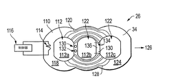
図4は図3に示された炉の構成の二次元熱分析の結果を示す。図4に示された分析から分かるように、中央のチェンバー112bが動作している。中央のチェンバー112bと外側のチェンバー112a、112cとの間の比較的薄い中央壁部130は典型的に、十分な断熱を与えない。その結果として、熱の相当部分が非動作チェンバーへの損失となる。この問題は、チェンバー112の間、または炉筐体110の間に、さらに断熱材を加えることにより単に、改善される。
【0027】
炉筐体110の壁部118は、ガス発生器の動作温度の安定性を維持するために選択された適切な断熱材から作られる。
【0028】
図5に示されているように、中間壁部の断熱材のタイプは、チェンバーのものであってもよく、通路132が中間壁部内に形成され、流体またはガスの流れが形成されて、ガス状エンベロープが形成され、熱伝導性が減少し、さらに内側チェンバー112と隣のチェンバー112との間が断熱される。これに代えて、中間壁部130に形成された一連の穴(図4)に、選択された熱伝導性または熱非伝導性流体またはガスが流れ、内側壁部130と取り囲む環境の温度を加熱し、冷却し、また調整する。
【0029】
他の断熱として、所望の熱伝導性特性をもつ、異なる断熱材から中間壁部130が形成される。図4の線134のように、壁部136は、チェンバーの残部とは異なる断熱材から形成される。
【0030】
図6に示されているように、炉筐体110は、少なくとも三つの筐体部分140から形成されてもよい。各筐体部分140は少なくとも1つの内部チェンバー112を有するが、内部チェンバーはなくともよく、また二つ以上の内部チェンバーがあってもよい。筐体部分140は好適に、隣接する筐体部分140の外側面または表面142と整合するように形成された外側面142を有する。
【0031】
このような断熱技術や他の断熱技術により、一方のチェンバー122が他方のものから分離され、分離壁部130からなる熱バリヤーが形成される。
【0032】
要約するに、COGS“モジュール”はオーブンインサートまたは筐体(断熱材、加熱要素、熱交換機、空気入口、製品ガス出口を含む)内にあるいくつかのセラミック酸素発生要素または一体的マニフォルドおよび管モジュール(IMAT)からなる。各モジュールはあるレベルの電力消費で、特定の量の酸素を生成する。酸素発生システムは、ピーク酸素フロー条件、システムサイズ条件、電力消費条件に依存する複数のモジュールからなる。
【0033】
酸素発生要素にそって炉筐体をモジュール化する本発明は以下の利点を有する。
a.温度の一様性および制御:セラミック酸素発生要素を含む筐体がより大きくなり、複数のモジュラーを含み、筐体内の温度勾配は大きくなり、制御が難しくなる。いくつかの小さな筐体を含むようにすると、より正確な制御およびより一様な温度が可能となる。
b.耐故障性:オーブン要素の機能不全の場合、機能不全を含むモジュールが停止しても、他のモジュールは作動している。他のモジュールは、ひとつのモジュールの停止を補償するために、標準モードで動作することもより高い出力モードで動作することもできる。
c.低流動での改良された効率:断熱された筐体の壁部を通過する熱の伝導は電力消費の主要な点である。ピークフローの一部が必要である場合、ひとつの筐体装置に対して全システムの熱損失を減少させるために、ひとつ以上のオーブンモジュールを停止させることができる。
【0034】
本発明のモジュールを使用してシステムの効率が高くなり、熱安定性が改善され、そのことはコストを引き下げる。このような炉の設計の潜在的な欠点は次の通りである。
1. 制御の複雑さが増す。
2. システムの大きさ、重量が増す。
3. モジュラー炉が準備中、または停止しているとき、システムの応答時間が長くなる。
【0035】
上記の本発明の説明は例示であり、本発明の範囲から逸脱することなく、大きさ、形状、材料の変更が構成とともになし得ることは分かるであろう。
【図面の簡単な説明】
【0036】
【図1】図1はモジュールセラミック酸素発生器の形態をもつ電気化学的酸素発生器を利用する全酸素発生システム10を示す。
【図2】図2はオーブン、断熱材、モジュール、ヒーター、平坦な向流熱交換機、空気流ダンパーおよびファンをもつセラミック酸素発生システムの断面を略示する。
【図3】図3は本発明のオーブンチェンバーモジュールの斜視図である。
【図4】図4は等しい温度勾配線が示された図3のオーブンチェンバーモジュールの平面図である。
【図5】図5は中間壁部に形成された断熱材のためのチェンバーをもつ本発明の他の実施例の平面図である。
【図6】図6は少なくとも三つの筐体部分をもつモジュールの他の斜視図である。【Technical field】
[0001]
This application is based on US Provisional Application No. 60 / 319,507 entitled “Modular Ceramic Oxygen System”.
[0002]
The present invention relates to the field of gas separation devices. In particular, the apparatus uses an electrochemical process that separates a gas (eg, oxygen) from a gas mixture (eg, air).
[Background]
[0003]
In one embodiment of the gas generation system, a solid state process is used for medical purposes to separate oxygen from the atmosphere. Such an apparatus is referred to as a ceramic oxygen generation system, or COGS. The ceramic electrolyte used in the oxygen separation process must be maintained at a temperature of about 600 ° C. so that the ion transport mechanism operates efficiently. Furthermore, a uniform distribution of the separation furnace temperature is necessary for proper and efficient operation.
DISCLOSURE OF THE INVENTION
[Problems to be solved by the invention]
[0004]
Significant problems arise when the product flow rate from the system is reduced. At some operating temperature, the heat dissipated by the separation module is approximately proportional to the square of the product flow rate, but the conducted heat lost through the furnace is essentially constant. An efficiently designed system is heat balanced so that the heat dissipated by the module is slightly lower than is necessary to maintain the desired furnace temperature.
[0005]
As the product flow rate decreases, the heat entering the system decreases rapidly due to the isolated modular. Since the heat loss through the furnace wall does not change, supplemental heat (provided by the preheater) is required to maintain the furnace at the desired operating temperature. The input of this preheater has no functional value except for maintaining the temperature, most of which is unrecoverable loss and other losses that propagate through the furnace walls. In short, one of the furnace enclosure with appropriate size for one product flow rate when the flow rate is decreased, excessive heat, will have a heat loss.
[0006]
Furthermore, in large furnaces, if the input to the module is reduced and the input to the auxiliary heater is increased, the furnace temperature uniformity is adversely affected. This is due in part to the different surface properties and geometric form factors between the isolated module and the preheater. The degradation in performance and system life results from the lack of temperature uniformity.
[0007]
The above prior art has many valuable advantages and technical improvements, but does not meet the objectives achieved by the present invention.
[0008]
In accordance with the present invention, the heating element, heat exchanger, an oxygen generating module, an air inlet, and products Rokatamitai for type of oxygen generation system including a gas outlet, it consists of a furnace housing member having a plurality of internal chambers. The internal chamber holds at least one oxygen generation module. Each internal chamber having an opening formed on the outer surface of the furnace housing member. Opening is uniformly separated along the central axis of the surface of the furnace housing member.
[0009]
The furnace enclosure member includes an embedded heater that provides a uniform heat distribution to the inner chamber.
[0010]
These and other objects of the present invention will become apparent from the following description with reference to the accompanying drawings, which illustrate preferred embodiments of the present invention.
BEST MODE FOR CARRYING OUT THE INVENTION
[0011]
The above-described summary of the present invention will be understood from the embodiments shown in the drawings and the following description. The above features will become apparent and better understood through the drawings. The drawings do not show only typical preferred embodiments of the invention, but allow an understanding of other equivalent embodiments of the invention.
[0012]
The above features, advantages, objects, and means of the present invention will be better understood with reference to the embodiments illustrated in the accompanying drawings. In the drawings, the same symbols are attached to the same elements.
[0013]
Patent Document 1 (US patent issued on November 16, 1999), Patent Document 2 (US patent issued on February 16, 1999), Patent Document 3 (US patent issued on February 27, 2001) (These patents are assigned to the present applicant, but are incorporated herein by reference) How are electrochemical oxygen generators made and not only generate oxygen, but over 2000 psig It describes what can be used to convey oxygen gas with pressure. As used herein, the terms “left” and “right” are relative in meaning, and the present invention can be used in any direction.
[Patent Document 1]
US Pat. No. 5,985,113 [Patent Document 2]
US Pat. No. 5,871,624 [Patent Document 3]
US Pat. No. 6,194,335 Specification [0014]
FIG. 1 is a schematic diagram of a complete
[0015]
The temperature range of the
[0016]
Oxygen is also provided to a
[0017]
FIG. 2 shows a cross section of a ceramic oxygen generation system depicting the
[0018]
Cold and fresh air is heated until it enters the inner oven, and the warm air is cooled before it leaves the
[0019]
Electrical resistance is inherent in electrochemical oxygen generation systems that use electrical potential energy rather than chemical potential energy as the driving force. The electrochemical
[0020]
As shown in FIG. 2, six
[0021]
Modular oven chamber The basic concept of the present invention improves the efficiency of the overall system by employing several small section furnaces instead of one large one. They are optimized thermally (in terms of heat loss and heat uniformity) so that small modular furnaces operate at a very narrow range of product flow rates. When demand decreases, the individual
[0022]
Similar to FIG. 2, an
[0023]
Heating element, heat exchanger, an
[0024]
Gas generating elements such as
[0025]
One feature that saves the power of this module configuration is that the insulation between the
[0026]
FIG. 4 shows the results of two-dimensional thermal analysis of the furnace configuration shown in FIG. As can be seen from the analysis shown in FIG. 4, the
[0027]
Walls of the
[0028]
As shown in FIG. 5, the type of insulation of the intermediate wall may be that of the chamber, a
[0029]
As another thermal insulation, the
[0030]
As shown in FIG. 6, the
[0031]
By such heat insulation technology or other heat insulation technology, one
[0032]
To summarize, COGS "module" in the oven insert or the housing (insulation, heating elements, heat exchanger, air inlet, comprising a product gas outlet) several ceramic oxygen generating element or integrally manifold and tube module within (IMAT). Each module produces a specific amount of oxygen with a certain level of power consumption. The oxygen generation system consists of a plurality of modules that depend on peak oxygen flow conditions, system size conditions, and power consumption conditions.
[0033]
The present invention of modularizing the furnace casing along the oxygen generating element has the following advantages.
a. Uniformity and control of the temperature: the housing Gayori increases comprising a ceramic oxygen generating element comprises a plurality of modular, temperature gradients in the casing is increased, control is difficult. Inclusion of several small enclosures allows for more precise control and more uniform temperature.
b. Fault tolerance: In the case of a malfunction of the oven element, if the module containing the malfunction stops, the other modules are still working. Other modules can operate in standard mode or in higher power modes to compensate for the stopping of one module.
c. Improved efficiency at low flow: The conduction of heat through the walls of an insulated housing is a major point of power consumption. If a portion of the peak flow is required, one or more oven modules can be shut down to reduce the overall system heat loss for a single housing device.
[0034]
Using the module of the present invention increases the efficiency of the system and improves thermal stability, which lowers costs. Potential disadvantages of such a furnace design are as follows.
1. Increased control complexity.
2. Increased system size and weight.
3. System response time is increased when the modular furnace is being prepared or stopped.
[0035]
It will be appreciated that the above description of the invention is exemplary and that changes in size, shape, and material can be made with the configuration without departing from the scope of the invention.
[Brief description of the drawings]
[0036]
FIG. 1 shows a total
FIG. 2 schematically illustrates a cross section of a ceramic oxygen generation system having an oven, insulation, module, heater, flat counter-current heat exchanger, air flow damper and fan.
FIG. 3 is a perspective view of the oven chamber module of the present invention.
FIG. 4 is a plan view of the oven chamber module of FIG. 3 showing equal temperature gradient lines.
FIG. 5 is a plan view of another embodiment of the present invention having a chamber for thermal insulation formed on the intermediate wall.
Figure 6 is another perspective view of the module with at least three housing portions.
Claims (9)
少なくともひとつの酸素発生モジュールをそれぞれが保持する、複数の内部チェンバーを有する炉筐体部材から成り、
炉筐体部材の内部チェンバー内に保持された酸素発生モジュールは加熱要素により加熱され、
内部チェンバー内に保持された酸素発生モジュールに空気が流入され、製品ガスが流出する、
ことを特徴とする炉筐体。A furnace housing for an oxygen generation system of the type including a heating element, a heat exchanger, an oxygen generation module, an air inlet, and a product gas outlet,
Each hold at least one oxygen generator module consists furnace housing member having a plurality of internal chambers,
The oxygen generation module held in the internal chamber of the furnace housing member is heated by the heating element,
Air flows into the oxygen generation module held in the internal chamber, and product gas flows out.
A furnace case characterized by that .
Applications Claiming Priority (3)
| Application Number | Priority Date | Filing Date | Title |
|---|---|---|---|
| US31950702P | 2002-08-28 | 2002-08-28 | |
| US10/604,117 US6783646B2 (en) | 2002-08-28 | 2003-06-26 | Modular ceramic oxygen system |
| PCT/US2003/025823 WO2004020063A2 (en) | 2002-08-28 | 2003-08-15 | Modular ceramic oxygen system |
Publications (3)
| Publication Number | Publication Date |
|---|---|
| JP2005537126A JP2005537126A (en) | 2005-12-08 |
| JP2005537126A5 JP2005537126A5 (en) | 2010-08-26 |
| JP4585313B2 true JP4585313B2 (en) | 2010-11-24 |
Family
ID=31981086
Family Applications (1)
| Application Number | Title | Priority Date | Filing Date |
|---|---|---|---|
| JP2004532907A Expired - Lifetime JP4585313B2 (en) | 2002-08-28 | 2003-08-15 | Modular ceramic oxygen system |
Country Status (7)
| Country | Link |
|---|---|
| US (1) | US6783646B2 (en) |
| EP (1) | EP1539317B1 (en) |
| JP (1) | JP4585313B2 (en) |
| AT (1) | ATE507324T1 (en) |
| AU (1) | AU2003263894A1 (en) |
| DE (1) | DE60336913D1 (en) |
| WO (1) | WO2004020063A2 (en) |
Families Citing this family (26)
| Publication number | Priority date | Publication date | Assignee | Title |
|---|---|---|---|---|
| US7694674B2 (en) * | 2004-09-21 | 2010-04-13 | Carleton Life Support Systems, Inc. | Oxygen generator with storage and conservation modes |
| US7396442B2 (en) | 2005-02-08 | 2008-07-08 | Carleton Life Support Systems, Inc. | Electrochemical oxygen generator module assembly |
| ES2317175T3 (en) * | 2005-11-24 | 2009-04-16 | L'air Liquide, Societe Anonyme Pour L'etude Et L'exploitation Des Procedes Georges Claude | PROCEDURE FOR PRODUCTION OF OXYGEN, FROM AIR, IN PARTICULAR THROUGH AN ELECTROCHEMICAL CELL WITH CERAMIC MEMBRANE, WITH CONTROL MEANS THAT ALLOW A CONTINUOUS PRODUCTION. |
| US7309847B2 (en) * | 2006-01-12 | 2007-12-18 | Carleton Life Support Systems, Inc. | Ceramic oxygen generating oven |
| US8323378B2 (en) * | 2010-04-28 | 2012-12-04 | Praxair Technology, Inc. | Oxygen supply method and apparatus |
| US9561476B2 (en) | 2010-12-15 | 2017-02-07 | Praxair Technology, Inc. | Catalyst containing oxygen transport membrane |
| WO2013089895A1 (en) | 2011-12-15 | 2013-06-20 | Praxair Technology, Inc. | Composite oxygen transport membrane |
| US9486735B2 (en) | 2011-12-15 | 2016-11-08 | Praxair Technology, Inc. | Composite oxygen transport membrane |
| EP2935155B1 (en) | 2012-12-19 | 2019-02-13 | Praxair Technology Inc. | Method for sealing an oxygen transport membrane assembly |
| US9453644B2 (en) | 2012-12-28 | 2016-09-27 | Praxair Technology, Inc. | Oxygen transport membrane based advanced power cycle with low pressure synthesis gas slip stream |
| US9938145B2 (en) | 2013-04-26 | 2018-04-10 | Praxair Technology, Inc. | Method and system for adjusting synthesis gas module in an oxygen transport membrane based reforming system |
| US9212113B2 (en) | 2013-04-26 | 2015-12-15 | Praxair Technology, Inc. | Method and system for producing a synthesis gas using an oxygen transport membrane based reforming system with secondary reforming and auxiliary heat source |
| US9611144B2 (en) | 2013-04-26 | 2017-04-04 | Praxair Technology, Inc. | Method and system for producing a synthesis gas in an oxygen transport membrane based reforming system that is free of metal dusting corrosion |
| US9296671B2 (en) | 2013-04-26 | 2016-03-29 | Praxair Technology, Inc. | Method and system for producing methanol using an integrated oxygen transport membrane based reforming system |
| WO2015054228A2 (en) | 2013-10-07 | 2015-04-16 | Praxair Technology, Inc. | Ceramic oxygen transport membrane array reactor and reforming method |
| US9573094B2 (en) | 2013-10-08 | 2017-02-21 | Praxair Technology, Inc. | System and method for temperature control in an oxygen transport membrane based reactor |
| CA2926757C (en) | 2013-12-02 | 2020-02-25 | Praxair Technology, Inc. | Method and system for producing hydrogen using an oxygen transport membrane based reforming system with secondary reforming |
| US9562472B2 (en) | 2014-02-12 | 2017-02-07 | Praxair Technology, Inc. | Oxygen transport membrane reactor based method and system for generating electric power |
| US10822234B2 (en) | 2014-04-16 | 2020-11-03 | Praxair Technology, Inc. | Method and system for oxygen transport membrane enhanced integrated gasifier combined cycle (IGCC) |
| US9797054B2 (en) | 2014-07-09 | 2017-10-24 | Carleton Life Support Systems Inc. | Pressure driven ceramic oxygen generation system with integrated manifold and tubes |
| US9789445B2 (en) | 2014-10-07 | 2017-10-17 | Praxair Technology, Inc. | Composite oxygen ion transport membrane |
| US10441922B2 (en) | 2015-06-29 | 2019-10-15 | Praxair Technology, Inc. | Dual function composite oxygen transport membrane |
| US10118823B2 (en) | 2015-12-15 | 2018-11-06 | Praxair Technology, Inc. | Method of thermally-stabilizing an oxygen transport membrane-based reforming system |
| US9938146B2 (en) | 2015-12-28 | 2018-04-10 | Praxair Technology, Inc. | High aspect ratio catalytic reactor and catalyst inserts therefor |
| CA3019320A1 (en) | 2016-04-01 | 2017-10-05 | Praxair Technology, Inc. | Catalyst-containing oxygen transport membrane |
| US11136238B2 (en) | 2018-05-21 | 2021-10-05 | Praxair Technology, Inc. | OTM syngas panel with gas heated reformer |
Family Cites Families (22)
| Publication number | Priority date | Publication date | Assignee | Title |
|---|---|---|---|---|
| US2839286A (en) * | 1954-06-23 | 1958-06-17 | Clarence G Poth | Checker construction for open hearth furnaces |
| US3638930A (en) * | 1970-04-24 | 1972-02-01 | Sylvania Electric Prod | Refractory metal boat for heat treating coils |
| US4378045A (en) * | 1978-10-19 | 1983-03-29 | Davy Inc. | Interlocking checker tile and supporting means for regenerative heating stoves |
| US4364798A (en) * | 1980-12-30 | 1982-12-21 | Bmi, Inc. | Rebuilt coke oven heating chamber and method of making the same |
| IN154973B (en) * | 1981-04-09 | 1984-12-22 | Otto & Co Gmbh Dr C | |
| DE3119973C2 (en) * | 1981-05-20 | 1983-11-03 | Carl Still Gmbh & Co Kg, 4350 Recklinghausen | Heating device for regenerative coking furnace batteries |
| US5378345A (en) | 1986-07-25 | 1995-01-03 | Ceramatec, Inc. | Ceramic solid electrolyte-based electrochemical oxygen concentrator cell |
| US4898792A (en) * | 1988-12-07 | 1990-02-06 | Westinghouse Electric Corp. | Electrochemical generator apparatus containing modified high temperature insulation and coated surfaces for use with hydrocarbon fuels |
| US5498487A (en) * | 1994-08-11 | 1996-03-12 | Westinghouse Electric Corporation | Oxygen sensor for monitoring gas mixtures containing hydrocarbons |
| RO114914B1 (en) * | 1995-05-09 | 1999-08-30 | Doru Tatar | Brick for heat exchangers |
| CA2182069C (en) | 1995-08-24 | 2002-04-09 | Victor P. Crome | Modular ceramic oxygen generator |
| US5985113A (en) | 1995-08-24 | 1999-11-16 | Litton Systems, Inc. | Modular ceramic electrochemical apparatus and method of manufacture therefor |
| GB9520554D0 (en) | 1995-10-07 | 1995-12-13 | Normalair Garrett Ltd | Oxygen generating device |
| US5972182A (en) | 1997-12-05 | 1999-10-26 | Ceramphysics, Inc. | Electrode composition and application method for oxygen generators |
| US6033457A (en) * | 1998-03-23 | 2000-03-07 | Oxynet, Inc. | Oxygen generator system and method of operating the same |
| GB9808133D0 (en) | 1998-04-18 | 1998-06-17 | Normalair Garrett Ltd | Ionic conduction device |
| US6290757B1 (en) | 1999-03-26 | 2001-09-18 | Ceramphysics, Inc. | Nitrogen purification device |
| FR2792210B1 (en) * | 1999-04-13 | 2001-09-14 | Air Liquide Sante Int | PORTABLE MEDICAL EQUIPMENT FOR OXYGEN THERAPY AT HOME |
| US6352624B1 (en) | 1999-06-01 | 2002-03-05 | Northrop Grumman Corporation | Electrochemical oxygen generating system |
| US6291089B1 (en) * | 1999-10-26 | 2001-09-18 | Alliedsignal Inc. | Radial planar fuel cell stack construction for solid electrolytes |
| US6382958B1 (en) | 2000-07-12 | 2002-05-07 | Praxair Technology, Inc. | Air separation method and system for producing oxygen to support combustion in a heat consuming device |
| US6379831B1 (en) * | 2000-08-02 | 2002-04-30 | Siemens Westinghouse Power Corporation | Expanded nickel screen electrical connection supports for solid oxide fuel cells |
-
2003
- 2003-06-26 US US10/604,117 patent/US6783646B2/en not_active Expired - Lifetime
- 2003-08-15 DE DE60336913T patent/DE60336913D1/en not_active Expired - Lifetime
- 2003-08-15 WO PCT/US2003/025823 patent/WO2004020063A2/en active Application Filing
- 2003-08-15 AU AU2003263894A patent/AU2003263894A1/en not_active Abandoned
- 2003-08-15 AT AT03791688T patent/ATE507324T1/en not_active IP Right Cessation
- 2003-08-15 JP JP2004532907A patent/JP4585313B2/en not_active Expired - Lifetime
- 2003-08-15 EP EP03791688A patent/EP1539317B1/en not_active Expired - Lifetime
Also Published As
| Publication number | Publication date |
|---|---|
| AU2003263894A1 (en) | 2004-03-19 |
| DE60336913D1 (en) | 2011-06-09 |
| JP2005537126A (en) | 2005-12-08 |
| WO2004020063A3 (en) | 2004-05-13 |
| EP1539317A4 (en) | 2008-02-20 |
| EP1539317B1 (en) | 2011-04-27 |
| US6783646B2 (en) | 2004-08-31 |
| EP1539317A2 (en) | 2005-06-15 |
| ATE507324T1 (en) | 2011-05-15 |
| AU2003263894A8 (en) | 2004-03-19 |
| WO2004020063A2 (en) | 2004-03-11 |
| US20040042944A1 (en) | 2004-03-04 |
Similar Documents
| Publication | Publication Date | Title |
|---|---|---|
| JP4585313B2 (en) | Modular ceramic oxygen system | |
| JP4917551B2 (en) | Electrochemical oxygen generator module assembly | |
| KR100721785B1 (en) | Electrochemical oxygen generating system | |
| US5338622A (en) | Thermal control apparatus | |
| JP2005537126A5 (en) | ||
| US20060120703A1 (en) | Fluid heater and evaluation equipment incorporating the same | |
| US20090317694A1 (en) | Temperature controller | |
| KR20170056012A (en) | Thermal management of fuel cell units and systems | |
| US7374834B2 (en) | Gas flow panels integrated with solid oxide fuel cell stacks | |
| JP2009193808A (en) | Solid oxide fuel cell | |
| AU2020319665B2 (en) | Heat storage device, heat storage system and method for operating a heat storage device | |
| KR101307870B1 (en) | Efficiency test device for fuel cell | |
| US20100047632A1 (en) | Test bench and testing method for a fuel cell stack | |
| KR101307872B1 (en) | Efficiency test device for fuel cell | |
| US3719456A (en) | Reaction chamber heated device for oxygen generation | |
| CN117346576A (en) | Heat storage device for balancing heat transfer | |
| Ueno et al. | Membrane for hydrogen and methanol fuel cells | |
| JPH01292758A (en) | Cooling device for fuel cell |
Legal Events
| Date | Code | Title | Description |
|---|---|---|---|
| A621 | Written request for application examination |
Free format text: JAPANESE INTERMEDIATE CODE: A621 Effective date: 20060623 |
|
| RD04 | Notification of resignation of power of attorney |
Free format text: JAPANESE INTERMEDIATE CODE: A7424 Effective date: 20080523 |
|
| A131 | Notification of reasons for refusal |
Free format text: JAPANESE INTERMEDIATE CODE: A131 Effective date: 20090811 |
|
| A521 | Request for written amendment filed |
Free format text: JAPANESE INTERMEDIATE CODE: A523 Effective date: 20091021 |
|
| A131 | Notification of reasons for refusal |
Free format text: JAPANESE INTERMEDIATE CODE: A131 Effective date: 20100512 |
|
| A521 | Request for written amendment filed |
Free format text: JAPANESE INTERMEDIATE CODE: A523 Effective date: 20100708 |
|
| A524 | Written submission of copy of amendment under article 19 pct |
Free format text: JAPANESE INTERMEDIATE CODE: A524 Effective date: 20100708 |
|
| A131 | Notification of reasons for refusal |
Free format text: JAPANESE INTERMEDIATE CODE: A131 Effective date: 20100803 |
|
| A521 | Request for written amendment filed |
Free format text: JAPANESE INTERMEDIATE CODE: A523 Effective date: 20100804 |
|
| TRDD | Decision of grant or rejection written | ||
| A01 | Written decision to grant a patent or to grant a registration (utility model) |
Free format text: JAPANESE INTERMEDIATE CODE: A01 Effective date: 20100825 |
|
| A01 | Written decision to grant a patent or to grant a registration (utility model) |
Free format text: JAPANESE INTERMEDIATE CODE: A01 |
|
| A61 | First payment of annual fees (during grant procedure) |
Free format text: JAPANESE INTERMEDIATE CODE: A61 Effective date: 20100903 |
|
| R150 | Certificate of patent or registration of utility model |
Ref document number: 4585313 Country of ref document: JP Free format text: JAPANESE INTERMEDIATE CODE: R150 Free format text: JAPANESE INTERMEDIATE CODE: R150 |
|
| FPAY | Renewal fee payment (event date is renewal date of database) |
Free format text: PAYMENT UNTIL: 20130910 Year of fee payment: 3 |
|
| R250 | Receipt of annual fees |
Free format text: JAPANESE INTERMEDIATE CODE: R250 |
|
| R250 | Receipt of annual fees |
Free format text: JAPANESE INTERMEDIATE CODE: R250 |
|
| R250 | Receipt of annual fees |
Free format text: JAPANESE INTERMEDIATE CODE: R250 |
|
| R250 | Receipt of annual fees |
Free format text: JAPANESE INTERMEDIATE CODE: R250 |
|
| R250 | Receipt of annual fees |
Free format text: JAPANESE INTERMEDIATE CODE: R250 |
|
| R250 | Receipt of annual fees |
Free format text: JAPANESE INTERMEDIATE CODE: R250 |
|
| R250 | Receipt of annual fees |
Free format text: JAPANESE INTERMEDIATE CODE: R250 |
|
| S531 | Written request for registration of change of domicile |
Free format text: JAPANESE INTERMEDIATE CODE: R313531 |
|
| S533 | Written request for registration of change of name |
Free format text: JAPANESE INTERMEDIATE CODE: R313533 |
|
| R350 | Written notification of registration of transfer |
Free format text: JAPANESE INTERMEDIATE CODE: R350 |
|
| R250 | Receipt of annual fees |
Free format text: JAPANESE INTERMEDIATE CODE: R250 |
|
| R250 | Receipt of annual fees |
Free format text: JAPANESE INTERMEDIATE CODE: R250 |
|
| R250 | Receipt of annual fees |
Free format text: JAPANESE INTERMEDIATE CODE: R250 |
|
| EXPY | Cancellation because of completion of term |