JP4584938B2 - Retroreflective elements and articles - Google Patents
Retroreflective elements and articles Download PDFInfo
- Publication number
- JP4584938B2 JP4584938B2 JP2006551158A JP2006551158A JP4584938B2 JP 4584938 B2 JP4584938 B2 JP 4584938B2 JP 2006551158 A JP2006551158 A JP 2006551158A JP 2006551158 A JP2006551158 A JP 2006551158A JP 4584938 B2 JP4584938 B2 JP 4584938B2
- Authority
- JP
- Japan
- Prior art keywords
- retroreflective
- sheet
- elements
- film
- layer
- Prior art date
- Legal status (The legal status is an assumption and is not a legal conclusion. Google has not performed a legal analysis and makes no representation as to the accuracy of the status listed.)
- Expired - Fee Related
Links
Images


Classifications
-
- E—FIXED CONSTRUCTIONS
- E01—CONSTRUCTION OF ROADS, RAILWAYS, OR BRIDGES
- E01F—ADDITIONAL WORK, SUCH AS EQUIPPING ROADS OR THE CONSTRUCTION OF PLATFORMS, HELICOPTER LANDING STAGES, SIGNS, SNOW FENCES, OR THE LIKE
- E01F9/00—Arrangement of road signs or traffic signals; Arrangements for enforcing caution
- E01F9/50—Road surface markings; Kerbs or road edgings, specially adapted for alerting road users
- E01F9/506—Road surface markings; Kerbs or road edgings, specially adapted for alerting road users characterised by the road surface marking material, e.g. comprising additives for improving friction or reflectivity; Methods of forming, installing or applying markings in, on or to road surfaces
- E01F9/524—Reflecting elements specially adapted for incorporation in or application to road surface markings
-
- B—PERFORMING OPERATIONS; TRANSPORTING
- B29—WORKING OF PLASTICS; WORKING OF SUBSTANCES IN A PLASTIC STATE IN GENERAL
- B29D—PRODUCING PARTICULAR ARTICLES FROM PLASTICS OR FROM SUBSTANCES IN A PLASTIC STATE
- B29D11/00—Producing optical elements, e.g. lenses or prisms
- B29D11/00605—Production of reflex reflectors
-
- G—PHYSICS
- G02—OPTICS
- G02B—OPTICAL ELEMENTS, SYSTEMS OR APPARATUS
- G02B5/00—Optical elements other than lenses
- G02B5/12—Reflex reflectors
- G02B5/136—Reflex reflectors plural reflecting elements forming part of a unitary body
-
- Y—GENERAL TAGGING OF NEW TECHNOLOGICAL DEVELOPMENTS; GENERAL TAGGING OF CROSS-SECTIONAL TECHNOLOGIES SPANNING OVER SEVERAL SECTIONS OF THE IPC; TECHNICAL SUBJECTS COVERED BY FORMER USPC CROSS-REFERENCE ART COLLECTIONS [XRACs] AND DIGESTS
- Y10—TECHNICAL SUBJECTS COVERED BY FORMER USPC
- Y10S—TECHNICAL SUBJECTS COVERED BY FORMER USPC CROSS-REFERENCE ART COLLECTIONS [XRACs] AND DIGESTS
- Y10S359/00—Optical: systems and elements
- Y10S359/90—Methods
Landscapes
- Engineering & Computer Science (AREA)
- Physics & Mathematics (AREA)
- General Physics & Mathematics (AREA)
- Ophthalmology & Optometry (AREA)
- Mechanical Engineering (AREA)
- Manufacturing & Machinery (AREA)
- Health & Medical Sciences (AREA)
- Optics & Photonics (AREA)
- Architecture (AREA)
- Civil Engineering (AREA)
- Structural Engineering (AREA)
- Optical Elements Other Than Lenses (AREA)
- Road Signs Or Road Markings (AREA)
- Laminated Bodies (AREA)
- Illuminated Signs And Luminous Advertising (AREA)
Description
本発明は、再帰反射要素、再帰反射要素を含む舗道マーキングおよび再帰反射シートのような再帰反射物品、再帰反射要素の製造方法、ラミネート、ならびにかかる再帰反射物品の使用方法に関する。 The present invention relates to retroreflective elements, retroreflective articles such as pavement markings and retroreflective sheets comprising retroreflective elements, methods of manufacturing retroreflective elements, laminates, and methods of using such retroreflective articles.
道路に沿って移動するドライバーを誘導し、指示するために舗道マーキングを用いることは周知である。舗道マーキングは、ドライバーが夜間にマーキングを見ることができるよう一般的に再帰反射性である。再帰反射性とは、表面に入射した光が反射して、入射ビームの大半が、その源へ向かって戻る機構のことである。一般的な再帰反射舗道マーキングは、顔料塗料に部分的に埋め込まれたガラスまたはガラス−セラミック微小球を含む。舗道マーキングの表面が濡れると、微小球は水でコートされ、これが再帰反射性を減じる。 It is well known to use pavement markings to guide and direct drivers moving along the road. Pavement markings are generally retroreflective so that the driver can see the markings at night. Retroreflective is a mechanism by which light incident on a surface is reflected and most of the incident beam returns toward its source. Typical retroreflective pavement markings include glass or glass-ceramic microspheres partially embedded in pigment paint. When the surface of the pavement marking gets wet, the microspheres are coated with water, which reduces retroreflectivity.
様々な再帰反射要素または凝集体が舗道マーキングを用いる業界において記載されてきた。 Various retroreflective elements or aggregates have been described in the industry using pavement markings.
例えば、米国特許第3,418,896号明細書(要約書)には、上および下面が平坦で、垂直側壁に部分的に埋め込まれた複数の小さなガラス球によりカバーされた垂直側壁を有し、平坦面の幅が、要素の厚さの少なくとも2倍で、1/8〜1/2インチの厚さで、幅は1インチを超えない、反射要素が記載されている。反射要素は、特に雨のときの夜間の再帰反射性を改善するために反射マーカに組み込むことができる。要素は、溶剤フリーのホットスプレー液体バインダーに組み込むことができる。 For example, U.S. Pat. No. 3,418,896 (abstract) has a vertical sidewall that is flat on the top and bottom and covered by a plurality of small glass spheres partially embedded in the vertical sidewall. A reflective element is described wherein the width of the flat surface is at least twice the thickness of the element, 1/8 to 1/2 inch thick, and the width does not exceed 1 inch. Reflective elements can be incorporated into reflective markers to improve nighttime retroreflectivity, particularly when it is raining. The element can be incorporated into a solvent-free hot spray liquid binder.
他の例を挙げると、米国特許第5,750,191号明細書にはプロセスが記載されており、再帰反射要素が提供されている。再帰反射要素を作成するプロセスは、(a)光学要素の土台と、熱可塑性材料を含む1つ以上のコア要素とを組み合わせる工程と、(b)光学要素とコア要素の組み合わせを十分な時間にわたって、十分な温度で攪拌して、光学要素をコア要素にコートして、再帰反射要素を形成する工程とを含む。 In another example, U.S. Pat. No. 5,750,191 describes a process and provides a retroreflective element. The process of creating the retroreflective element comprises: (a) combining the base of the optical element with one or more core elements comprising a thermoplastic material; and (b) combining the optical element and core element for a sufficient amount of time. Agitating at a sufficient temperature to coat the optical element onto the core element to form a retroreflective element.
他の例を挙げると、米国特許第6,247,818号明細書には、乾燥または湿潤条件下で再帰反射性である再帰反射要素を製造する方法が教示されている。その方法は、光学要素および/または滑り防止粒子を選択した表面に配置する手段を提供する。 As another example, US Pat. No. 6,247,818 teaches a method for making a retroreflective element that is retroreflective under dry or wet conditions. The method provides a means for placing optical elements and / or anti-slip particles on selected surfaces.
様々な再帰反射要素が明らかになっているが、業界では、製造効率の改善した、かつ/または性能の改善した他の再帰反射要素が有利であることが分かっている。 While various retroreflective elements have become apparent, the industry has found that other retroreflective elements with improved manufacturing efficiency and / or improved performance are advantageous.
一実施形態において、本発明は、バインダーに部分的に埋め込まれた複数の再帰反射要素を含む舗道マーキングに関する。他の実施形態において、本発明は再帰反射要素に関する。更に他の実施形態において、本発明は、バインダーに少なくとも部分的に埋め込まれた本発明の再帰反射要素を含むサイン、テープ、交通装置および個人用安全服のような再帰反射物品に関する。 In one embodiment, the present invention relates to a pavement marking that includes a plurality of retroreflective elements partially embedded in a binder. In other embodiments, the invention relates to retroreflective elements. In yet another embodiment, the present invention relates to retroreflective articles such as signs, tapes, traffic devices and personal safety clothing comprising the retroreflective elements of the present invention at least partially embedded in a binder.
一態様において、本発明は、再帰反射シートを含む露出した外側視認層と、視認面下にある、収縮フィルム層を含む層とを有する再帰反射要素を開示している。 In one aspect, the present invention discloses a retroreflective element having an exposed outer viewing layer comprising a retroreflective sheet and a layer comprising a shrink film layer beneath the viewing surface.
他の態様において、本発明は、視認面と対向面とを有する再帰反射シートと、シートの対向面の下に配置された(例えば、結合された)収縮可能層とを含むラミネートを開示している。かかるラミネートは、本発明の再帰反射要素を形成するための中間体として有用である。 In another aspect, the present invention discloses a laminate comprising a retroreflective sheet having a viewing surface and an opposing surface and a shrinkable layer disposed (eg, bonded) below the opposing surface of the sheet. Yes. Such laminates are useful as intermediates for forming the retroreflective elements of the present invention.
他の実施形態において、本発明は再帰反射要素の製造方法に関する。 In another embodiment, the present invention relates to a method of manufacturing a retroreflective element.
他の実施形態において、本発明は、本発明の再帰反射要素の使用方法に関する。 In other embodiments, the present invention relates to methods of using the retroreflective elements of the present invention.
これらの各実施形態について、再帰反射要素の少なくとも一部の断面が、少なくとも1つのコイルの形状、または実質的に円形形状の再帰反射シートの端部を含んでいてもよい。再帰反射要素は、外径が約0.5mm〜4mmであるのが好ましい。再帰反射要素の少なくとも一部は、実質的に中実のコアを含んでいてもよい。コアは、収縮フィルム、フィラメント、ポリマー材料(例えば、フィルム)およびこれらの組み合わせを含んでいてもよい。再帰反射シートは、露出レンズまたは密閉レンズシートであってもよい。再帰反射要素およびシートは、ガラス微小球、ガラス−セラミック微小球およびキューブコーナ要素のような光学要素を含む。光学要素は、再帰反射シートの視認面のポリマー層に少なくとも部分的に埋め込まれている。光学要素層は、予め形成された再帰反射シートとして提供されるのが好ましい。 For each of these embodiments, the cross-section of at least a portion of the retroreflective element may include at least one coil shape, or the end of a substantially circular retroreflective sheet. The retroreflective element preferably has an outer diameter of about 0.5 mm to 4 mm. At least a portion of the retroreflective element may include a substantially solid core. The core may include shrink films, filaments, polymeric materials (eg, films), and combinations thereof. The retroreflective sheet may be an exposed lens or a sealed lens sheet. Retroreflective elements and sheets include optical elements such as glass microspheres, glass-ceramic microspheres and cube corner elements. The optical element is at least partially embedded in the polymer layer on the viewing surface of the retroreflective sheet. The optical element layer is preferably provided as a preformed retroreflective sheet.
本発明の再帰反射要素は、再帰反射シート、特に舗装マーキングのような様々な再帰反射製品または物品を製造するのに用いることができる。図1を参照すると、例示的な再帰反射物品100は、バインダー層150と、反射要素の少なくとも一部が表面に露出するように、バインダー表面に少なくとも部分的に埋め込まれた多数の再帰反射要素170と、を含む。
The retroreflective elements of the present invention can be used to produce a variety of retroreflective products or articles such as retroreflective sheets, particularly pavement markings. Referring to FIG. 1, an exemplary
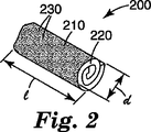
本発明の再帰反射物品(例えば、舗道マーキング)は、新規な再帰反射要素を含む。図2を参照すると、例示的な再帰反射要素200は、通常、要素330の第1の寸法(すなわち、長さ)と断面寸法220(すなわち、幅)の周囲に露出面210を有するものと定義することができる。本発明の再帰反射要素は、要素の第1の寸法(すなわち、長さ)の周囲の露出面は、光学要素230、すなわち、再帰反射シートの視認面で実質的にカバーされているという一般的な特徴を共有している。
The retroreflective article (eg, pavement marking) of the present invention includes a novel retroreflective element. With reference to FIG. 2, the exemplary
本発明の再帰反射要素は、予め形成された再帰反射シートから作成されるのが好ましい。様々な公知の再帰反射シートを用いてよい。かかる再帰反射シートは、再帰反射体のみでもよいし、トップコートと組み合わせた後にのみ再帰反射性を与えるものであってもよい。再帰反射性シートの2つの最も一般的なタイプは微小球ベースのシートおよびキューブコーナベースのシートである。通常、再帰反射シートは、ポリマー層に少なくとも部分的に埋め込まれた光学要素を含む2つの主面、すなわち、非視認面と視認面とを有する実質的に平らなものである。キューブコーナ要素およびガラスまたはガラス−セラミック微小球が最も一般的な光学要素であるが、光学要素が独立または拡散反射コアと組み合わせると光を反射するのであれば顆粒、フレーク、繊維等を用いてもよい。 The retroreflective element of the present invention is preferably made from a retroreflective sheet formed in advance. Various known retroreflective sheets may be used. Such a retroreflective sheet may be only a retroreflector, or may provide retroreflective properties only after being combined with a top coat. The two most common types of retroreflective sheets are microsphere based sheets and cube corner based sheets. Typically, the retroreflective sheet is a substantially flat surface having two major surfaces including an optical element at least partially embedded in the polymer layer, a non-viewing surface and a viewing surface. Cube corner elements and glass or glass-ceramic microspheres are the most common optical elements, but granules, flakes, fibers, etc. can be used if the optical element reflects light when combined with an independent or diffusely reflecting core. Good.
例証の再帰反射要素の断面図および/または端面図を示す図2、図3aおよび3bに図示したようなある実施形態において、再帰反射要素は、(すなわち、長手方向に沿って)それ自体に巻き付けた再帰反射シートを含む。本明細書で用いるコイルとは、間のポリマー層に埋め込まれた光学要素の連続層を有する少なくとも2つの同心円部分を有するものを言う。3bの場合には、再帰反射シートの両端(すなわち、長さに沿って)がコイル巻きされている。3cの場合には、再帰反射シートの対向端が重なっている。これらの各実施形態は、要素の内側部分が、少なくとも1層の光学要素を含むという共通の特徴を共有している。光学要素の内側層が再帰反射シートにより提供されているため、光学要素の層は、再帰反射要素の内側全体に分散ではなく離散している。従って、内側部分の内部は、光学要素のない層に近接する光学要素の離散した連続層である。本発明の再帰反射要素の外側面層(すなわち、光学要素を含む層)が摩耗のために擦り減って剥がれると、要素はもはや再帰反射性ではない。しかしながら、最終的に、コイル巻きした、または重なった光学層を有する再帰反射要素は、要素のコア内の光学要素の続く層まで擦り減ると、再び再帰反射性となる。あるいは、図3dに示すように、再帰反射シートの端部は、任意で小さなギャップを介して互いに接触する。しかしながら、それにも関わらず、本発明の再帰反射要素の視認面は、光学要素で実質的にカバーされている。 In certain embodiments, such as illustrated in FIGS. 2, 3a and 3b, showing a cross-sectional and / or end view of an exemplary retroreflective element, the retroreflective element wraps around itself (ie, along the longitudinal direction). Including retroreflective sheeting. As used herein, a coil refers to one having at least two concentric portions with a continuous layer of optical elements embedded in a polymer layer therebetween. In the case of 3b, both ends (that is, along the length) of the retroreflective sheet are coiled. In the case of 3c, the opposite ends of the retroreflective sheets overlap. Each of these embodiments share the common feature that the inner portion of the element includes at least one optical element. Since the inner layer of the optical element is provided by a retroreflective sheet, the layer of optical element is discrete rather than dispersed throughout the interior of the retroreflective element. Thus, the interior of the inner portion is a discrete continuous layer of optical elements proximate to the layer without optical elements. When the outer surface layer (ie, the layer containing the optical element) of the retroreflective element of the present invention is worn away and removed due to wear, the element is no longer retroreflective. Eventually, however, a retroreflective element having a coiled or overlaid optical layer becomes retroreflective again when worn down to a subsequent layer of optical elements in the core of the element. Alternatively, as shown in FIG. 3d, the ends of the retroreflective sheet contact each other optionally through a small gap. However, nevertheless, the viewing surface of the retroreflective element of the present invention is substantially covered by the optical element.
本発明の再帰反射物品の性能は、様々な技術により評価することができる。一般的に、舗道マーキングは、88.76度の入口角および1.05度の観測角を用いてASTM E1710、ASTM E2176−01およびASTM E2177−01に記載された通りにして、再帰反射輝度(RL)係数を求めることにより評価する。RLは、舗道マーキングを乾燥または湿潤させて求めることができる。「新しい」舗道マーキングの場合には、湿潤反射率は、石鹸水を用いて求める。石鹸を添加すると、水の表面張力が減じて、舗道マーキングの風化がシミュレートされる。舗道マーキングの表面張力は、酸化したり、擦り減る等により増加するためである。 The performance of the retroreflective article of the present invention can be evaluated by various techniques. In general, pavement markings are retroreflective luminance (as described in ASTM E1710, ASTM E2176-01 and ASTM E2177-01 using an entrance angle of 88.76 degrees and an observation angle of 1.05 degrees. R L ) is evaluated by determining the coefficient. RL can be determined by drying or wetting the pavement marking. In the case of “new” pavement markings, the wet reflectance is determined using soapy water. Adding soap reduces the surface tension of water and simulates weathering of pavement markings. This is because the surface tension of the pavement marking increases due to oxidation or abrasion.
ある好ましい実施形態において、再帰反射物品(例えば、舗道マーキング)は、匹敵するRLを示すが、全体に用いる再帰反射シートが少ないため、かなりの費用効果があると考えられる。例えば、舗道マーキングにおいて、全視認面は、再帰反射シートからなることが多い。これに対して、本発明の再帰反射要素が、1平方センチメートル当たり約1個の要素の平均占有率で提供されると、再帰反射シートの量の面積基準で僅か約14%しか用いない。 In certain preferred embodiments, retroreflective articles (e.g., pavement markings) exhibit comparable RL , but are believed to be quite cost effective due to the small number of retroreflective sheets used throughout. For example, in pavement marking, the entire viewing surface often consists of a retroreflective sheet. In contrast, when the retroreflective element of the present invention is provided with an average occupancy of about one element per square centimeter, it uses only about 14% on an area basis of the amount of retroreflective sheeting.
要素のサイズが大きい、または面積当たり複数の再帰反射要素を提供する(例えば、1平方センチメートル当たり2個以上の要素)他の実施形態については、用いた再帰反射シートの量は、視認面全体に再帰反射シートを含む物品に比べて、面積基準で20%、30%、40%、50%、60%、70%、80%、90%および更に100%以上であってもよい。 For other embodiments where the element size is large or provides multiple retroreflective elements per area (eg, two or more elements per square centimeter), the amount of retroreflective sheet used is recursive across the viewing surface. Compared to an article including a reflective sheet, it may be 20%, 30%, 40%, 50%, 60%, 70%, 80%, 90%, and even 100% or more on an area basis.
他の好ましい実施形態において、本発明の再帰反射要素は、改善された再帰反射特性、例えば、高いRL値を与える。例えば、露出レンズタイプの再帰反射シートまたは光学層を提供すると、乾燥した再帰反射性を改善することができる。ある実施形態において、乾燥時のRL値は、少なくとも2000mcd/m2/ルクス、少なくとも2500mcd/m2/ルクス、少なくとも3000mcd/m2/ルクス、および少なくとも3500mcd/m2/ルクスである。意外にも、ある実施形態において、乾燥時のRL値は、少なくとも4000mcd/m2/ルクス、少なくとも5000mcd/m2/ルクス、更に少なくとも6000mcd/m2/ルクスである。他の実施形態において、湿潤反射率(すなわち、石鹸により表面張力を減少させる)は改善され、少なくとも1500mcd/m2/ルクス、少なくとも2000mcd/m2/ルクス、少なくとも2500mcd/m2/ルクス、および少なくとも3000mcd/m2/ルクスである。最良の湿潤および乾燥再帰反射輝度は、第1の要素が乾燥再帰反射性を与え、第2の要素が湿潤再帰反射性を与える再帰反射要素の組み合わせを用いることにより得ることができる。最良の湿潤および乾燥再帰反射輝度はまた、湿潤時と乾燥時に、高いRL値の組み合わせを有する再帰反射要素を用いることにより得ることもできる。例えば、再帰反射要素は、乾燥時の前述したRL値のいずれかと組み合わせて乾燥時の前述したRL値のいずれかとを組み合わせたものを有することができる。 In other preferred embodiments, the retroreflective elements of the present invention provide improved retroreflective properties, such as high RL values. For example, providing an exposed lens type retroreflective sheet or optical layer can improve dry retroreflectivity. In certain embodiments, the R L value upon drying is at least 2000 mcd / m 2 / lux, at least 2500 mcd / m 2 / lux, at least 3000 mcd / m 2 / lux, and at least 3500 mcd / m 2 / lux. Surprisingly, in certain embodiments, the RL value upon drying is at least 4000 mcd / m 2 / lux, at least 5000 mcd / m 2 / lux, and even at least 6000 mcd / m 2 / lux. In other embodiments, wet reflectance (ie, reducing surface tension with soap) is improved, at least 1500 mcd / m 2 / lux, at least 2000 mcd / m 2 / lux, at least 2500 mcd / m 2 / lux, and at least 3000 mcd / m 2 / lux. The best wet and dry retroreflective brightness can be obtained by using a combination of retroreflective elements where the first element provides dry retroreflective and the second element provides wet retroreflective. The best wet and dry retroreflective brightness can also be obtained by using retroreflective elements that have a combination of high RL values when wet and dry. For example, the retroreflective elements may have a combination and either R L value foregoing during drying in combination with any of the aforementioned R L value at the time of drying.
再帰反射要素は、様々な好適な方法により簡単に作成することができ、少なくともいくつかを連続処理のために修正することができる。 Retroreflective elements can be easily created by various suitable methods, at least some of which can be modified for continuous processing.
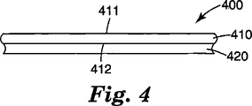
本発明の再帰反射要素を製造する一つの方法は、(a)(i)視認面411と対向(すなわち、非視認)面412とを有する再帰反射シート410と、(ii)シートの非視認面に配置された収縮可能層420とを含む図4のラミネート400を提供し、(b)フィルム層を収縮することを含む。これは一般的に、再帰反射シートの非視認面を収縮可能フィルム層に取り付ける(永久的に)ことによりなされる。あるいは、再帰反射シートは、収縮可能フィルム層で製造可能である。収縮可能フィルム層を、シート全体または再帰反射シートのロール全体に取り付けてから、ラミネートを所望のサイズに切断するのが便利である。例えば、シートは、複数のストリップに切断することができ、ストリップの幅は、再帰反射要素(すなわち、収縮後)の最終的な周縁またはコイル巻きした断面(すなわち、幅)に対応している。ストリップの長さは、再帰反射要素の長さに対応していてもよい。しかしながら、あるいは、ストリップの長さは、1つ以上(すなわち、連続した)コイルまたは管形ストランドが形成されるようかなり長いものであってもよく、これは後に離散した再帰反射要素へと切断される。
One method of manufacturing the retroreflective element of the present invention includes: (a) (i) a
一般的に、収縮可能フィルムは、単一の方向に収縮する。収縮方向に垂直なシートの端部は一般的に互いに丸まって、図2および図3a〜3dに示すように円形断面か、コイル巻された断面を形成する。 Generally, a shrinkable film shrinks in a single direction. The ends of the sheet perpendicular to the shrinking direction are generally rounded together to form a circular or coiled cross section as shown in FIGS. 2 and 3a-3d.
あるいは、2方向以上に収縮するフィルムもまた好適に用いられる。この態様について、再帰反射収縮ラミネートは、収縮前に、一般的に所望の寸法(すなわち、長さ、幅および形状)の片へと切断される。 Alternatively, a film that shrinks in two or more directions is also preferably used. For this embodiment, the retroreflective shrink laminate is generally cut into pieces of the desired dimensions (ie length, width and shape) before shrinking.
全片が実質的に同じサイズおよび形状となるように、再帰反射シートを片へと切断また打ち抜いてもよい。あるいは、シートは、様々な異なるサイズおよび形状を与える不規則なやり方で切断してもよい。収縮可能フィルム層の指向性収縮成分と組み合わせて再帰反射シート片の初期形状に応じて、得られる再帰反射要素は、様々な規則および不規則形状を有することができる。例えば、再帰反射要素は、実質的に円柱形および枕、立方体等の形状であってもよい。 The retroreflective sheet may be cut or punched into pieces so that all pieces are substantially the same size and shape. Alternatively, the sheet may be cut in an irregular manner giving a variety of different sizes and shapes. Depending on the initial shape of the retroreflective sheeting piece in combination with the directional shrinkage component of the shrinkable film layer, the resulting retroreflective element can have various regular and irregular shapes. For example, the retroreflective elements may be substantially cylindrical and in the shape of pillows, cubes, and the like.
様々な収縮可能フィルム材料が知られている。ここで用いる「収縮可能フィルム」および「収縮可能層」とは、弾性記憶を有するために少なくとも1つの方向に減少可能なポリマー組成物のことを指す。主に、2つのタイプの収縮可能フィルムがある。第1のタイプは、周囲温度でエラストマーであるポリマーフィルムである。かかるフィルムは、機械的に伸張して、再帰反射シートの非視認面に結合することができる。代表例としては、ラテックス、ゴム、ニトリルゴムおよびスチレン−イソプレン−スチレン、スチレン−ブタジエン−スチレンおよびスチレン−エチレン/ブチレン−スチレン(例えば、「クラトン(Kraton)」という商品名でシェル(Shell)より市販されているもの)のような熱可塑性エラストマーが挙げられる。 Various shrinkable film materials are known. As used herein, “shrinkable film” and “shrinkable layer” refer to a polymer composition that can be reduced in at least one direction to have elastic memory. There are mainly two types of shrinkable films. The first type is a polymer film that is an elastomer at ambient temperature. Such a film can be mechanically stretched and bonded to the non-viewing surface of the retroreflective sheet. Representative examples are latex, rubber, nitrile rubber and styrene-isoprene-styrene, styrene-butadiene-styrene and styrene-ethylene / butylene-styrene (eg, commercially available from Shell under the trade name "Kraton"). Thermoplastic elastomers such as those described above).
第2のタイプは、まずポリマー材料を所望の形状に押出す、またはその他成形することにより弾性記憶が付与されたポリマーフィルムである。ポリマーを、高エネルギー放射線、例えば、電子ビームに露光することにより架橋する、または架橋した材料の特性を与える。架橋は、紫外線に露光する、または、ポリオレフィンを用いるときは、化学的手段、例えば、過酸化物により行う。架橋したポリマー材料を、加熱および変形し(例えば、少なくとも1つの方向に伸張し)、急冷またはその他好適な冷却によりその状況、あるいはそれにかわる状況で固定する。同プロセスは、ポリマーを変形するのにより大きな力を使うことにより融点より低くして行うことができる。変形した材料は、回復させるのに十分な高温、ポリエチレンの場合には約250°Fに露出するまでほぼ無期限にその形状を維持する。かかる材料はまた、熱収縮フィルムおよび熱回復フィルムとも呼ばれる。有用な熱収縮材料は、一般的に、紫外線および酸化分解に対して安定化させてあるポリオレフィン(例えば、ポリエチレン、ポリプロピレン)、ポリエステル(例えば、ポリエチレンテレフタレート)またはポリアミド(例えば、ナイロン)、ポリウレタン、ポリ塩化ビニル、ポリフッ化ビニリデンをはじめとする半結晶架橋ポリマーから構成されるがこれらに限られるものではない。弾性記憶の特性はまた、結晶融点より高い温度でポリマーに相当の強度を与えるのに十分な高分子量を有する架橋ポリマー(例えば、ポリオレフィンおよびビニルポリマー)の特性を有する材料にも付与される。非結晶ポリマー(例えば、ネオプレン)と、半結晶ポリマー(例えば、ポリエチレン)のブレンドもまた熱収縮材料として有用である。大幅に分解することなく放射線により架橋されるポリエチレンとその他のポリマーの場合には、ウェブ処理および架橋化学を精密に制御するために電子ビーム架橋が非常に望ましい。放射線架橋材料は、線量/モジュラス応答および強化および熱導電性を増大するためのカーボンブラックの充填を促すために、任意でプロラド(pro−rad)(多官能性アクリレートまたはアリルモノマー)を含有する。かかる材料の配向は、一般的に、押出しおよび架橋工程に従い、組成物の結晶融点より高い温度で行われる。材料を伸張状態で冷却すると、配向は適所に固定される。通常、直径の変化に対応するには、直線1インチ当たり約15ポンドまでの回復力で約8までの伸張比が可能であり、伸張比および架橋密度により制御することができる。 The second type is a polymer film to which an elastic memory is imparted by first extruding a polymer material into a desired shape or by other molding. The polymer is crosslinked by exposure to high energy radiation, eg, an electron beam, or imparts the properties of a crosslinked material. Crosslinking is performed by chemical means such as peroxide when exposed to UV light or when polyolefins are used. The crosslinked polymeric material is heated and deformed (e.g., stretched in at least one direction) and secured in that situation or in a situation that may be by quenching or other suitable cooling. The process can be performed below the melting point by using greater force to deform the polymer. The deformed material maintains its shape indefinitely until exposed to a high enough temperature to recover, in the case of polyethylene to about 250 ° F. Such materials are also referred to as heat shrink films and heat recovery films. Useful heat shrink materials are generally polyolefins (eg, polyethylene, polypropylene), polyesters (eg, polyethylene terephthalate) or polyamides (eg, nylon), polyurethanes, poly, which are stabilized against UV and oxidative degradation. It is composed of a semi-crystalline crosslinked polymer such as vinyl chloride and polyvinylidene fluoride, but is not limited thereto. Elastic memory properties are also imparted to materials having the properties of crosslinked polymers (eg, polyolefins and vinyl polymers) having a high molecular weight sufficient to give the polymer considerable strength at temperatures above the crystalline melting point. Blends of amorphous polymers (eg, neoprene) and semicrystalline polymers (eg, polyethylene) are also useful as heat shrink materials. In the case of polyethylene and other polymers that are cross-linked by radiation without significant degradation, electron beam cross-linking is highly desirable for precise control of web processing and cross-linking chemistry. The radiation cross-linked material optionally contains a pro-rad (polyfunctional acrylate or allyl monomer) to facilitate loading of carbon black to increase dose / modulus response and enhancement and thermal conductivity. Such material orientation is generally performed at a temperature above the crystalline melting point of the composition, following an extrusion and crosslinking process. When the material is cooled in the stretched state, the orientation is fixed in place. Typically, to accommodate diameter changes, stretch ratios of up to about 8 are possible with a recovery force of up to about 15 pounds per linear inch, and can be controlled by stretch ratio and crosslink density.
コイル巻きした、または円形断面の再帰反射要素を得るには、収縮可能(例えば、フィルム)層の回復力が、再帰反射シートを含有するラミネートの曲げ強度より大きい。回復力は、弾性記憶と、収縮可能(例えば、フィルム)層の厚さの両方の関数である。収縮可能(例えば、フィルム)層は、好ましくは、ラミネートの少なくとも1つの寸法において少なくとも約5%収縮する。一般的に、収縮量は約25%までである。収縮可能フィルムの大量の回復エネルギーが吸収されるため、収縮可能(例えば、フィルム)層が、再帰反射シートに結合する前、かなり高度の収縮を単独で有するのが一般的である。例えば、非拘束(すなわち、結合前)の収縮可能フィルムは150%、200%、250%等収縮する。一般的に、結合されていない収縮可能フィルムの収縮は約500%以下である。従って、間が任意の程度収縮している収縮可能フィルム層を有用に用いることができる。より密にコイル巻きされた(例えば、実質的に固体の)再帰反射要素を得るには、低い曲げ強度の再帰反射シートと組み合わせてより高い収縮力(パーセンテージおよび厚さ)が好ましい。出願人は、トップコートの存在により、再帰反射シートの曲げ強度が増大できることを知見した。従って、かかるトップコートが存在するときは、トップコートは、ラミネートの収縮後に提供されるのが好ましい。収縮可能フィルムは一般的に連続しているものの、不連続フィルムもまた有用に用いられる。例えば、収縮可能フィルム材料またはエラストマーストランドのストリップを再帰反射シートに結合してもよい。 To obtain a coiled or circular cross-section retroreflective element, the resiliency of the shrinkable (eg, film) layer is greater than the flexural strength of the laminate containing the retroreflective sheet. The recovery force is a function of both elastic memory and the thickness of the shrinkable (eg, film) layer. The shrinkable (eg, film) layer preferably shrinks at least about 5% in at least one dimension of the laminate. Generally, the amount of shrinkage is up to about 25%. Because the large amount of recoverable energy of the shrinkable film is absorbed, it is common for the shrinkable (eg, film) layer to have a fairly high degree of shrinkage alone before bonding to the retroreflective sheet. For example, an unconstrained (ie, before bonding) shrinkable film shrinks 150%, 200%, 250%, etc. Generally, the shrinkage of unbonded shrinkable film is about 500% or less. Therefore, a shrinkable film layer that is shrunk to any degree can be used effectively. In order to obtain a more closely coiled (eg, substantially solid) retroreflective element, a higher shrinkage force (percentage and thickness) in combination with a low bending strength retroreflective sheet is preferred. The applicant has found that the bending strength of the retroreflective sheet can be increased by the presence of the top coat. Thus, when such a topcoat is present, the topcoat is preferably provided after shrinkage of the laminate. Although shrinkable films are generally continuous, discontinuous films are also usefully used. For example, a shrinkable film material or a strip of elastomeric strands may be bonded to the retroreflective sheet.
再帰反射シートまたはその片の寸法に応じて、収縮可能フィルム層は、再帰反射シートを所望の寸法(例えば、ストリップ)に切断する前か後に結合される。収縮可能フィルムは、(例えば、感圧)接着剤、ヒートラミネーション、化学グラフト、無線周波溶接、シートの非視認面への収縮可能フィルム層の押出し、収縮可能フィルム層とシートのバッキング層の共押出しおよびこれらの組み合わせによる等、任意の好適なやり方で非視認面に取り付けることができる。 Depending on the dimensions of the retroreflective sheet or piece thereof, the shrinkable film layer is bonded before or after cutting the retroreflective sheet into the desired dimensions (eg, strips). Shrinkable film can be (for example, pressure sensitive) adhesive, heat lamination, chemical grafting, radio frequency welding, extrusion of shrinkable film layer to non-viewing surface of sheet, coextrusion of shrinkable film layer and sheet backing layer And can be attached to the non-viewing surface in any suitable manner, such as by combinations thereof.
収縮可能フィルムを非視認面に取り付けるのに様々な公知の接着組成物が好適である。接着剤が、熱収縮プロセス中に大幅に流れないよう、十分に架橋される、または粘性であれば、ホットメルトおよび熱活性接着組成物を用いて、熱収縮フィルムを結合することができる。伸張したエラストマーフィルムの結合の場合には、接着剤の適用温度は、エラストマーフィルムの溶融温度より低いのが好ましい。熱収縮フィルムを再帰反射シートの非視認面に結合するのに好ましい接着組成物は、感圧接着組成物である。感圧接着剤は、通常、天然ゴム、合成ゴム、ブロックコポリマー、ポリビニルエーテル、アクリル樹脂、ポリアルファオレフィン、シリコーンおよび少なくとも1種類の粘着付与材と組み合わせたこれらの混合物のようなベースポリマーから構成される。様々な感圧接着剤は、例えば、米国特許第6,632,522号明細書に記載されている。米国特許第6,677,030号明細書および同第5,804,610号明細書に記載されているような高分子量アクリル系接着剤およびゴム(天然および合成)系接着剤は、ポリオレフィンから構成された熱収縮フィルムに対して適正な接着力を示す傾向がある。 Various known adhesive compositions are suitable for attaching the shrinkable film to the non-viewing surface. If the adhesive is sufficiently cross-linked or viscous so that it does not flow significantly during the heat shrink process, the heat shrink film can be bonded using hot melt and heat activated adhesive compositions. In the case of bonding of stretched elastomeric films, the adhesive application temperature is preferably lower than the melting temperature of the elastomeric film. A preferred adhesive composition for bonding the heat shrink film to the non-viewing surface of the retroreflective sheet is a pressure sensitive adhesive composition. Pressure sensitive adhesives are usually composed of a base polymer such as natural rubber, synthetic rubber, block copolymer, polyvinyl ether, acrylic resin, polyalphaolefin, silicone and mixtures thereof in combination with at least one tackifier. The Various pressure sensitive adhesives are described, for example, in US Pat. No. 6,632,522. High molecular weight acrylic and rubber (natural and synthetic) adhesives such as those described in US Pat. Nos. 6,677,030 and 5,804,610 are composed of polyolefins. There is a tendency to show an appropriate adhesive force to the heat-shrinkable film.
接着結合の代わりに、またはこれに加えて、熱収縮フィルムの表面は、米国特許第4,563,388号明細書に記載されているような表面コーティングを提供することにより化学的にグラフトされていてもよい。これは、熱収縮フィルムの表面の少なくとも一部を、アクリル酸、メタクリル酸およびそのエステル、アクリルアミド、メタクリルアミド、立体非障害第3級アルキルアクリルアミドおよびメタクリルアミド、アルキル基に3個以下の炭素原子を有する第2級アルキルアクリルアミドおよびメタクリルアミド、ならびにN−ビニルピロリドンからなる群より選択される少なくとも1種類のモノマーでグラフト重合することにより実施される。グラフト重合は、熱収縮フィルムの望ましい部分を、少なくとも1種類の上記のモノマーを含む組成物でコーティングし、コートした部分をイオン化放射線、例えば、電子ビーム放射線で照射することにより実施するのが好ましい。好ましいコーティングは、多量のN,N−ジメチルアクリルアミド(DMMA)、少量のポリアクリレート、例えば、トリメチロールプロパントリアクリレート(TMPTA)と、任意で微量の界面活性剤および酸または鉱物連鎖移動剤、例えば、硝酸または銀、銅等の塩を含む。コーティングは、例えば、ファインローレットグラビアコータを利用して、熱収縮フィルムに適用し、電子ビームにより薄いフィルムとして照射することができる。コーティングは、ラミネートの曲げ強度を実質的に増大せず、伸張したときに別個の部分に分解しないよう一般的に薄い(例えば、約1ミル)。エチレンメタクリル酸(EMMA)バッキング層が存在するとき等、再帰反射シートの非視認面が酸含有ポリマーを含むときは、収縮可能フィルムへのグラフト重合が特に好適である。アクリレートモノマー(例えば、DMA)の薄いコーティングと直接反応して、当該の官能基(例えば、アミン)を収縮可能フィルム面に共有結合できるイオン化エネルギー(例えば、電子ビーム)を用いてフリーラジカルを収縮可能フィルム面に生成してもよい。再帰反射シートバッキング(例えば、EMMAバッキング)の非視認面を、ラミネートを収縮させる収縮可能フィルムの通常の融点より低いが、フィルム面を良好に濡らすのに十分に高い温度で収縮可能フィルムにラミネートするとき、十分に強いイオン引力が生じて、収縮プロセス中結合を維持し、再帰反射シート面を平滑に(すなわち、接着剤のフローによりしわがない)保持する傾向も有している。 Instead of or in addition to adhesive bonding, the surface of the heat shrink film is chemically grafted by providing a surface coating as described in US Pat. No. 4,563,388. May be. This is because at least part of the surface of the heat-shrinkable film is formed by adding 3 or less carbon atoms to acrylic acid, methacrylic acid and esters thereof, acrylamide, methacrylamide, sterically unhindered tertiary alkyl acrylamide and methacrylamide, alkyl groups. It is carried out by graft polymerization with at least one monomer selected from the group consisting of secondary alkyl acrylamide and methacrylamide having N-vinyl pyrrolidone. Graft polymerization is preferably carried out by coating the desired portion of the heat shrink film with a composition comprising at least one of the above monomers and irradiating the coated portion with ionizing radiation, eg, electron beam radiation. Preferred coatings include large amounts of N, N-dimethylacrylamide (DMMA), small amounts of polyacrylates such as trimethylolpropane triacrylate (TMPTA), and optionally trace amounts of surfactants and acid or mineral chain transfer agents such as Contains salts of nitric acid or silver, copper, etc. The coating can be applied to a heat shrink film using a fine knurl gravure coater, for example, and irradiated as a thin film with an electron beam. The coating is generally thin (eg, about 1 mil) so that it does not substantially increase the flexural strength of the laminate and does not decompose into separate parts when stretched. Graft polymerization onto a shrinkable film is particularly suitable when the non-viewing surface of the retroreflective sheet contains an acid-containing polymer, such as when an ethylene methacrylic acid (EMMA) backing layer is present. Free radicals can be contracted using ionization energy (eg, electron beam) that can react directly with a thin coating of acrylate monomer (eg, DMA) to covalently bond the functional group (eg, amine) to the shrinkable film surface. You may produce | generate on a film surface. Laminate the non-viewing surface of a retroreflective sheet backing (eg, EMMA backing) to the shrinkable film at a temperature below the normal melting point of the shrinkable film that shrinks the laminate, but high enough to wet the film surface well Sometimes, a sufficiently strong ion attractive force is also generated to tend to maintain the bond during the shrinking process and keep the retroreflective sheeting surface smooth (ie, free from wrinkles due to the flow of adhesive).
公知の屋外耐久性のために好ましい接着剤としては、隆起舗道マーカおよび舗道マーキングテープに用いるのに好適なものが挙げられる。例えば、接着剤は、米国特許第5,906,889号明細書、国際公開第98/24978号パンフレットおよび米国特許出願公開第2003/0091815号明細書に記載されているような天然ゴム、ポリブタジエンまたはアクリルポリマーおよび粘着付与剤を含む。 Adhesives preferred for known outdoor durability include those suitable for use in raised pavement markers and pavement marking tapes. For example, the adhesive may be natural rubber, polybutadiene or as described in US Pat. No. 5,906,889, WO 98/24978 and US 2003/0091815. Contains acrylic polymer and tackifier.
再帰反射シートの非視認面を、静的または連続方法により、収縮可能(すなわち、フィルム)層にヒートラミネートしてもよい。ヒートラミネーションには、通常、熱、時間および圧力が係る。ある静的ヒートラミネーション方法には、再帰反射シートの非視認面と収縮可能(すなわち、フィルム)層を接触させて、加熱したプラテンプレスにてラミネートすることが含まれる。連続方法においては、フィルム層とシートを、一組の駆動ニップロールに通過させることにより合わせてラミネートする。例えば、再帰反射シートと収縮可能(すなわち、フィルム)層は、一組の鋼および/またはゴムコートニップロールに通過させてもよい。ヒートラミネーション中、結合させるためにニップロールの一方または両方を加熱することができる。ラミネーションプロセスで用いる条件は、互いにラミネートされるフィルムの種類に応じて異なる。例えば、直鎖低密度ポリエチレン(LLDPE)のような比較的低軟化点のフィルムは、一般的に、180°F〜330°Fの範囲の温度でヒートラミネートされる。ポリエチレンテレフタレート、高密度ポリエチレンおよびポリプロピレンのようなその他材料は、一般的に、約330°F以上のような高温でヒートラミネートされる。 The non-viewing surface of the retroreflective sheet may be heat laminated to the shrinkable (ie film) layer by static or continuous methods. Heat lamination usually involves heat, time and pressure. One static heat lamination method involves contacting the non-viewing surface of the retroreflective sheet with a shrinkable (ie, film) layer and laminating with a heated platen press. In a continuous process, the film layer and sheet are laminated together by passing them through a set of drive nip rolls. For example, the retroreflective sheet and the shrinkable (ie, film) layer may be passed through a set of steel and / or rubber coated nip rolls. During heat lamination, one or both of the nip rolls can be heated for bonding. The conditions used in the lamination process vary depending on the types of films that are laminated together. For example, relatively low softening point films such as linear low density polyethylene (LLDPE) are typically heat laminated at temperatures ranging from 180 ° F to 330 ° F. Other materials such as polyethylene terephthalate, high density polyethylene and polypropylene are typically heat laminated at high temperatures such as about 330 ° F. or higher.
本発明の再帰反射要素を製造する他の方法は、長手方向面を有する細長い部材を提供する工程と、細長い部材周囲に再帰反射シートを結合して、長手方向面がシートの主視認面で実質的にカバーされるようにする工程とを含む。細長い部材は、再帰反射要素の内側の一体部であるコア部材を含んでいてもよい。ポリマー材料(例えば、フィルム)、フィラメント(例えば、ポリマーまたは非ポリマー)中の好適なコア材料および押出された熱可塑性ストランド。あるいは、細長い部材はツールであってもよい。例えば、本方法では、再帰反射シートをマンドレル周囲で包んで、シートを重ねて視認面を露出し、重なり部分で少なくとも結合させることを含んでもよい。同じく考えられるのは、中空管状コア部材を提供し、管状コア部材を、ポリマーコーティングおよび光学要素でコートして、光学層が予め成形しておいた再帰反射シートとして提供されるのでなく、インラインで形成されることである。この構造は、(例えば、熱可塑性)コア材料で同時または後に充填される中間体であってもよい。 Another method of manufacturing the retroreflective element of the present invention includes providing an elongate member having a longitudinal surface and joining the retroreflective sheet around the elongate member so that the longitudinal surface is substantially the main viewing surface of the sheet. The process of ensuring that it is covered. The elongate member may include a core member that is an integral part of the interior of the retroreflective element. Suitable core material in extruded polymer material (eg film), filament (eg polymer or non-polymer) and extruded thermoplastic strands. Alternatively, the elongated member may be a tool. For example, the method may include wrapping the retroreflective sheet around the mandrel, overlapping the sheets to expose the viewing surface, and at least joining at the overlap. It is also envisaged that a hollow tubular core member is provided and the tubular core member is coated with a polymer coating and an optical element so that the optical layer is not provided as a pre-shaped retroreflective sheet, but in-line. Is to be formed. This structure may be an intermediate that is filled simultaneously (or later) with a (eg thermoplastic) core material.
再帰反射シートの非視認面は、細長いコア部材に結合してもよいし、かつ/または再起反射シートは、再帰反射シートの非視認面を収縮(すなわち、フィルム)層に結合するために前述したような任意の好適なやり方でそれ自体に結合(例えば、重なって)していてもよい。感熱材料が存在しないときは、様々なホットメルト接着剤を有用に用いることができる。コア部材を、シートの非視認面と接触させる前に、架橋性接着剤を細長いコア部材の周縁に適用するのが一般的に便利である。細長いコア部材は、再帰反射要素の断面幅より小さな直径を有している。コア部材の長さが、再帰反射要素の所望の最大寸法より大きい実施形態については、露出した表面で再帰反射シートで実質的にカバーされた(例えば、連続)細長い部材を、離散した再帰反射要素へ切断してもよい。 The non-viewing surface of the retroreflective sheet may be bonded to the elongate core member and / or the re-reflective sheet is described above for bonding the non-viewing surface of the retroreflective sheet to the shrink (ie, film) layer. It may be attached (eg, overlapped) to itself in any suitable manner. When no heat sensitive material is present, various hot melt adhesives can be usefully used. It is generally convenient to apply a crosslinkable adhesive to the periphery of the elongated core member before contacting the core member with the non-viewing surface of the sheet. The elongated core member has a diameter that is less than the cross-sectional width of the retroreflective element. For embodiments in which the length of the core member is greater than the desired maximum dimension of the retroreflective element, the elongated member substantially covered with a retroreflective sheeting (eg, continuous) on the exposed surface is replaced with a discrete retroreflective element. You may cut into
これらの各実施形態において、再帰反射シートは、非視認面に配置された追加の層を含んでいてもよい。例えば、再帰反射シートは、接着層を含んでいてもよい。かかる反射層を用いて、収縮フィルム層をシートを非視認面に結合したり、シートの非視認面を細長いコア部材に結合したり、再帰反射シートをそれ自体に結合して、重なりまたはコイルを形成してもよい。 In each of these embodiments, the retroreflective sheet may include an additional layer disposed on the non-viewing surface. For example, the retroreflective sheet may include an adhesive layer. With such a reflective layer, the shrink film layer is bonded to the non-viewing surface of the sheet, the non-viewing surface of the sheet is bonded to the elongated core member, or the retroreflective sheet is bonded to itself to overlap or coil It may be formed.
あるいは、またはこれに加えて、これらの各実施形態は、再帰反射要素のコア材料となる追加のフィルム層を含んでいてもよい。この目的に好適なフィルム材料としては、様々な熱可塑性および熱硬化性ポリマー材料およびこれらの組み合わせが挙げられる。例証の熱可塑性材料としては、例えば、未架橋エラストマー前駆体(例えば、ニトリルゴム処方)、エチレン−酢酸ビニルコポリマー、ポリエステル、ポリ酢酸ビニル、ポリウレタン、ポリウレア、アクリル樹脂、メタクリル樹脂、エチレンアクリレート/メタクリレートコポリマー、エチレン−アクリル酸/メタクリル酸コポリマー、ポリビニルブチラール等が挙げられる。例証の熱硬化性材料としては、アミノ樹脂、熱硬化性アクリル樹脂、熱硬化性メタクリル樹脂、ポリエステル樹脂、乾燥油、アルキド樹脂、エポキシおよびフェノール樹脂、イソシアネートベースのポリウレタン、イソシアネートベースのポリウレア等が例示される。 Alternatively, or in addition, each of these embodiments may include an additional film layer that becomes the core material of the retroreflective element. Suitable film materials for this purpose include various thermoplastic and thermoset polymeric materials and combinations thereof. Illustrative thermoplastic materials include, for example, uncrosslinked elastomer precursors (eg, nitrile rubber formulations), ethylene-vinyl acetate copolymers, polyesters, polyvinyl acetate, polyurethanes, polyureas, acrylic resins, methacrylic resins, ethylene acrylate / methacrylate copolymers. , Ethylene-acrylic acid / methacrylic acid copolymer, polyvinyl butyral, and the like. Illustrative thermosetting materials include amino resins, thermosetting acrylic resins, thermosetting methacrylic resins, polyester resins, drying oils, alkyd resins, epoxy and phenolic resins, isocyanate-based polyurethanes, isocyanate-based polyureas, etc. Is done.
更に、トップコートを再帰反射シートの視認面、または再帰反射要素の露出面に適用してもよい。場合によっては、かかるトップコートは、シートの光学諸特性を完成する。すなわち、シートは、トップコート適用後まで非常に低レベルの再帰反射性のみを有する。他の場合には、トップコートは、再帰反射要素の完全性を改善し、要素においてその形状を維持する補助をする。トップコートは、通常、可視光の少なくとも70%を透過する。トップコートは、好ましくは可視光の80%以上を透過する、最も好ましくは90%以上を透過するよう十分に透明である。好適なトップコートとしては、ポリウレタン、ポリエステル、アクリル樹脂、エチレンアクリル酸、エチレンメタクリル酸のような酸オレフィンコポリマー、ベース「イオノマー」で中和された酸オレフィンコポリマー、ポリ塩化ビニルおよびそのコポリマー、エポキシ、ポリカーボネートおよびこれらの混合物が挙げられるが、これらに限られるものではない。好ましいトップコートとしては、好ましくは架橋しておいたポリウレタンポリマー、アクリルポリマーおよびこれらのブレンドを含むコーティング組成物が挙げられる。ある例証のトップコートは、マサチューセッツ州ウィルミントンのICIレジン(ICI Resins,Wilmington,MA)より「CX−100」という商品名で市販されているアジリジン架橋剤と混合された同じくICIレジン(ICI Resins)より「ネオレッズ(Neorez)R−960」という商品名で市販されている水系ウレタンである。他の例の水系アクリルトップコートは、2004年1月29日公開の米国特許出願公開第2004/0018344−A1号明細書に記載されている。安定剤、着色剤、紫外線吸収剤、酸化防止剤等のような様々な添加剤をトップコート層材料に添加すると、処理、耐候性または再帰反射色に影響を及ぼす。 Furthermore, the top coat may be applied to the viewing surface of the retroreflective sheet or the exposed surface of the retroreflective element. In some cases, such a topcoat completes the optical properties of the sheet. That is, the sheet has only a very low level of retroreflectivity until after the topcoat is applied. In other cases, the topcoat improves the integrity of the retroreflective element and helps maintain its shape in the element. The topcoat typically transmits at least 70% of visible light. The topcoat is preferably sufficiently transparent to transmit 80% or more of visible light, most preferably 90% or more. Suitable topcoats include polyurethanes, polyesters, acrylic resins, acid olefin copolymers such as ethylene acrylic acid, ethylene methacrylic acid, acid olefin copolymers neutralized with a base “ionomer”, polyvinyl chloride and copolymers thereof, epoxies, Examples include, but are not limited to, polycarbonate and mixtures thereof. Preferred topcoats include coating compositions that preferably include cross-linked polyurethane polymers, acrylic polymers and blends thereof. One illustrative topcoat is also ICI Resins mixed with an aziridine crosslinker marketed under the trade designation “CX-100” from ICI Resins, Wilmington, Mass. Further, it is a water-based urethane marketed under the trade name “Neorez R-960”. Another example water-based acrylic topcoat is described in US Patent Application Publication No. 2004 / 0018344-A1, published January 29, 2004. The addition of various additives such as stabilizers, colorants, UV absorbers, antioxidants, etc. to the topcoat layer material affects the processing, weather resistance or retroreflective color.
ハードコートを再帰反射要素に適用してその耐久性を改善してもよい。様々なハードコートが知られている。例えば、無機酸化物材料またはダイヤモンドライクカーボン材料を含む薄い連続ハードコート層が国際公開第03/091762号パンフレットに記載されている。約20%〜約80%のエチレン化不飽和モノマー、約10%〜約50%のアクリレート官能性コロイドシリカ、および約5%〜約40%の99〜500原子質量単位の分子量を有するN,N−二置換アクリルアミドまたはN−置換N−ビニル−アミドモノマーから作成された好ましい耐摩耗性クリーマー(creamer)ハードコートコーティングは、米国特許第5,677,050号明細書(ビルカディら(Bilkadi,et al.))に記載されている。 A hard coat may be applied to the retroreflective element to improve its durability. Various hard coats are known. For example, a thin continuous hard coat layer containing an inorganic oxide material or a diamond-like carbon material is described in WO 03/091762. About 20% to about 80% ethylenically unsaturated monomer, about 10% to about 50% acrylate functional colloidal silica, and about 5% to about 40% N, N having a molecular weight of 99-500 atomic mass units A preferred abrasion resistant creamer hardcoat coating made from disubstituted acrylamide or N-substituted N-vinyl-amide monomers is described in US Pat. No. 5,677,050 (Bilkadi et al. .))It is described in.
本発明の再帰反射要素を作成したやり方に関らず、ある実施形態においては、再帰反射要素の少なくとも一部が中実コアを含む。これは、例えば、シートをより密にコイル巻きする、中空(例えば、管状形)ストランドを捻る、中空要素にコア材料を充填する、またはその他手段により行える。中実コア要素は、中空再帰反射要素に比べて増大した衝撃強さを示すと考えられる。 Regardless of the manner in which the retroreflective elements of the present invention are created, in some embodiments, at least some of the retroreflective elements include a solid core. This can be done, for example, by more closely coiling the sheet, twisting hollow (eg, tubular) strands, filling the hollow element with core material, or other means. Solid core elements are believed to exhibit increased impact strength compared to hollow retroreflective elements.
本発明の再帰反射要素は、様々なコア材料で充填してもよい。好適なコア材料としては、例えば、様々なポリマー材料が挙げられる。特に、フィルム層コア材料として用いるのに前述した様々なポリマー材料を好適に用いることができる。例えば、かかる熱可塑性コア材料を、製造中、中空コイルまたは管状形ストランドの中央部に同時に押出してもよい。 The retroreflective elements of the present invention may be filled with various core materials. Suitable core materials include, for example, various polymer materials. In particular, the various polymer materials described above for use as the film layer core material can be suitably used. For example, such a thermoplastic core material may be simultaneously extruded into the center of a hollow coil or tubular strand during manufacture.
他の実施形態において、再帰反射要素は、少なくとも部分的に中空であり、キャビティを有している。キャビティは、要素の一つの断面端部から他へ連続していてもよい。あるいは、キャビティは不連続であってもよい。不連続キャビティは、より密にコイル巻きされた、または捻られた部分(例えば、要素の長さに沿って)のみに形成してもよい。更に、ホットナイフで行えるように、中間要素コイルまたはストランドを離散要素へと切断する結果、キャビティは、再帰反射要素の少なくとも1つまたは両断面端部で不連続であってもよい。少なくとも部分キャビティを要素内に提供すると、(例えば、舗道マーキングの)バインダーが要素内部で吸い取られて、単なる表面結合でなく、要素の内部層と機械的結合が形成され有利であると考えられる。これらの実施形態において、バインダーと混合する前、再帰反射要素は少なくとも部分的に中空であるが、再帰反射要素は、バインダーと混合されるとより一層中実となり、中実再帰反射要素の少なくとも一部は利点が得られる。 In other embodiments, the retroreflective element is at least partially hollow and has a cavity. The cavity may be continuous from one cross-sectional end of the element to the other. Alternatively, the cavities may be discontinuous. The discontinuous cavities may be formed only in more densely coiled or twisted portions (eg, along the length of the element). Furthermore, the cavity may be discontinuous at at least one or both cross-sectional ends of the retroreflective element as a result of cutting the intermediate element coil or strand into discrete elements, as can be done with a hot knife. Providing at least a partial cavity within the element is considered advantageous because binder (eg, for pavement markings) is sucked inside the element to form a mechanical bond with the inner layer of the element rather than just a surface bond. In these embodiments, the retroreflective element is at least partially hollow prior to mixing with the binder, but the retroreflective element becomes more solid when mixed with the binder and is at least one of the solid retroreflective elements. Part gains advantages.
入口角−4.0度および観測角0.2度を用いて、ASTM規格E809−94aの手順Bによる再帰反射係数(RA)が少なくとも約3cd/ルクス/m2であれば、再帰反射要素は、任意のサイズおよび形状であってもよい。大半の舗道マーキング用途について、RAは一般的に少なくとも約7cd/ルクス/m2であり、好ましくは約8cd/ルクス/m2以上である。特に舗道マーキングについての再帰反射要素の好ましい最大寸法(すなわち、長さ)は、一般的に約10mmまでであり、好ましくは約3mmまでである。最小寸法(すなわち、断面幅)は、一般的に、少なくとも約0.5mm、好ましくは5mm以下である。再帰反射要素は、これらの記載した寸法にある任意の寸法であってもよい。 If the retroreflective coefficient (R A ) according to ASTM Standard E809-94a Procedure B is at least about 3 cd / lux / m 2 using an entrance angle of −4.0 degrees and an observation angle of 0.2 degrees, a retroreflective element May be of any size and shape. For most pavement marking applications, R A is generally at least about 7 cd / lux / m 2 , and preferably about 8 cd / lux / m 2 or greater. The preferred maximum dimension (ie length) of retroreflective elements, particularly for pavement markings, is generally up to about 10 mm, preferably up to about 3 mm. The minimum dimension (ie, cross-sectional width) is generally at least about 0.5 mm, preferably no more than 5 mm. The retroreflective element may be any dimension that is within these stated dimensions.
本発明に用いる再帰反射シートは、通常、「露出レンズ」、「密閉レンズ」、「埋め込みレンズ」および「カプセル化レンズ」と説明される。密閉レンズ再帰反射シートは、その前面を保護するトップフィルムまたはカバー層(すなわち、ここではトップコート)、例えば、スペーサ層により間隔の空いていることのあるその後面と光学的に関連のある反射層を有する微小球の単層を有する再帰反射要素の単層と、微小球の前面を保護するカバー層(すなわち、ここではトップコート)とを含む。「埋め込みレンズ再帰反射シート」は、スペーサ層とその裏面と光学的に関連のある反射層とを有する微小球の単層と、微小球の前面に埋め込まれたカバー層とを含む。キューブコーナ埋め込みレンズシートの一例は、前および後面がポリマーマトリックスに埋め込まれたキューブコーナの単層と、キューブコーナの表面にコートまたは金属被覆された鏡面反射層とを含む。「カプセル化レンズ再帰反射シート」は、再帰反射要素の単層、すなわち、後面と関連している反射手段のある微小球の単層と、その前面に配置されたカバー層(すなわち、ここではトップコート)、または空気界面を与えるその後面にシールされた層のある、鏡面反射金属層を有するキューブコーナ要素の層とを含む。キューブコーナ要素の層はまた、一般的に、カバー層、すなわち、ここではトップコートを含む。密閉レンズシートは、通常、その湿潤反射特性にとって好ましい。 The retroreflective sheet used in the present invention is generally described as “exposed lens”, “sealed lens”, “embedded lens”, and “encapsulated lens”. A sealed lens retroreflective sheet is a reflective layer optically associated with a top film or cover layer that protects the front surface thereof (ie, a topcoat here), eg, a rear surface that may be spaced apart by a spacer layer. A single layer of retroreflective elements having a single layer of microspheres with a cover layer that protects the front surface of the microspheres (ie, a topcoat here). The “embedded lens retroreflective sheet” includes a single layer of microspheres having a spacer layer and a reflective layer optically related to the back surface thereof, and a cover layer embedded in the front surface of the microsphere. An example of a cube corner-embedded lens sheet includes a single layer of cube corners whose front and back surfaces are embedded in a polymer matrix, and a specular reflective layer coated or metallized on the surface of the cube corner. An “encapsulated lens retroreflective sheet” is a single layer of retroreflective elements, ie, a single layer of microspheres with reflective means associated with the rear surface, and a cover layer (ie, the top here) disposed in front of it. Coating), or a layer of cube corner elements having a specularly reflective metal layer with a layer sealed on its rear side that provides an air interface. The layer of cube corner elements also typically includes a cover layer, ie a topcoat here. Sealed lens sheets are usually preferred for their wet reflective properties.
「ビーズシート」と呼ばれることもある微小球ベースシートは業界に周知であり、一般的に、ポリマー層に少なくとも部分的に埋め込まれ、鏡面または拡散反射材料(例えば、金属蒸気またはスパッタコーティング、金属フレークまたは顔料粒子)と関連した多数の微小球を含んでいる。かかるポリマー層もまたバインダー層と呼ばれることに留意することが重要である。微小球ベースシートの例は、米国特許第4,025,159号明細書(マクグラス(McGrath))、同第4,983,436号明細書(ベイリー(Bailey))、同第5,064,272号明細書(ベイリー(Bailey))、同第5,066,098号明細書(クルト(Kult))、同第5,069,964号明細書(トリバー(Tolliver))および同第5,262,225号明細書(ウィルソン(Wilson))に開示されている。 Microsphere-based sheets, sometimes referred to as “bead sheets”, are well known in the industry and are generally at least partially embedded in a polymer layer and have a specular or diffuse reflective material (eg, metal vapor or sputter coating, metal flakes). Or a large number of microspheres associated with pigment particles). It is important to note that such polymer layers are also referred to as binder layers. Examples of microsphere base sheets are described in US Pat. Nos. 4,025,159 (McGrath), 4,983,436 (Bailey), 5,064,272. (Bailey), 5,066,098 (Kult), 5,069,964 (Tolliver) and 5,262, No. 225 (Wilson).
プリズム状、マイクロプリズム状、三重鏡または全反射シートと呼ばれることもあるキューブコーナーシートは、一般的に、入射光を再帰反射する多数のキューブコーナ要素を含んでいる。キューブコーナ再帰反射体は、一般的に、ほぼ平らな前面と裏面から突出しているキューブコーナ要素の列を有するシートを含んでいる。キューブコーナ反射要素は、通常、単一コーナ(キューブコーナ)と接触する3つのほぼ相互に垂直な側面を有する三面構造体を含んでいる。用いる際、再帰反射体には、意図する観察者および光源の予測される場所に向かうように配置された前面が与えられる。前面に入射した光は、シートに入り、シート本体を通過して、要素の3面夫々によって反射されて、ほぼ光源に向かう方向で前面から出て行く。全反射の場合には、空気界面には、ごみ、水および接着剤がないままとしなければならないため、シーリングフィルムにより封止されている。あるいは、反射コーティングは、側面の裏側に適用されてもよい。キューブコーナシートのポリマーとしては、ポリ(カーボネート)、ポリ(メチルメタクリレート)、ポリ(エチレンテレフタレート)、脂肪族ポリウレタン、エチレンコポリマーおよびこれらのイオノマーが挙げられる。キューブコーナシートは、米国特許第5,691,846号明細書(ベンソンジュニア(Benson,Jr.))に記載されているように、フィルムに直接鋳造することにより作成してもよい。放射線硬化キューブコーナのポリマーとしては、多官能性アクリレートまたはエポキシのような架橋アクリレートおよび単および多官能性モノマーとブレンドされたアクリル化ウレタンが挙げられる。更に、前述したようなキューブコーナは、より可撓性のキャストキューブコーナシートとするために、可塑化ポリ塩化ビニルフィルム上にキャストしてもよい。これらのポリマーは、熱安定性、環境安定性、明瞭度、ツールまたは成形型からの良好な剥離性および反射性コーティングを受容する能力をはじめとする1つ以上の理由のために用いられることが多い。 A cube corner sheet, sometimes called a prismatic, microprism, triple mirror or total reflection sheet, typically includes a number of cube corner elements that retroreflect incident light. Cube corner retroreflectors generally include a sheet having a row of cube corner elements protruding from a generally flat front and back surface. Cube corner reflective elements typically include a three-sided structure having three generally perpendicular sides in contact with a single corner (cube corner). In use, the retroreflector is provided with a front surface that is oriented toward the expected location of the intended observer and light source. Light incident on the front surface enters the sheet, passes through the sheet body, is reflected by each of the three surfaces of the element, and exits from the front surface in a direction substantially toward the light source. In the case of total reflection, the air interface must be left free of dirt, water and adhesive and is therefore sealed with a sealing film. Alternatively, the reflective coating may be applied to the back side. Cube corner sheet polymers include poly (carbonates), poly (methyl methacrylate), poly (ethylene terephthalate), aliphatic polyurethanes, ethylene copolymers and ionomers thereof. Cube corner sheets may be made by casting directly on film as described in US Pat. No. 5,691,846 (Benson, Jr.). Radiation cured cube corner polymers include cross-linked acrylates such as polyfunctional acrylates or epoxies and acrylated urethanes blended with mono- and polyfunctional monomers. Furthermore, the cube corners as described above may be cast on a plasticized polyvinyl chloride film to make a more flexible cast cube corner sheet. These polymers may be used for one or more reasons including thermal stability, environmental stability, clarity, good release from tools or molds and the ability to accept reflective coatings. Many.
シートが水分に露出される恐れのある実施形態において、キューブコーナ再帰反射要素は、シールフィルムでカプセル化されているのが好ましく、またはキューブは鏡面反射コートおよび埋め戻しされて、耐水性ポリマーにキューブ層を完全に埋め込む。キューブコーナシートを、再帰反射性シートとして用いる場合には、バッキング層は、物品を不透明にして、耐引っ掻き性および耐溝性を改善し、かつ/またはシールフィルムのブロック傾向を排除する目的で存在させてもよい。キューブコーナベースの再帰反射性シートの例は、米国特許第4,588,258号明細書(フープマン(Hoopman))、同第4,775,219号明細書(アプルドーンら(Appledorn et al.)、同第4,895,428号明細書(ネルソン(Nelson))、同第5,138,488号明細書(ズゼック(Szczech))、同第5,387,458号明細書(パヴェルカ(Pavelka))、同第5,450,235号明細書(スミス(Smith))、同第5,605,761号明細書(バーン(Burns))、同第5,614,286号明細書(ベーコンジュニア(Bacon Jr.))および同第5,691,846号明細書(ベンソンジュニア(Benson, Jr.))に開示されている。 In embodiments where the sheet may be exposed to moisture, the cube corner retroreflective element is preferably encapsulated with a sealing film, or the cube is specularly coated and backfilled to form a cube into a water resistant polymer. Embed the layer completely. When a cube corner sheet is used as a retroreflective sheet, a backing layer is present for the purpose of making the article opaque, improving scratch and groove resistance, and / or eliminating blocking tendency of the sealing film You may let them. Examples of cube-corner based retroreflective sheets are described in US Pat. Nos. 4,588,258 (Hoopman), 4,775,219 (Appledon et al.). No. 4,895,428 (Nelson), No. 5,138,488 (Szczech), No. 5,387,458 (Pavelka) No. 5,450,235 (Smith), No. 5,605,761 (Burns), No. 5,614,286 (Bacon Jr.) Jr.)) and 5,691,846 (Benson, Jr.).
ある実施形態において、再帰反射シートは、拡散反射ポリマー材料と、鏡面反射特性の実質的にない光学要素とを含む。ポリマー材料は、着色剤を含有していてもよいし、追加のカラー層を提供してもよい。蛍光着色再帰反射シートは、交通管制用途に特に有用である。しかしながら、再帰反射シートは、米国特許第3,274,888号明細書および同第3,486,952号明細書に記載されたガラスビーズにより提供されるような、鏡面反射光学要素と組み合わせた非拡散反射コア(すなわち、透明コア)を含んでいてもよい。かかる鏡面コーティングを有するガラス−セラミックビーズのようなマイクロクリスタリンビーズの使用も考えられる。 In certain embodiments, the retroreflective sheet includes a diffusely reflective polymeric material and an optical element that is substantially free of specular properties. The polymeric material may contain a colorant and may provide an additional color layer. Fluorescent colored retroreflective sheets are particularly useful for traffic control applications. However, the retroreflective sheet is not combined with a specular optical element as provided by the glass beads described in US Pat. Nos. 3,274,888 and 3,486,952. A diffuse reflection core (that is, a transparent core) may be included. The use of microcrystalline beads such as glass-ceramic beads with such a mirror coating is also conceivable.
再帰反射シートは市販されている。例えば、再帰反射シートは、ミネソタ州セントポールの3Mカンパニー(3M Company,St.Paul,Minnesota)より「3Mスコッチライト反射ナンバープレートシート(3M Scotchlite Reflective License Plate Sheeting)シリーズ3750」および「3Mスコッチライト反射材料(3M Scotchlite Reflective Material)−シリーズ6800高光沢感圧接着フィルム(Highgloss Pressure Sensitive Adhesive Film)」という商品名で購入することができる。再帰反射シートは、他のメーカーからも市販されている。 Retroreflective sheets are commercially available. For example, retroreflective sheets are available from 3M Company, St. Paul, Minnesota, "3M Scotchlite Reflective Plate Sheeting Series 3750" and "3M Scotch Reflector". Materials (3M Scotchlite Reflective Material)-Series 6800 High Gloss Pressure Sensitive Adhesive Film ". Retroreflective sheets are also commercially available from other manufacturers.
本発明の舗道マーキングは、バインダー層の表面に部分的に埋め込まれた本発明の再帰反射要素を含む。再帰反射要素をバインダーと混合する前に、再帰反射要素を、1回以上の表面処理によりコートして、液体バインダー中の反射要素の接着を改善してもよい。再帰反射要素は、再帰反射要素が適切に露出されるようその直径の約20〜70%、より好ましくは約40〜60%バインダーに埋め込まれているのが好ましい。大きく埋め込まれた再帰反射要素もあるレベルの再帰反射性を与えるが、改善された角精度および/または改善された湿潤再帰反射性のような再帰反射要素の垂直に延びる表面積によりもたらされる改善が減じる。 The pavement marking of the present invention includes the retroreflective element of the present invention partially embedded in the surface of the binder layer. Prior to mixing the retroreflective element with the binder, the retroreflective element may be coated with one or more surface treatments to improve the adhesion of the reflective element in the liquid binder. The retroreflective element is preferably embedded in the binder about 20-70%, more preferably about 40-60% of its diameter so that the retroreflective element is properly exposed. Largely embedded retroreflective elements also provide a level of retroreflectivity, but reduce the improvement provided by the vertically extending surface area of the retroreflective elements such as improved angular accuracy and / or improved wet retroreflectivity. .
様々な一または二成分硬化性バインダー、および熱可塑性バインダーをはじめとする様々な公知のバインダー材料を用いることができ、バインダーは溶融するまで加熱すると液体状態となる。一般的なバインダー材料としては、ポリアクリレート、メタクリレート、ポリオレフィン、ポリウレタン、ポリエポキシド樹脂、フェノール樹脂およびポリエステルが挙げられる。好ましいバインダーとしては、米国特許第6,166,106号明細書に記載された、1種類以上のアスパラギン酸エステルアミンおよび任意で1種類以上のアミン官能性共反応物質を含むアミン成分と、1種類以上のポリイソシアネートを含むイソシアネート成分とを有する二成分組成物、およびフィラー、増量剤、顔料およびこれらの組み合わせの群より選択される材料が挙げられる。反射性塗料については、バインダーは一般的に反射性顔料を含む。 Various known binder materials can be used, including various one- or two-component curable binders, and thermoplastic binders, and the binders are in a liquid state when heated to melt. Common binder materials include polyacrylates, methacrylates, polyolefins, polyurethanes, polyepoxide resins, phenolic resins and polyesters. Preferred binders include an amine component described in US Pat. No. 6,166,106, which includes one or more aspartic ester amines and optionally one or more amine functional co-reactants, and one Examples thereof include a two-component composition having an isocyanate component containing the above polyisocyanate, and a material selected from the group consisting of fillers, extenders, pigments, and combinations thereof. For reflective paints, the binder generally includes a reflective pigment.
本発明の再帰反射要素は、湿潤塗料、熱硬化性材料または熱可塑性材料(例えば、米国特許第3,849,351号明細書、同第3,891,451号明細書、同第3,935,158号明細書、同第2,043,414号明細書、同第2,440,584号明細書および同第4,203,878号明細書)のようなバインダーに落とすまたは流すことができる。これらの出願において、塗料または熱可塑性材料は、マトリックスを形成し、これが、部分的に埋め込まれ、部分的に突出する配向で再帰反射要素を保持する役割を果たす。マトリックスは、エポキシやポリウレタンのような耐久性のある二成分システムから、または熱可塑性ポリウレタン、アルキド、アクリル樹脂、ポリエステル等から形成することもできる。 The retroreflective element of the present invention is a wet paint, thermosetting material or thermoplastic material (e.g., U.S. Pat. Nos. 3,849,351, 3,891,451, 3,935). 158, No. 2,043,414, No. 2,440,584 and No. 4,203,878). . In these applications, the paint or thermoplastic material forms a matrix, which serves to hold the retroreflective elements in a partially embedded and partially protruding orientation. The matrix can also be formed from a durable two-component system such as epoxy or polyurethane, or from thermoplastic polyurethane, alkyd, acrylic, polyester, and the like.
一般的に、本発明の再帰反射要素は、従来の描画装置を用いて、道路またはその他表面に適用される。再帰反射要素を落とすと、各再帰反射要素が、下方に配置されたその表面の一つに静置されて、埋め込まれて、塗料、熱可塑性材料等に接合される。塗料またはその他フィルム形成材料が完全に硬化すると、再帰反射要素が定位置に堅固に保持されて、再帰反射マーキングを提供する。要素は、図1に示すような不規則なやり方で落としてもよい。再帰反射要素の異なるサイズを用いると、一般的に、表面に均一に分配される。あるいは、再帰反射要素は、図5に示すようなパターンで落としてもよい。図5は、交通方向510から近づく入射光から極めて再帰反射性であり、方向530に実質的に低い反射を示す(すなわち、再帰反射要素の長手方向表面部よりも端部で光が光る)。
In general, the retroreflective elements of the present invention are applied to roads or other surfaces using conventional drawing devices. When the retroreflective elements are dropped, each retroreflective element is placed on one of its underlying surfaces, embedded, and bonded to a paint, thermoplastic material, or the like. When the paint or other film forming material is fully cured, the retroreflective element is held firmly in place to provide a retroreflective marking. Elements may be dropped in an irregular manner as shown in FIG. Using different sizes of retroreflective elements generally distributes uniformly across the surface. Alternatively, the retroreflective elements may be dropped in a pattern as shown in FIG. FIG. 5 is highly retroreflective from incident light approaching from the
本発明の再帰反射要素は、予め形成されたテープ(例えば、舗道マーキングシート)に用いることもできる。本発明の再帰反射要素は、通常、視認面に提供される。対向面に、アクリロニトリル−ブタジエンポリマー、ポリウレタンまたはネオプレンゴムのようなバッキングを与える。舗道マーキングテープの対向面はまた、通常、バッキングの下に接着剤(例えば、感圧、熱または溶剤活性または接触接着剤)を含む。使用中、接着剤は、目的の基材、一般的には舗道と接触する。 The retroreflective element of the present invention can also be used for a preformed tape (for example, a pavement marking sheet). The retroreflective elements of the present invention are typically provided on the viewing surface. The opposing surface is provided with a backing such as acrylonitrile-butadiene polymer, polyurethane or neoprene rubber. The opposing surface of the pavement marking tape also typically includes an adhesive (eg, pressure sensitive, heat or solvent active or contact adhesive) under the backing. During use, the adhesive contacts the intended substrate, typically the pavement.
舗道マーキングは、更に、歩行者、自転車および自動車によるスリップを減じるために、滑り防止粒子を含むことが多い。滑り防止粒子は、例えば、水晶のようなセラミクス、酸化アルミニウム、炭化ケイ素またはその他研磨媒体とすることができる。 Pavement markings also often include anti-slip particles to reduce slip by pedestrians, bicycles and cars. Anti-slip particles can be, for example, ceramics such as quartz, aluminum oxide, silicon carbide, or other abrasive media.
あるいは、再帰反射要素は、再帰反射性が有用である、またはそれを必要とする、サイン、個人用安全服およびその他用途に用いる再帰反射シートの光学要素として用いることができる。 Alternatively, the retroreflective element can be used as an optical element in a retroreflective sheet for signage, personal safety clothing and other uses where retroreflectiveness is useful or in need.
本発明の再帰反射要素および物品は、様々な再帰反射物品交通管制装置ならびに航空および船舶に好適である。代表的な交通管制装置としては、例えば、テープ、デカール、ナンバープレートシート、バリケードシートおよびサインシートのような包装製品が挙げられる。その他再帰反射性物品としては、ロールアップサイン、フラグ、バナー、車両マーキング、セグメント車両マーキング、デカール、パッチ、販売促進用品目、手荷物、書類鞄、本鞄、バックパック、いかだ、杖、傘、動物首輪、トラックマーキング、トレイラーカバー、カーテン等が挙げられる。本発明の物品は、物品をバレル、コーン、ポスト、道路、ナンバープレート、バリケードまたはサイン面に固定するために、非視認面に感圧接着剤を含む。更に、他の用途において、物品は、建設作業場ベスト、ライフジャケット、雨具等のような布地の物品の場合によくあるように、布地、靴等に接合または縫製してもよい。 The retroreflective elements and articles of the present invention are suitable for various retroreflective article traffic control devices and aviation and ships. Typical traffic control devices include packaging products such as tapes, decals, license plate sheets, barricade sheets and sign sheets. Other retroreflective items include roll-up signs, flags, banners, vehicle markings, segment vehicle markings, decals, patches, promotional items, baggage, paper bags, main bags, backpacks, rafts, canes, umbrellas, animals Collars, track markings, trailer covers, curtains, etc. The article of the present invention includes a pressure sensitive adhesive on the non-viewing surface to secure the article to the barrel, cone, post, road, license plate, barricade or sign surface. Further, in other applications, the article may be joined or sewn to fabric, shoes, etc., as is often the case with fabric articles such as construction work vests, life jackets, rain gear, and the like.
本発明の再帰反射物品において、要素の少なくとも一部は、本発明の少なくとも1種類の再帰反射要素(例えば、第1の再帰反射シートを有する)を含む。このように、本発明の要素は、(例えば、異なるサイズまたは異なる再帰反射シートを有する本発明の)その他の再帰反射要素およびその他光学要素(例えば、透明微小球)と組み合わせて用いてもよい。 In the retroreflective article of the present invention, at least some of the elements include at least one type of retroreflective element of the present invention (eg, having a first retroreflective sheet). Thus, the elements of the present invention may be used in combination with other retroreflective elements (eg, of the present invention having different sizes or different retroreflective sheets) and other optical elements (eg, transparent microspheres).
様々な光学要素は、本発明の再帰反射要素の視認面に用いても、物品の視認面の本発明の再帰反射要素と組み合わせて用いてもよい。光学要素は、要素がコアのサイズ、形状および幾何学的配置と適合するのであれば、顆粒、フレーク(例えば、アルミニウムフレーク)および繊維のような任意の形状の形態にあってもよい。一般的に、光学要素の屈折率は約1.5〜約2.6である。現在好ましい再帰反射要素寸法については、約0.2〜約10ミリメートルの範囲の寸法を有し、光学要素の直径は約30〜約300マイクロメートルのサイズ範囲であるのが好ましい。 Various optical elements may be used on the viewing surface of the retroreflective element of the present invention or in combination with the retroreflective element of the present invention on the viewing surface of the article. The optical element may be in the form of any shape, such as granules, flakes (eg, aluminum flakes) and fibers, as long as the element is compatible with the size, shape and geometry of the core. Generally, the refractive index of the optical element is from about 1.5 to about 2.6. Currently preferred retroreflective element dimensions preferably have dimensions in the range of about 0.2 to about 10 millimeters, and optical element diameters in the size range of about 30 to about 300 micrometers.
「ビーズ」、「グラスビーズ」および「グラス−セラミックビーズ」としてここに記載された球状透明要素が一般的に好ましい。光学要素は、容易に摩耗され難い無機材料で構成されているのが好ましい。舗道マーキングに最も広く用いられている光学要素は、ソーダライムシリケートガラスでできている。耐性は許容されるものの、屈折率は僅か約1.5であり、再帰反射輝度が大幅に制限される。ここで用いることのできる改善された耐久性のある高屈折率のガラス光学要素は、米国特許第4,367,919号明細書に教示されている。 Spherical transparent elements described herein as “beads”, “glass beads” and “glass-ceramic beads” are generally preferred. The optical element is preferably made of an inorganic material that is not easily worn. The most widely used optical element for pavement marking is made of soda lime silicate glass. Although tolerance is acceptable, the refractive index is only about 1.5, greatly limiting the retroreflective brightness. An improved durable high refractive index glass optical element that can be used herein is taught in US Pat. No. 4,367,919.
破砕強度を増大させるには、ビーズはマイクロクリスタリンであるのが好ましい。 In order to increase the crushing strength, the beads are preferably microcrystalline.
代表的なマイクロクリスタリンビーズは、米国特許第4,564,556号明細書に記載されているような非ガラス質であってもよいし、またはビーズは米国特許第6,461,988号明細書に記載されているようなガラス−セラミック材料を含んでいてもよい。マイクロクリスタリン光学要素はまた、米国特許第4,758,469号明細書および同第6,245,700号明細書にも記載されている。光学要素は、引っ掻きおよびチッピングに抵抗性があり、比較的硬く(700ヌープ硬さを超える)、比較的高い屈折率を有するように作成されるのが好ましい。 Exemplary microcrystalline beads may be non-glassy as described in US Pat. No. 4,564,556, or the beads are US Pat. No. 6,461,988. Glass-ceramic material as described in. Microcrystalline optical elements are also described in US Pat. Nos. 4,758,469 and 6,245,700. The optical element is preferably made to be resistant to scratching and chipping, relatively hard (greater than 700 Knoop hardness) and have a relatively high refractive index.
一般的に、最良の再帰反射効果のために、最良の乾燥再帰反射性を得られる光学要素の屈折率は約1.5〜約2.0、好ましくは約1.5〜約1.9である。最良の湿潤再帰反射性のために、光学要素の屈折率は約1.7〜約2.4、好ましくは約1.9〜2.4、より好ましくは約2.1〜約2.3である。 In general, for the best retroreflective effect, the refractive index of the optical element that provides the best dry retroreflectivity is about 1.5 to about 2.0, preferably about 1.5 to about 1.9. is there. For best wet retroreflectivity, the refractive index of the optical element is about 1.7 to about 2.4, preferably about 1.9 to 2.4, more preferably about 2.1 to about 2.3. is there.
再帰反射要素は、同じ、またはほぼ同じ屈折率を有する光学要素を含んでいてもよい。あるいは、再帰反射要素は、2つ以上の屈折率を有する光学要素を含んでいてもよい。同様に、舗道マーキングは、同じ屈折率を有する再帰反射要素(例えば、微小球)、または2つ以上の屈折率を有する再帰反射要素(例えば、微小球)を含んでいてもよい。更に、舗道マーキングは、同じ、または2つ以上の屈折率を有する1つ以上の光学要素と組み合わせて本発明による再帰反射要素を含んでいてもよい。一般的に、高屈折率を有する光学要素は、湿潤時に良好に機能し、低屈折率を有する光学要素は乾燥時に良好に機能する。異なる屈折率を有する光学要素のブレンドを用いるとき、高屈折率の光学要素対低屈折率の光学要素の比は、好ましくは約1.05〜約1.4、より好ましくは約1.08〜約1.3である。 The retroreflective element may include optical elements having the same or approximately the same refractive index. Alternatively, the retroreflective element may include an optical element having more than one refractive index. Similarly, pavement markings may include retroreflective elements (eg, microspheres) having the same refractive index, or retroreflective elements (eg, microspheres) having two or more refractive indices. Furthermore, the pavement markings may comprise retroreflective elements according to the present invention in combination with one or more optical elements having the same or more than one refractive index. In general, an optical element having a high refractive index functions well when wet, and an optical element having a low refractive index functions well when dry. When using a blend of optical elements having different refractive indices, the ratio of high refractive index optical elements to low refractive index optical elements is preferably about 1.05 to about 1.4, more preferably about 1.08 to About 1.3.
光学要素は着色すると、様々な色を再帰反射することができる。更に、光学要素は、埋め込む舗道塗料に合った色とすることができる。ここで用いることのできる着色したセラミック光学要素を作成する技術は、米国特許第4,564,556号明細書に記載されている。硝酸第二鉄(赤色または橙色については)のような着色剤を、存在する金属酸化物の合計の約1〜約5重量パーセントの量で添加してよい。色はまた、特定の処理条件下で2種類の無色の化合物の相互作用により付与してもよい(例えば、TiO2とZrO2は相互作用して黄色を生成する)。 When the optical element is colored, it can retroreflect various colors. In addition, the optical element can be a color that matches the embedding pavement paint. Techniques for making colored ceramic optical elements that can be used here are described in US Pat. No. 4,564,556. Coloring agents such as ferric nitrate (for red or orange) may be added in an amount of about 1 to about 5 weight percent of the total metal oxide present. Color may also be imparted by the interaction of two colorless compounds under certain processing conditions (eg, TiO 2 and ZrO 2 interact to produce a yellow color).
実施例では以下の材料および成分を用いた。 In the examples, the following materials and components were used.
再帰反射シート1:
ミネソタ州セントポールの3Mカンパニー(3M Company,St.Paul,Minnesota)より「3Mスコッチライト反射ナンバープレートシート(3M Scotchlite Reflective License Plate Sheeting)、シリーズ3750」という商品名で市販されている密閉レンズ再帰反射シート。
Retroreflective sheet 1:
3M Company, St. Paul, Minnesota, 3M Company, St. Paul, Minnesota, 3M Scotchlite Reflective License Sheet, Series 3750, a sealed lens retroreflective marketed under the trade name Sheet.
再帰反射シート2:
露出レンズ再帰反射シートを次のようにして作成した。
約8%のZrO2、9%のAl2O3、3%のSiO2、66%のTiO2、14%のCaOで作成した以外は米国特許第6,461,988号明細書の実施例23と同様の組成の約2.26の屈折率を有するガラス−セラミックビーズで作成した。ニューヨーク州プラスキーのフェリックスショーラテクニカルペーパーズ社(Felix Schoeller Technical Papers,Inc.,Pulaski,NY)より入手したポリエチレンコート紙を175℃まで予熱した。ガラス−セラミックビーズを紙のポリエチレン側に流した。ビーズコートシートを、約175℃で第2のローラに通過させ、ビーズをその直径の約30%まで沈めた。ポリビニルブチラールバインダー溶液をノッチバーを用いてビーズコート紙にコートした。バインダーは、3Mカンパニー(3M Company)より「3Mスコッチライト反射ナンバープレートシート(3M Scotchlite Reflective License Plate Sheeting)、シリーズ3750」という商品名で市販されている再帰反射シートで用いたのと同じである。ノッチバーのギャップは0.08mmであった。スペースコート溶液を135℃のオーブンで乾燥させた。次のアルミニウムを蒸着により約900オングストロームのコーティング厚さでコートした。熱可塑性フィルム2を約175℃まで加熱し、アルミニウムにラミネートした。最後に、ポリエチレンコート紙を除去した。
Retroreflective sheet 2:
An exposed lens retroreflective sheet was prepared as follows.
Example of US Pat. No. 6,461,988 except made with about 8% ZrO 2 , 9% Al 2 O 3 , 3% SiO 2 , 66% TiO 2 , 14% CaO It was made of glass-ceramic beads having a refractive index of about 2.26 of the same composition as 23. Polyethylene coated paper obtained from Felix Schoeller Technical Papers, Inc., Pulaski, NY, Pulaski, NY was preheated to 175 ° C. Glass-ceramic beads were cast on the polyethylene side of the paper. The bead coated sheet was passed through a second roller at about 175 ° C. and the beads were submerged to about 30% of their diameter. The polyvinyl butyral binder solution was coated on bead-coated paper using a notch bar. The binder is the same as that used in the retroreflective sheeting sold under the trade name “3M Scotchlite Reflective License Sheeting, Series 3750” by the 3M Company. The gap of the notch bar was 0.08 mm. The space coat solution was dried in an oven at 135 ° C. The next aluminum was coated by vapor deposition to a coating thickness of about 900 Å. Thermoplastic film 2 was heated to about 175 ° C. and laminated to aluminum. Finally, the polyethylene coated paper was removed.
再帰反射シート3:
屈折率が約1.92のガラス−セラミックビーズを、MnOを添加した以外は、米国特許第6,479,417号明細書の実施例5に従って作成した。米国特許第6,355,302号明細書に記載のやり方でビーズの表面をアルミニウム薄層でコートした。熱可塑性フィルム2を約175℃の温度までローラで予熱した。ビーズをフィルムに流した。ビーズコートシートを、約175℃で第2のローラに通過させ、ビーズをその直径の約50%まで沈めて、露出レンズ再帰反射シートを生成した。
Retroreflective sheet 3:
Glass-ceramic beads having a refractive index of about 1.92 were made according to Example 5 of US Pat. No. 6,479,417 except that MnO was added. The surface of the beads was coated with a thin layer of aluminum as described in US Pat. No. 6,355,302. The thermoplastic film 2 was preheated with a roller to a temperature of about 175 ° C. The beads were poured into the film. The bead coated sheet was passed through a second roller at about 175 ° C. and the beads were submerged to about 50% of their diameter to produce an exposed lens retroreflective sheet.
再帰反射シート4:
屈折率が約1.92のマンガンで着色した黄色のガラス−セラミックビーズを、MnOを1%でなく1.4%添加した以外は、米国特許第6,479,417号明細書の実施例7に従って作成した。米国特許第6,355,302号明細書に記載のやり方でビーズの表面をアルミニウム薄層でコートした。熱可塑性フィルム2を約175℃の温度までローラで予熱した。ビーズをフィルムに流した。ビーズコートシートを、約175℃で第2のローラに通過させ、ビーズをその直径の約50%まで沈めて、露出レンズ再帰反射シートを生成した。
Retroreflective sheet 4:
Example 7 of US Pat. No. 6,479,417, except that yellow glass-ceramic beads colored with manganese having a refractive index of about 1.92 were added with 1.4% instead of 1% MnO. Created according to. The surface of the beads was coated with a thin layer of aluminum as described in US Pat. No. 6,355,302. The thermoplastic film 2 was preheated with a roller to a temperature of about 175 ° C. The beads were poured into the film. The bead coated sheet was passed through a second roller at about 175 ° C. and the beads were submerged to about 50% of their diameter to produce an exposed lens retroreflective sheet.
再帰反射シート5:
ミネソタ州セントポールの3Mカンパニー(3M Company,St.Paul,Minnesota)より「3Mスコッチライト反射材料(3M Scotchlite Reflective Material)−シリーズ6800高光沢感圧接着フィルム(Highgloss Pressure Sensitive Adhesive Film)」という商品名で市販されている密閉レンズ再帰反射シート。
Retroreflective sheet 5:
“3M Scotchlite Reflective Material” Series 6800 High Gloss Pressure Sensitive Adhesive Film (3M Company, St. Paul, Minnesota) Sealed lens retroreflective sheeting commercially available at
舗道マーキングフィルム1:
米国特許第5,763,000号明細書の17頁の実施例の表に従って舗道マーキングフィルムを作成し、約1mmの厚さまでカレンダ加工した。
Pavement marking film 1:
A pavement marking film was made according to the example table on page 17 of US Pat. No. 5,763,000 and calendered to a thickness of about 1 mm.
ポリイソシアネートバインダー前駆体1:
ペンシルバニア州ピッツバーグのバイエルコーポレーション(Bayer Corporation,Pittsburg,PA)より「デズモデュア(Desmodur)N100」という商品名で市販されているポリイソシアネート。
Polyisocyanate binder precursor 1:
Polyisocyanate commercially available under the trade name “Desmodur N100” from Bayer Corporation, Pittsburg, Pa., Pennsylvania.
ポリオールバインダー前駆体1:
透明ポリオール溶液(イリノイ州サウスホーラントのジブラルタルケミカルワークス社(Gibraltar Chemical Works,Inc;South Holland,IL)より入手したもの)は以下のものを含有していると考えられた。
ミシガン州ミッドランドのダウケミカルカンパニー(DOW Chemical Company,Midland,MI)より「トーン(Tone)0301」という商品名で市販されている79.3wt−%のポリエステルポリオール
ペンシルバニア州フィラデルフィアのイノレックスケミカルカンパニー(Inolex Chemical Company,Philadelphia,PA)より「レクソレッツ(Lexorez)140565」という商品名で市販されている6.7wt−%の不飽和ポリエステル
12.9wt−%のアセトン、テキサス州ヒューストンのシェルケミカルズ(Shell Chemicals,Houston,TX)
1.1wt%のキシレン、シェルケミカルズ(Shell Chemicals)
オハイオ州クリーブランドのOMGグループ社(OMG Group,Inc.,Cleveland,OH)より入手可能な1%未満で存在すると考えられるジブチル錫ジラウレート触媒。
Polyol binder precursor 1:
The clear polyol solution (obtained from Gibraltar Chemical Works, Inc., South Holland, Ill.) Was considered to contain the following:
79.3 wt-% polyester polyol marketed under the trade name “Tone 0301” from Dow Chemical Company, Midland, Michigan (Inw Chemical Company, Midland, MI) Inolex Chemical Company (Philadelphia, PA) 6.7 wt-% unsaturated polyester 12.9 wt-% acetone, Shell Chemicals of Houston, Texas, sold under the trade name "Lexorez 140565" by Inolex Chemical Company, Philadelphia, PA , Houston, TX)
1.1 wt% xylene, Shell Chemicals
Dibutyltin dilaurate catalyst believed to be present in less than 1% available from OMG Group, Inc., Cleveland, Ohio, Cleveland, Ohio.
ポリオールバインダー前駆体2:
顔料分散液(ジブラルタル(Gibraltar)より入手したもの)は以下のものを含有していると考えられた。
ミシガン州ミッドランドのダウケミカルカンパニー(DOW Chemical Company,Midland,MI)より「トーン(Tone)0301」という商品名で市販されている40wt−%のポリエステルポリオール
デラウェア州ウィルミントンのデュポン(Dupont,Wilmington,De)よりTi−ピュア(Pure)R960という商品名で市販されている44wt−%の二酸化チタン
9wt−%のメチルイソブチル(isobutyul)ケトン、シェルケミカルズ(Shell Chemicals)
アリゾナ州タクソンのAGMコンテナコントロールズ社(AGM Container Controls,Inc.,Tucson,AZ)の一部門であるデシカントシティ(Desiccant City)より入手可能な2wt−%のナトリウムカリウムアルミノシリケート
5wt−%の分散剤および触媒と考えられるもの。
Polyol binder precursor 2:
The pigment dispersion (obtained from Gibraltar) was considered to contain:
40 wt-% polyester polyol marketed under the trade name "Tone 0301" from Dow Chemical Company, Midland, Michigan, DuPont, Wilmington, Delaware ) 44 wt-% titanium dioxide 9 wt-% methyl isobutyl ketone, Shell Chemicals, sold under the trade name Ti-Pure R960 from Shell Chemicals
Dispersant 2 wt-% sodium potassium aluminosilicate 5 wt-% available from Desicant City, a division of AGM Container Controls, Inc., Tucson, AZ, Taxon, Arizona And what is considered a catalyst.
塗料バインダー1:
3Mカンパニー(3M Company)より「3Mスタマーク液体舗道マーキング1500パートAおよび1530架橋剤パートB(3M Stamark Liquid Pavement Marking 1500 Part A and 1530 Crosslinker Part B)」という商品名で市販されている二成分液体舗道マーキングバインダー。
Paint binder 1:
Two-component liquid marketed under the trade name “3M Stark Liquid Pavement Marking 1500 Part A and 1530 Crosslinker Part B” by 3M Company (3M Company) Pavement marking binder.
塗料バインダー2:
ミネソタ州セントポールのミネソタ州輸送部(the State of Minnesota Department of Transportation;St.Paul,MN)より入手可能なダイヤモンドフォーゲル(Diamond Vogel)製のラテックス交通塗料。
Paint binder 2:
Latex traffic paint from Diamond Vogel available from the State of Minnesota Department of Transportation (St. Paul, Minn.), St. Paul, Minnesota.
熱可塑性バインダー1:
フロリダ州オーガスティンのインターマック社(Intermak Corp.,St.Augustine,FL)より「熱可塑性道路マーキング材料タイプ(Thermoplastic Roadmarking Material Type)TX930−W」という商品名で市販されている熱可塑性舗道マーキングバインダー。
Thermoplastic binder 1:
A thermoplastic pavement marking binder marketed under the trade name "Thermoplastic Roadmarking Material Type TX930-W" by Intermak Corp., St. Augustine, FL. .
収縮可能フィルム1
ダウケミカルカンパニーより「ダウレックス(Dowlex)2045」という商品名で入手したLLDPE樹脂を、フィルム厚さが0.30mmの幅25cmのロールに押出した。シートを、ミズーリ州のセントルイスのシグマ−アルドリッチ(Sigma−Aldrich,St.Louis,MO)より入手可能な93%のジメチルアクリルアミド(DMA)と、同じくシグマ−アルドリッチ(Sigma−Aldrich)より入手可能な7%のTMPTAの混合物でコートし、ESIエレクトロカーテン(Electrocurtain)により180keVの加速電圧で電子ビームで5Mradの線量まで照射した。フィルムに、DMAコーティングと同じ側を5Mradの線量で、180keVの電圧で更に照射して、逆側を3Mradの線量および180keVの電圧で照射して、10Mrad(DMA側)から逆側の3Mradまでフィルムの線量勾配を得た。フィルムを、テンターオーブンにてその融点より高い温度(表面>125C)で4X公称で伸張した。
Shrinkable film 1
An LLDPE resin obtained under the trade name “Dowlex 2045” from Dow Chemical Company was extruded into a roll having a film thickness of 0.30 mm and a width of 25 cm. Sheets are 93% dimethylacrylamide (DMA) available from Sigma-Aldrich, St. Louis, MO, St. Louis, MO, and 7 also available from Sigma-Aldrich. The mixture was coated with a mixture of% TMPTA and irradiated with an electron beam at an accelerating voltage of 180 keV by an ESI electrocurtain to a dose of 5 Mrad. The film is further irradiated on the same side as the DMA coating with a dose of 5 Mrad at a voltage of 180 keV, and the other side is irradiated with a dose of 3 Mrad and a voltage of 180 keV to film from 10 Mrad (DMA side) to 3 Mrad on the reverse side. Dose gradient was obtained. The film was stretched 4X nominal in a tenter oven at a temperature above its melting point (surface> 125C).
収縮可能フィルム2
ダウケミカルカンパニーより「ダウレックス(Dowlex)2045」という商品名で入手したLLDPE樹脂を、フィルム厚さが0.64mmの幅25cmのロールに押出した。シートを、87%のDMAと、13%のTMPTAの混合物でコートし、ESIエレクトロカーテン(Electrocurtain)により180keVの加速電圧でe−ビームで5Mradの線量まで照射した。フィルムに、DMAコーティングと同じ側を7Mradの線量で、280keVの電圧で更に照射して、12Mradから0Mradまでフィルムの線量勾配を得た。フィルムを、テンターオーブンにてその融点より高い温度(表面>125C)で2.2X公称で伸張した。
Shrinkable film 2
LLDPE resin obtained from the Dow Chemical Company under the trade name “Dowlex 2045” was extruded into a 25 cm wide roll with a film thickness of 0.64 mm. Sheets were coated with a mixture of 87% DMA and 13% TMPTA and irradiated with an ESI electrocurtain (Electrocurtain) with an e-beam at an acceleration voltage of 180 keV to a dose of 5 Mrad. The film was further irradiated on the same side as the DMA coating at a dose of 7 Mrad with a voltage of 280 keV to obtain a film dose gradient from 12 Mrad to 0 Mrad. The film was stretched nominally 2.2X in a tenter oven at a temperature above its melting point (surface> 125C).
再帰反射要素コア材料−熱可塑性フィルム1
「ニュクレル(Nucrel)600」という商品名でデュポン(Dupont)より入手したEMMAフィルムを幅25cmおよび厚さ約0.05mmのフィルムへと押出した。
Retroreflective element core material-thermoplastic film 1
An EMMA film obtained from Dupont under the trade name "Nucrel 600" was extruded into a film having a width of 25 cm and a thickness of about 0.05 mm.
再帰反射要素コア材料−熱可塑性フィルム2
80%ニュクレル(Nucrel)600と、20%の二酸化チタン(Ti−ピュア(Pure)R960)からなるフィルムを、205℃の温度で幅25cm×厚さ約0.13mmのリボンへ押出した。
Retroreflective element core material-thermoplastic film 2
A film consisting of 80% Nucrel 600 and 20% titanium dioxide (Ti-Pure R960) was extruded into a ribbon 25 cm wide x about 0.13 mm thick at a temperature of 205 ° C.
再帰反射要素1〜8の作成
再帰反射要素1〜8それぞれについて、特に断りのない限り、要素の形状およびサイズを変えた。図3a〜3dに示すような様々な断面形状が得られた。特に断りのない限り、中空と中実の要素の組み合わせが得られた。不連続キャビティを有する要素が最も一般的であった。変化の少なくともいくつかは、手で切断したことによるストリップの幅の違いにより生じたものと考えられる。
Creation of Retroreflective Elements 1-8 For each of the retroreflective elements 1-8, the shape and size of the elements were changed unless otherwise noted. Various cross-sectional shapes as shown in FIGS. Unless otherwise noted, combinations of hollow and solid elements were obtained. Elements with discontinuous cavities were most common. It is believed that at least some of the changes were caused by differences in strip width due to manual cutting.
実施例1−再帰反射要素1
再帰反射シート1の紙ライナを除去し、ミネソタ州セントポールのメイコーティングテクノロジーズ社(May Coating Technologies Inc,St.Paul,MN)製ホットカンラミネータ(Hot Can Laminator)を用いて、再帰反射シートの予め適用しておいた接着剤を収縮可能フィルム1番にラミネートした。上記の2枚のフィルムを、10ft/分のウェブ速度および20lbのニップロール圧力で圧縮ラミネートした。ラミネートしたフィルムをレーザーの刃で1/4インチ×12インチ(6.4mm×30.5cm)ストリップのリボンへと細長く切り、バクスター(Baxter)定温オーブン(型番DN−63)に125℃のオーブン温度で1分間入れた。断面直径が約2〜3mmのシートの丸まったストリップをオーブンから取り出し、室温まで冷やし、ベルリンペレタイザー(Berlyn Pelletizer)(型番ペル(Pell)−2、マサチューセッツ州ウォルスター(Worchester Mass))に通して、小さな中空円柱形再帰反射要素へとコイル巻きしたストリップを細断した。再帰反射要素の長さは2mm〜5mm、平均は2mmに近く、平均直径は約2mmであった。
Example 1 Retroreflective Element 1
The paper liner of the retroreflective sheet 1 is removed, and a hot canal laminator (Hot Can Laminator) manufactured by May Coating Technologies Inc, St. Paul, Minn. The applied adhesive was laminated to shrinkable film # 1. The above two films were compression laminated with a web speed of 10 ft / min and a nip roll pressure of 20 lb. Laminated film is cut into 1/4 inch x 12 inch (6.4 mm x 30.5 cm) strip ribbons with a laser blade and then placed in a Baxter constant temperature oven (model number DN-63) at 125 ° C oven temperature For 1 minute. Remove the rounded strip of sheet with a cross-sectional diameter of about 2-3 mm from the oven, cool to room temperature, and pass through a Berlin pelletizer (model number Pell-2, Worchester Massachusetts), The strip coiled into small hollow cylindrical retroreflective elements was chopped. The length of the retroreflective elements was 2 mm to 5 mm, the average was close to 2 mm, and the average diameter was about 2 mm.
実施例2−再帰反射要素2
実施例1の再帰反射要素をペレット化する前に、丸まったストリップを透明なポリウレタントップコートでコートした。160グラムのポリイソシアネートバインダー1を100グラムのポリオールバインダー1と混合することによりポリウレタントップコートを作成した。少量の溶液を手袋をはめた指につけて、丸まったストリップを溶液から引っ張ることにより、このコーティングをシートの丸まったストリップにコートした。ポリウレタンを周囲条件で72時間硬化させた。実施例1と同じやり方で再帰反射要素をペレット化した。
Example 2 Retroreflective Element 2
Prior to pelletizing the retroreflective element of Example 1, the curled strip was coated with a clear polyurethane topcoat. A polyurethane topcoat was made by mixing 160 grams of polyisocyanate binder 1 with 100 grams of polyol binder 1. The coating was applied to the rounded strip of sheet by placing a small amount of the solution on a gloved finger and pulling the rounded strip from the solution. The polyurethane was cured at ambient conditions for 72 hours. The retroreflective element was pelletized in the same manner as in Example 1.
実施例3−再帰反射要素3
160グラムのポリイソシアネートバインダー1を100グラムのポリオールバインダー1と混合することにより透明なポリウレタントップコートを作成した。このトップコートをノッチバーを用いて再帰反射シート1にコートした。ノッチバーギャップは約0.08mmに設定した。ポリウレタンを周囲条件で72時間硬化させた。実施例1と同じやり方で再帰反射要素を作成した。
Example 3 Retroreflective Element 3
A transparent polyurethane topcoat was made by mixing 160 grams of polyisocyanate binder 1 with 100 grams of polyol binder 1. This top coat was coated on the retroreflective sheet 1 using a notch bar. The notch bar gap was set to about 0.08 mm. The polyurethane was cured at ambient conditions for 72 hours. A retroreflective element was created in the same manner as in Example 1.
実施例4−再帰反射要素4
再帰反射シート2の裏面に5Mradの線量を加速電圧250keVで照射して、EMMAを架橋して、その流動率を減じた。低線量側(DMAコート側でない)をEMMA表面に対して配置し、層状構造体を115℃の温度で循環空気オーブンに入れることにより、収縮可能フィルム1を再帰反射シートにラミネートした。構造体をオーブンから1分未満で取り出し、ゴムローラによりラミネートした。ラミネートした構造体にペーパーカッターで1/4インチ(6.3mm)幅のリボンへ細長く切った。収縮方向がリボンの長さに交差するようにした。125℃の循環オーブンへトレイに載せて入れて、無制限に収縮させることにより、リボンをロープへと収縮した。これには約1〜3分かかった。ロープを手により、長さ2mm〜5mm、直径約2mmの再帰反射要素へと細断した。
Example 4 Retroreflective Element 4
The back surface of the retroreflective sheet 2 was irradiated with a dose of 5 Mrad at an accelerating voltage of 250 keV to crosslink the EMMA to reduce its flow rate. The shrinkable film 1 was laminated to the retroreflective sheet by placing the low dose side (not the DMA coat side) against the EMMA surface and placing the layered structure in a circulating air oven at a temperature of 115 ° C. The structure was removed from the oven in less than 1 minute and laminated with a rubber roller. The laminated structure was cut into strips of 1/4 inch (6.3 mm) wide with a paper cutter. The shrinking direction crossed the length of the ribbon. The ribbon was shrunk into a rope by placing it on a tray in a 125 ° C. circulation oven and shrinking it indefinitely. This took about 1-3 minutes. The rope was chopped by hand into retroreflective elements having a length of 2 mm to 5 mm and a diameter of about 2 mm.
実施例5−再帰反射要素5
ペーパーカッターで細長く切る前に7層の熱可塑性フィルム1を収縮可能フィルムへラミネートした以外は実施例4と同じやり方で再帰反射要素を作成した。
Example 5 Retroreflective Element 5
A retroreflective element was made in the same manner as Example 4 except that seven layers of thermoplastic film 1 were laminated to the shrinkable film before being cut into strips with a paper cutter.
実施例6−再帰反射要素6
再帰反射シート3を用いた以外は実施例4と同じやり方で再帰反射要素を作成した。
Example 6 Retroreflective Element 6
A retroreflective element was prepared in the same manner as in Example 4 except that the retroreflective sheet 3 was used.
実施例7−再帰反射要素7
再帰反射シート4を用いた以外は実施例4と同じやり方で再帰反射要素を作成した。
Example 7-Retroreflective Element 7
A retroreflective element was prepared in the same manner as in Example 4 except that the retroreflective sheet 4 was used.
実施例8−再帰反射要素8
再帰反射シート5を収縮可能フィルム2にラミネートした。シートの予め適用した感圧接着剤を、高線量側のDMAコーティングの付いた25ミルのLLDPE幅出しフィルムにラミネートした。幅約10mm、長さ約25cmのストリップをダウンウェブ方向に複合体からストリップを切断した。約45グラムの質量の重りをストリップの一端に留めた。ヒートガンをオンにし、最大エアフローに設定した。複合体のストリップを重りの逆側に保持した。ストリップのLLDPE側をヒートガンに向けた。重りをヒートガンの前から約3cm以内に動かした。ストリップを1秒当たり約2〜3cmに下げた。「ロープ」へと丸めた後、伸張を測定したところ約15%であった。ロープの直径を測定したところ約3mm(1/8インチ)であった。ロープをレーザーの刃で約3mm(1/8インチ)の長さの小さな円柱形要素へと細長く切った。
Example 8 Retroreflective Element 8
A retroreflective sheet 5 was laminated to the shrinkable film 2. The pre-applied pressure sensitive adhesive of the sheet was laminated to a 25 mil LLDPE tenter film with a high dose side DMA coating. A strip about 10 mm wide and about 25 cm long was cut from the composite in the downweb direction. A weight of approximately 45 grams was attached to one end of the strip. The heat gun was turned on and set to maximum airflow. The strip of composite was held on the opposite side of the weight. The LLDPE side of the strip was pointed at the heat gun. The weight was moved within about 3 cm from the front of the heat gun. The strip was lowered to about 2-3 cm per second. After rolling into a “rope”, the extension was measured to be about 15%. When the diameter of the rope was measured, it was about 3 mm (1/8 inch). The rope was cut with a laser blade into small cylindrical elements approximately 3 mm (1/8 inch) long.
舗道マーキング1〜8の作成
実施例9
実施例1の再帰反射要素200gを計量し、重りを測定したところ1.60グラムであった。計算を行って、舗道マーキングの要素の所望のコーティング重量を求めた。平均直径、長さおよび重量に基づいて、1平方センチメートル当たり0.008グラムのコーティング重量(すなわち、1平方センチメートル当たり1個の要素)を、88.76入口角のASTM E1710幾何学的配置にとって最良近くとなるように計算した。
Example 9 of making pavement markings 1-8
When 200 g of the retroreflective element of Example 1 was weighed and the weight was measured, it was 1.60 g. A calculation was made to determine the desired coating weight of the pavement marking element. Based on average diameter, length and weight, a coating weight of 0.008 grams per square centimeter (ie, one element per square centimeter) should be the closest to the ASTM E1710 geometry with an 88.76 inlet angle. Calculated to be
100グラムのポリオールバインダー前駆体2を80グラムのポリイソシアネートバインダー前駆体1と混合することによりポリウレタン溶液を作成した。この溶液をノッチバーを用いて舗道マーキングフィルム1にコートした。ノッチバーギャップは約0.4mmに設定した。コーティング後、5.01グラムの再帰反射要素をポリウレタンに不規則にまいた。この例の寸法は幅10cm×長さ64cmであった。 A polyurethane solution was made by mixing 100 grams of polyol binder precursor 2 with 80 grams of polyisocyanate binder precursor 1. This solution was coated on the pavement marking film 1 using a notch bar. The notch bar gap was set to about 0.4 mm. After coating, 5.01 grams of retroreflective elements were randomly distributed in the polyurethane. The dimensions of this example were 10 cm wide x 64 cm long.
再帰反射要素2〜8をそれぞれ用いた以外は実施例9と同じやり方で実施例10〜16を作成した。各例において、再帰反射要素をまず秤量してから、バインダーに不規則にまいて、1平方センチメートル当たり約1個の要素を得た。ただし、実施例16は1平方センチメートル当たり平均0.5個の要素であった。 Examples 10-16 were made in the same manner as Example 9 except that retroreflective elements 2-8 were used, respectively. In each example, the retroreflective elements were first weighed and then randomly distributed in the binder to obtain about 1 element per square centimeter. However, Example 16 had an average of 0.5 elements per square centimeter.
実施例17
塗料バインダー1をアルミニウムパネルに約0.3mmの厚さで適用した。これを行って、塗料の道路表面へのスプレーをシミュレートした。実施例2の再帰反射要素を、1平方センチメートル当たり約1個の要素となるようにバインダーに不規則にまいた。
Example 17
The paint binder 1 was applied to an aluminum panel with a thickness of about 0.3 mm. This was done to simulate spraying the paint onto the road surface. The retroreflective element of Example 2 was randomly distributed in the binder to provide about 1 element per square centimeter.
実施例18
塗料バインダー2を用いた以外は実施例17と同じやり方で実施例18を作成した。
Example 18
Example 18 was made in the same manner as Example 17 except that paint binder 2 was used.
実施例19
熱可塑性塗料バインダー1をアルミニウムパネルに約0.3mmの厚さで適用した。これを行って、塗料の道路表面への熱可塑材の押出しをシミュレートした。適用温度は約205℃であった。実施例2の再帰反射要素を、1平方センチメートル当たり約1個の要素となるようにバインダーに不規則にまいた。
Example 19
The thermoplastic paint binder 1 was applied to an aluminum panel with a thickness of about 0.3 mm. This was done to simulate the extrusion of the thermoplastic onto the road surface of the paint. The application temperature was about 205 ° C. The retroreflective element of Example 2 was randomly distributed in the binder to provide about 1 element per square centimeter.
実施例20
再帰反射シート1のこのストリップを幅約4mmに手で切断した。シートの非視認面に、幅1/2インチ(13mm)のスコッチ(Scotch)ブランドの両面テープ(Cat.137,3M Part No.34−8507−7691−4)を適用した。接着剤が内側となるように、ストリップを手で理髪店のポールのスタイルで巻き付けた。シートは約2mmの間隔で重なった。形成されたコイル巻きしたシートの直径は元のシートの厚さの約4倍であった。これらのコイル巻きしたシートストリップを長さ約6mmの再帰反射要素へと手で切断した。
Example 20
This strip of retroreflective sheet 1 was cut by hand to a width of about 4 mm. A Scotch brand double-sided tape (Cat. 137, 3M Part No. 34-8507-7691-4) having a width of 1/2 inch (13 mm) was applied to the non-viewing surface of the sheet. The strip was wrapped by hand in the style of a barber's pole so that the adhesive was inside. The sheets overlapped at an interval of about 2 mm. The diameter of the formed coiled sheet was about 4 times the thickness of the original sheet. These coiled sheet strips were manually cut into retroreflective elements approximately 6 mm long.
実施例21
実施例20に記載した方法を再帰反射シート2でそのまま繰り返して再帰反射要素を作成した。
Example 21
The method described in Example 20 was directly repeated on the retroreflective sheet 2 to produce a retroreflective element.
実施例22
再帰反射シート1のこのストリップを幅約4mmに手で切断した。幅1/2インチ(12.7mm)のある長さのテープを一端に留め、長さに沿って捻って、粘着性のあるほぼ丸いロープを形成した。接着剤側がテープから作成されたロープ周囲となるように、再帰反射シートストリップを理髪店のポールのスタイルで手で巻き付けた。この形成されたロープ形状の直径は元のシートの厚さの約5倍であった。これらを長さ約6mmの要素へと手で切断した。
Example 22
This strip of retroreflective sheet 1 was cut by hand to a width of about 4 mm. A length of 1/2 inch (12.7 mm) long tape was clamped at one end and twisted along the length to form a sticky, generally round rope. A retroreflective sheet strip was wrapped by hand in the style of a barber pole so that the adhesive side would be around a rope made from tape. The diameter of the formed rope was about 5 times the thickness of the original sheet. These were cut by hand into elements about 6 mm long.
実施例23
1ミルの低密度ポリエチレンスキン層と、シェル(Shell)より「クラトン(Kraton)G−1657」という商品名で入手したスチレン−エチレン/ブチレン−スチレンブロックコポリマーからなる4ミルのコアとを有する多層エラストマーフィルム(米国特許第6,436,529号明細書参照)を、周囲温度で機械方向に手によりその未伸張寸法の約400%まで伸張した。剥離ライナを再帰反射シート1から除去し、シートの非視認面に予め適用しておいた感圧接着剤を露出した。接着剤側を手で伸張したフィルムへプレスした。それから、1/2インチストリップをフィルムを伸張した方向に法線で切断した。長さに沿ったストリップの端部を、互いに丸めて、シートの端部が接触するようにした。丸めたストリップは、端部で直径約3/16インチの円形断面を有していた。接着剤は、やや結合せず、多角形の断面を形成した。丸めたストリップは離散要素へと切断することができる。
Example 23
A multi-layer elastomer having a 1 mil low density polyethylene skin layer and a 4 mil core of styrene-ethylene / butylene-styrene block copolymer obtained from Shell under the trade designation "Kraton G-1657" The film (see US Pat. No. 6,436,529) was stretched by hand in the machine direction at ambient temperature to about 400% of its unstretched dimensions. The release liner was removed from the retroreflective sheet 1 to expose the pressure sensitive adhesive previously applied to the non-viewing surface of the sheet. The adhesive side was pressed into a film stretched by hand. The 1/2 inch strip was then cut normal to the direction in which the film was stretched. The ends of the strip along the length were rounded together so that the ends of the sheet were in contact. The rolled strip had a circular cross section with a diameter of about 3/16 inch at the end. The adhesive did not bond somewhat and formed a polygonal cross section. The rolled strip can be cut into discrete elements.
比較例A
3Mカンパニー(3M Company)より「3Mスタマーク高性能テープ(3M Stamark High Performance Tape)シリーズ380」という商品名で市販されている舗道マーキングテープの一片を、幅10cm×長さ51cmのアルミニウムパネルに適用した。この製品は、隆起部に適用される約1.75の屈折率のセラミックビーズがTiO2バインダーに埋め込まれたパターン化舗道マーキングテープである。
Comparative Example A
A piece of pavement marking tape marketed under the trade name "3M Starmark High Performance Tape Series 380" by 3M Company (3M Company) is applied to an aluminum panel 10cm wide x 51cm long did. This product is a patterned pavement marking tape in which ceramic beads with a refractive index of about 1.75 applied to the ridges are embedded in a TiO 2 binder.
比較例B
3Mカンパニー(3M Company)より「3Mスタマーク(3M Stamark Tape)シリーズ5730」という商品名で市販されている舗道マーキングテープの一片を、幅10cm×長さ51cmのアルミニウムパネルに適用した。この製品は、約1.5の屈折率のガラスビーズがTiO2充填バインダーに埋め込まれた平坦舗道マーキングテープである。この舗道マーキングの再帰反射性能は、塗料か熱可塑性舗道マーキング材料のいずれかにビーズを含む、道路に適用された多数の舗道マーキング材料の良い代表例である。
Comparative Example B
A piece of pavement marking tape marketed by the 3M Company under the trade name “3M Starmark Tape Series 5730” was applied to an aluminum panel having a width of 10 cm and a length of 51 cm. This product is a flat pavement marking tape in which glass beads with a refractive index of about 1.5 are embedded in a TiO 2 filled binder. The retroreflective performance of this pavement marking is a good example of a number of pavement marking materials applied to roads that contain beads in either paint or thermoplastic pavement marking materials.
比較例C
3Mカンパニー(3M Company)より「3Mスタマーク湿潤反射舗道マーキングテープ(3M Stamark Wet Reflective Pavement Marking Tape)シリーズ820」という商品名で市販されている舗道マーキングテープの一片を、幅10cm×長さ51cmのアルミニウムパネルに適用した。この製品は、密閉レンズビーズ再帰反射シートを用いて作成されたパターン化舗道マーキングである。
Comparative Example C
A piece of pavement marking tape marketed under the trade name "3M Starmark Wet Reflective Marking Tape Series 820" by 3M Company (3M Company) is 10cm wide x 51cm long. Applied to aluminum panels. This product is a patterned pavement marking made using a sealed lens bead retroreflective sheet.
試験方法
1.ASTM E1710に記載された乾燥条件下で、入口角88.76度、観測角1.05度で再帰反射輝度(RL)係数を測定した。測定単位はmcd/m2/lxである。
Test method Under the dry conditions described in ASTM E1710, the retroreflective (R L ) coefficient was measured at an entrance angle of 88.76 degrees and an observation angle of 1.05 degrees. The unit of measurement is mcd / m 2 / lx.
2.ASTM E2176−01に記載された湿潤条件下で、入口角88.76度、観測角1.05度で再帰反射輝度(RL)係数を測定した。測定単位はmcd/m2/lxである。この試験方法は、雨の際の動作をシミュレートするものである。 2. The retroreflective (R L ) coefficient was measured at an entrance angle of 88.76 degrees and an observation angle of 1.05 degrees under the wet conditions described in ASTM E2176-01. The unit of measurement is mcd / m 2 / lx. This test method simulates the behavior during rain.
3.ASTM E2177−01に記載された湿潤条件下で、入口角88.76度、観測角1.05度で再帰反射輝度(RL)係数を測定した。測定単位はmcd/m2/lxである。この試験方法は、雨の後の動作をシミュレートするものである。 3. The retroreflective luminance ( RL ) coefficient was measured at an entrance angle of 88.76 degrees and an observation angle of 1.05 degrees under the wet conditions described in ASTM E2177-01. The unit of measurement is mcd / m 2 / lx. This test method simulates behavior after rain.
4.ニューヨーク州ニューヨークのリーバブラザース(Lever Brothers,NY,NY)より「ウルトラダブ(Ultra Dove)」という商品名で市販されている)約3ccの食器洗い石鹸を、約8リットルの水と混合し、石鹸溶液を舗道マーキング例にスプレーしてからASTM E2177−01に従って測定した以外は、ASTM E2177−01と同様に再帰反射輝度(RL)係数を測定した。これを行って、道路での風化後の実際の舗道マーキング湿潤反射性をより良好にシミュレートするために、表面張力を減じた。 4). About 3 cc of dishwashing soap (commercially available under the trade name “Ultra Dove” from Lever Brothers, NY, NY) is mixed with about 8 liters of water to obtain a soap solution Was sprayed onto the pavement marking example and then measured according to ASTM E2177-01, the retroreflective luminance ( RL ) coefficient was measured as in ASTM E2177-01. To do this, the surface tension was reduced to better simulate the actual pavement marking wet reflectivity after weathering on the road.

結果によれば、例証の再帰反射要素全ては、舗道マーキングおよびその他再帰反射物品に用いるのに好適であることが分かる。実施例12および13は、比較例Cに比べて石鹸による湿潤反応性が増大したことを示した。しかしながら、比較例Cの場合のように、再帰反射シートでカバーされた視認面と比べて再帰反射シートの面積に基づいて僅か約14%の量を用いた。実施例12および13の乾燥再帰反射性は、比較例Aより低かった。これは、効率的に光を再帰反射するために、この構造体の光学諸特性が上部の水層に頼っているためである。実施例12および13は、湿潤反応性を向上させるのに有用であり、その他の再帰反射要素または光学要素(例えば、ガラスビーズ)と組み合わせて、乾燥反応性を提供することができる。実施例14および15は、比較例Cに比べて乾燥反応性が大幅に増大したことを示した。実施例14および15を作成するのに用いた再帰反射シートの量(すなわち、面積)は比較例Cに比べて僅か約14%であった。入射光線を再帰反射するために、このタイプのシートは空気界面に頼っているため、実施例14および15の石鹸による湿潤反射性もまた低かった。実施例14および15は、乾燥反応性を向上させるのに有用であり、実施例12および13のようなその他の湿潤再帰反射要素と組み合わせることができる。実施例16は、キューブコーナ光学要素を有する再帰反射シートを利用した。比較例Cに比べて、面積基準で僅か約7%の量のシートを用いた。はるかに高レベルの乾燥および湿潤性能が得られた。実施例10および17〜19は、比較例AおよびBよりも良好な再帰反射輝度を示し、用いた再帰反射シートの量を減じたため、低コストとなると考えられる。 The results show that all of the illustrated retroreflective elements are suitable for use in pavement markings and other retroreflective articles. Examples 12 and 13 showed increased wet reactivity with soap compared to Comparative Example C. However, as in Comparative Example C, an amount of only about 14% was used based on the area of the retroreflective sheet compared to the viewing surface covered with the retroreflective sheet. The dry retroreflectivity of Examples 12 and 13 was lower than Comparative Example A. This is because the optical properties of this structure rely on the upper water layer to efficiently retroreflect light. Examples 12 and 13 are useful for improving wet reactivity and can be combined with other retroreflective elements or optical elements (eg, glass beads) to provide dry reactivity. Examples 14 and 15 showed a significant increase in dry reactivity compared to Comparative Example C. The amount (ie, area) of retroreflective sheeting used to make Examples 14 and 15 was only about 14% compared to Comparative Example C. Since this type of sheet relies on an air interface to retroreflect incident light, the wet reflectivity of the soaps of Examples 14 and 15 was also low. Examples 14 and 15 are useful for improving dry reactivity and can be combined with other wet retroreflective elements such as Examples 12 and 13. Example 16 utilized a retroreflective sheet having cube corner optical elements. Compared to Comparative Example C, only about 7% of the sheet was used on an area basis. A much higher level of drying and wetting performance was obtained. Examples 10 and 17-19 show better retroreflective brightness than Comparative Examples A and B, and the amount of retroreflective sheet used is reduced, so it is considered that the cost is low.
Claims (3)
Applications Claiming Priority (3)
| Application Number | Priority Date | Filing Date | Title |
|---|---|---|---|
| US10/761,770 US7156528B2 (en) | 2004-01-21 | 2004-01-21 | Retroreflective elements and articles |
| US10/761,533 US7168815B2 (en) | 2004-01-21 | 2004-01-21 | Retroreflective elements and articles |
| PCT/US2005/001076 WO2005073468A1 (en) | 2004-01-21 | 2005-01-11 | Retroreflective elements and articles |
Publications (3)
| Publication Number | Publication Date |
|---|---|
| JP2007522362A JP2007522362A (en) | 2007-08-09 |
| JP2007522362A5 JP2007522362A5 (en) | 2007-10-11 |
| JP4584938B2 true JP4584938B2 (en) | 2010-11-24 |
Family
ID=34830622
Family Applications (1)
| Application Number | Title | Priority Date | Filing Date |
|---|---|---|---|
| JP2006551158A Expired - Fee Related JP4584938B2 (en) | 2004-01-21 | 2005-01-11 | Retroreflective elements and articles |
Country Status (7)
| Country | Link |
|---|---|
| EP (2) | EP1709252B1 (en) |
| JP (1) | JP4584938B2 (en) |
| KR (1) | KR101120275B1 (en) |
| AU (1) | AU2005207834B2 (en) |
| BR (1) | BRPI0506984B1 (en) |
| CA (1) | CA2553801A1 (en) |
| WO (1) | WO2005073468A1 (en) |
Families Citing this family (5)
| Publication number | Priority date | Publication date | Assignee | Title |
|---|---|---|---|---|
| BR122014017823A2 (en) | 2010-01-28 | 2019-07-16 | Avery Dennison Corporation | SYSTEM AND METHOD FOR APPLICATION OF LABELS IN ARTICLES |
| US9690017B2 (en) | 2014-03-31 | 2017-06-27 | Faro Technologies, Inc. | Spherically mounted retroreflector and method of making the same |
| CN107709668B (en) | 2015-06-18 | 2021-09-24 | 3M创新有限公司 | Thermoplastic pavement marking tape |
| CN108027463B (en) | 2015-09-11 | 2021-12-07 | 3M创新有限公司 | Durable retroreflective elements having an ionomeric core |
| WO2017044418A1 (en) | 2015-09-11 | 2017-03-16 | 3M Innovative Properties Company | Durable retroreflective elements with a blend of beads |
Family Cites Families (50)
| Publication number | Priority date | Publication date | Assignee | Title |
|---|---|---|---|---|
| US2043414A (en) | 1934-07-20 | 1936-06-09 | Fred H Korff | Marker for highways |
| US2440584A (en) | 1944-06-19 | 1948-04-27 | Minnesota Mining & Mfg | Lenticular reflex reflector sheet and method of making the same |
| US3274888A (en) | 1962-01-19 | 1966-09-27 | Minnesota Mining & Mfg | Inorganic reflex-reflective aggregate |
| US3418896A (en) | 1967-02-03 | 1968-12-31 | Prismo Safety Corp | Reflective markers and reflective elements therefor |
| US3849351A (en) | 1971-09-16 | 1974-11-19 | Minnesota Mining & Mfg | Pavement marking material containing a polyamide modified by a diphenolic acid |
| JPS513727B2 (en) | 1973-11-01 | 1976-02-05 | ||
| JPS5249811B2 (en) | 1973-08-28 | 1977-12-20 | ||
| GB1531480A (en) * | 1974-12-20 | 1978-11-08 | Bagshaw R | Retroreflective elements |
| US4025159A (en) | 1976-02-17 | 1977-05-24 | Minnesota Mining And Manufacturing Company | Cellular retroreflective sheeting |
| US4367919A (en) | 1977-08-01 | 1983-01-11 | Minnesota Mining And Manufacturing Company | Durable glass elements |
| US4203878A (en) | 1978-08-02 | 1980-05-20 | Shell Oil Company | Epoxy resin traffic paint compositions |
| US4563388A (en) | 1983-03-28 | 1986-01-07 | Minnesota Mining And Manufacturing Company | Polyolefin substrate coated with acrylic-type normally tacky and pressure-sensitive adhesive and a method of making same |
| US4588258A (en) | 1983-09-12 | 1986-05-13 | Minnesota Mining And Manufacturing Company | Cube-corner retroreflective articles having wide angularity in multiple viewing planes |
| EP0279205B1 (en) * | 1984-04-10 | 1991-09-18 | Minnesota Mining And Manufacturing Company | Elastomeric pavement marker |
| US4564556A (en) | 1984-09-24 | 1986-01-14 | Minnesota Mining And Manufacturing Company | Transparent non-vitreous ceramic particulate |
| US5064272A (en) | 1985-11-18 | 1991-11-12 | Minnesota Mining And Manufacturing Company | Encapsulated-lens retroreflective sheeting and method of making |
| AU586300B2 (en) | 1986-01-13 | 1989-07-06 | Minnesota Mining And Manufacturing Company | Pavement markings containing transparent non-vitreous ceramic microspheres |
| US4775219A (en) | 1986-11-21 | 1988-10-04 | Minnesota Mining & Manufacturing Company | Cube-corner retroreflective articles having tailored divergence profiles |
| US4983436A (en) | 1987-04-15 | 1991-01-08 | Minnesota Mining And Manufacturing Company | Retroreflective sheeting with backing film |
| US5066098A (en) | 1987-05-15 | 1991-11-19 | Minnesota Mining And Manufacturing Company | Cellular encapsulated-lens high whiteness retroreflective sheeting with flexible cover sheet |
| US4895428A (en) | 1988-07-26 | 1990-01-23 | Minnesota Mining And Manufacturing Company | High efficiency retroreflective material |
| US5262225A (en) | 1988-09-02 | 1993-11-16 | Minnesota Mining And Manufacturing Company | Embossable sign construction |
| US5069964A (en) | 1989-05-23 | 1991-12-03 | Minnesota Mining And Manufacturing Company | Flexible, substrate-insular retroreflective sheeting |
| US5138488A (en) | 1990-09-10 | 1992-08-11 | Minnesota Mining And Manufacturing Company | Retroreflective material with improved angularity |
| US5906889A (en) | 1990-10-31 | 1999-05-25 | Minnesota Mining And Manufacturing Company | Pavement marking material |
| ZA918849B (en) | 1990-12-06 | 1992-08-26 | Minnesota Mining & Mfg | Articles exhibiting durable fluorescence |
| US5691846A (en) | 1993-10-20 | 1997-11-25 | Minnesota Mining And Manufacturing Company | Ultra-flexible retroreflective cube corner composite sheetings and methods of manufacture |
| US5614286A (en) | 1993-10-20 | 1997-03-25 | Minnesota Mining And Manufacturing Company | Conformable cube corner retroreflective sheeting |
| US5450235A (en) | 1993-10-20 | 1995-09-12 | Minnesota Mining And Manufacturing Company | Flexible cube-corner retroreflective sheeting |
| US5750191A (en) | 1994-05-20 | 1998-05-12 | Minnesota Mining And Manufacturing Company | Retroreflective elements |
| US5419651A (en) * | 1994-05-31 | 1995-05-30 | Fei; Richard C. | Highway pavement marker |
| US5804610A (en) | 1994-09-09 | 1998-09-08 | Minnesota Mining And Manufacturing Company | Methods of making packaged viscoelastic compositions |
| KR100431164B1 (en) | 1994-11-28 | 2004-09-16 | 미네소타 마이닝 앤드 매뉴팩춰링 캄파니 | Excellent pigmentation and / or fluorescent durability |
| US6632522B1 (en) | 1995-02-16 | 2003-10-14 | 3M Innovative Properties Company | Blended pressure-sensitive adhesives |
| US5677050A (en) | 1995-05-19 | 1997-10-14 | Minnesota Mining And Manufacturing Company | Retroreflective sheeting having an abrasion resistant ceramer coating |
| US6451408B1 (en) * | 1995-06-29 | 2002-09-17 | 3M Innovative Properties Company | Retroreflective article |
| US5676488A (en) | 1995-06-29 | 1997-10-14 | Minnesota Mining And Manufacturing Company | Pavement marking with multiple topcoats |
| US5835271A (en) * | 1995-06-29 | 1998-11-10 | Minnesota Mining And Manufacturing Company | Encased retroreflective elements and method for making |
| AU717961B2 (en) | 1996-10-23 | 2000-04-06 | Minnesota Mining And Manufacturing Company | Article comprising a flexible retroreflective sheeting |
| US6861141B2 (en) | 1996-12-04 | 2005-03-01 | Gina M. Buccellato | Pavement marking article and raised pavement marker that uses pressure sensitive adhesive |
| CA2259081C (en) | 1996-12-04 | 2006-05-09 | Minnesota Mining And Manufacturing Company | Raised pavement marker that uses pressure sensitive adhesive |
| US6436529B1 (en) | 1997-01-21 | 2002-08-20 | 3M Innovative Properties Company | Elatomeric laminates and composites |
| US6166106A (en) | 1997-06-13 | 2000-12-26 | 3M Innovative Properties Company | Liquid pavement marking compositions |
| US6247818B1 (en) | 1998-10-20 | 2001-06-19 | 3M Innovative Properties Company | Method for making retroreflective elements having enhanced retroreflectivity under dry and/or wet conditions |
| US6245700B1 (en) | 1999-07-27 | 2001-06-12 | 3M Innovative Properties Company | Transparent microspheres |
| US6355302B1 (en) | 1999-12-10 | 2002-03-12 | 3M Innovative Properties Company | Continuous process for making high performance retroreflective fabric |
| JP2004500185A (en) * | 2000-01-21 | 2004-01-08 | スリーエム イノベイティブ プロパティズ カンパニー | Retroreflective confetti |
| US6805933B2 (en) * | 2001-07-31 | 2004-10-19 | 3M Innovative Properties Company | Articles comprising a release liner having a high coefficient of friction and good roll stability |
| MXPA04010059A (en) | 2002-04-18 | 2004-12-13 | 3M Innovative Properties Co | Retroreflective article comprising water-borne acrylic topcoats. |
| US20030198814A1 (en) | 2002-04-23 | 2003-10-23 | 3M Innovative Properties Company | Retroreflective sheeting comprising thin continuous hardcoat |
-
2005
- 2005-01-11 EP EP05705634.3A patent/EP1709252B1/en not_active Not-in-force
- 2005-01-11 CA CA002553801A patent/CA2553801A1/en not_active Abandoned
- 2005-01-11 WO PCT/US2005/001076 patent/WO2005073468A1/en active Application Filing
- 2005-01-11 AU AU2005207834A patent/AU2005207834B2/en not_active Ceased
- 2005-01-11 EP EP14159184.2A patent/EP2757197A3/en not_active Withdrawn
- 2005-01-11 BR BRPI0506984A patent/BRPI0506984B1/en not_active IP Right Cessation
- 2005-01-11 JP JP2006551158A patent/JP4584938B2/en not_active Expired - Fee Related
-
2006
- 2006-08-21 KR KR1020067016738A patent/KR101120275B1/en not_active IP Right Cessation
Also Published As
| Publication number | Publication date |
|---|---|
| BRPI0506984A (en) | 2007-07-03 |
| BRPI0506984B1 (en) | 2016-11-22 |
| AU2005207834B2 (en) | 2009-11-26 |
| EP2757197A3 (en) | 2014-11-19 |
| WO2005073468A1 (en) | 2005-08-11 |
| EP1709252A1 (en) | 2006-10-11 |
| KR101120275B1 (en) | 2012-03-06 |
| EP2757197A2 (en) | 2014-07-23 |
| KR20060135766A (en) | 2006-12-29 |
| JP2007522362A (en) | 2007-08-09 |
| AU2005207834A1 (en) | 2005-08-11 |
| EP1709252B1 (en) | 2014-03-26 |
| CA2553801A1 (en) | 2005-08-11 |
Similar Documents
| Publication | Publication Date | Title |
|---|---|---|
| US7413316B2 (en) | Retroreflective elements and articles | |
| US7156528B2 (en) | Retroreflective elements and articles | |
| JP3602540B2 (en) | Housed retroreflective element and method of manufacturing the same | |
| JP2642099B2 (en) | Retrograde reflective sheet with lens | |
| JP2860125B2 (en) | Retroreflective sheet | |
| US6127020A (en) | Method of making wet retroreflective marking material | |
| EP0223564B1 (en) | Transparent multi-layer cover film for retroreflective sheeting | |
| JP2010170146A (en) | Pavement marking article | |
| KR102255973B1 (en) | Retroreflective sheeting including a low-elastic modulus layer | |
| KR20020035592A (en) | Retroreflective articles having multilayer films and methods of manufacturing same | |
| JP2000509165A (en) | Ultra-flexible retroreflective corner cube composite sheet formation having desired optical properties and method for producing the same | |
| JPH11508653A (en) | High-angle retroreflective products and manufacturing methods | |
| JP2007531055A (en) | Retroreflective sheet with controlled cap-Y | |
| JP4584938B2 (en) | Retroreflective elements and articles | |
| WO2008014115A1 (en) | Retroreflective article comprising a copolyester ether composition layer and method of making same | |
| US6303058B1 (en) | Method of making profiled retroreflective marking material | |
| KR20030028832A (en) | Sheeting having an optical core laminated to a vinyl film, retroreflective articles, and methods | |
| MXPA06008203A (en) | Retroreflective elements and articles | |
| MXPA97010371A (en) | A retrorreflejante article of angle of entradagrande and method of fabricac | |
| MXPA97010369A (en) | Reinforced retrorreflejantes elements and method for your elaborac |
Legal Events
| Date | Code | Title | Description |
|---|---|---|---|
| A521 | Written amendment |
Free format text: JAPANESE INTERMEDIATE CODE: A523 Effective date: 20070822 |
|
| A621 | Written request for application examination |
Free format text: JAPANESE INTERMEDIATE CODE: A621 Effective date: 20070822 |
|
| A131 | Notification of reasons for refusal |
Free format text: JAPANESE INTERMEDIATE CODE: A131 Effective date: 20090804 |
|
| TRDD | Decision of grant or rejection written | ||
| A01 | Written decision to grant a patent or to grant a registration (utility model) |
Free format text: JAPANESE INTERMEDIATE CODE: A01 Effective date: 20100803 |
|
| A01 | Written decision to grant a patent or to grant a registration (utility model) |
Free format text: JAPANESE INTERMEDIATE CODE: A01 |
|
| A61 | First payment of annual fees (during grant procedure) |
Free format text: JAPANESE INTERMEDIATE CODE: A61 Effective date: 20100902 |
|
| R150 | Certificate of patent or registration of utility model |
Ref document number: 4584938 Country of ref document: JP Free format text: JAPANESE INTERMEDIATE CODE: R150 Free format text: JAPANESE INTERMEDIATE CODE: R150 |
|
| FPAY | Renewal fee payment (event date is renewal date of database) |
Free format text: PAYMENT UNTIL: 20130910 Year of fee payment: 3 |
|
| R250 | Receipt of annual fees |
Free format text: JAPANESE INTERMEDIATE CODE: R250 |
|
| R250 | Receipt of annual fees |
Free format text: JAPANESE INTERMEDIATE CODE: R250 |
|
| R250 | Receipt of annual fees |
Free format text: JAPANESE INTERMEDIATE CODE: R250 |
|
| R250 | Receipt of annual fees |
Free format text: JAPANESE INTERMEDIATE CODE: R250 |
|
| R250 | Receipt of annual fees |
Free format text: JAPANESE INTERMEDIATE CODE: R250 |
|
| R250 | Receipt of annual fees |
Free format text: JAPANESE INTERMEDIATE CODE: R250 |
|
| R250 | Receipt of annual fees |
Free format text: JAPANESE INTERMEDIATE CODE: R250 |
|
| LAPS | Cancellation because of no payment of annual fees |