JP4584374B2 - MRI apparatus and phased array surface coil selective driving method - Google Patents
MRI apparatus and phased array surface coil selective driving method Download PDFInfo
- Publication number
- JP4584374B2 JP4584374B2 JP16458099A JP16458099A JP4584374B2 JP 4584374 B2 JP4584374 B2 JP 4584374B2 JP 16458099 A JP16458099 A JP 16458099A JP 16458099 A JP16458099 A JP 16458099A JP 4584374 B2 JP4584374 B2 JP 4584374B2
- Authority
- JP
- Japan
- Prior art keywords
- coil
- phased array
- boundaries
- isocenter
- coil element
- Prior art date
- Legal status (The legal status is an assumption and is not a legal conclusion. Google has not performed a legal analysis and makes no representation as to the accuracy of the status listed.)
- Expired - Fee Related
Links
Images


Classifications
-
- G—PHYSICS
- G01—MEASURING; TESTING
- G01R—MEASURING ELECTRIC VARIABLES; MEASURING MAGNETIC VARIABLES
- G01R33/00—Arrangements or instruments for measuring magnetic variables
- G01R33/20—Arrangements or instruments for measuring magnetic variables involving magnetic resonance
- G01R33/28—Details of apparatus provided for in groups G01R33/44 - G01R33/64
- G01R33/32—Excitation or detection systems, e.g. using radio frequency signals
- G01R33/34—Constructional details, e.g. resonators, specially adapted to MR
- G01R33/341—Constructional details, e.g. resonators, specially adapted to MR comprising surface coils
- G01R33/3415—Constructional details, e.g. resonators, specially adapted to MR comprising surface coils comprising arrays of sub-coils, i.e. phased-array coils with flexible receiver channels
-
- G—PHYSICS
- G01—MEASURING; TESTING
- G01R—MEASURING ELECTRIC VARIABLES; MEASURING MAGNETIC VARIABLES
- G01R33/00—Arrangements or instruments for measuring magnetic variables
- G01R33/20—Arrangements or instruments for measuring magnetic variables involving magnetic resonance
- G01R33/28—Details of apparatus provided for in groups G01R33/44 - G01R33/64
- G01R33/32—Excitation or detection systems, e.g. using radio frequency signals
- G01R33/36—Electrical details, e.g. matching or coupling of the coil to the receiver
- G01R33/3664—Switching for purposes other than coil coupling or decoupling, e.g. switching between a phased array mode and a quadrature mode, switching between surface coil modes of different geometrical shapes, switching from a whole body reception coil to a local reception coil or switching for automatic coil selection in moving table MR or for changing the field-of-view
Description
【0001】
【技術分野】
本発明は一般にフェーズド・アレイ表面コイルにより取得された磁気共鳴(MR)像の中のアーティファクトを低減する改良方法に関するものである。更に詳しくは、本発明は、像を作成するために必要なMRデータを取得するためにコイル要素のうちのサブセットすなわち全部ではなく一部分のみを使用する上記形式の方法に関するものである。より更に詳しくは、本発明は、本発明の方法を実施するために使用されるMRスキャナ又はシステムが、MRデータを取得する際に使用すべきサブセットのそれぞれのコイル要素を自動的に選択するためにオペレータによって容易にプログラムされ得るようにする上記形式の方法に関するものである。
【0002】
【発明の背景】
MRイメージングの分野での実施者によく知られているように、フェーズド・アレイ表面コイルが他の形式のMR受信器における或る特定の欠陥を克服するために開発されている。更に詳しく述べると、フェーズド・アレイ・コイルは、一般的にボリューム・コイル受信器よりも信号対ノイズ比の良好な受信器を提供し、同時に表面コイルで起こる傾向のある視野の減少を生じない。フェーズド・アレイ受信器は、脊椎の頚椎領域、胸椎領域及び腰椎領域のような細長い構造をイメージングするのに特に有用であることが判っている。
【0003】
更に周知のように、フェーズド・アレイ表面コイルはアーティファクトを生じ易く、アーティファクトは、MRイメージングの際に、B0 又は勾配磁界のような必要な磁界の値がMR信号源内の(すなわち、イメージング対象物内の)2つ以上の位置で反復又は繰り返されるときはいつでも生じる可能性がある。このようなアーティファクトは主に、勾配及び磁気コイルが有限の長さを有していることから派生する。従って、MRスキャナのB0 磁界又は勾配磁界はスキャナの主磁石のアイソセンタ(isocenter) から離れるにつれて非線形に変化する。例えば、Z軸に関して線形である理想的なGz勾配磁界は、各々のZ軸位置において異なる値を持つはずである。しかしながら、非線形性のために、Gz勾配磁界はアイソセンタの両側で大きく離間した2つのZ軸位置において同じ大きさになることがある。その結果、一方の位置が実際には像の視野の外にあっても、受信器によって両方の位置で検出されるMR信号が像の再構成に使用するために受け入れられることがある。このような位置からのMR信号はアーティファクトの原因となる。
【0004】
フェーズド・アレイ表面コイルでは、このような周辺の信号によるアーティファクトは明るい輝点として、或いは像全体を損なう信号のリボンとして現れることがある。輝点型のアーティファクトはスターティファクト(Startifact)と呼ばれ、またリボン型のアーティファクトはアネファクト(Annefact)と呼ばれれている。
【0005】
【発明の概要】
本発明は一般的には、第1の境界と第2の境界との間に延在する寸法を持つ指定された視野内にある物体の領域のMR像を提供するようにMRシステム又はスキャナを作動する方法を対象とする。この方法によれば、複数のコイル要素を有するフェーズド・アレイ表面コイルが、物体領域に対して選択された空間関係に位置決めされる。この方法は更に、データの取得に使用するために該アレイの或る特定のコイル要素を決定又は選択するステップを有し、その特定のコイルは、少なくともその一部分が該フェーズド・アレイに沿って延在し且つ視野の寸法に等しい長さを持つ範囲内に存在している場合に選択され、該範囲は第1及び第2の境界にそれぞれ対応する位置の間に存在する。選択されたコイル要素は、物体領域のうちのそれぞれ対応する小領域からMRデータを取得するように作動される。
【0006】
本発明の好ましい態様では、フェーズド・アレイ表面コイルがコイル要素の線形アレイで構成され、且つMRシステムにはアイソセンタを持つ主磁石が設けられていて、前記の位置決めステップは、フェーズド・アレイ表面コイルのコイル要素がアイソセンタから既知の一定の距離に位置するように、フェーズド・アレイ表面コイルを位置決めすることを含む。前記のコイル要素を選択するステップは、アイソセンタに関して第1及び第2の境界の位置を決定し、コイル要素がアイソセンタに対して第1及び第2の境界の位置の間に位置している場合のみ該コイル要素を選択することを含む。
【0007】
有用な態様では、第1及び第2の境界の間に延在する視野の寸法が既知であり、第1及び第2の境界のそれぞれの位置が、このような寸法を用い、且つ第1及び第2の境界の中間に位置する物体上のランドマークとアイソセンタとの間の既知の距離を用いて、決定される。アイソセンタに関してそれぞれのコイル要素の第1及び第2の端の位置を決定するため、所与のコイル要素の第1及び第2の端部の位置の各々を第1及び第2の境界の位置と比較して、該所与のコイル要素が第1及び第2の境界の間に位置しているかどうか決定する。
【0008】
【発明の目的】
本発明の目的は、フェーズド・アレイ表面コイルによって取得されるMR像中のアーティファクトを低減するための改善され且つ簡単化された方法を提供することである。
【0009】
本発明の別の目的は、フェーズド・アレイの或る特定のコイル要素、すなわち像の視野内にある物体領域からのみMRデータを取得するコイル要素を決定又は選択して、像データ取得のために排他的に使用されるコイル要素サブセットを構成するようにした上記形式の方法を提供することである。
【0010】
本発明の別の目的は、アレイのうちの前記サブセットに含まれていないコイル要素によって取得されたデータは像再構成に使用しないようにした上記形式の方法を提供することである。
【0011】
本発明の別の目的は、単に幾つかの利用可能なパラメータを供給することによって、アレイのうちの前記サブセットに含ませるべきコイル要素を自動的に決定又は選択するようにMRスキャナのオペレータがスキャナに容易に命令できるようにした上記形式の方法を提供することである。
【0012】
本発明のこれらの及び他の目的並びに利点は、添付の図面を参照した以下の説明から容易に明らかになろう。
【0013】
【好ましい実施態様の詳しい説明】
図1を参照すると、ここに述べるようにMRデータを取得するために作動し得るMRシステム10の基本的構成部品が図示されている。システム10は、その円筒形中孔内に主磁界すなわち静磁界B0 を作成する磁石14と共に、RF送信コイル12を含んでいる。RF送信コイル12は、磁石の中孔内に配置されているイメージング対象の患者又は他の物体16にRF励起信号を送信して、MR信号を発生させる。システム10は更に、直交するX軸、Y軸及びZ軸に対してGx、Gy及びGz磁界勾配をそれぞれ作成する勾配コイル18、20及び22を含んでいる。図1は、勾配コイル18、20及び22の各々が勾配増幅器24、26及び28によってそれぞれ駆動され、またRF送信コイル12が送信増幅器30によって駆動されることを示している。
【0014】
更に図1を参照すると、システム10にフェーズド・アレイ表面コイル36が設けられることが図示されており、該フェーズド・アレイ表面コイル36は、物体36から、例えばそのスライス又は領域38からMR信号を取得するために、1組のRF受信増幅器と関連して作動される(後で詳しく説明する)。フェーズド・アレイ表面コイル36はコイル要素40の線形アレイで構成される。システム10には更にパルス・シーケンス制御装置32が設けられており、該パルス・シーケンス制御装置32は、RF増幅器及び勾配増幅器を制御することによって、複数の組のMR像データを生じさせて取得するためのパルス・シーケンスを発生する。システム10はまた、本発明に従って、取得されたデータから像を構成するための計算及び処理用電子装置34を含む。MRシステム10のそれぞれの構成部品の構成、機能及び相互関係は、本書で説明する本発明の原理を除いて、一般的に1997年9月30日にザウ(Zhou)等に付与された米国特許第5,672,969号明細書に記載されているように従来技術において周知である。
【0015】
図2を参照すると、MRシステムのZ軸に関して位置決めされた患者又は他の物体16が図示されている。例えば、物体16は主磁石14の中孔内に完全に又は部分的に収容される。更に、Z軸とほぼ平行な関係で且つ物体16から離間した関係でZ軸に沿って延在するフェーズド・アレイ表面コイル36の要素40が図示されている。このようにコイル要素40は線形アレイを構成していて、1乃至6の番号がそれぞれ付されている。Z軸に沿って境界P1 及びP2 によって定められたZ軸に沿った寸法を持つ視野42内に存在する物体16の領域からのMR信号を検出するためにコイル36が設けられる。このような領域は患者16の脊椎の一部分を含むことが有用な場合がある。
【0016】
更に図2を参照すると、視野42内に存在する物体領域の一部分すなわち小領域44も図示されている。MRイメージングの周知の原理によれば、磁石14によって発生されるB0 磁界とRF送信コイル12によって与えられるB1 励起磁界との組合せの作用により、物体16の小領域44内でMR信号が励起される。小領域44の場所はGx、Gy及びGz勾配磁界によって決定される。小領域44内で励起されたMR信号は、フェーズド・アレイ36のうちの、小領域44に最も近い要素(図2で見て小領域44の直ぐ下に位置する要素)である番号2のコイル要素によって検出又は受信される。
【0017】
図2はまた、B0 磁界及びB1 磁界によりMR信号が同様に励起される物体16の小領域46及び48も示している。これらの小領域のいずれも視野42内に含まれていない。しかしながら、前に述べたようにGz勾配の非線形性によって、これらの両方の小領域からのMR信号が視野42内に存在するように現れる。このようなMR信号が検出された場合、該MR信号は視野内にある領域についての再構成像にアーティファクトを生じさせる原因となる。小領域48からの信号は、アレイ36のコイル要素のどれも小領域48に該信号を受信するほど隣接していないので、一般的に余り重要ではない。しかし、小領域46からの信号は、小領域46のその直ぐ近くに離間して位置する番号5のコイル要素によって検出受信されることになる。従って、このような検出された信号によって、像を歪ませるアーティファクトが生じる可能性がある。
【0018】
本発明によれば、視野42内に存在するフェーズド・アレイ36の領域の近くに位置するコイル要素(図2で見てこのような領域の直ぐ下にある要素)を識別し、従って、このような領域の像の正確な再構成のために必要とされるMRデータを受信する比較的簡単な手法を提供することが非常に有利であると認識された。このような識別により、データ取得の際に残りのコイル要素40を不作動にすることが可能になる。代替的に、このような残りのコイル要素によって取得されたMRデータが像の再構成において使用されるのを防止する処置を行って、このようなMRデータから生じるアーティファクトを防止することも可能である。その上、システムのオペレータが2つ又は3つの容易に利用可能なパラメータを供給した後で、コイル要素の識別を自動的に実行できるように、システム10のようなMRスキャナを構成することは有利である。
【0019】
図3を参照すると、図2について述べたようにMRシステムのZ軸及び主磁石14に対して位置決めされ、且つ互いに対して位置決めされた物体16及びフェーズド・アレイ表面コイル36が示されている。更に、アレイ36のコイル要素40の各々が主磁石14のアイソセンタ50に対して一定の既知の関係に位置決めされている。すなわち、番号1のコイル要素の中心はアイソセンタ50から距離d1 にあり、より一般的には、i番目のコイル要素の中心はアイソセンタから距離di にある。本発明を限定するものでなく、例示の目的で、コイル要素40の各々はZ軸に沿って同じ長さel を持つものとしてある。従って、図3で見て、i番目のコイル要素の右端及び左端は、Z軸に関してそれぞれdi +(el /2)及びdi −(el /2)に位置する。それぞれのコイル要素40についてのこのような位置情報はルックアップ・テーブル(図示していない)に記憶させることができ、該ルックアップ・テーブルはMRシステムの電子装置34に含めるのが有用であり得る。
【0020】
更に図3を参照すると、物体16上に配置されていて、Z軸に沿ってアイソセンタ50から既知の距離DLMにある参照マークすなわちランドマーク52が図示されている。境界P1 及びP2 の間の視野42の寸法が長さLに指定され、且つその寸法の中点がランドマーク52に配置されている場合、アイソセンタに対する境界P1 の位置は式P1 =DLM−(L/2)から容易に決定することが出来る。同様に、境界P2 の位置は式P2 =DLM+(L/2)から容易に決定することが出来る。
【0021】
境界P1 の位置を決定した後、電子装置34内にある通常の論理回路(図示していない)が、P1 とルックアップ・テーブルに記憶された各々の値di +(el /2)とを系統的に比較する。P1 >di +(el /2)であると判明した場合、図3で見て、i番目のコイル要素の右端が視野42の左側の境界P1 よりも左に位置していることは明らかである。図3は、例えば、このことが番号1のコイル要素に当てはまることを示している。というのは、このコイル要素の右端が境界P1 よりもアイソセンタ50に一層接近しているからである。従って、番号1のコイル要素のどの部分も、図3で見て、視野42の下に位置していず、このためこのようなコイル要素は視野内に存在する物体16の領域のどの部分からのMR信号も受信しない。
【0022】
同様な方法で、P2 が、ルックアップ・テーブルに記憶された各々の値di −(el /2)、すなわちそれぞれのコイル要素40の左端の位置と比較される。P2 <di −(el /2)である場合、図3で見て、i番目のコイル要素の左端が視野42の右側の境界P2 よりも右に位置している。図3は、この状態が番号5及び6のコイル要素に当てはまることを示している。従って、このようなコイル要素は同様に、視野内に存在する物体16の領域からのMR信号を受信しない。
【0023】
以上のことから、境界P1 及びP2 とそれぞれのコイル要素の端の位置との比較は、視野内の領域の像を構成するために実際に使用するMRデータを受信するコイル要素40のサブセットを識別するための非常に簡単で都合のよい手順であることがわかる。更に詳しく述べると、i番目のコイル要素は、P1 ≦di +(el /2)及びP2 ≧di −(el /2)の両方の条件を満足している場合にのみ、コイル要素のサブセット内に含まれるはずである。従って、フェーズド・アレイ36上に投影されたP1 及びP2 は長さLの範囲を定める。コイル要素40は、その一部分が上記範囲内にあれば、サブセット内に含まれる。図3に示された視野42の場合、関心のあるサブセットは番号2、3及び4のコイル要素で構成される。残りのコイル要素は像のためのデータを取得するのに使用されない。
【0024】
ここで、特定の視野について関心のあるコイル要素を選択するために、パラメータDLM及びLを指定することだけが必要であることを強調しておきたい。このような情報はオペレータによってスキャナに容易に供給することができ、そのとき計算及び処理用電子装置34は上述の比較を実行するように処理することが出来る。
【0025】
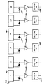
図4を参照すると、フェーズド・アレイ表面コイル36の各々のコイル要素40が前置増幅器56を介して対応する受信増幅器又は受信器54に結合されることが図示されている。各々のコイル要素にはまた、pinダイオードを有する阻止回路網58が設けられている。コイル要素は、その阻止回路網58を選択的に作動することによって、前に述べた理由によりMRデータを取得しないように不作動にすることができる。しかし、商業上入手可能な特定の種類のスキャナによっては、個々のコイル要素を不作動にすること又はターンオフすることは非常に不便であることがある。場合によっては、フェーズド・アレイ・コイルのハードウエアを実質的に再設計して遡及的に適用することが必要になろう。従って、代替の構成では、アレイ36の各々のコイル要素40にデータを取得させるようにする。この場合、上述の手順に従って、或るコイル要素を関心のあるサブセット内に含めないという決定がなされたとき、そのコイル要素に結合されている受信器54が、例えば制御装置32の動作によって、信号処理用電子装置34から切り離されるようにする。このようにして、特定のコイル要素によって取得されたデータは像の再構成のために利用できないようにされる。
【0026】
本発明の別の実施態様では、像の再構成のために計算及び処理用電子装置34によって用いられるアルゴリズムを修正して、関心のあるコイル要素サブセット内に含まれなかったコイル要素からのデータを排除又は無視するようにすることが出来る。
【0027】
上記の教示に従って他の多くの改変及び変更が可能であることは明らかである。従って、本発明は、ここに開示した範囲内で、具体的に述べたもの以外のやり方で実施し得ることを理解されたい。
【図面の簡単な説明】
【図1】本発明の一態様を実施する際に使用されるMRシステムの基本的な構成部品を示す概略線図である。
【図2】フェーズド・アレイ表面コイルにより作成される像の中の或る特定のアーティファクトの原因を説明するのに有用な概略線図である。
【図3】本発明の原理をを説明するのに有用な概略線図である。
【図4】本発明の1つ以上の態様を実施するための構成を例示する概略線図である。[0001]
【Technical field】
The present invention generally relates to an improved method for reducing artifacts in magnetic resonance (MR) images acquired by phased array surface coils. More particularly, the present invention relates to a method of the above type that uses only a subset, but not all, of the coil elements to obtain the MR data necessary to create the image. Even more particularly, the present invention allows an MR scanner or system used to implement the method of the present invention to automatically select a subset of each coil element to be used in acquiring MR data. To a method of the above type that can be easily programmed by an operator.
[0002]
BACKGROUND OF THE INVENTION
As is well known to practitioners in the field of MR imaging, phased array surface coils have been developed to overcome certain deficiencies in other types of MR receivers. More specifically, a phased array coil generally provides a receiver with a better signal-to-noise ratio than a volume coil receiver, and at the same time does not cause the field of view reduction that tends to occur with surface coils. Phased array receivers have been found to be particularly useful for imaging elongated structures such as the cervical, thoracic and lumbar regions of the spine.
[0003]
As is further well known, phased array surface coils are prone to artifacts, and artifacts are required during MR imaging when the value of the required magnetic field, such as B 0 or a gradient field, is within the MR signal source (ie, the object being imaged). Can occur whenever it repeats or repeats at more than one position (in). Such artifacts are primarily derived from the fact that gradients and magnetic coils have a finite length. Thus, the MR scanner's B 0 field or gradient field varies non-linearly with distance from the scanner's main magnet isocenter. For example, an ideal Gz gradient field that is linear with respect to the Z-axis should have a different value at each Z-axis position. However, due to non-linearity, the Gz gradient field can be the same at two Z-axis positions that are widely separated on either side of the isocenter. As a result, MR signals detected at both locations by the receiver may be accepted for use in image reconstruction, even though one location is actually outside the field of view of the image. MR signals from such positions cause artifacts.
[0004]
In a phased array surface coil, such peripheral signal artifacts may appear as bright bright spots or as a ribbon of signals that damage the entire image. Bright spot type artifacts are called startifacts, and ribbon type artifacts are called annefacts.
[0005]
SUMMARY OF THE INVENTION
The present invention generally provides an MR system or scanner to provide an MR image of a region of an object within a specified field of view having dimensions extending between a first boundary and a second boundary. Intended for methods that work. According to this method, a phased array surface coil having a plurality of coil elements is positioned in a selected spatial relationship with respect to the object region. The method further comprises determining or selecting a particular coil element of the array for use in data acquisition, the particular coil extending at least a portion of the array along the phased array. Existing and within a range having a length equal to the size of the field of view, the range being between the positions corresponding to the first and second boundaries, respectively. The selected coil element is activated to acquire MR data from a corresponding subregion of the object region.
[0006]
In a preferred embodiment of the present invention, the phased array surface coil is comprised of a linear array of coil elements, and the MR system is provided with a main magnet having an isocenter, and the positioning step comprises the steps of: Positioning the phased array surface coil such that the coil element is located at a known constant distance from the isocenter. The step of selecting the coil element determines the position of the first and second boundaries with respect to the isocenter, and only when the coil element is located between the position of the first and second boundaries with respect to the isocenter. Selecting the coil element.
[0007]
In a useful aspect, the dimensions of the field of view extending between the first and second boundaries are known, and the respective positions of the first and second boundaries use such dimensions, and the first and second It is determined using a known distance between a landmark on the object located in the middle of the second boundary and the isocenter. In order to determine the position of the first and second ends of each coil element with respect to the isocenter, each of the positions of the first and second ends of a given coil element is defined as the position of the first and second boundaries. In comparison, it is determined whether the given coil element is located between the first and second boundaries.
[0008]
OBJECT OF THE INVENTION
It is an object of the present invention to provide an improved and simplified method for reducing artifacts in MR images acquired by phased array surface coils.
[0009]
Another object of the present invention is to determine or select a particular coil element of a phased array, i.e., a coil element that acquires MR data only from an object region within the field of view of the image, for image data acquisition. It is an object of the present invention to provide a method of the above type adapted to constitute a coil element subset that is used exclusively.
[0010]
Another object of the present invention is to provide a method of the above type in which data acquired by coil elements not included in the subset of the array is not used for image reconstruction.
[0011]
Another object of the present invention is that the MR scanner operator scans the scanner to automatically determine or select the coil elements to be included in the subset of the array by simply providing some available parameters. It is an object of the present invention to provide a method of the above type that can be easily commanded.
[0012]
These and other objects and advantages of the present invention will be readily apparent from the following description with reference to the accompanying drawings.
[0013]
[Detailed Description of Preferred Embodiments]
Referring to FIG. 1, the basic components of an
[0014]
With further reference to FIG. 1, it is illustrated that the
[0015]
Referring to FIG. 2, a patient or other object 16 positioned with respect to the Z axis of the MR system is illustrated. For example, the object 16 is completely or partially contained in the bore of the
[0016]
Still referring to FIG. 2, a portion of an object region or sub-region 44 that exists within the field of
[0017]
FIG. 2 also shows subregions 46 and 48 of the object 16 in which the MR signal is similarly excited by the B 0 and B 1 fields. None of these subregions are included in the field of
[0018]
In accordance with the present invention, coil elements (elements immediately below such an area as viewed in FIG. 2) located near the area of the phased array 36 present in the field of
[0019]
Referring to FIG. 3, there is shown an object 16 and a phased array surface coil 36 positioned relative to each other and relative to the Z axis and
[0020]
Still referring to FIG. 3, a reference mark or
[0021]
After determining the position of the boundary P 1 , the normal logic circuit (not shown) in the electronic device 34 can detect P 1 and each value d i + (e l / 2) stored in the lookup table. ) And systematically. If it is found that P 1 > d i + (e l / 2), the right end of the i-th coil element is located to the left of the left boundary P 1 of the field of
[0022]
In a similar manner, P 2 is compared to each value d i − (e l / 2) stored in the look-up table, ie, the leftmost position of each
[0023]
From the above, the comparison between the boundaries P 1 and P 2 and the position of the end of each coil element is a subset of the
[0024]
It should be emphasized here that it is only necessary to specify the parameters D LM and L in order to select the coil elements of interest for a particular field of view. Such information can easily be supplied to the scanner by the operator, at which time the computing and processing electronics 34 can be processed to perform the comparison described above.
[0025]
Referring to FIG. 4, it is illustrated that each
[0026]
In another embodiment of the present invention, the algorithm used by the computational and processing electronics 34 for image reconstruction is modified to provide data from coil elements not included in the coil element subset of interest. It can be excluded or ignored.
[0027]
Obviously, many other modifications and variations are possible in accordance with the above teachings. Accordingly, it is to be understood that the invention can be practiced otherwise than as specifically described within the scope disclosed herein.
[Brief description of the drawings]
FIG. 1 is a schematic diagram showing the basic components of an MR system used in practicing one aspect of the present invention.
FIG. 2 is a schematic diagram useful for explaining the cause of certain artifacts in an image created by a phased array surface coil.
FIG. 3 is a schematic diagram useful for explaining the principles of the present invention.
FIG. 4 is a schematic diagram illustrating a configuration for carrying out one or more aspects of the invention.
Claims (9)
第1の複数のコイル要素(40)で構成されたフェーズド・アレイ表面コイル(36)を、前記領域(38)に対して、前記MRIシステムのZ方向勾配磁石のアイソセンタを基準にして選択されたZ方向空間関係となるように位置決めすると共に、前記選択された空間関係にある前記フェーズド・アレイ表面コイルの位置パラメータ(DLM、d1,d2,…、el)を記憶する位置決め記憶ステップと、
前記第1の複数のコイル要素(40)から、この第1の複数よりも少ない第2の複数のRFコイル(40)をコンピュータ(34)を用いて選択するステップであって、このコンピュータ(34)は、前記第2の複数のRFコイルに含まれる任意の1つを選択するに際して、この任意の1つのコイルが、前記フェーズド・アレイに沿って延在し且つ前記第1及び第2の境界にそれぞれ対応する位置の間に存在し且つ前記視野の前記寸法に等しい長さ(L)を持つ範囲の中に存在していることを、前記任意のRFコイルの前記位置パラメータとに基づいて演算して確認し、その演算結果に基づいて、前記任意の1つのコイルを前記第2の複数のRFコイルに含ませるものとして選択する演算選択ステップと、
各々の前記選択されたコイル要素をMRIシステム用のRFコイルとして作動させるステップと、
を有することを特徴とするMRI用RFコイルの選択的駆動方法。A specified field of view (42) of a predetermined dimension of the object (16) between the first and second boundaries (P1, P2) that defines the position of the MRI system (10) in the Z-axis direction. In the method for selectively driving the first plurality of RF coils in the MRI system, in order to acquire an MR image of the region (38) within
A phased array surface coil (36) comprised of a first plurality of coil elements (40) was selected with respect to the region (38) relative to the isocenter of the MRI gradient magnet of the MRI system. A positioning storage step for positioning in a Z-direction spatial relationship and storing positional parameters (DLM, d1, d2,..., El) of the phased array surface coil in the selected spatial relationship;
Selecting from the first plurality of coil elements (40) a second plurality of RF coils (40) less than the first plurality using a computer (34), the computer (34); ) In selecting any one of the second plurality of RF coils, the one coil extends along the phased array and the first and second boundaries Calculated based on the position parameter of the arbitrary RF coil and existing in a range having a length (L) equal to the dimension of the field of view. A calculation selecting step of selecting the arbitrary one coil to be included in the second plurality of RF coils based on the calculation result;
Actuating each said selected coil element as an RF coil for an MRI system;
A method of selectively driving an MRI RF coil, comprising:
前記位置決め記憶ステップは、前記フェーズド・アレイの各々のコイル要素が前記アイソセンタから一定の既知の距離の所に位置するように前記フェーズド・アレイ表面コイルを位置決めすることより成る請求項1記載の方法。The phased array comprises a linear array of the coil elements, and the MR system includes the main magnet having the isocenter at a known location;
The method of claim 1, wherein the step of storing and storing comprises positioning the phased array surface coil such that each coil element of the phased array is located at a certain known distance from the isocenter.
前記方法が更に、前記アイソセンタに関してそれぞれのコイル要素の前記第1および第2の端の位置を決定することを含んでおり、
所与のコイル要素の前記第1および第2の端の位置が前記第1および第2の境界と比較されて、前記所与のコイル要素をMRデータの取得に使用するために選択すべきかどうかが決定される請求項3記載の方法。Each of the coil elements has first and second ends in opposing relation to each other;
The method further includes determining a position of the first and second ends of each coil element with respect to the isocenter;
Whether the position of the first and second ends of a given coil element should be compared with the first and second boundaries to select the given coil element for use in acquiring MR data 4. The method of claim 3, wherein is determined.
MRデータの取得に使用するために選択されていない前記フェーズド・アレイの各々のコイル要素は、データ取得の際にそれぞれ不作動にされる請求項5記載の方法。The positions of the first and second ends of the coil element are determined from a known length of the coil and from a known distance between the midpoint of the coil element and the isocenter;
The method of claim 5, wherein each coil element of the phased array that is not selected for use in acquiring MR data is deactivated during data acquisition.
前記物体の領域(38)内でMR信号データを励起する手段と、
前記物体領域(38)に対して、前記MR装置のZ方向勾配磁石のアイソセンタを基準にして選択されたZ方向空間関係にある複数のコイル要素で構成された第1の複数のフェーズド・アレイ表面コイルと、
MRデータを取得するために使用する第2の複数コイル要素を、前記第1の複数のコイル要素の中から選択する電子回路(34)であって、前記第2の複数のRFコイルに含まれる任意の1つを、前記フェーズド・アレイに沿って延在し且つ前記第1及び第2の境界にそれぞれ対応する位置の間に存在し且つ前記所定の寸法に等しい長さ(L)を持つ範囲の中に存在していることを、前記任意のRFコイルの前記位置パラメータとに基づいて演算し、その演算結果に基づいて前記第2の複数のRFコイルに含まれるものとして選択する電子回路(34)と、
前記コイル要素にそれぞれ結合された受信増幅器であって、前記選択されたコイル要素にそれぞれ結合された前記受信増幅器によって受信されたデータのみが前記MR像を構成する際に用いられる前記受信増幅器を有することを特徴とする前記装置。A region (1) in a specified field of view (42) having a predetermined dimension of the object (16) between the first and second boundaries (P1, P2) defining the positioning range in the Z-axis direction ( 38) An MR apparatus for acquiring the MR image of
Means for exciting MR signal data in the region (38) of the object;
A first plurality of phased array surfaces comprising a plurality of coil elements in a Z-direction spatial relationship selected with respect to the object region (38) relative to the isocenter of the Z-direction gradient magnet of the MR device Coils,
An electronic circuit (34) for selecting a second plurality of coil elements to be used for acquiring MR data from the first plurality of coil elements, and is included in the second plurality of RF coils Any one of the ranges extending along the phased array and present between positions corresponding respectively to the first and second boundaries and having a length (L) equal to the predetermined dimension Is calculated based on the position parameter of the arbitrary RF coil and selected as included in the second plurality of RF coils based on the calculation result ( 34)
A receiving amplifier coupled to each of the coil elements, wherein only the data received by the receiving amplifier respectively coupled to the selected coil element is used in constructing the MR image; Said device.
Applications Claiming Priority (2)
| Application Number | Priority Date | Filing Date | Title |
|---|---|---|---|
| US09/096902 | 1998-06-12 | ||
| US09/096,902 US6134465A (en) | 1998-06-12 | 1998-06-12 | Method for reducing artifacts in MR image acquired with phased array surface coil |
Publications (3)
| Publication Number | Publication Date |
|---|---|
| JP2000083923A JP2000083923A (en) | 2000-03-28 |
| JP2000083923A5 JP2000083923A5 (en) | 2008-09-04 |
| JP4584374B2 true JP4584374B2 (en) | 2010-11-17 |
Family
ID=22259645
Family Applications (1)
| Application Number | Title | Priority Date | Filing Date |
|---|---|---|---|
| JP16458099A Expired - Fee Related JP4584374B2 (en) | 1998-06-12 | 1999-06-11 | MRI apparatus and phased array surface coil selective driving method |
Country Status (4)
| Country | Link |
|---|---|
| US (1) | US6134465A (en) |
| JP (1) | JP4584374B2 (en) |
| DE (1) | DE19926491A1 (en) |
| IL (1) | IL130252A0 (en) |
Families Citing this family (18)
| Publication number | Priority date | Publication date | Assignee | Title |
|---|---|---|---|---|
| US6323648B1 (en) * | 1997-11-26 | 2001-11-27 | Medrad, Inc. | Peripheral vascular array |
| JP2001198100A (en) * | 2000-01-20 | 2001-07-24 | Ge Medical Systems Global Technology Co Llc | Mr data gathering method, mr image display method and mri device |
| DE10003712C2 (en) * | 2000-01-28 | 2002-12-12 | Siemens Ag | Method of selecting a local antenna |
| US6946836B2 (en) * | 2000-04-25 | 2005-09-20 | Kabushiki Kaisha Toshiba | Magnetic resonance imaging involving movement of patient's couch |
| US6724923B2 (en) * | 2001-04-13 | 2004-04-20 | Ge Medical Systems Global Technology Co., Llc | Automatic coil selection of multi-receiver MR data using fast prescan data analysis |
| US6738501B2 (en) | 2001-04-13 | 2004-05-18 | Ge Medical Systems Global Technology Co., Llc | Adaptive data differentiation and selection from multi-coil receiver to reduce artifacts in reconstruction |
| US7894876B2 (en) * | 2004-02-02 | 2011-02-22 | Siemens Medical Solutions, Inc. | Combined MR-optical coil for prostate, cervix and rectum cancer imaging diagnostics |
| US7714576B2 (en) * | 2004-08-05 | 2010-05-11 | Koninklijke Philips Electronics N.V. | Automatic selection of a receiver element in an MRI apparatus |
| JP2006175058A (en) * | 2004-12-22 | 2006-07-06 | Ge Medical Systems Global Technology Co Llc | Coil element selecting method and magnetic resonance imaging apparatus |
| CN101473239A (en) * | 2006-06-22 | 2009-07-01 | 皇家飞利浦电子股份有限公司 | Magnetic resonance receive coil array integrated into wall of scanner bore |
| WO2010120829A2 (en) | 2009-04-14 | 2010-10-21 | The Board Of Trustees Of The Univerisity Of Illinois | Method for reducing artifacts in magnetic resonance imaging |
| JP6407620B2 (en) * | 2014-08-11 | 2018-10-17 | キヤノンメディカルシステムズ株式会社 | Magnetic resonance imaging system |
| US10390725B2 (en) | 2015-02-17 | 2019-08-27 | Siemens Aktiengesellschaft | Connection of coils to an MR device |
| DE102015202793A1 (en) * | 2015-02-17 | 2016-08-18 | Siemens Healthcare Gmbh | Connecting coils to an MR device |
| DE102015202795B4 (en) * | 2015-02-17 | 2018-11-22 | Siemens Healthcare Gmbh | Connecting coils to an MR device |
| JP2017046796A (en) * | 2015-08-31 | 2017-03-09 | 東芝メディカルシステムズ株式会社 | Magnetic resonance imaging apparatus |
| CN105476635B (en) | 2015-12-29 | 2019-02-05 | 沈阳东软医疗系统有限公司 | The localization method and device of radio-frequency coil in a kind of MRI system |
| CN108303674A (en) * | 2018-01-03 | 2018-07-20 | 上海东软医疗科技有限公司 | The localization method and device of magnetic resonance imaging system receiving coil |
Citations (2)
| Publication number | Priority date | Publication date | Assignee | Title |
|---|---|---|---|---|
| JPH0565179B2 (en) * | 1990-05-31 | 1993-09-17 | Tokyo Shibaura Electric Co | |
| JPH11276452A (en) * | 1998-03-31 | 1999-10-12 | Shimadzu Corp | Mr imaging method and device therefor |
Family Cites Families (9)
| Publication number | Priority date | Publication date | Assignee | Title |
|---|---|---|---|---|
| US924868A (en) * | 1908-02-17 | 1909-06-15 | Winfield Mfg Company | Electric-welding machine. |
| JP3110741B2 (en) * | 1990-07-18 | 2000-11-20 | 株式会社東芝 | Magnetic resonance imaging equipment |
| US5138260A (en) * | 1990-11-21 | 1992-08-11 | Picker International, Inc. | Computer controlled switching of multiple rf coils |
| US5399970A (en) * | 1993-08-11 | 1995-03-21 | Board Of Trustees Of The Leland Stanford Junior University | Phase-contrast MRI using phased-array multicoil |
| EP0695947B1 (en) * | 1994-08-03 | 2001-11-14 | Philips Patentverwaltung GmbH | MR method for determining the distribution of nuclear magnetization with a surface coil arrangement |
| US5551430A (en) * | 1994-08-05 | 1996-09-03 | Picker International, Inc. | RF coil identification and testing interface for NMR systems |
| US5945826A (en) * | 1996-08-28 | 1999-08-31 | U.S. Philips Corporation | MR device with a reference coil system for the reconstruction of MR images from a coil array |
| US5910728A (en) * | 1996-11-12 | 1999-06-08 | Beth Israel Deaconess Medical Center | Simultaneous acquisition of spatial harmonics (SMASH): ultra-fast imaging with radiofrequency coil arrays |
| US5928148A (en) * | 1997-06-02 | 1999-07-27 | Cornell Research Foundation, Inc. | Method for performing magnetic resonance angiography over a large field of view using table stepping |
-
1998
- 1998-06-12 US US09/096,902 patent/US6134465A/en not_active Expired - Lifetime
-
1999
- 1999-06-02 IL IL13025299A patent/IL130252A0/en unknown
- 1999-06-10 DE DE19926491A patent/DE19926491A1/en not_active Withdrawn
- 1999-06-11 JP JP16458099A patent/JP4584374B2/en not_active Expired - Fee Related
Patent Citations (2)
| Publication number | Priority date | Publication date | Assignee | Title |
|---|---|---|---|---|
| JPH0565179B2 (en) * | 1990-05-31 | 1993-09-17 | Tokyo Shibaura Electric Co | |
| JPH11276452A (en) * | 1998-03-31 | 1999-10-12 | Shimadzu Corp | Mr imaging method and device therefor |
Also Published As
| Publication number | Publication date |
|---|---|
| US6134465A (en) | 2000-10-17 |
| JP2000083923A (en) | 2000-03-28 |
| DE19926491A1 (en) | 1999-12-16 |
| IL130252A0 (en) | 2000-06-01 |
Similar Documents
| Publication | Publication Date | Title |
|---|---|---|
| JP4584374B2 (en) | MRI apparatus and phased array surface coil selective driving method | |
| JP5209895B2 (en) | Magnetic resonance system control method, magnetic resonance system, and computer program | |
| US7777485B2 (en) | Method for multiplexed MR tracking | |
| US6288545B1 (en) | Method and apparatus for calibration of RF and gradient field time delays | |
| US6990223B2 (en) | Adaptive data differentiation and selection from multi-coil receiver to reduce artifacts in reconstruction | |
| US7358731B2 (en) | Determination of spatial sensitivity profiles of RF coils in magnetic resonance imaging | |
| US6586935B1 (en) | Magnetic resonance image artifact correction using navigator echo information | |
| US7977943B2 (en) | Method and system for reconstructing images | |
| JP2005131411A (en) | System and method for calibrating coil sensitivity profiles | |
| JP2006175223A (en) | Method and system for spatial-spectrum excitation by parallel radio frequency transmission | |
| US11287493B2 (en) | Magnetic resonance imaging method and system and computer-readable storage medium | |
| JP4447104B2 (en) | Magnetic resonance equipment | |
| US11733325B2 (en) | Method for controlling an MR apparatus | |
| JP3705995B2 (en) | Gradient coil manufacturing method, gradient coil, and magnetic resonance imaging apparatus | |
| JP4960575B2 (en) | Automatic imaging area optimization to maximize resolution and eliminate aliasing artifacts | |
| NL1026189C2 (en) | Systems and method for gradient compensation in magnetic resonance imaging. | |
| US7812603B2 (en) | Method for determining local deviations of a main magnetic field of a magnetic resonance device | |
| NL1030693C2 (en) | Method and system for MR scan acceleration using selective excitation and parallel transmission. | |
| JP4247511B2 (en) | Gradient magnetic field measuring method and apparatus, and magnetic resonance imaging apparatus | |
| US6819105B2 (en) | System and methods for enhancing quality of images affected by a motion of a subject | |
| US6747451B2 (en) | Method for avoiding over-convolutions in the phase coding direction in nuclear magnetic resonance tomography | |
| JP7383386B2 (en) | magnetic resonance imaging device | |
| JP2004154399A (en) | Group delay optimization method and magnetic resonance imaging unit | |
| US20030023157A1 (en) | Method for the operation of a magnetic resonance apparatus | |
| JP2005528174A (en) | MR imaging method comprising using means to control chemical shift |
Legal Events
| Date | Code | Title | Description |
|---|---|---|---|
| RD02 | Notification of acceptance of power of attorney |
Free format text: JAPANESE INTERMEDIATE CODE: A7422 Effective date: 20000630 |
|
| RD04 | Notification of resignation of power of attorney |
Free format text: JAPANESE INTERMEDIATE CODE: A7424 Effective date: 20000630 |
|
| A621 | Written request for application examination |
Free format text: JAPANESE INTERMEDIATE CODE: A621 Effective date: 20060607 |
|
| A521 | Request for written amendment filed |
Free format text: JAPANESE INTERMEDIATE CODE: A523 Effective date: 20080722 |
|
| RD02 | Notification of acceptance of power of attorney |
Free format text: JAPANESE INTERMEDIATE CODE: A7422 Effective date: 20090406 |
|
| RD04 | Notification of resignation of power of attorney |
Free format text: JAPANESE INTERMEDIATE CODE: A7424 Effective date: 20090406 |
|
| A131 | Notification of reasons for refusal |
Free format text: JAPANESE INTERMEDIATE CODE: A131 Effective date: 20090512 |
|
| A601 | Written request for extension of time |
Free format text: JAPANESE INTERMEDIATE CODE: A601 Effective date: 20090812 |
|
| A602 | Written permission of extension of time |
Free format text: JAPANESE INTERMEDIATE CODE: A602 Effective date: 20090817 |
|
| A521 | Request for written amendment filed |
Free format text: JAPANESE INTERMEDIATE CODE: A523 Effective date: 20091112 |
|
| A521 | Request for written amendment filed |
Free format text: JAPANESE INTERMEDIATE CODE: A523 Effective date: 20091112 |
|
| A02 | Decision of refusal |
Free format text: JAPANESE INTERMEDIATE CODE: A02 Effective date: 20091222 |
|
| A521 | Request for written amendment filed |
Free format text: JAPANESE INTERMEDIATE CODE: A523 Effective date: 20100422 |
|
| A911 | Transfer to examiner for re-examination before appeal (zenchi) |
Free format text: JAPANESE INTERMEDIATE CODE: A911 Effective date: 20100601 |
|
| A131 | Notification of reasons for refusal |
Free format text: JAPANESE INTERMEDIATE CODE: A131 Effective date: 20100706 |
|
| A521 | Request for written amendment filed |
Free format text: JAPANESE INTERMEDIATE CODE: A523 Effective date: 20100715 |
|
| TRDD | Decision of grant or rejection written | ||
| A01 | Written decision to grant a patent or to grant a registration (utility model) |
Free format text: JAPANESE INTERMEDIATE CODE: A01 Effective date: 20100803 |
|
| A01 | Written decision to grant a patent or to grant a registration (utility model) |
Free format text: JAPANESE INTERMEDIATE CODE: A01 |
|
| A61 | First payment of annual fees (during grant procedure) |
Free format text: JAPANESE INTERMEDIATE CODE: A61 Effective date: 20100902 |
|
| R150 | Certificate of patent or registration of utility model |
Free format text: JAPANESE INTERMEDIATE CODE: R150 |
|
| FPAY | Renewal fee payment (event date is renewal date of database) |
Free format text: PAYMENT UNTIL: 20130910 Year of fee payment: 3 |
|
| R250 | Receipt of annual fees |
Free format text: JAPANESE INTERMEDIATE CODE: R250 |
|
| LAPS | Cancellation because of no payment of annual fees |