JP4583695B2 - Keyboard / video / mouse switching system via network - Google Patents
Keyboard / video / mouse switching system via network Download PDFInfo
- Publication number
- JP4583695B2 JP4583695B2 JP2001580647A JP2001580647A JP4583695B2 JP 4583695 B2 JP4583695 B2 JP 4583695B2 JP 2001580647 A JP2001580647 A JP 2001580647A JP 2001580647 A JP2001580647 A JP 2001580647A JP 4583695 B2 JP4583695 B2 JP 4583695B2
- Authority
- JP
- Japan
- Prior art keywords
- server
- keyboard
- interface
- mouse
- network
- Prior art date
- Legal status (The legal status is an assumption and is not a legal conclusion. Google has not performed a legal analysis and makes no representation as to the accuracy of the status listed.)
- Expired - Lifetime
Links
Images


Classifications
-
- G—PHYSICS
- G06—COMPUTING; CALCULATING OR COUNTING
- G06F—ELECTRIC DIGITAL DATA PROCESSING
- G06F3/00—Input arrangements for transferring data to be processed into a form capable of being handled by the computer; Output arrangements for transferring data from processing unit to output unit, e.g. interface arrangements
- G06F3/01—Input arrangements or combined input and output arrangements for interaction between user and computer
- G06F3/03—Arrangements for converting the position or the displacement of a member into a coded form
- G06F3/033—Pointing devices displaced or positioned by the user, e.g. mice, trackballs, pens or joysticks; Accessories therefor
- G06F3/038—Control and interface arrangements therefor, e.g. drivers or device-embedded control circuitry
-
- G—PHYSICS
- G06—COMPUTING; CALCULATING OR COUNTING
- G06F—ELECTRIC DIGITAL DATA PROCESSING
- G06F3/00—Input arrangements for transferring data to be processed into a form capable of being handled by the computer; Output arrangements for transferring data from processing unit to output unit, e.g. interface arrangements
- G06F3/01—Input arrangements or combined input and output arrangements for interaction between user and computer
- G06F3/02—Input arrangements using manually operated switches, e.g. using keyboards or dials
- G06F3/023—Arrangements for converting discrete items of information into a coded form, e.g. arrangements for interpreting keyboard generated codes as alphanumeric codes, operand codes or instruction codes
Abstract
Description
【0001】
1.発明の属する技術分野
本発明は、ネットワーク切り替えシステムに関し、さらに詳しくはコンピュータ周辺データのネットワーク切り替えに関する。
【0002】
本発明の背景および概要
数年前、企業ネットワークが拡大し始めた頃から、1台のワークステーションのキーボード、ディスプレイ、マウスによって1人のネットワークオペレータが複数の異なるコンピュータをアクセスおよび制御できる、いわゆるKVM(キーボード・ビデオ・マウス)スイッチの需要が増した。当初KVMスイッチは、保守オペレータが1セットのキーボード、ディスプレイ、マウスで2台から8台のコンピュータをアクセスできる機能を提供していた。しかしながら企業ネットワークのサイズが拡大するにつれ、KVMスイッチの複雑さも増した。その結果コンピュータネットワークオペレータは、1台のワークステーションと数千台あるいは数万台のコンピュータとの間のアクセスをKVMスイッチに求めるようになった。これに対する最初の回答は、例えば1台のワークステーションから8台のサーバへのアクセスを提供する1台のKVMスイッチを、別の8台のKVMスイッチへアクセスできるように拡大し、8x8=64台のコンピュータへのアクセスを提供することであった。このような方法で1セットのキーボード、ディスプレイ、マウスから多数のコンピュータにアクセスできる。
【0003】
大規模化は、現在多くのコンピュータ環境において有望な選択肢である。しかしながら、サーバファーム等において極めて多数のコンピュータを導入することが一般的になると、1人のネットワークオペレータが数万台あるいはそれ以上のコンピュータをアクセスする必要性が急務になる。もちろんKVMスイッチを増やし、多数のコンピュータを数台のワークステーションで操作することは可能だが、KVMスイッチを増やせばサーバファームにおけるスペースの問題が生じる。
【0004】
図1および2は、従来のKVMスイッチの例を示す。図1において、従来の企業ネットワーク10は例えばLAN、WAN、インターネットであり、多数のサーバ11〜13に通信路を提供する。これらサーバの動作および企業ネットワーク10が使用する通信プロトコルは、当業者が良く知るところである。簡潔のため、それらの説明は省略する。当業者には明らかな通り、サーバ11〜13は、多くの異なるプロトコルを用いてネットワーク10での通信を行える。多くのプロトコルが将来開発されれば、サーバ11〜13によるネットワークデータ伝送効率が高まるであろう。本発明は、特定のプロトコルに制限されるものではない。
【0005】
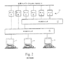
図2は、KVMスイッチ環境を示す。多数のワークステーション17〜19は、KVMスイッチ16を介し、サーバセット14のサーバAおよびBと通信する。各サーバ14は、企業ネットワーク10を介し、互いにあるいは他のサーバと通信する。図2は、KVMスイッチの拡大機能を示しており、KVMスイッチ16の出力ポートの1つは、第2KVMスイッチ15に接続する。そして第2KVMスイッチ15は、サーバセット14の4台のサーバC〜Fに接続する。KVMスイッチ16が4個の出力ポートしか持っていなくとも、KVMスイッチ15を追加することにより、ユーザ17〜19は4台以上のサーバ(図2の場合6台のサーバ14)と通信できる。
【0006】
KVMスイッチ15および16は、既知の装置であり市販されている。例えばアラバマ州ハンツビルのサイベックス社が販売するオートビューファミリー製品およびエックスピーファミリー製品である。KVMスイッチ15および16は、図2の例において多くの機能を提供する。第1にKVMスイッチは、サーバ14を起動する時、キーボード、ビデオ、マウスの初期コマンドをエミュレートし、各コンピュータ14が1台のワークステーションのキーボード、ディスプレイ、マウスに接続されているかのように各コンピュータ14に信じ込ませる。KVMスイッチは、キーボード、ビデオ、マウス限定コマンドをエミュレートすべく、様々なKVM規格の1つに基づきプログラムされている。これら規格は、例えばキーボード・マウス用のSUN、PS2等であり、ディスプレイ用のVGA、SVGA等である。さらにKVMスイッチ15および16は、ワークステーションのシステム要求(マウスタイプ、ディスプレイタイプ、キーボードタイプ等)をポーリングし、不整合なキーボード、ディスプレイ、マウス間のデータ変換を行い、サーバ14と通信する。
【0007】
初期タイプのKVMスイッチの1つは、パーホルツ等による米国特許第5,732,212号「パーソナルコンピュータの遠隔監視および操作用システムおよび方法」が開示する。パーホルツは、電話ネットワークを介した遠隔KVM切り替えと、コンピュータのデイジーチェーンを介した局所切り替えとを開示する。パーホルツは、電話回線を介してワークステーションと通信するホストシステムを使用し、選択したコンピュータのマザーボードにアクセスする方法を記述している。すなわちパーホルツは、本来ならば局所的にマザーボードをアクセスしなければならないリブート、コールドブート等の機能を、遠隔のホスト装置を使用してマザーボードをアクセスすることによって実現する方法を開示している。
【0008】
本発明は、従来のKVMスイッチおよび遠隔アクセスKVMスイッチを大幅に改良する。本発明が提供するKVM切り替えは、従来の規模拡大KVMスイッチを使用することなく、あるいは従来の遠隔アクセス装置を使用することなく、ネットワーク上のあらゆる数のサーバにアクセス可能であり、これらサーバのマザーボードにもアクセス可能である。従来のネットワークアクセスシステムにおいて、ネットワークを経由して通信するワークステーションとサーバは、互いにキーボード、ビデオ、マウスコマンドデータをパケット情報の形式で交換する。このため市販されているピーシーエニホエア(PCAnywhere)等の従来の遠隔システムは、電話ネットワークやインターネットを経由してサーバにアクセスし、当該サーバのキーボード、ディスプレイ、マウスにアクセスする。しかしながらこのような従来システムのユーザは、例えば企業LANやインターネット上に存在する多くのサーバにアクセスする時、これらサーバのマザーボードにアクセスすることはできない。すなわちこれまでのユーザは、マザーボードアクセスを提供するものの規模が限られた従来のKVMスイッチを選択するか、あるいは多数のサーバにアクセスできるもののマザーボードの直接アクセスはできない遠隔アクセススイッチを選択するかだけであった。
【0009】
本発明は、これら問題を解決し、比較的簡単な構造によって、いかなる数のワークステーションからでも、企業ネットワーク、インターネット等のネットワークに存在するいかなる数のサーバのキーボード、ディスプレイ、マウスでもアクセスできるようにする。本発明の好適な実施の形態において、多数のサーバは、企業ネットワークを介して通信する。これらサーバの各々のキーボード、ビデオ、マウスポートは、対応する変換器ボックスにケーブルを介して接続する。これら変換器ボックスは保守ネットワークと通信し、この保守ネットワークは多数のユーザワークステーションと通信する。この実施の形態において、前記ワークステーションの1台のユーザが前記サーバの1台にアクセスする場合、そのユーザワークステーションは、前記保守ネットワークを介して当該サーバに対応する変換器ボックスと通信し、そのサーバへのマザーボードアクセスを獲得する。次にそのユーザは、前記サーバを使用し、前記企業ネットワークを介して他のサーバと通信できる。
【0010】
なお本明細書において変換器「コア」および/または「ユニット」と称する場合、この変換器は必ずしも「ボックス」または「ユニット」である必要はなく、コンピュータカード、サーバカード、またはシステム部品に内蔵できる要素等でも構わない。
【0011】
本発明の好適な実施の形態において、いかなる数のユーザでも前記保守ネットワーク上で通信でき、いかなる数のサーバでも前記企業ネットワークで通信でき、どのユーザでもいずれのサーバとも通信でき、全サーバは互いに通信でき、従来の規模拡大KVMスイッチを必要とせず、従来のKVM遠隔アクセス装置を必要とせず、マザーボードの完全アクセスを実現する。このように好適な実施の形態は、基本的に無制限の規模拡大性を提供すると共に、各ユーザにいずれのサーバのマザーボードでもアクセスできるようにする。
【0012】
他の実施の形態において、安全確保手順を使用することにより、特定のあるいは全てのサーバのマザーボードアクセスを特定のあるいは全てのワークステーションに限定できる。
【0013】
他の実施の形態において、前記企業ネットワークおよび保守ネットワークは、互いに独立したネットワークではなく共通ネットワークで良い。
【0014】
さらに他の実施の形態において、前記変換器は各サーバに別々に割り当てたものでなく、1つ以上のサーバに対して動作できる。
【0015】
さらに他の実施の形態において、前記保守ネットワークおよび企業ネットワークは、相互接続できる。
【0016】
発明を実施するための最良の形態
図3は、企業LAN10において互いに通信するサーバ11〜13を示す。企業LAN10は一般的なLANであり、サーバ11〜13も一般的な市販サーバであり、例えば図1の従来例に示したものである。
【0017】
本発明に基づき、サーバ11,12,13は、それぞれ変換器21、22,23と通信する。これら変換器は、保守ネットワーク20と通信する。ユーザワークステーション25,26,27は、保守ネットワーク20と通信し、変換器21,22,23と通信する。
【0018】
図3は、3台のサーバ、3台のワークステーション、2つのネットワークを示すが、本発明は図3に示した特定の実施の形態に限定されるものではなく、図示の各構成部は図示より多くても少なくても構わない。独立した変換器ユニット21〜23を使用することにより、市販のサーバをそのままサーバ11〜13として利用できる。しかしながら変換器21〜23は、例えばコンピュータプラグインカードとしてサーバ11〜13に内蔵しても良い。
【0019】
変換器21,22,23は、サーバ11〜13と保守ネットワーク20との間に仲介手段として介在する。仲介用変換器21〜23の存在により、サーバ11〜13は一般的なサーバで良く、例えば市販のパーソナルコンピュータでも構わない(ただしそれに限定するものではない)。好適な実施の形態において、変換器21〜23は、1対1でサーバ11〜13に接続できる。例えば変換器21はサーバ11に接続し、変換器22はサーバ12に接続し、変換器23はサーバ13に接続する。本実施の形態において、企業ネットワーク10上の各サーバ(図3より多くても良い)は、保守ネットワーク20と通信する前に、それぞれの変換器を有する(または少なくとも共有の変換器と通信する)。
【0020】
1つの実施の形態において、変換器21は、KVM信号をLANプロトコルに変換できるよう、公知のKVMスイッチを変更したものでも良い。このような公知スイッチの一例は、ピンクストンの米国特許出願第09/379,576号に記載があり、参照によりここに組み込む。変換器21は、図2の従来のKVMスイッチがパーソナルコンピュータに接続するように、例えばサーバ11に接続する。すなわち変換器21は、ケーブルを介して、サーバ11のキーボード、ビデオ、マウスポートに接続し、変換器21からサーバ11のマザーボードへの直接アクセスを実現し、選択した1つのユーザワークステーション25〜27のキーボード、ディスプレイ、マウスがあたかも当該サーバに直接接続しているようにする。変換器21と保守ネットワーク20との間には、ネットワークカードが存在し、それによって変換器21は、保守ネットワーク20から受信する信号をサーバ11が必要とするキーボード、ビデオ、マウス信号へ変換する。同様に変換器21は、サーバ11からキーボード、ビデオ、マウス信号を受け取り、それらを保守ネットワーク20が受け取り可能なデータプロトコルのパケットにする(あるいはフォーマットする)。
【0021】
ユーザワークステーション25〜27は、保守ネットワーク20を介して変換器21〜23と通信する。好適な実施の形態において、保守ネットワーク20は、図3に示すように、企業ネットワーク10とは完全に別のネットワークである。保守ネットワーク20は、企業ネットワーク10と同じプロトコルで動作できるが、そうである必要もない。保守ネットワーク20と企業ネットワーク10とは、各々イーサネット、LAN、ATM、無線、CAT−5、TCP/IPプロトコル、あるいは装置間の相互通信を可能にする他のデータネットワーク接続またはプロトコルに従うことができる。
【0022】
ユーザワークステーション、例えばワークステーション25がサーバ、例えばサーバ13と通信する場合、ワークステーション25は、変換器23宛のデータを保守ネットワーク20へ送る。変換器23は、ワークステーション自身と同様、ネットワーク20上に装置アドレスを割り当てられている。多くの場合、ワークステーション25から変換器23へ送るデータは、ワークステーション25のキーボードおよびマウス(または他の入力機器)からの入力であり、選択したサーバ13を制御するためのものである。ワークステーションは、前記変換器23へのデータを、保守ネットワーク20が指定するアドレスプロトコルに対応する標準ネットワークデータアドレス指定に基づいて作成する。このためワークステーション25〜27は、ワークステーション25〜27を保守ネットワーク20へリンクさせるネットワークカードを含む。このネットワークカードは、相手の変換器21〜23に関して、保守ネットワーク20におけるデータアドス指定を支援する。ワークステーション25は、キーボードおよびマウスデータを変換器23へ送り出し、変換器23はそれらを保守ネットワーク20から受け取り、サーバ13が必要とするフォーマットの標準キーボードおよびマウスプロトコルに変換し、それら信号をサーバ13のキーボードおよびマウスポートへ送る。最後にユーザワークステーション25は、あたかもワークステーション25のキーボードおよびマウスがサーバ13に直接接続しているかのように、サーバ13への直接アクセスを得る。
【0023】
これと逆方向において、前記変換器は、サーバ13からのデジタルビデオデータをパケットにし、ネットワーク20を介してワークステーションのディスプレイへ送る。
【0024】
前段落では1方向のように説明したが、変換器23とワークステーション25との間は双方向通信である。キーボードおよびマウスコマンドデータを、例えばサーバ13から変換器23へそしてワークステーション25へ送り、マウス感度やキーボードライトを設定できる。またビデオコマンドをワークステーション25のディスプレイからサーバ13へ変換器23を介して適宜送ることができる。
【0025】
変換器21〜23は、ワークステーション25〜27がサーバ11〜13のいずれかと通信するため、必要なあらゆる仲介ステップを実行する。すなわち変換器21〜23は、サーバ11〜13の起動に応答し、サーバ11〜13が必要とする適切なキーボード、ディスプレイ、マウスの初期応答を提供し、各サーバにあたかも適切なキーボード、ディスプレイ、マウスが接続されているように信じ込ませる。
【0026】
図3から明らかな通り、あらゆる数のワークステーション25〜27(保守ネットワーク20が保守可能な数によってのみ制限される)が、あらゆる数のサーバ11〜13と通信できる。KVM信号切り替え規模を、KVMスイッチの物理的制限を受けずに拡大できる。
【0027】
図3に示す企業ネットワーク10は例示しただけであり、本発明に必須ではない。しかしながら、現在ほとんどのサーバ11〜13は、企業ネットワーク10を介して互いに通信を行っている。
【0028】
図4は、図3の実施の形態に加え、ユーザ25〜27がインターネット28と通信できるようにしたものである。図4の実施の形態において、保守ネットワーク20は、ゲートウエイ/ファイアウオール29と通信し、ゲートウエイ/ファイアウオール29はユーザワークステーション25〜27をインターネット28に接続する。さらに別の実施の形態として、企業ネットワーク10をインターネット28で置き換え、保守ネットワーク20がインターネット28を介してサーバ11〜13の各々と通信しても良い。
【0029】
さらに図4は、保守ネットワーク20と通信する管理サーバ30を示す。これによりネットワーク管理者は、保守ネットワーク20を管理し、その保守ネットワーク20に属する各装置と通信できる。
【0030】
図5は、図3の実施の形態を変更した実施の形態を示す。図5において、企業ネットワーク10は、多数のサーバ31による通信ネットワークバックボーンを提供する。図5の実施の形態において、8台のサーバA〜Hは、1台の8×1変換器32と通信する。この8×1変換器32は保守ネットワーク20と通信し、この保守ネットワーク20はワークステーション25〜27(図3)と通信する。図5と図3の違いは、変換器32が多数の独立した変換器21〜23(例えば図3)に置き換わっていることである。ワークステーション25〜27の1台がサーバ31のいずれか1台と通信する場合、そのワークステーションは、適切なアドレス指定情報をサーバへ送り、8×1変換器32はそのデータを8台のサーバ31の全体に対して受け取り、それをサーバA〜Hの適切なポートへのデータに分離し、各キーボード・ビデオ・マウスデータを対応するサーバへ送る。このように図5の実施の形態では、変換器32はキーボード・ビデオ・マウスデータを保守ネットワーク20から取り出し、それを1台のサーバのキーボード、ビデオ、マウスポート用信号データに変換するだけでなく、保守ネットワーク20から受信したデータを分類しそれを8台のサーバのいずれかへ送る。もちろん他の拡大率(8×1以外)を変換器32に適用しても構わない。
【0031】
図7を参照してサーバおよび変換器の概略構成を説明する。図7において、サーバ41は、マザーボード42と、ネットワークカード43と、ビデオカード44とを含む。もちろん他の部品をサーバ41に含めても構わないが、簡略のためそれらは図示しない。サーバ41は、標準的なパーソナルコンピュータとし、ネットワークPCIカードを備えることによって当該パーソナルコンピュータをネットワーク35経由で通信可能にすることができる。ネットワーク35は、LANあるいは他のネットワークで良く、イーサネット、IP/TCP等のデータプロトコルに基づくことができる。ただしこれらに限定されない。公知の通りサーバ41は、マザーボード42のキーボードおよびマウスポートに接続したキーボードおよびマウスからキーボードおよびマウス命令を受け取り、それら命令をマザーボード上のプロセッサを用いて処理し、適切なデータ信号を生成できる。これらデータ信号は、ネットワークカード43を介してネットワーク35へ送出する。さらにマザーボード42は、前記キーボードおよびマウス信号に対し、ビデオプロセッサを介して応答できる。このビデオプロセッサは、ビデオカード44からビデオポートへビデオリフレッシュ信号を送る。本発明において変換器47は、サーバ41のビデオ、キーボード、マウスポートに直接接続する。特にサーバ41のビデオカード44からのビデオポートは、変換器47のビデオポート45に接続する。同様にサーバ41のキーボードおよびマウスポート(マザーボード42に直接接続する)は、変換器47のキーボードおよびマウスポート46に接続する。変換器47が図5に示したタイプ(複数サーバ用)である場合、変換器47はn台のサーバ用にビデオ、キーボード、マウスポート48…49を含む。
【0032】
さらに変換器47は、変換器47のネットワークカード(図示せず)を介し、ネットワーク接続50を経由して保守ネットワーク20と通信する。保守ネットワーク20は、LAN、イーサネット、ATM、IP/TCP、無線、CAT−5等に基づくことができる。接続50および変換器47のネットワークカードは、ネットワーク20が使用するネットワークプロトコルに対応する。保守ネットワーク20は、少なくとも1つのワークステーション51あるいはさらに別のワークステーション(図示せず)と通信する。
【0033】
図7に示す通り、変換器47は、保守ネットワーク20を介して変換器47と通信するワークステーション51と、サーバ41のマザーボード42との間を仲介する。変換器47は、アラバマ州ハンツビルのサイベックスコンピュータプロダクト社が販売するいわゆる「キービューII」製品で良く、この製品は1999年9月22日出願の米国特許出願第09/401,501号「パーソナルコンピュータを遠隔アクセスおよび操作するためのシステムおよび方法」に開示されており、この開示の全てを参照により組み込む。変換器47は、サーバ41のキーボードおよびマウスポートへ直接接続しているため、サーバ41のマザーボード42へ直接アクセスする。これにより変換器47は、マザーボードへの直接アクセスによってのみ可能なマザーボード42のコールドブート等の機能を実行できる。このように図7の実施の形態は、マザーボード42の機能をワークステーション51が操作することを可能にする。これら機能は、ワークステーション51が単純にネットワーク35に接続し、サーバ41のネットワークカード43およびPCIバスを介してマザーボード42と通信しているだけでは、実現できないものである。
【0034】
従って本発明は、サーバネットワークカード、サーバモデム等を介してサーバと通信する従来の遠隔アクセス装置とは実質的に異なる。なぜなら従来システムはマザーボードへの直接アクセスを実現できないのに対し、本発明のコンピュータはサーバのキーボードおよびマウスポートを介してそれを実現できるからである。
【0035】
図7に示す通り、サーバ41は、標準マザーボード42と標準ビデオカード44と標準キーボード・マウスポートとを備えた標準的な市販サーバでよい。またワークステーション51は、どのようなタイプでも良く、選択したサーバ41と互換性が無くても構わない。例えば非限定的な例を上げれば、ワークステーション51はサンタイプのワークステーションであり、サーバ41はパーソナルコンピュータサーバであり、変換器47はワークステーション51とサーバ41との通信を可能にするための必要な変換を提供するものである。図7の実施の形態における変換器は、市販ワークステーション51と市販コンピュータ41とを使用できるという便宜をユーザに提供する。
【0036】
変換器47の変換機能は、サーバ41に内蔵しても良い。しかしながらこの変更した実施の形態の場合、サーバ41をカスタマイズして変換器47のハードウエアおよびソフトウエアをそこに含めねばならない。このように本発明は、標準的な市販サーバと外部変換器47とで実現することもでき、マザーボードの直接アクセスを提供する変換器47の特性を有する変換器カードを含むようにサーバ41をカスタマイズして実現することもでき、変換器機能をシステムのサーバのどこかに使用した状態で実現することもできる。
【0037】
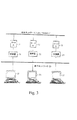
さらに本発明は、従来のサーバカード36(図6)とも異なる。この従来品は、キーボードおよびマウスコマンド39とビデオコマンド40とを受け取り、それらコマンドをネットワークパケットに変換してネットワーク35へ送る。図6に示す通り、いくつかの従来システムは、キーボードおよびマウスデータ39を受け取り、そのデータをパケット化機能37においてパケットにし、パケット化したキーボードおよびマウスコマンドをネットワーク35へ送る。このようなサーバカード36は、ビデオ−コマンド変換器38においてビデオ信号40を受け取り、そのビデオ信号をコマンドタイプ(例えば座標XYから座標X1Y1へ線を引く)に変換し、そのコマンドをパケット化機能37においてパケットにし、そのパケットをネットワーク35へ送る。これに対し本発明は、例えば図7に示す通り、デジタルビデオをビデオポート45からネットワークポート50へ直接送り、保守ネットワーク20を介してワークステーション51のディプレイへ送り、ワークステーションのキーボードおよびマウスによるマザーボード直接アクセスを、マザーボード42へのキーボードおよびマウスポート46を介して提供する。あるいは本発明は、デジタルビデオをサーバのビデオフレームバッファから直接取ることもできる。
【0038】
変換器47は、ビデオポート45において生ビデオデータを受け取るため、サーバ41のディスプレイ解像度を変換してワークステーション51のディスプレイが要求する解像度に合わせることができる。このため変換器47は、ビデオポート45のサイズ調整および解像度変換を提供すると共に、保守ネットワーク20へ送信するため生ビデオデータのパケット化を提供する。
【0039】
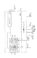
図10は、変換器の例を詳細に示す。図10において、サーバのビデオ、キーボード、マウスポートからのビデオ#1信号とキーボードおよびマウス#1信号は、ポート101および102において変換器100へ入る。変換器100は、オプションとして1×N変換器110(例えば図5を参照して説明したもの)を含むこともできる。この場合、KVM#2、KVM#3…KVM#N信号をX台のサーバと通信し、それら信号をネットワーク20へ提供する。変換器100は、ビデオポート101においてサーバ(例えば図4のサーバ11)からビデオ信号を受け取り、それをビデオ入力回路103へ提供する。ビデオ入力回路103は、増幅器、調節器、その他ビデオインタフェース用関連回路を含む(変更した実施の形態において、変換器100は、サーバ11に内蔵してサーバビデオフレームバッファからビデオ信号を直接受け取ることもできる)。ビデオ入力回路103は、生ビデオデータをサイズ調整解像度回路104へ提供し、前記生ビデオデータをワークステーション(25〜27)が使用するディスプレイに基づくサイズおよび解像度にする。前記ワークステーションは、ネットワーク20から前記生ビデオデータを受け取る。サイズ調整および解像度回路104は、例えば共同所有米国特許第5,917,552号「演繹的制御を利用するビデオ信号インタフェースシステム」(レオーネ)が開示しており、これを参照により組み込む。
【0040】
次に生ビデオデータは、デジタルビデオパケット化回路105においてパケット化する。このデジタルパケット化は、オードリーナ等の米国特許第08/909,924号(1997年8月12日出願)およびオードリーナ等の米国特許第09/100,582号(1998年6月19日出願)に基づき実施でき、これら共同所有特許は参照によりここに組み込む。
【0041】
キーボードおよびマウス信号は、キーボードおよびマウス#1線を経由して変換器ポート102へ入る。前記した通り、キーボードおよびマウス接続は、サーバのマザーボード直接アクセスを提供する。キーボードおよびマウスポート102は、キーボードおよびマウス入出力回路108へ接続する。この入出力回路108は、サーバ11のキーボードおよびマウスポートの入出力信号を扱う。次にキーボードおよびマウス信号は、キーボードおよびマウス変換回路107へ送り、そこで適切な変換を行い、ワークステーションおよびサーバのキーボードおよびマウス信号のフォーマットを確実に整合させる。キーボードおよびマウス信号は、回路106においてパケット化する。
【0042】
さらに変換器100は、ビデオ入出力回路103とキーボードおよびマウス入出力回路108と通信する回路を含み、例えばサーバ起動時にサーバが提供するコマンド命令に応答する。これら命令は、例えばマウスプロトコル、キーボード規格、ディスプレイ解像度等を含むことができる。
【0043】
回路105において生デジタルビデオをパケット化し、回路106においてキーボードおよびマウス信号をパケット化し、これらパケットをネットワークカード109へ送る。ネットワークカード109は、それらパケットをネットワーク20を介して適切なワークステーション25〜27等へ送る。
【0044】
図10は、変換器100のいくつかの回路を省略しているが、これは簡潔のためである。変換器100は、図10に明示していない範囲においては、例えばサイベックス社が販売するオートビューあるいはエックスピーシリーズスイッチ等の従来のKVMスイッチのように動作する。
【0045】
図8は、本発明の他の実施の形態を示す。この実施の形態は、企業ネットワーク10と保守ネットワーク20とを単一ネットワーク80に結合している。図8に示す通り、ワークステーション87および88は、サーバ81,83,85と同様、ネットワーク80と通信し、これらサーバのキーボード、ディスプレイ、マウスを制御できる。サーバ81,83,85がネットワーク80を介して互いに通信する場合、ネットワーク80を介して直接アドレス指定する。ワークステーション87および88は、前記サーバに対し、データを直接アドレス指定することにより、これらサーバと通信できる。しかしながらワークステーション87および88は、サーバ81に対してさらなる制御が必要の場合、変換器82,84,86をアドレス指定し、これら変換器は、キーボード・ビデオ・マウス情報を関連するサーバのマザーボード89,90,91へ直接転送する。
【0046】
図8において、例えばワークステーション87がサーバ83を制御する場合、ワークステーション87は、それ自身のIPアドレスGから変換器84のIPアドレスDに対し、キーボード・ビデオ・マウス情報を送ることにより、変換器84のIPアドレスDにアクセスする。図8の実施の形態は、ネットワーク80上にインターネットプロトコルタイプデータ構造を想定している。もちろん他のデータプロトコルを用いても構わない。ワークステーション87がキーボード・ビデオ・マウスデータを変換器84へ送ると、変換器84は、サーバ83のキーボードおよびマウスポートを介してサーバ83のマザーボード90へのハードウエア接続を有しているため、前記キーボード・マウス情報をマザーボード90へ、そしてビデオ情報をサーバ83のビデオカード(図示せず)へ提供する。
【0047】
図9は、本発明のさらに別の実施の形態を示す。ネットワーク10および保守ネットワーク20は、関連するサーバ93および94を有し、関連する変換器95および96を介して通信する。ワークステーション97は、保守ネットワーク20と通信し、変換器95および96を介してサーバ93および94を制御する。この詳細は前述の通りである。しかしながら図9の実施の形態は、ブリッジ92がネットワーク10と保守ネットワーク20とを接続し、ネットワーク10と保守ネットワーク20とを共通ネットワーク構造に結合している。図9において、保守ネットワーク20は、ネットワーク10から独立している。それでいながらワークステーション97は、ブリッジ92を介してサーバ93およびサーバ94に直接アクセスできる。さらに図9の実施の形態の利点は、ワークステーション97が、変換器95および96を介し、ブリッジ92を使用せず、サーバ93および94のマザーボードに直接アクセスできることである。
【0048】
本発明を特に実施の形態に基づき図示し説明してきたが、当業者には明らかな通り、本発明は、その趣旨および範囲から逸脱することなく、その態様および詳細において様々な変更を許容する。
【図面の簡単な説明】
本発明の前記およびその他目的は、添付図面を参照し現在好適と思われる実施の形態の詳細説明を注意深く検討することにより、完全に理解できるであろう。
【図1】 図1は、従来の企業ネットワークを示す概略図である。
【図2】 図2は、従来のKVMスイッチを示す概略図である。
【図3】 図3は、本発明の好適な実施の形態を示す概略図である。
【図4】 図4は、図3のシステムにおいてインターネットおよびサーバの管理を示す概略図である。
【図5】 図5は、本発明の別の実施の形態を示す概略図である。
【図6】 図6は、KVM−LAN変換を行うカードを示す概略ブロック図である。
【図7】 図7は、本発明に基づくサーバおよび変換器の例を示す概略ブロック図である。
【図8】 図8は、本発明の別の実施の形態を示す概略図である。
【図9】 図9は、本発明のさらに別の実施の形態を示す概略図である。
【図10】 図10は、本発明に基づく変換器の例を示す概略図である。[0001]
1. TECHNICAL FIELD OF THE INVENTION
The present invention relates to a network switching system, and more particularly to a network switching of computer peripheral data.
[0002]
Background and Summary of the Invention
Years ago, when corporate networks began to expand, the so-called KVM (keyboard video mouse) allows a single network operator to access and control several different computers with a single workstation keyboard, display and mouse. ) Demand for switches increased. Initially, the KVM switch provided a function that allowed maintenance operators to access two to eight computers with a single keyboard, display, and mouse. However, as the size of corporate networks increased, so did the complexity of KVM switches. As a result, computer network operators have asked KVM switches for access between one workstation and thousands or tens of thousands of computers. The first response to this is, for example, to expand one KVM switch that provides access to eight servers from one workstation to another eight KVM switches, 8 × 8 = 64 Was to provide access to computers. In this way, a large number of computers can be accessed from a set of keyboard, display, and mouse.
[0003]
Scale-up is a promising option in many computer environments today. However, when it is common to install a very large number of computers in a server farm or the like, the necessity for one network operator to access tens of thousands of computers or more becomes urgent. Of course, it is possible to increase the number of KVM switches and operate a large number of computers with several workstations. However, if the number of KVM switches is increased, there will be a space problem in the server farm.
[0004]
1 and 2 show examples of conventional KVM switches. In FIG. 1, a conventional
[0005]
FIG. 2 illustrates a KVM switch environment. A number of workstations 17-19 communicate with servers A and B of server set 14 via KVM switch 16. Each
[0006]
[0007]
One early type KVM switch is disclosed in US Pat. No. 5,732,212 “Personal computer remote monitoring and operation system and method” by Perholz et al. Perholz discloses remote KVM switching via a telephone network and local switching via a computer daisy chain. Perholz describes how to access a selected computer's motherboard using a host system that communicates with a workstation over a telephone line. In other words, Perholz discloses a method of realizing functions such as reboot and cold boot that would otherwise have to access the motherboard locally by accessing the motherboard using a remote host device.
[0008]
The present invention significantly improves upon conventional KVM switches and remote access KVM switches. The KVM switching provided by the present invention can access any number of servers on the network without using a conventional scaled-up KVM switch or using a conventional remote access device, and the motherboards of these servers Is also accessible. In a conventional network access system, a workstation and a server that communicate via a network exchange keyboard, video, and mouse command data with each other in the form of packet information. For this reason, a conventional remote system such as PC Anywhere, which is commercially available, accesses a server via a telephone network or the Internet, and accesses a keyboard, a display, and a mouse of the server. However, when a user of such a conventional system accesses, for example, many servers existing on a corporate LAN or the Internet, the user cannot access the motherboards of these servers. In other words, conventional users only have to select a conventional KVM switch that provides motherboard access, which is limited in size, or a remote access switch that can access many servers but cannot directly access the motherboard. It was.
[0009]
The present invention solves these problems and allows a relatively simple structure to be accessed from any number of workstations and any number of server keyboards, displays, and mice in a network such as a corporate network or the Internet. To do. In the preferred embodiment of the present invention, multiple servers communicate over a corporate network. The keyboard, video and mouse ports of each of these servers are connected to the corresponding converter box via cables. These converter boxes communicate with a maintenance network that communicates with a number of user workstations. In this embodiment, when one user of the workstation accesses one of the servers, the user workstation communicates with the converter box corresponding to the server via the maintenance network, and Gain motherboard access to the server. The user can then use the server to communicate with other servers via the corporate network.
[0010]
In this specification, when referring to the converter “core” and / or “unit”, the converter does not necessarily need to be a “box” or “unit”, and can be built in a computer card, a server card, or a system component. Elements may be used.
[0011]
In a preferred embodiment of the present invention, any number of users can communicate on the maintenance network, any number of servers can communicate on the corporate network, any user can communicate with any server, and all servers communicate with each other. It does not require a conventional scaled-up KVM switch, and does not require a conventional KVM remote access device, thereby realizing complete access to the motherboard. Thus, the preferred embodiment provides basically unlimited scalability and allows each user to access any server motherboard.
[0012]
In other embodiments, by using a security procedure, motherboard access for a specific or all servers can be limited to specific or all workstations.
[0013]
In another embodiment, the corporate network and the maintenance network may be a common network, not a network independent of each other.
[0014]
In yet another embodiment, the converter is not assigned to each server separately, but can operate on one or more servers.
[0015]
In yet another embodiment, the maintenance network and enterprise network can be interconnected.
[0016]
BEST MODE FOR CARRYING OUT THE INVENTION
FIG. 3 shows servers 11 to 13 that communicate with each other in the
[0017]
In accordance with the present invention,
[0018]
FIG. 3 shows three servers, three workstations, and two networks, but the present invention is not limited to the specific embodiment shown in FIG. More or less. By using the independent converter units 21 to 23, a commercially available server can be used as it is as the servers 11 to 13. However, the converters 21 to 23 may be incorporated in the servers 11 to 13 as computer plug-in cards, for example.
[0019]
The
[0020]
In one embodiment, the converter 21 may be a modified known KVM switch so that the KVM signal can be converted into a LAN protocol. An example of such a known switch is described in Pinkston US patent application Ser. No. 09 / 379,576, which is incorporated herein by reference. The converter 21 is connected to, for example, the server 11 so that the conventional KVM switch of FIG. 2 is connected to the personal computer. That is, the converter 21 is connected to the keyboard, video, and mouse port of the server 11 via a cable to realize direct access to the motherboard of the server 11 from the converter 21, and the selected one of the
[0021]
User workstations 25-27 communicate with converters 21-23 via
[0022]
When a user workstation, such as
[0023]
In the opposite direction, the converter packetizes the digital video data from the
[0024]
In the previous paragraph, the explanation has been made for one direction, but the
[0025]
Converters 21-23 perform any necessary mediation steps for workstations 25-27 to communicate with any of servers 11-13. That is, the converters 21 to 23 respond to the activation of the servers 11 to 13 and provide initial responses of the appropriate keyboard, display, and mouse required by the servers 11 to 13, as if the appropriate keyboard, display, Make them believe that the mouse is connected.
[0026]
As is apparent from FIG. 3, any number of workstations 25-27 (limited only by the number that the
[0027]
The
[0028]
FIG. 4 is a diagram in which
[0029]
Further, FIG. 4 shows a
[0030]
FIG. 5 shows an embodiment obtained by modifying the embodiment of FIG. In FIG. 5, the
[0031]
A schematic configuration of the server and the converter will be described with reference to FIG. In FIG. 7, the
[0032]
Furthermore, the converter 47 communicates with the
[0033]
As shown in FIG. 7, the converter 47 mediates between the workstation 51 that communicates with the converter 47 via the
[0034]
Accordingly, the present invention is substantially different from conventional remote access devices that communicate with a server via a server network card, server modem, or the like. This is because the conventional system cannot achieve direct access to the motherboard, whereas the computer of the present invention can do so via the server keyboard and mouse port.
[0035]
As shown in FIG. 7, the
[0036]
The conversion function of the converter 47 may be built in the
[0037]
Furthermore, the present invention is different from the conventional server card 36 (FIG. 6). This conventional product receives keyboard and mouse commands 39 and video commands 40, converts these commands into network packets, and sends them to the network 35. As shown in FIG. 6, some conventional systems receive keyboard and
[0038]
The converter 47 receives the raw video data at the
[0039]
FIG. 10 shows an example of a transducer in detail. In FIG. 10, the video # 1 signal from the server video, keyboard and mouse ports and the keyboard and mouse # 1 signal enter the
[0040]
Next, the raw video data is packetized by the digital
[0041]
Keyboard and mouse signals enter the
[0042]
Further, the
[0043]
The
[0044]
FIG. 10 omits some of the circuitry of
[0045]
FIG. 8 shows another embodiment of the present invention. In this embodiment, the
[0046]
In FIG. 8, for example, when the
[0047]
FIG. 9 shows yet another embodiment of the present invention.
[0048]
While the invention has been particularly shown and described with reference to the embodiments thereof, it will be apparent to those skilled in the art that the invention is susceptible to various modifications in form and detail without departing from the spirit and scope thereof.
[Brief description of the drawings]
The foregoing and other objects of the invention will be more fully understood by careful consideration of the detailed description of the presently preferred embodiments with reference to the accompanying drawings.
FIG. 1 is a schematic diagram showing a conventional corporate network.
FIG. 2 is a schematic diagram showing a conventional KVM switch.
FIG. 3 is a schematic diagram showing a preferred embodiment of the present invention.
FIG. 4 is a schematic diagram illustrating management of the Internet and servers in the system of FIG.
FIG. 5 is a schematic diagram showing another embodiment of the present invention.
FIG. 6 is a schematic block diagram illustrating a card that performs KVM-LAN conversion.
FIG. 7 is a schematic block diagram illustrating an example of a server and a converter according to the present invention.
FIG. 8 is a schematic view showing another embodiment of the present invention.
FIG. 9 is a schematic view showing still another embodiment of the present invention.
FIG. 10 is a schematic diagram illustrating an example of a transducer according to the present invention.
Claims (27)
パケットスイッチネットワーク(80)によって接続され、パケットスイッチネットワーク(80)上でお互いの間で通信可能な複数のサーバ(81;83;85)と、
パケットスイッチネットワーク(80)によって接続された少なくとも1台のワークステーション(87;88)と、を含み、
変換器(82;84;86)は、
選択されたサーバ(81;83;85)の標準装置ポートに接続され、装置インタフェース(46)と装置ポートを介して選択されたサーバ(81;83;85)のマザーボード(89;90;91)への直接アクセスを提供する装置インタフェース(46)であって、選択されたサーバの前記標準装置ポートはサーバネットワークインターフェースとは異なるものと、
パケットスイッチネットワーク(80)へのネットワークアクセスを提供する変換器ネットワークインタフェースであって、変換器ネットワークインタフェースは装置インタフェース(46)およびサーバネットワークインターフェースとは異なるものと、
選択されたサーバ(81;83;85)とパケットスイッチネットワーク(80)上のワークステンション(87;88)との間で双方向データ通信を行うため、1)変換器ネットワークインタフェースを宛先とした入力データをパケットスイッチネットワーク(80)から取り出し、その入力データを選択されたサーバ(81;83;85)に適した標準装置プロトコルに基づき装置インタフェース(46)へ送り、2)データの宛先をパケットスイッチネットワーク(80)上のワークステーション(87;88)にして、出力データを、装置インタフェース(46)からパケットスイッチネットワーク(80)へ、パケットスイッチネットワークプロトコルに基づき送り出すデータ変換器とを備える、変換器システム。 Alternate data path between one workstation (87; 88) on the same packet switch network (80) as one selected server (81; 83; 85) in a multi-server packet switch network (80) a transducer system for providing the selected server (81; 83; 85) is the work station; has a corresponding server network interface for communicating with (87 88), the system ,
A plurality of servers (81; 83; 85) connected by the packet switch network (80) and capable of communicating with each other on the packet switch network (80);
At least one workstation (87; 88) connected by a packet switch network (80);
The transducer (82; 84; 86)
Selected server motherboard (85 81; 83) is connected to the standard device port (81; 83 85), selected via the the device port device interface (46) the server (89; 90; 91) A device interface (46) that provides direct access to the server, wherein the standard device port of the selected server is different from the server network interface ;
A converter network interface providing network access to the packet switch network (80) , the converter network interface being different from the device interface (46) and the server network interface ;
To perform two-way data communication between the selected server (81; 83; 85) and the work station (87; 88) on the packet switch network (80) , 1) Input destined for the converter network interface extracts data from the packet switched network (80), the input data the selected server based on the standard device protocol suited for (81; 83 85) device sends to the interface (46), 2) the packet switch a destination of data workstations on the network (80); in the (87 88), the output data from the device interface (46) to the packet switched network (80), and a data converter for feeding based on a packet switched network protocol, converter System .
前記装置インタフェース(46)は、多数のサーバ(81;83;85)の各々の標準装置ポートと接続し、前記装置インタフェース(46)とそれぞれの装置ポートとを介して多数のサーバ(81;83;85)の各サーバのマザーボード(89;90;91)への直接アクセスを提供し、
前記データ変換器は、パケットスイッチネットワーク(80)上の多数のサーバ(81;83;85)のいずれかとワークステーション(87;88)との間で双方向データ通信を行うため、1)多数のサーバ(81;83;85)の選択されたサーバ(81;83;85)を宛先とするネットワークからの入力データを取り出し、前記選択されたサーバ(81;83;85)に適した標準装置プロトコルに基づき前記入力データを前記装置インタフェース(46)および選択されたサーバ(81;83;85)のための対応する装置ポートへ送り、2)出力データの宛先をパケットスイッチネットワーク(80)上のワークステーション(87;88)にして、出力データを、多数のサーバ(81;83;85)のいずれかのサーバ(81;83;85)から前記装置インタフェース(46)を介してパケットスイッチネットワークプロトコルに基づき送り出す、請求項1記載のシステム。Said transducer (82; 84; 86), the workstation linked operably to; (85 81; 83), (87 88) Server large number of the packet switch network (80)
The device interface (46), large number of servers connected to each of the standard device port (81; 83 85), wherein the device interface (46) and the respective device ports and multiple server via (81; 83; 85) providing direct access to the motherboard (89; 90; 91 ) of each server ;
Wherein the data converter, large number of servers on the packet switched network (80) and one (81; 85; 83) work station; for two-way data communication with the (87 88), 1) Multi the number of servers (81; 83; 85) selected server (81; 83 85) the input data is removed from the network to the destination, the selected server suitable (81; 83 85) standard the device interfacing the input data based on the device protocol (46) and selected server (81; 83; 85) corresponding feeding to the device ports for, 2) a packet switch network destination of the output data (80) on workstation (87; 88) to the to the output data, a large number of servers or server (81; 83 85) (81 83; 85) feeding on the basis of a packet switch network protocol via the device interface (46) from the system of claim 1, wherein.
選択されたサーバ(81;83;85)のキーボードポートに接続し、キーボードインタフェースおよびキーボードポートを介して選択されたサーバ(81;83;85)のマザーボードへの直接アクセスを提供するキーボードインタフェースと、
前記サーバ(81;83;85)のマウスポートに接続し、マウスインタフェースおよびマウスポートを介して選択されたサーバ(81;83;85)のマザーボードへの直接アクセスを提供するマウスインタフェースと、
選択されたサーバ(81;83;85)のビデオ装置ポート(44)に接続し、選択されたサーバ(81;83;85)のビデオプロセッサとのインタフェースを行うビデオインタフェース(45)と、を備える、請求項1記載のシステム。 The device interface (46) is
A keyboard interface that provides direct access to the motherboard (85 81; 83), selected server (81; 83 85) connected to the keyboard port of a keyboard interface and the selected server through the keyboard port
And mouse interfaces that provide direct access to the motherboard (85 81; 83), mice were connected to the port, the server selected via the mouse interface and mouse port (85 81; 83) said server
Selected server comprises a video interface (45) that interfaces with the video processor (85 81; 83) connected to a video device port (81; 83 85) (44), selected server The system of claim 1 .
キーボードインタフェースを介して前記サーバのキーボードポートに接続し、前記キーボードインタフェースと前記キーボードポートとを介して前記サーバのマザーボードへの直接アクセスを提供し、
マウスインタフェースを介して前記サーバのマウスポートに接続し、前記マウスインタフェースと前記マウスポートとを介して前記サーバのマザーボードへの直接アクセスを提供し、
ビデオインタフェースを介して前記サーバのビデオポートに接続し、前記サーバのビデオプロセッサとのインタフェースを行い、
第一のパケットスイッチネットワークインタフェースを使ってパケットスイッチネットワークを介して前記キーボード・ビデオ・マウスワークステーションへのネットワークアクセスを提供し、
パケットスイッチネットワークを介して前記サーバと前記キーボード・ビデオ・マウスワークステーションとの間におけるキーボード・ビデオ・マウス情報の双方向通信を、(1)データ変換器を介しておよび(2)データ変換器を通ることなしに、選択的に行い、前記データ変換器は、前記キーボード・ビデオ・マウス情報が前記データ変換器を通るときには、第2のパケットスイッチネットワークインタフェースを介してパケットスイッチネットワークとの間において前記キーボード・ビデオ・マウス情報をローカルパケットスイッチネットワークプロトコルに基づき通信し、前記キーボード、マウス、およびビデオインタフェースの対応するものとの間において前記キーボード・ビデオ・マウス情報を前記サーバに適したキーボード、マウス、およびビデオプロトコルに基づき通信する、ステップを含んだ方法。A method of linking a server in a packet switch network of a plurality of servers to a keyboard, video and mouse workstation in the packet switch network,
Connected to the server's keyboard port via a keyboard interface, providing direct access to the server's motherboard via the keyboard interface and the keyboard port;
Connected to the mouse port of the server via a mouse interface, providing direct access to the motherboard of the server via the mouse interface and the mouse port;
Connect to the video port of the server via a video interface, interface with the video processor of the server,
Providing network access to the keyboard / video / mouse workstation via a packet switch network using a first packet switch network interface;
Two-way communication of keyboard / video / mouse information between the server and the keyboard / video / mouse workstation via a packet switch network (1) via a data converter and (2) a data converter The data converter is selectively connected to the packet switch network via a second packet switch network interface when the keyboard / video / mouse information passes through the data converter. keyboard video mouse information communication and based on the local packet switch network protocol, keyboard the keyboard, mouse, and video interfaces the keyboard video mouse information between a corresponding one suitable for the server, Mouse, and it communicates on the basis of video protocols, including the step method.
Applications Claiming Priority (3)
| Application Number | Priority Date | Filing Date | Title |
|---|---|---|---|
| US09/563,434 US6681250B1 (en) | 2000-05-03 | 2000-05-03 | Network based KVM switching system |
| US09/563,434 | 2000-05-03 | ||
| PCT/US2000/016972 WO2001084291A1 (en) | 2000-05-03 | 2000-06-21 | Network based kvm switching system |
Publications (2)
| Publication Number | Publication Date |
|---|---|
| JP2003534685A JP2003534685A (en) | 2003-11-18 |
| JP4583695B2 true JP4583695B2 (en) | 2010-11-17 |
Family
ID=24250475
Family Applications (1)
| Application Number | Title | Priority Date | Filing Date |
|---|---|---|---|
| JP2001580647A Expired - Lifetime JP4583695B2 (en) | 2000-05-03 | 2000-06-21 | Keyboard / video / mouse switching system via network |
Country Status (14)
| Country | Link |
|---|---|
| US (2) | US6681250B1 (en) |
| EP (1) | EP1297408B1 (en) |
| JP (1) | JP4583695B2 (en) |
| CN (1) | CN100349099C (en) |
| AT (1) | ATE444514T1 (en) |
| AU (2) | AU2000258803B2 (en) |
| CA (1) | CA2409057C (en) |
| DE (1) | DE60043077D1 (en) |
| IL (2) | IL152604A0 (en) |
| MY (1) | MY126112A (en) |
| NZ (1) | NZ522395A (en) |
| RU (1) | RU2249847C2 (en) |
| TW (1) | TW522329B (en) |
| WO (1) | WO2001084291A1 (en) |
Families Citing this family (151)
| Publication number | Priority date | Publication date | Assignee | Title |
|---|---|---|---|---|
| US8206379B2 (en) * | 2001-02-02 | 2012-06-26 | Homer Gregg S | Techniques for alteration of iris pigment |
| US7424551B2 (en) * | 2001-03-29 | 2008-09-09 | Avocent Corporation | Passive video multiplexing method and apparatus priority to prior provisional application |
| US20020147814A1 (en) * | 2001-04-05 | 2002-10-10 | Gur Kimchi | Multimedia devices over IP |
| US7293075B2 (en) * | 2001-04-12 | 2007-11-06 | Unisys Corporation | Method and apparatus for operating a data processing system using multiple console views |
| US6957287B2 (en) * | 2001-11-09 | 2005-10-18 | Aten International Co., Ltd. | Asynchronous/synchronous KVMP switch for console and peripheral devices |
| US8176226B2 (en) * | 2001-11-09 | 2012-05-08 | Aten International Co., Ltd. | KVMP switch allowing asynchronous and synchronous switching for console devices and peripheral devices among different computers |
| US6825846B2 (en) | 2001-12-10 | 2004-11-30 | American Megatrends, Inc. | Systems and methods for capturing screen displays from a host computing system for display at a remote terminal |
| US20030196125A1 (en) * | 2002-03-28 | 2003-10-16 | Compaq Information Technologies Group, L.P. | Method of powering on and off a computer using a standard keyboard |
| SE525304C2 (en) * | 2002-04-22 | 2005-01-25 | Snalle Ab | Method and apparatus for controlling access between a computer and a communication network |
| US7684483B2 (en) * | 2002-08-29 | 2010-03-23 | Raritan Americas, Inc. | Method and apparatus for digitizing and compressing remote video signals |
| US8558795B2 (en) * | 2004-03-12 | 2013-10-15 | Riip, Inc. | Switchless KVM network with wireless technology |
| US7818480B2 (en) * | 2002-08-29 | 2010-10-19 | Raritan Americas, Inc. | Wireless management of remote devices |
| US8068546B2 (en) * | 2002-08-29 | 2011-11-29 | Riip, Inc. | Method and apparatus for transmitting video signals |
| US7260624B2 (en) * | 2002-09-20 | 2007-08-21 | American Megatrends, Inc. | Systems and methods for establishing interaction between a local computer and a remote computer |
| JP4601895B2 (en) * | 2002-09-26 | 2010-12-22 | 富士通コンポーネント株式会社 | Switching device and computer system |
| US20040093391A1 (en) * | 2002-11-07 | 2004-05-13 | Heng-Chien Chen | Computer console for wirelessly controlling remote computers |
| US7454785B2 (en) * | 2002-12-19 | 2008-11-18 | Avocent Huntsville Corporation | Proxy method and system for secure wireless administration of managed entities |
| US7284278B2 (en) * | 2003-03-04 | 2007-10-16 | Dell Products L.P. | Secured KVM switch |
| US7559092B2 (en) * | 2003-03-04 | 2009-07-07 | Dell Products L.P. | Secured KVM switch |
| US7418141B2 (en) * | 2003-03-31 | 2008-08-26 | American Megatrends, Inc. | Method, apparatus, and computer-readable medium for identifying character coordinates |
| US7512704B2 (en) * | 2003-04-03 | 2009-03-31 | Avocent Corporation | Wireless computer system |
| TWI224273B (en) * | 2003-04-10 | 2004-11-21 | Inventec Corp | Switching system for operation priority of I/O unit and method thereof |
| CN1308872C (en) * | 2003-04-18 | 2007-04-04 | 英业达股份有限公司 | Switchover system of outgut input element use right and method |
| US6915362B2 (en) * | 2003-04-25 | 2005-07-05 | Dell Products L.P. | System to aggregate keyboard video mouse (KVM) control across multiple server blade chassis |
| US7394761B2 (en) * | 2003-04-29 | 2008-07-01 | Avocent Huntsville Corporation | System and method for delivering messages using alternate modes of communication |
| US7412625B2 (en) * | 2003-05-27 | 2008-08-12 | American Megatrends, Inc. | Method and system for remote software debugging |
| WO2005004490A2 (en) * | 2003-06-13 | 2005-01-13 | Lumexis Corporation | Remote interface optical network |
| US7546584B2 (en) * | 2003-06-16 | 2009-06-09 | American Megatrends, Inc. | Method and system for remote software testing |
| CN1297914C (en) * | 2003-06-19 | 2007-01-31 | 联想(北京)有限公司 | Signal manager of mouse, keyboard and display applied to cluster |
| US7543277B1 (en) | 2003-06-27 | 2009-06-02 | American Megatrends, Inc. | Method and system for remote software debugging |
| US20050052465A1 (en) * | 2003-07-03 | 2005-03-10 | Moore Richard L. | Wireless keyboard, video, mouse device |
| JP4342862B2 (en) * | 2003-07-23 | 2009-10-14 | 富士通コンポーネント株式会社 | Signal processing apparatus, remote control system, signal processing method and program thereof |
| US7925722B1 (en) * | 2003-08-01 | 2011-04-12 | Avocent Corporation | Method and apparatus for discovery and installation of network devices through a network |
| US7454495B2 (en) * | 2003-09-18 | 2008-11-18 | Raritan America, Inc. | Intelligent modular server management system for selectively operating and locating a plurality of computers |
| US7475322B2 (en) * | 2003-11-14 | 2009-01-06 | Avocent Huntsville Corporation | Wireless broadcast protocol |
| JP4490077B2 (en) * | 2003-11-14 | 2010-06-23 | 富士通コンポーネント株式会社 | Server system, signal processing apparatus thereof, server thereof, and casing thereof |
| US8176155B2 (en) | 2003-11-26 | 2012-05-08 | Riip, Inc. | Remote network management system |
| US8683024B2 (en) | 2003-11-26 | 2014-03-25 | Riip, Inc. | System for video digitization and image correction for use with a computer management system |
| US7114018B1 (en) * | 2004-01-06 | 2006-09-26 | American Megatrends, Inc. | Methods, systems, and computer program products for communication of non-keyboard related data via a keyboard connection |
| JP4535314B2 (en) * | 2004-02-18 | 2010-09-01 | 富士通コンポーネント株式会社 | Information processing apparatus, system, remote operation method, program, and recording medium |
| US7827258B1 (en) * | 2004-03-01 | 2010-11-02 | American Megatrends, Inc. | Method, system, and apparatus for communicating with a computer management device |
| TWI237762B (en) * | 2004-03-05 | 2005-08-11 | Aten Int Co Ltd | Keyboard video mouse switch and the method thereof |
| US7853663B2 (en) * | 2004-03-12 | 2010-12-14 | Riip, Inc. | Wireless management system for control of remote devices |
| CN1310117C (en) * | 2004-04-02 | 2007-04-11 | 宏正自动科技股份有限公司 | Computer change-over switch and method thereof |
| DE102004017843B4 (en) * | 2004-04-13 | 2007-04-05 | Aten International Co., Ltd. | Multi-way keyboard-to-screen mouse switch and method therefor |
| US7415552B2 (en) | 2004-04-15 | 2008-08-19 | Aten International Co., Ltd | Keyboard video mouse switch for multiple chaining and the method thereof |
| US7613854B2 (en) | 2004-04-15 | 2009-11-03 | Aten International Co., Ltd | Keyboard video mouse (KVM) switch wherein peripherals having source communication protocol are routed via KVM switch and converted to destination communication protocol |
| DE102004019107B4 (en) * | 2004-04-20 | 2006-12-28 | Aten International Co., Ltd. | Keyboard screen mouse switch and a method for this |
| TWI273415B (en) | 2004-05-13 | 2007-02-11 | Aten Int Co Ltd | Control apparatus for controlling a plurality of computers and direct signal collecting device thereof |
| US7730152B2 (en) * | 2004-06-28 | 2010-06-01 | Broadcom Corporation | Wireless input control of multiple computing devices |
| US8069239B2 (en) * | 2004-07-20 | 2011-11-29 | Beckman Coulter, Inc. | Centralized monitor and control system for laboratory instruments |
| US7519749B1 (en) | 2004-08-25 | 2009-04-14 | American Megatrends, Inc. | Redirecting input and output for multiple computers |
| TWI253586B (en) * | 2004-09-01 | 2006-04-21 | Aten Int Co Ltd | Control system for controlling a plurality of computers |
| CN1324435C (en) * | 2004-10-20 | 2007-07-04 | 英业达股份有限公司 | Online switching interface for multitask type computer peripheral equipment |
| US7347271B2 (en) | 2004-10-27 | 2008-03-25 | Schlumberger Technology Corporation | Wireless communications associated with a wellbore |
| US7477160B2 (en) | 2004-10-27 | 2009-01-13 | Schlumberger Technology Corporation | Wireless communications associated with a wellbore |
| US7613927B2 (en) * | 2004-11-12 | 2009-11-03 | Raritan Americas, Inc. | System for providing secure access to KVM switch and other server management systems |
| US7624281B2 (en) * | 2004-12-07 | 2009-11-24 | Video Products, Inc. | System and method for providing access to a keyboard video and mouse drawer using biometric authentication |
| US20060236347A1 (en) * | 2005-03-24 | 2006-10-19 | Jayson Holovacs | Digital remote device management system for selectively operating a plurality of remote devices |
| US7586935B2 (en) * | 2005-03-25 | 2009-09-08 | Aten International Co., Ltd. | KVM switch with an integrated network hub |
| US8332523B2 (en) * | 2005-04-06 | 2012-12-11 | Raritan Americas, Inc. | Architecture to enable keyboard, video and mouse (KVM) access to a target from a remote client |
| US8516171B2 (en) * | 2005-04-06 | 2013-08-20 | Raritan Americas Inc. | Scalable, multichannel remote device KVM management system for converting received signals into format suitable for transmission over a command network |
| US7640382B2 (en) | 2005-04-29 | 2009-12-29 | Avocent Corporation | Virtual media systems, methods and devices |
| US7966402B2 (en) * | 2005-06-28 | 2011-06-21 | Hewlett-Packard Development Company, L.P. | Switch to selectively couple any of a plurality of video modules to any of a plurality of blades |
| US7634076B2 (en) * | 2005-08-03 | 2009-12-15 | Indicium Media, Llc | Network, system and method for distributing digital media |
| US7546374B2 (en) * | 2005-08-05 | 2009-06-09 | Global Serv Inc. | Methods and arrangements for managing and maintaining a switch environment |
| US7689704B2 (en) * | 2005-08-05 | 2010-03-30 | Global Serv Inc. | Methods and arrangements for managing automated switching |
| US7886091B2 (en) * | 2005-08-05 | 2011-02-08 | Global Serv Inc. | Methods and arrangements for performing desktop switching |
| US20070058657A1 (en) * | 2005-08-22 | 2007-03-15 | Graham Holt | System for consolidating and securing access to all out-of-band interfaces in computer, telecommunication, and networking equipment, regardless of the interface type |
| CN101268640B (en) * | 2005-09-19 | 2015-05-20 | 路美克斯公司 | Fiber-to-the-seat in-flight entertainment system |
| US8478884B2 (en) * | 2005-09-30 | 2013-07-02 | Riip, Inc. | Wireless remote device management utilizing mesh topology |
| US7752339B2 (en) * | 2005-10-11 | 2010-07-06 | Aten International Co., Ltd. | Matrix architecture for KVM extenders |
| CN100447714C (en) * | 2005-11-04 | 2008-12-31 | 英业达股份有限公司 | Online switching interfaces of peripheral devices in multitask mode computer |
| US8010843B2 (en) * | 2005-12-14 | 2011-08-30 | American Megatrends, Inc. | System and method for debugging a target computer using SMBus |
| US7423642B2 (en) * | 2005-12-14 | 2008-09-09 | Winbond Electronics Corporation | Efficient video frame capturing |
| US7689677B2 (en) * | 2006-02-17 | 2010-03-30 | Avocent Huntsville Corporation | Dynamic power cycling |
| US7555570B2 (en) * | 2006-02-17 | 2009-06-30 | Avocent Huntsville Corporation | Device and method for configuring a target device |
| US20070208891A1 (en) * | 2006-03-01 | 2007-09-06 | Aten International Co., Ltd | KVM switching system |
| US7852873B2 (en) * | 2006-03-01 | 2010-12-14 | Lantronix, Inc. | Universal computer management interface |
| US7428606B2 (en) * | 2006-05-05 | 2008-09-23 | Dell Prodcuts L.P. | Method, system and apparatus to allow users to remotely mount USB devices and access KVM through a server interface pod (SIP) |
| US9198084B2 (en) | 2006-05-26 | 2015-11-24 | Qualcomm Incorporated | Wireless architecture for a traditional wire-based protocol |
| US20080002894A1 (en) * | 2006-06-29 | 2008-01-03 | Winbond Electronics Corporation | Signature-based video redirection |
| WO2008097273A1 (en) * | 2006-08-10 | 2008-08-14 | Avocent Huntsville Corporation | Usb based virtual media system |
| US20080040527A1 (en) * | 2006-08-14 | 2008-02-14 | Filipov Metodi N | Management module |
| US7783799B1 (en) | 2006-08-31 | 2010-08-24 | American Megatrends, Inc. | Remotely controllable switch and testing methods using same |
| WO2008033870A2 (en) * | 2006-09-11 | 2008-03-20 | Lumexis Corporation | Fiber-to-the-seat (ftts) fiber distribution system |
| JP4884155B2 (en) * | 2006-10-04 | 2012-02-29 | 富士通コンポーネント株式会社 | Starting device |
| US20080184320A1 (en) * | 2007-01-25 | 2008-07-31 | Tony Lou | TVOD Processing Device And Computer KVM Switch Thereof |
| US8838856B2 (en) * | 2007-02-16 | 2014-09-16 | Emulex Corporation | Virtual universal asynchronous receiver transmitter for server systems |
| US8375115B2 (en) * | 2007-02-16 | 2013-02-12 | Emulex Corporation | Methods, apparatus, and systems for integrated management, graphics and I/O control of server systems |
| US9024878B2 (en) * | 2007-02-16 | 2015-05-05 | Emulex Corporation | Hardware cursor snooping |
| US8144160B2 (en) * | 2007-02-16 | 2012-03-27 | Emulex Corporation | Methods and apparatus for non-intrusive capturing of frame buffer memory information for remote display |
| US20080273113A1 (en) * | 2007-05-02 | 2008-11-06 | Windbond Electronics Corporation | Integrated graphics and KVM system |
| US20080313319A1 (en) * | 2007-06-18 | 2008-12-18 | Avocent Huntsville Corporation | System and method for providing multi-protocol access to remote computers |
| US8667144B2 (en) | 2007-07-25 | 2014-03-04 | Qualcomm Incorporated | Wireless architecture for traditional wire based protocol |
| JP5127366B2 (en) | 2007-08-29 | 2013-01-23 | 富士通コンポーネント株式会社 | Information processing apparatus, KVM switch, server, and control program |
| US20090077428A1 (en) * | 2007-09-14 | 2009-03-19 | Softkvm Llc | Software Method And System For Controlling And Observing Computer Networking Devices |
| JP5008007B2 (en) | 2007-11-21 | 2012-08-22 | 富士通コンポーネント株式会社 | Information processing apparatus, remote system, program, and computer-readable recording medium |
| DE102007059173A1 (en) * | 2007-12-06 | 2009-06-10 | Desch, Jürgen, Dipl.-Architekt | Computer e.g. personal computer, has storage device i.e. flash memory, provided for storing and/or transporting information, switching unit switching between computing units, and operating units i.e. processing unit, processing information |
| US20090157921A1 (en) * | 2007-12-12 | 2009-06-18 | Aten International Co., Ltd. | Kvm management system and method |
| JP5094377B2 (en) | 2007-12-28 | 2012-12-12 | 富士通コンポーネント株式会社 | KVM switch and remote system |
| JP2009176255A (en) * | 2008-01-28 | 2009-08-06 | Fujitsu Component Ltd | Multi-user kvm switch |
| JP5197040B2 (en) * | 2008-02-01 | 2013-05-15 | 富士通コンポーネント株式会社 | KVM switch and program |
| US8811294B2 (en) | 2008-04-04 | 2014-08-19 | Qualcomm Incorporated | Apparatus and methods for establishing client-host associations within a wireless network |
| JP2009252172A (en) | 2008-04-10 | 2009-10-29 | Fujitsu Component Ltd | Remote operation system |
| JP4627554B2 (en) * | 2008-07-25 | 2011-02-09 | 富士通コンポーネント株式会社 | Switch, computer system, mouse coordinate conversion method, and mouse coordinate conversion program |
| JP5074326B2 (en) | 2008-08-19 | 2012-11-14 | 富士通コンポーネント株式会社 | Information processing apparatus, KVM switch, remote system and program |
| CN102177682A (en) * | 2008-10-07 | 2011-09-07 | 惠普开发有限公司 | Portable management device |
| US7930447B2 (en) * | 2008-10-17 | 2011-04-19 | International Business Machines Corporation | Listing windows of active applications of computing devices sharing a keyboard based upon requests for attention |
| US9398089B2 (en) | 2008-12-11 | 2016-07-19 | Qualcomm Incorporated | Dynamic resource sharing among multiple wireless devices |
| US9378703B2 (en) | 2009-01-30 | 2016-06-28 | Fujitsu Component Limited | KVM switch and computer readable medium |
| US8473651B1 (en) | 2009-04-29 | 2013-06-25 | Clisertec Corporation | Isolated protected access device |
| JP4535346B2 (en) * | 2009-06-18 | 2010-09-01 | 富士通コンポーネント株式会社 | Information processing apparatus, system, remote operation method, program, and recording medium |
| US9264248B2 (en) | 2009-07-02 | 2016-02-16 | Qualcomm Incorporated | System and method for avoiding and resolving conflicts in a wireless mobile display digital interface multicast environment |
| EP2462513B1 (en) | 2009-08-06 | 2018-12-19 | Global Eagle Entertainment Inc. | Serial networking fiber-to-the-seat inflight entertainment system |
| WO2011020071A1 (en) * | 2009-08-14 | 2011-02-17 | Lumexis Corp. | Video display unit docking assembly for fiber-to-the-screen inflight entertainment system |
| JP5318699B2 (en) * | 2009-08-17 | 2013-10-16 | 富士通コンポーネント株式会社 | KVM switch, KVM system and program |
| US8416698B2 (en) * | 2009-08-20 | 2013-04-09 | Lumexis Corporation | Serial networking fiber optic inflight entertainment system network configuration |
| EP2486728A4 (en) * | 2009-10-05 | 2015-10-21 | Lumexis Corp | Inflight communication system |
| US9582238B2 (en) | 2009-12-14 | 2017-02-28 | Qualcomm Incorporated | Decomposed multi-stream (DMS) techniques for video display systems |
| US8862697B2 (en) * | 2009-12-31 | 2014-10-14 | Aten International Co., Ltd. | Intelligent network management platform for IKVM servers |
| CN102411429A (en) * | 2010-09-17 | 2012-04-11 | 宏正自动科技股份有限公司 | Data-processing method and network-type keyboard-video-mouse (KVM) system and device applying same |
| US9787725B2 (en) | 2011-01-21 | 2017-10-10 | Qualcomm Incorporated | User input back channel for wireless displays |
| US8964783B2 (en) | 2011-01-21 | 2015-02-24 | Qualcomm Incorporated | User input back channel for wireless displays |
| US9413803B2 (en) | 2011-01-21 | 2016-08-09 | Qualcomm Incorporated | User input back channel for wireless displays |
| JP2014508995A (en) * | 2011-01-21 | 2014-04-10 | クゥアルコム・インコーポレイテッド | User input back channel for wireless display |
| US10135900B2 (en) | 2011-01-21 | 2018-11-20 | Qualcomm Incorporated | User input back channel for wireless displays |
| US9582239B2 (en) | 2011-01-21 | 2017-02-28 | Qualcomm Incorporated | User input back channel for wireless displays |
| US9065876B2 (en) | 2011-01-21 | 2015-06-23 | Qualcomm Incorporated | User input back channel from a wireless sink device to a wireless source device for multi-touch gesture wireless displays |
| US8674957B2 (en) | 2011-02-04 | 2014-03-18 | Qualcomm Incorporated | User input device for wireless back channel |
| US9503771B2 (en) | 2011-02-04 | 2016-11-22 | Qualcomm Incorporated | Low latency wireless display for graphics |
| US10108386B2 (en) | 2011-02-04 | 2018-10-23 | Qualcomm Incorporated | Content provisioning for wireless back channel |
| US10042656B2 (en) | 2011-08-01 | 2018-08-07 | Avocent Corporation | System and method for providing migrateable virtual serial port services |
| US9525998B2 (en) | 2012-01-06 | 2016-12-20 | Qualcomm Incorporated | Wireless display with multiscreen service |
| CN102708002B (en) * | 2012-05-15 | 2015-03-04 | 曙光信息产业(北京)有限公司 | Display management method of video card in baseboard management controller (BMC) s, and server |
| US9313602B2 (en) | 2012-10-24 | 2016-04-12 | Beta Brain, Inc. | Remotely accessing a computer system |
| TWI616808B (en) * | 2014-06-30 | 2018-03-01 | 緯創資通股份有限公司 | Method and apparatus for sharing display frame |
| TWI556112B (en) * | 2015-07-24 | 2016-11-01 | 鋒厚科技股份有限公司 | Switching device |
| US10657075B2 (en) * | 2016-10-11 | 2020-05-19 | I/O Interconnect, Ltd. | Keyboard-video-mouse switch, and signal transmitting method |
| US10467169B2 (en) | 2016-10-11 | 2019-11-05 | I/O Interconnect, Ltd. | Human interface device switch with security function |
| CN106354100B (en) * | 2016-11-18 | 2019-03-12 | 北京网御星云信息技术有限公司 | A kind of operation audit method and device applied to numerically-controlled machine tool |
| ES2857881T3 (en) * | 2018-05-04 | 2021-09-29 | Bifrostconnect Aps | Remote support device |
| US10649921B2 (en) | 2018-07-30 | 2020-05-12 | Hewlett Packard Enterprise Development Lp | Composable serial console and KVM with remote accessibility |
| CN110007775A (en) * | 2019-03-27 | 2019-07-12 | 山东超越数控电子股份有限公司 | A kind of method and system localized by network implementations KVM low rate external equipment |
| IL265789A (en) | 2019-04-01 | 2020-10-28 | Fibernet Ltd | Device for secure video streaming |
| IL266118B2 (en) | 2019-04-17 | 2023-08-01 | Fibernet Ltd | Device for secure unidirectional audio transmission |
| IL275024B (en) * | 2020-05-31 | 2021-12-01 | High Sec Labs Ltd | Modular kvm system |
| RU2752343C1 (en) * | 2020-08-13 | 2021-07-26 | Общество с ограниченной ответственностью "Гетмобит" | Switching system for workstation with two independent computer modules and one set of external devices |
| CN111984218A (en) * | 2020-09-28 | 2020-11-24 | 深圳市春盛海科技有限公司 | Video switching device with series connection function |
| CN113765712A (en) * | 2021-08-26 | 2021-12-07 | 浪潮电子信息产业股份有限公司 | Server management method and device, electronic equipment and readable storage medium |
| CN114371654A (en) * | 2021-12-10 | 2022-04-19 | 中国民用航空华东地区空中交通管理局 | Artificial intelligence simulation monitoring system |
Family Cites Families (28)
| Publication number | Priority date | Publication date | Assignee | Title |
|---|---|---|---|---|
| US4442321A (en) | 1981-06-08 | 1984-04-10 | Rockwell International Corporation | Transparent dialing between interconnected telecommunication switching systems |
| US4769833A (en) | 1986-03-31 | 1988-09-06 | American Telephone And Telegraph Company | Wideband switching system |
| US5430850A (en) | 1991-07-22 | 1995-07-04 | Massachusetts Institute Of Technology | Data processing system with synchronization coprocessor for multiple threads |
| US5732212A (en) | 1992-10-23 | 1998-03-24 | Fox Network Systems, Inc. | System and method for remote monitoring and operation of personal computers |
| US5546502A (en) | 1993-03-19 | 1996-08-13 | Ricoh Company, Ltd. | Automatic invocation of computational resources without user intervention |
| US5499377A (en) | 1993-05-03 | 1996-03-12 | Designed Enclosures, Inc. | Multi-computer access switching system |
| US5598568A (en) | 1993-05-06 | 1997-01-28 | Mercury Computer Systems, Inc. | Multicomputer memory access architecture |
| JP3647055B2 (en) | 1993-11-17 | 2005-05-11 | キヤノン株式会社 | Information processing system, management method, and management apparatus |
| US5638516A (en) | 1994-08-01 | 1997-06-10 | Ncube Corporation | Parallel processor that routes messages around blocked or faulty nodes by selecting an output port to a subsequent node from a port vector and transmitting a route ready signal back to a previous node |
| DE69532028T2 (en) | 1994-12-13 | 2004-06-24 | Mitsubishi Corp. | Encryption system for secure electronic transactions |
| US5721842A (en) | 1995-08-25 | 1998-02-24 | Apex Pc Solutions, Inc. | Interconnection system for viewing and controlling remotely connected computers with on-screen video overlay for controlling of the interconnection switch |
| US5917552A (en) | 1996-03-29 | 1999-06-29 | Pixelvision Technology, Inc. | Video signal interface system utilizing deductive control |
| US6070253A (en) | 1996-12-31 | 2000-05-30 | Compaq Computer Corporation | Computer diagnostic board that provides system monitoring and permits remote terminal access |
| US6104414A (en) | 1997-03-12 | 2000-08-15 | Cybex Computer Products Corporation | Video distribution hub |
| US6333750B1 (en) | 1997-03-12 | 2001-12-25 | Cybex Computer Products Corporation | Multi-sourced video distribution hub |
| CA2202572C (en) * | 1997-04-14 | 2004-02-10 | Ka Lun Eddie Law | A scaleable web server and method of efficiently managing multiple servers |
| US6321366B1 (en) | 1997-05-02 | 2001-11-20 | Axis Systems, Inc. | Timing-insensitive glitch-free logic system and method |
| US6557170B1 (en) * | 1997-05-05 | 2003-04-29 | Cybex Computer Products Corp. | Keyboard, mouse, video and power switching apparatus and method |
| US6073188A (en) | 1997-07-25 | 2000-06-06 | Compaq Computer Corporation | Electronic switchbox for selection and sharing of internal peripheral devices among different computers, the internal peripheral devices located in slots of a chassis |
| US6304895B1 (en) * | 1997-08-22 | 2001-10-16 | Apex Inc. | Method and system for intelligently controlling a remotely located computer |
| US6378009B1 (en) * | 1998-08-25 | 2002-04-23 | Avocent Corporation | KVM (keyboard, video, and mouse) switch having a network interface circuit coupled to an external network and communicating in accordance with a standard network protocol |
| DE69935234T2 (en) * | 1998-09-22 | 2007-11-08 | Avocent Huntsville Corp., Huntsville | SYSTEM FOR REMOTE ACCESS TO PERSONAL COMPUTER |
| US6137455A (en) * | 1998-10-26 | 2000-10-24 | Raritan Computer Taiwan, Inc. | Computer keyboard, mouse and VGA monitor signal transmission arrangement |
| US6324605B1 (en) | 1998-12-10 | 2001-11-27 | Network Technologies, Inc. | Computer and peripheral switch with USB |
| IES990431A2 (en) * | 1999-05-26 | 2000-11-26 | Cybex Comp Products Internat L | High end KVM switching system |
| US6378014B1 (en) * | 1999-08-25 | 2002-04-23 | Apex Inc. | Terminal emulator for interfacing between a communications port and a KVM switch |
| US6615272B1 (en) * | 1999-10-20 | 2003-09-02 | Lantronix, Inc. | Switch node for connecting a keyboard video mouse to selected servers in a interconnected switch node network |
| US6697905B1 (en) * | 2000-04-13 | 2004-02-24 | International Business Machines Corporation | Apparatus for providing I/O support to a computer system and method of use thereof |
-
2000
- 2000-05-03 US US09/563,434 patent/US6681250B1/en not_active Expired - Lifetime
- 2000-06-21 DE DE60043077T patent/DE60043077D1/en not_active Expired - Lifetime
- 2000-06-21 JP JP2001580647A patent/JP4583695B2/en not_active Expired - Lifetime
- 2000-06-21 NZ NZ522395A patent/NZ522395A/en not_active IP Right Cessation
- 2000-06-21 WO PCT/US2000/016972 patent/WO2001084291A1/en active IP Right Grant
- 2000-06-21 IL IL15260400A patent/IL152604A0/en active IP Right Grant
- 2000-06-21 RU RU2002132254/09A patent/RU2249847C2/en active
- 2000-06-21 AU AU2000258803A patent/AU2000258803B2/en not_active Expired
- 2000-06-21 CN CNB008196184A patent/CN100349099C/en not_active Expired - Lifetime
- 2000-06-21 AT AT00944753T patent/ATE444514T1/en not_active IP Right Cessation
- 2000-06-21 AU AU5880300A patent/AU5880300A/en active Pending
- 2000-06-21 EP EP00944753A patent/EP1297408B1/en not_active Expired - Lifetime
- 2000-06-21 CA CA002409057A patent/CA2409057C/en not_active Expired - Lifetime
-
2001
- 2001-04-19 MY MYPI20011866A patent/MY126112A/en unknown
- 2001-04-27 TW TW090110137A patent/TW522329B/en not_active IP Right Cessation
-
2002
- 2002-11-03 IL IL152604A patent/IL152604A/en unknown
-
2003
- 2003-08-14 US US10/640,257 patent/US7555567B2/en not_active Expired - Lifetime
Also Published As
| Publication number | Publication date |
|---|---|
| NZ522395A (en) | 2004-05-28 |
| JP2003534685A (en) | 2003-11-18 |
| US20050044184A1 (en) | 2005-02-24 |
| RU2249847C2 (en) | 2005-04-10 |
| US6681250B1 (en) | 2004-01-20 |
| US7555567B2 (en) | 2009-06-30 |
| CN100349099C (en) | 2007-11-14 |
| AU5880300A (en) | 2001-11-12 |
| CA2409057C (en) | 2009-05-05 |
| AU2000258803B2 (en) | 2006-10-26 |
| EP1297408A4 (en) | 2007-02-07 |
| MY126112A (en) | 2006-09-29 |
| DE60043077D1 (en) | 2009-11-12 |
| WO2001084291A1 (en) | 2001-11-08 |
| EP1297408A1 (en) | 2003-04-02 |
| CN1454340A (en) | 2003-11-05 |
| EP1297408B1 (en) | 2009-09-30 |
| ATE444514T1 (en) | 2009-10-15 |
| CA2409057A1 (en) | 2001-11-08 |
| TW522329B (en) | 2003-03-01 |
| IL152604A (en) | 2006-12-31 |
| AU2000258803A1 (en) | 2002-01-31 |
| IL152604A0 (en) | 2003-06-24 |
Similar Documents
| Publication | Publication Date | Title |
|---|---|---|
| JP4583695B2 (en) | Keyboard / video / mouse switching system via network | |
| CN100583070C (en) | Operating a remote USB host controller | |
| US7587536B2 (en) | Method and apparatus for distributing USB hub functions across a network | |
| JP4759561B2 (en) | Computer network architecture and method for providing display data | |
| JP4558319B2 (en) | Signal switch for console devices and peripheral devices | |
| JP3980244B2 (en) | Networking and input / output hub based on USB | |
| US20100002140A1 (en) | Television with integrated asynchronous/synchronous kvmp signal switch for console and peripheral devices | |
| CN101527715A (en) | Server with remote access functions for accessing remote peripheral devices | |
| US20030084133A1 (en) | Remote console for controlling computers via a network | |
| US20080155124A1 (en) | Apparatus, system, and method for remote multi-user kvm switching | |
| US20030221040A1 (en) | Data transfer system | |
| EP1410598B1 (en) | Improvements relating to server systems | |
| Abrams | Observations on Operating a LocaI Area Network | |
| US20030065822A1 (en) | Switch box appliance | |
| JPH0363161A (en) | Printer server exclusive system | |
| Dittia et al. | Design and implementation of a versatile multimedia network interface and I/O chip | |
| JP2003195841A (en) | Display controller distributing image to plurality of displays | |
| JP2000069066A (en) | Structure and method for sharing video processor through lan |
Legal Events
| Date | Code | Title | Description |
|---|---|---|---|
| A711 | Notification of change in applicant |
Free format text: JAPANESE INTERMEDIATE CODE: A712 Effective date: 20040114 |
|
| A521 | Request for written amendment filed |
Free format text: JAPANESE INTERMEDIATE CODE: A821 Effective date: 20040115 |
|
| A621 | Written request for application examination |
Free format text: JAPANESE INTERMEDIATE CODE: A621 Effective date: 20070328 |
|
| A131 | Notification of reasons for refusal |
Free format text: JAPANESE INTERMEDIATE CODE: A131 Effective date: 20100216 |
|
| A521 | Request for written amendment filed |
Free format text: JAPANESE INTERMEDIATE CODE: A523 Effective date: 20100402 |
|
| TRDD | Decision of grant or rejection written | ||
| A01 | Written decision to grant a patent or to grant a registration (utility model) |
Free format text: JAPANESE INTERMEDIATE CODE: A01 Effective date: 20100824 |
|
| A01 | Written decision to grant a patent or to grant a registration (utility model) |
Free format text: JAPANESE INTERMEDIATE CODE: A01 |
|
| A61 | First payment of annual fees (during grant procedure) |
Free format text: JAPANESE INTERMEDIATE CODE: A61 Effective date: 20100901 |
|
| R150 | Certificate of patent or registration of utility model |
Ref document number: 4583695 Country of ref document: JP Free format text: JAPANESE INTERMEDIATE CODE: R150 Free format text: JAPANESE INTERMEDIATE CODE: R150 |
|
| FPAY | Renewal fee payment (event date is renewal date of database) |
Free format text: PAYMENT UNTIL: 20130910 Year of fee payment: 3 |
|
| R250 | Receipt of annual fees |
Free format text: JAPANESE INTERMEDIATE CODE: R250 |
|
| R250 | Receipt of annual fees |
Free format text: JAPANESE INTERMEDIATE CODE: R250 |
|
| R250 | Receipt of annual fees |
Free format text: JAPANESE INTERMEDIATE CODE: R250 |
|
| R250 | Receipt of annual fees |
Free format text: JAPANESE INTERMEDIATE CODE: R250 |
|
| R250 | Receipt of annual fees |
Free format text: JAPANESE INTERMEDIATE CODE: R250 |
|
| R250 | Receipt of annual fees |
Free format text: JAPANESE INTERMEDIATE CODE: R250 |
|
| S531 | Written request for registration of change of domicile |
Free format text: JAPANESE INTERMEDIATE CODE: R313531 |
|
| S533 | Written request for registration of change of name |
Free format text: JAPANESE INTERMEDIATE CODE: R313533 |
|
| R350 | Written notification of registration of transfer |
Free format text: JAPANESE INTERMEDIATE CODE: R350 |
|
| R250 | Receipt of annual fees |
Free format text: JAPANESE INTERMEDIATE CODE: R250 |
|
| EXPY | Cancellation because of completion of term |