JP4583683B2 - Method and apparatus for manufacturing disposable absorbent article - Google Patents
Method and apparatus for manufacturing disposable absorbent article Download PDFInfo
- Publication number
- JP4583683B2 JP4583683B2 JP2001505839A JP2001505839A JP4583683B2 JP 4583683 B2 JP4583683 B2 JP 4583683B2 JP 2001505839 A JP2001505839 A JP 2001505839A JP 2001505839 A JP2001505839 A JP 2001505839A JP 4583683 B2 JP4583683 B2 JP 4583683B2
- Authority
- JP
- Japan
- Prior art keywords
- web
- panel
- web panel
- receiving
- attaching
- Prior art date
- Legal status (The legal status is an assumption and is not a legal conclusion. Google has not performed a legal analysis and makes no representation as to the accuracy of the status listed.)
- Expired - Fee Related
Links
Images


Classifications
-
- A—HUMAN NECESSITIES
- A61—MEDICAL OR VETERINARY SCIENCE; HYGIENE
- A61F—FILTERS IMPLANTABLE INTO BLOOD VESSELS; PROSTHESES; DEVICES PROVIDING PATENCY TO, OR PREVENTING COLLAPSING OF, TUBULAR STRUCTURES OF THE BODY, e.g. STENTS; ORTHOPAEDIC, NURSING OR CONTRACEPTIVE DEVICES; FOMENTATION; TREATMENT OR PROTECTION OF EYES OR EARS; BANDAGES, DRESSINGS OR ABSORBENT PADS; FIRST-AID KITS
- A61F13/00—Bandages or dressings; Absorbent pads
- A61F13/15—Absorbent pads, e.g. sanitary towels, swabs or tampons for external or internal application to the body; Supporting or fastening means therefor; Tampon applicators
- A61F13/15577—Apparatus or processes for manufacturing
- A61F13/15764—Transferring, feeding or handling devices; Drives
-
- A—HUMAN NECESSITIES
- A61—MEDICAL OR VETERINARY SCIENCE; HYGIENE
- A61F—FILTERS IMPLANTABLE INTO BLOOD VESSELS; PROSTHESES; DEVICES PROVIDING PATENCY TO, OR PREVENTING COLLAPSING OF, TUBULAR STRUCTURES OF THE BODY, e.g. STENTS; ORTHOPAEDIC, NURSING OR CONTRACEPTIVE DEVICES; FOMENTATION; TREATMENT OR PROTECTION OF EYES OR EARS; BANDAGES, DRESSINGS OR ABSORBENT PADS; FIRST-AID KITS
- A61F13/00—Bandages or dressings; Absorbent pads
- A61F13/15—Absorbent pads, e.g. sanitary towels, swabs or tampons for external or internal application to the body; Supporting or fastening means therefor; Tampon applicators
- A61F13/15577—Apparatus or processes for manufacturing
- A61F13/15699—Forming webs by bringing together several webs, e.g. by laminating or folding several webs, with or without additional treatment of the webs
Abstract
Description
【0001】
本発明は異形使い捨て吸収用品を製造する方法及びこの方法の実施に用いられる装置に関する。好ましい実施形態では、本発明は、異形サイドパネル、特に弾性サイドパネルを、その材料を無駄にしないで形成する方法及び装置に関する。特に、本発明の方法により、着用者の脚の周りに良好にフィット(装着)することができるようサイド「切欠き」を有するおむつ又はトレーニングパンツを製造することができるが、この方法は、女性用衛生用品、大人用失禁用品及び他の使い捨て吸収用品にも適用できる。
【0002】
使い捨て吸収用品は、今日市場において非常な人気を博するようになっている。これら物品の多くは、種々の特徴、例えば、向上した封込め特性及び良好で一層快適なフィット具合を含む種々の機能を発揮するサイドパネルを有している。
【0003】
使い捨て吸収用品の製造において優先して考慮すべき事項は、材料費を含む物品の製造費である。本発明は、無駄になる材料を殆ど又は全く出さずに吸収用品のサイドパネルを製造する方法を提供する。かくして、本発明の方法によって製造されたサイドパネルを、材料が無駄になる方法を用いて現在製造されているサイドパネルの多くよりも比較的コストを下げた状態で提供することができる。材料の無駄を軽減し又は無くす方法が、以下の技術文献に開示されている。
【0004】
1991年7月23日に発行された米国特許第5,034,007号は、ウェブに沿って長手方向に凸状の切れ目と凹状の切れ目を一定間隔で入れることにより「組合せ耳部」を裁断形成する方法を記載している。次に、ウェブの2つの裁断部分を分離し、そしてまっすぐな縁を内側上に凸状/凹状の縁を外側上に整列させた状態でこれら裁断部分を幅方向に対称に配置する。同一結果を達成する別の方法が、1990年11月7日に発行された欧州特許出願公開明細書第396,050号に開示されている。これは、裁断部分をウェブの平面内に位置した軸線の回りに180°回転させることにより裁断部分の全てを個々に逆向きにする手法を開示している。
【0005】
1996年8月15日に発行されたPCT出願公開明細書WO96/24319は、「組合せ」パターンで裁断された利用可能状態にあるサイドパネルを製造し、ウェブの裁断部分をおむつ用ウェブに取り付ける前にこれらを全て、ウェブの平面内に位置する軸線の回りに180°回転させる方法を開示している(特に、これは図7に示されている)。
【0006】
本発明の目的は、「組合せ耳部」の無駄を無くす利点を達成する別の方法及びこの方法の実施に用いられる装置を提供することにある。
【0007】
本発明は、複数の第1のウェブパネル及び第2のウェブパネルを同一の連続ウェブから裁断し、別々のウェブパネルを受取りウェブに被着させる使い捨て吸収物品の製造方法及び装置を提供し、この製造方法は、連続ウェブを裁断して少なくとも第1のウェブパネル及び第2のウェブパネルを形成する工程と、第2のウェブパネルを回転させる工程と、第1のウェブパネル及び第2のウェブパネルを受取りウェブに被着させる工程とを有する。
【0008】
〔発明の概要〕
本発明の目的は、第2のウェブパネルを第2のウェブパネルの平面に垂直な軸線の回りに回転させることによって達成される。
【0009】
〔実施形態の詳細な説明〕
図1は、本発明の装置の斜視図である。この装置は、本質的に対称に差し向けられた2つの回転ドラム60,70を有している。2つのドラム60,70は、別々の第1及び第2のウェブパネル40a,40bを受取りウェブ1の左側及び右側に付着させる。図1において、入来するウェブ40が装置38に供給され、組合せパターン(図5参照)の状態に裁断され、そして入来ウェブの互いに別々の第1及び第2の心材要素40a,40bは、真空シェル80a,80b上に保持され、これら真空シェルは、回転ドラム60の周囲にぐるりと配置されている。図1には、分かりやすくするため、受取りウェブ1、入来ウェブ40及び裁断ロール39は図示されていない。
【0010】
ドラム60,70は、装置の主軸線の回りに回転する。図1及び図2に示す実施形態では、主軸線は、水平に差し向けられているが、この主軸線は、必ずしも全ての場合において水平である必要はない。最も好ましくは、2つのドラム60,70は同一速度で同期して回転する。
【0011】
図1に示す実施形態では、1つ置きの真空シェル80bが、回転自在なシャフト81に取り付けられ、ドラム60,70に対して半径方向に延びる軸線Aの回りに180°回転自在である。回転自在なシャフト81は各々、ラックとピニオン82,83によってカムフォロアに連結されており、このカムフォロアは、シェル回転カム84の周りに動く。シェル回転カム84は、ラックとピニオン82,83が、受取りウェブ1への入来ウェブの第2のウェブパネル40bの移着に先だって、サイクルの第1の部分の間に1つ置きの真空シェル80bを180°回転させ、次に移着後、サイクルの第2の部分の間、真空シェル80bを−180°回転させて戻すことにより真空シェル80bをこれらの元の向きに戻すように形づくられている。
【0012】
加うるに、サイクルの第1の部分の間、シェル持上げカム(図1及び図2には示さず)は、真空シェル80bをドラム60,70から半径方向外方に「持ち上げる」ように作用する。この作用は、移着工程において入来ウェブ40の第2のウェブパネル80bを受取りウェブ1に付着させるのに役立つ。サイクルの第2の部分の間、入来ウェブの裁断ウェブパネル80bを受取りウェブ1に移着した後、真空シェル80bをドラム60,70に対して半径方向内方に「引っ込める」。サイクルの第2の部分の間又はサイクルの第2の部分の後に、真空シェル80a(即ち、サイクルの第1の部分の間に回転しなかった真空シェル)を、ドラム60,70から半径方向外方に「持ち上げる」。この作用は、移着工程において入来ウェブ40の第1のウェブパネル40aを受取りウェブ1に付着させるのに役立つ。最後に、真空シェル80aをドラム60,70に対して半径方向内方に「引っ込める」と、サイクルをいつでも繰り返すことができるようになっている。
【0013】
図1及び図2に示す本発明の実施形態では、サイドパネルを形成し、好ましくは、吸収用品、例えばおむつの前側サイドパネルと後側サイドパネルを交互に形成するため、第2のウェブ部分40bを180°回転させる。変形実施形態では、第1のウェブパネル40aに垂直な部分を横方向に形成するため第2のウェブパネル40bを90°回転させ、好ましくはこの場合、第1のウェブパネル40a及び第2のウェブパネル40bは弾性である。本発明のこの変形実施形態では、横方向部分は、吸収用品、例えばおむつのウエスト弾性体であるのがよい。別の変形実施形態では、図1のサイクルの第1の部分中に被着されたパネルを、回転させないで直接付着させてもよく、これに対し、後でサイクルの第2の部分で付着される1つ置きのパネルを受取りウェブへの付着に先立って(好ましくは、180°)回転させてもよい。
【0014】
図3aは、吸収用品144を製造する連続方法の側面図である。連続受取りウェブ1を液体浸透性トップシート121と液体不浸透性バックシート123との間に納められた吸収パッド要素又は心材120から組み立てる。吸収心材120を、送込みコンベヤ127によって一定間隔で一対の積層ロール125,126相互間のニップ内に送り込む。好ましい実施形態では、心材120は使用中、心材に一体性を与えるためセルロース組織包囲体内に設けられたエアフェルトで構成されている。バックシート123の内面は、バックシートを心材120に取り付けるための接着剤のビード又は螺旋体128で覆われている。弾性体の連続バンド130が、グルーノズル135越しに計量ロール131,132,133から供給される。ロール131,132,133をS字巻き配列形態にすることにより、弾性体バンド130の変形が最小限に抑えられると共に弾性体の速度の正確な制御が可能になる。弾性体バンドは心材120、バックシート123及びトップシート121よりも低い速度で搬送方向Fに送り込まれ、したがって、弾性体バンドが引っ張られるようになる。ウェブは、結合ニップの通過後、有孔真空コンベヤベルト137上に移動する。真空吸引ボックス139が、ウェブをコンベヤベルト137に引き付けて受取りウェブ1の一定の張力を維持する。ウェブは、一定の搬送速度で、周期的にウェブの速度を変化させる組立体2の送込み側部4に至る。組立体2内で受取りウェブ1を減速させ又は停止させることができ、これを本発明の装置38に接触させる。装置38は、例えば、弾性サイドパネル、ウエストキャップ又は強化用材料のストリップのような材料のウェブを形成する手段を有している。装置38を、トップシート121の側部又はバックシート123の側部上に配置するのがよい。ウェブ1は、一定のウェブ速度で組立体2の送出し側部6から出る。上流側軌道3及び下流側軌道5に沿って組立体2から上流側及び下流側に位置した受取りウェブ部分の速度は、組立体2を通過している受取りウェブ1の部分の速度の変化によっては影響を受けない。
【0015】
図3bは、比較的低い引裂強さの可撓性受取りウェブ1の速度を変化させる組立体2を示している。可撓性とは、受取りウェブ1が曲線から成る軌道に沿って搬送可能であり、その形状が軌道の形状に一致するようになることを意味している。受取りウェブ1は、可撓性材料、例えば、紙、エアフェルト、プラスチック等で作られ、この受取りウェブは、心材120、トップシート121、バックシート123又はこれらの任意の組合せで構成したものであるのがよい。
【0016】
受取りウェブ1は、縦方向Fに一定の搬送速度V0 で上流側軌道3に沿って搬送される。上流側軌道3は、図3bの第1の案内ローラ9の右側まで延びていて、組立体の送込み側部4に向かって移動する受取りウェブ1の長さによって形成される。受取りウェブ1は、組立体の通過後、送出し側部6のところで出て、下流側軌道5に沿って一定速度V0 で搬送され、この下流側軌道は、案内ローラ11の左側まで延びている。上流側及び下流側軌道は縦方向に一致する必要はなく、これら軌道を直線又は曲線経路で形成することができる。
【0017】
案内ローラ9,11は、フレーム35に回転自在に連結されている。案内ローラ9,11は固定位置を有している。受取りウェブ1は、上流側搬送ローラ13と下流側搬送ローラ15の周りにループ状に掛けられ、これら搬送ローラはそり状部材41に取り付けられている。そり状部材41は、駆動モータ36により縦方向Fに全体として平行にフレーム35に沿って周期的に並進する。
【0018】
受取りウェブ1の中間軌道7(7a,7b,7c)は、上流側案内ローラ9と下流側案内ローラ11との間に配置され、この中間軌道は、上流側案内ローラ9と上流側搬送ローラ13との間に位置した可変長さの第1の部分7a及び下流側搬送ローラ15と下流側案内ローラ11との間に位置した可変長さの第3の部分7cを有している。中間軌道7の第2の部分7cは、搬送ローラ13と搬送ローラ15との間に位置し、これは一定長さのものである。
【0019】
中間軌道7a,7b,7cが対称に配置されているので、縦方向Fと反対側かつ平衡位置39から遠ざかるそり状部材41の変位の際、第1の部分7aの長さの増大分は、第3の部分7cの長さのこれと等しい減少分によって補償され、又、その逆も成り立つ。第2の部分7bの長さが一定なので、中間軌道7a,7b,7c全体は、フレーム35に対するそり状部材41の位置とは無関係である。
【0020】
中間軌道7の第2の部分7bに沿って位置した受取りウェブの部分がフレーム35に対して静止している時(又は、少なくとも、ウェブ速度V0 よりも遅い場合)、ウェブ1は装置38と接触し、この装置38は、フレーム35に対して位置関係において静止している(又は、少なくともこれよりも遅い)。装置38が受取りウェブ1と相互作用した後、ウェブは中間軌道の第2の部分7bに沿って組立体2の送出し側部6に向かって加速され、ウェブ速度V0 で下流側軌道5に供給される。
【0021】
案内ローラ9,11及び搬送ローラ13,15は、閉鎖ループ50及びプーリ52,53,54の形態をした駆動部材によって駆動される。ループ50は一部が中間軌道7a,7b,7cに平行である。ループ50は、単一の駆動モータ51によってウェブ1の搬送速度V0 に等しい一定速度で駆動される。案内ローラ9,11及び搬送ローラ13,15を駆動することにより、ウェブ1に加わる歪みは最小限に抑えられ、この歪みをウェブの速度を変えるよう働く加速力に限定することができる。適当な組立体のそれ以上の細かい点については、1995年5月10日に公開された欧州特許出願公開明細書第652,175号に開示されている。
【0022】
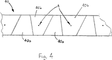
図4は、別々の部分40a,40bに裁断されたウェブ40を示している。その後、第2のウェブパネル40bをこれらの軸線Aの回りに回転させる。
【0023】
例えば、溶融接着剤のような接着剤を用い又は粘着性成分を用いた糊付け法により、或いは、超音波溶接法、ヒートシール法等の任意の従来方法を用いて、第1のウェブパネル40a及び第2のウェブパネル40bを受取りウェブ1に付着させ、好ましくはくっつける。
【図面の簡単な説明】
【図1】 本発明の方法の実施に用いられる装置の斜視図。
【図2】 図1の装置の側面図。
【図3a】 吸収用品の製造のための生産ラインの概略側面図。
【図3b】 本発明の装置を有する図3aに示すような生産ライン組立体の一部の概略側面図。
【図4】 本発明の方法の一実施形態による裁断後におけるウェブパネルの平面図。[0001]
The present invention relates to a method of manufacturing a deformed disposable absorbent article and an apparatus used to carry out this method. In a preferred embodiment, the present invention relates to a method and apparatus for forming a profile side panel, in particular an elastic side panel, without wasting its material. In particular, the method of the present invention can produce diapers or training pants with side “notches” to provide a good fit around the wearer's leg, but this method is It can also be applied to household hygiene products, adult incontinence products and other disposable absorbent products.
[0002]
Disposable absorbent articles are becoming very popular in the market today. Many of these articles have side panels that perform various functions, including various features, such as improved containment properties and a better and more comfortable fit.
[0003]
A matter to be preferentially considered in the manufacture of disposable absorbent articles is the cost of manufacturing articles including material costs. The present invention provides a method of manufacturing a side panel of an absorbent article with little or no wasted material. Thus, a side panel manufactured by the method of the present invention can be provided at a relatively lower cost than many of the side panels currently manufactured using material wasted methods. Methods for reducing or eliminating material waste are disclosed in the following technical literature.
[0004]
US Pat. No. 5,034,007, issued on July 23, 1991, cuts “combination ears” by placing convex and concave cuts in the longitudinal direction along the web at regular intervals. The method of forming is described. The two cut portions of the web are then separated and the cut portions are placed symmetrically across the width with the straight edges aligned on the inside and the convex / concave edges aligned on the outside. Another way of achieving the same result is disclosed in European Patent Application Publication No. 396,050, issued November 7, 1990. This discloses a technique in which all of the cut portions are individually reversed by rotating the cut portions 180 ° about an axis located in the plane of the web.
[0005]
PCT Application Publication No. WO 96/24319, issued August 15, 1996, before manufacturing side panels in an available state cut in a “combination” pattern and attaching the cut portion of the web to the diaper web. Discloses a method of rotating them all 180 ° about an axis located in the plane of the web (in particular this is shown in FIG. 7).
[0006]
It is an object of the present invention to provide another method for achieving the advantage of eliminating the “combination ear” waste and an apparatus used to implement this method.
[0007]
The present invention provides a method and apparatus for manufacturing a disposable absorbent article in which a plurality of first web panels and second web panels are cut from the same continuous web, and separate web panels are received and attached to the web. The manufacturing method includes a step of cutting a continuous web to form at least a first web panel and a second web panel, a step of rotating the second web panel, a first web panel, and a second web panel. And receiving the material on the receiving web.
[0008]
[Summary of the Invention]
The object of the invention is achieved by rotating the second web panel about an axis perpendicular to the plane of the second web panel.
[0009]
[Detailed Description of Embodiment]
FIG. 1 is a perspective view of the apparatus of the present invention. This device has two rotating
[0010]
The
[0011]
In the embodiment shown in FIG. 1, every other vacuum shell 80 b is attached to a rotatable shaft 81 and is rotatable 180 ° about an axis A that extends radially relative to the
[0012]
In addition, during the first part of the cycle, the shell lifting cam (not shown in FIGS. 1 and 2) acts to “lift” the vacuum shell 80b radially outward from the
[0013]
In the embodiment of the present invention shown in FIGS. 1 and 2, the
[0014]
FIG. 3 a is a side view of a continuous method of manufacturing
[0015]
FIG. 3 b shows an
[0016]
The receiving web 1 is transported along the upstream track 3 in the longitudinal direction F at a constant transport speed V 0 . The upstream track 3 extends to the right side of the first guide roller 9 in FIG. 3b and is formed by the length of the receiving web 1 that moves towards the
[0017]
The guide rollers 9 and 11 are rotatably connected to the
[0018]
The intermediate track 7 (7a, 7b, 7c) of the receiving web 1 is disposed between the upstream guide roller 9 and the downstream guide roller 11, and this intermediate track is the upstream guide roller 9 and the upstream transport roller 13. The first portion 7a has a variable length and is located between the downstream conveying
[0019]
Since the intermediate tracks 7a, 7b, and 7c are arranged symmetrically, when the sled member 41 is moved away from the
[0020]
When the second portion 7b receiving web portions located along the intermediate trajectory 7 is stationary relative to the frame 35 (or, at least, if slower than the web speed V 0), the web 1 and the
[0021]
The guide rollers 9, 11 and the
[0022]
FIG. 4 shows the
[0023]
For example, the first web panel 40a and the first web panel 40a can be obtained by using an adhesive such as a melt adhesive or a gluing method using an adhesive component, or using any conventional method such as an ultrasonic welding method or a heat sealing method. A
[Brief description of the drawings]
FIG. 1 is a perspective view of an apparatus used to carry out the method of the present invention.
FIG. 2 is a side view of the apparatus of FIG.
Fig. 3a is a schematic side view of a production line for the manufacture of absorbent articles.
3b is a schematic side view of a portion of a production line assembly as shown in FIG. 3a having the apparatus of the present invention.
FIG. 4 is a plan view of a web panel after cutting according to an embodiment of the method of the present invention.
Claims (3)
連続ウェブを切断して少なくとも第1のウェブパネル(40a)及び第2のウェブパネル(40b)を形成する工程と、
第2のウェブパネル(40b)を該第2のウェブパネル(40b)の平面に垂直な軸線(A)の回りに180°回転させる工程と、
前記第1のウェブパネル(40a)及び前記第2のウェブパネル(40b)を受取りウェブ(1 )に付着させる工程とを有することを特徴とする方法。A method of manufacturing a disposable absorbent article comprising the steps of attaching separate web panels (40a, 40b) to a receiving web (1), the method comprising:
Cutting the continuous web to form at least a first web panel (40a) and a second web panel (40b);
Rotating the second web panel (40b) by 180 ° about an axis (A) perpendicular to the plane of the second web panel (40b) ;
Wherein that chromatic and a step of attaching a web (1) receiving said first web panel (40a) and said second web panel (40b).
隣り合う第1のウェブパネル(40a)及び第2のウェブパネル(40b)を同一の連続ウェブ(40)から切断して少なくとも第1のウェブパネル(40a)及び第2のウェブパネル(40b)を形成する手段と、
前記第2のウェブパネル(40b)を回転させる手段と、
前記第1のウェブパネル(40a)及び前記第2のウェブパネル(40b)を受取りウェブ(1 )に付着させる手段と、を有し、
前記第2のウェブパネル(40b)は該第2のウェブパネル(40b)の平面に垂直な軸線(A)の回りに回転させられ、前記装置は別々の第1ウェブパネル(40a)及び第2ウェブパネル(40b)を受取りウェブ(1 )に付着させる2つの回転ドラム(60,70 )及び前記回転ドラム(60,70 )の各々の周囲にぐるりと配置された真空シェル(80a,80b)を有し、前記真空シェル(80a,80b)の少なくとも一つは前記第2ウェブパネル(40b)の平面に垂直な軸線(A)に関して回転可能であり、前記装置はさらに前記真空シェル(80a,80b)を前記ドラム(60,70 )の半径方向外方に持ち上げて移着工程で前記ウェブパネル(40a,40b)を前記受取りウェブ(1 )に付着させるシェル持上げカムを有していることを特徴とする装置(38)。 An apparatus (38) for carrying out the method according to claim 1, comprising means for attaching separate web panels (40a, 40b) to the receiving web (1) .
The adjacent first web panel (40a) and second web panel (40b) are cut from the same continuous web (40) so that at least the first web panel (40a) and the second web panel (40b) are obtained. Means to form;
It means for rotating said second web panel (40b),
Anda means for attaching the web (1) receiving said first web panel (40a) and said second web panel (40b),
Said second web panel (40b) is rotated around said second web panel axis perpendicular to the plane of (40b) (A), said device separate first web panel (40a) and a second Two rotating drums (60, 70) for attaching the web panel (40b) to the receiving web (1) and a vacuum shell (80a, 80b) disposed around each of the rotating drums (60, 70). And at least one of the vacuum shells (80a, 80b) is rotatable with respect to an axis (A) perpendicular to the plane of the second web panel (40b), and the apparatus further includes the vacuum shells (80a, 80b). ) Is lifted radially outward of the drum (60, 70) and has a shell lifting cam for adhering the web panel (40a, 40b) to the receiving web (1) in a transfer process. The device (38).
Applications Claiming Priority (3)
| Application Number | Priority Date | Filing Date | Title |
|---|---|---|---|
| EP99112228A EP1062928A1 (en) | 1999-06-25 | 1999-06-25 | Process for manufacturing disposable absorbent articles, and an apparatus for performing the process |
| EP99112228.4 | 1999-06-25 | ||
| PCT/US2000/017489 WO2001000122A1 (en) | 1999-06-25 | 2000-06-23 | Process for manufacturing disposable absorbent articles, and an apparatus for performing the process |
Publications (2)
| Publication Number | Publication Date |
|---|---|
| JP2003503108A JP2003503108A (en) | 2003-01-28 |
| JP4583683B2 true JP4583683B2 (en) | 2010-11-17 |
Family
ID=8238421
Family Applications (1)
| Application Number | Title | Priority Date | Filing Date |
|---|---|---|---|
| JP2001505839A Expired - Fee Related JP4583683B2 (en) | 1999-06-25 | 2000-06-23 | Method and apparatus for manufacturing disposable absorbent article |
Country Status (8)
| Country | Link |
|---|---|
| EP (2) | EP1062928A1 (en) |
| JP (1) | JP4583683B2 (en) |
| AT (1) | ATE291403T1 (en) |
| AU (1) | AU5890200A (en) |
| CA (1) | CA2375955A1 (en) |
| DE (1) | DE60018929T2 (en) |
| MX (1) | MXPA01013373A (en) |
| WO (1) | WO2001000122A1 (en) |
Families Citing this family (13)
| Publication number | Priority date | Publication date | Assignee | Title |
|---|---|---|---|---|
| DE19937729A1 (en) * | 1999-08-10 | 2001-02-15 | Lurgi Zimmer Ag | High tenacity polyester threads and process for their manufacture |
| US6702917B1 (en) | 2002-08-30 | 2004-03-09 | Kimberly-Clark Worldwide, Inc. | Cross-machine-direction nested absorbent pads with minimal waste geometries |
| US7070672B2 (en) | 2004-02-24 | 2006-07-04 | Kimberly-Clark Worldwide, Inc. | Process for making a feminine sanitary napkin or other absorbent article having place and cut wings |
| US7163529B2 (en) | 2004-12-15 | 2007-01-16 | Kimberly-Clark Worldwide, Inc. | Absorbent article having disposal wings with odor absorbency |
| JP4522342B2 (en) * | 2005-08-11 | 2010-08-11 | 花王株式会社 | Method and apparatus for manufacturing absorbent article |
| US10456302B2 (en) | 2006-05-18 | 2019-10-29 | Curt G. Joa, Inc. | Methods and apparatus for application of nested zero waste ear to traveling web |
| US9433538B2 (en) | 2006-05-18 | 2016-09-06 | Curt G. Joa, Inc. | Methods and apparatus for application of nested zero waste ear to traveling web and formation of articles using a dual cut slip unit |
| US8016972B2 (en) | 2007-05-09 | 2011-09-13 | Curt G. Joa, Inc. | Methods and apparatus for application of nested zero waste ear to traveling web |
| US9622918B2 (en) | 2006-05-18 | 2017-04-18 | Curt G. Joe, Inc. | Methods and apparatus for application of nested zero waste ear to traveling web |
| ITBO20120655A1 (en) * | 2012-12-03 | 2014-06-04 | Gdm Spa | MACHINE FOR THE CONSTRUCTION OF HYGIENIC ABSORBENT ITEMS. |
| CN103479480B (en) * | 2013-08-29 | 2015-05-20 | 安庆市恒昌机械制造有限责任公司 | On-line waistline cutting and rotating pitch-variable assembly for disposable sanitary product |
| US9289329B1 (en) | 2013-12-05 | 2016-03-22 | Curt G. Joa, Inc. | Method for producing pant type diapers |
| CN108481433B (en) * | 2018-04-20 | 2024-04-12 | 安庆市恒昌机械制造有限责任公司 | Sheet material transfer component and process |
Family Cites Families (12)
| Publication number | Priority date | Publication date | Assignee | Title |
|---|---|---|---|---|
| JPH0780610B2 (en) * | 1987-08-04 | 1995-08-30 | 株式会社瑞光 | Method of manufacturing disposable diapers |
| MY103655A (en) * | 1987-12-16 | 1993-08-28 | Kimberly Clark Co | Method and appratus for making a disposable incontinence garment or training pant |
| JPH0751143B2 (en) * | 1988-04-19 | 1995-06-05 | 株式会社瑞光 | How to make and attach elastic tape |
| JP2622414B2 (en) * | 1989-04-29 | 1997-06-18 | ユニ・チャーム株式会社 | Method of manufacturing component for wearing article |
| US5034007A (en) * | 1990-02-23 | 1991-07-23 | Uni-Charm Corporation | Manufacturing method for disposable clothing items |
| JPH04261655A (en) * | 1990-12-31 | 1992-09-17 | Zuikou:Kk | Manufacture of paper diaper |
| US5396978A (en) * | 1993-08-09 | 1995-03-14 | The Procter & Gamble Company | Apparatus for attaching elastic at an angle |
| ATE162495T1 (en) * | 1993-11-04 | 1998-02-15 | Procter & Gamble | METHOD AND DEVICE FOR PRODUCING AN ABSORBENT ARTICLE |
| JPH08661A (en) * | 1994-06-24 | 1996-01-09 | Honshu Paper Co Ltd | Surface material for diaper having pocket structure and its manufacture and diaper |
| US5580411A (en) * | 1995-02-10 | 1996-12-03 | The Procter & Gamble Company | Zero scrap method for manufacturing side panels for absorbent articles |
| JP3131130B2 (en) * | 1995-09-29 | 2001-01-31 | ユニ・チャーム株式会社 | Manufacturing method of wearing article constituent member |
| US5660665A (en) * | 1995-12-15 | 1997-08-26 | Kimberly-Clark Corporation | Rotating transfer roll with rotating extensible platen |
-
1999
- 1999-06-25 EP EP99112228A patent/EP1062928A1/en not_active Withdrawn
-
2000
- 2000-06-23 EP EP00944871A patent/EP1189564B1/en not_active Expired - Lifetime
- 2000-06-23 CA CA002375955A patent/CA2375955A1/en not_active Abandoned
- 2000-06-23 AU AU58902/00A patent/AU5890200A/en not_active Abandoned
- 2000-06-23 DE DE60018929T patent/DE60018929T2/en not_active Expired - Lifetime
- 2000-06-23 AT AT00944871T patent/ATE291403T1/en not_active IP Right Cessation
- 2000-06-23 MX MXPA01013373A patent/MXPA01013373A/en unknown
- 2000-06-23 JP JP2001505839A patent/JP4583683B2/en not_active Expired - Fee Related
- 2000-06-23 WO PCT/US2000/017489 patent/WO2001000122A1/en active IP Right Grant
Also Published As
| Publication number | Publication date |
|---|---|
| EP1189564A1 (en) | 2002-03-27 |
| ATE291403T1 (en) | 2005-04-15 |
| CA2375955A1 (en) | 2001-01-04 |
| AU5890200A (en) | 2001-01-31 |
| EP1062928A1 (en) | 2000-12-27 |
| EP1189564B1 (en) | 2005-03-23 |
| DE60018929D1 (en) | 2005-04-28 |
| DE60018929T2 (en) | 2006-03-30 |
| JP2003503108A (en) | 2003-01-28 |
| WO2001000122A1 (en) | 2001-01-04 |
| MXPA01013373A (en) | 2002-07-02 |
Similar Documents
| Publication | Publication Date | Title |
|---|---|---|
| US6730189B1 (en) | Process for manufacturing disposable absorbent articles, and an apparatus for performing the process | |
| JP2615189B2 (en) | Device for attaching stretched elastic piece to moving web | |
| JP3466230B2 (en) | Method and apparatus for attaching an elastic member | |
| CA2745924C (en) | An elastic composite having cross-directional elasticity and a system and method for making the elastic composite | |
| JP4583683B2 (en) | Method and apparatus for manufacturing disposable absorbent article | |
| US4293367A (en) | Apparatus for effecting securement of a transversely moved elastic ribbon to a moving web | |
| KR101297929B1 (en) | Apparatus and method for making pre-fastened absorbent undergarments | |
| CN103126809B (en) | Produce the system and method for elastic composite | |
| JP5624868B2 (en) | Method for manufacturing absorbent article | |
| JPH0213454A (en) | Apparatus and method for producing disposable diaper | |
| JP2004148040A (en) | Apparatus for producing wear article | |
| MXPA02011203A (en) | Method and apparatus for making garments with refastenable seams. | |
| JP2002345889A (en) | Rotary apparatus, method for conveying wearing article, method for folding web, apparatus for folding web and disporsable wearing article | |
| KR20020034097A (en) | Assembly and method for rotating and placing strip of material on a substrate | |
| JP4583684B2 (en) | Method and apparatus for producing disposable absorbent core | |
| EP1552798B1 (en) | Disposable diaper inside leg bending device and inside leg bending method | |
| KR101518098B1 (en) | Method of manufacturing absorptive article | |
| KR100284476B1 (en) | Method, apparatus, and preform for making an undergarment having side seams | |
| US6736923B1 (en) | Process for manufacturing disposable absorbent cores, and an apparatus for performing the process | |
| WO2011004605A1 (en) | Method and apparatus for making disposable diaper | |
| EP0443244A1 (en) | Method and apparatus for applying an elastic waistband to a disposable diaper | |
| TWI556800B (en) | Apparatus for building | |
| JPH09110019A (en) | Folding method of article and device thereof | |
| JP2001346825A (en) | Method and apparatus for manufacturing diaper and diaper | |
| JPH06209968A (en) | Installation of waist band of paper diaper |
Legal Events
| Date | Code | Title | Description |
|---|---|---|---|
| A621 | Written request for application examination |
Free format text: JAPANESE INTERMEDIATE CODE: A621 Effective date: 20070523 |
|
| A977 | Report on retrieval |
Free format text: JAPANESE INTERMEDIATE CODE: A971007 Effective date: 20090929 |
|
| A131 | Notification of reasons for refusal |
Free format text: JAPANESE INTERMEDIATE CODE: A131 Effective date: 20091013 |
|
| A601 | Written request for extension of time |
Free format text: JAPANESE INTERMEDIATE CODE: A601 Effective date: 20100113 |
|
| A602 | Written permission of extension of time |
Free format text: JAPANESE INTERMEDIATE CODE: A602 Effective date: 20100120 |
|
| A521 | Request for written amendment filed |
Free format text: JAPANESE INTERMEDIATE CODE: A523 Effective date: 20100215 |
|
| TRDD | Decision of grant or rejection written | ||
| A01 | Written decision to grant a patent or to grant a registration (utility model) |
Free format text: JAPANESE INTERMEDIATE CODE: A01 Effective date: 20100806 |
|
| A01 | Written decision to grant a patent or to grant a registration (utility model) |
Free format text: JAPANESE INTERMEDIATE CODE: A01 |
|
| A61 | First payment of annual fees (during grant procedure) |
Free format text: JAPANESE INTERMEDIATE CODE: A61 Effective date: 20100901 |
|
| R150 | Certificate of patent or registration of utility model |
Free format text: JAPANESE INTERMEDIATE CODE: R150 |
|
| FPAY | Renewal fee payment (event date is renewal date of database) |
Free format text: PAYMENT UNTIL: 20130910 Year of fee payment: 3 |
|
| R250 | Receipt of annual fees |
Free format text: JAPANESE INTERMEDIATE CODE: R250 |
|
| R250 | Receipt of annual fees |
Free format text: JAPANESE INTERMEDIATE CODE: R250 |
|
| R250 | Receipt of annual fees |
Free format text: JAPANESE INTERMEDIATE CODE: R250 |
|
| LAPS | Cancellation because of no payment of annual fees |