JP4583605B2 - Optical cable for telecommunications - Google Patents
Optical cable for telecommunications Download PDFInfo
- Publication number
- JP4583605B2 JP4583605B2 JP2000609826A JP2000609826A JP4583605B2 JP 4583605 B2 JP4583605 B2 JP 4583605B2 JP 2000609826 A JP2000609826 A JP 2000609826A JP 2000609826 A JP2000609826 A JP 2000609826A JP 4583605 B2 JP4583605 B2 JP 4583605B2
- Authority
- JP
- Japan
- Prior art keywords
- optical fiber
- cable
- optical
- range
- twist
- Prior art date
- Legal status (The legal status is an assumption and is not a legal conclusion. Google has not performed a legal analysis and makes no representation as to the accuracy of the status listed.)
- Expired - Fee Related
Links
- 230000003287 optical effect Effects 0.000 title claims description 116
- 239000013307 optical fiber Substances 0.000 claims description 248
- 238000001125 extrusion Methods 0.000 claims description 62
- 238000000034 method Methods 0.000 claims description 60
- 239000002861 polymer material Substances 0.000 claims description 40
- 238000004519 manufacturing process Methods 0.000 claims description 39
- 238000004804 winding Methods 0.000 claims description 36
- 239000000463 material Substances 0.000 claims description 30
- 239000004952 Polyamide Substances 0.000 claims description 4
- 239000000155 melt Substances 0.000 claims description 4
- 229920002647 polyamide Polymers 0.000 claims description 4
- 102100032352 Leukemia inhibitory factor Human genes 0.000 claims description 3
- 108090000581 Leukemia inhibitory factor Proteins 0.000 claims description 3
- 229920000098 polyolefin Polymers 0.000 claims description 3
- 238000011144 upstream manufacturing Methods 0.000 claims description 3
- 229920001281 polyalkylene Polymers 0.000 claims 1
- 230000011514 reflex Effects 0.000 claims 1
- 235000015067 sauces Nutrition 0.000 claims 1
- 239000010410 layer Substances 0.000 description 77
- 230000035882 stress Effects 0.000 description 33
- 239000000835 fiber Substances 0.000 description 28
- 230000003014 reinforcing effect Effects 0.000 description 22
- 230000000694 effects Effects 0.000 description 19
- 230000008569 process Effects 0.000 description 19
- 238000012545 processing Methods 0.000 description 18
- 238000001816 cooling Methods 0.000 description 14
- 239000006096 absorbing agent Substances 0.000 description 12
- 238000005259 measurement Methods 0.000 description 12
- 229920000642 polymer Polymers 0.000 description 12
- 230000035939 shock Effects 0.000 description 12
- 238000010438 heat treatment Methods 0.000 description 10
- 238000003860 storage Methods 0.000 description 10
- 230000033001 locomotion Effects 0.000 description 9
- 238000003754 machining Methods 0.000 description 9
- -1 polyethylene Polymers 0.000 description 7
- 229920001971 elastomer Polymers 0.000 description 6
- 239000000806 elastomer Substances 0.000 description 6
- 230000001681 protective effect Effects 0.000 description 6
- 230000005540 biological transmission Effects 0.000 description 5
- 238000000151 deposition Methods 0.000 description 5
- 229920002725 thermoplastic elastomer Polymers 0.000 description 5
- 229910000831 Steel Inorganic materials 0.000 description 4
- 230000009471 action Effects 0.000 description 4
- 238000005452 bending Methods 0.000 description 4
- 230000008859 change Effects 0.000 description 4
- 238000013461 design Methods 0.000 description 4
- 230000000737 periodic effect Effects 0.000 description 4
- 230000003595 spectral effect Effects 0.000 description 4
- 239000010959 steel Substances 0.000 description 4
- XLYOFNOQVPJJNP-UHFFFAOYSA-N water Substances O XLYOFNOQVPJJNP-UHFFFAOYSA-N 0.000 description 4
- 239000004698 Polyethylene Substances 0.000 description 3
- 230000007547 defect Effects 0.000 description 3
- 239000006185 dispersion Substances 0.000 description 3
- 229920000573 polyethylene Polymers 0.000 description 3
- 238000012360 testing method Methods 0.000 description 3
- 229920001283 Polyalkylene terephthalate Polymers 0.000 description 2
- 239000004743 Polypropylene Substances 0.000 description 2
- NIXOWILDQLNWCW-UHFFFAOYSA-N acrylic acid group Chemical group C(C=C)(=O)O NIXOWILDQLNWCW-UHFFFAOYSA-N 0.000 description 2
- 230000002411 adverse Effects 0.000 description 2
- 230000015556 catabolic process Effects 0.000 description 2
- 238000004891 communication Methods 0.000 description 2
- 230000006835 compression Effects 0.000 description 2
- 238000007906 compression Methods 0.000 description 2
- 238000006731 degradation reaction Methods 0.000 description 2
- 238000010586 diagram Methods 0.000 description 2
- 238000009826 distribution Methods 0.000 description 2
- 238000009434 installation Methods 0.000 description 2
- 238000002844 melting Methods 0.000 description 2
- 230000008018 melting Effects 0.000 description 2
- 239000002184 metal Substances 0.000 description 2
- 229910052751 metal Inorganic materials 0.000 description 2
- 238000012986 modification Methods 0.000 description 2
- 230000004048 modification Effects 0.000 description 2
- 229920001155 polypropylene Polymers 0.000 description 2
- 230000000750 progressive effect Effects 0.000 description 2
- 230000002829 reductive effect Effects 0.000 description 2
- 230000002787 reinforcement Effects 0.000 description 2
- 239000012815 thermoplastic material Substances 0.000 description 2
- 229920000178 Acrylic resin Polymers 0.000 description 1
- 239000004925 Acrylic resin Substances 0.000 description 1
- 102100022299 All trans-polyprenyl-diphosphate synthase PDSS1 Human genes 0.000 description 1
- 241001589086 Bellapiscis medius Species 0.000 description 1
- 229920000049 Carbon (fiber) Polymers 0.000 description 1
- RYGMFSIKBFXOCR-UHFFFAOYSA-N Copper Chemical compound [Cu] RYGMFSIKBFXOCR-UHFFFAOYSA-N 0.000 description 1
- 101150115672 DPS1 gene Proteins 0.000 description 1
- 229920000271 Kevlar® Polymers 0.000 description 1
- 239000004677 Nylon Substances 0.000 description 1
- 101150063720 PDSS1 gene Proteins 0.000 description 1
- 230000003321 amplification Effects 0.000 description 1
- 239000004760 aramid Substances 0.000 description 1
- 229920003235 aromatic polyamide Polymers 0.000 description 1
- 230000002238 attenuated effect Effects 0.000 description 1
- 239000004917 carbon fiber Substances 0.000 description 1
- 238000005253 cladding Methods 0.000 description 1
- 239000011247 coating layer Substances 0.000 description 1
- 239000012141 concentrate Substances 0.000 description 1
- 238000010276 construction Methods 0.000 description 1
- 229910052802 copper Inorganic materials 0.000 description 1
- 239000010949 copper Substances 0.000 description 1
- 230000007423 decrease Effects 0.000 description 1
- 230000008021 deposition Effects 0.000 description 1
- 101150053419 dps2 gene Proteins 0.000 description 1
- 230000005611 electricity Effects 0.000 description 1
- 238000005516 engineering process Methods 0.000 description 1
- 230000007613 environmental effect Effects 0.000 description 1
- 230000006355 external stress Effects 0.000 description 1
- 239000011521 glass Substances 0.000 description 1
- 239000003365 glass fiber Substances 0.000 description 1
- 238000007602 hot air drying Methods 0.000 description 1
- 230000002706 hydrostatic effect Effects 0.000 description 1
- 238000003780 insertion Methods 0.000 description 1
- 230000037431 insertion Effects 0.000 description 1
- 238000009413 insulation Methods 0.000 description 1
- 230000001788 irregular Effects 0.000 description 1
- 239000004761 kevlar Substances 0.000 description 1
- 230000000670 limiting effect Effects 0.000 description 1
- 239000007769 metal material Substances 0.000 description 1
- VNWKTOKETHGBQD-UHFFFAOYSA-N methane Chemical compound C VNWKTOKETHGBQD-UHFFFAOYSA-N 0.000 description 1
- 238000000465 moulding Methods 0.000 description 1
- QVRVXSZKCXFBTE-UHFFFAOYSA-N n-[4-(6,7-dimethoxy-3,4-dihydro-1h-isoquinolin-2-yl)butyl]-2-(2-fluoroethoxy)-5-methylbenzamide Chemical compound C1C=2C=C(OC)C(OC)=CC=2CCN1CCCCNC(=O)C1=CC(C)=CC=C1OCCF QVRVXSZKCXFBTE-UHFFFAOYSA-N 0.000 description 1
- 238000003199 nucleic acid amplification method Methods 0.000 description 1
- 229920001778 nylon Polymers 0.000 description 1
- 230000035515 penetration Effects 0.000 description 1
- 230000000704 physical effect Effects 0.000 description 1
- 239000004033 plastic Substances 0.000 description 1
- 229920003023 plastic Polymers 0.000 description 1
- 230000010287 polarization Effects 0.000 description 1
- 229920001707 polybutylene terephthalate Polymers 0.000 description 1
- 229920000728 polyester Polymers 0.000 description 1
- 238000003825 pressing Methods 0.000 description 1
- 230000001902 propagating effect Effects 0.000 description 1
- 238000011084 recovery Methods 0.000 description 1
- 230000009467 reduction Effects 0.000 description 1
- 229920005989 resin Polymers 0.000 description 1
- 239000011347 resin Substances 0.000 description 1
- 230000000452 restraining effect Effects 0.000 description 1
- 230000002441 reversible effect Effects 0.000 description 1
- 238000000926 separation method Methods 0.000 description 1
- 239000002356 single layer Substances 0.000 description 1
- 238000009987 spinning Methods 0.000 description 1
- 229920001169 thermoplastic Polymers 0.000 description 1
- 229920005992 thermoplastic resin Polymers 0.000 description 1
- 239000003643 water by type Substances 0.000 description 1
Images


Classifications
-
- G—PHYSICS
- G02—OPTICS
- G02B—OPTICAL ELEMENTS, SYSTEMS OR APPARATUS
- G02B6/00—Light guides; Structural details of arrangements comprising light guides and other optical elements, e.g. couplings
- G02B6/44—Mechanical structures for providing tensile strength and external protection for fibres, e.g. optical transmission cables
- G02B6/4401—Optical cables
- G02B6/441—Optical cables built up from sub-bundles
- G02B6/4413—Helical structure
-
- G—PHYSICS
- G02—OPTICS
- G02B—OPTICAL ELEMENTS, SYSTEMS OR APPARATUS
- G02B6/00—Light guides; Structural details of arrangements comprising light guides and other optical elements, e.g. couplings
- G02B6/44—Mechanical structures for providing tensile strength and external protection for fibres, e.g. optical transmission cables
- G02B6/4401—Optical cables
- G02B6/4429—Means specially adapted for strengthening or protecting the cables
- G02B6/4434—Central member to take up tensile loads
-
- G—PHYSICS
- G02—OPTICS
- G02B—OPTICAL ELEMENTS, SYSTEMS OR APPARATUS
- G02B6/00—Light guides; Structural details of arrangements comprising light guides and other optical elements, e.g. couplings
- G02B6/44—Mechanical structures for providing tensile strength and external protection for fibres, e.g. optical transmission cables
- G02B6/4479—Manufacturing methods of optical cables
- G02B6/4484—Manufacturing methods of optical cables with desired surplus length between fibres and protection features
Landscapes
- Physics & Mathematics (AREA)
- General Physics & Mathematics (AREA)
- Optics & Photonics (AREA)
- Extrusion Moulding Of Plastics Or The Like (AREA)
- Communication Cables (AREA)
- Addition Polymer Or Copolymer, Post-Treatments, Or Chemical Modifications (AREA)
- Optical Fibers, Optical Fiber Cores, And Optical Fiber Bundles (AREA)
Description
【0001】
本発明は、電気通信用の光ケーブル、特に、長距離に亙って且つ高伝送速度にて作動する多重波長電気通信装置用の海底光ケーブルに関する。
【0002】
海底の適用に適した光ケーブルは、通常、光信号を伝送する複数の光ファイバを内蔵する光コアと、1つ以上の外部補強及び保護ライニングとを備えている。該光コアは、中央支持要素を備え、該中央支持要素の周りに光ファイバが一定の位置にて組み込まれた1つ以上のポリマー材料層とを備える型式のものであることが好ましい。
【0003】
海底の適用例の場合、ケーブルは過酷な環境条件にて作動しなければならず、特に、該ケーブルは、極めて高圧力及び腐蝕媒体の作用に耐えなければならない。更に、ケーブルは、海中での付設中及び回収を伴う作動中に、ケーブルに加わる大きい機械的応力、特に、牽引応力及び曲げ応力に耐えるものでなければならない。これら応力の結果としてケーブル内で発生された力は光ファイバに伝達され且つ伝送された信号の減衰の点にて悪影響を与える可能性がある。
【0004】
従来、海底の適用例に適した光ケーブルに対する色々な形態が提案されている。
ソシエタ・カビ・ピレリー(Societa Cavi Pirelli)S.p.A.の名による米国特許第4,744,935号には、半径方向最内側位置にて、ポリマー材料本体内に組み込まれた牽引力抵抗性コア等を備えることが好ましい構造体であって、該ポリマー材料本体内にルーズな保護状態で配置した光ファイバが埋め込まれた構造のケーブルが提案されている。これらの光ファイバは、開螺旋に配置される、すなわち、第一の巻き方向を有する部分が反対の巻き方向を有する部分と交番的となる軌線に沿って配置されている。
【0005】
アルケテル・アルスソム・コンパニエ・ジェネラル・デ´エレクトリサイト(ALCATEL ALSTHOM COMPAGNIE GENERALE D´ELECTRICITE)」の名による欧州特許出願第851258 A1号は、ファイバが中央部材の周りで螺旋状に巻かれ、また、該ファイバが中央部材と共に水の浸透及び流れを防止する単一の構造体を画定する被覆層内に組み込まれた光ファイバケーブルに関するものである。この光ファイバは、S又はSZ螺旋(すなわち、閉又は開螺旋にて巻かれている)。ファイバは、中央部材の周りに配置されているため、被覆層が該中央部材の上にて押出し成形されている。このことは、中央部材の周りにファイバの案内穴を有し且つ一方向に又は両方向に交互に回転し得るようにされた押出し成形ダイによって行われる。
【0006】
エイティー・アンド・ティー・ベル・エルエイビー(AT&T BELL LAB)の名による米国特許第4,541,970号には、第一の熱可塑性エラストマーの層をそれ以前に加熱した補強要素の周りで押出し成形することと、光ファイバを螺旋に配置することと、第一のエラストマー層の上で「遊星動作」技術を使用することと、第二のエラストマー材料層を第一のエラストマー層上に押出し成形することとを備える、海底通信用ケーブルのコアの製造方法が提案されている。「遊星動作」技術に従って光ファイバを巻くことは、光ファイバを保持するリールと、光ファイバをケージから押出し成形機に向ける適当なガイドとが関係した回転ケージから成る装置によって行われる。特に、光ファイバを巻き戻すリールは、ケージが回転するとき、その軸線が一定の方向に平行のままであるような仕方にて支持されている。この技術により、光ファイバに付与される捩れ力は特に小さくなる。
【0007】
STC PLCの名による米国特許第4,902,097号には、熱可塑性エラストマー層を中央要素の周りで押出し成形するステップと、表面をその融点以上まで加熱するステップと、複数の光ファイバをこの表面に組み込むステップと、第二の熱可塑性エラストマー層をファイバを覆い得るように押出し成形するステップとを備える、光ファイバを製造する更なる技術が提案されている。この場合、光ファイバは第一の層内に部分的に組み込まれ、また、第二のエラストマー層内に部分的に組み込まれる。光ファイバは、零に等しい巻き角度に配置される、すなわち、これら光ファイバは互いに対し且つケーブルの中心軸線に対して平行に配置されている。
【0008】
STC PLCの名による米国特許第4,832,441号には、海底の適用例に適した光ケーブルが提案されており、該ケーブルは、中央フィラメントと、アクリレイトでライニングされ且つ単一押出し成形法、すなわち、いわゆるワンショット工程技術を使用して得られた低融点のプラスチック材料層内に組み込まれた複数の光ファイバとを備えている。この場合にも、光ファイバは、零に等しい巻き角度にて配置されている。
【0009】
エイテー・アンド・テー・コーポレーション(AT&T Corp.)の名による米国特許第5,440,659号には、ケーブルの製造工程中、光ファイバの各々に制御された捩れ力を付与することを含む、光ファイバケーブルの製造方法が提案されている。付与された捩れ力は、光ファイバの全長に沿って均一である。光ファイバが螺旋にて中央要素に押出し成形された第一の熱可塑性材料層に巻かれ、更なる熱可塑性材料層は光ファイバに押出し成形される。光ファイバを螺旋に沿って螺旋状に巻くためには、上述した米国特許第4,541,970号に使用したものと同様の回転ケージが使用されるが、光ファイバを保持するリールは、ケージ自体に固定するか又は制御された仕方にて回転し、光コアの製造工程中、光ファイバに付与される捩れ力を制御する。
【0010】
エステーシー・サブマリン・システムズ・リミテッド(STC Submarine Systems Limited)の名による英国特許出願第2,303,938号は、光ファイバケーブル及びその関係する製造方法に関するものである。この提案された方法は、中央要素の周りに熱可塑性エラストマー層を押出し成形することと、エラストマー層を硬化させる(冷却により)ことと、硬化したエラストマーに沿って複数の光ファイバを配置することと、光ファイバの頂部に更なる熱可塑性エラストマー層を押出し成形することとを含む。光ファイバは、追加的な層を押出し成形する前に、それ自体の軸線の周りで撚り且つ/又は第一の層の周りで螺旋に沿って巻くことができる。この撚り及び/又は巻き工程は、連続的とし又は所定の角度にて交番的に行うことができる。
【0011】
硬化したエラストマーの層の上に光ファイバを付着する技術は、本明細書の便宜のため、「正接付着技術(tangential deposition technique)」として以下に説明する。
【0012】
当該出願人は、上述した既知の方法を使用して製造されたケーブルは信号の減衰及び/又は方向モード分散(「PMD」)の点にて問題点があることが分かった。
【0013】
光ケーブル内の信号の光パワーの減衰は、長距離光電気通信装置における特に重大な問題点である。かかる装置において、信号の正確な捕捉を確実にするためには、互いに所定の距離(例えば、数百キロメートルの距離)に配置された信号増幅器を使用することが必要となる。これらの信号増幅器は、典型的に、好ましくは伝送帯域内で実質的に平坦な増幅帯域を有する活性ファイバ型の光増幅器である。多重波長電気通信装置において、光ケーブル内の信号に対する減衰程度は波長に依存するから、電気通信装置の増幅器は全体として、非等化信号を受信する。この欠点を解決するため、例えば、色々な通信チャネル(チャネルの各々が該チャネルと関係したそれぞれの波長を有する)内の光パワーを等化し得るように増幅器自体又は線に沿って配置された信号イコイライザーを使用することが既知である。
【0014】
既知であるように、正確な等化を実現するためには、光ファイバのスペクトル減衰曲線が伝送帯域内で実質的に一定で且つ予見可能な勾配を有することが必要とされる。全体として、光電気通信用のケーブルにおいて、伝送された信号の減衰程度は、例えば、製造工程中、ケーブルの巻き戻し工程中又はケーブル自体に行われた工程中に発生される、ケーブル内に存在する力の状態に依存する。更に、ケーブル自体内に光ファイバのマイクロ曲がりが存在するとき、信号の減衰程度が増す。
【0015】
当該出願人は、正接付着技術(上述した英国特許出願第2,303,938号に記載)を使用して、2つの押し出し材料層と、第一の層の上に配置された複数の光ファイバとを備える型式のケーブルは、光ファイバのマイクロ曲がり効果の結果として減衰に関係する問題点を生じることが分かった。当該出願人は、実際に、第二の層を第一の層に押出し成形する間、光ファイバと第一の押出し成形層との間に空気のマイクロキャビティが形成されることが分かった。これらのマイクロキャビティの存在の結果、光ファイバは局部的に変位し、このため、ファイバ自体のマイクロ曲がり状態を発生させる可能性がある。上述したように、マイクロ曲がりの結果、伝送された信号が減衰し、この減衰程度は波長に依存するため、スペクトル減衰曲線は、ケーブルの製造前の光ファイバの減衰曲線と比べて僅かでない変化が生じる。このケーブルの製造に起因するスペクトルの減衰曲線の変化は、実際の装置の設計段階中に考慮することのできない装置の伝送性能に関して予見不能な要素を導入するため、欠点を招来することになる。このため、ケーブルの製造後の減衰曲線の顕著な変化の結果、信号の減衰の点に望ましくない装置の振舞いを生じ、また、装置自体内での信号の等化が非効率的となる可能性がある。
【0016】
当該出願人は、この光ケーブルはまた、PMDに関係する問題点を有することも分かった。光ファイバ内で伝送される信号のPMDは、信号自体の直交モードを伝播するときの群速度が相違することに起因する。デジタル信号の場合、この相違により伝送されたビット外の間隔となり、それに伴い信号が劣化する。
【0017】
ケーブルに製造した光ファイバ内のPMDは、ケーブルの製造過程の結果として光ファイバに影響を与える形態の変化に依存する。全体として、光ファイバが局部的に応力を受けるならば、この帯域内で直交伝播モード間の局部的な遅れが生じる。光ファイバに沿って導入される遅れの合計値がPMDを決定することになる。
【0018】
更に詳細には、当該出願人は、ケーブルを製造する色々な段階中、半径方向応力がケーブル内で付与され且つケーブル自体の全長に亙って伸び且つ光ファイバの断面を変形させる可能性があることが分かった。特に、光コアの製造過程中、光コア内部で張力を「蓄積」し、その結果、半径方向応力が光コア自体の断面に亙って斜めの方向に実質的に均一に連続的に分配される状態となる。この応力状態の結果、光ファイバは変形し、このため、PMDが増大する。その後の加工中、及びポリエチレンシースの通常の施工工程中に、光コアの加圧の間に生じる半径方向応力により同様の効果が生じる。
【0019】
当該出願人は、ケーブルの製造に起因するPMDの増加に寄与する更なるファクタは特に、外部の補強及び保護ライニングの楕円形の幾何学的製造上の欠点から成ることが分かった。
【0020】
この場合、応力は半径方向に作用するが、その応力は変形が集中するケーブルの横方向部分に主として作用するから、斜め方向に均一に分配されない。これらの応力は、ファイバが互いに対し平行に配置されるか又は中央要素の周りで巻かれるかどうかに依存して、連続的又は周期的な仕方にて光ファイバに作用する可能性がある。この後者の場合、応力の効果は、光ファイバ自体の周期的な巻き速度に依存する。
【0021】
当該出願人は、光ファイバが部分的に第一の層に組み込まれ且つ部分的に第二のポリマー層に組み込まれる型式のケーブルの場合(上述した米国特許第4,902,097号に記載されたもののような場合)、第二の層の押出し成形中、光ファイバに作用する応力が光ファイバに一定の横方向圧力を加え、その結果、PMDに関係した伝送特性が劣化することが分かった。
【0022】
全体として、更に、当該出願人は、2つの層材料に影響を与える異なる押出し及び冷却状態のため、また、表面の可能な欠点が存在し、又はその押出し成形後の最内側層の形態のため、2つの連続的な段階を含む押出し成形技術の結果、典型的に、光ファイバが存在する領域内で力が生じることが分かった。これらの力は、また、材料自体の冷却中又は光コアの外側のライニングの高温度付着に続く冷却中、押出し成形した材料の収縮現象によっても増大する可能性がある。
【0023】
単一のポリマー材料層を有する上述した引例による唯一のケーブルの型式は、ファイバが互いに平行に配置された上述した米国特許第4,832,441号に記載されたものである。ファイバを互いに平行に配置するこの形態(上述した米国特許第4,902,097号にも記載されている)は、この形態において、光ファイバが全体として一定の応力状態にあるから、PMDの点にて不利益である。実際上、製造工程中及びケーブルの付設中に存在する応力及び外的媒体に起因する応力は、常に各光ファイバの同一の母線に沿って作用する。このため、この光ファイバは複屈折型となり、このため、PMDの点にて性能が劣化する。
【0024】
当該出願人は、光ファイバが螺旋に沿って巻かれるが、捩れを生じない場合(例えば、上述した米国特許第4,541,970号に記載されたように)、すなわち、その母線の1つが常に同一の方向に方向決めされたとき、応力に起因する上述した問題点は、目立たないが依然として、PMDを増大させ勝ちとなる。この場合、実際上、応力は定期的に同一の母線に作用し、このため、光ファイバの断面に沿って複屈折を生じさせる(平行なファイバの場合と比べてより少ない程度ではあるが)、その結果、PMDが増大する。
【0025】
光ファイバの巻き状態が「閉」螺旋型である場合、すなわち、常に同一方向に向けられる場合(例えば、AT&Tの名による上記に引用した米国特許第5,440,659号に記載されたように)、また、光ファイバの非零捩れ状態と関係した場合、当該出願人は、PMDの点にて更なる不利益な点があることが分かった。この型式の巻き状態は、実際上、光弾性及び複屈折を発生させ、その結果、PMDを増大させ勝ちとなる弾性的な捩れを各光ファイバ内に生じさせる。この現象は、例えば、1981年10月1日のエレクトロニック・レターズ(ELECTRONIC LETTERS)、Vol.17、No.20、725−726ページのA.J.バロウ(Barlow)、D.N.ペイン(Pyne)、M.R.ハドレイ(Hadley)、R.J.マンスフィールド(Mandsfield)による「無視可能な固有の複屈折及び方向モード分散を伴う単モードファイバの製造(Production of single−mode fiberes with negligible intrinsic birefringence and polarisation mode dispersion)」という名称の論文に記載されている。この論文において、コラム1の終わりから2番目の文節には、スピニング後に撚った光ファイバ中に捩れ応力が存在し、その結果、光弾性効果に起因する大きい円形の複屈折が生じることが指摘されている。
【0026】
更に、光ファイバの捩れ角度が中央要素の周りのファイバ自体の巻き角度に等しいように設定されるならば(上述した米国特許第5,440,659号に提案されたように)、光ファイバの各々は、常に、同一の母線に沿って半径方向応力に曝され、その結果、PMDが無視し得ない程度に増大する。この状態が存在しない場合でさえ(すなわち、捩れ角度が巻き角度と相違する場合)、「均一な」巻き状態(すなわち、一定の巻き速度)である結果、光ファイバの同一の母線に沿って、周期的な性質の応力が生じることになる。最後に、撚りを伴う閉螺旋の形態にて上述のように巻く結果、光ファイバに沿って連続的な機械的応力が生じ、この応力の結果、ファイバ自体が構造的に弱体化する可能性がある。
【0027】
本発明によれば、不連続部分が存在せず、上記ケーブルにて測定したPMDが、ケーブル化される前の同一型式の光ファイバで測定したPMDの110%未満であるように選んだ捩れ程度を有するポリマー材料層内に、「開」螺旋の軌線に沿って巻かれる光コアが完全に組み込まれた、光ファイバケーブルが提案される。特に、ファイバの最大の局部的な捩れ程度は、0.05回/m(又は撚り数/m)乃至1.5回/m、好ましくは0.1回/m乃至1回/mの範囲にある。
【0028】
ポリマー材料層は、単一の押出し工程を使用して得られるため、不連続部分が存在しない。
以下に、「開」螺旋軌線又は「SZ」軌線は、軸線自体の周りの交番的な回転動作と中央軸線に対して平行な方向への並進動作とを組み合わせることに起因する円筒状面に沿った軌線を意味するものと理解する。基本的に、この型式の軌線は、「閉」螺旋軌線と相違し、それは、中央軸線の周りの巻き工程は、常に同一の方向に向けて行われるとは限らず、時計回り方向及び反時計回り方向に交番的に行われるからである。
【0029】
本発明に従って製造したケーブルの場合、押出し成形した2つのポリマー層の間にファイバが配置される光ファイバに関係する欠点が解消される。実際上、信号の減衰の点にて、単一のポリマー材料層が存在することは、正接付着技術を使用して製造された光コア中に存在する光ファイバのマイクロ曲がりという問題点を解消する。PMDの点にて、光ファイバの特別な配置の結果、平行に配置されたファイバ及び「閉」螺旋に沿って配置されたファイバから成る形態に関して上述した欠点が減少する。
【0030】
当該出願人は、単一のポリマー材料層内で交番的に撚ると共に、局部的な所定の捩れを伴って光ファイバを「開」螺旋に沿って配置することは特に、PMDに関して特に好ましい状態を表わすことが分かった。実際に、この形態の結果、光ファイバの表面に亙ってケーブルに作用する応力が極めて不規則的に配分され、このため、信号の直交モードの群速度の差が減少する。更に、交番的な撚りが存在するため、そのコアの幾何学的欠陥に依存して光ファイバの固有のPMDを減少させ、これと同時に、上述したようにPMDの増加につながる光弾性効果に悪影響を与えないようにすることが可能である。
【0031】
同様に、本発明の主題を形成する本発明によるケーブルの製造方法は、光コアを製造するのに1回の押出し成形工程で足りるから、特に簡単で且つ迅速であり、また、「遊星動作」技術のケージのような複雑な機械が不要であるから、特に低コストである。
【0032】
第一の面によれば、本発明は、少なくとも1つの光ファイバをストランド状要素と接触して押出し成形したポリマー材料内に組み込むステップを備える、光ケーブルの製造方法であって、ポリマー材料中に組み込む上記ステップが、
上記光ファイバを開螺旋軌線に沿って配置するステップと、
上記光ファイバに対し0.05回/m乃至1.5回/mの範囲、好ましくは0.1回/m乃至1回/mの範囲の最大の局部的捩れを付与するステップとを備えることを特徴とする製造方法に関するものである。
【0033】
好ましくは、上記光ファイバに対し零平均捩れが加えられるようにする。
ポリマー材料中に組み込む上記ステップは、次のステップ、すなわち、
上記ストランド状要素を所定の供給方向に向けて押出し成形領域を通じて供給するステップと、
上記光ファイバを上記押出し成形領域を通じて上記ストランド状要素から所定の距離にて供給するステップと、
上記ポリマー材料を上記押出し成形領域内に供給し、上記ポリマー材料が上記ストランド状要素及び上記光ファイバを組み込むようにするステップとを備えることが好ましい。
【0034】
好ましくは、2乃至24の範囲の数の多数の光ファイバが上記ポリマー材料中に組み込まれるようにする。
好ましくは、開螺旋軌線に沿って上記光ファイバの各々を配置する上記ステップは、上記ストランド状要素に対し交番的な撚りを付与するステップを備えるようにする。
【0035】
上記光ファイバを上記押出し成形領域を通じて供給する上記ステップは、上記押出し成形領域から所定の距離の上記押出し成形領域の上流にて上記光ファイバを捩れ状態に拘束するステップを備えることができ、上記光ファイバに対し最大の局部的な捩れを付与する上記ステップは、上記最大の局部的な捩れに対し上記押出し成形領域からの上記拘束距離を調節するステップを備えている。
【0036】
好ましくは、上記ストランド状要素に交番的な撚りを付与する上記ステップは、上記ストランド状要素に対し所定の角速度及び所定の最大の捩れ角度を付与するステップを備え、上記ストランド状要素を供給する上記ステップは、上記ストランド状要素を所定の供給速度にて並進させるステップを備え、上記光ファイバに対し最大の局部的な捩れを付与する上記ステップは、上記角速度、上記最大の捩れ角度又は該最大の局部的な捩れに対する上記供給速度を調節するステップを備えている。
【0037】
上記光ファイバを開螺旋軌線に沿って配置する上記ステップは、0.5m乃至5mの空間的反転ピッチを上記軌線と関係させるステップを備えることが好ましい。
【0038】
更に、上記光ファイバを上記押出し成形領域内に供給する上記ステップは、通路が設けられ且つ上記ストランド状要素をその中央を貫通するように通過させる支持体によって上記光ファイバを上記押出し成形領域に向けて搬送するステップを備えることが好ましい。
【0039】
その第二の面によれば、本発明は、電気通信用の光ケーブルであって、実質的にストランド状の中央要素と、少なくとも1つの光ファイバと、実質的に不連続部分が存在せず且つ上記中央要素及び上記光ファイバを内蔵するポリマー材料層とを備え、該光ファイバが開螺旋軌線に沿って配置され且つ次のようにして選んだ捩れ程度を有し、すなわち、上記ケーブルにて測定したPMDがケーブル化される前の同一型式の光ファイバにて測定したPMDの110%未満であるように選んだ捩れ程度を有する光ケーブルに関するものである。
【0040】
「不連続部分が実質的に存在しない層」という表現は、材料の後続及び/又は別個の押出し成形に起因するもののような分離面が存在せず(型式が同一の場合でさえ)、結晶構造の相違又は材料内の応力が相違しない層を意味するものと理解する。
【0041】
上記光ファイバは、それぞれの開螺旋軌線に沿って、好ましくは0.05回/m乃至1.5回/m、より好ましくは0.1回/m乃至1回/mの範囲の最大の局部的捩れを有する。
【0042】
更に、上記光ファイバは、それぞれの開螺旋軌線に沿って零に等しいことが好ましい平均捩れを有する。
上記ケーブルは、2乃至24の範囲の多数の光ファイバを備えることが好ましい。
【0043】
好ましくは、上記光ファイバは、それぞれの開螺旋軌線に沿って、絶対値にて360゜以下の最大の巻き角度と、絶対値にて上記最大巻き角度未満の最大の捩れ角度とを有するようにする。
【0044】
上記最大の捩れ角度は90゜乃至270゜の範囲にあることが好ましい。
好ましくは、上記光ファイバは0.10mm以上又は0.10mmに等しい均一なポリマー材料の厚さを有するようにする。
【0045】
上記開螺旋軌線は0.5m乃至5mの範囲の反転ピッチを有することが好ましい。
上記ケーブルは、互いに等距離にあり且つ上記ケーブルの軸線から同一の距離に配置された光ファイバのリングを画定する複数の光ファイバを備えることが好ましい。
【0046】
上記軸線からの上記光ファイバの上記距離は、0.4mm乃至1.2mmの範囲にあるようにする。
これと代替的に、上記ケーブルは、互いに等距離にあり且つ上記ケーブルの軸線から第一の距離に配置された光ファイバの第一のリングと、互いに等距離にあり且つ上記第一の距離よりも長い上記軸線からの第二の距離に配置された光ファイバの第二のリングとを画定する複数の光ファイバを備えることができる。
【0047】
この場合、上記第一の距離は0.4mm乃至0.8mmの範囲にあり、上記第二の距離は0.9mm乃至1.2mmの範囲にあることが好ましい。
上記ポリマー材料の層は、好ましくは0.9mm乃至1.5mmの範囲の厚さを有するようにする。
【0048】
上記中央要素は、好ましくは0.5mm乃至0.7mmの範囲の直径を有する。
上記光ファイバは、好ましくは400μm未満、より好ましくは270μm未満の外径を有する。
【0049】
好ましくは、上記ポリマー材料は、20Mpa乃至70Mpaの範囲の曲げ弾性率、15乃至70の範囲のショア硬さDファクタ及び5乃至15の範囲のメルトフロー指数を有するものとする。
【0050】
好ましくは、上記ケーブルは、上記ポリマー材料層の周りに配置されたシースを備え、該シースがポリアルキレンテレフタレート、ポリオレフィン及びポリアミドから成る群から選んだ材料で出来たものとする。
【0051】
添付図面に関する、非限定的な実施の形態についての以下の説明から本発明に関する更なる情報を得ることができる。
図1には、電気通信用の海底光ケーブル1の断面図が図示されている。
【0052】
該ケーブル1は軸線10を有し、また該ケーブル1は、実質的に円筒形である光コア2をその中央に備え、該光コアの周りに、複数の保護及び補強要素又は層7、12、13とを備えている。
【0053】
図2に関して以下に詳細に説明する光コア2は、中央の補強要素4と、不連続部分が存在しないポリマー層5と、該層5内に組み込まれた複数(図示した特別な実施例において6個)の光ファイバ3と、熱可塑性ポリマーで出来ており且つ層5をライニングする薄いシース6とを備えている。光コア2は、4mm以下であることが好ましい外径を有する。
【0054】
鋼で出来たストランド状要素であることが好ましい複数の補強要素7a、7b、7cは、シース6の周りに設けられている。図1に図示した実施例において、この複数の補強要素は、
シース6の外側で第一の補強層8を画定し且つシースと接触していない自己支持構造体を提供し得るように第一の直径を有し且つ相互に接触するように配置された第一の群の補強要素7aと、
該第一の群の直径よりも小さい第二の直径を有し且つ第一の群7aの要素の外側に配置された第二の群の補強要素7bと、
第二の群の直径よりも小さい第三の直径を有し且つ第一の群7aの要素の外側に配置されまた、第二の群7bと共に補強層8の外側に第二の補強層9を画定し得るように第二の群7bの要素と交番的に配置された第三の群の補強要素7cとを備えている。
【0055】
補強要素7cは補強要素7aの角度位置に相応する角度位置に配置され、第二の補強層9は補強要素7b及び補強要素7cの双方に正接する実質的に円筒形の外部包皮体を有する。
【0056】
2つの補強層8、9から成るアセンブリは当該技術分野にて「ワーリングトン(Warrington)」構造体として既知の構造体を画定する。
金属材料、より好ましくは銅で出来ていることが好ましい管状ライニング12は、第二の補強層9の補強要素7b、7cを取り巻き、上述した「ワーリングトン」構造体と共に、機械的応力、特に、深海領域に存在する静水圧に対する高抵抗性をケーブル1に付与し得るような機械的性質を有する補強構造体を画定する。更に、ライニング12は、ケーブル1がその一部を形成する電気通信装置内に配置された信号リピータに電気を供給するために使用することができる導電性要素を画定する。最後に、ライニング12は、最内側部分を水分から保護することを許容する。
【0057】
これと代替的に、補強要素は他の形態に、すなわち、使用状態に依存して1列又はそれ以上の列に配置してもよい。
更に、ケーブル1は、ライニング12の外側に配置され且つ外部に対する絶縁体を提供し得る設計とされたポリマー材料、好ましくはポリエチレン層13を備えている。
【0058】
更なるライニングが存在しない場合、層13の外径は、また、ケーブル1の外径をも画定する。層13は、必要であるならば、金属ストリップライニング(図示せず)又は金属層ライニングの外側の1つ以上のポリマー型ライニング(図示せず)により保護することができる。
【0059】
上述したケーブル1は、典型的に、約7000mの海の最大深さまで使用可能な設計とされている。例えば、漁労活動が行われる浅い海中にて使用されるような幾つかの場合、ケーブル1には、鋼で出来ていることが好ましく、且つ例えば、ポリプロピレンのようなポリマー材料層と交番的に配置された円筒形補強要素の1つ以上の層から成る外部外装体(図示せず)を設けることができる。
【0060】
図2において、光コア2が隔離された状態で且つより大きい縮尺で示してある。中央要素4は、ケーブル1の異なる製造段階中、軸方向応力に対して十分な抵抗性を保証し得る設計とされた実質的にストランド状要素である。中央要素4は、補強ポリマー材料(例えば、「ケブラー」(登録商標名)のような芳香族ポリアミドのような)又は炭素ファイバ等を使用してガラスファイバにて強化された鋼又は樹脂で出来ており、その直径は0.5mm乃至0.7mmの範囲にあることが好ましい。
【0061】
ポリマー層5は、光ファイバに対して連続的な支持媒体を画定し且つ光ファイバ3自体を中央要素4の周りの安定的な位置に保つと共に、光コア2に作用する外部応力を「吸収する」双方の作用を果たすように設計されている。ポリマー層は単一押出し成形工程を使用して製造され、例えはエラストマー的ポリエステルのような熱可塑性樹脂にて形成することができるから、ポリマー層5には不連続部分が存在しない。光ファイバ3に対して適宜な機械的保護を保証するため、この材料は、曲げ弾性率(標準ASTM D790に従って測定)が好ましくは20Mpa乃至70Mpaの範囲、より好ましくは約35Mpaに等しくショア硬さDの硬さファクタが好ましくは15乃至70、より好ましくは、約35に等しいものが選ばれる。更に、この材料は、メルトフロー指数が5乃至15の範囲にあり、以下に説明する押出し工程中、中央要素4及び光ファイバ3の周りで正確な分配状態を実現し、また、これと同時に、光ファイバ3自体に対する応力を減少させる。ポリマー層5は、十分な保護効果を実現し得るように、厚さ(中央要素4とシース6との間に画定)が0.9mm乃至1.5mmの範囲にあることが好ましい。
【0062】
シース6は、熱及び機械的保護作用を果たし且つ好ましくは、ポリアルキレンテレフタレート、ポリオレフィン及び例えばポリブチレンテレフタレートのようなポリアミド、ポリエチレン、ポリプロピレン又はナイロンから成る群から選んだ材料で出来ていることが好ましい。シース6は、好ましくは、0.05mm乃至0.15mmの範囲の厚さを有するものとする。
【0063】
光ファイバ3は、光案内ガラス構造体(典型的にコア又はクラッディングから成る)の外側に、典型的に、アクリル系樹脂で出来且つ1つ以上の層の上に形成された(その最外側の層は通常、光ファイバ3の識別を容易にし得るよう着色されている)紫外線架橋結合保護体を有し、また、好ましくは400μm以下、より好ましくは270μm以下の外径を有する。図2による実施例において、光ファイバ3は、互いから等距離で且つ軸線10から同一の距離、好ましくは、光ファイバ3の単一のリングを画定し得るように0.4mm乃至1.2mmの位置に配置されている。単一のリング内に配置された光ファイバ3は、12以下又は12に等しい数から成ることが好ましい。
【0064】
多数の光ファイバ3を備える光コア2´に関する図3に図示した変形例において、光ファイバ3自体は、第一のリング15と、該第一のリングの外側の第二のリング16とを画定し得るように配置されている。図示した実施例において、第一のリング15は8個の光ファイバ3を備え、第二のリング16は12個の光ファイバ3を備える。第一のリング15の光ファイバ3は、軸線10から好ましくは0.4mm乃至0.8mmの距離に配置され、第二のリング16の光ファイバ3は、軸線10から好ましくは0.9mm乃至1.2mmの距離に配置されている。更に、第一のリング15の光ファイバ3と、第二のリング16の光ファイバ3との間の最小距離は、0.15mm乃至0.3mmの範囲にあることが好ましい。2つのリング内に配置された光ファイバは、24以下の数から成ることが好ましい。
【0065】
本明細書にて検討した可能な形態の各々の場合、中央要素4、シース6及び該シースに隣接する光ファイバ3からの光ファイバ3の各々の距離は0.1mm以上又は0.1mmに等しいことが好ましく、所望の保護効果を保証し得るように各光ファイバ3の周りにこの距離に等しい均質なポリマー材料の厚さが存在するようにする。
【0066】
図4には、光コア2又は光コア2´の内側の光ファイバ3の1つの軌線が図示されている。この軌線をより明確に図示するため、図4には、また、軌線自体がその上方を伸びる円筒状面100も図示されている。該面100は、単に説明の目的にのみ図示したものであり、実際の境界設定面には相応しない。図4に図示するように、各光ファイバ3の軌線は「開」円筒形螺旋の形態の軌線(又はSZ軌線)である。このSZ軌線に沿って、所定の巻き角度、好ましくは360゜以下又は360゜に等しい角度に達したとき、この巻き方向を何れかの方向に反転させる。SZ軌線には、回転方向が反転する2つの連続的な点の間の距離として画定された反転ピッチPと、軌線が同一方向に回転し始める2つの連続的な点の間の距離として画定された巻き間隔Pとが関係している。通常、この巻き間隔は、反転ピッチPの2倍に等しい。反転ピッチPは、0.5m乃至5mの範囲にあることが好ましい。
【0067】
光ファイバ3の各々は、該ファイバにより画定されたSZ軌線に沿ってその軸線の周りで交番的に撚る部分を有している。図4及び図5を参照すると、参照記号A、Bは互いに接近して配置された、光コア4自体の2つの長手方向部分内の光コア4内で同一の光ファイバ3が位置する位置を表わす。図5に図示するように、位置Aを基準位置と考えると、位置Bは、該位置に関係して、位置Aから位置Bまで進むために軸線10の周りで光ファイバ3が行う回転に等しい巻き角度αを有している。更に、光ファイバ3の各々には、光ファイバ3自体と一体の半径方向基準方向Dと、一定の基準方向R(位置Aにおいて半径方向基準方向Dと一致する)に対してその軸線の周りで光ファイバ3が行う捩れ程度を示す角度βが関係している。光ファイバ3の捩れが付与される場合、軌線に沿った任意の点における光コア2の光ファイバ3のSZコード化と関係した角度が|β|≦|α|であるとき(関係したリール62は静止状態に保たれる)、その2つの角度の最大値は|βmax|<|αmax|を満足する。上述したように、|αmax|は360゜以下又は360゜に等しいことが好ましい。
【0068】
捩れ角度βに加えて、dβ/dxに相応する局部的な捩れを画定することが可能である(この値はrad/m又は等価的な仕方にて回転数/mすなわちその単位長さ当たりのその軸線の周りの光ファイバ3の回転数にて表わすことができる)、ここで、xは軸線10に沿って測定した空間的座標であり、巻き間隔Pにおける局部的な捩れの平均値に等しい平均捩れである。
【0069】
ケーブル1において、光ファイバ3の局部的な捩れは0.05回/m乃至1.5回/mの範囲、好ましくは、0.1回/m乃至1回/mの範囲の最小値となる。
【0070】
捩れ角度βが可変でありかつ絶対値にて巻き角度α以下又は巻き角度αに等しいことは、光ファイバ3の当該表面部分に連続的又は周期的な応力が加わるのを防止することができるから、PMDの点で有利である。実際上、コア2に対し斜め方向に均一に分配された半径方向応力が加わる場合、角度βと一致する角度αを有することは、応力は常に光ファイバ3の同一の外側部分に沿って向けられるから不利益である。他方、コア2に対して主として一方向に応力が加わる場合、角度βを一定に且つ0°に等しくし、角度βを可変とし且つαに等しくすることは共に、不利益なことである。実際上、この場合にも、応力は周期的に常に光ファイバ3の同一の部分に又は直径線上の反対側部分に作用し、その双方の場合、光ファイバ3自体を複屈折にし、このため、MPDを増加させる。応力がその双方の型式の成分を有する場合、上述した状態は共に好ましくない。
【0071】
PMDの点にて更なる有利な点は、使用する特別な巻き型式によって提供される。実際に、SZ型式の巻き形態を使用するため、光ファイバ3の各々は、反転ピッチPの偶数の倍数に等しい長さのケーブル部分1に零平均捩れ度を有する。このため、全体として円形の複屈折(従って、PMD)が増す原因となる光ファイバ3の弾性的な捩れ成分は、ケーブル1の場合、平均零である。
【0072】
図6を参照すると、参照番号20は、全体として、光コア2(又は2´)を製造する装置を示す。順序的な製造ステップ装置、特に、光コア2からケーブル1を製造する装置は、既知であるから、説明は省略する。
【0073】
装置20は、その必須の部分の点にて、巻き及び供給部分21と、押出し成形部分22と、格納部分23とを備えている。これらの部分は実質的に直線状の加工方向30に向けて連続的に配置されている。
【0074】
供給部分21は、中央要素4を供給する装置24と、光ファイバ3を供給する複数の装置25とを備えており、該装置は中央要素4及び光ファイバ3を押出し成形部分22に供給し得るように同時に作動する設計とされている。
【0075】
装置24は、
中央要素4が巻かれ且つその回転軸線が加工方向30に対し直角に配置されて、その中央要素4を巻き戻すリール26と、
中央要素4の巻き戻し張力を調節する既知の型式の緩衝装置27と、
加工方向30に沿って配置され且つ緩衝装置27により中央要素4をリール26から受け取る設計とされた撚り装置28とを備えている。
【0076】
該撚り装置28は、特に、以下に説明するように、上述した光ファイバ3の特別な配置を実現することのできるSZ型の制御された撚り程度を中央要素4に付与し得る設計とされている。撚り装置28の1つの好ましい実施の形態に関して図7を参照しつつ以下に説明する。
【0077】
撚り装置28は、固定の支持構造体29(一部のみを図示)と、該支持構造体29に取り付けられたモータ被駆動の回転部材31(破線で囲ってある)とを備えている。
【0078】
回転部材31は、加工方向30と実質的に整合された回転軸線43を有し(この加工方向に沿って、中央要素4は一定の速度で供給される)、また、該回転部材は、フレーム32と、該フレーム32により支持された2対のローラ33、34とを備えている。各対のローラ33、34は、回転軸線43の両側部に休止状態に取り付けられた第一及び第二のローラ45、46を備えており、該ローラは、以下に説明するように、互いに協働して中央要素4を案内する。
【0079】
フレーム32は、第一及び第二の環状要素35、36を備えており、該環状要素のそれぞれの軸線は加工方向30に沿って配置され且つ長手方向プレート37により一体に接続されている。第一の環状要素35は、歯プーリー38に一体に接続される一方、該歯プーリー38は、歯付きベルト39を介して、モータ41により作動される歯付きプーリー40に接続されている。第二の環状要素36は、単一の回転部材31により撚り装置28の撚り動作が的確に保証されないならば、同一型式の別の部材の回転部材31と一体的に係合することを許容する設計とされている。撚り装置28が図7に図示したものに加えて更なる回転部材を備える場合であっても、その何れのときでも、回転は単一のモータ、すなわち、当該場合、モータ41により付与することができる。
【0080】
フレーム32は、また、各対の第一のローラ45及びこれと別個に各対の第二のローラ46を第一の環状要素35に接続するレバー装置42も備えている。該レバー装置42は、加工工程中、中央要素4上で対のローラ33、34が自己調心することを許容する。
【0081】
図8の断面図で図示するように、各対の第一及び第二のローラ45、46は、そのそれぞれの軸線が互いに平行で且つ加工方向30に対し垂直であり、実質的に円筒形のそれぞれの面45a、46aを有するように配置される。第二のローラ46は、その円筒面46a上に周溝47を有しており、該周溝47は、例えば、V字形の断面を有し且つ撚り装置28を通って進むときに中央要素4を収容する設計とされている。各対の2つのローラ33、34は、例えば、ばねのような弾性的な接続要素(図示せず)により接続されることが好ましく、該ばねは、ローラ自体を互いの方向に向けて動かし、溝47が中央要素4を受け取ったとき、第一のローラ45の円筒面45aが中央要素4自体を溝47内で付勢されるような設計とされている。
【0082】
図9には、撚り装置28の可能な変更例を構成する撚り装置50が図示されている。該撚り装置50は、中央要素4を案内するレース52が設けられたプーリー51を備えている。該プーリー51は、中空軸54から半径方向に突き出して伸びるブラケット53に対しその軸線の周りで回転自在である。この中空軸はその軸線が加工方向30に沿うように配置され、上記軸線の周りで回転可能に支持され(図示しない構造体により)、また、リール26により供給された中央要素4が入る第一の端部54aと、中央要素4がプーリー51の周りで回転した後、該中央要素4を排出する第二の端部54bとを備えている。中央要素4をプーリー51に供給するため、中空軸54は、該中空軸54により画定された貫通キャビティ内でプーリー51の一部が伸びるときに通る開口部55を有しており、このため、レース52は加工方向30に正接する。
【0083】
歯付きプーリー56は、中空軸54にキー止めされている。歯付きベルト57が歯付きプーリー56に及びモータ59に接続された別の歯付きプーリー58に係合して、該モータが交番的な回転動作を歯付きプーリー58に付与し、このため、ベルト57及び歯付きプーリー56により、中空軸54に対し交番的な回転動作を付与することができる型式のものである。このため、中央要素に対し交番的な撚り動作が提供される。
【0084】
図6を再度参照すると、供給装置25の各々は、それぞれの光ファイバ3を巻き戻すリール60と、光ファイバ3の巻き戻し張力を調節する既知の型式の緩衝装置61と、光ファイバ3を押出し成形部分22に所定の方向に向けて供給する設計とされた駆動プーリー62とを備えている。
【0085】
リール60及び緩衝装置61は、加工方向30に対し横方向に配置された同一の支持構造体(図示せず)により支持することができる。特に、リール60は、そのそれぞれの軸線が互いに対し平行で且つ加工方向30に対し垂直となるように支持されている。緩衝装置61の各々は、それぞれの光ファイバ3を相応するリール60から受け取り且つ該光ファイバを加工方向30に対し斜めの相応する駆動プーリー62に供給する設計とされている。
【0086】
図10を参照すると、該駆動プーリー62は、加工方向30の周りで休止状態に支持されており、そのそれぞれの軸線は、互いに実質的に平行である。駆動プーリー62は、例えば、中央要素3が貫通する開口部を有する固定の支持体(図示せず)に取り付けることができる。プーリー62は、以下に規定した押出し成形領域からの距離Lに配置されている。距離Lは、以下に規定するように、光コア2にて伝達すべき特徴に基づいて選んだ工程パラメータを表わす。
【0087】
押出し成形部分22は、加工方向30に向けて、ポリマー層5を中央要素4及び光ファイバ3の周りで押出し成形し得る設計とされた第一の押出し成形機65と、押出し成形後ポリマー層5を冷却する第一の冷却タンク66とを備えている。更に、押出し成形部分22は、シース6をポリマー層5の上に配置すべく第一の冷却タンク66の下流に配置された第二の押出し成形機84と、シース6自体を形成する材料を圧密化する第二の冷却タンク85とを備えている。第一の冷却タンク66と第二の押出し成形機84との間には熱風乾燥装置82が設けられており、ポリマー材料5の層の表面上に存在する微量の水分を除去する。
【0088】
図11には、押出し成形機65の一部を形成する押出し成形ヘッド65aが図示されており、該押出し成形ヘッド内で、ポリマー材料の中央要素4及び光ファイバ3への押出し成形が行われる。押出し成形ヘッド65aは、一定の位置にて、雌型金型を画定する第一の円筒体67と、雄型金型を画定する第二の円筒体68とを備えており、該金型は加工方向30に沿って整合された共通の軸線76を有する。雌型金型67は実質的に漏斗の仕方にて内部に形成されており、雄型金型68は、雌型金型67の内部を伸びて、該雌型金型と共に、ポリマー材料に対する実質的に環状の通路75を形成する。通路75は押出し成形領域77に向けて収斂し、該押出し成形領域に光コア2が形成される。
【0089】
押出し成形領域72は、軸線76と同軸状の雌型金型67の円筒状開口部72内を伸びて、また、光コア2が押出し成形ヘッド65aから去るのを許容し得る設計とされている。開口部72に考えられる直径は、光コア1の直径に実質的に等しく、その長さ(当該技術分野で「ランド」という語で称される)は、中央要素4の供給速度v及び光コア2の寸法のような工程パラメータに関係しており、押出し成形領域77内でポリマー材料の所定の圧力を発生させ得るように選ばれる。更に、上述した長さは、ポリマー材料を中央要素4の周りで均一に分配するのを許容し且つ光ファイバ3を押出し成形ヘッド65aから去る前に、安定的な位置に組み込むことを許容し得るようなものでなければならない。好ましくは、開口部72の長さは、2mm乃至6mmの範囲とし、その直径は、2mm乃至4mmの範囲とし、長さ対直径との比を1乃至2の範囲とすることが好ましく、1.3乃至1.5の範囲とすることがより好ましい。
【0090】
雄型金型68は、実質的に円筒状の管状の形状を有すると共に、中央要素4及び光ファイバ3を押出し成形領域77に向けて案内する設計とされた中央本体69を備えている。中央本体69の形状及び寸法は、光コア2の所期の特徴に基づいて選らばれる。特に、図11に図示した中央本体69は、単一の光ファイバ3のリングを備える光コア2を提供し得る設計とされている。
【0091】
図11及び図12を参照すると、中央本体69は軸線76と同軸状となるように配置され、また、中央要素4が通る長手方向中心穴70と、光ファイバ3が通る実質的に長手方向の複数の等距離通路71とを備えている。中央本体69は加工工程が開始する前に、中央要素4を穴70内に及び光ファイバ3を通路71内に容易に挿入することを許容し得るよう押出し成形ヘッド65aから除去することができる。
【0092】
中央本体69の第一の端部73は、押出し成形領域77の内部を伸びる雄型金型68の伸長部を画定し、開口部72内で面取り加工部にて終わっている。第一の端部と反対側の中央本体69の第二の端部74は、雄型金型68の固定部分79の肩部78に当接し得るように配置された環状突起81を有している。円筒形の管状の形状を有する閉塞要素80が肩部78に対する反対側部にて第二の端部74と当接する配置とされており、また、該肩部と共に、中央本体69を軸方向に係止する設計とされている。閉塞要素80には、雄型金型68内に挿入される前に、中央要素4の周りに取り付け得るように長手方向開口部(図示せず)が設けられ且つ雄型金型68の固定部分79と螺着係合する外ねじ部が設けられている。
【0093】
通路71は、第二の端部74から互いに平行で且つ軸線76からある距離に配置された第一の端部73の開始点まで伸びており、該軸線76の距離は、光ファイバ3が第一の端部73自体の外面と接触する押出し成形領域77に入るのを許容し得るように第一の端部73の外径に実質的に等しい。第一の端部73の外径は、光ファイバ3と光コア2の軸線10との間に考えられる距離に実質的に等しく、その長さは、光ファイバ3が押出し成形領域77を通過する間、光ファイバ3を軸線76から一定の距離に保ち得るように選ばれ、これにより、ポリマー材料の半径方向圧力に起因して、光ファイバ3自体が中央要素4に向けて半径方向に潰れるのを防止する。
【0094】
通路71の各々は、第二の端部74から第一の端部73に向けて漸進的に減少する高さ(軸線76に対して半径方向に測定)を有し、このため、その最内側部分に向けたその最外側壁の収斂角度γ(零に等しくない角度)を画定することを可能にする。この収斂角度γは、光ファイバ3が駆動プーリー62により押出し成形ヘッド65aに供給されるときの角度(軸線76に対する角度)よりも大きいことが好ましい。例えば、この収斂角度γは3°に等しくし、光ファイバの供給角度は1.5°にする。通路71の各々は、光ファイバ3の断面に略等しい断面にて終わり、光ファイバ3自体が第一の端部73自体と接触して押出し成形領域77内に入るのを保証し得るようにする。中央本体69の長さは、例えば、15mmである。
【0095】
図13及び図14には、光ファイバ3が図3に図示するように2つの異なるリングとして配置される場合に対して設計された中央本体の異なる実施の形態が参照番号69´で図示されている。本体69の同様の部品に相応する中央本体69´の部分は同一の参照番号で表示してある。中央本体69´は、第一及び第二の複数の通路71´、71´´を保持し、その第二の複数の通路は第一の通路の外側にある。第一の複数の通路71´は、図3に図示した第一のリング15を画定する第一の複数の光ファイバ3を中央要素4の周りに配置することを許容する設計とされ、第二の複数の通路71´´は、図3に図示した第二のリング16を画定する第二の複数の光ファイバ3を中央要素4の周りに配置することを許容する設計とされている。更に、中央本体69´は、押出し成形領域77内を伸びる第一の端部73´を有し、該第一の端部は、第一の長手方向部分73´aと、第一の長手方向部分73´aの直径よりも小さい外径を有する部分73´bの第二の長手方向端部を有する。中央本体69´の長さは、例えば、18mmである。
【0096】
図6を再度参照すると、タンク66が加工方向30に沿って配置され、加工工程中、光コア2を押出し成形機65から受け取り得る設計とされている。タンク66は、層5を形成すべく使用されるポリマー材料の型式及び光コア2の供給速度vに基づいて選んだ長さを有する。タンク66は、水を所定の温度にて保持する連続的領域に分割されており、また、光コア2がその全長に亙って通過するのを許容し得る設計とされている。
【0097】
シース6を形成する設計とされた第二の押出し成形機84は既知であるから、本明細書で説明は省略する。第二の冷却タンク85は、例えば、タンク66と同一型式とする。
【0098】
格納部分23は、例えば、連続的なスライドを備える引張り装置のような既知の型式又は光コア2を制御された速度vにて引張る設計とされたキャプスタン型の引張り装置86を備えている。
【0099】
格納部分23は、また、モータ被駆動であり且つ光コア2を受け取り、格納し得る設計とされた格納リール87と、格納リール87の上流に配置され且つ光コア2における張力を調節し得る設計とされた緩衝装置88とを更に備えている。
【0100】
図15を参照すると、参照番号90は、全体として、光コア2上で行われる後続のケーブル形成ステップの効果を模擬して、光コア2の上で完成ケーブル1で行われる同様の測定を模擬するPMD設計を行うために使用される更なる装置を示す。完成したケーブル1において、円筒状要素7a、7b、7cにより画定されるワーリングトン構造体は自己支持型であり、このため、光コア2に機械的な応力を加えないため、後続のケーブル製造ステップのコア2に対する効果は、基本的に、ポリマー材料層13の付着後の熱効果から成っている。これらの熱効果は、層13を施すために加熱する間に層5のポリマー材料が膨張すること及び後続の冷却中にこの材料が収縮することから成っている。
【0101】
装置90は、例えば、図6に図示した格納リール87に相応する光コア2がその周りに巻かれたリール91と、緩衝装置93及び駆動プーリー94に光コア2をリール91から受け取る設計とされた加熱炉92と、該加熱炉92の下流に配置された加熱管95と、更なる駆動プーリー97及び更なる緩衝装置98により光コア2を受け取る設計とされた格納リール96とを備えている。加熱炉92の温度及び加熱管95内部の温度は、層13(図1)の施工中に典型的に達する温度に相応する温度まで光コア2を加熱し得るように選ばれる。例えば、この温度は約100℃とすることができる。ライン速度(すなわち、光コア2の供給速度)及び加熱管95の長さは、層13の施工中に生じるものと同様の光コア2の熱的変化を実現し得るように選ばれる。
【0102】
以下に、図6に図示した製造装置20による光コア2の製造方法を説明する。 引張り装置86により付与される引張り力のため、中央要素4は、巻き戻しリール26から巻き戻され、これと同時に、光ファイバ3はそれぞれのリール60から巻き戻される。緩衝装置27及び緩衝装置61は、制御された仕方にて、中央要素4及びそれぞれ光ファイバ3に作用する張力を調節する。光ファイバ3に付与される張力は、100g乃至300gの範囲の値であることが好ましく、また、150g乃至250gの範囲であることがより好ましい。好ましくは、中央要素4に付与される張力と光ファイバ3に付与される張力との比は、10乃至50の範囲であるようにする。この比は、光コア2の内部にて、光ファイバ3が中央要素4の伸びよりも大きい残留伸びを有するように選ばれる。特に、光ファイバ3の残留伸びと中央要素4の残留伸びとの差が0.02%以上となるようにすることが好ましい。光ファイバ3内に残留伸びが存在するため、加工工程中の後続の段階中(例えば、リールに巻く間)又は完成したケーブルを使用する間に生じる光ファイバ自体の圧縮を補償することが可能である。これらの圧縮は、実際に、伝送された信号の減衰の点にて劣化を生じさせる可能性がある。
【0103】
中央要素4は、押出し成形機65に達する前に、撚り装置28による撚り作用が行われる。特に、図7を参照すると、撚り装置28は、回転部材31に対して、所定の最大の回転角度α´max及び所定の角速度ωを有する交番的な回転動作を軸線31の周りで作用させる。中央要素4における撚り動作は、対のローラ45、46により行われ、該ローラの各々の内部にて、中央要素4自体は第一のローラ45の面45aにより第二のローラ46の溝47内で圧縮された状態に保たれる。
【0104】
押出し成形ヘッド65aは、撚り装置28から中央要素4及び駆動プーリー62から光ファイバ3を受け取る。押出し成形ヘッド65a内にて、中央要素4は押出し成形領域77に入る迄、中央本体69の穴70を通って進む。これと同時に、光ファイバ3は中央本体69の通路71を通って進み且つ第一の端部73の外面と接触して押出し成形領域77に入る。該押出し成形領域77内にて、通路75から出るポリマー材料は最初に、第一の端部73の外面と接触し、次に、第一の端部73の面取り加工端部から中央要素4まで流れ、該中央要素及び光ファイバ3の双方を包み込む。選ばれたポリマー材料の物理的性質及び緩衝装置61により光ファイバ3に付与される制御された張力のため、光ファイバ3自体は互いに等距離で且つ中央要素4から所定の距離に保たれる。
【0105】
排出領域77から開始する、撚り装置28により中央要素4に付与される交番的な撚り動作のため、ポリマー材料及び光ファイバ3は軸線76の周りで交番的な回転動作を為し得るようにされ、その巻き角度は、中央要素の捩れ角度に実質的に等しい。この回転動作及び加工方向30への一定の供給速度のため、ファイバ3はSZ型軌線に沿って互いに等距離に配置される。これらSZ軌線の反転ピッチPは、上述した供給速度及び中央要素4の上述した撚り動作の時間的間隔により決定される。
【0106】
2つの連続的な反転瞬間の間の時間間隔にて中央要素4を撚る間、光ファイバ3の各々には、中央要素4自体の周りで上述した巻き動作に加えて、その軸線の周りで撚り動作が加えられる。図5に関して上述したように、捩れ角度βは絶対値にて巻き角度αよりも小さい。これは、駆動プーリー62により付与される捩れの拘束力のためである。実際上、押出し成形領域77内で光ファイバ3の各々に付与される捩れは押出し成形領域77に入ろうとする光ファイバ3の部分に伝達され、また、それぞれの駆動プーリー62における捩れ力は零であるため、捩れは駆動プーリー62と押出し成形領域との間にて両方向に交番的に蓄積する。光ファイバ3が押出し成形領域77内で供給されると、蓄積した捩れは付与された捩れから控除され(中央要素4により)、このため、光ファイバ3における形成される捩れは中央要素4の捩れ程度よりも小さい。
【0107】
光ファイバ3に付与することのできる最大の局部的な捩れは、押出し成形領域77からの駆動プーリー62の距離L、加工方向30への供給速度v、捩れ角速度ω及び捩れ撚り装置28の最大の回転角度α´maxに依存する。特に、距離Lを短くすると、プーリー62と押出し成形領域77との間にて光ファイバ3に蓄積する単位長さ当たりの捩れが増す一方、増大する長さLは逆の効果を有する。押出し成形領域77からのプーリーの距離及び上述したパラメータはこのため、光ファイバ3の所望の最大の局部的な捩れに依存して調節することができる。
【0108】
図示しない1つの可能な変形例に従い、プーリー92は、中央要素4を撚ることによって伝達された光ファイバ3自体の捩れと実質的に独立的に制御された捩れを光ファイバ3に付与し得るようプーリー92をモータで被駆動とすることができる。
【0109】
押出し成形機65から出る光ケーブル2は第一の冷却タンク66に供給され、該第一の冷却タンクにて光コア2は層5のポリマー材料及びその内部の光ファイバ3を安定化させ得るように冷却させる。
【0110】
その後に、光コアが第二の押出し成形機84及び第二の冷却タンク85を通ると、シース6が施される(既知の仕方にて)。シース6が付与された光コア2は、次に、引張り装置86及び緩衝装置88の上を通った後に格納リール87に巻かれる。
【0111】
実験結果
異なる型式の光コア2を製造するため製造装置20(図6)を使用し、該装置の主要な特徴は以下の表1に記載されており、この場合、Ref.は光コアの各々と関係した基準コード、Nは光コア内に存在する光ファイバ3の数、vは引張り装置86により付与された加工方向30への供給速度、Pは巻きピッチ(反転ピッチPの2倍)及びαmaxは最大の巻き角度を示す。
【0112】
【表1】

表1による光コア2は、DWDM型式の電気通信装置にて使用するのに適したNZD型(非零分散)の光ファイバ3にて製造した。特に、表1に示すように、フォス(Fos)会社が製造した第一の型式の光ファイバ及びルーセント(Lucent)会社が製造し且つトゥルーウェーブ(TrueWave)(登録商標名)という商標名で識別される第二の型式のファイバを使用した。使用した光ファイバ3は、約255μmの外径を有し、厚さ約6μmの第一のアクリル系ライニング及び第二の着色アクリル系ライニングを有する。
【0114】
光コア2の製造に使用した中央要素4は鋼で出来ており、外径約0.65mmである。
ポリマー層5の製造に使用したポリマー材料は型ハイトレル(Hytrel)(登録商標名)G3548であり、メルトフロー指数10及びショア硬さDファクタ35である。
【0115】
表1による光コア2を製造する個々の工程の全てに共通する工程パラメータは以下に掲げてある。
緩衝装置27、61は、中央要素4上で約5kgに等しい張力が得られ、また、光ファイバ3上で約200gの張力が得られるように調節した。
【0116】
駆動プーリー62は、加工方向30に対して測定したとき、押出し成形機65に対する光ファイバ3の供給角度が約1.5゜となるように配置した。
押出し成形機65の寸法パラメータ(図11)は次の通りである。
【0117】
開口部72の直径:2.9mm
開口部72の長さ:4mm
中央本体69の長さ:15mm
中央本体69の第一の端部73の外径:1.8mm
更に、ポリマー材料が通路75を通じて押出し成形領域77内に噴射されるときの圧力は約4MPa(40バール)に等しいように選び、ポリマー材料の押出し成形温度は約240℃に等しいように選んだ。冷却タンク66内の水温は約70℃に保った。
【0118】
その他の製造技術と直接的に比較するため、表1による光コアの製造に使用されるものと同一の材料及び同一のファイバ3を使用して異なる型式の光コアを製造した。本発明によるものと相違する第一の型式の光コアを押出し成形により単一のポリマー層を中央要素上に製造し、この単一のポリマー層内で、ファイバは互いに対して平行に配置される。上述した技術に従って製造した光コアは、その後に漸進的な数を付して、OS(ワンショット)で表示する。特に、光コアSZ2と同一の光ファイバから成る光コアOS2、及び光コアSZ3、SZ4と同一の光ファイバから成る光コアOS3もこの技術を使用して製造した。
【0119】
本発明によるものと相違する第二の型式の光コアは当該出願人の名にて1997年12月4日に出願された欧州特許第97121295.6号に記載されたものに相応する技術を使用して製造した。この技術は光ファイバを以前にライニングした支持体に対して正接状態に付着し且つ適当な温度までまたこの支持体の軸線に対して平衡に予熱した。上述の技術に従って製造した光コアは以下に、前進的な番号を付してDPSという語で表示する。特に、この技術により、光コアSZ1と同一の光ファイバから成る光コアDPS1、光コアSZ2と同一の光ファイバから成る光コアDPS2、光コアSZ3、SZ4と同一の光ファイバから成る光コアDPS3をこの技術を使用して製造した。
【0120】
PMDの点にてケーブル製造の効果を確認するため、長さ900mの各光コアの見本に対し、PMDを測定する前に、ケーブル製造の効果を模擬することができる装置90(図15)を使用して加工工程を行った。この加工工程は、長さ900mの光コアの部分を使用して行った。
【0121】
装置90による加工は次の状態下にて行った。
巻き戻し中の引張り力:3kg
格納中の引張り力:3kg
ライン速度:2.5m/分
加熱炉92内の温度:100℃
リール96における格納直径(1回巻き):1m
後続のPMD測定中のケーブル製造の熱的効果の影響のみを確認するため、長さ900mでその前の見本と等しい光コアの各々を更なる見本も加熱炉92のスイッチを切って装置90を通した後にリールに格納し、その間、約20℃の室温及び以下の状態を保った。
【0122】
巻き戻し中の引張り力:3kg
格納中の引張り力:3kg
ライン速度:10m/分
リール96における格納直径(1回巻き):1m
上述した2つの方法を使用して作製した見本の各々は、リールに格納した後、PMDの測定を行った。100℃の温度に曝した見本におけるPMDの測定は以下に[100℃]で示す一方、20℃で格納した見本にて行った測定は以下に[20℃]で示してある。
【0123】
PMDの測定の全ては、EXFO会社が製造し、次のものを備えるPMD測定用の干渉計モデルIQ206を使用して1550nmの波長にて行った。
光源IQ2100;
セレクタIQ5550;
分析計5500
PMDの測定結果は以下の表2、表3及び表4に掲げてあり、この場合、同一型式の光ファイバから成る光コアは共にグループにまとめた。特に、使用した光ファイバに対するPMDの平均値及び最大値並びに測定に対する[20℃]、[100℃]に対する平均値及び最大値は表2、表3及び表4の各々に掲げてある。本発明の目的のため、光ファイバのPMD値は、長さ1kmであり、零引張り力にて且つ単一の層にてリールに巻いた光ファイバの部分にて測定した値である。
【0124】
【表2】
【表3】
【表4】
表2、表3及び表4に掲げた結果を検討すると、本発明に従って製造した光コアは、上述したその他の技術を使用して製造した光コアと比べてPMDの点にて顕著に改良された性能を有することが理解できる。20℃で行った試験と100℃で行った試験とを比較すると、100℃による熱処理後に光コアが構造的に収縮する効果は、特に限定された性質のものであることが分かる。更に、360°以上の巻き角度の場合、約360°の角度で得られた場合の結果を顕著に改良しないことが分かる。
【0128】
SZ2及びSZ5型式の光コア、及びCABLESZ2及びCABLESZ5で示した光コアにて得られた図1に示した型式の光ケーブルの更なるPMDの測定を行った。測定したPMD値は、以下の表5に掲げてある。
【0129】
【表5】
表5の結果は、それ以前に得られた結果を確認するものである。特に、表5に記載したデータから、本発明によるケーブルにて測定したPMDは、該ケーブルにて使用されるものと同一型式で、ケーブル化される前の光ファイバにて測定したときのPMDの110%未満であることが分かる。
【0131】
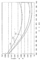
図16は、当該技術分野にてカットバック法として既知の方法により、光子運動計測器モデル2200を使用して行った信号のスペクトル減衰の測定結果を示すものである。曲線101は、本発明による光コアを製造するために使用したものと同一型式であるフォス及びルーセントでケーブル化される前の光ファイバにて行った測定中に記録された平均値に関するものである。曲線102は、本発明に従って製造したケーブルにて行われた数回の測定中に記録された平均値に関するものである。曲線103は、2つのポリマー材料層と、正接付着物とを有するように製造したケーブル(DPSケーブル)にて行われた数回の測定中に記録された平均値に関するものである。理解され得るように、本発明に従って製造したケーブルの場合、二重層及び正接付着物を有するように製造したケーブルと比較して、ケーブル化される前の光ファイバの値よりも平均的に小さく且つ該値に近い減衰値を得ることが可能であることが分かる。
【図面の簡単な説明】
【図1】 本発明に従って製造された光ケーブルの断面の縮尺通りでない部品を示す図である。
【図2】 図1によるケーブルの部品を形成する光コアに沿った概略図的な断面図である。
【図3】 図2による光コアの可能な変更例の断面図である。
【図4】 図1によるケーブルの光コア内における光ファイバの1つの軌線の概略図である。
【図5】 互いに隣接するように配置された、図2による光コアの2つの部分における同一の光ファイバが占める位置を示す図である。
【図6】 本発明の方法に従って光コアを製造する装置の概略図である。
【図7】 図6による装置の一部を形成する装置の概略図である。
【図8】 明確化のため部品を切欠いた、面VIII−VIIIに沿った図7による装置の縮尺通りでない断面図である。
【図9】 図7による装置に代えて図6による装置内で使用する設計とされた追加的な装置の図である。
【図10】 図6による装置内で使用される複数の駆動プーリーの所定の加工方向への配置を示す概略図である。
【図11】 図6による装置内で使用される押出し成形機の部分に沿った長手方向断面図の概略図である。
【図12】 面XII−XIIに沿った図11の細部の縮尺通りでない図である。
【図13】 図11による押出し成形機の部分を示す可能な変形例の長手方向断面図の概略図である。
【図14】 面XIV−XIVに沿った図13の詳細図である。
【図15】 PMDを測定する前に図6による装置を使用して製造された光コアにおける後続のケーブル製造ステップの効果を模擬するために使用される更なる装置の概略図である。
【図16】 本発明に従って製造されたケーブルにて行われる実験試験の結果を示す図である。[0001]
The present invention relates to an optical cable for telecommunications, and more particularly to a submarine optical cable for a multi-wavelength telecommunications apparatus that operates over a long distance and at a high transmission rate.
[0002]
Optical cables suitable for submarine applications typically include an optical core containing a plurality of optical fibers that transmit optical signals, and one or more external reinforcement and protective linings. The optical core is preferably of the type comprising a central support element and one or more polymer material layers around which the optical fiber is integrated at a fixed location.
[0003]
For submarine applications, the cable must operate in harsh environmental conditions, and in particular, the cable must withstand the effects of extremely high pressures and corrosive media. In addition, the cable must be able to withstand large mechanical stresses, particularly traction and bending stresses, applied to the cable during installation at sea and during operation with recovery. The forces generated in the cable as a result of these stresses can be transmitted to the optical fiber and adversely affect the attenuation of the transmitted signal.
[0004]
Conventionally, various forms for optical cables suitable for submarine application examples have been proposed.
Societa Cavi Pirelli S. et al. p.A. U.S. Pat. No. 4,744,935 is a structure that preferably includes a traction resistant core incorporated into the polymer material body at the radially innermost position, the polymer material A cable having a structure in which an optical fiber disposed in a loosely protected state is embedded in the body has been proposed. These optical fibers are arranged in an open spiral, that is, along a trajectory in which a portion having a first winding direction is alternated with a portion having an opposite winding direction.
[0005]
European Patent Application No. 851258 A1, in the name of “ALCATEL ALSTHOM COMPAGNIIE GENERALE D'ELECTRICITE”, the fiber is spirally wound around a central member, It relates to a fiber optic cable in which the fiber is incorporated in a covering layer that defines a single structure that prevents water penetration and flow with the central member. The optical fiber is an S or SZ helix (ie, wound in a closed or open helix). Since the fiber is disposed around the central member, a coating layer is extruded over the central member. This is done by an extrusion die that has a fiber guide hole around the central member and is capable of rotating in one direction or alternately in both directions.
[0006]
U.S. Pat. No. 4,541,970 in the name of AT & T BELL LAB extrudes a first thermoplastic elastomer layer around a previously heated reinforcing element , Placing the optical fiber in a helix, using a “planet motion” technique on the first elastomer layer, and extruding a second elastomer material layer onto the first elastomer layer A method for manufacturing a core of a submarine communication cable is proposed. The winding of the optical fiber in accordance with the “planetary operation” technique is performed by an apparatus consisting of a rotating cage involving a reel that holds the optical fiber and a suitable guide that directs the optical fiber from the cage to the extruder. In particular, the reel around which the optical fiber is unwound is supported in such a way that its axis remains parallel to a certain direction as the cage rotates. With this technique, the twisting force applied to the optical fiber is particularly reduced.
[0007]
U.S. Pat. No. 4,902,097 in the name of STC PLC describes the steps of extruding a thermoplastic elastomer layer around a central element, heating the surface to above its melting point, and a plurality of optical fibers. Additional techniques for manufacturing optical fibers have been proposed that include incorporating into the surface and extruding a second thermoplastic elastomer layer to cover the fiber. In this case, the optical fiber is partially incorporated in the first layer and partially incorporated in the second elastomer layer. The optical fibers are arranged at a winding angle equal to zero, i.e. they are arranged parallel to each other and to the central axis of the cable.
[0008]
U.S. Pat. No. 4,832,441 in the name of STC PLC proposes an optical cable suitable for submarine applications, wherein the cable is composed of a central filament, an acrylated and single extrusion process, In other words, it includes a plurality of optical fibers incorporated in a low melting point plastic material layer obtained by using a so-called one-shot process technique. In this case as well, the optical fibers are arranged at a winding angle equal to zero.
[0009]
US Pat. No. 5,440,659 in the name of AT & T Corp. includes applying a controlled twisting force to each of the optical fibers during the cable manufacturing process. An optical fiber cable manufacturing method has been proposed. The applied twisting force is uniform along the entire length of the optical fiber. An optical fiber is spirally wound around a first thermoplastic material layer extruded into the central element, and a further thermoplastic material layer is extruded into the optical fiber. A rotating cage similar to that used in the aforementioned US Pat. No. 4,541,970 is used to spiral the optical fiber along the helix, but the reel holding the optical fiber is It is fixed to itself or rotates in a controlled manner to control the twisting force applied to the optical fiber during the manufacturing process of the optical core.
[0010]
British Patent Application No. 2,303,938 in the name of STC Submarine Systems Limited relates to fiber optic cables and related manufacturing methods. The proposed method includes extruding a thermoplastic elastomer layer around a central element, curing the elastomer layer (by cooling), and placing a plurality of optical fibers along the cured elastomer. And extruding a further thermoplastic elastomer layer on top of the optical fiber. The optical fiber can be twisted around its own axis and / or wound along a spiral around the first layer before extruding additional layers. This twisting and / or winding process can be continuous or performed alternately at a predetermined angle.
[0011]
A technique for depositing an optical fiber on a cured elastomeric layer is described below as a “tangential deposition technique” for the convenience of this specification.
[0012]
Applicants have found that cables manufactured using the known methods described above are problematic in terms of signal attenuation and / or directional mode dispersion ("PMD").
[0013]
Attenuation of the optical power of signals in an optical cable is a particularly serious problem in long-distance optical telecommunications equipment. In such a device, it is necessary to use signal amplifiers placed at a predetermined distance (eg, a distance of several hundred kilometers) from each other to ensure accurate capture of the signal. These signal amplifiers are typically active fiber type optical amplifiers, preferably having a substantially flat amplification band within the transmission band. In a multiwavelength telecommunication device, the degree of attenuation of the signal in the optical cable depends on the wavelength, so that the amplifier of the telecommunication device as a whole receives the unequalized signal. To overcome this drawback, for example, the signals placed along the amplifier itself or along the line so that the optical power in the various communication channels (each of which has a respective wavelength associated with the channel) can be equalized. It is known to use an equalizer.
[0014]
As is known, to achieve accurate equalization, the spectral attenuation curve of the optical fiber needs to have a substantially constant and predictable slope within the transmission band. Overall, in a cable for optical telecommunication, the degree of attenuation of the transmitted signal is present in the cable, for example generated during the manufacturing process, during the cable unwinding process or during the process performed on the cable itself. Depends on the state of force Furthermore, when there is a micro bend in the optical fiber within the cable itself, the degree of signal attenuation increases.
[0015]
The applicant uses a tangential deposition technique (described in the above-mentioned British Patent Application No. 2,303,938) and uses two extruded material layers and a plurality of optical fibers disposed on the first layer. Has been found to cause problems related to attenuation as a result of the micro-bending effect of the optical fiber. Applicants have found that in practice, a microcavity of air is formed between the optical fiber and the first extruded layer while extruding the second layer into the first layer. thesemicroAs a result of the presence of the cavity, the optical fiber is locally displaced, which can cause micro bending of the fiber itself. As described above, the transmitted signal is attenuated as a result of micro-bending, and the degree of attenuation depends on the wavelength, so the spectral attenuation curve does not change slightly compared to the attenuation curve of the optical fiber before the cable is manufactured. Arise. This change in the spectral attenuation curve due to the manufacture of the cable introduces disadvantages because it introduces unpredictable factors regarding the transmission performance of the device that cannot be taken into account during the actual device design phase. This can result in undesired device behavior in terms of signal attenuation as a result of significant changes in the attenuation curve after cable manufacture, and can result in inefficient signal equalization within the device itself. There is.
[0016]
The applicant has also found that this optical cable also has problems associated with PMD. The PMD of a signal transmitted in an optical fiber is caused by a difference in group velocities when propagating in the orthogonal mode of the signal itself. In the case of a digital signal, this difference causes an interval outside the transmitted bits, and the signal deteriorates accordingly.
[0017]
The PMD in an optical fiber manufactured to a cable depends on a change in morphology that affects the optical fiber as a result of the cable manufacturing process. Overall, if the optical fiber is locally stressed, there will be a local delay between the orthogonal propagation modes within this band. The total delay introduced along the optical fiber will determine the PMD.
[0018]
More specifically, during various stages of manufacturing a cable, the applicant may apply radial stresses in the cable and extend over the entire length of the cable itself and deform the cross section of the optical fiber. I understood that. In particular, during the manufacturing process of the optical core, tension is “accumulated” inside the optical core, so that radial stress is continuously distributed substantially uniformly in an oblique direction over the cross section of the optical core itself. It becomes a state. As a result of this stress state, the optical fiber is deformed, thus increasing the PMD. Similar effects occur during subsequent processing, and during the normal construction process of the polyethylene sheath, due to radial stresses that occur during the pressing of the optical core.
[0019]
Applicant is responsible for PM arising from the manufacture of cableDIt has been found that a further factor that contributes to the increase in the area consists of, among other things, the elliptical geometric manufacturing defects of the external reinforcement and protective lining.
[0020]
In this case, the stress acts in the radial direction, but the stress mainly acts on the lateral portion of the cable where the deformation concentrates, so that the stress is not uniformly distributed in the oblique direction. These stresses can act on the optical fiber in a continuous or periodic manner depending on whether the fibers are placed parallel to each other or wound around a central element. In this latter case, the effect of stress depends on the periodic winding speed of the optical fiber itself.
[0021]
Applicant has described the case of a type of cable in which the optical fiber is partially incorporated into the first layer and partially incorporated into the second polymer layer (as described in US Pat. No. 4,902,097 mentioned above). During the extrusion of the second layer, it was found that the stress acting on the optical fiber applied a certain lateral pressure to the optical fiber, resulting in degradation of transmission characteristics related to PMD. .
[0022]
Overall, in addition, the Applicant is due to the different extrusion and cooling conditions affecting the two layer materials, and there are possible surface defects, or because of the form of the innermost layer after extrusion. As a result of an extrusion technique involving two successive stages, it has been found that forces typically occur in the region where the optical fiber is present. These forces can also increase due to the shrinkage phenomenon of the extruded material during cooling of the material itself or during cooling following the high temperature deposition of the lining outside the optical core.
[0023]
The only cable type according to the above reference with a single polymer material layer is that described in the above-mentioned US Pat. No. 4,832,441 in which the fibers are arranged parallel to each other. This form of arranging the fibers in parallel with each other (also described in the above-mentioned US Pat. No. 4,902,097) is that in this form the optical fiber is generally in a constant stress state, so that the point of PMD Is disadvantageous. In practice, stresses present during the manufacturing process and cable installation and due to external media always act along the same busbar of each optical fiber. For this reason, this optical fiber becomes a birefringence type, and therefore the performance deteriorates in terms of PMD.
[0024]
Applicants will note that if the optical fiber is wound along a helix but does not twist (eg, as described in the aforementioned US Pat. No. 4,541,970), that is, one of its busbars is When always oriented in the same direction, the above-mentioned problems caused by stress are not noticeable, but still win PMD. In this case, in practice, the stress periodically acts on the same busbar, thus causing birefringence along the cross section of the optical fiber (albeit to a lesser extent than in the case of parallel fibers), As a result, PMD increases.
[0025]
When the fiber wrap is “closed” spiral, ie always oriented in the same direction (eg as described in US Pat. No. 5,440,659 cited above in the name of AT & T). In addition, the applicant has found that there is a further disadvantage in terms of PMD when related to the non-zero twisted state of the optical fiber. This type of winding effectively creates photoelasticity and birefringence, resulting in an elastic twist in each optical fiber that increases and prevails in PMD. This phenomenon is described in, for example, ELECTRONIC LETTERS, October 1, 1981, Vol. 17, no. 20, page 725-726. J. et al. Barlow, D.C. N. Pyne, M.C. R. Hadley, R.A. J. et al. Mandfield's "manufactured single-mode fiber with negligible intrinsic birefringence and directional mode dispersion" described in the article named "Production of single-fibers with negligible intrinsic birefringence and polarization" . In this paper, the second clause from the end of
[0026]
Furthermore, if the twist angle of the optical fiber is set to be equal to the winding angle of the fiber itself around the central element (as proposed in US Pat. No. 5,440,659 mentioned above), Each is always exposed to radial stress along the same bus bar, resulting in a PMD that cannot be ignored. Even when this condition does not exist (ie, when the twist angle differs from the winding angle), a “uniform” winding condition (ie, a constant winding speed) results in the same busbar of the optical fiber, Periodic stresses will occur. Finally, winding as described above in the form of a closed spiral with twisting results in a continuous mechanical stress along the optical fiber that can structurally weaken the fiber itself. is there.
[0027]
According to the present invention, there is no discontinuous portion, and the PMD measured with the cable isOf the same model before being cabled110% of PMD measured with optical fiberIs less thanAn optical fiber cable is proposed in which the optical core wound along the trajectory of the “open” helix is fully incorporated in a polymer material layer having a selected degree of twist. In particular, the maximum local twist of the fiber is in the range of 0.05 times / m (or number of twists / m) to 1.5 times / m, preferably 0.1 times / m to 1 times / m. is there.
[0028]
Since the polymeric material layer is obtained using a single extrusion process, there are no discontinuities.
In the following, an “open” spiral or “SZ” trajectory is a cylindrical surface resulting from the combination of alternating rotational movement around the axis itself and translational movement in a direction parallel to the central axis. It is understood to mean a trajectory along Basically, this type of trajectory is different from a “closed” spiral trajectory, which means that the winding process around the central axis is not always directed in the same direction; This is because it is performed alternately in the counterclockwise direction.
[0029]
In the case of cables manufactured according to the invention, the disadvantages associated with optical fibers in which the fiber is placed between two extruded polymer layers are eliminated. In effect, the presence of a single polymer material layer in terms of signal attenuation eliminates the problem of optical fiber microbending that exists in optical cores manufactured using tangential deposition techniques. . In terms of PMD, the special arrangement of the optical fibers results in a reduction in the drawbacks mentioned above with respect to configurations consisting of fibers arranged in parallel and fibers arranged along a “closed” helix.
[0030]
Applicants have shown that it is particularly preferred for PMD to twist optically within a single polymer material layer and place the optical fiber along an “open” helix with a local predetermined twist. It was found to represent. In fact, this configuration results in a very irregular distribution of the stress acting on the cable over the surface of the optical fiber, thus reducing the difference in the group velocity of the orthogonal modes of the signal. Furthermore, the presence of alternating twists reduces the intrinsic PMD of the optical fiber depending on its core geometrical defects, and at the same time adversely affects the photoelastic effect leading to an increase in PMD as described above. It is possible not to give.
[0031]
Similarly, the method of manufacturing a cable according to the present invention, which forms the subject of the present invention, is particularly simple and rapid since only one extrusion process is required to manufacture the optical core, and also “planetary operation”. The cost is particularly low because complex machines such as technical cages are not required.
[0032]
According to a first aspect, the present invention is a method of manufacturing an optical cable comprising the step of incorporating at least one optical fiber into an extruded polymeric material in contact with a strand-like element, wherein the optical cable is incorporated into the polymeric material. The above steps
Arranging the optical fiber along an open spiral track;
Providing the optical fiber with a maximum local twist in the range of 0.05 times / m to 1.5 times / m, preferably in the range of 0.1 times / m to 1 times / m. The present invention relates to a manufacturing method characterized by
[0033]
Preferably, zero average twist is applied to the optical fiber.
The above steps incorporated into the polymer material are the following steps:
Supplying the strand-like element through an extrusion region in a predetermined supply direction;
Supplying the optical fiber at a predetermined distance from the strand-like element through the extrusion region;
Preferably, the polymer material is fed into the extrusion region so that the polymer material incorporates the strand-like element and the optical fiber.
[0034]
Preferably, a number of optical fibers ranging from 2 to 24 are incorporated into the polymer material.
Preferably, the step of placing each of the optical fibers along an open spiral track comprises the step of imparting an alternating twist to the strand-like element.
[0035]
The step of feeding the optical fiber through the extrusion region can comprise constraining the optical fiber in a twisted state upstream of the extrusion region at a predetermined distance from the extrusion region. The step of imparting a maximum local twist to the fiber comprises adjusting the constraint distance from the extrusion region for the maximum local twist.
[0036]
Preferably, the step of applying an alternating twist to the strand-shaped element comprises the step of applying a predetermined angular velocity and a predetermined maximum twist angle to the strand-shaped element, and supplying the strand-shaped element The step of translating the strand-like element at a predetermined feed rate, wherein the step of imparting a maximum local twist to the optical fiber comprises the angular velocity, the maximum twist angle or the maximum twist Adjusting the feed rate for local torsion.
[0037]
Preferably, the step of positioning the optical fiber along an open spiral trajectory comprises the step of relating a spatial inversion pitch of 0.5 m to 5 m with the trajectory.
[0038]
Furthermore, the step of feeding the optical fiber into the extrusion region comprises directing the optical fiber to the extrusion region by a support provided with a passageway and passing the strand-like element through its center. It is preferable that the method includes a step of transporting.
[0039]
According to its second aspect, the present invention provides an optical cable for telecommunications, substantially free of a central element in the form of a strand, at least one optical fiber, substantially discontinuous and A polymer material layer containing the central element and the optical fiber, the optical fiber being disposed along an open spiral trajectory and having a twist degree selected as follows: The measured PMDOf the same type before being cabled110% of PMD measured with optical fiberLess thanIt is related with the optical cable which has the twist grade chosen so that.
[0040]
The expression “layer substantially free of discontinuities” means that there is no separation surface (even if the type is the same), such as those resulting from subsequent and / or separate extrusion of the material, and the crystalline structure Or layers that do not differ in stress in the material.
[0041]
The optical fiber preferably has a maximum of 0.05 times / m to 1.5 times / m, more preferably 0.1 times / m to 1 times / m along each open spiral trajectory. Has a local twist.
[0042]
Further, the optical fiber has an average twist that is preferably equal to zero along each open spiral trajectory.
The cable preferably comprises a number of optical fibers ranging from 2 to 24.
[0043]
Preferably, the optical fiber has an absolute value of 360 ° or less along each open spiral trajectory.ofMaximum winding angle and the above maximum winding angle in absolute valueLess thanThe maximum torsion angle.
[0044]
The maximum twist angle is preferably in the range of 90 ° to 270 °.
Preferably, the optical fiber has a uniform polymer material thickness equal to or greater than 0.10 mm or equal to 0.10 mm.
[0045]
The open spiral trajectory preferably has an inversion pitch in the range of 0.5 m to 5 m.
Preferably, the cable comprises a plurality of optical fibers that define a ring of optical fibers that are equidistant from each other and arranged at the same distance from the axis of the cable.
[0046]
The distance of the optical fiber from the axis is in the range of 0.4 mm to 1.2 mm.
Alternatively, the cable is equidistant from each other and a first ring of optical fibers disposed at a first distance from the cable axis and is equidistant from the first distance. A plurality of optical fibers defining a second ring of optical fibers disposed at a second distance from the long axis.
[0047]
In this case, the first distance is preferably in the range of 0.4 mm to 0.8 mm, and the second distance is preferably in the range of 0.9 mm to 1.2 mm.
The layer of polymeric material preferably has a thickness in the range of 0.9 mm to 1.5 mm.
[0048]
The central element preferably has a diameter in the range of 0.5 mm to 0.7 mm.
The optical fiber is preferably 400 μmLess than, More preferably 270 μmLess thanHas an outer diameter of
[0049]
Preferably, the polymeric material has a flexural modulus in the range of 20 Mpa to 70 Mpa, a Shore hardness D factor in the range of 15 to 70, and a melt flow index in the range of 5 to 15.
[0050]
Preferably, the cable comprises a sheath disposed around the polymer material layer, the sheath being a polyalkylene terephthalate.-It is made of a material selected from the group consisting of G, polyolefin and polyamide.
[0051]
Further information regarding the present invention can be obtained from the following description of non-limiting embodiments with reference to the accompanying drawings.
FIG. 1 shows a cross-sectional view of a submarine
[0052]
The
[0053]
The
[0054]
A plurality of reinforcing elements 7 a, 7 b, 7 c, which are preferably strand-like elements made of steel, are provided around the
The first having a first diameter and arranged to contact each other so as to provide a self-supporting structure that defines a first reinforcing layer 8 outside the
A second group of reinforcing elements 7b having a second diameter smaller than the diameter of the first group and arranged outside the elements of the first group 7a;
A second reinforcing layer 9 having a third diameter smaller than the diameter of the second group and arranged outside the elements of the first group 7a and on the outside of the reinforcing layer 8 together with the second group 7b. A second group 7b of elements and a third group of reinforcing elements 7c arranged alternately are provided so as to be definable.
[0055]
The reinforcing element 7c is arranged at an angular position corresponding to the angular position of the reinforcing element 7a, and the second reinforcing layer 9 has a substantially cylindrical outer envelope that is tangent to both the reinforcing element 7b and the reinforcing element 7c.
[0056]
The assembly consisting of the two reinforcing layers 8, 9 defines a structure known in the art as a "Warlington" structure.
[0057]
Alternatively, the reinforcing elements may be arranged in other forms, i.e. in one or more rows depending on the state of use.
In addition, the
[0058]
In the absence of further lining, the outer diameter of the
[0059]
The
[0060]
In FIG. 2, the
[0061]
The
[0062]
The
[0063]
The
[0064]
In the variant illustrated in FIG. 3 for an
[0065]
For each of the possible configurations discussed herein, the distance of each of the
[0066]
FIG. 4 shows one trajectory of the
[0067]
Each of the
[0068]
In addition to the twist angle β, it is possible to define a local twist corresponding to dβ / dx (this value is in rad / m or equivalent manner in revolutions / m or per unit length). Where x is the spatial coordinate measured along the
[0069]
In the
[0070]
Since the twist angle β is variable and the absolute value is equal to or less than the winding angle α or equal to the winding angle α, it is possible to prevent continuous or periodic stress from being applied to the surface portion of the
[0071]
Further advantages in terms of PMD are provided by the special winding type used. In fact, since an SZ type winding configuration is used, each of the
[0072]
Referring to FIG. 6,
[0073]
The
[0074]
The
[0075]
The
A
A known type of
And a twisting
[0076]
The twisting
[0077]
The twisting
[0078]
The
[0079]
The
[0080]
The
[0081]
As illustrated in the cross-sectional view of FIG. 8, each pair of first and
[0082]
FIG. 9 shows a twisting
[0083]
The
[0084]
Referring again to FIG. 6, each of the
[0085]
The
[0086]
Referring to FIG. 10, the
[0087]
The extruded
[0088]
FIG. 11 shows an
[0089]
The
[0090]
The
[0091]
Referring to FIGS. 11 and 12, the
[0092]
The
[0093]
The
[0094]
Each of the
[0095]
In FIGS. 13 and 14, different embodiments of a central body designed for the case where the
[0096]
Referring again to FIG. 6, the
[0097]
Since the
[0098]
The
[0099]
The
[0100]
Referring to FIG. 15,
[0101]
The
[0102]
Below, the manufacturing method of the
[0103]
The
[0104]
The
[0105]
Due to the alternating twisting action imparted to the
[0106]
While twisting the
[0107]
The maximum local twist that can be imparted to the
[0108]
According to one possible variant not shown, the
[0109]
The
[0110]
Thereafter, when the optical core passes through the
[0111]
Experimental result
A manufacturing apparatus 20 (FIG. 6) was used to manufacture different types of
[0112]
[Table 1]
The
[0114]
The
The polymer material used for the production of the
[0115]
The process parameters common to all the individual processes for producing the
The
[0116]
The
The dimension parameters (FIG. 11) of the
[0117]
Diameter of opening 72: 2.9 mm
Length of opening 72: 4 mm
The length of the central body 69: 15 mm
The outer diameter of the
In addition, the pressure when the polymer material was injected through the
[0118]
For direct comparison with other manufacturing techniques, different types of optical cores were manufactured using the same materials and the
[0119]
A second type of optical core different from that according to the invention uses a technique corresponding to that described in EP 97121295.6 filed on Dec. 4, 1997 in the name of the applicant. And manufactured. This technique adhered the optical fiber tangentially to the previously lined support and preheated to an appropriate temperature and in equilibrium with the axis of the support. The optical cores manufactured according to the above-described technique are denoted by the word DPS with progressive numbers. In particular, by this technique, an optical core DPS1 composed of the same optical fiber as the optical core SZ1, an optical core DPS2 composed of the same optical fiber as the optical core SZ2, and an optical core DPS3 composed of the same optical fiber as the optical cores SZ3 and SZ4 are obtained. Manufactured using this technique.
[0120]
In order to confirm the effect of cable manufacture in terms of PMD, an apparatus 90 (FIG. 15) that can simulate the effect of cable manufacture before measuring PMD for each optical core sample of 900 m in length. Used to process. This processing step was performed using an optical core portion having a length of 900 m.
[0121]
Processing by the
Tensile force during unwinding: 3 kg
Tensile force during storage: 3kg
Line speed: 2.5m / min
Temperature in the heating furnace 92: 100 ° C.
Storage diameter on reel 96 (1 turn): 1 m
In order to confirm only the effect of the thermal effects of the cable manufacturing during subsequent PMD measurements, each of the optical cores 900 m long and equal to the previous sample is further switched off in the
[0122]
Tensile force during unwinding: 3 kg
Tensile force during storage: 3kg
Line speed: 10m / min
Storage diameter on reel 96 (1 turn): 1 m
Each sample prepared using the two methods described above was measured on PMD after being stored on a reel. PMD measurements on samples exposed to a temperature of 100 ° C. are shown below at [100 ° C.], while measurements made on samples stored at 20 ° C. are shown below at [20 ° C.].
[0123]
All PMD measurements were performed at a wavelength of 1550 nm using an interferometer model IQ206 for PMD measurement manufactured by the EXFO company and comprising:
Light source IQ2100;
Selector IQ5550;
Analyzer 5500
The PMD measurement results are listed in Table 2, Table 3 and Table 4 below. In this case, the optical cores made of the same type of optical fiber are grouped together. In particular, the average and maximum values of PMD for the optical fibers used and the average and maximum values for [20 ° C.] and [100 ° C.] for the measurements are listed in Table 2, Table 3 and Table 4, respectively. For purposes of the present invention, the PMD value of an optical fiber is 1 km long and is measured at the portion of the optical fiber wound on a reel with zero tension and a single layer.
[0124]
[Table 2]
[Table 3]
[Table 4]
Examining the results listed in Table 2, Table 3 and Table 4, the optical core manufactured according to the present invention is significantly improved in terms of PMD compared to the optical core manufactured using the other techniques described above. It can be understood that it has a high performance. Comparing the test conducted at 20 ° C. with the test conducted at 100 ° C., it can be seen that the effect of structural shrinkage of the optical core after heat treatment at 100 ° C. is of a particularly limited nature. Furthermore, it can be seen that in the case of a winding angle of 360 ° or more, the result obtained at an angle of about 360 ° is not significantly improved.
[0128]
SZ2 and SZ5 type optical cores, and CABLESZ2And CABLESZ5The PMD of the optical cable of the type shown in FIG. 1 obtained with the optical core shown in FIG. The measured PMD values are listed in Table 5 below.
[0129]
[Table 5]
The results in Table 5 confirm the results obtained before that. In particular, from the data listed in Table 5, the PMD measured with the cable according to the present invention is the same model as that used with the cable.And before being cabled110% of PMD when measured with optical fiberLess thanIt turns out that it is.
[0131]
FIG. 16 shows the result of measurement of spectral attenuation of a signal performed using the photon motion measuring instrument model 2200 by a method known as a cutback method in the technical field.
[Brief description of the drawings]
FIG. 1 shows parts not to scale in cross section of an optical cable manufactured in accordance with the present invention.
2 is a schematic cross-sectional view along the optical core forming the components of the cable according to FIG. 1;
FIG. 3 is a cross-sectional view of a possible modification of the optical core according to FIG.
4 is a schematic view of one track of the optical fiber in the optical core of the cable according to FIG. 1;
5 shows the position occupied by the same optical fiber in two parts of the optical core according to FIG. 2 arranged adjacent to each other. FIG.
FIG. 6 is a schematic view of an apparatus for producing an optical core according to the method of the present invention.
7 is a schematic view of an apparatus forming part of the apparatus according to FIG. 6;
8 is a cross-sectional view, not to scale, of the device according to FIG. 7 along plane VIII-VIII, with parts cut away for clarity.
9 is a diagram of an additional device designed to be used in the device according to FIG. 6 instead of the device according to FIG.
10 is a schematic view showing the arrangement of a plurality of drive pulleys used in the apparatus according to FIG. 6 in a predetermined processing direction.
11 is a schematic view of a longitudinal section along a part of an extruder used in the apparatus according to FIG. 6;
12 is a drawing not to scale of the detail of FIG. 11 along plane XII-XII.
13 is a schematic view of a longitudinal section of a possible variant showing the part of the extruder according to FIG.
14 is a detailed view of FIG. 13 along the plane XIV-XIV.
15 is a schematic diagram of a further apparatus used to simulate the effect of a subsequent cable manufacturing step on an optical core manufactured using the apparatus according to FIG. 6 before measuring PMD.
FIG. 16 shows the results of an experimental test performed on a cable manufactured according to the present invention.
Claims (29)
ポリマー材料中に組み込む前記ステップが、
前記光ファイバ(3)をSZ螺旋軌線に沿って配置するステップと、
前記光ファイバ(3)に対し、0.05回/m乃至1.5回/mの範囲の最大の局部的捩れを付与するステップであって、それにより、前記ケーブルにて測定したPMDが、同一型式でケーブル化される前の光ファイバにて測定したPMDの110%未満となる、局部的捩れを付与するステップとを備える、製造方法。Comprising at least one step of incorporating an optical fiber (3) in a polymeric material which is extruded in contact with the strand-like element (4), in the manufacturing method of the optical cable (1),
The step of incorporating into the polymer material comprises:
Arranging the optical fiber (3) along an SZ spiral trajectory ;
The optical fiber with respect to (3), comprising the steps of applying a 0.05 turns / m and 1.5 turns / m range maximum of local twisted, whereby, PMD is measured at said cable, less than 110% of the PMD measured at the previous optical fibers cable of the same type, Ru and a step of applying localized twisting method.
ポリマー材料中に組み込む前記ステップが、前記光ファイバ(3)に対し、0.1回/m乃至1回/mの範囲の最大の局部的捩れを付与するステップを備える、方法。The method according to claim 1, wherein
The step of incorporating into the polymer material is, the optical fiber with respect to (3), Ru with the largest step of imparting localized twisting in the range of 0.1 times / m to 1 turns / m, method.
ポリマー材料中に組み込む前記ステップが、前記光ファイバ(3)に対し、零平均捩れ(zero mean torsion)を付与するステップを備える、方法。The method according to claim 1, wherein
The step of incorporating in a polymeric material is, to the optical fiber (3), Ru comprising the step of applying a zero-mean twist (zero mean torsions) method.
ポリマー材料中に組み込む前記ステップが、
前記ストランド状要素(4)を所定の供給方向に向けて、押出し成形領域(77)を通じて供給するステップと、
前記光ファイバ(3)を前記押出し成形領域を通じて、前記ストランド状要素(4)から所定の距離にて供給するステップと、
前記ポリマー材料を前記押出し成形領域(77)内に供給し、前記ポリマー材料が前記ストランド状要素及び前記光ファイバを包み込むようにするステップとを備える、方法。The method according to claim 1, wherein
The step of incorporating into the polymer material comprises:
Feeding the strand-like element (4) through an extrusion region (77) in a predetermined feeding direction;
Supplying the optical fiber (3) at a predetermined distance from the strand-like element (4) through the extrusion region;
The polymeric material is supplied to the extrusion area (77) in said polymeric material Ru and a step of the enveloping said strand-like element and the optical fiber, the method.
ポリマー材料中に組み込む前記ステップが、2乃至24の範囲の光ファイバを前記ポリマー材料中に組み込むステップを含む、方法。The method according to claim 1, wherein
The step of incorporating in a polymeric material is 2 to including the step of incorporating the optical fiber in the range of 24 in the polymer material, method.
前記光ファイバ(3)をSZ螺旋軌線に沿って配置する前記ステップが、前記ストランド状要素(4)に対し交番的な撚りを付与するステップを備える、方法。The method according to claim 4, wherein
It said step said optical fiber and (3) to place along the SZ spiral trajectory is, Ru comprises a step of imparting alternating twist to said strand-like element (4), methods.
前記光ファイバ(3)を前記押出し成形領域を通じて、供給する前記ステップが、前記押出し成形領域(77)から所定の距離の前記押出し成形領域の上流にて、前記光ファイバを捩れ状態に拘束する(62)ステップを備え、
前記光ファイバ(3)に対し最大の局部的な捩れを付与する前記ステップが、前記最大の局部的な捩れに対し押出し成形領域からの前記拘束距離を調節するステップを備える、方法。The method according to claim 4, wherein
The step of feeding the optical fiber (3) through the extrusion region constrains the optical fiber in a twisted state upstream of the extrusion region at a predetermined distance from the extrusion region (77) ( 62) comprising steps,
It said step of applying a maximum local torsion to said optical fiber (3) is, Ru comprises the step of said maximum local torsion to regulate the constraint distance from extrusion area, method.
前記ストランド状要素(4)に交番的な撚りを付与する前記ステップが、前記ストランド状要素に対し、所定の角速度(ω)及び所定の最大の捩れ角度(α´MAX)を付与するステップを備え、
前記ストランド状要素を供給する前記ステップが、該ストランド状要素を所定の供給速度(v)にて変位させるステップを備え、
前記光ファイバ(3)に対し最大の局部的な捩れを付与する前記ステップが、前記角速度、前記最大の捩れ角度又は該最大の局部的な捩れに対する前記供給速度を調節するステップを備える、方法。The method according to claim 6.
Wherein said step of imparting alternating twist to the strand-like element (4) is, with respect to the strand-like element, comprising a step of imparting a predetermined angular velocity (omega) and a predetermined maximum angle of twist ([alpha] 'MAX) ,
The step of supplying the strand-shaped element comprises displacing the strand-shaped element at a predetermined supply speed (v);
It said step of applying a maximum local torsion to said optical fiber (3) is the angular velocity, Ru comprising the step of adjusting the feed rate for the partially twisted in the largest twist angle or outermost large method .
前記光ファイバ(3)をSZ螺旋軌線に沿って配置する前記ステップが、0.5m乃至5mの空間的反転ピッチ(P)を前記軌線と関係させるステップを備える、方法。The method according to claim 1, wherein
Said step of placing said optical fiber (3) along the SZ spiral trajectory is, spatial inversion pitch of 0.5m to 5m (P) is Ru comprising the step of relation with the trajectory method.
前記光ファイバ(3)を前記押出し成形領域(77)内に供給する前記ステップが、通路(71)が設けられ且つ前記ストランド状要素(4)をその中央を貫通するように通過させる支持体(69)によって、前記光ファイバを前記押出し成形領域に向けて搬送するステップを備える、方法。The method according to claim 4, wherein
The step of feeding the optical fiber (3) into the extrusion region (77) is provided with a passage (71) and a support (Pass through the center of the strand-like element (4)). 69) , transporting the optical fiber toward the extrusion zone.
実質的にストランド状の中央要素(4)と、少なくとも1つの光ファイバ(3)と、実質的に不連続部分が存在せず且つ前記中央要素(4)及び前記光ファイバを内蔵するポリマー材料層(5)とを備え、
該光ファイバ(3)が、SZ螺旋軌線に沿って配置され、また前記光ファイバ(3)に対し、0.05回/m乃至1.5回/mの範囲の最大の局部的捩れを有し、それにより、前記ケーブルにて測定したPMDが、ケーブル化される前の同一型式の光ファイバにて測定したPMDの110%未満となる、光ケーブル。In the optical cable (1),
A substantially strand-shaped central element (4), at least one optical fiber (3), and a polymer material layer substantially free of discontinuities and containing the central element (4) and the optical fiber (5)
The optical fiber (3) is arranged along the SZ spiral trajectory and has a maximum local twist in the range of 0.05 times / m to 1.5 times / m with respect to the optical fiber (3). An optical cable having a PMD measured with the cable that is less than 110% of the PMD measured with the same type of optical fiber before being cabled .
前記光ファイバ(3)が、それぞれのSZ螺旋軌線に沿って、0.05回/m乃至1.5回/mの範囲の最大の局部的捩れを有する、ケーブル。Cable according to claim 11,
Cable wherein the optical fiber (3) has a maximum local twist in the range of 0.05 times / m to 1.5 times / m along each SZ helical trajectory .
前記光ファイバ(3)が、それぞれのSZ螺旋軌線に沿って、0.1回/m乃至1回/mの範囲の最大の局部的捩れを有する、ケーブル。Cable according to claim 11,
Cable wherein the optical fiber (3) has a maximum local twist in the range of 0.1 turns / m to 1 turns / m along each SZ helical trajectory .
前記光ファイバ(3)が、それぞれのSZ螺旋軌線に沿って零平均捩れを有する、ケーブル。Cable according to claim 11,
Cable wherein said optical fiber (3) has a zero mean twist along its respective SZ spiral trajectory .
2乃至24の範囲の多数の光ファイバを備える、ケーブル。Cable according to claim 11,
A cable comprising a number of optical fibers ranging from 2 to 24.
前記光ファイバ(3)が、それぞれのSZ螺旋軌線に沿って、絶対値にて360゜以下の最大の巻き角度(αMAX)と、絶対値にて前記最大巻き角度未満の最大の捩れ角度(βMAX)とを有する、ケーブル。Cable according to claim 11,
The optical fiber (3) has a maximum winding angle (α MAX ) of 360 ° or less in absolute value and a maximum twist angle of less than the maximum winding angle in absolute value along each SZ spiral trajectory. A cable having (β MAX ).
前記最大の捩れ角度(βMAX)が90゜乃至270゜の範囲にある、ケーブル。Cable according to claim 16,
A cable wherein the maximum twist angle (β MAX ) is in the range of 90 ° to 270 °.
0.10mm以上の均一なポリマー材料の厚さが前記光ファイバ(3)の周りに提供される、ケーブル。Cable according to claim 11,
A cable, wherein a uniform polymer material thickness of 0.10 mm or more is provided around the optical fiber (3).
前記SZ螺旋軌線が0.5m乃至5mの範囲の反転ピッチ(P)を有する、ケーブル。Cable according to claim 11,
The cable, wherein the SZ spiral trajectory has a reversal pitch (P) in the range of 0.5 m to 5 m.
互いに等距離にあり且つ前記ケーブル(1)の軸線(10)から同一の距離に配置された光ファイバのリングを画定する複数の光ファイバ(3)を備える、ケーブル。Cable according to claim 11,
Cable comprising a plurality of optical fibers (3) that are equidistant from each other and that define a ring of optical fibers arranged at the same distance from the axis (10) of said cable (1).
前記軸線(10)からの前記光ファイバ(3)の前記距離が、0.4mm乃至1.2mmの範囲にある、ケーブル。Cable according to claim 20,
The cable, wherein the distance of the optical fiber (3) from the axis (10) is in the range of 0.4 mm to 1.2 mm.
互いに等距離にあり且つ前記ケーブル(1)の軸線(10)から第一の距離に配置された光ファイバの第一のリング(15)と、互いに等距離にあり且つ前記第一の距離よりも長い前記軸線(10)からの第二の距離に配置された光ファイバの第二のリング(16)とを画定する複数の光ファイバ(3)を備える、ケーブル。Cable according to claim 11,
The first ring (15) of optical fibers that are equidistant from each other and arranged at a first distance from the axis (10) of the cable (1), and equidistant from each other and more than the first distance A cable comprising a plurality of optical fibers (3) defining a second ring (16) of optical fibers disposed at a second distance from said long axis (10).
前記第一の距離が0.4mm乃至0.8mmの範囲にあり、前記第二の距離が0.9mm乃至1.2mmの範囲にある、ケーブル。Cable according to claim 22,
The cable wherein the first distance is in the range of 0.4 mm to 0.8 mm and the second distance is in the range of 0.9 mm to 1.2 mm.
前記ポリマー材料(5)の層が0.9mm乃至1.5mmの範囲の厚さを有する、ケーブル。Cable according to claim 11,
Cable, wherein the layer of polymer material (5) has a thickness in the range of 0.9 mm to 1.5 mm.
前記中央要素(4)が0.5mm乃至0.7mmの範囲の直径を有する、ケーブル。Cable according to claim 11,
Cable with said central element (4) having a diameter in the range of 0.5 mm to 0.7 mm.
前記光ファイバ(3)が400μm未満の外径を有する、ケーブル。Cable according to claim 11,
Cable with said optical fiber (3) having an outer diameter of less than 400 μm.
前記光ファイバ(3)が270μm未満の外径を有する、ケーブル。Cable according to claim 11,
Cable with optical fiber (3) having an outer diameter of less than 270 μm.
前記ポリマー材料が、20Mpa乃至70Mpaの範囲の曲げ弾性率、15乃至70の範囲のショア硬さDファクタ、及び5乃至15の範囲のメルトフロー指数を有する、ケーブル。Cable according to claim 11,
A cable wherein the polymeric material has a flexural modulus in the range of 20 Mpa to 70 Mpa, a Shore hardness D factor in the range of 15 to 70 , and a melt flow index in the range of 5 to 15.
前記ポリマー材料(5)層の周りに配置されたシース(6)を備え、
該シース(6)が、ポリアルキレンテレフタレート、ポリオレフィン及びポリアミドから成る群から選ばれた材料で出来ている、ケーブル。Cable according to claim 11,
Comprising a sheath (6) disposed around the polymeric material (5) layer;
The sheath (6) is, polyalkylene reflex sauce over bets are made of a material selected from the group consisting of polyolefins and polyamides, cable.
Applications Claiming Priority (5)
| Application Number | Priority Date | Filing Date | Title |
|---|---|---|---|
| EP99106565 | 1999-03-31 | ||
| US12788599P | 1999-04-05 | 1999-04-05 | |
| US99106565.7 | 1999-04-05 | ||
| US60/127,885 | 1999-04-05 | ||
| PCT/EP2000/002400 WO2000060393A1 (en) | 1999-03-31 | 2000-03-17 | Optical cable for telecommunications |
Publications (3)
| Publication Number | Publication Date |
|---|---|
| JP2002541509A JP2002541509A (en) | 2002-12-03 |
| JP2002541509A5 JP2002541509A5 (en) | 2009-11-05 |
| JP4583605B2 true JP4583605B2 (en) | 2010-11-17 |
Family
ID=26152949
Family Applications (1)
| Application Number | Title | Priority Date | Filing Date |
|---|---|---|---|
| JP2000609826A Expired - Fee Related JP4583605B2 (en) | 1999-03-31 | 2000-03-17 | Optical cable for telecommunications |
Country Status (11)
| Country | Link |
|---|---|
| EP (1) | EP1200864B1 (en) |
| JP (1) | JP4583605B2 (en) |
| AR (1) | AR030670A1 (en) |
| AT (1) | ATE405856T1 (en) |
| AU (1) | AU765322B2 (en) |
| BR (1) | BR0009454A (en) |
| CA (1) | CA2368817C (en) |
| DE (1) | DE60039987D1 (en) |
| ES (1) | ES2312336T3 (en) |
| NZ (1) | NZ514395A (en) |
| WO (1) | WO2000060393A1 (en) |
Families Citing this family (16)
| Publication number | Priority date | Publication date | Assignee | Title |
|---|---|---|---|---|
| JP2002277699A (en) * | 2001-01-11 | 2002-09-25 | Occ Corp | Optical fiber unit, method and device for manufacturing optical fiber unit |
| GB2409908C (en) * | 2002-08-10 | 2011-07-13 | Emtelle Uk Ltd | Signal transmitting cable |
| GB0313018D0 (en) | 2002-08-10 | 2003-07-09 | Emtelle Uk Ltd | Signal transmitting cable |
| DE60231440D1 (en) * | 2002-10-30 | 2009-04-16 | Prysmian Spa | TELECOMMUNICATION CABLE WITH SPLICE AND METHOD FOR ITS MANUFACTURE |
| JP4810174B2 (en) * | 2004-10-05 | 2011-11-09 | 宇部日東化成株式会社 | Method and apparatus for manufacturing spiral spacer |
| JP4670523B2 (en) * | 2005-07-19 | 2011-04-13 | 住友電気工業株式会社 | Optical cable |
| KR101334077B1 (en) * | 2005-10-04 | 2013-11-28 | 우베 에쿠시모 가부시키가이샤 | Method and device for manufacturing spiral spacer |
| JP2007108424A (en) * | 2005-10-13 | 2007-04-26 | Sumitomo Electric Ind Ltd | Optical cable |
| WO2007113924A1 (en) * | 2006-04-04 | 2007-10-11 | Ube-Nitto Kasei Co., Ltd. | Method and device for manufacturing spiral spacer |
| FR2939911B1 (en) * | 2008-12-12 | 2011-04-08 | Draka Comteq France | SOLDERED OPTICAL FIBER, TELECOMMUNICATION CABLE COMPRISING MULTIPLE OPTICAL FIBERS AND METHOD FOR MANUFACTURING SUCH A FIBER |
| KR102005118B1 (en) * | 2013-03-18 | 2019-07-29 | 엘에스전선 주식회사 | Superconducting cable |
| FI125568B (en) | 2014-06-03 | 2015-11-30 | Rosendahl Nextrom Oy | Apparatus for processing optical fibers |
| PL3281051T3 (en) * | 2015-04-09 | 2022-09-26 | Prysmian S.P.A. | A method of sz stranding flexible micromodules |
| JP6981856B2 (en) * | 2017-11-15 | 2021-12-17 | 株式会社フジクラ | Manufacturing method of optical fiber tape and intermittent connection type optical fiber tape |
| EP3928138A1 (en) * | 2019-02-20 | 2021-12-29 | Hampidjan HF. | Improved high resolution headline sonar cable |
| WO2021132376A1 (en) * | 2019-12-27 | 2021-07-01 | 昭和電線ケーブルシステム株式会社 | Loose tube-type optical cable production device and production method |
Family Cites Families (8)
| Publication number | Priority date | Publication date | Assignee | Title |
|---|---|---|---|---|
| IT1185951B (en) * | 1985-09-27 | 1987-11-18 | Pirelli Cavi Spa | PROCEDURE AND LINE FOR THE PRODUCTION OF CABLES |
| JPH0713688B2 (en) * | 1987-01-16 | 1995-02-15 | 住友電気工業株式会社 | Fiber optic cable |
| JPH0713687B2 (en) * | 1987-01-16 | 1995-02-15 | 住友電気工業株式会社 | Fiber optic cable |
| US5440659A (en) * | 1993-09-30 | 1995-08-08 | At&T Corp. | Method for fabricating a fiber optic cable having improved polarization mode dispersion (PMD) performance |
| JPH07168068A (en) * | 1993-12-14 | 1995-07-04 | Hitachi Cable Ltd | Optical fiber unit and manufacture thereof |
| JPH0850208A (en) * | 1994-08-08 | 1996-02-20 | Furukawa Electric Co Ltd:The | Dispersion compensator |
| JPH10160945A (en) * | 1996-11-29 | 1998-06-19 | Fujikura Ltd | S-z slot type optical fiber cable |
| FR2757643B1 (en) * | 1996-12-23 | 1999-01-22 | Alsthom Cge Alcatel | FIBER OPTICAL, FLEXIBLE AND HIGH RESISTANCE CABLE |
-
2000
- 2000-03-17 BR BR0009454-4A patent/BR0009454A/en not_active Application Discontinuation
- 2000-03-17 JP JP2000609826A patent/JP4583605B2/en not_active Expired - Fee Related
- 2000-03-17 ES ES00916971T patent/ES2312336T3/en not_active Expired - Lifetime
- 2000-03-17 NZ NZ514395A patent/NZ514395A/en not_active IP Right Cessation
- 2000-03-17 EP EP00916971A patent/EP1200864B1/en not_active Expired - Lifetime
- 2000-03-17 AU AU38127/00A patent/AU765322B2/en not_active Ceased
- 2000-03-17 CA CA002368817A patent/CA2368817C/en not_active Expired - Fee Related
- 2000-03-17 WO PCT/EP2000/002400 patent/WO2000060393A1/en active IP Right Grant
- 2000-03-17 AT AT00916971T patent/ATE405856T1/en not_active IP Right Cessation
- 2000-03-17 DE DE60039987T patent/DE60039987D1/en not_active Expired - Lifetime
- 2000-03-31 AR ARP000101472A patent/AR030670A1/en active IP Right Grant
Also Published As
| Publication number | Publication date |
|---|---|
| CA2368817A1 (en) | 2000-10-12 |
| EP1200864A1 (en) | 2002-05-02 |
| AR030670A1 (en) | 2003-09-03 |
| WO2000060393A1 (en) | 2000-10-12 |
| CA2368817C (en) | 2009-02-17 |
| NZ514395A (en) | 2002-07-26 |
| AU765322B2 (en) | 2003-09-18 |
| JP2002541509A (en) | 2002-12-03 |
| BR0009454A (en) | 2002-01-08 |
| EP1200864B1 (en) | 2008-08-20 |
| ATE405856T1 (en) | 2008-09-15 |
| DE60039987D1 (en) | 2008-10-02 |
| ES2312336T3 (en) | 2009-03-01 |
| AU3812700A (en) | 2000-10-23 |
Similar Documents
| Publication | Publication Date | Title |
|---|---|---|
| JP4583605B2 (en) | Optical cable for telecommunications | |
| EP1600801B2 (en) | Protective covering for optical fiber cable | |
| US4541970A (en) | Method for fabricating a cable core including optical fibers | |
| US6853780B1 (en) | Optical cable for telecommunications | |
| FI83914B (en) | FOERFARANDE OCH UTRUSTNING FOER TILLVERKNING AV ETT FLERFIBRIGT OPTISKT LEDARELEMENT. | |
| US6827884B2 (en) | Method and apparatus for manufacturing an optical fibre cable and cable so manufactured | |
| US6500365B1 (en) | Process for the manufacture of an optical core for a telecommunications cable | |
| EP1036344B1 (en) | Process for the manufacture of an optical core for a telecommunications cable | |
| EP1141759B1 (en) | Method and apparatus for manufacturing an optical fibre cable and cable so manufactured | |
| US6625365B2 (en) | Overcoated fiber for use in optical fiber cable | |
| US6554938B1 (en) | Over-coated optical fiber and manufacturing method thereof | |
| CN116184592B (en) | Submarine optical cable and preparation method thereof | |
| GB2409909A (en) | Signal transmitting cable |
Legal Events
| Date | Code | Title | Description |
|---|---|---|---|
| A621 | Written request for application examination |
Free format text: JAPANESE INTERMEDIATE CODE: A621 Effective date: 20061025 |
|
| A711 | Notification of change in applicant |
Free format text: JAPANESE INTERMEDIATE CODE: A711 Effective date: 20080806 |
|
| RD03 | Notification of appointment of power of attorney |
Free format text: JAPANESE INTERMEDIATE CODE: A7423 Effective date: 20081106 |
|
| A131 | Notification of reasons for refusal |
Free format text: JAPANESE INTERMEDIATE CODE: A131 Effective date: 20090518 |
|
| A601 | Written request for extension of time |
Free format text: JAPANESE INTERMEDIATE CODE: A601 Effective date: 20090817 |
|
| A602 | Written permission of extension of time |
Free format text: JAPANESE INTERMEDIATE CODE: A602 Effective date: 20090824 |
|
| A521 | Request for written amendment filed |
Free format text: JAPANESE INTERMEDIATE CODE: A523 Effective date: 20090909 |
|
| A524 | Written submission of copy of amendment under article 19 pct |
Free format text: JAPANESE INTERMEDIATE CODE: A524 Effective date: 20090909 |
|
| A521 | Request for written amendment filed |
Free format text: JAPANESE INTERMEDIATE CODE: A821 Effective date: 20090909 |
|
| TRDD | Decision of grant or rejection written | ||
| A01 | Written decision to grant a patent or to grant a registration (utility model) |
Free format text: JAPANESE INTERMEDIATE CODE: A01 Effective date: 20100803 |
|
| A01 | Written decision to grant a patent or to grant a registration (utility model) |
Free format text: JAPANESE INTERMEDIATE CODE: A01 |
|
| A61 | First payment of annual fees (during grant procedure) |
Free format text: JAPANESE INTERMEDIATE CODE: A61 Effective date: 20100901 |
|
| R150 | Certificate of patent or registration of utility model |
Free format text: JAPANESE INTERMEDIATE CODE: R150 |
|
| FPAY | Renewal fee payment (event date is renewal date of database) |
Free format text: PAYMENT UNTIL: 20130910 Year of fee payment: 3 |
|
| R250 | Receipt of annual fees |
Free format text: JAPANESE INTERMEDIATE CODE: R250 |
|
| R250 | Receipt of annual fees |
Free format text: JAPANESE INTERMEDIATE CODE: R250 |
|
| LAPS | Cancellation because of no payment of annual fees |