JP4581443B2 - Electronic clock with calendar display function - Google Patents
Electronic clock with calendar display function Download PDFInfo
- Publication number
- JP4581443B2 JP4581443B2 JP2004079053A JP2004079053A JP4581443B2 JP 4581443 B2 JP4581443 B2 JP 4581443B2 JP 2004079053 A JP2004079053 A JP 2004079053A JP 2004079053 A JP2004079053 A JP 2004079053A JP 4581443 B2 JP4581443 B2 JP 4581443B2
- Authority
- JP
- Japan
- Prior art keywords
- calendar
- detection
- wheel
- month
- terminal
- Prior art date
- Legal status (The legal status is an assumption and is not a legal conclusion. Google has not performed a legal analysis and makes no representation as to the accuracy of the status listed.)
- Expired - Fee Related
Links
Images


Description
本発明は、月末補正を自動的に行う暦表示機能付電子時計に関する。 The present invention relates to an electronic timepiece with a calendar display function that automatically performs month-end correction.
従来より、日、月等の暦(カレンダ)を表示する暦表示機構を備えた電子時計(暦表示機能付電子時計)が知られている(例えば、特許文献1、2)。この時計の暦表示機構としては、例えば、「1」〜「12」の数字が配置された月板(月表示車)や、「1」〜「31」の数字が配置された日板(日表示車)を備え、これら月板や日板を回転駆動することにより月や日の表示を行う。
また、この種の暦表示機能付電子時計には、単に一日分送るだけでは、実際には存在しない非存在日(2月30日や4月31日等)を表示してしまうため、月板や日板の回転位置に応じて開閉する機械式スイッチを設け、このスイッチによって表示される月や日を検出し、存在日が表示されるように日送りを行う月末修正機能を備えたものがある。
In addition, this type of electronic timepiece with calendar display function displays a non-existing day (February 30th, April 31st, etc.) that does not actually exist if only one day is sent. A mechanical switch that opens and closes according to the rotation position of the plate or date plate, and has a month-end correction function that detects the month and day displayed by this switch and feeds the date so that the existing date is displayed There is.
上記機械式スイッチは、暦検出用の歯車と一体的に回転する金属材料の板ばねと、この板ばねと常時接触する金属端子と、歯車の回転位置に応じて板ばねと接触するスイッチ端子とを設けることによって、これら端子間の導通をとっている。しかしながら、板ばねが金属端子と常時接触するため、負荷トルク(摩擦抵抗によって生じる回転負荷)が大きく、消費電力低減の観点から好ましくなかった。
また、金属端子を歯車の中心側に設け、その外側にスイッチ端子を周方向に配置していたため、歯車の径が小さいとこれら端子を配置することが困難になってしまうという問題もあった。
本発明は、上述した事情に鑑みてなされたものであり、機械式スイッチの負荷トルク低減と小型化を図ることによって、電力消費量の低減とスイッチレイアウトの最適化を図った暦表示機能付電子時計を提供することを目的としている。
The mechanical switch includes a metal material leaf spring that rotates integrally with the calendar detection gear, a metal terminal that is always in contact with the leaf spring, and a switch terminal that is in contact with the leaf spring in accordance with the rotational position of the gear. By providing this, conduction is established between these terminals. However, since the leaf spring is always in contact with the metal terminal, the load torque (rotational load caused by frictional resistance) is large, which is not preferable from the viewpoint of reducing power consumption.
Further, since the metal terminal is provided on the center side of the gear and the switch terminal is arranged on the outer side in the circumferential direction, there is a problem that it is difficult to arrange these terminals when the diameter of the gear is small.
The present invention has been made in view of the above-described circumstances. By reducing the load torque and reducing the size of a mechanical switch, an electronic device with a calendar display function that reduces power consumption and optimizes a switch layout. The purpose is to provide a watch.
上記課題を解決するため、本発明は、暦を表示する暦表示車或いは暦表示車と連動して回転する歯車の回転位置を機械式スイッチで検出して暦検出を行う暦表示機能付電子時計において、前記機械式スイッチは、前記歯車と一体的に回転するばね接点と、前記歯車の軸を中心とする同一円周上に配置され、前記歯車の回転位置に応じて前記ばね接点と接触する、電源端子を含む複数のスイッチ端子とから構成され、前記複数のスイッチ端子は、電源端子と、導通検出用の検出端子とであり、前記ばね接点は、前記歯車の回転位置に応じて前記電源端子と前記検出端子とにそれぞれ接触して、これら端子間を導通させる複数の足部を有し、前記歯車は、月表示車或いは月検出用の歯車であって、該月表示車と該月検出用の歯車は同軸上に設けられ、前記複数のスイッチ端子は、電源端子と、2月検出用の第1検出端子と、小の月検出用の第2検出端子とであり、前記複数のスイッチ端子と前記ばね接点の複数の足部とは、2月の場合に前記電源端子と前記第2検出端子とが前記足部にそれぞれ接触し、小の月の場合に前記電源端子と前記第2検出端子とが前記足部にそれぞれ接触するように配置され、前記複数のスイッチ端子と前記ばね接点の複数の足部とは、2月および小の月以外では接触しないように配置されることを特徴とする。 In order to solve the above-mentioned problems, the present invention provides a calendar display function-equipped electronic timepiece that detects a calendar by detecting a rotational position of a gear that rotates in conjunction with a calendar display car that displays a calendar or a calendar display car using a mechanical switch. The mechanical switch is disposed on the same circumference around the axis of the gear, and contacts with the spring contact according to the rotational position of the gear. A plurality of switch terminals including a power supply terminal, wherein the plurality of switch terminals are a power supply terminal and a detection terminal for continuity detection, and the spring contact depends on a rotational position of the gear. A plurality of legs that are in contact with the terminals and electrically connected between the terminals, and the gear is a month indicating wheel or a month detecting gear, the month indicating wheel and the month The detection gear is provided on the same axis. The plurality of switch terminals are a power supply terminal, a first detection terminal for February detection, and a second detection terminal for small moon detection, and a plurality of legs of the plurality of switch terminals and the spring contacts. In the case of February, the power terminal and the second detection terminal are in contact with the foot, respectively, and in the case of a small moon, the power terminal and the second detection terminal are in the foot, respectively. It arrange | positions so that it may contact, It arrange | positions so that it may not contact except a 2nd month and a small moon, and the said several switch terminal and the several leg part of the said spring contact.
この構成によれば、暦検出のための機械式スイッチを、歯車と一体的に回転するばね接点と、その歯車の軸を中心とする同一円周上に配置されて歯車の回転位置に応じてばね接点と接触する、電源端子を含む複数のスイッチ端子とによって構成したことにより、ばね接点と電源端子が常時接触することがないので負荷トルクを低減でき、かつ、スイッチ端子の配置スペースを省スペースにすることができる。 According to this configuration, the mechanical switch for calendar detection is arranged on the same circumference around the axis of the gear and the spring contact that rotates integrally with the gear, and according to the rotational position of the gear. Since it is composed of a plurality of switch terminals including the power supply terminals that come into contact with the spring contacts, the load contacts can be reduced because the spring contacts and the power supply terminals are not always in contact, and the space for arranging the switch terminals is saved. Can be.
また、前記ばね接点の足部の先端は同一円周上に配置することが好ましく、また、前記ばね接点は前記足部を3つ備える3本足構成とすることが好ましい。さらに、前記ばね接点は左右対称形状に形成して回転バランスを良好にすることが好ましい。また、前記機械式スイッチが設けられる歯車は、前記暦表示車を回転させる暦表示機構の減速輪列にある歯車であることが好ましい。
Moreover, it is preferable to arrange | position the front-end | tip of the leg part of the said spring contact on the same periphery, and it is preferable that the said spring contact is set as the 3 leg | foot structure provided with the said three leg parts. Furthermore, it is preferable that the spring contact is formed in a bilaterally symmetric shape to improve the rotation balance. The gear provided with the mechanical switch is preferably a gear in a reduction wheel train of a calendar display mechanism for rotating the calendar display wheel.
本発明は、暦検出を行うための機械式スイッチを、歯車と一体的に回転するばね接点と、その歯車の軸を中心とする同一円周上に配置されて歯車の回転位置に応じてばね接点と接触する、電源端子を含む複数のスイッチ端子とによって構成したことにより、ばね接点と電源端子が常時接触することがないので負荷トルクを低減でき、かつ、スイッチ端子の配置スペースを省スペースにすることができる。 According to the present invention, a mechanical switch for performing calendar detection is arranged on the same circumference centering on the axis of the gear, and a spring according to the rotational position of the gear. By configuring with a plurality of switch terminals including power supply terminals that come in contact with the contacts, the load contacts can be reduced because the spring contacts and the power supply terminals are not always in contact, and the space for arranging the switch terminals is saved. can do.
以下、図面を参照して本発明の一実施形態について説明する。本実施形態では、本発明を腕時計に適用した場合について例示する。なお、以下の説明において、日付は全て太陽暦に従うものとする。 Hereinafter, an embodiment of the present invention will be described with reference to the drawings. In the present embodiment, the case where the present invention is applied to a wristwatch is illustrated. In the following description, all dates are based on the solar calendar.
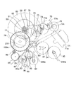
図1は、本発明の一実施形態に係る腕時計の外観構成を示す図である。図1に示すように、腕時計1は、時計本体部1aと、この時計本体部1aに連結されたベルト1bとを備えて構成されている。時計本体部1aは、筐体200と、この筐体200に設けられた円盤状の時刻表示盤202とを備え、この時刻表示盤202の上面には、秒針61と、分針(長針)62と、時針(短針)63からなる3つの表示指針が設けられている。時刻表示盤202には、その円周に沿って、時刻を示す記号が等間隔に配置されており、表示指針の各々が指し示す数字または記号(本実施形態では、記号には、文字も含まれるものとする)により、現在時刻が表示される。
FIG. 1 is a diagram showing an external configuration of a wristwatch according to an embodiment of the present invention. As shown in FIG. 1, the
また、時刻表示盤202には、略矩形にくり抜かれてなる日表示窓204と、24時表示部205と、月表示部206と、年表示部208とがそれぞれ設けられている。日表示窓204には、暦の「日」を示す「1」乃至「31」のいずれか1の数字が表示される。この場合、後述するように、1位の数字と10位の数字とは別々の日車(暦表示車)に付され、暦の「日」は、各日車に付された数字によって表示される。24時表示部205には、その円周に沿って、24等分された時刻を示す記号が等間隔に配置されており、表示指針205aが指し示す記号により「時間」が表示される。
The
また、月表示部206には、その円周に沿って、暦の「月」を示す、例えば「JAN」(1月を示す)〜「DEC」(12月を示す)のいずれか1の記号が等間隔に配置されており、表示指針206aが指し示す記号により暦の「月」が表示される。年表示部208には、その円周に沿って、数字「0」乃至「3」のいずれか1の数字が等間隔に表示され、閏年であれば、表示指針208aが数字「0」を指し示し、それ以降、「1」「2」「3」を指し示せば、それは閏年から何年目であるかを表示する。これにより、ユーザは暦の「年」を知ることができる。
In addition, the
この時計本体部1a内には、時刻表示盤202と略同形状の円盤状の地板303(図12)が配置され、この地板303を挟んで、時計の表側にはオートカレンダ機構(暦表示機構)が配置され、裏側には時計としての基本機構が配置されている。なお、この地板303は、オートカレンダ機構の各歯車の一端を軸支する部材として機能する。
A disc-shaped ground plate 303 (FIG. 12) having substantially the same shape as the
図2はオートカレンダ機構を示す図であり、図3はその拡大図である。このオートカレンダ機構は、上記地板303の一方の面(時計1の表側)に支持され、その駆動源は、圧電アクチュエータ(駆動手段)71である。この圧電アクチュエータ71は、振動子である圧電素子を備え、この圧電素子の振動により、圧電ロータ72の外周部を突っつき、これによって、当該圧電ロータ72を回転させる。この圧電ロータ72は圧電ロータかな72aを一体に備え、この圧電ロータかな72aには、中間車73が噛み合い、その中間車かな73aには、中間車74が噛み合う。この中間車74の中間車かな74aには、中間車75が噛み合い、その中間車かな75aには、中間車76が噛み合う。この中間車76は、制御車かな77に噛み合い、この制御車かな77は、制御車78と一体に形成される。ここまでは制御車78を回すための減速輪列である。なお、211は、制御車かな77の位置決め用のジャンパである。
FIG. 2 is a diagram showing an auto-calendar mechanism, and FIG. 3 is an enlarged view thereof. This auto-calendar mechanism is supported on one surface of the main plate 303 (the front side of the timepiece 1), and its drive source is a piezoelectric actuator (drive means) 71. The
制御車78は、爪数が異なる複数の爪車を備え、いずれかの爪車が、図2中、制御車78の上方に位置する、1位の日車(1位表示体(暦表示車))89を回す日回し車87と、10位の日車(10位表示体(暦表示車))92を回す日回し車90と、図中で制御車78の右下に位置する、月車(暦表示車)82を回す月表示中間車79とにそれぞれ噛み合う。ここで、1位の日車89の外周表面には「0」〜「9」の数字が周方向に等間隔に表示され、10位の日車92の外周表面には「空領域」と「1」〜「3」の数字が周方向に等間隔に表示される。なお、「空領域」とは数字の記載がない領域で、該当日が一桁の「日」(すなわち、1日〜9日)に相当するとき、10位に位置付けられる。
The
上述した日表示窓204には、1位の日車89上の数字「0」〜「9」と、10位の日車92上の「空領域」或いは数字「1」〜「3」との組み合わせにより、暦の「日」を示す「1」乃至「31」のいずれかの数字が表示される。
In the
上述した制御車78が回転すると、まず、1位の日車89に対応する歯車体の1位送り爪を介して、日回し車87および1位日かな88が回転し、これと一体に1位の日車89が回転し、その外周表面上の数字「0」〜「9」が、原則的に、1日に1回の割合で周方向に一つ送られる。この制御車78の回転に応じて、1位の日車89の回転が進み、10位が繰り上がる日付に至ると、今度は、10位の日車92に対応した歯車体の10位送り爪を介して、日回し車90および10位日かな91が回転し、これと一体に10位の日車92が回転し、その外周表面上の「空領域」或いは数字「1」〜「3」が、10日に1回の割合で周方向に一つ送られる。
When the above-described
また、制御車78の回転に対応して、1位の日車89および10位の日車92の回転が進み、「月」の表示が繰り上がる日付に至ると、今度は、月車82に対応した歯車体の月送り爪を介して、月表示中間車79および月検出車80が回転し、これと一体に月車82が回転する。そして、その表示指針206aが回転し、月表示部206上の暦の「月」を示す「JAN」(1月を示す)〜「DEC」(12月を示す)のいずれか1の記号が指し示され、暦の「月」表示が行われる。ここまでが月車82を回すための減速輪列である。
In response to the rotation of the
上記月検出車80には、年表示中間車83が噛み合い、この年表示中間車83には年送り車84が噛み合う。そして、この年送り車84には年車(暦表示車)85が噛み合い、この年車85には、暦の「年」を指し示す表示指針208aが接続される。この場合、年送り車84は、1年の期間を経て、初めて年車85を90°回転させるように構成される。従って、表示指針208aは、1年に1回送られる。そして、閏年であれば、表示指針208aが数字「0」を指し示し、それ以降、「1」「2」「3」を指し示せば、例えば、それは閏年から何年目であるかを表示し、これにより、暦の「年」が表示される。
The
上記24時表示部205では、その駆動力が、オートカレンダ機構の駆動源とは異なり、地板303の裏側に配置された時計の後述する運針機構E(図13)の駆動源から取られる。すなわち、運針機構Eの筒車(時針(短針)63を支持する筒車)に筒車体93が一体化されており、この筒車体93には、24時検出車94が噛み合う。そして、この24時検出車94には、24時車95が噛み合い、この24時車95の回転により、24時表示部205の表示指針205aが回転する。この表示指針205aは、1時間に1回送られる。
In the 24-
次に、カレンダ検出(月検出、年検出および日検出)について説明する。
上記構成において、月検出車80には、表示される月が、2月か、2月を除く「小」の月(ひと月の日数が31日に満たない2月、4月、6月、9月、11月)か、「大」の月かの3パターンを検出するためのばねスイッチ330が設けられる。このばねスイッチ330は、月検出車80の回転位置に応じて開閉される機械式スイッチであり、図2および図4に示すように、月検出車80の支持軸81に固定されたばね接点98と、地板303に配置された回路基板303aの配線パターンの一部を構成する複数のスイッチ端子98Tとから構成される。ここで、図5はばね接点98の平面図であり、図6はスイッチ端子98Tの配置を示す図である。
Next, calendar detection (month detection, year detection, and day detection) will be described.
In the above configuration, the
図5に示すように、ばね接点98は、弾性を有する金属材料、例えば、リン青銅やステンレス鋼等で形成され、略中央に月検出車80の支持軸81に挿通される孔99を有し、外側に延びる3本の足部98a、98b、98cを一体的に備える3本足構成に形成される。これら足部98a〜98cは同一長さに形成されると共に、先端部に円形状の窪み98dが設けられ、この窪み98dがスイッチ端子98Tと点接触することでスイッチ端子98Tとの摩擦抵抗を小さくしている。本実施形態では、この3本の足部98a〜98cを150度、60度、150度の間隔で配置し、図5に示す一点鎖線を基準に左右対称形状に形成されている。このように左右対称形状に形成することで、重心位置を中央にして回転バランスを良好にでき、月検出車80の回転に悪影響を与えないようにすると共に、スイッチ端子98Tとの接触圧の偏りをなくして負荷トルクの偏りを回避するようになされている。
As shown in FIG. 5, the
図6に示すように、スイッチ端子98Tには、電源端子98T1と、2月検出用の第1検出端子98T2と、小の月検出用の第2検出端子98T3とがあり、これら端子98T1〜98T3は月検出車80の軸81を中心とする同一円周上に配置される。ここで、図6においては、表示される月が1月の時のばね接点98の位置を簡略的に示しており、このばね接点98の回転方向(=月検出車80の回転方向)を符号αで示している。
As shown in FIG. 6, the
本実施形態の構成、つまり、月検出車80(ばね接点98)がひと月当たり30度回転する構成では、図示のように、第1検出用端子98T2を基準(0度の位置)とすると、電源端子98T1は、60°、180°、330°の位置にそれぞれ配置され、第2検出端子98T3は、120°、210°、270°の位置にそれぞれ配置される。すなわち、スイッチ端子98Tは、同一円周上に7個配置される。そして、この電源端子98T1には後述する電源部C(図13)の電力(VDDライン)が供給され、第1検出用端子98T2は後述する制御部A(図13)の端子CS0と接続され、第2検出端子98T3は制御部Aの端子CS1と接続されるようになっている。
In the configuration of the present embodiment, that is, in the configuration in which the month detection wheel 80 (spring contact 98) rotates 30 degrees per month, the first detection terminal 98T2 is used as a reference (0-degree position) as shown in the figure. The terminal 98T1 is disposed at positions of 60 °, 180 °, and 330 °, and the second detection terminal 98T3 is disposed at positions of 120 °, 210 °, and 270 °, respectively. That is, seven
これにより、図7に表示される月毎の端子CS0および端子CS1の状態を示すように、表示される月が2月の場合に、ばね接点98が電源端子98T1と第1検出用端子98T2とに接触して端子CS0に電力(VDD)が供給され、また、表示される月が小の月の場合に、ばね接点98が電源端子98T1と第2検出端子98T3とに接触して端子CS1に電力(VDD)が供給されることとなる。制御部Aは、この端子CS0および端子CS1の状態(HレベルかLレベル)の組み合わせを検出することにより、図8に示す月情報検出パターン(2ビット化したパターン)に基づいて、表示されている「月」が、「2月」か、2月を除く「小の月」か、或いは「大の月」かのいずれかを検出できるようになっている。
Thus, as shown in the states of the monthly terminals CS0 and CS1 displayed in FIG. 7, when the displayed month is February, the
このように、このばねスイッチ300は、大の月の場合は、ばね接点98が電源端子98T1を含むスイッチ端子98Tと接触しない構成となっているため、係る場合に負荷トルクが生じる場合が回避されている。また、スイッチ端子98Tは同一円周上に配置されるため、月検出車80が小径でばねスイッチの配置可能エリア(月検出車80の直径が4.7mmの場合は直径3.0mmの範囲)が小さくてもそのエリア内に配置することが可能となっている。
As described above, the
また、上記構成において、年表示中間車83の中間車かな83aには、年検出車86が噛み合い、この年検出車(検出車)86には上記ばねスイッチ330と略同様のばねスイッチ320が設けられる。具体的には、図2および図4に示すように、年検出車86の支持軸にばね接点96が設けられ、このばね接点96と対向する回路基板上には、年検出車86の回転に応じて、年検出車86と共に回転するばね接点96を介して導通するスイッチ端子96Tが設けられる。
In the above configuration, the
ここで、図9は、スイッチ端子96Tの配置を示す図である。この図に示すように、このスイッチ端子96Tは、表示される年が「閏年」の際に、ばね接点96を介して導通する電源端子96T1と閏年検出用端子96T2とである。制御部Aは、この閏年検出用端子96T2と接続された端子CS2を介してばねスイッチ320の開閉(HレベルかLレベルか)を検出することにより、図10に示す年情報検出パターンに基づいて該当年が「閏年」か「非閏年(平年)」かの2パターンを検出するようになっている。このばねスイッチ320においても、「非閏年」の場合は、ばね接点96が電源端子96T1および閏年検出用端子96T2と接触しないため、係る場合に負荷トルクが生じる場合が回避されている。なお、このばね接点96は、上記ばね接点98と同一のものが使用され、これにより部品の共有化が図られている。
Here, FIG. 9 is a diagram showing the arrangement of the
また、1位の日車(検出車)89および10位の日車(検出車)92の裏面には、反射領域と非反射領域とが設けられた光検出用パターン(図示せず)が設けられ、地板303に設けられた基板上に、このパターンを読みとる複数のフォトリフレクタ(反射型フォトセンサ)が設けられる。具体的には、10位の日車92と対向する基板上には、異なる位置に光を照射してその反射光を受光する2つのフォトリフレクタが配置され、この日車92の裏面には、各フォトリフレクタによって、表示されている日が、「00or10」、「20」、「30」のいずれかを判別可能にする光検出用パターンが設けられる。この2つのフォトリフレクタの一方は、制御部Aの端子PT2に接続され、他方は端子PT3に接続される。また、1位の日車89と対向する基板上にも、2つのフォトリフレクタが配置され、この日車89の裏面には、各フォトリフレクタによって、表示されている1位の「日」が「2〜8」、「9」、「0」、「1」のいずれかを判別可能にする光検出用パターンが設けられる。この2つのフォトリフレクタの一方は、制御部Aの端子PT0に接続され、他方は端子PT1に接続される。
A light detection pattern (not shown) provided with a reflective region and a non-reflective region is provided on the back surface of the first date wheel (detection wheel) 89 and the 10th date wheel (detection wheel) 92. A plurality of photo reflectors (reflection photosensors) that read this pattern are provided on a substrate provided on the
図11に日情報検出パターンを示すように、制御部Aは、これら4つのフォトリフレクタの受光結果に基づいて、表示されている10位の「日」が、「0or1」か、「2」か、「3」のいずれかを検出すると共に、表示されている1位の「日」が、小の月には存在しない日(29、30、31)の1位の日である「9」か、「0」か、「1」か、それとも「2〜8」のいずれかを検出するようになっている。すなわち、日の検出パターン数は12となっている。但し、この検出パターンには、非存在の日(0日、32〜38日、39日)を含んでおり、また、日検出は、後述するように存在日か否か(月末補正が必要か否か)を判定するために使用されるものであるから、最低、「1〜28日」、「29日」、「30日」、「31日」の4種類の検出パターンを検出すればよい。 As shown in the day information detection pattern in FIG. 11, the control unit A determines whether the displayed 10th “day” is “0or1” or “2” based on the light reception results of these four photo reflectors. , “3” is detected, and the displayed first “day” is “9”, which is the first day of the days (29, 30, 31) that do not exist in the small month. , “0”, “1”, or “2-8”. That is, the number of detection patterns for the day is 12. However, this detection pattern includes a non-existing day (0 day, 32-38 day, 39 day), and whether the day detection is an existing day as described later (whether month-end correction is necessary). It is only necessary to detect four types of detection patterns of “1 to 28 days”, “29 days”, “30 days”, and “31 days”. .
上述したように、本実施形態では、検出パターン数が多く、かつ、圧電ロータ72に対する減速比が小さい歯車、すなわち、回転トルクが小さい歯車(日車89、92)を用いる日検出には、非接触検知のため比較的耐久性が高いフォトリフレクタを用い、その他のカレンダ検出には、上記ばねスイッチを用いることで、耐久性にも負荷トルク低減にも消費電力低減にも優れたカレンダ検出機構が提供される。
As described above, in the present embodiment, the date detection using a gear having a large number of detection patterns and a small reduction ratio with respect to the
次に、圧電ロータ72の送り量検出および24時検出について説明する。
圧電ロータ72の送り量検出は、上述した中間車75に設けた、上記ばねスイッチ330と略同様のばねスイッチ300で行うようになっている。具体的には、図12に示すように、中間車75の支持軸にばね接点301が設けられ、このばね接点301と対向する回路基板上には、中間車75の回転位置に応じてばね接点96を介して導通するスイッチ端子302が設けられる。このスイッチ端子302は、圧電ロータ72の送り量が暦を1日分送る送り量になる毎に、つまり、その送り量に対応する角度だけ中間車75が回転する毎に、ばね接点301を介して導通した状態(閉状態)から非導通の状態(開状態)に切り替わるように、回路基板303aの配線パターンの一部として構成されている。このスイッチ端子302は、制御部Aと接続され、制御部Aは、このばねスイッチ300の開状態から閉状態への切り替わりを検出することにより、圧電ロータ72の送り量が暦を1日分送る送り量となったことを検出する。すなわち、このばねスイッチ300は、圧電ロータ72の送り量を検出するロータ送り量検出手段として機能する。
Next, feed amount detection and 24:00 detection of the
The feed amount of the
また、24時検出車94には、上記ばねスイッチ330と略同様のばねスイッチ310が設けられ、このばねスイッチ310により、表示指針205aが「午前零時」を指し示したことが検出される。具体的には、図2に示すように、24時検出車94には、ばね接点97が設けられ、このばね接点97と対向する回路基板上に、24時検出車94が「午前零時」の回転位置となったときにばね接点97を介して導通するスイッチ端子(図示せず)が設けられる。このばねスイッチ310の開閉は、後述する制御部Aによって検出される。すなわち、このばねスイッチ310は、「午前零時」を検出する24時検出手段として機能する。このばねスイッチ310においても、「午前零時」以外の場合は、ばね接点97がスイッチ端子(電源端子を含む)と接触せず、「午前零時」以外では負荷トルクが生じないように構成されている。なお、ばね接点301および97についても、ばねスイッチ330のばね接点98と同一のものが使用され、部品の共有化が図られている。
The 24-
図13は、腕時計1の電気的構成を機械的構成と共に示す図である。同図に示すように、腕時計1は、制御部Aと、発電部Bと、電源部Cと、指針駆動部Dと、運針機構Eと、日付機構駆動部Fと、オートカレンダ機構(圧電ロータ72のみを示す)とを備えている。
FIG. 13 is a diagram showing an electrical configuration of the
発電部Bは、交流電力を発電するものであり、回転錘45を備えている。この回転錘45は、ユーザの手首などの動きに伴って旋回可能に設けられており、回転錘45の旋回(運動エネルギー)が増速用ギア46を介して発電装置40に伝達されるようになっている。発電装置40は、発電用ステータ42と、この発電用ステータ42の内部に回転可能に設けられた発電用ロータ43と、発電用ステータ42に電気的に接続された発電コイル44とを備えており、発電用ロータ43が回転錘45の旋回(運動エネルギー)により回転し、この回転により発電コイル44に交流電圧が誘起されるようになっている。つまり、腕時計1がユーザに装着されている間、ユーザが何らかの動作をするに伴い、回転錘45が旋回することにより、発電が行われる。
The power generation unit B generates AC power and includes a rotating
電源部Cは、発電部Bからの交流電圧を整流して蓄電し、蓄電した電力を昇圧して各構成部分へ給電する。具体的に説明すると、電源部Cは、整流回路として作用するダイオード47、大容量コンデンサ48および昇降圧回路49から構成されている。昇降圧回路49は、3つの容量49a、49bおよび49cを用いて多段階の昇圧および降圧ができるようになっており、制御部Aからの制御信号によって指針駆動部Dに供給する電圧を調整することができる。また、昇降圧回路49の出力電圧はモニタ信号によって制御部Aにも供給されており、これによって、制御部Aは、出力電圧をモニタしている。ここで、電源部Cは、Vdd(高電圧側)を基準電位(GND)に取り、Vss(低電圧側)を電源電圧として生成している。
The power supply unit C rectifies and stores the AC voltage from the power generation unit B, boosts the stored power, and supplies power to each component. More specifically, the power supply unit C includes a
指針駆動部Dは、制御部Aの制御の下、運針機構Eに様々な駆動パルスを供給するものである。本実施形態では、指針駆動部Dは、秒針61を駆動する秒針駆動部D1と、時針63、分針62および24時表示用の表示指針205aを駆動する時分針駆動部D2とから構成されている。さらに説明すると、秒針駆動部D1は、直列に接続されたpチャンネルMOS33aとnチャンネルMOS32a、およびpチャンネルMOS33bとnチャンネルMOS32bによって構成されたブリッジ回路を備えている。また、秒針駆動部D1は、pチャンネルMOS33aおよび33bとそれぞれ並列に接続された回転検出用抵抗35aおよび35bと、これらの抵抗35aおよび35bにチョッパパルスを供給するためのサンプリング用のpチャンネルMOS34aおよび34bを備えている。したがって、これらのMOS32a、32b、33a、33b、34aおよび34bの各ゲート電極に制御部Aからそれぞれのタイミングで極性およびパルス幅の異なる制御パルスが印加されることにより、運針機構Eの一部を構成する秒針運針機構E1に、例えば極性の異なる駆動パルスなどの様々の駆動パルスを供給することができるようになっている。
The pointer drive unit D supplies various drive pulses to the hand movement mechanism E under the control of the control unit A. In the present embodiment, the pointer drive unit D includes a second hand drive unit D1 that drives the
また、時分針駆動部D2は、秒針駆動部D1と略同様に構成され、制御部Aから極性およびパルス幅の異なる制御パルスが印加されることにより、運針機構Eの一部を構成する時分針運針機構E2に、例えば極性の異なる駆動パルスなどの様々の駆動パルスを供給することができるようになっている。 The hour / minute hand driving unit D2 is configured in substantially the same manner as the second hand driving unit D1, and a control pulse having a polarity and a pulse width different from the control unit A is applied to form the hour / minute hand constituting a part of the hand movement mechanism E. Various drive pulses such as drive pulses having different polarities can be supplied to the hand movement mechanism E2.
運針機構Eは、秒針運針機構E1と時分針駆動部E2から構成される。秒針運針機構E1は、ステッピングモータ10を備え、このステッピングモータ10により秒針61を回転駆動する。詳述すると、ステッピングモータ10は、秒針駆動部D1から供給される駆動パルスによって磁力を発生する駆動コイル11と、この駆動コイル11によって励磁されるステータ12と、さらに、ステータ12の内部において励磁される磁界により回転するロータ13を備えている。また、ステッピングモータ10は、ロータ13がディスク状の2極の永久磁石によって構成されたPM型(永久磁石回転型)で構成されている。ステータ12には、駆動コイル11で発生した磁力によって異なった磁極がロータ13の回りのそれぞれの相(極)15および16に発生するように磁気飽和部17が設けられている。また、ロータ13の回転方向を規定するために、ステータ12の内周の適当な位置には内ノッチ18が設けられており、コギングトルクを発生させてロータ13が適当な位置に停止するようにしている。このステッピングモータ10のロータ13の回転は、かなを介してロータ13に噛合された秒中間車51および秒車52からなる輪列50によって秒針61に伝達され、秒針61が回転駆動される。
The hand movement mechanism E includes a second hand movement mechanism E1 and an hour / minute hand drive unit E2. The second hand moving mechanism E <b> 1 includes a stepping
また、時分針駆動部E2は、ステッピングモータ20を備えており、ステッピングモータ20が分針62を回転駆動することにより、この分針62の回転に連動して、時針63と24時表示用の表示指針205aとを回転駆動する。詳述すると、ステッピングモータ20は、上記ステッピングモータ10と同様に、ステータ22とロータ23を備え、ステータ22には、駆動コイル21で発生した磁力によって異なった磁極がロータ23の周りのそれぞれの相(極)25および26に発生するように磁気飽和部27Aが設けられている。また、ロータ23の回転方向を規定するために、ステータ22の内周の適当な位置には内ノッチ28Aが設けられ、コギングトルクを発生させてロータ23が適当な位置に停止するようになっている。
The hour / minute hand drive unit E2 includes a stepping
このステッピングモータ20のロータ23の回転は、かなを介してロータ23に噛合された四番車26、三番車27、二番車28、日の裏車29、筒車(時指示車)93a、筒車体93、24時検出車94および24時車95からなる輪列30によって各針に伝達される。二番車29には分針62が接続され、筒車93aには時針63が接続され、さらに、24時車95には表示指針205aが接続されている。ロータ23の回転に連動してこれらの各針によって時分が表示される。
The rotation of the rotor 23 of the stepping
日付機構駆動部Fは、制御部Aの制御の下、圧電アクチュエータ71の圧電素子に交流電圧を印加することにより、圧電アクチュエータ71に振動を生じさせ、この振動により圧電ロータ72の外周部を突っついて当該圧電ロータ72を回転駆動させ、これによって、オートカレンダ機構を駆動するものである。ここで、日付機構駆動部Fは、地板を介して運針機構Eとは対向して配置されることが望ましい。
Under the control of the control unit A, the date mechanism driving unit F applies an AC voltage to the piezoelectric element of the
図14は、制御部Aの機能構成を示すブロック図である。制御部Aは、腕時計1の各部を制御するものであり、指針駆動部Dおよび運針機構Eを制御する時計制御部A1と、オートカレンダ機構を制御してカレンダ送り処理を行うカレンダ制御部A2とを備えている。カレンダ制御部A2は、上述したばねスイッチ300、310、320、321、332およびフォトリフレクタ(図中PRで示す)と電気的に接続されており、24時検出車94に設けられたばねスイッチ300が閉状態となった場合に、カレンダ送り処理として、オートカレンダ機構を1日分だけ回転駆動する1日送り処理と、送られた日を検出して非存在日であるか否かを判定するカレンダ検出処理と、非存在日であると判断すると、実際の存在日を表示させるべくオートカレンダ機構を駆動していわゆる月末補正を行うカレンダ補正処理とを実行する。
FIG. 14 is a block diagram illustrating a functional configuration of the control unit A. As illustrated in FIG. The control unit A controls each part of the
図15は、カレンダ送り処理を示すフローチャートである。また、図16は、このカレンダ送り処理時の1日送り処理のときのタイミングチャートを示す図である。まず、カレンダ制御部A2は、時刻が「午前零時」になり、図16に示すように、24時検出車94に設けられたばねスイッチ310が閉じてこのばねスイッチ310に接続された端子がHレベルに切り替わったことを検出すると、(ステップS1)、日付機構駆動部Fに対して日送信号(スタート信号)を出力する。この場合、日付機構駆動部Fが圧電アクチュエータ71駆動用の交流信号を出力することにより、圧電ロータ72が回転駆動されてオートカレンダ機構が駆動される(ステップS2)。そして、圧電ロータ72の送り量が1日分の送り量となり、圧電ロータ72の送り量検出用のばねスイッチ300が開から閉に切り替わり、このばねスイッチ300に接続された端子がHレベルからLレベルに切り替わったことを検出すると、日付機構駆動部Fに対してストップ信号を出力してオートカレンダ機構の駆動を停止させる(ステップS3)。以上が1日送り処理である。このように、圧電アクチュエータ71の駆動時にばねスイッチ300で圧電ロータ72の送り量を検出するように構成しているので、比較的消費電力が多いフォトリフレクタで圧電ロータ72の送り量を検出する場合に比して、圧電アクチュエータ71の駆動と、圧電ロータ72の送り量検出とを同時に行う場合の消費電力を低くすることが可能となっている。
FIG. 15 is a flowchart showing the calendar feeding process. FIG. 16 is a diagram showing a timing chart for the 1-day feed process during the calendar feed process. First, the calendar control unit A2 makes the time “midnight”, and as shown in FIG. 16, the
続いて、カレンダ制御部A2は、カレンダ検出処理を実行する。具体的には、カレンダ制御部A2は、まず、端子CS1の検出を行い(ステップS4)、検出した電位(HレベルかLレベル)に基づいて、現在表示されている月が「大の月」か否かを判定する(ステップS5)。具体的には、図8に示すように、カレンダ制御部A2は、端子CS1はLレベルであれば「大の月」と判定する。「大の月」と判定すると、「大の月」は非存在日が存在しない月であるため、存在日を表示していると判定でき、カレンダ制御部A2は、カレンダ送りの処理を終了する。 Subsequently, the calendar control unit A2 executes a calendar detection process. Specifically, the calendar control unit A2 first detects the terminal CS1 (step S4), and the currently displayed month is “large month” based on the detected potential (H level or L level). Is determined (step S5). Specifically, as shown in FIG. 8, the calendar control unit A2 determines “large moon” if the terminal CS1 is at the L level. If it is determined as “large month”, since the “large month” is a month with no non-existing date, it can be determined that the existing date is displayed, and the calendar control unit A2 ends the calendar feeding process. .
ステップS5において、現在表示されている月が「大の月」でない(すなわち月末補正を必要とする設定暦情報に該当する(端子CS1がHレベル))と判定すると、カレンダ制御部A2は、端子PT3に対応するフォトリフレクタを駆動し、このフォトリフレクタの検出結果を端子PT3を介して検出する(ステップS6)。そして、カレンダ制御部A2は、検出した電位に基づいて、現在表示されている「日」が「1〜19日」に該当するか否かを判定する(ステップS7)。具体的には、図11に示すように、カレンダ制御部A2は、端子PT3がLレベルであれば、「日」の10位の値が「0」か「1」であるため、表示されている「日」が「1〜19日」と判定する。「1〜19日」と判定した場合は、月末補正が不必要な日、つまり、存在日を表示していると判定できるため、カレンダ制御部A2は、カレンダ送りの処理を終了する。 If it is determined in step S5 that the currently displayed month is not the “large month” (that is, it corresponds to the set calendar information that requires month end correction (the terminal CS1 is at the H level)), the calendar control unit A2 The photo reflector corresponding to PT3 is driven, and the detection result of the photo reflector is detected via the terminal PT3 (step S6). Then, the calendar control unit A2 determines whether the currently displayed “day” corresponds to “1 to 19 days” based on the detected potential (step S7). Specifically, as shown in FIG. 11, if the terminal PT3 is at the L level, the calendar control unit A2 is displayed because the tenth value of “day” is “0” or “1”. It is determined that the “day” is “1 to 19 days”. When it is determined as “1 to 19 days”, it can be determined that the day when month-end correction is unnecessary, that is, the existence date is displayed, and thus the calendar control unit A2 ends the calendar feeding process.
ステップS7において、現在表示されている「日」が「1〜19日」でない(すなわち月末補正を必要とする設定暦情報に該当する(端子PT3がHレベル))と判定すると、カレンダ制御部A2は、端子PT0〜PT2に対応するフォトリフレクタを駆動し、これらフォトリフレクタの検出結果を端子PT0〜PT2を介して検出する(ステップS8)。なお、これらフォトリフレクタはタイミングをずらして駆動することが好ましい。このように複数のフォトリフレクタの駆動タイミングをずらすことによって、駆動電源の定格電流を超えてしまう場合を容易に回避することができる。そして、カレンダ制御部A2は、端子PT0〜PT2の検出結果の組み合わせから現在表示されている日が、「20〜28日」に該当するか否かを判定する(ステップS9)。具体的には、カレンダ制御部A2は、図11に示すように、端子PT2がLレベルで、かつ、端子PT1がHレベル或いは端子PT0がLレベルの場合に「20〜28日」であると判定する。「20〜28日」と判定した場合は、大の月と小の月の両方に必ず存在する日であるため、存在日と判定でき、カレンダ制御部A2は、カレンダ送りの処理を終了する。 If it is determined in step S7 that the currently displayed "day" is not "1-19 days" (that is, it corresponds to the set calendar information that requires month end correction (terminal PT3 is at H level)), calendar control unit A2 Drives the photo reflectors corresponding to the terminals PT0 to PT2, and detects the detection results of these photo reflectors via the terminals PT0 to PT2 (step S8). These photo reflectors are preferably driven at different timings. By shifting the drive timing of the plurality of photo reflectors in this way, it is possible to easily avoid the case where the rated current of the drive power source is exceeded. Then, the calendar control unit A2 determines whether or not the currently displayed day corresponds to “20 to 28 days” from the combination of the detection results of the terminals PT0 to PT2 (step S9). Specifically, as shown in FIG. 11, the calendar control unit A2 is “20 to 28 days” when the terminal PT2 is at the L level and the terminal PT1 is at the H level or the terminal PT0 is at the L level. judge. When it is determined as “20 to 28 days”, since it is a day that always exists in both the large month and the small month, it can be determined to be an existing day, and the calendar control unit A2 ends the calendar feeding process.
すなわち、カレンダ制御部A2は、まず、現在表示されている月が「大の月」か否かを判定し、「大の月」でない場合にのみ日の検出を行う。従って、現在表示されている月が「大の月」の場合は、日や年の検出を行わないので、その分、カレンダ検出に要する電力を節約することが可能となる。また、「大の月」でない場合、カレンダ制御部A2は、一つのフォトリフレクタだけを駆動してその検出結果から現在表示されている日が「1〜19日」か否かを判定し、つまり、日の10位が小の月と大の月に必ず存在する「1」か「0」に該当するか否かを判定し、該当しない場合にのみ他のフォトリフレクタを駆動して日の1位の検出を行う。従って、日の1位が「1」か「0」の場合は日の10位の検出を行う必要がないので、その分、カレンダ検出に要する電力を節約することができる。 That is, the calendar control unit A2 first determines whether or not the currently displayed month is a “large month”, and performs day detection only when it is not a “large month”. Accordingly, when the currently displayed month is the “large month”, the day and year are not detected, and accordingly, it is possible to save the power required for calendar detection. If it is not “large month”, the calendar control unit A2 drives only one photo reflector and determines whether or not the currently displayed day is “1 to 19 days” from the detection result. , It is determined whether or not the 10th place of the day corresponds to “1” or “0” that always exists in the small month and the large month, and if not, only the other photo reflector is driven to The position is detected. Therefore, when the 1st place of the day is “1” or “0”, it is not necessary to detect the 10th place of the day, so that the power required for calendar detection can be saved accordingly.
また、ステップS9において、現在表示されている日が「20〜28日」ではない(すなわち月末補正を必要とする設定暦情報に該当する)と判定すると、カレンダ制御部A2は、端子CS0と端子CS2の検出を行い(ステップS10)、現在表示されている、年、月および日を全て検出する。以上がカレンダ検出処理であり、次にカレンダ補正処理を説明する。 If it is determined in step S9 that the currently displayed date is not “20 to 28 days” (that is, it corresponds to the set calendar information that requires month-end correction), calendar control unit A2 determines that terminal CS0 and terminal CS2 is detected (step S10), and all the year, month and day currently displayed are detected. The above is the calendar detection process. Next, the calendar correction process will be described.
まず、カレンダ制御部A2は、検出した年月日に基づいて現在表示されている日が「31日」か否か、具体的には、図11に示すように、端子PT1と端子PT0とがHレベルか否かを判定する(ステップS11)。「31日」と判定した場合、カレンダ制御部A2は、現在表示されている月が「2月を除く小の月」か否か、具体的には、端子CS1と端子CS0とがHレベルか否かを判定し(ステップS12)、「2月を除く小の月」と判定すると、非存在日が表示されていると判定できるため、存在日が表示されるように、日付機構駆動部Fに対して日送信号を出力してオートカレンダ機構を1日分回転駆動させ(ステップS13)、このカレンダ送り処理を終了する。 First, the calendar control unit A2 determines whether or not the currently displayed day is “31st” based on the detected date, specifically, as shown in FIG. It is determined whether or not it is at the H level (step S11). When it is determined as “31st”, the calendar control unit A2 determines whether the currently displayed month is “small month except February”, specifically, whether the terminal CS1 and the terminal CS0 are at the H level. If it is determined whether or not (step S12) and “small month excluding February” is determined, it can be determined that the non-existing date is displayed, so that the date mechanism driving unit F is displayed so that the existing date is displayed. In response to this, a date signal is output to rotate the auto-calendar mechanism for one day (step S13), and this calendar feeding process is terminated.
ところで、この腕時計1においては、発電部Bが所定期間(例えば3日間)継続して発電していない場合に、通常の動作モードから、運針機構Eとオートカレンダ機構の駆動を停止して節電を図る節電モードに切り換え、発電部Bの発電が検出されると、内部の時計回路で計測していた現在時刻を表示するまで運針機構Eを高速駆動すると共に、その節電モードの経過日数分だけ日付を進めるべく、オートカレンダ機構を回転駆動させて時刻およびカレンダを現在のものに復帰させる機能を具備している。この復帰の際、節電モードの期間が例えば2年以下の場合は通常のカレンダ送りと同回転方向の正回転でオートカレンダ機構を駆動する一方、例えば、2年以上4年以下の場合は逆回転でオートカレンダ機構を駆動し、これにより、オートカレンダ機構の回転駆動量が少ない回転方向に回転駆動させて高速復帰と低消費電力との両立を図るようになっている。しかしながら、このオートカレンダ機構の復帰は、月末修正を考慮せずに、単に節電モードの経過日数分だけ日付を進めるものであるため、「2月31日」、「2月30日」、および平年の「2月29日」を表示してしまう場合が生じる。本実施形態ではかかる復帰動作を行った場合にもステップS4移行の処理が実施され、この場合も考慮してカレンダ補正処理が規定されている。なお、節電モードの期間が2年以上4年以下の場合に、通常のカレンダ送りと同回転方向の正回転でオートカレンダ機構を駆動しても差し支えない。
By the way, in this
また、本発明では節電モード時はカレンダ送りも停止し、時刻復帰時に合わせカレンダ復帰をする説明を行ったが、節電モード時は時刻送りを停止させ、カレンダ送りのみ1日毎に実施してもよい。この場合、最初の24時検出を電気接点により検出後は24時間のカウンタをIC上で持たせ、節電モードのみこのカウンタにより24時間毎にカレンダ送りを実施してステップS4以降の処理を実施すればよく、長時間放置後の節電モード復帰時にカレンダ送りにかかる長い復帰時間の回避や復帰時間中の操作制限を回避することができる。 In the present invention, the calendar feeding is also stopped in the power saving mode, and the calendar is reset when the time is restored. However, in the power saving mode, the time feeding is stopped and only the calendar feeding may be performed every day. . In this case, after the first 24 o'clock detection is detected by the electrical contact, a 24-hour counter is provided on the IC, and only in the power saving mode, calendar feeding is performed every 24 hours by this counter, and the processing after step S4 is performed. In other words, it is possible to avoid a long recovery time required for calendar feeding when returning to the power saving mode after being left for a long time, and to avoid an operation limitation during the recovery time.
具体的には、ステップS12の処理において、「2月を除く小の月」ではない、つまり、「2月31日」を表示していると判定すると、カレンダ制御部A2は、オートカレンダ機構の復帰時の回転方向が正転(正回転)だったか否かを判定し(ステップS14)、正転の場合はステップS13に移行し、オートカレンダ機構を1日分回転駆動させて「3月1日」を表示させた後、このカレンダ送り処理を終了する。一方、正転でないと判定すると、カレンダ制御部A2は、端子CS2の検出結果に基づいて閏年か否かを判定し(ステップS15)、閏年の場合は、オートカレンダ機構を2日分逆転駆動させて「2月29日を表示させ(ステップS16)、閏年でない場合は、オートカレンダ機構を3日分逆転駆動させて「2月28日」を表示させた後(ステップS17)、カレンダ送り処理を終了する。これにより、正転又は逆転により「2月31日」が表示された場合も適切に存在日に補正することが可能となっている。なお、上記節電モードの機能を具備しない腕時計にあっては、ステップS15〜S17の処理を省略すればよい。 Specifically, in the process of step S12, when it is determined that it is not “small month except February”, that is, “February 31” is displayed, the calendar control unit A2 determines the auto-calendar mechanism. It is determined whether or not the rotation direction at the time of return is normal rotation (normal rotation) (step S14). If the rotation direction is normal rotation, the process proceeds to step S13, and the auto-calendar mechanism is rotationally driven for one day to “March 1”. After displaying “day”, the calendar feeding process is terminated. On the other hand, when it is determined that the rotation is not normal, the calendar control unit A2 determines whether or not it is leap year based on the detection result of the terminal CS2 (step S15), and in the case of leap year, the auto-calendar mechanism is driven in reverse for two days. “February 29 is displayed (step S16). If it is not a leap year, the auto-calendar mechanism is driven in reverse for three days to display“ February 28 ”(step S17), and then the calendar feeding process is performed. finish. Thus, even when “February 31” is displayed by normal rotation or reverse rotation, it is possible to appropriately correct the existing date. Note that in a wristwatch that does not have the power saving mode function, the processes in steps S15 to S17 may be omitted.
また、ステップS11において、「31日」でないと判定した場合、カレンダ制御部A2は、「2月を除く小の月」の「30日」か否か、具体的には、端子CS0がLレベルで、端子PT2がHレベルであったか否かを判定する(ステップS20)。「2月を除く小の月」の「30日」と判定すると、カレンダ制御部A2は、存在日を表示していると判定できるため、カレンダ送りの処理を終了する。 If it is determined in step S11 that it is not “31st”, the calendar control unit A2 determines whether it is “30th” of “small month except February”, specifically, the terminal CS0 is at the L level. Then, it is determined whether or not the terminal PT2 is at the H level (step S20). If it is determined that “30 days” of “small month excluding February”, the calendar control unit A2 can determine that the existing date is displayed, and thus the calendar sending process ends.
このステップS20において、「2月を除く小の月」の「30日」でないと判定すると、カレンダ制御部A2は、「2月30日」か否か、具体的には、端子CS0がHレベルで、端子PT2がHレベルであったか否かを判定する(ステップS21)。「2月30日」と判定すると、カレンダ制御部A2は、オートカレンダ機構の復帰時の回転方向が正転(正回転)だったか否かを判定し(ステップS22)、正転の場合は、オートカレンダ機構を2日分回転駆動させて「3月1日」を表示させた後(ステップS23)、このカレンダ送り処理を終了する。 If it is determined in step S20 that it is not “30th” of “small month except February”, the calendar control unit A2 determines whether it is “February 30”, specifically, the terminal CS0 is at the H level. Then, it is determined whether or not the terminal PT2 is at the H level (step S21). If it is determined as “February 30”, the calendar control unit A2 determines whether or not the rotation direction at the time of return of the auto-calendar mechanism is normal rotation (normal rotation) (step S22). The auto-calendar mechanism is rotated for two days to display “March 1” (step S23), and then the calendar feeding process is terminated.
また、正転でない(逆転)と判定すると、カレンダ制御部A2は、端子CS2の検出結果に基づいて閏年か否かを判定し(ステップS24)、閏年でない場合は、ステップS23に移行し、オートカレンダ機構を2日分逆転駆動させて「2月28日」を表示させ、閏年の場合は、オートカレンダ機構を1日分逆転駆動させて「2月29日」を表示させた後(ステップS25)、カレンダ送り処理を終了する。これにより、正回転又は逆回転で「2月30日」が表示された場合も適切に存在日に補正することが可能となっている。なお、上記節電モードの機能を具備しない腕時計にあっては、ステップS20〜S25の処理を省略することができる。 If it is determined that the rotation is not normal (reverse rotation), the calendar control unit A2 determines whether it is a leap year based on the detection result of the terminal CS2 (step S24). If it is not a leap year, the process proceeds to step S23. The calendar mechanism is reversely driven for two days to display “February 28”. In the case of leap years, the auto-calendar mechanism is reversely driven for one day to display “February 29” (step S25). ), And finishes the calendar feeding process. Thus, even when “February 30” is displayed in the forward rotation or the reverse rotation, it is possible to appropriately correct the existing date. Note that, in a wristwatch that does not have the power saving mode function, the processes in steps S20 to S25 can be omitted.
また、ステップS21において、「2月30日」でないと判定すると、カレンダ制御部A2は、閏年の2月か否かを判定し、具体的には、端子CS2がLレベルであったか否かを判定し(ステップS26)、閏年の2月と判定すると、存在日を表示していると判定できるため、カレンダ送りの処理を終了する。 If it is determined in step S21 that it is not “February 30”, the calendar control unit A2 determines whether or not it is February of leap year, and specifically determines whether or not the terminal CS2 is at the L level. However, if it is determined that February is a leap year, it can be determined that the existing date is displayed, and thus the calendar feed process ends.
このステップS26において、閏年の2月でないと判定すると、カレンダ制御部A2は、オートカレンダ機構の復帰時の回転方向が正転(正回転)だったか否かを判定する(ステップS27)、そして、カレンダ制御部A2は、正転の場合はオートカレンダ機構を3日分回転駆動させて「3月1日」を表示させ(ステップS28)、逆転の場合は、オートカレンダ機構を1日分回転駆動させて「2月28日」を表示させた後(ステップS29)、カレンダ送りの処理を終了する。これにより、正回転又は逆回転で「2月29日」が表示された場合も適切に存在日に補正することが可能となっている。なお、上記節電モードの機能を具備しない腕時計にあっては、ステップS27〜S29の処理を省略することができる。 When it is determined in this step S26 that it is not February of leap year, the calendar control unit A2 determines whether or not the rotation direction at the time of return of the auto-calendar mechanism is normal rotation (forward rotation) (step S27), and In the case of normal rotation, the calendar control unit A2 rotates the auto calendar mechanism for 3 days to display “March 1” (step S28). In the case of reverse rotation, the calendar control unit A2 rotates the auto calendar mechanism for 1 day. Then, “February 28” is displayed (step S29), and then the calendar feeding process is terminated. Thus, even when “February 29” is displayed in the forward rotation or the reverse rotation, it is possible to appropriately correct the existing date. It should be noted that the processing in steps S27 to S29 can be omitted in a wristwatch that does not have the power saving mode function.
このように、カレンダ制御部A2が、現在表示されている月を検出し、この月が「大の月」でない(すなわち「小の月」)と判定される場合にのみその他の暦情報(「日」や「年」)を検出して表示されている日付が存在日か否かを判定するので、現在表示されている月が「大の月」の場合は、日や年の検出を行わないですむ。従って、カレンダ検出に要する消費電力を低減することができる。そして、カレンダ制御部A2は、現在表示されている日の10位を検出し、この値が、日の10位が小の月と大の月に必ず存在する「1」か「0」に該当するか否かを判定し、該当する場合にのみ、日の1位を検出するので、現在表示されている日の10位が「1」か「0」の場合は日の1位の検出を省略でき、これによっても消費電力を低減することができる。 As described above, the calendar control unit A2 detects the currently displayed month, and only determines that this month is not the “large month” (that is, the “small month”). Day ”or“ year ”) is detected to determine whether the displayed date is an existing date, so if the currently displayed month is a“ large month ”, the day or year is detected. No need. Therefore, power consumption required for calendar detection can be reduced. The calendar control unit A2 detects the 10th place of the currently displayed day, and this value corresponds to “1” or “0” in which the 10th place of the day always exists in the small month and the large month. Since the first place of the day is detected only when applicable, if the 10th place of the currently displayed day is “1” or “0”, the first place of the day is detected. This can be omitted, and power consumption can also be reduced.
以上説明したように、本実施形態に係る腕時計1によれば、月検出、年検出および24時検出には、電源端子を含むスイッチ端子を同一円周上に配置したばねスイッチ300、320および330を用いることにより、ばね接点と電源端子が常時接触し、さらに、電源端子とそれ以外の端子とが周方向に配置される従来のばねスイッチを用いたものに比して、負荷トルクを低減して消費電力を低減でき、かつ、電源端子を含むスイッチ端子の配置スペースを省スペースですむ。従って、これらばねスイッチを配置する歯車は小径でよく、オートカレンダ機構の任意の歯車にばねスイッチを配置することが可能となり、オートカレンダ機構のスイッチレイアウトの自由度が向上し、オートカレンダ機構の小型化や設計が容易となる。
As described above, according to the
また、本実施形態によれば、検出パターン数が多く、かつ、圧電ロータ72に対する減速比が小さい(回転トルクが小さい)歯車を用いる日検出には、フォトリフレクタを用い、その他のカレンダ検出(月検出、年検出)や圧電ロータ72の送り量検出や24時検出には、ばねスイッチを用いることで、耐久性と、オートカレンダ機構の負荷トルク低減と消費電力低減とをより向上させることができる。すなわち、ばねスイッチを検出パターン数が多い日検出に用いると、ばねスイッチの開閉回数が多くなるため、ばねスイッチの耐久性が短期間で低下してしまう不具合があり、また、ばねスイッチを設けた歯車の回転トルクが小さいため、そのばねスイッチによる負荷トルクの影響が大となり、結果として圧電アクチュエータ71の消費電力が上がってしまうという不具合が生じるが、本実施形態では、係る不具合を解消することができる。
In addition, according to the present embodiment, a photo reflector is used for day detection using a gear having a large number of detection patterns and a small reduction ratio (low rotational torque) with respect to the
また、カレンダ検出(月検出、年検出)に、ばねスイッチを用いることにより、ばねスイッチの開閉回数が減るので、切粉の発生を抑えることができ、時計の運針機構Eの止まりや指示ずれを防止することができる。なお、日付機構駆動部Fは、地板を介して、運針機構Eとは対向して配置されるから、前述の切粉が運針機構Eに侵入しずらい構成となっている。加えて、ばねスイッチの開閉回数が減るので、その許容応力を大きくすることができるから、ばねスイッチやばね接点の薄型小型化が可能になり、暦表示機構を薄く小さくすることができる。 In addition, the use of a spring switch for calendar detection (month detection, year detection) reduces the number of times the spring switch is opened and closed, so that the generation of chips can be suppressed, and the watch movement mechanism E can be stopped or misaligned. Can be prevented. In addition, since the date mechanism drive part F is arrange | positioned facing the hand movement mechanism E via a base plate, it has the structure where the above-mentioned chip | tip does not easily penetrate into the hand movement mechanism E. In addition, since the number of times of opening and closing the spring switch is reduced, the allowable stress can be increased. Therefore, the spring switch and the spring contact can be made thin and small, and the calendar display mechanism can be made thin and small.
さらに、圧電アクチュエータ71を駆動して圧電ロータ72を回転駆動する際に、この圧電ロータ72の送り量をばねスイッチ300で検出して圧電アクチュエータ71の駆動を停止するようにしたことにより、圧電ロータ72の送り量をフォトリフレクタを用いて検出する場合に比して消費電力を低減することができるだけでなく、圧電アクチュエータ71の駆動と圧電ロータ72の送り量検出とを同時に行った場合の消費電流を低減することができる。これにより、この腕時計1の消費電流が2次電池(大容量コンデンサ48)の定格電流を超えてしまう場合をほぼ確実に回避することが可能となる。また、このばねスイッチ300を圧電ロータ72と制御車78との間の減速輪列の中間車75に設けているので、このばねスイッチ300の負荷トルクがオートカレンダ機構の駆動に与える影響を支障がない程度に低く抑えることができる。
Further, when the
上述の実施形態は本発明の一態様を示すものであり、本発明の範囲内で任意に変更可能である。例えば、上述の実施形態では、日の10位と1位とを別々の日車を用いて表示する場合について説明したが、1つの日車に「1〜31」の数字を設けて日を表示するようにしてもよい。この場合、日車の裏面と対向する基板上に、2つのフォトリフレクタを配置し、この日車の裏面に、各フォトリフレクタの検出結果の組み合わせによって、表示されている日が「1〜28日」、「29日」、「30日」、「31日」のいずれかを判別可能な光検出用パターンを設けるようにすればよい。図17は、この場合の日情報検出パターンの一例を示す図である。かかる場合、上記カレンダ送り処理において、ステップS7およびS9の処理に代えて、端子PT1およびPT0の検出結果に基づいて「1〜28日」か否かを判定し、「1〜28日」の場合は年検出を行うことなく、カレンダ送り処理を終了するようにすればよい。これにより、表示している日が「1〜28日」の場合は年検出を行う必要がなくなり、その分、消費電力を節約することが可能となる。 The above-described embodiment shows one aspect of the present invention, and can be arbitrarily changed within the scope of the present invention. For example, in the above-described embodiment, the case where the 10th place and the 1st place of the day are displayed using different date indicators has been described, but the date is displayed by providing numbers “1 to 31” for one date indicator. You may make it do. In this case, two photo reflectors are arranged on the substrate facing the back surface of the date indicator, and the displayed date is “1 to 28 days depending on the combination of detection results of each photo reflector on the back surface of the date indicator. ”,“ 29 days ”,“ 30 days ”, and“ 31 days ”may be provided with a light detection pattern. FIG. 17 is a diagram showing an example of the day information detection pattern in this case. In such a case, in the calendar feeding process, instead of the process of steps S7 and S9, it is determined whether or not “1 to 28 days” based on the detection results of the terminals PT1 and PT0. The calendar feed process may be terminated without performing year detection. As a result, when the displayed date is “1 to 28 days”, it is not necessary to perform year detection, and power consumption can be saved accordingly.
また、上述の実施形態では、日検出にフォトリフレクタを用いる場合について述べたが、日検出にフォトリフレクタを用いるとは限らず、要は、検出パターン数が多い検出、或いは、回転トルクが小さい歯車を用いる検出のいずれか一方の場合でもフォトリフレクタを用いるようにしてもよく、オートカレンダ機構の構成などに応じて適宜変更される。また、上述の実施形態では、日車に光検出用パターンを設け、このパターンをフォトリフレクタで読みとって日検出を行う場合について述べたが、日車に磁気検出用パターンを設け、このパターンを磁気ヘッドなど(磁気読取手段)で読みとって日検出を行うようにしてもよく、また、光検出および磁気検出以外の静電容量検出等の様々な非接触検出手段を適用してもよい。磁気検出の場合には、時計用歯車に複数の硬磁性膜パターンを設け、これと対向した基板上にはホール素子を配置して、磁化情報を硬磁性膜パターンから検出する。ボンディングワイヤの配線でホール素子制御電流をホール素子に流し、ホール素子起電力を測定する。ホール素子と硬磁性膜パターンとは非接触であり、運針への影響をなくしている。特に、GaAsホール素子はノンパッケージ品で300μm×300μm×150μm厚と非常に小さく、時計のムーブメントに容易に入れこむことができ、時計の厚みを変える必要もない。 In the above-described embodiment, the case where the photo reflector is used for date detection has been described. However, the photo reflector is not necessarily used for date detection. In short, detection with a large number of detection patterns or a gear with a small rotational torque is used. In either case of detection using the photo reflector, a photo reflector may be used, which is appropriately changed according to the configuration of the auto calendar mechanism. In the above embodiment, the date detection pattern is provided on the date dial, and this pattern is read by the photoreflector to detect the date. However, the date detection pattern is provided on the date dial, and the pattern is magnetized. The date may be detected by reading with a head or the like (magnetic reading means), and various non-contact detection means such as capacitance detection other than light detection and magnetic detection may be applied. In the case of magnetic detection, a plurality of hard magnetic film patterns are provided on a timepiece gear, and a Hall element is disposed on a substrate opposed to the hard gear pattern to detect magnetization information from the hard magnetic film pattern. A Hall element control current is passed through the Hall element through the bonding wire and the Hall element electromotive force is measured. The Hall element and the hard magnetic film pattern are not in contact with each other, thereby eliminating the influence on the hand movement. In particular, the GaAs Hall element is a non-packaged product and is very small, 300 μm × 300 μm × 150 μm thick, and can be easily inserted into the movement of the watch, and there is no need to change the thickness of the watch.
また、上述の実施形態では、機械式スイッチとしてばねスイッチを用いる場合について例示したが、ばねスイッチの代わりに、その他の機械式スイッチを適用してもよい。また、ばねスイッチのばね接点が3本の足部を有する場合について述べたが、4本以上あってもよく、また、年検出および24時検出用のばねスイッチのばね接点については2本にしてもよい。また、上述の実施形態では、圧電アクチュエータ71によりオートカレンダ機構を駆動する場合について例示したが、圧電アクチュエータ71に代えて、電磁モータや静電モータ等の他の駆動手段を用いてオートカレンダ機構を駆動するようにしてもよい。また、上述の実施形態では、日表示窓204と、24時表示部205と、月表示部206と、年表示部208とを有する時計に本発明を適用する場合について例示したが、日だけを表示する時計や曜日を表示する時計にも適用可能であり、いずれの表示部を設けるかは任意である。なお、本発明の実施形態では、太陽暦を使用したもので説明したが、太陰暦に使用してもよい。
Moreover, although the case where a spring switch is used as the mechanical switch has been illustrated in the above-described embodiment, other mechanical switches may be applied instead of the spring switch. Moreover, although the case where the spring contact of the spring switch has three feet has been described, there may be four or more, and there are two spring contacts of the spring switch for year detection and 24 hour detection. Also good. In the above-described embodiment, the case where the auto-calendar mechanism is driven by the
また、上述の実施形態では、発電部Bに回転錘45が設けられ、この回転錘45の旋回(運動エネルギー)から発電を行う構成について例示したが、発電部Bは、例えば、ソーラー発電や熱発電といった自然エネルギーによる発電を行う構成であってもよい。また、発電により電力を腕時計1の各部に供給する構成を例示したが、この腕時計1は、発電の代わりに一次電池を備える構成であってもよい。さらに、上述の実施形態では、本発明を腕時計に適用する場合を例示したが、懐中時計などの携帯型の時計や置き時計などの固定型の時計にも適用可能である。また、携帯型、固定型を問わず、標準時刻を示す電波(例えばJJY)を受信して時刻を修正する電波時計にも適用可能である。
In the above-described embodiment, the power generation unit B is provided with the
1…腕時計、10、20…ステッピングモータ、71…圧電アクチュエータ、72…圧電ロータ、78…制御車、89…1位の日車、92…10位の日車、96、97、98、301…ばね接点、96T、98T、98T1、98T2、302…導通端子部、204…月表示窓、205…24時表示部、206…月表示部、208…年表示部、300、310、320、330…ばねスイッチ、A…制御部、A1…時計制御部、A2…カレンダ制御部、B…発電部、C…電源部、D…指針駆動部、E…運針機構、F…日付機構駆動部。
DESCRIPTION OF
Claims (5)
前記機械式スイッチは、前記歯車と一体的に回転するばね接点と、前記歯車の軸を中心とする同一円周上に配置され、前記歯車の回転位置に応じて前記ばね接点と接触する、電源端子を含む複数のスイッチ端子とから構成され、
前記複数のスイッチ端子は、電源端子と、導通検出用かつ2月検出用の第1検出端子と、導通検出用かつ2月を除く小の月検出用の第2検出端子とであり、前記ばね接点は、前記歯車の回転位置に応じて前記電源端子と前記検出端子とにそれぞれ接触して、これら端子間を導通させる複数の足部を有し、
2月の場合に前記電源端子と前記第1検出端子とが前記足部にそれぞれ接触し、2月を除く小の月の場合に前記電源端子と前記第2検出端子とが前記足部にそれぞれ接触するように配置され、大の月の場合に前記スイッチ端子と前記ばね接点の足部とは接触しないように配置される、
ことを特徴とする暦表示機能付電子時計。 The rotational position of the gear for the month detected that rotates in conjunction with the calendar display wheel for displaying the calendar, the calendar display function electronic timepiece performing calendar detected by detecting a mechanical switch,
The mechanical switch includes a spring contact that rotates integrally with the gear, and a power source that is disposed on the same circumference around the axis of the gear and contacts the spring contact according to the rotational position of the gear. A plurality of switch terminals including terminals,
The plurality of switch terminals are a power supply terminal, a first detection terminal for detecting continuity and detecting for February , and a second detection terminal for detecting continuity and detecting small moon except for February , and the spring The contact has a plurality of feet that contact the power supply terminal and the detection terminal according to the rotational position of the gear, respectively, and conduct between the terminals,
In the case of February, the power supply terminal and the first detection terminal are in contact with the foot, respectively, and in the case of a small moon except February, the power supply terminal and the second detection terminal are in contact with the foot, respectively. It is arranged so that it contacts, and in the case of a large moon , it is arranged so that the switch terminal and the foot of the spring contact do not contact,
An electronic timepiece with calendar display function.
Priority Applications (1)
| Application Number | Priority Date | Filing Date | Title |
|---|---|---|---|
| JP2004079053A JP4581443B2 (en) | 2004-03-18 | 2004-03-18 | Electronic clock with calendar display function |
Applications Claiming Priority (1)
| Application Number | Priority Date | Filing Date | Title |
|---|---|---|---|
| JP2004079053A JP4581443B2 (en) | 2004-03-18 | 2004-03-18 | Electronic clock with calendar display function |
Publications (3)
| Publication Number | Publication Date |
|---|---|
| JP2005265633A JP2005265633A (en) | 2005-09-29 |
| JP2005265633A5 JP2005265633A5 (en) | 2007-04-19 |
| JP4581443B2 true JP4581443B2 (en) | 2010-11-17 |
Family
ID=35090347
Family Applications (1)
| Application Number | Title | Priority Date | Filing Date |
|---|---|---|---|
| JP2004079053A Expired - Fee Related JP4581443B2 (en) | 2004-03-18 | 2004-03-18 | Electronic clock with calendar display function |
Country Status (1)
| Country | Link |
|---|---|
| JP (1) | JP4581443B2 (en) |
Citations (1)
| Publication number | Priority date | Publication date | Assignee | Title |
|---|---|---|---|---|
| JP2000056046A (en) * | 1997-04-25 | 2000-02-25 | Seiko Instruments Inc | Electronic watch with transfer wheel rotation position detecting device |
Family Cites Families (1)
| Publication number | Priority date | Publication date | Assignee | Title |
|---|---|---|---|---|
| JPS536681U (en) * | 1976-07-05 | 1978-01-20 |
-
2004
- 2004-03-18 JP JP2004079053A patent/JP4581443B2/en not_active Expired - Fee Related
Patent Citations (1)
| Publication number | Priority date | Publication date | Assignee | Title |
|---|---|---|---|---|
| JP2000056046A (en) * | 1997-04-25 | 2000-02-25 | Seiko Instruments Inc | Electronic watch with transfer wheel rotation position detecting device |
Also Published As
| Publication number | Publication date |
|---|---|
| JP2005265633A (en) | 2005-09-29 |
Similar Documents
| Publication | Publication Date | Title |
|---|---|---|
| JP3772763B2 (en) | Electronic clock with date display function | |
| US7616527B2 (en) | Electronic timepiece with calendar function and control method for same | |
| US7306364B2 (en) | Timepiece having a mechanical movement associated with an electronic regulator | |
| JP4715176B2 (en) | Electronic clock | |
| US8721170B2 (en) | Stepping motor control circuit, movement, and analogue electronic timepiece | |
| JP5176671B2 (en) | Electronic clock | |
| CN110389523A (en) | Electronic watch | |
| JP4581443B2 (en) | Electronic clock with calendar display function | |
| JP3956966B2 (en) | Electronic timepiece with calendar display function and control method thereof | |
| JP4581422B2 (en) | Electronic clock with calendar display function and control method thereof | |
| JP4581438B2 (en) | Clock with calendar display function | |
| JP4572549B2 (en) | Electronic clock | |
| JP3654018B2 (en) | Timing device and control method of timing device | |
| JP4759975B2 (en) | Electronic clock | |
| JP4670396B2 (en) | clock | |
| JP4887633B2 (en) | Timing device and method of assembling the same | |
| JP4770151B2 (en) | Clock with calendar display function | |
| JP2006242745A (en) | Electronic device | |
| CN111061144B (en) | Electronic timepiece, control circuit for electronic timepiece, and needle position detection method | |
| JP4682600B2 (en) | Radio correction clock | |
| JP2010107333A (en) | Electronic timepiece | |
| JP2024036870A (en) | electronically controlled mechanical clock | |
| JP2019007986A (en) | Movement of electronic watch and electronic watch | |
| JP2004150904A (en) | Electronic timepiece |
Legal Events
| Date | Code | Title | Description |
|---|---|---|---|
| A521 | Written amendment |
Free format text: JAPANESE INTERMEDIATE CODE: A523 Effective date: 20070305 |
|
| A621 | Written request for application examination |
Free format text: JAPANESE INTERMEDIATE CODE: A621 Effective date: 20070305 |
|
| A977 | Report on retrieval |
Free format text: JAPANESE INTERMEDIATE CODE: A971007 Effective date: 20100305 |
|
| A131 | Notification of reasons for refusal |
Free format text: JAPANESE INTERMEDIATE CODE: A131 Effective date: 20100316 |
|
| A521 | Written amendment |
Free format text: JAPANESE INTERMEDIATE CODE: A821 Effective date: 20100326 |
|
| RD04 | Notification of resignation of power of attorney |
Free format text: JAPANESE INTERMEDIATE CODE: A7424 Effective date: 20100326 |
|
| A521 | Written amendment |
Free format text: JAPANESE INTERMEDIATE CODE: A523 Effective date: 20100512 |
|
| RD03 | Notification of appointment of power of attorney |
Free format text: JAPANESE INTERMEDIATE CODE: A7423 Effective date: 20100512 |
|
| TRDD | Decision of grant or rejection written | ||
| A01 | Written decision to grant a patent or to grant a registration (utility model) |
Free format text: JAPANESE INTERMEDIATE CODE: A01 Effective date: 20100803 |
|
| A01 | Written decision to grant a patent or to grant a registration (utility model) |
Free format text: JAPANESE INTERMEDIATE CODE: A01 |
|
| A61 | First payment of annual fees (during grant procedure) |
Free format text: JAPANESE INTERMEDIATE CODE: A61 Effective date: 20100816 |
|
| R150 | Certificate of patent or registration of utility model |
Free format text: JAPANESE INTERMEDIATE CODE: R150 |
|
| FPAY | Renewal fee payment (event date is renewal date of database) |
Free format text: PAYMENT UNTIL: 20130910 Year of fee payment: 3 |
|
| LAPS | Cancellation because of no payment of annual fees |