JP4580689B2 - Sound image localization apparatus, sound image localization method, and sound image localization program - Google Patents
Sound image localization apparatus, sound image localization method, and sound image localization program Download PDFInfo
- Publication number
- JP4580689B2 JP4580689B2 JP2004162322A JP2004162322A JP4580689B2 JP 4580689 B2 JP4580689 B2 JP 4580689B2 JP 2004162322 A JP2004162322 A JP 2004162322A JP 2004162322 A JP2004162322 A JP 2004162322A JP 4580689 B2 JP4580689 B2 JP 4580689B2
- Authority
- JP
- Japan
- Prior art keywords
- audio signal
- digital audio
- localization
- listener
- sound source
- Prior art date
- Legal status (The legal status is an assumption and is not a legal conclusion. Google has not performed a legal analysis and makes no representation as to the accuracy of the status listed.)
- Expired - Fee Related
Links
Images


Classifications
-
- H—ELECTRICITY
- H04—ELECTRIC COMMUNICATION TECHNIQUE
- H04S—STEREOPHONIC SYSTEMS
- H04S1/00—Two-channel systems
- H04S1/002—Non-adaptive circuits, e.g. manually adjustable or static, for enhancing the sound image or the spatial distribution
- H04S1/005—For headphones
-
- H—ELECTRICITY
- H04—ELECTRIC COMMUNICATION TECHNIQUE
- H04S—STEREOPHONIC SYSTEMS
- H04S1/00—Two-channel systems
-
- H—ELECTRICITY
- H04—ELECTRIC COMMUNICATION TECHNIQUE
- H04S—STEREOPHONIC SYSTEMS
- H04S3/00—Systems employing more than two channels, e.g. quadraphonic
- H04S3/002—Non-adaptive circuits, e.g. manually adjustable or static, for enhancing the sound image or the spatial distribution
-
- H—ELECTRICITY
- H04—ELECTRIC COMMUNICATION TECHNIQUE
- H04S—STEREOPHONIC SYSTEMS
- H04S7/00—Indicating arrangements; Control arrangements, e.g. balance control
- H04S7/30—Control circuits for electronic adaptation of the sound field
-
- H—ELECTRICITY
- H04—ELECTRIC COMMUNICATION TECHNIQUE
- H04S—STEREOPHONIC SYSTEMS
- H04S2420/00—Techniques used stereophonic systems covered by H04S but not provided for in its groups
- H04S2420/01—Enhancing the perception of the sound image or of the spatial distribution using head related transfer functions [HRTF's] or equivalents thereof, e.g. interaural time difference [ITD] or interaural level difference [ILD]
Description
本発明は音像定位装置に関し、例えばヘッドホンで再生される音像を任意の位置に定位させる場合に適用して好適なものである。 The present invention relates to a sound image localization apparatus, and is suitable for application to, for example, localizing a sound image reproduced by headphones at an arbitrary position.
従来、映画等の映像に伴う音声として多チャンネルオーディオ信号が数多く用いられている。かかる多チャンネルオーディオ信号は、スクリーン等の映像表示面の両側及びセンターに配置されたスピーカと、リスナの後方あるいは両横に置かれたスピーカ等とによって再生されることを想定して記録されており、このような所定位置に配置したスピーカ群を用いて再生することにより、映像中における音源位置と実際に聞こえる再生音の音像位置とが一致した自然な広がりを有する音場を確立することができる。 Conventionally, many multi-channel audio signals have been used as sound accompanying video such as movies. Such multi-channel audio signals are recorded on the assumption that they will be played back by speakers placed on both sides and the center of the video display surface such as a screen, and speakers placed behind or on the sides of the listener. By reproducing using such a group of speakers arranged at predetermined positions, it is possible to establish a sound field having a natural spread in which the sound source position in the video matches the sound image position of the actually reproduced sound. .
ところが、このようなオーディオ信号をヘッドホン装置で再生した場合、再生音の音像はリスナの頭内に定位する。このため、映像中の音源位置と再生音の音像位置とが一致せず、極めて不自然な音場を構成してしまう。また、各チャンネルのオーディオ信号の定位位置を分離独立して再生することもできず、このためオーケストラのような複数の楽音も一律に頭の中に定位して不自然な音場を構成してしまう。 However, when such an audio signal is reproduced by the headphone device, the sound image of the reproduced sound is localized in the listener's head. For this reason, the sound source position in the video does not match the sound image position of the reproduced sound, and a very unnatural sound field is formed. In addition, the localization position of each channel's audio signal cannot be separated and played independently, so multiple musical sounds such as orchestras are uniformly localized in the head to form an unnatural sound field. End up.
このようなヘッドホン装置における音像定位の不自然さを改善するため、任意のスピーカ位置からリスナの両耳までのインパルス応答を測定あるいは計算しておき、ディジタルフィルタ等を用いて当該インパルス応答をオーディオ信号に畳み込んで再生することにより、あたかも実際のスピーカから再生したような自然な音像の頭外定位を得られるようにしたヘッドホン装置が提案されている(例えば、特許文献1参照)。 In order to improve the unnaturalness of sound image localization in such a headphone device, an impulse response from an arbitrary speaker position to both ears of a listener is measured or calculated, and the impulse response is converted into an audio signal using a digital filter or the like. There has been proposed a headphone device that can obtain a natural sound image out-of-head localization as if it were reproduced from an actual speaker by folding it into a speaker (see, for example, Patent Document 1).
図10は、1チャンネルのオーディオ信号の音像を頭外定位させるヘッドホン装置100の構成を示す。ヘッドホン装置100は、入力端子1を介して入力された1チャンネルのアナログオーディオ信号SAをアナログディジタル変換回路2でディジタル変換してディジタルオーディオ信号SDを生成し、これをディジタル処理回路3L及び3Rに供給する。ディジタル処理回路3L及び3Rは、ディジタルオーディオ信号SDに対して頭外定位のための信号処理を施す。
FIG. 10 shows the configuration of a
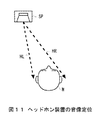
図11に示すように、定位させようとする音源SPがリスナMの前方に位置しているとすると、当該音源SPから出力された音は伝達関数HL及びHRを有する経路を介してリスナMの左耳及び右耳に到達する。このような伝達関数HL及びHRを時間軸に変換した、左チャンネル及び右チャンネルのインパルス応答をあらかじめ測定あるいは計算しておく。 As shown in FIG. 11, if the sound source SP to be localized is located in front of the listener M, the sound output from the sound source SP is transmitted to the listener M through a path having transfer functions HL and HR. Reach the left and right ears. The impulse responses of the left channel and the right channel obtained by converting such transfer functions HL and HR into the time axis are measured or calculated in advance.
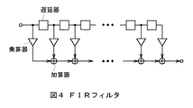
ディジタル処理回路3L及び3Rは、ディジタルオーディオ信号SDに対してそれぞれ上述した左チャンネル及び右チャンネルのインパルス応答を畳み込み、ディジタルオーディオ信号SDL及びSDRとして出力する。ちなみに、ディジタル処理回路3L及び3Rは、例えば図12に示すようなFIR(Finite Impulse Response)フィルタで構成される。
The
ディジタルアナログ変換回路4L及び4Rは、それぞれディジタルオーディオ信号SDL及びSDRをアナログ変換してアナログオーディオ信号SAL及びSARを生成し、対応するアンプ5L及び5Rで増幅してヘッドホン6に供給する。そしてヘッドホン6の音響ユニット(電気・音響変換素子)6L及び6Rは、それぞれアナログオーディオ信号SAL及びSARを音に変換して出力する。
The digital /
したがってヘッドホン6から出力される左右の再生音は、図11に示す音源SPから伝達関数HL、HRを有する経路をそれぞれ介して到達した音と同等となり、これによりリスナがヘッドホン6を装着してその再生音を聴くとき、その音像は図11に示す音源SPの位置に定位する(すなわち頭外定位)。
Accordingly, the right and left reproduced sounds output from the
次に、多チャンネルのオーディオ信号の音像をそれぞれ頭外定位させるヘッドホン装置101を図13を用いて説明する。このヘッドホン装置101では、3チャンネルのオーディオ信号それぞれを図14に示す音源SPa、SPb及びSPcに対応する位置に頭外定位させる。なお、音源SPaからリスナMの両耳への伝達関数HaL及びHaR、音源SPbからリスナMの両耳への伝達関数HbL及びHbR、音源SPcからリスナMの両耳への伝達関数HcL及びHcRをそれぞれ時間軸に変換したインパルス応答を、あらかじめ測定あるいは計算しておく。
Next, a
図13において、ヘッドホン装置101のアナログディジタル変換回路2aは、入力端子1aを介して入力されたアナログオーディオ信号SAaをディジタル変換してディジタルオーディオ信号SDaを生成し、これを後段のディジタル処理回路3aL及び3aRに供給する。同様にアナログディジタル変換回路2bは、入力端子1bを介して入力されたアナログオーディオ信号SAbをディジタル変換してディジタルオーディオ信号SDbを生成し、これを後段のディジタル処理回路3bL及び3bRに供給する。またアナログディジタル変換回路2cは、入力端子1cを介して入力されたアナログオーディオ信号SAcをディジタル変換してディジタルオーディオ信号SDcを生成し、これを後段のディジタル処理回路3cL及び3cRに供給する。
In FIG. 13, the analog-
ディジタル処理回路3aL、3bL及び3cLは、それぞれディジタルオーディオ信号SDa、SDb及びSDcに対して左耳へのインパルス応答を畳み込み、ディジタルオーディオ信号SDaL、SDbL及びSDcLとして加算回路7Lに供給する。同様にディジタル処理回路3aR、3bR及び3cRは、それぞれディジタルオーディオ信号SDa、SDb及びSDcに対して右耳へのインパルス応答を畳み込み、ディジタルオーディオ信号SDaR、SDbR及びSDcRとして加算回路7Rに供給する。各ディジタル処理回路3aL及び3aR、3bL及び3bR、3cL及び3cRは、いずれも図10に示すディジタル処理回路3L及び3Rと同様のFIRフィルタで構成される。
The digital processing circuits 3aL, 3bL, and 3cL convolve impulse responses to the left ear with the digital audio signals SDa, SDb, and SDc, respectively, and supply them to the
加算回路7Lは、インパルス応答が畳み込まれたディジタルオーディオ信号SDaL、SDbL及びSDcLを加算して左チャンネルのディジタルオーディオ信号SDLを生成する。同様に加算回路7Rは、インパルス応答が畳み込まれたディジタルオーディオ信号SDaR、SDbR及びSDcRを加算して右チャンネルのディジタルオーディオ信号SDRを生成する。
The
ディジタルアナログ変換回路4L及び4Rは、それぞれディジタルオーディオ信号SDL及びSDRをアナログ変換してアナログオーディオ信号SAL及びSARを生成し、対応するアンプ5L及び5Rで増幅してヘッドホン6に供給する。そしてヘッドホン6の音響ユニット6L及び6Rは、それぞれアナログオーディオ信号SAL及びSARを音に変換して出力する。
The digital /
このときヘッドホン6から出力される左右の再生音は、図14に示す音源SPa、SPb、SPcからそれぞれ伝達関数HaL及びHaR、HbL及びHbR、HcL及びHcRを有する経路を介して到達した音と同等となり、これによりリスナがヘッドホン6を装着してその再生音を聴くとき、その音像は図14に示す音源SPa、SPb、SPcの位置に定位する。なお、4チャンネル以上のオーディオ信号を扱う場合でも同様の方法で音像を頭外に定位させることができる。
At this time, the right and left reproduced sounds output from the
一方、多チャンネルオーディオ信号をスピーカで再生する場合において、リスニングルームの面積的制約等の理由によって、各チャンネルに対応する多数のスピーカを配置できないことがあるという問題がある。このような問題を解決するため、限られた数のスピーカを用いて、多数の音像をリスナの周囲に構成しようとする試みがある。 On the other hand, when a multi-channel audio signal is reproduced by a speaker, there is a problem that a large number of speakers corresponding to each channel may not be arranged due to the area limitation of the listening room. In order to solve such a problem, there is an attempt to construct a large number of sound images around a listener by using a limited number of speakers.
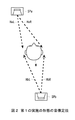
図15は、2個のスピーカ9L及び9Rを用いて任意の位置に音像を定位させるスピーカ装置200を示し、入力端子1を介して入力されたアナログオーディオ信号SAをアナログディジタル変換回路2でディジタル変換してディジタルオーディオ信号SDを生成し、これをディジタル処理回路8L及び8Rに供給する。
FIG. 15 shows a
ディジタル処理回路8L及び8Rは、ディジタルオーディオ信号SDに対してそれぞれ音像定位のためのインパルス応答(後述する)を畳み込み、ディジタルオーディオ信号SDL及びSDRとして出力する。なおディジタル処理回路8L及び8Rは、いずれも図10に示すディジタル処理回路3L及び3Rと同様のFIRフィルタで構成される。
The digital processing circuits 8L and 8R convolve impulse response (described later) for sound image localization with the digital audio signal SD, respectively, and output them as digital audio signals SDL and SDR. Each of the digital processing circuits 8L and 8R is configured by the same FIR filter as the
ディジタルアナログ変換回路4L及び4Rは、それぞれディジタルオーディオ信号SDL及びSDRをアナログ変換してアナログオーディオ信号SAL及びSARを生成し、対応するアンプ5L及び5Rで増幅してスピーカ9L及び9Rに供給する。そしてスピーカ9L及び9Rは、それぞれアナログオーディオ信号SAL及びSARを音に変換して出力する。
The digital /
次に、ディジタル処理回路8L及び8Rにおける音像定位処理の概念を説明する。図16に示すように、リスナMの左前方及び右前方にそれぞれ音源SPL及び音源SPRを配置し、これら音源SPL及びSPRによって、任意の位置に仮想音源SPxを等価的に再現する(定位させる)場合を考える。 Next, the concept of sound image localization processing in the digital processing circuits 8L and 8R will be described. As shown in FIG. 16, a sound source SPL and a sound source SPR are arranged at the left front and right front of the listener M, respectively, and the virtual sound source SPx is equivalently reproduced (localized) at an arbitrary position by these sound sources SPL and SPR. Think about the case.
ここで、伝達関数を
HLL:音源SPLからリスナMの左耳に至る伝達関数
HLR:音源SPLからリスナMの右耳に至る伝達関数
HRL:音源SPRからリスナMの左耳に至る伝達関数
HRR:音源SPRからリスナMの右耳に至る伝達関数
HXL:仮想音源SPXからリスナMの左耳に至る伝達関数
HXR:仮想音源SPXからリスナMの右耳に至る伝達関数
とすると、音源SPL及びSPRは次式のように表すことができる。
Here, the transfer function is HLL: transfer function from the sound source SPL to the left ear of the listener M HLR: transfer function from the sound source SPL to the right ear of the listener M HRL: transfer function from the sound source SPR to the left ear of the listener M HRR: Transfer function from the sound source SPR to the right ear of the listener M HXL: Transfer function from the virtual sound source SPX to the left ear of the listener M HXR: Transfer function from the virtual sound source SPX to the right ear of the listener M It can be expressed as:
SPL=(HXL×HRR−HXR×HRL)/(HLL×HRR−HLR×HRL)×SPX ……(1)
SPR=(HXR×HLL−HXL×HLR)/(HLL×HRR−HLR×HRL)×SPX ……(2)
SPL = (HXL × HRR−HXR × HRL) / (HLL × HRR−HLR × HRL) × SPX (1)
SPR = (HXR × HLL−HXL × HLR) / (HLL × HRR−HLR × HRL) × SPX (2)
したがって、ディジタルオーディオ信号SDに対し、ディジタル処理回路8L及び8Rでそれぞれ(1)式及び(2)式と同様の伝達関数を時間軸に変換したインパルス応答を畳み込むことにより、音像を仮想音源SPxの位置に定位させることができる。 Therefore, by convolving the digital audio signal SD with the impulse response obtained by converting the transfer functions similar to the equations (1) and (2) to the time axis in the digital processing circuits 8L and 8R, respectively, the sound image is converted into the virtual sound source SPx. Can be localized in position.
以上は1チャンネルオーディオ信号の音声を2個のスピーカ9L及び9Rで任意の位置に定位させる場合について述べたが、図13に示した多チャンネル対応のヘッドホン装置101と同様の構成を用いることで、複数チャンネルのオーディオ信号それぞれの音声を2個のスピーカで任意の位置に定位させることができる。
上述したヘッドホン装置やスピーカ装置では、オーディオ信号に対して伝達関数に基づくインパルス応答を畳み込むことにより、音像を任意の位置に定位させることができる。しかしながら、多チャンネルのオーディオ信号それぞれを任意の位置に明瞭な定位感を有する音像として再生しようとした場合、各音源毎に十分な長さのインパルス応答を畳み込む必要があり、このためディジタル処理回路での演算量が膨大になり、これにより装置の構成が複雑になってしまうという問題があった。 In the headphone device or the speaker device described above, a sound image can be localized at an arbitrary position by convolving an impulse response based on a transfer function with respect to an audio signal. However, when trying to reproduce each multi-channel audio signal as a sound image having a clear sense of localization at an arbitrary position, it is necessary to convolve an impulse response with a sufficient length for each sound source. There is a problem in that the amount of computation becomes enormous, which complicates the configuration of the apparatus.
本発明は以上の点を考慮してなされたもので、音像定位のための演算量を従来に比して格段に低減した音像定位装置を提案しようとするものである。 The present invention has been made in consideration of the above points, and an object of the present invention is to propose a sound image localization apparatus in which the amount of calculation for sound image localization is significantly reduced as compared with the conventional art.
かかる課題を解決するため本発明においては、音源定位位置からリスナの左耳及び右耳までのインパルス応答に基づいて左チャンネル及び右チャンネルの定位用オーディオ信号を生成し再生することにより、再生音像を音源定位位置に定位させる音像定位装置において、リスナ前方の音源定位位置に定位させる前方ディジタルオーディオ信号に対し、リスナ前方の音源定位位置からリスナの左耳及び右耳までのインパルス応答に基づいて信号処理を行い、前方定位用ディジタルオーディオ信号を生成する第1の信号処理手段と、リスナ後方の音源定位位置に定位させる後方ディジタルオーディオ信号に対してIIRフィルタを用いてサンプリングレートを1/n(nは2以上の整数)にダウンサンプリングを行うダウンサンプリング手段と、ダウンサンプリング手段によってダウンサンプリングされた後方ディジタルオーディオ信号に対し、リスナ後方の音源定位位置からリスナの左耳及び右耳までのインパルス応答に基づいて信号処理を行い、後方定位用ディジタルオーディオ信号を生成する第2の信号処理手段と、第2の信号処理手段で生成される後方定位用ディジタルオーディオ信号に対してIIRフィルタを用いてサンプリングレートをn倍にアップサンプリングを行うアップサンプリング手段と、第1の信号処理手段からの前方定位用ディジタルオーディオ信号とアップサンプリング手段からの後方定位用ディジタルオーディオ信号とを合成して出力する合成手段とを設けた。 In order to solve such a problem, in the present invention, a reproduced sound image is generated by generating and reproducing left channel and right channel localization audio signals based on impulse responses from the sound source localization position to the left and right ears of the listener. Signal processing based on the impulse response from the sound source localization position in front of the listener to the left and right ears of the listener for the front digital audio signal to be localized in the sound source localization position in front of the listener in the sound image localization device for localization to the sound source localization position And a first digital signal processing means for generating a digital audio signal for front localization and a rear digital audio signal to be localized at a sound source localization position behind the listener using an IIR filter to set the sampling rate to 1 / n (n is a down-sampling means for performing downsampling integer of 2 or more), To the rear digital audio signal down sampled by the down sampling means performs signal processing on the basis of the impulse response from the sound source localization position of the listener behind to the left and right ears of the listener, to generate a digital audio signal for backward localization A second signal processing means; an upsampling means for upsampling a sampling rate n times using an IIR filter with respect to a digital audio signal for rear localization generated by the second signal processing means; provided a synthesizing means for synthesizing and outputting the digital audio signal for backward localization from front localization for digital audio signal and the up-sampling means from the signal processing means.
リスナ後方の音源定位位置に定位させる後方オーディオ信号について、ダウンサンプリングを行った後にインパルス応答に基づく信号処理を行って後方定位用オーディオ信号を生成するようにしたことにより、信号処理手段の演算量を、音像の定位感を損なうことなく低減することができる。 The rear audio signal to be localized at the sound source localization position behind the listener is subjected to signal processing based on the impulse response after down-sampling to generate a rear localization audio signal, thereby reducing the amount of computation of the signal processing means. It can be reduced without impairing the sense of localization of the sound image.
また本発明においては、後方オーディオ信号を前方オーディオ信号から生成するようにした。 In the present invention, the rear audio signal is generated from the front audio signal.
リスナ後方の音源位置に定位させる後方オーディオ信号を前方オーディオ信号から生成し、これをダウンサンプリングした後に信号処理を行って後方定位用オーディオ信号を生成するようにしたことにより、信号処理手段の演算量を、音像の定位感を損なうことなく低減することができる By generating a rear audio signal to be localized at the sound source position behind the listener from the front audio signal, down-sampling this and performing signal processing to generate a rear localization audio signal, the amount of computation of the signal processing means Can be reduced without impairing the localization of the sound image
さらに信号処理手段は、リスナ後方の第1の音源定位位置からリスナの左耳及び右耳までのインパルス応答に基づいてダウンサンプリング後の後方オーディオ信号に対して信号処理することにより、当該第1の音源定位位置に音像が定位する第1の後方定位用オーディオ信号を生成するとともに、当該第1の後方定位用オーディオ信号を反転させることにより、リスナ頭部の正中面を介して当該第1の音源位置の対称位置にある第2の音源定位位置に音像が定位する第2の後方定位用オーディオ信号を生成するようにした。 Furthermore, the signal processing means performs signal processing on the rear audio signal after down-sampling based on the impulse response from the first sound source localization position behind the listener to the left ear and right ear of the listener. A first rear localization audio signal whose sound image is localized at the sound source localization position is generated, and the first rear localization audio signal is inverted to thereby invert the first sound source through the median plane of the listener's head. The second rear localization audio signal is generated in which the sound image is localized at the second sound source localization position at a symmetrical position.
第1の後方定位用オーディオ信号を反転させて第2の後方定位用オーディオ信号を生成することにより、信号処理手段の演算量を格段に低減することができる。 By inverting the first rear localization audio signal and generating the second rear localization audio signal, the amount of calculation of the signal processing means can be significantly reduced.
本発明によれば、音像をリスナの後方に定位させるためインパルス応答に基づく信号処理を行う前に、後方ディジタルオーディオ信号に対してIIRフィルタを用いてサンプリングレートを1/n(nは2以上の整数)にダウンサンプリングを行うと共に、当該インパルス応答に基づく信号処理を行うことにより得られた後方定位用ディジタルオーディオ信号に対してIIRフィルタを用いてサンプリングレートをn倍にアップサンプリングを行うようにしたことにより、音像を後方に定位させるために必要な演算量を大幅に削減して、音像定位装置の構成を簡素化することができる。 According to the present invention, before performing signal processing based on the impulse response to localize the sound image behind the listener , the IIR filter is used for the rear digital audio signal to reduce the sampling rate to 1 / n (n is 2 or more). (Integer) and up-sampling the sampling rate to n times using the IIR filter for the rear localization digital audio signal obtained by performing the signal processing based on the impulse response. As a result, the amount of computation required to localize the sound image backward can be greatly reduced, and the configuration of the sound image localization device can be simplified.
以下図面について、本発明の一実施の形態を詳述する。 Hereinafter, an embodiment of the present invention will be described in detail with reference to the drawings.
(1)第1の実施の形態
(1−1)ヘッドホン装置の全体構成
図10及び図13との共通部分に同一符号を付して示す図1において、10は本発明の第1の実施の形態の音像定位装置としてのヘッドホン装置を示し、入力される2チャンネルのオーディオ信号SAa及びSAbを、それぞれ図2に示す音源SPa及びSPbの位置に頭外定位させるようになされている。なお、音源SPaからリスナMの両耳への伝達関数HaL及びHaR、及び音源SPbからリスナMの両耳への伝達関数HbL及びHbRをそれぞれ時間軸に変換したインパルス応答を、あらかじめ測定あるいは計算しておく。
(1) First Embodiment (1-1) Overall Configuration of Headphone Device In FIG. 1, in which parts that are the same as those in FIGS. 10 and 13 are given the same reference numerals, 10 is the first embodiment of the present invention. 1 shows a headphone device as a sound image localization device of the form, and two-channel input audio signals SAa and SAb are localized outside the head at the positions of sound sources SPa and SPb shown in FIG. The impulse responses obtained by converting the transfer functions HaL and HaR from the sound source SPa to both ears of the listener M and the transfer functions HbL and HbR from the sound source SPb to both ears of the listener M are respectively measured or calculated in advance. Keep it.
ここで、人間の後方から耳への伝達周波数特性(図3(A))は、頭部や耳介の影響によって、前方から耳への伝達周波数特性(図3(B))に比べて、高域の周波数特性が劣化したものになることが知られている(すなわち、後方からの音は高域が低下するということ)。これにより後方定位させるためのインパルス応答は、前方定位させるためのインパルス応答に比べて高域成分を省いたものを用いることができる。 Here, the transfer frequency characteristic from the back of the human to the ear (FIG. 3 (A)) is compared with the transfer frequency characteristic from the front to the ear (FIG. 3 (B)) due to the influence of the head and pinna. It is known that the frequency characteristics of the high range are deteriorated (that is, the high range is reduced for sound from the rear). As a result, the impulse response for rearward localization can be obtained by omitting high frequency components compared to the impulse response for forward localization.
ヘッドホン装置10はこのことを考慮し、後方定位させるための処理を行うディジタル処理回路12bL及び12bRを、前方定位させるための処理を行うディジタル処理回路12aL及び12aRに比べて低いサンプリングレートで動作させるようになされている。
In consideration of this, the
すなわち図1において、音像定位装置としてのヘッドホン装置10のアナログディジタル変換回路2aは、入力端子1aを介して入力されたアナログオーディオ信号SAaを所定のサンプリングレートでディジタル変換してディジタルオーディオ信号SDaを生成し、これを前方定位用のディジタル処理回路12aL及び12aRに供給する。
That is, in FIG. 1, the analog /
ディジタル処理回路12aLはディジタルオーディオ信号SDaに対し、音源SPaからリスナMの左耳への伝達関数HaL(図2)を時間軸に変換したインパルス応答を畳み込み、ディジタルオーディオ信号SDaLとして左チャンネル用の加算回路7Lに供給する。同様にディジタル処理回路12aRはディジタルオーディオ信号SDaに対し、音源SPaからリスナMの右耳への伝達関数HaRを時間軸に変換したインパルス応答を畳み込み、ディジタルオーディオ信号SDaRとして右チャンネル用の加算回路7Rに供給する。
The digital processing circuit 12aL convolves the digital audio signal SDa with an impulse response obtained by converting the transfer function HaL (FIG. 2) from the sound source SPa to the left ear of the listener M into the time axis, and adds the digital audio signal SDaL for the left channel. Supply to the
これに対してアナログディジタル変換回路2bは、入力端子1bを介して入力されたアナログオーディオ信号SAbをアナログディジタル変換回路2aと同じサンプリングレートでディジタル変換してディジタルオーディオ信号SDbを生成し、これをデシメーションフィルタ11に供給する。サンプリングレート変換手段としてのデシメーションフィルタ11は、ディジタルオーディオ信号SDbのサンプリングレートを1/n(nは2以上の整数)にダウンサンプリングし、後方定位用のディジタル処理回路12bL及び12bRに供給する。
On the other hand, the analog /
信号処理手段としてのディジタル処理回路12bLはディジタルオーディオ信号SDbに対し、音源SPbからリスナMの左耳への伝達関数HbL(図2)を時間軸に変換したインパルス応答を畳み込み、ディジタルオーディオ信号SDbLとしてインターポレーションフィルタ13Lに供給する。インターポレーションフィルタ13Lは、ディジタルオーディオ信号SDbLのサンプリングレートをn倍にアップサンプリングすることにより元のディジタルオーディオ信号SDbと同じサンプリングレートに戻し、左チャンネル用の加算回路7Lに供給する。
The digital processing circuit 12bL as the signal processing means convolves the digital audio signal SDb with an impulse response obtained by converting the transfer function HbL (FIG. 2) from the sound source SPb to the left ear of the listener M into the time axis to obtain a digital audio signal SDbL. This is supplied to the interpolation filter 13L. The interpolation filter 13L upsamples the sampling rate of the digital audio signal SDbL by n times to return it to the same sampling rate as that of the original digital audio signal SDb, and supplies the same to the left
同様に信号処理手段としてのディジタル処理回路12bRはディジタルオーディオ信号SDbに対し、音源SPbからリスナMの右耳への伝達関数HbRを時間軸に変換したインパルス応答を畳み込み、ディジタルオーディオ信号SDbRとしてインターポレーションフィルタ13Rに供給する。インターポレーションフィルタ13Rは、ディジタルオーディオ信号SDbRのサンプリングレートをn倍にアップサンプリングすることにより元のディジタルオーディオ信号SDbと同じサンプリングレートに戻し、右チャンネル用の加算回路7Rに供給する。
Similarly, the digital processing circuit 12bR as signal processing means convolves the digital audio signal SDb with an impulse response obtained by converting the transfer function HbR from the sound source SPb to the right ear of the listener M into the time axis, and interpolates as a digital audio signal SDbR. To the
加算回路7Lは、ディジタルオーディオ信号SDaL及びSDbLを加算して左チャンネルのディジタルオーディオ信号SDLを生成する。同様に加算回路7Rは、ディジタルオーディオ信号SDaR及びSDbRを加算して右チャンネルのディジタルオーディオ信号SDRを生成する。
The
ディジタルアナログ変換回路4L及び4Rは、それぞれディジタルオーディオ信号SDL及びSDRをアナログ変換してアナログオーディオ信号SAL及びSARを生成し、対応するアンプ5L及び5Rで増幅してヘッドホン6に供給する。そしてヘッドホン6の音響ユニット6L及び6Rは、それぞれアナログオーディオ信号SAL及びSARを音に変換して出力する。
The digital /
このときヘッドホン6から出力される左右の再生音は、アナログオーディオ信号SAa及びSAbが音源SPa及びSPbの位置(図2)に設置されたスピーカに供給されたときとほぼ同等の音場を構成し、再生音の音像はリスナMの頭外に定位する。
At this time, the left and right reproduced sounds output from the
(1−2)ヘッドホン装置における演算量の削減
ここで、ディジタル処理回路12bL及び12bR、並びに12aL及び12aRは、いずれも図4に示すようなFIRフィルタで構成される。そして、後方定位用のディジタル処理回路12bL及び12bRは、前方定位用のディジタル処理回路12aL及び12aRに比べて1/nのサンプリングレートで動作している。
(1-2) Reduction of Computation Amount in Headphone Device Here, the digital processing circuits 12bL and 12bR, and 12aL and 12aR are all configured by FIR filters as shown in FIG. The rear localization digital processing circuits 12bL and 12bR operate at a sampling rate of 1 / n as compared with the front localization digital processing circuits 12aL and 12aR.
例えばn=2とし、ディジタル処理回路12bL及び12bRのタップ数をTとすると、当該ディジタル処理回路12bL及び12bRはディジタルオーディオ信号SDbの2サンプルにつき2T(=2×T)タップの畳み込み演算を行うことになり、これにより1サンプル当たりではTタップの畳み込み演算を行うことになる。これに対して、もしもダウンサンプリングを行わないとすると、ディジタル処理回路12bL及び12bRのタップ数は2倍の2Tとなり、当該ディジタル処理回路12bL及び12bRはディジタルオーディオ信号SDbの1サンプルにつき4T(=2×2T)タップの畳み込み演算を行うことになる。 For example, if n = 2 and the number of taps of the digital processing circuits 12bL and 12bR is T, the digital processing circuits 12bL and 12bR perform a convolution operation of 2T (= 2 × T) taps for two samples of the digital audio signal SDb. Thus, a T-tap convolution operation is performed per sample. On the other hand, if no downsampling is performed, the number of taps of the digital processing circuits 12bL and 12bR is doubled to 2T, and the digital processing circuits 12bL and 12bR have 4T (= 2 for each sample of the digital audio signal SDb. X2T) Tap convolution is performed.
このようにヘッドホン装置10は、後方定位用のディジタル処理回路12bL及び12bRを1/nのサンプリングレートで動作させることにより、その演算量をダウンサンプリングしない場合の1/n2に低減することができる。
In this way, the
ここで、ディジタル処理回路12bL及び12bRを低サンプリングレートで動作させるためには、上述したようにダウンサンプリングのためのデシメーションフィルタ11及びアップサンプリングのためのインターポレーションフィルタ13L、13Rが必要であり、ヘッドホン装置10の演算量はこれらの分だけ増大することになる。
Here, in order to operate the digital processing circuits 12bL and 12bR at a low sampling rate, the
ところが実際上、デシメーションフィルタ11及びインターポレーションフィルタ13L、13Rはいずれも図5に示すようなIIR(Infinite Impulse Response)フィルタで構成することができる。そして当該デシメーションフィルタ11及びインターポレーションフィルタ13L、13Rは、十分な長さのインパルス応答の畳み込みを行うFIRフィルタ構成のディジタル処理回路12aL、12aR、12bL、12bRに比べて、無視できるほど少ない演算量しか要しない。これによりヘッドホン装置10は、装置全体の演算量を格段に削減することができる。
However, in practice, the
以上の構成によれば、後方定位用のディジタル処理回路12bL及び12bRを1/nのサンプリングレートで動作させることにより、音像の定位感を損なうことなく演算量を削減して、ヘッドホン装置10の構成を簡素化することができる。
According to the above configuration, the digital processing circuits 12bL and 12bR for rear localization are operated at a sampling rate of 1 / n, thereby reducing the amount of computation without impairing the sense of localization of the sound image, and the configuration of the
(2)第2の実施の形態
(2−1)ヘッドホン装置の全体構成
図1との共通部分に同一符号を付して示す図6において、20は本発明の第2の実施の形態の音像定位装置としてのヘッドホン装置を示し、入力される2チャンネルのオーディオ信号SAa及びSAbをそれぞれ図7に示すリスナMの前方左右の音源SPa及びSPbの位置に頭外定位させるとともに、当該オーディオ信号SAa及びSAbから後方用のオーディオ信号SAc及びSAdを生成し、これらをリスナMの後方左右の音源SPc及びSPdの位置にそれぞれ頭外定位させるようになされている。なお、音源SPaからリスナMの両耳への伝達関数HaL及びHaR、音源SPbからリスナMの両耳への伝達関数HbL及びHbR、音源SPcからリスナMの両耳への伝達関数HcL及びHcR、音源SPdからリスナMの両耳への伝達関数HdL及びHdRをそれぞれ時間軸に変換したインパルス応答を、あらかじめ測定あるいは計算しておく。
(2) Second Embodiment (2-1) Overall Configuration of Headphone Device In FIG. 6, in which the same reference numerals are assigned to the common parts with FIG. 1,
ここでこのヘッドホン装置20は、上述したヘッドホン装置10と同様に、オーディオ信号SAc及びSAdを後方定位させるための処理を行うディジタル処理回路12cL、12cR、12dL、12dRを、前方定位させるための処理を行うディジタル処理回路12aL、12aR、12bL、12bRに比べて低いサンプリングレートで動作させることにより、装置全体の演算量を削減するようになされている。
Here, the
すなわち音像定位装置としてのヘッドホン装置20のアナログディジタル変換回路2aは、入力端子1aを介して入力されたアナログオーディオ信号SAaをディジタル変換してディジタルオーディオ信号SDaを生成し、これをディジタル処理回路12aL及び12aR並びに加算回路14c及び14dに供給する。ディジタル処理回路12aLはディジタルオーディオ信号SDaに対し、音源SPaからリスナMの左耳への伝達関数HaL(図7)を時間軸に変換したインパルス応答を畳み込み、ディジタルオーディオ信号SDaLとして左チャンネル用の加算回路7Lに供給する。同様にディジタル処理回路12aRはディジタルオーディオ信号SDaに対し、音源SPaからリスナMの右耳への伝達関数HaRを時間軸に変換したインパルス応答を畳み込み、ディジタルオーディオ信号SDaRとして右チャンネル用の加算回路7Rに供給する。
That is, the analog-
またアナログディジタル変換回路2bは、入力端子1bを介して入力されたアナログオーディオ信号SAbをディジタル変換してディジタルオーディオ信号SDbを生成し、これをディジタル処理回路12bL及び12bR並びに加算回路14c及び14dに供給する。ディジタル処理回路12bLはディジタルオーディオ信号SDbに対し、音源SPbからリスナMの左耳への伝達関数HbLを時間軸に変換したインパルス応答を畳み込み、ディジタルオーディオ信号SDbLとして左チャンネル用の加算回路7Lに供給する。同様にディジタル処理回路12bRはディジタルオーディオ信号SDbに対し、音源SPbからリスナMの右耳への伝達関数HbRを時間軸に変換したインパルス応答を畳み込み、ディジタルオーディオ信号SDbRとして右チャンネル用の加算回路7Rに供給する。
The analog /
加算回路14cは、ディジタルオーディオ信号SDbからディジタルオーディオ信号SDaを減算することにより、図7に示す後方左側の音源SPcに定位させるディジタルオーディオ信号SDcを生成し、デシメーションフィルタ11cに供給する。サンプリングレート変換手段としてのデシメーションフィルタ11cは、ディジタルオーディオ信号SDcのサンプリングレートを1/n(nは2以上の整数)にダウンサンプリングし、後方定位用のディジタル処理回路12cL及び12cRに供給する。
The
信号処理手段としてのディジタル処理回路12cLはディジタルオーディオ信号SDcに対し、音源SPcからリスナMの左耳への伝達関数HcLを時間軸に変換したインパルス応答を畳み込み、ディジタルオーディオ信号SDcLとして加算回路14Lに供給する。同様に信号処理手段としてのディジタル処理回路12cRはディジタルオーディオ信号SDcに対し、音源SPcからリスナMの右耳への伝達関数HcRを時間軸に変換したインパルス応答を畳み込み、ディジタルオーディオ信号SDcRとして加算回路14Rに供給する。 The digital processing circuit 12cL as the signal processing means convolves the digital audio signal SDc with an impulse response obtained by converting the transfer function HcL from the sound source SPc to the left ear of the listener M into the time axis, and the digital audio signal SDcL is added to the adding circuit 14L. Supply. Similarly, the digital processing circuit 12cR as the signal processing means convolves the digital audio signal SDc with an impulse response obtained by converting the transfer function HcR from the sound source SPc to the right ear of the listener M into the time axis, and adds it as a digital audio signal SDcR. 14R.
また加算回路14dは、ディジタルオーディオ信号SDaからディジタルオーディオ信号SDbを減算することにより、右後方の音源SPdに定位させるディジタルオーディオ信号SDdを生成し、デシメーションフィルタ11dに供給する。サンプリングレート変換手段としてのデシメーションフィルタ11dは、ディジタルオーディオ信号SDdのサンプリングレートを1/nにダウンサンプリングし、後方定位用のディジタル処理回路12dL及び12dRに供給する。
The adding
信号処理手段としてのディジタル処理回路12dLはディジタルオーディオ信号SDdに対し、音源SPdからリスナMの左耳への伝達関数HdLを時間軸に変換したインパルス応答を畳み込み、ディジタルオーディオ信号SDdLとして加算回路14Lに供給する。同様に信号処理手段としてのディジタル処理回路12dRはディジタルオーディオ信号SDdに対し、音源SPdからリスナMの右耳への伝達関数HdRを時間軸に変換したインパルス応答を畳み込み、ディジタルオーディオ信号SDdRとして加算回路14Rに供給する。 The digital processing circuit 12dL as the signal processing means convolves the digital audio signal SDd with an impulse response obtained by converting the transfer function HdL from the sound source SPd to the left ear of the listener M into the time axis, and the digital audio signal SDdL is added to the adding circuit 14L. Supply. Similarly, the digital processing circuit 12dR as the signal processing means convolves the digital audio signal SDd with an impulse response obtained by converting the transfer function HdR from the sound source SPd to the right ear of the listener M into the time axis, and adds it as a digital audio signal SDdR. 14R.
加算回路14Lは、ディジタルオーディオ信号SDcL及びSDdLを加算することにより、後方の2つの音源SPc及びSPdから左耳への成分であるディジタルオーディオ信号SDrLを生成し、インターポレーションフィルタ13Lに供給する。インターポレーションフィルタ13Lは、ディジタルオーディオ信号SDrLのサンプリングレートをn倍にアップサンプリングし、左チャンネル用の加算回路7Lに供給する。
The adding circuit 14L adds the digital audio signals SDcL and SDdL to generate a digital audio signal SDrL that is a component from the two rear sound sources SPc and SPd to the left ear and supplies the digital audio signal SDrL to the interpolation filter 13L. The interpolation filter 13L upsamples the sampling rate of the digital audio signal SDrL by n times and supplies it to the
同様に加算回路14Rは、ディジタルオーディオ信号SDcR及びSDdRを加算することにより、後方の2つの音源SPc及びSPdから右耳への成分であるディジタルオーディオ信号SDrRを生成し、インターポレーションフィルタ13Rに供給する。インターポレーションフィルタ13Rは、ディジタルオーディオ信号SDrRのサンプリングレートをn倍にアップサンプリングし、右チャンネル用の加算回路7Rに供給する。
Similarly, the
そして加算回路7Lは、ディジタルオーディオ信号SDaL及びSDbL並びにSDrLを加算して左チャンネルのディジタルオーディオ信号SDLを生成する。同様に加算回路7Rは、ディジタルオーディオ信号SDaR及びSDbR並びにSDrRを加算して右チャンネルのディジタルオーディオ信号SDRを生成する。
The
ディジタルアナログ変換回路4L及び4Rは、それぞれディジタルオーディオ信号SDL及びSDRをアナログ変換してアナログオーディオ信号SAL及びSARを生成し、対応するアンプ5L及び5Rで増幅してヘッドホン6に供給する。そしてヘッドホン6の音響ユニット6L及び6Rは、それぞれアナログオーディオ信号SAL及びSARを音に変換して出力する。
The digital /
このときヘッドホン6から出力される左右の再生音は、図7に示す音源SPa〜SPdに設置されたスピーカとほぼ同等の音場を構成し、再生音の各音像はリスナMの頭外に定位する。
At this time, the left and right reproduced sounds output from the
(2−2)ヘッドホン装置における演算量の削減
上述したように後方定位用のディジタル処理回路12cL、12cR、12dL、12dRは、前方定位用のディジタル処理回路12aL、12aR、12bL、12bRに比べて1/nのサンプリングレートで動作している。
(2-2) Reduction of Computation Amount in Headphone Device As described above, the rear localization digital processing circuits 12cL, 12cR, 12dL, and 12dR are 1 in comparison with the front localization digital processing circuits 12aL, 12aR, 12bL, and 12bR. It operates at a sampling rate of / n.
このためヘッドホン装置20は第1の実施の形態のヘッドホン装置10と同様に、後方定位用のディジタル処理回路12cL、12cR、12dL、12dRの演算量を、ダウンサンプリングしない場合の1/n2に低減することができる。そして、ダウンサンプリングのためのデシメーションフィルタ11c及び11d並びにアップサンプリングのためのインターポレーションフィルタ13L、13Rは、いずれもIIRフィルタで構成することができ、その演算量は無視できるほど少ないものである。
Therefore, similarly to the
以上の構成によれば、後方定位用のディジタル処理回路12cL、12cR、12dL、12dRを1/nのサンプリングレートで動作させることにより、音像の定位感を損なうことなく演算量を削減して、ヘッドホン装置20の構成を簡素化することができる。
According to the above configuration, the digital processing circuits 12cL, 12cR, 12dL, and 12dR for rear localization are operated at a sampling rate of 1 / n, thereby reducing the amount of computation without impairing the sense of localization of the sound image, and the headphones. The configuration of the
(3)第3の実施の形態
上述した第2の実施の形態のヘッドホン装置20では、入力されたオーディオ信号SAa及びSAbから後方用のオーディオ信号SAc及びSAdを生成するようにしたが、当該後方用のオーディオ信号SAc及びSAdを定位させる音源SPc及びSPdの位置(図7)を、リスナMの頭部の正中面に対して左右対称とした場合、後方定位用のディジタル処理回路(図6に示す12cL、12cR、12dL、12dR)をさらに簡略化することができる。
(3) Third Embodiment In the
すなわち図6において、インターポレーションフィルタ13Lから左チャンネル用の加算回路7Lに供給されるディジタルオーディオ信号SDrLは次式で表される。
That is, in FIG. 6, the digital audio signal SDrL supplied from the interpolation filter 13L to the
SDrL=SDcL+SDdL
=SDc×HcL+SDd×HdL
=(SDb−SDa)HcL+(SDa−SDb)HdL
=(SDa−SDb)×(HdL−HcL) ……(3)
SDrL = SDcL + SDdL
= SDc x HcL + SDd x HdL
= (SDb-SDa) HcL + (SDa-SDb) HdL
= (SDa−SDb) × (HdL−HcL) (3)
一方、インターポレーションフィルタ13Rから右チャンネル用の加算回路7Rに供給されるディジタルオーディオ信号SDrRは次式で表される。
On the other hand, the digital audio signal SDrR supplied from the
SDrR=SDcR+SDdR
=SDc×HcR+SDd×HdR
=(SDb−SDa)HcR+(SDa−SDb)HdR
=(SDb−SDa)×(HcR−HdR) ……(4)
SDrR = SDcR + SDdR
= SDc x HcR + SDd x HdR
= (SDb-SDa) HcR + (SDa-SDb) HdR
= (SDb−SDa) × (HcR−HdR) (4)
ここで、上述したように音源SPc及びSPdの位置をリスナMの頭部の正中面に対して左右対称とした場合、HcL=HdR、HcR=HdLとなり、これによりディジタルオーディオ信号SDrL及びSDrRは、次に示す式(5)及び式(6)で表すことができる。 Here, when the positions of the sound sources SPc and SPd are symmetric with respect to the median plane of the head of the listener M as described above, HcL = HdR, HcR = HdL, and thus the digital audio signals SDrL and SDrR are It can represent with the following formula (5) and formula (6).
SDrL=(SDa−SDb)×(HdL−HcL)
=(SDa−SDb)×(HcR−HcL) ……(5)
SDrR=(SDb−SDa)×(HcR−HdR)
=(SDb−SDa)×(HcR−HcL) ……(6)
SDrL = (SDa−SDb) × (HdL−HcL)
= (SDa−SDb) × (HcR−HcL) (5)
SDrR = (SDb−SDa) × (HcR−HdR)
= (SDb−SDa) × (HcR−HcL) (6)
そして、式(5)及び式(6)における伝達関数はいずれも(HcR−HcL)であるから、Hz=HcR−HcL、SDz=SDb−SDaとすると、ディジタルオーディオ信号SDrL及びSDrRは、次に示す式(7)及び式(8)で表すことができる。 Since the transfer functions in the equations (5) and (6) are both (HcR−HcL), assuming that Hz = HcR−HcL and SDz = SDb−SDa, the digital audio signals SDrL and SDrR are It can represent with the formula (7) and formula (8) which are shown.
SDrL=(SDa−SDb)×(HdL−HcL)
=−SDz×Hz ……(7)
SDrR=(SDb−SDa)×(HcR−HcL)
=SDz×Hz ……(8)
SDrL = (SDa−SDb) × (HdL−HcL)
= -SDz x Hz (7)
SDrR = (SDb−SDa) × (HcR−HcL)
= SDz x Hz (8)
このため、ディジタルオーディオ信号SDrRを反転させることでディジタルオーディオ信号SDrRを生成することができ、これによりディジタルオーディオ信号SDrL及びSDrRは1つのディジタル処理回路から生成することができる。 Therefore, the digital audio signal SDrR can be generated by inverting the digital audio signal SDrR, whereby the digital audio signals SDrL and SDrR can be generated from one digital processing circuit.
すなわち図6との共通部分に同一符号を付して示す図8において、30は本発明の第3の実施の形態の音像定位装置としてのヘッドホン装置を示し、アナログディジタル変換回路2a及び2b、並びディジタル処理回路12aL、12aR、12bL、12bRの処理については図6に示すヘッドホン装置20と同一であるため説明を省略する。
That is, in FIG. 8, in which the same reference numerals are assigned to the same parts as in FIG. 6,
加算回路14zは、ディジタルオーディオ信号SDbからディジタルオーディオ信号SDaを減算してディジタルオーディオ信号SDzを生成し、これをデシメーションフィルタ11zに供給する。サンプリングレート変換手段としてのデシメーションフィルタ11zは、ディジタルオーディオ信号SDzのサンプリングレートを1/n(nは2以上の整数)にダウンサンプリングし、後方定位用のディジタル処理回路12zに供給する。
The
信号処理手段としてのディジタル処理回路12zはディジタルオーディオ信号SDzに対し、伝達関数Hz(=HcR−HcL)を時間軸に変換したインパルス応答を畳み込み、右後方のディジタルオーディオ信号SDrRとしてインターポレーションフィルタ13zに供給する。インターポレーションフィルタ13zは、ディジタルオーディオ信号SDrRのサンプリングレートをn倍にアップサンプリングし、右チャンネル用の加算回路7R及び反転回路15に供給する。反転回路15はディジタルオーディオ信号SDrRを反転させることにより左後方のディジタルオーディオ信号SDrLを生成し、左チャンネル用の加算回路7Lに供給する。
The
そして加算回路7Lは、ディジタルオーディオ信号SDaL及びSDbL並びにSDrLを加算して左チャンネルのディジタルオーディオ信号SDLを生成する。同様に加算回路7Rは、ディジタルオーディオ信号SDaR及びSDbR並びにSDrRを加算して右チャンネルのディジタルオーディオ信号SDRを生成する。
The
ディジタルアナログ変換回路4L及び4Rは、それぞれディジタルオーディオ信号SDL及びSDRをアナログ変換してアナログオーディオ信号SAL及びSARを生成し、対応するアンプ5L及び5Rで増幅してヘッドホン6に供給する。そしてヘッドホン6の音響ユニット6L及び6Rは、それぞれアナログオーディオ信号SAL及びSARを音に変換して出力する。
The digital /
このときヘッドホン6から出力される左右の再生音は、図7に示す音源SPa〜SPdに設置されたスピーカとほぼ同等の音場を構成し、再生音の各音像はリスナMの頭外に定位する。
At this time, the left and right reproduced sounds output from the
そしてこのヘッドホン装置30では、第2の実施の形態のヘッドホン装置20における信号処理手段としての4個のディジタル処理回路12cL、12cR、12dL、12dRと等価の処理を、1個のディジタル処理回路12zで行うことができ、これにより、音像の定位感を損なうことなく演算量を格段に削減して、ヘッドホン装置30の構成をさらに簡素化することができる。
In this
(4)他の実施の形態
なお上述の第1乃至第3の実施の形態においては、いずれも音像を頭外定位させるヘッドホン装置に本発明を適用した場合について述べたが、本発明はこれに限らず、図15に示すような、音像を任意の位置に定位させるスピーカ装置に適用することもできる。
(4) Other Embodiments In the first to third embodiments described above, the case where the present invention is applied to a headphone device that localizes a sound image is described. However, the present invention is not limited to this. Not limited to this, the present invention can be applied to a speaker device that localizes a sound image at an arbitrary position as shown in FIG.
また上述の第1乃至第3の実施の形態においては、いずれも後方定位用のディジタル処理回路のサンプリング周波数を整数分の1でダウンサンプリングするようにしたが、本発明はこれに限らず、後方定位用のディジタル処理回路のサンプリング周波数を任意の実数分の1でダウンサンプリングするようにしてもよい。 In the first to third embodiments described above, the sampling frequency of the digital processing circuit for backward localization is down-sampled by 1 / integer. However, the present invention is not limited to this. The sampling frequency of the localization digital processing circuit may be down-sampled by an arbitrary real number.
また上述の第2の実施の形態においては、ディジタルオーディオ信号SDbからディジタルオーディオ信号SDaを減算することにより、音源SPcに定位させるディジタルオーディオ信号SDcを生成するとともに、ディジタルオーディオ信号SDaからディジタルオーディオ信号SDbを減算することにより、音源SPdに定位させるディジタルオーディオ信号SDdを生成し、当該ディジタルオーディオ信号SDc及びディジタルオーディオ信号SDdそれぞれに対してダウンサンプリングした後インパルス応答の畳み込みを行うようにしたが、本発明はこれに限らず、ディジタルオーディオ信号SDcを反転させてディジタルオーディオ信号SDdを生成し、当該ディジタルオーディオ信号SDc及びディジタルオーディオ信号SDdそれぞれに対してダウンサンプリングした後インパルス応答の畳み込みを行うようにしてもよい。さらには、ディジタルオーディオ信号SDcをダウンサンプリングした後反転させ、当該反転させた信号を、ダウンサンプリング後のディジタルオーディオ信号SDdとしてインパルス応答の畳み込みを行うようにしてもよい。これにより、ヘッドホン装置20全体の演算量をさらに削減することができる。
In the second embodiment described above, the digital audio signal SDa to be localized by the sound source SPc is generated by subtracting the digital audio signal SDa from the digital audio signal SDb, and the digital audio signal SDb is generated from the digital audio signal SDa. The digital audio signal SDd to be localized by the sound source SPd is generated by subtracting, and the impulse response is convolved after down-sampling each of the digital audio signal SDc and the digital audio signal SDd. However, the present invention is not limited thereto, and the digital audio signal SDc is generated by inverting the digital audio signal SDc. It may perform convolution of the impulse response after downsampling for each. Furthermore, the digital audio signal SDc may be inverted after being downsampled, and the inverted signal may be convolved with the impulse response as the digital audio signal SDd after downsampling. Thereby, the calculation amount of the
さらに上述の第2及び第3の実施の形態においては、入力された複数のオーディオ信号を加減算することにより後方定位用のオーディオ信号を生成するようにしたが、本発明はこれに限らず、例えば入力されたオーディオ信号の一部帯域を抽出したものを後方定位用のオーディオ信号とする等、種々の方法で後方定位用のオーディオ信号を生成するようにしてもよい。 Further, in the second and third embodiments described above, the audio signal for backward localization is generated by adding and subtracting a plurality of input audio signals. However, the present invention is not limited to this, for example, The rear localization audio signal may be generated by various methods, for example, by extracting a partial band of the input audio signal as an audio signal for rear localization.
さらに上述の第1乃至第3の実施の形態においては、後方定位させるオーディオ信号のダウンサンプリング、インパルス応答の畳み込み及びアップサンプリングといった一連の信号処理を、デシメーションフィルタ、ディジタル処理回路及びインターポレーションフィルタ等のハードウェアで処理するようにしたが、本発明はこれに限らず、これらの一連の音像定位処理を、DSP(Digital Signal Processor)のような情報処理手段上で実行される信号処理プログラムによって処理するようにしてもよい。 Further, in the first to third embodiments described above, a series of signal processing such as down-sampling of the audio signal to be rearranged, convolution of the impulse response, and up-sampling, a decimation filter, a digital processing circuit, an interpolation filter, etc. However, the present invention is not limited to this, and the series of sound image localization processes is processed by a signal processing program executed on an information processing means such as a DSP (Digital Signal Processor). You may make it do.
このような処理をおこなう音像定位処理プログラムを、図9に示すフローチャートを用いて説明する。ヘッドホン装置の情報処理手段は、音像定位処理手順ルーチンRT1の開始ステップから入ってステップSP1に移り、後方定位させるディジタルオーディオ信号をダウンサンプリングして次のステップSP2に移る。 A sound image localization processing program for performing such processing will be described with reference to the flowchart shown in FIG. The information processing means of the headphone device enters from the start step of the sound image localization processing routine RT1 and proceeds to step SP1, down-samples the digital audio signal to be localized backward, and proceeds to the next step SP2.
ステップSP2においてヘッドホン装置の情報処理手段は、予め測定あるいは計算しておいた伝達関数を時間軸に変換したインパルス応答を、ダウンサンプリング後のディジタルオーディオ信号に畳み込み、次のステップSP3に移る。ステップSP3においてヘッドホン装置の情報処理手段は、インパルス応答を畳み込み後のディジタルオーディオ信号を元のサンプリングレートにアップサンプリングして後段の加算回路(図示せず)に出力し、ステップSP1に戻る。 In step SP2, the information processing means of the headphone device convolves the impulse response obtained by converting the transfer function measured or calculated in advance with the time axis into the down-sampled digital audio signal, and proceeds to the next step SP3. In step SP3, the information processing means of the headphone device upsamples the digital audio signal after convolution of the impulse response to the original sampling rate and outputs it to a subsequent addition circuit (not shown), and returns to step SP1.
このように、後方定位させるオーディオ信号に対する信号処理を音像定位処理プログラムで行う場合でも、当該後方定位させるオーディオ信号をダウンサンプリングした後にインパルス応答を畳み込むようにすることにより、情報処理手段の処理負荷を低減することができる。 Thus, even when the signal processing for the audio signal to be localized backward is performed by the sound image localization processing program, the processing load of the information processing means is reduced by convolving the impulse response after downsampling the audio signal to be localized backward. Can be reduced.
本発明は、オーディオ信号の音像を任意の位置に定位させる用途に適用できる。 The present invention can be applied to an application in which a sound image of an audio signal is localized at an arbitrary position.
10、20、30、100、101……ヘッドホン装置、11……デシメーションフィルタ、3、12……ディジタル処理回路、13……インターポレーションフィルタ、200……スピーカ装置。
DESCRIPTION OF
Claims (12)
リスナ前方の音源定位位置に定位させる前方ディジタルオーディオ信号に対し、上記リスナ前方の音源定位位置からリスナの左耳及び右耳までのインパルス応答に基づいて信号処理を行い、前方定位用ディジタルオーディオ信号を生成する第1の信号処理手段と、
リスナ後方の音源定位位置に定位させる後方ディジタルオーディオ信号に対してIIRフィルタを用いてサンプリングレートを1/n(nは2以上の整数)にダウンサンプリングを行うダウンサンプリング手段と、
上記ダウンサンプリング手段によってダウンサンプリングされた上記後方ディジタルオーディオ信号に対し、上記リスナ後方の音源定位位置からリスナの左耳及び右耳までのインパルス応答に基づいて信号処理を行い、後方定位用ディジタルオーディオ信号を生成する第2の信号処理手段と、
上記第2の信号処理手段で生成される上記後方定位用ディジタルオーディオ信号に対してIIRフィルタを用いてサンプリングレートをn倍にアップサンプリングを行うアップサンプリング手段と、
上記第1の信号処理手段からの前方定位用ディジタルオーディオ信号と上記アップサンプリング手段からの後方定位用ディジタルオーディオ信号とを合成して出力する合成手段と
を具えることを特徴とする音像定位装置。 In a sound image localization device that localizes a reproduced sound image to the sound source localization position by generating and reproducing left channel and right channel localization audio signals based on impulse responses from the sound source localization position to the listener's left and right ears ,
For the front digital audio signal to be localized at the sound source localization position in front of the listener, signal processing is performed based on the impulse response from the sound source localization position in front of the listener to the left ear and right ear of the listener, and the digital audio signal for front localization is obtained. First signal processing means to generate;
Down-sampling means for down-sampling the sampling rate to 1 / n (n is an integer of 2 or more) using an IIR filter for the rear digital audio signal to be localized at the sound source localization position behind the listener;
The rear digital audio signal down-sampled by the down-sampling means is subjected to signal processing based on the impulse response from the sound source localization position behind the listener to the left and right ears of the listener, and the digital audio signal for rear localization Second signal processing means for generating
Upsampling means for upsampling the sampling rate to n times using an IIR filter for the backward localization digital audio signal generated by the second signal processing means;
Sound image localization apparatus characterized by comprising a synthesizing means for outputting by synthesizing the digital audio signal for backward localization from front localization for digital audio signal and the up-sampling means from said first signal processing means.
を具えることを特徴とする請求項1に記載の音像定位装置。 Sound image localization apparatus according to claim 1, characterized in that it comprises a rear audio signal generating means for generating the backward digital audio signal from the front digital audio signal.
上記第2の信号処理手段は、ダウンサンプリング後の複数の上記後方ディジタルオーディオ信号それぞれに対して対応する上記インパルス応答に基づいて信号処理を行い上記後方定位用ディジタルオーディオ信号を生成する
ことを特徴とする請求項2に記載の音像定位装置。 The rear audio signal generating means generates a plurality of the rear digital audio signals to be localized at different sound source positions behind the listener from the plurality of front digital audio signals,
The second signal processing means performs signal processing based on the impulse response corresponding to each of the plurality of rear digital audio signals after downsampling to generate the rear localization digital audio signal. The sound image localization apparatus according to claim 2.
ことを特徴とする請求項2に記載の音像定位装置。 The second signal processing means performs signal processing on the rear digital audio signal after downsampling based on an impulse response from the first sound source localization position behind the listener to the left ear and right ear of the listener. And generating a first rear localization digital audio signal whose sound image is localized at the first sound source localization position, and inverting the first rear localization digital audio signal, thereby 3. The sound image localization according to claim 2, further comprising: generating a second rear localization digital audio signal in which the sound image is localized at a second sound source localization position that is symmetrical to the first sound source localization position. apparatus.
リスナ前方の音源定位位置に定位させる前方ディジタルオーディオ信号に対し、上記リスナ前方の音源定位位置からリスナの左耳及び右耳までのインパルス応答に基づいて信号処理を行い、前方定位用ディジタルオーディオ信号を生成する第1の信号処理ステップと、
リスナ後方の音源定位位置に定位させる後方ディジタルオーディオ信号に対してIIRフィルタを用いてサンプリングレートを1/n(nは2以上の整数)にダウンサンプリングを行うダウンサンプリングステップと、
上記ダウンサンプリングステップによってダウンサンプリングされた上記後方ディジタルオーディオ信号に対し、上記リスナ後方の音源定位位置からリスナの左耳及び右耳までのインパルス応答に基づいて信号処理を行い、後方定位用ディジタルオーディオ信号を生成する第2の信号処理ステップと、
上記第2の信号処理ステップで生成される上記後方定位用ディジタルオーディオ信号に対してIIRフィルタを用いてサンプリングレートをn倍にアップサンプリングを行うアップサンプリングステップと、
上記第1の信号処理ステップで生成される前方定位用ディジタルオーディオ信号と上記アップサンプリングステップで生成される後方定位用ディジタルオーディオ信号とを合成して出力する合成ステップと
を具えることを特徴とする音像定位方法。 In a sound image localization method for localizing a reproduced sound image to the sound source localization position by generating and reproducing left channel and right channel localization audio signals based on impulse responses from the sound source localization position to the left and right ears of the listener ,
For the front digital audio signal to be localized at the sound source localization position in front of the listener, signal processing is performed based on the impulse response from the sound source localization position in front of the listener to the left ear and right ear of the listener, and the digital audio signal for front localization is obtained. A first signal processing step to generate;
A downsampling step for downsampling the sampling rate to 1 / n (n is an integer of 2 or more) using an IIR filter for the rear digital audio signal to be localized at the sound source localization position behind the listener;
The rear digital audio signal down-sampled by the down-sampling step is subjected to signal processing based on the impulse response from the sound source localization position behind the listener to the left and right ears of the listener, and the rear localization digital audio signal A second signal processing step for generating
An upsampling step of upsampling a sampling rate n times using an IIR filter with respect to the rear localization digital audio signal generated in the second signal processing step;
And a synthesis step of synthesizing and outputting the front localization digital audio signal generated in the first signal processing step and the rear localization digital audio signal generated in the upsampling step. Sound image localization method.
を具えることを特徴とする請求項5に記載の音像定位方法。 Sound image localization method according to claim 5, characterized in that it comprises a rear audio signal generation step of generating the backward digital audio signal from the front digital audio signal.
ことを特徴とする請求項6に記載の音像定位方法。 The rear audio signal generating step, a plurality of the forward digital audio signal, sound localization according to claim 6, wherein generating a plurality of said rear digital audio signal to be localized at different sound source positions of the listener behind Method.
ことを特徴とする請求項6に記載の音像定位方法。 The second signal processing step performs signal processing on the rear digital audio signal after downsampling based on the impulse response from the first sound source localization position behind the listener to the left ear and right ear of the listener. And generating a first rear localization digital audio signal whose sound image is localized at the first sound source localization position, and inverting the first rear localization digital audio signal, thereby The sound image localization according to claim 6, wherein a second rear localization digital audio signal in which a sound image is localized at a second sound source localization position that is symmetrical to the first sound source localization position is generated. Method.
リスナ前方の音源定位位置に定位させる前方ディジタルオーディオ信号に対し、上記リスナ前方の音源定位位置からリスナの左耳及び右耳までのインパルス応答に基づいて信号処理を行い、前方定位用ディジタルオーディオ信号を生成する第1の信号処理ステップと、
リスナ後方の音源定位位置に定位させる後方ディジタルオーディオ信号に対してIIRフィルタを用いてサンプリングレートを1/n(nは2以上の整数)にダウンサンプリングを行うダウンサンプリングステップと、
上記ダウンサンプリングステップによってダウンサンプリングされた上記後方ディジタルオーディオ信号に対し、上記リスナ後方の音源定位位置からリスナの左耳及び右耳までのインパルス応答に基づいて信号処理を行い、後方定位用ディジタルオーディオ信号を生成する第2の信号処理ステップと、
上記第2の信号処理ステップで生成される上記後方定位用ディジタルオーディオ信号に対してIIRフィルタを用いてサンプリングレートをn倍にアップサンプリングを行うアップサンプリングステップと、
上記第1の信号処理ステップで生成される前方定位用ディジタルオーディオ信号と上記アップサンプリングステップで生成される後方定位用ディジタルオーディオ信号とを合成して出力する合成ステップと
を具えることを特徴とする音像定位プログラム。 A sound image localization program that localizes the reproduced sound image to the sound source localization position by generating and reproducing the left and right channel localization digital audio signals based on the impulse response from the sound source localization position to the left and right ears of the listener. In
For the front digital audio signal to be localized at the sound source localization position in front of the listener, signal processing is performed based on the impulse response from the sound source localization position in front of the listener to the left ear and right ear of the listener, and the digital audio signal for front localization is obtained. A first signal processing step to generate;
A downsampling step for downsampling the sampling rate to 1 / n (n is an integer of 2 or more) using an IIR filter for the rear digital audio signal to be localized at the sound source localization position behind the listener;
The rear digital audio signal down-sampled by the down-sampling step is subjected to signal processing based on the impulse response from the sound source localization position behind the listener to the left and right ears of the listener, and the rear localization digital audio signal A second signal processing step for generating
An upsampling step of upsampling a sampling rate n times using an IIR filter with respect to the rear localization digital audio signal generated in the second signal processing step;
And a synthesis step of synthesizing and outputting the front localization digital audio signal generated in the first signal processing step and the rear localization digital audio signal generated in the upsampling step. Sound image localization program.
を具えることを特徴とする請求項9に記載の音像定位プログラム。 Sound image localization program according to claim 9, characterized in that it comprises a rear audio signal generation step of generating the backward digital audio signal from the front digital audio signal.
ことを特徴とする請求項10に記載の音像定位プログラム。 The rear audio signal generating step, a plurality of the forward digital audio signal, sound localization according to claim 10, wherein generating a plurality of said rear digital audio signal to be localized at different sound source positions of the listener behind program.
ことを特徴とする請求項10に記載の音像定位プログラム。 The second signal processing step performs signal processing on the rear digital audio signal after downsampling based on the impulse response from the first sound source localization position behind the listener to the left ear and right ear of the listener. And generating a first rear localization digital audio signal whose sound image is localized at the first sound source localization position, and inverting the first rear localization digital audio signal, thereby 11. The sound image localization according to claim 10, further comprising: generating a second rear localization digital audio signal in which a sound image is localized at a second sound source localization position that is symmetrical to the first sound source localization position. program.
Priority Applications (5)
| Application Number | Priority Date | Filing Date | Title |
|---|---|---|---|
| JP2004162322A JP4580689B2 (en) | 2004-05-31 | 2004-05-31 | Sound image localization apparatus, sound image localization method, and sound image localization program |
| US11/128,532 US7720241B2 (en) | 2004-05-31 | 2005-05-13 | Sound image localization apparatus and method and recording medium |
| EP05253061A EP1603363A2 (en) | 2004-05-31 | 2005-05-18 | Sound image localization apparatus and method and recording medium |
| KR1020050043733A KR20060048087A (en) | 2004-05-31 | 2005-05-24 | Sound image localization apparatus |
| CN200510075463.5A CN1705408A (en) | 2004-05-31 | 2005-05-31 | Sound image localization apparatus and method and recording medium |
Applications Claiming Priority (1)
| Application Number | Priority Date | Filing Date | Title |
|---|---|---|---|
| JP2004162322A JP4580689B2 (en) | 2004-05-31 | 2004-05-31 | Sound image localization apparatus, sound image localization method, and sound image localization program |
Publications (2)
| Publication Number | Publication Date |
|---|---|
| JP2005347872A JP2005347872A (en) | 2005-12-15 |
| JP4580689B2 true JP4580689B2 (en) | 2010-11-17 |
Family
ID=34941363
Family Applications (1)
| Application Number | Title | Priority Date | Filing Date |
|---|---|---|---|
| JP2004162322A Expired - Fee Related JP4580689B2 (en) | 2004-05-31 | 2004-05-31 | Sound image localization apparatus, sound image localization method, and sound image localization program |
Country Status (5)
| Country | Link |
|---|---|
| US (1) | US7720241B2 (en) |
| EP (1) | EP1603363A2 (en) |
| JP (1) | JP4580689B2 (en) |
| KR (1) | KR20060048087A (en) |
| CN (1) | CN1705408A (en) |
Families Citing this family (5)
| Publication number | Priority date | Publication date | Assignee | Title |
|---|---|---|---|---|
| CN1993002B (en) * | 2005-12-28 | 2010-06-16 | 雅马哈株式会社 | Sound image localization apparatus |
| JP2007202020A (en) * | 2006-01-30 | 2007-08-09 | Sony Corp | Audio signal processing device, audio signal processing method, and program |
| JP5582529B2 (en) * | 2010-06-16 | 2014-09-03 | 日本電信電話株式会社 | Sound source localization method, sound source localization apparatus, and program |
| US9689959B2 (en) * | 2011-10-17 | 2017-06-27 | Foundation de l'Institut de Recherche Idiap | Method, apparatus and computer program product for determining the location of a plurality of speech sources |
| CN104075746B (en) * | 2013-03-29 | 2016-09-07 | 上海航空电器有限公司 | There is the verification method of the virtual sound source locating verification device of azimuth information |
Family Cites Families (11)
| Publication number | Priority date | Publication date | Assignee | Title |
|---|---|---|---|---|
| US5761315A (en) * | 1993-07-30 | 1998-06-02 | Victor Company Of Japan, Ltd. | Surround signal processing apparatus |
| JP2947456B2 (en) | 1993-07-30 | 1999-09-13 | 日本ビクター株式会社 | Surround signal processing device and video / audio reproduction device |
| JPH07184299A (en) | 1993-12-22 | 1995-07-21 | Matsushita Electric Ind Co Ltd | On-vehicle sound field correction device |
| JPH0928000A (en) | 1995-07-12 | 1997-01-28 | Matsushita Electric Ind Co Ltd | Signal processing unit |
| JP2731751B2 (en) | 1995-07-17 | 1998-03-25 | 有限会社井藤電機鉄工所 | Headphone equipment |
| JPH1042400A (en) | 1996-07-25 | 1998-02-13 | Sanyo Electric Co Ltd | Sound image control method and sound image controller |
| TW379512B (en) * | 1997-06-30 | 2000-01-11 | Matsushita Electric Ind Co Ltd | Apparatus for localization of a sound image |
| JP3596296B2 (en) | 1998-08-06 | 2004-12-02 | 松下電器産業株式会社 | Sound field reproducing apparatus and method |
| JP2001186600A (en) | 1999-12-24 | 2001-07-06 | Matsushita Electric Ind Co Ltd | Sound image localization device |
| JP4737804B2 (en) * | 2000-07-25 | 2011-08-03 | ソニー株式会社 | Audio signal processing apparatus and signal processing apparatus |
| JP3874099B2 (en) | 2002-03-18 | 2007-01-31 | ソニー株式会社 | Audio playback device |
-
2004
- 2004-05-31 JP JP2004162322A patent/JP4580689B2/en not_active Expired - Fee Related
-
2005
- 2005-05-13 US US11/128,532 patent/US7720241B2/en not_active Expired - Fee Related
- 2005-05-18 EP EP05253061A patent/EP1603363A2/en not_active Withdrawn
- 2005-05-24 KR KR1020050043733A patent/KR20060048087A/en not_active Application Discontinuation
- 2005-05-31 CN CN200510075463.5A patent/CN1705408A/en active Pending
Also Published As
| Publication number | Publication date |
|---|---|
| KR20060048087A (en) | 2006-05-18 |
| JP2005347872A (en) | 2005-12-15 |
| US20050265557A1 (en) | 2005-12-01 |
| EP1603363A2 (en) | 2005-12-07 |
| US7720241B2 (en) | 2010-05-18 |
| CN1705408A (en) | 2005-12-07 |
Similar Documents
| Publication | Publication Date | Title |
|---|---|---|
| JP5540581B2 (en) | Audio signal processing apparatus and audio signal processing method | |
| KR100739776B1 (en) | Method and apparatus for reproducing a virtual sound of two channel | |
| KR100644617B1 (en) | Apparatus and method for reproducing 7.1 channel audio | |
| KR100677119B1 (en) | Apparatus and method for reproducing wide stereo sound | |
| US7826630B2 (en) | Sound image localization apparatus | |
| JP2009194682A (en) | Head transfer function measuring method, and head transfer function convolution method and apparatus | |
| JP3513850B2 (en) | Sound image localization processing apparatus and method | |
| JP3557177B2 (en) | Stereophonic device for headphone and audio signal processing program | |
| JP2008502200A (en) | Wide stereo playback method and apparatus | |
| WO1999035885A1 (en) | Sound image localizing device | |
| JP4434707B2 (en) | Digital signal processing device, digital signal processing method, and headphone device | |
| JP4744695B2 (en) | Virtual sound source device | |
| US7720241B2 (en) | Sound image localization apparatus and method and recording medium | |
| JPH09327099A (en) | Acoustic reproduction device | |
| JP2003274493A (en) | Sound reproducing apparatus | |
| KR100630436B1 (en) | Digital signal processing circuit and audio reproducing device using it | |
| KR20060048520A (en) | Sound image localization apparatus | |
| JPH09233599A (en) | Device and method for localizing sound image | |
| JP2910891B2 (en) | Sound signal processing device | |
| JP2001186600A (en) | Sound image localization device | |
| JP2642857B2 (en) | Acoustic crosstalk control device | |
| JP2007202020A (en) | Audio signal processing device, audio signal processing method, and program | |
| JP2003111198A (en) | Voice signal processing method and voice reproducing system | |
| JP3925633B2 (en) | Audio playback device |
Legal Events
| Date | Code | Title | Description |
|---|---|---|---|
| A977 | Report on retrieval |
Free format text: JAPANESE INTERMEDIATE CODE: A971007 Effective date: 20061215 |
|
| A131 | Notification of reasons for refusal |
Free format text: JAPANESE INTERMEDIATE CODE: A131 Effective date: 20061222 |
|
| A521 | Request for written amendment filed |
Free format text: JAPANESE INTERMEDIATE CODE: A523 Effective date: 20070209 |
|
| A02 | Decision of refusal |
Free format text: JAPANESE INTERMEDIATE CODE: A02 Effective date: 20071109 |
|
| A521 | Request for written amendment filed |
Free format text: JAPANESE INTERMEDIATE CODE: A523 Effective date: 20080109 |
|
| A521 | Request for written amendment filed |
Free format text: JAPANESE INTERMEDIATE CODE: A523 Effective date: 20080221 |
|
| A911 | Transfer to examiner for re-examination before appeal (zenchi) |
Free format text: JAPANESE INTERMEDIATE CODE: A911 Effective date: 20080226 |
|
| A912 | Re-examination (zenchi) completed and case transferred to appeal board |
Free format text: JAPANESE INTERMEDIATE CODE: A912 Effective date: 20080606 |
|
| A01 | Written decision to grant a patent or to grant a registration (utility model) |
Free format text: JAPANESE INTERMEDIATE CODE: A01 |
|
| R155 | Notification before disposition of declining of application |
Free format text: JAPANESE INTERMEDIATE CODE: R155 |
|
| A61 | First payment of annual fees (during grant procedure) |
Free format text: JAPANESE INTERMEDIATE CODE: A61 Effective date: 20100830 |
|
| FPAY | Renewal fee payment (event date is renewal date of database) |
Free format text: PAYMENT UNTIL: 20130903 Year of fee payment: 3 |
|
| FPAY | Renewal fee payment (event date is renewal date of database) |
Free format text: PAYMENT UNTIL: 20130903 Year of fee payment: 3 |
|
| LAPS | Cancellation because of no payment of annual fees |