JP4579005B2 - In-subject information acquisition device storage case - Google Patents
In-subject information acquisition device storage case Download PDFInfo
- Publication number
- JP4579005B2 JP4579005B2 JP2005047604A JP2005047604A JP4579005B2 JP 4579005 B2 JP4579005 B2 JP 4579005B2 JP 2005047604 A JP2005047604 A JP 2005047604A JP 2005047604 A JP2005047604 A JP 2005047604A JP 4579005 B2 JP4579005 B2 JP 4579005B2
- Authority
- JP
- Japan
- Prior art keywords
- holding
- holding means
- information acquiring
- capsule endoscope
- acquiring apparatus
- Prior art date
- Legal status (The legal status is an assumption and is not a legal conclusion. Google has not performed a legal analysis and makes no representation as to the accuracy of the status listed.)
- Expired - Fee Related
Links
Images


Classifications
-
- A—HUMAN NECESSITIES
- A61—MEDICAL OR VETERINARY SCIENCE; HYGIENE
- A61B—DIAGNOSIS; SURGERY; IDENTIFICATION
- A61B1/00—Instruments for performing medical examinations of the interior of cavities or tubes of the body by visual or photographical inspection, e.g. endoscopes; Illuminating arrangements therefor
- A61B1/04—Instruments for performing medical examinations of the interior of cavities or tubes of the body by visual or photographical inspection, e.g. endoscopes; Illuminating arrangements therefor combined with photographic or television appliances
- A61B1/041—Capsule endoscopes for imaging
-
- A—HUMAN NECESSITIES
- A61—MEDICAL OR VETERINARY SCIENCE; HYGIENE
- A61B—DIAGNOSIS; SURGERY; IDENTIFICATION
- A61B1/00—Instruments for performing medical examinations of the interior of cavities or tubes of the body by visual or photographical inspection, e.g. endoscopes; Illuminating arrangements therefor
- A61B1/00142—Instruments for performing medical examinations of the interior of cavities or tubes of the body by visual or photographical inspection, e.g. endoscopes; Illuminating arrangements therefor with means for preventing contamination, e.g. by using a sanitary sheath
- A61B1/00144—Hygienic packaging
Landscapes
- Health & Medical Sciences (AREA)
- Life Sciences & Earth Sciences (AREA)
- Surgery (AREA)
- Biomedical Technology (AREA)
- Medical Informatics (AREA)
- Optics & Photonics (AREA)
- Pathology (AREA)
- Radiology & Medical Imaging (AREA)
- Biophysics (AREA)
- Engineering & Computer Science (AREA)
- Physics & Mathematics (AREA)
- Heart & Thoracic Surgery (AREA)
- Nuclear Medicine, Radiotherapy & Molecular Imaging (AREA)
- Molecular Biology (AREA)
- Animal Behavior & Ethology (AREA)
- General Health & Medical Sciences (AREA)
- Public Health (AREA)
- Veterinary Medicine (AREA)
- Measurement Of The Respiration, Hearing Ability, Form, And Blood Characteristics Of Living Organisms (AREA)
- Endoscopes (AREA)
Description
本発明は、被検体内に導入されて被検体内部の画像情報を取得する被検体内情報取得装置、たとえば飲み込み型のカプセル型内視鏡を収容するカプセル型内視鏡の収容ケースに関するものである。 BACKGROUND OF THE INVENTION 1. Field of the Invention The present invention relates to an in-subject information acquisition apparatus that is introduced into a subject and acquires image information inside the subject, for example, a capsule endoscope housing case that houses a swallowable capsule endoscope. is there.
近年、内視鏡の分野では、撮像機能と無線機能とが装備されたカプセル型内視鏡が登場している。このカプセル型内視鏡は、観察(検査)のために被検体である被検者に飲み込まれた後、被検者の生体から自然排出されるまでの観察期間、胃、小腸などの臓器の内部(体腔内)をその蠕動運動に伴って移動し、撮像機能を用いて順次撮像する構成である。 In recent years, in the field of endoscopes, capsule endoscopes equipped with an imaging function and a wireless function have appeared. This capsule endoscope is used for observation (examination) after being swallowed by the subject, and during the observation period until it is naturally discharged from the subject's living body, organs such as the stomach and small intestine The inside (inside the body cavity) moves with the peristaltic motion and sequentially captures images using an imaging function.
また、これら臓器内の移動によるこの観察期間、カプセル型内視鏡によって体腔内で撮像された画像データは、順次無線通信などの無線機能により、被検体の外部に設けられた外部装置に送信され、外部装置内に設けられたメモリに蓄積される。被検者がこの無線機能とメモリ機能を備えた外部装置を携帯することにより、被検者は、カプセル型内視鏡を飲み込んだ後、排出されるまでの観察期間、不自由を被ることなく行動が可能になる。観察後は、医者もしくは看護士によって、外部装置のメモリに蓄積された画像データに基づいて、体腔内の画像をディスプレイなどの表示手段に表示させて診断を行うことができる。 Also, during this observation period due to movement in these organs, image data captured in the body cavity by the capsule endoscope is sequentially transmitted to an external device provided outside the subject by a wireless function such as wireless communication. Are stored in a memory provided in the external device. When the subject carries the external device having the wireless function and the memory function, the subject does not suffer any inconvenience during the observation period from swallowing the capsule endoscope until it is discharged. Action is possible. After observation, a doctor or nurse can make a diagnosis by displaying an image in the body cavity on a display means such as a display based on the image data stored in the memory of the external device.
この種のカプセル型内視鏡では、たとえば特許文献1に示すような飲み込み型のものがあり、カプセル型内視鏡の駆動を制御するため、内部に外部磁場によってオン・オフするリードスイッチを備え、この外部磁場を供給する永久磁石を含むパッケージに収容された構成が提案されている。すなわち、カプセル型内視鏡内に備わるリードスイッチは、一定強度以上の磁場が与えられた環境下では、オフ状態を維持し、外部磁場の強度が低下することによってオンする構造を有する。このため、パッケージに収容されている状態では、カプセル型内視鏡は駆動しない。そして、飲み込み時に、このカプセル型内視鏡をパッケージから取り出すことで、永久磁石から離隔してカプセル型内視鏡が磁力の影響を受けなくなり、駆動を開始する。このような構成を有することによって、パッケージ内に収容された状態では、カプセル型内視鏡の駆動が防止可能となり、パッケージから取り出し後は、カプセル型内視鏡の撮像機能による画像の撮像および無線機能による画像信号の送信が行われていた。 In this type of capsule endoscope, for example, there is a swallow type as shown in Patent Document 1, and in order to control the drive of the capsule endoscope, a reed switch that is turned on / off by an external magnetic field is provided. The structure accommodated in the package containing the permanent magnet which supplies this external magnetic field is proposed. That is, the reed switch provided in the capsule endoscope has a structure in which the reed switch is turned on by maintaining the off state and reducing the strength of the external magnetic field in an environment where a magnetic field having a certain intensity or more is applied. For this reason, in the state accommodated in the package, the capsule endoscope is not driven. When the capsule endoscope is swallowed, the capsule endoscope is taken out of the package, so that it is separated from the permanent magnet so that the capsule endoscope is not affected by the magnetic force and starts to drive. By having such a configuration, the capsule endoscope can be prevented from being driven in the state of being accommodated in the package, and after taking out from the package, the imaging of the image by the imaging function of the capsule endoscope and wireless The image signal was transmitted by the function.
しかしながら、このような装置では、カプセル型内視鏡をパッケージから取り出して被検体内に導入するまでには、ある程度の時間を要することから、その間にカプセル型内視鏡の各機能、たとえば撮像機能や無線機能などが駆動を開始し、この撮像機能によって画像の撮像動作がなされ、さらにこの無線機能によって得られた画像信号の無線送信動作がなされてしまい、このためにカプセル型内視鏡内に蓄積された電力が浪費されるという問題があった。 However, in such an apparatus, since it takes a certain amount of time to take out the capsule endoscope from the package and introduce it into the subject, each function of the capsule endoscope in the meantime, for example, an imaging function The wireless function or the like starts driving, and the image capturing operation is performed by this imaging function, and further, the wireless transmission operation of the image signal obtained by the wireless function is performed. There was a problem that the accumulated electric power was wasted.
本発明は、上記問題に鑑みてなされたものであって、カプセル型内視鏡を固定可能に保持して、たとえば検査時などにカプセル型内視鏡の各機能の駆動開始を確実に行うことができるカプセル型内視鏡の収容ケースを提供することを目的とする。 The present invention has been made in view of the above-described problem, and holds a capsule endoscope in a fixable manner to reliably start driving of each function of the capsule endoscope, for example, at the time of examination. It is an object of the present invention to provide a storage case for a capsule endoscope that can be used.
また、本発明の他の目的は、カプセル型内視鏡の収容ケースをヒートシールする際に、このヒートシールを確実に行うことができるカプセル型内視鏡の収容ケースを提供することにある。 Another object of the present invention is to provide a capsule endoscope housing case capable of reliably performing heat sealing when the capsule endoscope housing case is heat sealed.
上述した課題を解決し、目的を達成するために、本発明にかかるカプセル型内視鏡の収容ケースは、互いの間にカプセル型内視鏡を保持するための保持空間領域を形成し、前記保持空間領域内に前記カプセル型内視鏡を収容して保持する第1および第2の保持手段と、前記第1の保持手段と前記第2の保持手段とを係合させて、一方の前記保持手段に対する他方の前記保持手段の回転を阻止する阻止手段と、を備えることを特徴とする。 In order to solve the above-mentioned problems and achieve the object, a storage case for a capsule endoscope according to the present invention forms a holding space region for holding the capsule endoscope between each other, and The first and second holding means for accommodating and holding the capsule endoscope in the holding space region, the first holding means and the second holding means are engaged, Blocking means for preventing rotation of the other holding means relative to the holding means.
また、請求項2の発明にかかるカプセル型内視鏡の収容ケースは、上記発明において、前記阻止手段は、前記収容ケース内で一方の保持手段に保持され、磁界が加わるとオフ状態から電源供給状態に切り替わるカプセル型内視鏡の電源スイッチに対し、前記保持手段の外部で回転されることによって磁界を加える磁性体の前記回転方向への前記保持手段の回転を少なくとも阻止することを特徴とする。 According to a second aspect of the present invention, there is provided a storage case for the capsule endoscope according to the first aspect, wherein the blocking means is held by one holding means in the storage case, and power is supplied from an off state when a magnetic field is applied. The power switch of the capsule endoscope that switches to a state is at least prevented from rotating the holding means in the rotation direction of the magnetic body that applies a magnetic field by being rotated outside the holding means. .
また、請求項3の発明にかかるカプセル型内視鏡の収容ケースは、上記発明において、前記阻止手段は、前記第1および第2の保持手段のいずれか一方に設けられた凹部と、前記第1および第2の保持手段の他方に設けられ、前記凹部に係合する凸部と、から構成されることを特徴とする。 According to a third aspect of the present invention, there is provided the capsule endoscope housing case according to the above invention, wherein the blocking means includes a recess provided in one of the first and second holding means, And a convex portion that is provided on the other of the first and second holding means and engages with the concave portion.
また、請求項4の発明にかかるカプセル型内視鏡の収容ケースは、上記発明において、前記第1および第2の保持手段は、略同一の取手部をそれぞれ有し、前記阻止手段は、前記第1の保持手段と前記第2の保持手段とを係合された状態で、前記取手部同士を係合させて、一方の前記保持手段に対する他方の前記保持手段の回転を阻止することを特徴とする。 According to a fourth aspect of the present invention, in the capsule endoscope housing case, in the above invention, the first and second holding means each have substantially the same handle, and the blocking means includes the With the first holding means and the second holding means engaged, the handle portions are engaged with each other to prevent rotation of the other holding means with respect to one of the holding means. And
また、請求項5の発明にかかるカプセル型内視鏡の収容ケースは、互いの間にカプセル型内視鏡を保持するための保持空間領域を形成し、前記保持空間領域内に前記カプセル型内視鏡を収容して保持する第1および第2の保持手段と、前記第1および第2の保持手段は、略同一の多角形状に形成され、前記第1の保持手段と前記第2の保持手段とが係合された状態で、一方の前記保持手段に対する他方の前記保持手段の回転を阻止することを特徴とする。 The capsule endoscope housing case according to the invention of claim 5 forms a holding space region for holding the capsule endoscope between each other, and the inside of the capsule type is formed in the holding space region. The first and second holding means for housing and holding the endoscope and the first and second holding means are formed in substantially the same polygonal shape, and the first holding means and the second holding means are formed. The rotation of the other holding means relative to the one holding means is prevented while the means is engaged.
また、請求項6の発明にかかるカプセル型内視鏡の収容ケースは、上記発明において、前記第1および第2の保持手段は、前記収容ケース内で一方の保持手段に保持され、磁界が加わるとオフ状態から電源供給状態に切り替わるカプセル型内視鏡の電源スイッチに対し、前記保持手段の外部で回転されることによって磁界を加える磁性体の前記回転方向への前記保持手段の回転を少なくとも阻止することを特徴とする。 According to a sixth aspect of the present invention, there is provided a storage case for a capsule endoscope according to the first aspect, wherein the first and second holding means are held by one holding means in the storage case, and a magnetic field is applied. And at least preventing rotation of the holding means in the rotation direction of the magnetic body that applies a magnetic field by rotating outside the holding means with respect to the power switch of the capsule endoscope that switches from the OFF state to the power supply state. It is characterized by doing.
本発明にかかるカプセル型内視鏡の収容ケースは、係合させることによって、カプセル型内視鏡を保持するための保持空間領域を形成する第1および第2の保持手段を、阻止手段によって、一方の前記保持手段に対する他方の前記保持手段の回転を阻止することで、カプセル型内視鏡を固定可能に保持して、たとえば検査時などにカプセル型内視鏡の各機能の駆動開始を確実に行うことができるという効果を奏する。 In the capsule endoscope housing case according to the present invention, the first and second holding means for forming the holding space region for holding the capsule endoscope by engaging the holding case with the blocking means, By preventing rotation of the other holding means with respect to one holding means, the capsule endoscope can be fixedly held, for example, to start driving each function of the capsule endoscope at the time of inspection, for example. The effect that it can be performed is produced.
以下に、本発明にかかるカプセル型内視鏡の収容ケースの実施の形態を図1〜図23の図面に基づいて詳細に説明する。なお、本発明は、これらの実施の形態に限定されるものではなく、本発明の要旨を逸脱しない範囲で種々の変更実施の形態が可能である。 Hereinafter, embodiments of a housing case for a capsule endoscope according to the present invention will be described in detail with reference to the drawings of FIGS. The present invention is not limited to these embodiments, and various modifications can be made without departing from the scope of the present invention.
(実施の形態1)
図1は、本発明にかかる無線型被検体内情報取得システムの概念を示すシステム概念図である。図1において、このカプセル型内視鏡システムは、被検体1の体腔内に導入される無線型被検体内情報取得装置としての飲み込み型のカプセル型内視鏡2と、被検体1の外部に配置されて、カプセル型内視鏡2との間で各種の情報を無線通信する体外装置である受信装置3とを備えている。また、無線型被検体内情報取得システムは、受信装置3が受信したデータに基づいて画像表示を行う表示装置4と、受信装置3と表示装置4間でデータの入出力を行う携帯型記録媒体5とを備えている。
(Embodiment 1)
FIG. 1 is a system conceptual diagram showing the concept of a wireless in-vivo information acquiring system according to the present invention. In FIG. 1, this capsule endoscope system includes a
カプセル型内視鏡2は、図2の側断面図に示すように、外装ケースである密閉容器11と、密閉容器11内にあって、たとえば体腔内の被検体部位を照明するための照明光を出射するLEDなどの複数の発光素子20と、照明光による反射光を受光して被検体部位を撮像するCCDやCMOSなどの固体撮像素子22(以下代表して、「CCD22」という)と、このCCD22に被写体の像を結像させる結像レンズ27と、このCCD22で取得した画像情報などをRF信号に変調して送信するRF送信ユニット24と、RF信号の電波を放出する送信アンテナ部25と、電池29などの構成要素を備える。
As shown in the side sectional view of FIG. 2, the
密閉容器11は、人が飲み込める程度の大きさのものであり、略半球状の先端カバー11aと、筒形状の胴部カバー11bとを弾性的に嵌合させて、内部を液密に封止する外装ケースを形成している。先端カバー11aは、略半球状のドーム形状であって、ドームの後側が円形状に開口している。この先端カバー11aは、透明性あるいは透光性を有する透明部材、たとえば光学的性能や強度を確保するのに好ましいシクロオレフィンポリマーあるいはポリカーボネイトなどで成形され、かつその表面を鏡面仕上げ加工が施された後述する鏡面仕上げ部11a1を有し、発光素子20からの照明光を密閉容器11の外部に透過することを可能にするとともに、この照明光による被検体からの反射光を内部に透過することを可能にする。この鏡面仕上げ部11a1は、固体撮像素子22の撮像範囲などによって決まる所定の鏡面仕上げ範囲(図2中、一点鎖線a,aで示す範囲)に形成される。
The
また、胴部カバー11bは、先端カバー11aの後端に位置して、上記構成要素を覆う部材である。この胴部カバー11bは、円筒形状の胴部と、略半球状のドーム形状の後端部を一体に形成し、この胴部の前側が円形状に開口している。この胴部カバー11bは、強度を確保するのに好ましいポリサルフォンなどで形成され、後述する照明手段、撮像手段および電池29を胴部に収容し、無線送信手段を後端部に収容している。
Moreover, the trunk |
カプセル型内視鏡2は、図3のブロック図に示すように、密閉容器11の内部に、照明手段としてのLED20およびLED20の駆動状態を制御するLED駆動回路21と、LED20によって照射された領域からの反射光である体腔内の画像(被検体内情報)を結像レンズ27を介して撮像する撮像手段としてのCCD22およびCCD22の駆動状態を制御するCCD駆動回路23と、無線送信手段としてのRF送信ユニット24および送信アンテナ部25とを備えている。
As shown in the block diagram of FIG. 3, the
また、カプセル型内視鏡2は、これらLED駆動回路21、CCD駆動回路23およびRF送信ユニット24の動作を制御するシステムコントロール回路26を備えることにより、このカプセル型内視鏡2が被検体1内に導入されている間、LED20によって照射された被検部位の画像データをCCD22によって取得するように動作している。この取得された画像データは、さらにRF送信ユニット24によってRF信号に変換され、送信アンテナ部25を介して被検体1の外部に送信されている。さらに、カプセル型内視鏡2は、システムコントロール回路26に電力を供給する電池29を備えており、システムコントロール回路26は、電池29から供給される駆動電力を他の構成要素(機能実行手段)に対して分配する機能を有している。
In addition, the
このシステムコントロール回路26は、たとえば各構成要素と電池29との間に接続された切り替え機能を有するスイッチ素子およびラッチ回路などを備えている。そして、このラッチ回路は、外部からの磁界が加わると、スイッチ素子をオン状態にし、それ以降はこのオン状態を保持して、電池29からの駆動電力をカプセル型内視鏡2内の各構成要素に供給している。なお、この実施の形態では、カプセル型内視鏡2内に備わる撮像機能を有する撮像手段、照明機能を有する照明手段および無線機能を有する無線送信手段を総称して、所定の機能を実行する機能実行手段としている。具体的には、システムコントロール回路26を除いたものは、予め設定された所定の機能を実行する機能実行手段である。
The
受信装置3は、図1に示すように、カプセル型内視鏡2から無線送信された体腔内の画像データを受信する無線受信手段としての機能を有する。この受信装置3は、被検体1に着用されるとともに、図示しない複数の受信用アンテナを有する受信ジャケット31と、受信された無線信号の信号処理などを行う外部装置32とを備える。
As illustrated in FIG. 1, the receiving
表示装置4は、カプセル型内視鏡2によって撮像された体腔内画像などを表示するためのものであり、携帯型記録媒体5によって得られるデータに基づいて画像表示を行うワークステーションなどのような構成を有する。具体的には、表示装置4は、CRTディスプレイ、液晶ディスプレイなどによって直接画像を表示する構成としても良いし、プリンタなどのように、他の媒体に画像を出力する構成としても良い。
The display device 4 is for displaying an in-vivo image captured by the
携帯型記録媒体5は、外部装置32および表示装置4にも接続可能であって、両者に対して装着されて、接続された時に情報の出力または記録が可能な構造を有する。この実施の形態では、携帯型記録媒体5は、カプセル型内視鏡2が被検体1の体腔内を移動している間は、外部装置32に挿入されてカプセル型内視鏡2から送信されるデータを記録する。次に、カプセル型内視鏡2が被検体1から排出された後、つまり、被検体1の内部の撮像が終了した後には、外部装置32から取り出されて表示装置4に挿入され、この表示装置4によって、携帯型記録媒体5に記録されたデータが読み出される構成を有する。たとえば、この携帯型記録媒体5は、コンパクトフラッシュ(登録商標)メモリなどから構成され、外部装置32と表示装置4とのデータの入出力を、携帯型記録媒体5を介して間接的に行うことができ、外部装置32と表示装置4との間が有線で直接接続された場合と異なり、被検体1が体腔内の撮影中に自由に動作することが可能となる。
The portable recording medium 5 can be connected to the external device 32 and the display device 4 and has a structure in which information can be output or recorded when the portable recording medium 5 is attached to and connected to both. In this embodiment, the portable recording medium 5 is inserted into the external device 32 and transmitted from the
ところで、機能実行手段を備えるカプセル型内視鏡は、被検者への使用前には、滅菌されてその滅菌状態を保つ必要がある。そこで、この実施の形態では、上記のカプセル型内視鏡2を滅菌可能な収容ケースに収容している。以下に図4〜図12を用いて、実施の形態1にかかる収容ケースを説明する。ここで、図4は、このカプセル型内視鏡を収容する収容ケースの構成を示す斜視図であり、図5は、図4に示した収容ケースから滅菌シートを取り除いた場合の一例を示す斜視図であり、図6は、図5に示した収容ケースの上面を示す上面図であり、図7は、同じく収容ケースの側面を示す側面図であり、図8は、図5に示した実施の形態1にかかる中蓋部の上面を示す上面図であり、図9は、同じく実施の形態1にかかる中蓋部の側面を示す側面図であり、図10は、図9に示した突出部の拡大したA−A断面を示す断面図であり、図11は、図5に示した収容ケースの上面を示す上面図であり、図12は、図11のB−B断面を示す断面図である。
By the way, the capsule endoscope provided with the function execution means needs to be sterilized and kept in a sterilized state before being used for the subject. Therefore, in this embodiment, the
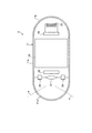
まず、図4および図5において、収容ケース40は、カプセル型内視鏡2を内部に収容可能な外部収容部からなるブリスターパック41と、ブリスターパック41内に備えられ、ブリスターパック41との間でカプセル型内視鏡2を保持する内部収容部からなる中蓋部42と、ブリスターパック41の上面に設けられて、ブリスターパック41の開口を閉塞する滅菌シート43とを備える。なお、ブリスターパック41と中蓋部42とは、第1および第2の保持手段を構成している。
First, in FIGS. 4 and 5, the
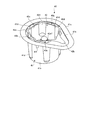
ブリスターパック41は、図6および図7に示すように、有底の円筒部41aと、この円筒部41aの開口上縁の一部に設けられた舌片形状の取手部41bと、この円筒部41aの開口上縁および取手部41bの外周に設けられた縁部41cと、円筒部41aの周面に設けられ、円筒部41aの内部から外部方向に突出した略半円柱形状の複数の突起部41dおよび本発明にかかる凹部としての溝部41fとを備える。
As shown in FIGS. 6 and 7, the
この円筒部41aは、底面41eを有し、この底面41eは、円筒部41aの外周側に設けられた外側底面41e1と、この外側底面41e1の略中央部分に設けられた内側底面41e2とからなる。内側底面41e2は、所定半径の円盤形状に形成され、外側底面41e1は、内側底面41e2の位置から円筒部41aの外部(開口方向と逆方向)に向けて突出した底面からなり、下面が所定の幅を有する中空のドーナツ形状に形成されている。この外側底面41e1と内側底面41e2との間には、図7に示すように、高低差Dが生じている。また、内側底面41e2の中央部分には、内側底面41e2の位置から外側底面41e1方向に向けて窪んだ略半球形状の保持部41e3が設けられている。この保持部41e3は、カプセル型内視鏡2の胴部カバー11bを構成するドーム形状の後端部を保持するためのもので、内側には開口方向に向って十文字形状の突起部41e4が設けられ、線接触で保持された胴部カバー11bの後端部へ滅菌ガスが侵入して、この後端部全体をムラなく滅菌することを可能にしている。なお、この突起部41e4は、複数の突起で構成し、後端部をそれぞれ点接触で保持するように構成することも可能である。
The
取手部41bは、上面が略三角形状の板状部材からなり、図5に示すように、後述する中蓋部42の取手部42bが当接可能に構成されている。縁部41cは、所定の幅を有し、円筒部41aの開口上縁および取手部41bの外周に、階段状に1段高く設けられ、取手部41bに当接した中蓋部42の取手部の動きを抑制している。また、この縁部41cの高さは、取手部41bに当接した中蓋部42の取手部42bや縁部42cの厚みと同等以上に構成されており、この中蓋部42がブリスターパック41内に収容された状態で、縁部41cの上面に滅菌シート43の貼り付けを可能にしている。
The
この突起部41dは、円筒部41aの長手方向に設けられた略半円柱形状の突起からなり、上端(円筒部41aの開口側)の径が最も大きく下端(底面41e側)にいくにしたがって径が徐々に小さくなるように構成され、かつ円筒部41aの長手方向に沿ってそれぞれが略等間隔に配置されている。この突起部41dは、上端が開口し、下端が半ドーム形状の底面を形成している。なお、この実施の形態では、円筒部41aの周面に5つの突起部41dがそれぞれ略等間隔に配置されている。
The
溝部41fは、突起部41dと同様に、円筒部41aの長手方向に設けられた略半円柱形状の溝からなり、上端が円筒部41aの開口に設けられ、上端から下端までの径が同一で、かつ突起部41dの径より小さく構成されている。この溝部41fは、上端が開口し、下端が円筒部41aの長手方向の途中で終端して半ドーム形状の底面を形成しており、中蓋部42がブリスターパック41内に収容された時に、後述する中蓋部42の突起部42fが上下方向に摺動可能に係合するのを可能にしている。この溝部41fは突起部42fとともに、本発明にかかる阻止手段を構成している。なお、この実施の形態では、溝部41fを2つ設けたが、本発明は、これに限らず1つでも、3つ以上であっても良い。また、溝部41fは、実施の形態のように、取手部41bから近い円筒部41aの開口に設けても良いし、取手部41bから遠い円筒部41aの開口に設けても良い。
Similar to the
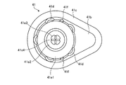
中蓋部42は、図8および図9に示すように、有底の円筒部42aと、この円筒部42aの開口上縁の一部に設けられた舌片形状の取手部42bと、この円筒部41aの開口上縁に取手部42bと連なるように設けられた縁部42cと、円筒部42aの内部から外部方向に突出した略半円柱形状の複数の突起部42dおよび本発明にかかる凸部としての突起部42fとを備える。
As shown in FIGS. 8 and 9, the
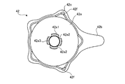
この円筒部42aは、図8〜図12に示すように、底面42eを有し、この底面42eの中央部分には、カプセル型内視鏡2を保持するための孔を有する突出部42e1が設けられている。この突出部42e1は、底面42eの位置から円筒部42aの内部(開口方向)に向けて突出した上面を有する略円筒の断面凸形状に形成されており、その内径は、カプセル型内視鏡2の外径より若干大きい内径で構成されている。この突出部42e1の内周には、突出部42e1の開口に向う長手方向に直線状の突起42e2が複数、この実施の形態では4つ形成されている。また、この突出部42e1の上面側には、段差部42e3が設けられており、この段差部42e3の内径は、突出部42e1の開口側の内径よりも、小さい径で構成されている。図12に示すように、中蓋部42がブリスターパック41内に収容された時に、この円筒部42aの突出部42e1を含む底面42eおよびブリスターパック41の保持部41e3を含む内側底面41e2は、本発明にかかる保持空間領域40aを形成しており、カプセル型内視鏡2を収容して保持することを可能としている。
As shown in FIGS. 8 to 12, the
この実施の形態では、図9、図12に示すように、突出部42e1にカプセル型内視鏡2の先端カバー11a側が挿入された時に、一点鎖線a,aの範囲内の鏡面仕上げ部11a1が突起42e2および段差部42e3を含む突出部42e1の構成部分と非接触な状態になるように、突起42e2が密閉容器11の胴部カバー11bの一部を線接触で保持するとともに、段差部42e3の先端部が先端カバー11aの一部を線接触で保持するように構成されている。なお、これら突起42e2は、突出部42e1の長手方向に直線状に形成させるものに限らず、たとえば突出部42e1に複数の突起部を設け、密閉容器11の胴部カバー11bの一部をそれぞれ点接触で保持するように構成することも可能である。
In this embodiment, as shown in FIGS. 9 and 12, when the
取手部42bは、把持が容易なように、上面が取手部41bより小型の略三角形状の板状部材からなり、図8、図11に示すように、円筒部41aの開口上縁に設けられた縁部42cと一体的に形成されている。この取手部42bは、中蓋部42がブリスターパック41内に収容された時に、ブリスターパック41の取手部41bと当接可能に構成されている。また、縁部42cは、円筒部42aの開口上縁に設けられ、中蓋部42がブリスターパック41内に収容された時に、ブリスターパック41の開口上縁に当接可能に構成されている。上述したように、これら取手部42bおよび縁部42cの厚みは、ブリスターパック41の縁部41cの厚み以下に構成されている。そして、この中蓋部42がブリスターパック41内に収容された時に、縁部41cの上面に滅菌シート43が貼り付けられると、これら取手部42bおよび縁部42cを含む中蓋部42全体が、ブリスターパック41内に収容された状態になる。
The
突起部42dは、円筒部42aの長手方向に設けられた略半円柱形状の突起からなり、円筒部42aの長手方向に沿ってそれぞれが略等間隔に配置されている。この突起部42dは、上端が開口し、下端が半ドーム形状の底面を形成している。なお、この実施の形態では、円筒部42aの周面に5つの突起部42dがそれぞれ略等間隔に配置されている。これら突起部42dは、中蓋部42がブリスターパック41内に収容されて取手部41bと42bが当接した状態で、それぞれがブリスターパック41の突起部41dと対向しない位置で、かつ突起部42dの最突出部分が円筒部41aの内周面と接触可能に形成されて、ブリスターパック41内での中蓋部42のガタツキを防止している。
The
突起部42fは、略半円柱形状の突起部42dのうちの所定突起部42d、この実施の形態では、取手部42bから近い2つの突起部42dの長手方向に設けられた略半円柱形状の突起からなり、上端が突起部42dの開口に設けられ、上端から下端までの径が同一で、かつ溝部41fの径より若干小さく構成されている。この突起部42fは、上端が開口し、下端が突起部42dの長手方向の途中で終端して半ドーム形状の底面を形成しており、中蓋部42がブリスターパック41内に収容された時に、ブリスターパック41の溝部41f内を上下方向に摺動可能に係合している。なお、この突起部42fは、溝部41fに合わせて1つでも、3つ以上であっても良く、取手部42bから遠い突起部42dの開口に設けても良い。
The
図5、図11、図12に示すように、ブリスターパック41の突起部41d内周面と、中蓋部42の円筒部42aの外周面との間には、本発明にかかる空隙による通路40bが形成されており、滅菌シート43を介して外部から侵入した滅菌ガスの通過を可能にしている。また、この通路40bと保持空間領域40aとは互いに連通しており、通路40bを通った滅菌ガスが保持空間領域40aへ到達するのを可能にしている。
As shown in FIGS. 5, 11, and 12, a
また、カプセル型内視鏡2は、図13に示すように、内部に外部からの磁界によってオン/オフ動作を行う電源供給用のリードスイッチ2aを有しており、このリードスイッチ2aがオン状態になって各機能実行手段に電源が供給されたことを、図2に示したLED20の点滅によって外部に知らしめる。このリードスイッチ2aは、カプセル型内視鏡2の長手方向の略中央部に設けられており、リードスイッチ2aから半径r内に、図示しない永久磁石が近づいて所定の磁力が加わると、オンして電源動作が可能な球形状の電源動作可能範囲2bを有している。この実施の形態では、たとえばブリスターパック41の底面41eおよび中蓋部42の底面42eの直径は、この電源動作可能範囲2bの直径2rより長く構成されている。また、この実施の形態では、電源動作可能範囲2bは、カプセル型内視鏡2がブリスターパック41の保持部41e3と中蓋部42の突出部42e1とに保持された時に、内側底面41e2と保持部41e3を含み、かつ外側底面41e1と内側底面41e2の高さの範囲内に設定されるとともに、突出部42e1を含み、かつ円筒部42aの高さの範囲内に設定されている。
Further, as shown in FIG. 13, the
そこで、使用時には、滅菌シート43を収容ケース40から剥離させ、中蓋部42の円筒部42a内側に磁性体(磁石)を収納し、この収納された磁性体の磁界によってリードスイッチをオン状態にし、透明または半透明の突出部42e1からLED20の点滅状態を確認することが可能となる。すなわち、突出部42e1は、カプセル型内視鏡2の保持および保護機能の他に、LEDの点滅確認を容易にするための機能を有している。
Therefore, at the time of use, the
また、カプセル型内視鏡2は、内部に外部からの磁界によってオン/オフ動作を行う電源供給用のリードスイッチ(後述する)を有しており、このリードスイッチがオン状態になって各機能実行手段に電源が供給されたことを、図2に示したLED20の点灯によって外部に知らしめる機能を有する。そこで、この実施の形態では、使用時には、図14、図15に示すようなカプセル型内視鏡用電源スターター(以下、単に「電源スターター」という)51を用いてリードスイッチをオフ状態からオン状態である電源供給状態に切り替える。
The
この電源スターター51は、上部に設けられた取手部51aと、下部に設けられた円筒形状の円筒部51bとから構成され、これら取手部51aと円筒部51bとは一体的に形成されている。また、この円筒部51bの長手方向には、取手部51aの中央部分に貫通する本発明にかかる確認手段としての穴部51cが設けられている。
The
取手部51aは、図14、図15に示すように、上面が略楕円形状に、かつ側面が略台形形状に構成されている。また、円筒部51bは、底面51dの内壁側に磁性体51eが内設されている。図16は、電源スターター51を取り付けた状態での図11のB−B断面を示す断面図である。図16において、穴部51cは、底面51d側の径が中蓋部42の突出部42e1の径よりも若干大きく形成され、かつ穴部51cの途中から上方に向って、この穴部51cの径はテーパー形状に大きく形成されている。また、この穴部の長さは、中蓋部42の突出部42e1の長さよりも長く構成されている。したがって、滅菌シート43が収容ケース40から剥離されると、電源スターター51が中蓋部42の上面側から突出部42e1全体を覆うように係合することが可能となる。なお、この穴部51cの径が上方でテーパー状に大きくなっているのは、カプセル型内視鏡2のLED20が点灯した際に、その確認を容易にするためである。また、逆にこの穴部51cの径を上方でテーパー状に小さくなるように構成し、かつ電源スターター51をたとえば黒っぽい色で形成して、作業者が穴部51cの開口からLED20の点灯を容易に認識することも可能となる。
As shown in FIGS. 14 and 15, the
円筒部51bの外径(直径)は、たとえばリードスイッチ2aの電源動作可能範囲2bの直径2rよりも小さく形成されており、この円筒部51b内に設けられた磁性体51eは、たとえば円筒部51bの内壁と同様に湾曲した所定の大きさの四角形状の磁石から形成されている。この磁性体51eは、電源スターター51が中蓋部42の突出部42e1を覆うように係合すると、電源動作可能範囲2b内に入り、磁性体51eの磁界によってリードスイッチ2aをオン状態にし、穴部51cからLED20の点灯状態を確認することが可能となる。
The outer diameter (diameter) of the
次に、図3に示した実施の形態1にかかるカプセル型内視鏡2のシステムコントロール回路26の回路構成を、図17の回路図を用いて説明する。図17において、システムコントロール回路26は、一端が接地され、かつ他端が後述するラッチ回路と接続される電源供給用スイッチとしてのリードスイッチ2aと、ラッチ回路を構成するフリップフロップ26b,26cと、フリップフロップ26b,26cに接続されてスイッチ素子として機能するFET(電界効果トランジスタ)26d,26eとを備える。リードスイッチ2aは、外部から加わる磁界によってオン/オフ動作を行い、フリップフロップ26b,26cは、このリードスイッチ2aのオン/オフ動作によってクロックが入力すると、FET26d,26eを順次オン状態にセットしている。
Next, the circuit configuration of the
すなわち、外部から磁界が加わると、リードスイッチ2aは、オン動作を行い、図中のa点ではハイ(H)レベルからロー(L)レベルになる。また、磁界が加わらなくなると、リードスイッチ2aは、オフ動作を行い、a点ではLレベルからHレベルに変化する。この動作によりフリップフロップ26bのCK端子にクロックが入力する。フリップフロップ26bでは、a点でのLレベルからHレベルの立ち上がりエッジを分周した信号がQ出力される(b点の信号)。FET26dは、フリップフロップ26bのQ出力がLレベルでオン状態になり、電池29からLED駆動回路21とCCD駆動回路23に電力が供給されて起動し、LED20とCCD22の駆動が可能となり、LED20は点灯する。
That is, when a magnetic field is applied from the outside, the
次に外部から磁界が加わると、a点では、再びHレベルからLレベルになる。この動作によりフリップフロップ26bのQ出力は、Hレベルになり(b点の信号)、FET26dは、オフ状態になって、この回路全体への電力供給が停止して、LED20は消灯する。また次に外部から磁界が加わると、a点では、再びHレベルからLレベルになる。この動作によりフリップフロップ26bのQ出力は、Lレベルになり(b点の信号)、FET26dは、オン状態になって、電池29からLED駆動回路21とCCD駆動回路23に電力が供給されることとなり、LED20が点灯する。このように、FET26dは、リードスイッチ2aに磁界を加えることによって、いわゆるトグル動作でオンすることになる。
Next, when a magnetic field is applied from the outside, at point a, the level changes again from the H level to the L level. By this operation, the Q output of the flip-
また、フリップフロップ26bのQ出力は、RF送信ユニット24のみを起動させるための機能を有するフリップフロップ26cのクロック端子に入力する。フリップフロップ26cでは、b点でのLレベルからHレベルの立ち上がりエッジを分周した信号がQ出力される(c点の信号)。したがって、FET26eは、2回目の磁界印加によるリードスイッチ2aのオン動作によって、オン状態になり、4回目の磁界印加によるリードスイッチ2aのオン動作によって、オフ状態になる。このため、3回目の磁界印加の際に、FET26d,26eがともにオン状態となるので、電池29からRF送信ユニット24にも電力が供給されることとなる。この実施の形態では、たとえば工場出荷時には、上記1回目の磁界印加状態に設定しておいて、被検者への使用時には、3回の磁界印加によって、LED20、CCD22およびRF送信ユニット24全てが駆動可能になるようにするのが好ましい。
The Q output of the flip-
上記の動作を行わせるためには、図18に示すように、リードスイッチ2aが、磁性体51eから発生する磁界Eを切る必要があり、磁力の方向が違うと、磁力がリードスイッチ2aに及ばず、リードスイッチ2aがオン状態に切り替わらなくなる。そこで、この実施の形態では、突出部42e1にカプセル型内視鏡2が保持された状態で、電源スターター51をカプセル型内視鏡2の円周方向に最大90度回転させれば、必ずリードスイッチ2aが磁界Eを切る状態となるので、磁性体51eの磁力がリードスイッチ2aに及んでリードスイッチ2aが電源供給状態になり、LED20を点灯させることができる。
In order to perform the above operation, as shown in FIG. 18, the
このように、この実施の形態では、中蓋部42をブリスターパック41内に収容する際に、図19に示すように、中蓋部42の突起部42fをブリスターパック41の溝部41fに係合させて、中蓋部42をブリスターパック41内に収容させるとともに、製造されたカプセル型内視鏡2を、中蓋部42の底面42eとブリスターパック41の内側底面41e2とによって形成された保持空間領域40aに収容して、保持部41e3および突出部42e1で保持することでカプセル型内視鏡2を収容ケース40内にセットする。次に、この収容ケース40の開口に滅菌シート43をヒートシールした後に、収容ケース40全体をEOG滅菌にかけることで、収容ケース40内部の菌が滅菌され、点接触または線接触で保持空間領域40a内に保持されるカプセル型内視鏡2全体をムラなく、確実に滅菌状態にすることができる。また、この実施の形態では、ヒートシールされた滅菌シート43により新たな菌の収容ケース40内への侵入を防ぐことで、収容ケース内の滅菌状態を保持することができる。
Thus, in this embodiment, when the
次に、カプセル型内視鏡2の電源供給開始動作を、図20のフローチャートに基づいて説明する。図において、まずカプセル型内視鏡2を使用する前には、図4に示した滅菌状態の収容ケース40から滅菌シート43を図5に示すように剥離して(ステップ101)、電源スターター51を中蓋部42に挿入して突出部42e1に取り付ける(ステップ102)。次に、この取り付け状態において、看護士などの作業者が電源スターター51の取手部51aを摘んで、電源スターター51をカプセル型内視鏡2の円周方向に最大90度回転させて、カプセル型内視鏡2のリードスイッチ2aに磁界を加える(ステップ103)。この際に、溝部41fと突起部42fは、係合状態が保たれているので、図11に示すように、ブリスターパック41に対して中蓋部42の回転Fが阻止され、電源スターター51のみを回転させてリードスイッチ2aに磁界を加えることができる。
Next, the power supply start operation of the
このように、電源スターター51によってリードスイッチ2aに磁界が加わると、リードスイッチ2aがオンし、電池29からの電力がLED駆動回路21、CCD駆動回路23及びRF送信ユニット24に供給されて、各機能が駆動してLED20の点灯を初め、CCD22の撮像及びRF送信ユニット24の画像情報の送信が可能となる(ステップ104)。作業者は、LED20の点灯を穴部51cの開口から確認することができる。
As described above, when a magnetic field is applied to the
次に、図19に示すように、中蓋部42の取手部42bを指で摘んで中蓋部42をブリスターパック41内から取り出すと、溝部41f内を突起部42fが摺動して、溝部41fと突起部42fの係合が解除され、カプセル型内視鏡2は、誰の手にも触れられることなく、突出部42e1に保持された状態で取り出される。なお、中蓋部42の取り出しには、たとえば突出部42e1を中蓋部42の内側から指で摘んで取り出すことも可能である。
Next, as shown in FIG. 19, when the
このように、この実施の形態では、ブリスターパックと中蓋部に回転を阻止する溝部と突起部とからなる阻止手段を設けることにより、カプセル型内視鏡を固定可能に保持して、たとえば検査時などに電源スターターでカプセル型内視鏡を起動させる際に、中蓋部が電源スターターと共に空回りすることがなくなり、カプセル型内視鏡の各機能の駆動開始を確実に行うことができる。 Thus, in this embodiment, by providing the blister pack and the inner lid portion with the blocking means including the groove portion and the protruding portion that prevent rotation, the capsule endoscope can be fixedly held, for example, inspection When the capsule endoscope is activated with the power starter at times, the inner lid portion is not idled together with the power starter, and driving of each function of the capsule endoscope can be surely started.
また、この実施の形態では、阻止手段を設けることにより、ブリスターパックをヒートシールする際に、中蓋部が回転して取手部がヒートシールを行うブリスターパックの縁部に乗り上げることがなくなり、カプセル型内視鏡が収容された収容ケースを確実にヒートシールすることができる。 In this embodiment, by providing the blocking means, when the blister pack is heat-sealed, the inner lid portion does not rotate and the handle portion does not ride on the edge of the blister pack where heat-sealing is performed. The housing case in which the mold endoscope is housed can be reliably heat-sealed.
なお、この実施の形態では、凹部としての溝部と、凸部としての突起部を係合させてブリスターパックに対する中蓋部の回転を阻止したが、本発明はこれに限らず、たとえばブリスターパックと中蓋部に設けた凸部同士を係合させて、上記回転を阻止するように構成することも可能である。この場合には、一方方向の回転のみ阻止されることとなるが、電源スターターは、一方方向にのみ回転させてリードスイッチをオン状態にするので、その方向への中蓋部の回転を阻止できるように構成すれば、上記と同様の効果を奏することができる。 In this embodiment, the groove portion as the concave portion and the projection portion as the convex portion are engaged to prevent the rotation of the inner lid portion relative to the blister pack, but the present invention is not limited to this, for example, a blister pack It is also possible to configure so as to prevent the rotation by engaging convex portions provided on the inner lid portion. In this case, only the rotation in one direction is prevented, but the power starter rotates only in one direction to turn on the reed switch, so that the rotation of the inner lid portion in that direction can be prevented. If comprised in this way, there can exist an effect similar to the above.
(実施の形態2)
図21は、収容ケースから滅菌シートを取り除いた場合の実施の形態2を示す斜視図であり、図22は、図21に示した収容ケースの上面を示す上面図である。なお、以下の図において、実施の形態1と同様の構成部分に関しては、説明の都合上、同一符号を付記するものとする。
(Embodiment 2)
FIG. 21 is a perspective view showing the second embodiment when the sterilization sheet is removed from the storage case, and FIG. 22 is a top view showing the top surface of the storage case shown in FIG. In the following drawings, the same components as those in Embodiment 1 are denoted by the same reference numerals for convenience of explanation.
図21、図22において、中蓋部42の取手部42bは、上面がブリスターパック41の取手部41bと略同一の三角形状の板状部材からなり、円筒部41aの開口上縁に設けられた縁部42cと一体的に形成されている。この取手部42bは、中蓋部42がブリスターパック41内に収容された時に、ブリスターパック41の取手部41bと当接可能に構成されている。そして、この中蓋部42がブリスターパック41内に収容された時に、阻止手段を構成する縁部41cによって、取手部42bの動きが制限されるとともに、縁部41cの上面に滅菌シート43が貼り付けられると、これら取手部42bおよび縁部42cを含む中蓋部42全体が、ブリスターパック41内に収容された状態になる。また、中蓋部42の取手部42bを指で摘んで中蓋部42をブリスターパック41内から取り出せば、取手部42bと縁部41cとの係合が解除され、カプセル型内視鏡2は、誰の手にも触れられることなく、突出部42e1に保持された状態で取り出される。
21 and 22, the
このように、この実施の形態では、中蓋部がブリスターパック内に収容された時に、中蓋部とブリスターパックの取手部同士が当接するとともに、ブリスターパックの縁部によって中蓋部の取手部の動き(回転F)が制限されるので、実施の形態1と同様に、カプセル型内視鏡を固定可能に保持して、たとえば検査時などに電源スターターでカプセル型内視鏡を起動させる際に、中蓋部が電源スターターと共に空回りすることがなくなり、カプセル型内視鏡の各機能の駆動開始を確実に行うことができる。 Thus, in this embodiment, when the inner lid portion is housed in the blister pack, the middle lid portion and the handle portion of the blister pack come into contact with each other, and the handle portion of the inner lid portion is formed by the edge of the blister pack. Since the movement (rotation F) of the capsule endoscope is limited, as in the first embodiment, the capsule endoscope is fixedly held and, for example, when starting the capsule endoscope with a power starter at the time of inspection or the like In addition, the inner lid portion is not idled together with the power starter, and the driving of each function of the capsule endoscope can be reliably started.
また、この実施の形態でも、阻止手段を設けることにより、ブリスターパックをヒートシールする際に、中蓋部が回転して取手部がヒートシールを行うブリスターパックの縁部に乗り上げることがなくなり、実施の形態1と同様に、カプセル型内視鏡が収容された収容ケースを確実にヒートシールすることができる。 Also in this embodiment, by providing the blocking means, when the blister pack is heat sealed, the inner lid portion does not rotate and the handle portion does not ride on the edge of the blister pack where heat sealing is performed. As in the first embodiment, the housing case in which the capsule endoscope is housed can be reliably heat-sealed.
(実施の形態3)
図23は、収容ケースから滅菌シートを取り除いた場合の実施の形態3を示す斜視図である。図23において、実施の形態3が実施の形態1と異なる点は、ブリスターパック41が、円筒部41aの代わりに有底の五角柱形状の角柱部41gを備え、中蓋部42が、円筒部42aの代わりに有底の五角柱形状の角柱部42gを備える点である。
(Embodiment 3)
FIG. 23 is a perspective view showing the third embodiment when the sterilization sheet is removed from the housing case. In FIG. 23, the third embodiment differs from the first embodiment in that the
この角柱部41gと42gは、略同一形状で構成されており、このブリスターパック41の角柱部41g内に、中蓋部42の角柱部42gが収容されて、ブリスターパック41に対して中蓋部42の回転Fが阻止されるように、このブリスターパック41と中蓋部42を係合させている。また、中蓋部42の取手部42bを指で摘んで中蓋部42をブリスターパック41内から取り出せば、角柱部同士の係合が解除され、カプセル型内視鏡2は、誰の手にも触れられることなく、突出部42e1に保持された状態で取り出される。なお、ブリスターパック41の角柱部41gには、実施の形態1と同様に、突起部41dを設け、中蓋部42の角柱部42g外周面との間に空隙による通路を形成させて、滅菌ガスの通過を可能にしても良い。
The
このように、この実施の形態では、ブリスターパックと中蓋部が略同一形状に構成され、中蓋部がブリスターパック内に収容された時に、中蓋部とブリスターパックが係合されて、中蓋部の回転が阻止されるので、カプセル型内視鏡を固定可能に保持して、たとえば検査時などに電源スターターでカプセル型内視鏡を起動させる際に、中蓋部が電源スターターと共に空回りすることがなくなり、カプセル型内視鏡の各機能の駆動開始を確実に行うことができる。 Thus, in this embodiment, the blister pack and the inner lid portion are configured to have substantially the same shape, and when the inner lid portion is accommodated in the blister pack, the inner lid portion and the blister pack are engaged, The lid is prevented from rotating, so the capsule endoscope can be held in a fixed manner. For example, when starting the capsule endoscope with a power starter at the time of inspection, the inner lid rotates freely with the power starter. Thus, the driving of each function of the capsule endoscope can be started reliably.
また、ブリスターパックと中蓋部を略同一形状とすることにより、ブリスターパックをヒートシールする際に、中蓋部が回転して取手部がヒートシールを行うブリスターパックの縁部に乗り上げることがなくなり、カプセル型内視鏡が収容された収容ケースを確実にヒートシールすることができる。 Also, by making the blister pack and the inner lid part substantially the same shape, when the blister pack is heat sealed, the inner lid part will not rotate and the handle part will not run over the edge of the blister pack where heat sealing is performed The housing case in which the capsule endoscope is housed can be reliably heat-sealed.
1 被検体
2 カプセル型内視鏡
2a リードスイッチ
2b 電源動作可能範囲
3 受信装置
4 表示装置
5 携帯型記録媒体
11 密閉容器
11a 先端カバー
11a1 鏡面仕上げ部
11b 胴部カバー
20 発光素子(LED)
21 LED駆動回路
22 固体撮像素子
23 CCD駆動回路
24 RF送信ユニット
25 送信アンテナ部
26 システムコントロール回路
26b,26c フリップフロップ
27 結像レンズ
29 電池
31 受信ジャケット
32 外部装置
40 収容ケース
40a 保持空間領域
40b 通路
41 ブリスターパック
41a,42a,51b 円筒部
41b,42b,51a 取手部
41c,42c 縁部
41d,42d,42f,41e4 突起部
41e,42e 底面
41e1 外側底面
41e2 内側底面
41e3 保持部
41f 溝部
41g,42g 角柱部
42 中蓋部
42e1 突出部
42e2 突起
42e3 段差部
43 滅菌シート
51 電源スターター
51c 穴部
51d 底面
51e 磁性体
DESCRIPTION OF SYMBOLS 1
DESCRIPTION OF
Claims (6)
前記第1および第2の保持手段の少なくとも一方の保持手段は、有底の円筒部の中央部分に前記被検体内情報取得装置を保持する突出部が設けられており、前記電源スイッチに対して磁界を加える磁性体を収納した電源スターターを前記突出部を覆うように係合し、当該一方の保持手段及び前記被検体内情報取得装置の外部で回転させて前記電源スイッチを電源供給状態に切り替える際、前記他方の保持手段に対する回転を阻止する阻止手段を有することを特徴とする被検体内情報取得装置の収容ケース。 A holding space region for holding an in-vivo information acquiring apparatus having a power switch that switches from an off state to a power supply state when a magnetic field is applied when they are engaged with each other. First and second holding means for holding and holding the in-vivo information acquiring apparatus inside,
At least one holding means of the first and second holding means is provided with a protruding portion for holding the in-vivo information acquiring apparatus at a central portion of a bottomed cylindrical portion, and the power switch Engage a power starter containing a magnetic material for applying a magnetic field so as to cover the protruding portion, and rotate the power switch to the power supply state by rotating outside the one holding means and the in-vivo information acquiring apparatus. In this case, there is provided a storage case for the in-vivo information acquiring apparatus, characterized in that it has blocking means for blocking rotation relative to the other holding means.
前記第1および第2の保持手段のいずれか一方に設けられた凹部と、
前記第1および第2の保持手段の他方に設けられ、前記凹部に係合する凸部と、
から構成されることを特徴とする請求項1に記載の被検体内情報取得装置の収容ケース。 The blocking means is
A recess provided in any one of the first and second holding means;
A convex portion provided on the other of the first and second holding means and engaged with the concave portion;
The housing case of the in-vivo information acquiring apparatus according to claim 1, comprising:
略同一の取手部をそれぞれ有し、
前記阻止手段は、前記第1の保持手段と前記第2の保持手段とを係合された状態で、前記取手部同士を係合させて、一方の前記保持手段に対する他方の前記保持手段の回転を阻止することを特徴とする請求項1に記載の被検体内情報取得装置の収容ケース。 The first and second holding means are:
Each has approximately the same handle,
The blocking means engages the handle portions in a state where the first holding means and the second holding means are engaged, and rotates the other holding means with respect to one holding means. The housing case for the in-vivo information acquiring apparatus according to claim 1, wherein:
前記第1および第2の保持手段は、略同一の多角形状に形成され、一方が他方の内部に収容される有底の角柱部をそれぞれ有し、
前記第1および第2の保持手段の少なくとも一方の保持手段は、前記有底の角柱部の中央部分に前記被検体内情報取得装置を保持する突出部が設けられており、前記電源スイッチに対して磁界を加える磁性体を収納した電源スターターを前記突出部を覆うように係合し、当該一方の保持手段及び前記被検体内情報取得装置の外部で回転させて前記電源スイッチを電源供給状態に切り替える際、前記角柱部同士が係合して前記一方の保持手段の前記他方の保持手段に対する回転を阻止することを特徴とする被検体内情報取得装置の収容ケース。 A holding space region for holding an in-vivo information acquiring apparatus having a power switch that switches from an off state to a power supply state when a magnetic field is applied when they are engaged with each other. First and second holding means for holding and holding the in-vivo information acquiring apparatus inside,
The first and second holding means are formed in substantially the same polygonal shape, each having a bottomed prismatic part accommodated in the other ,
At least one holding means of the first and second holding means is provided with a protruding portion for holding the in-vivo information acquiring apparatus at a central portion of the bottomed prism portion, with respect to the power switch. Engage a power starter containing a magnetic body to apply a magnetic field so as to cover the protruding portion, and rotate the power switch to a power supply state by rotating the one of the holding means and the in-vivo information acquiring apparatus. An accommodation case for an in-vivo information acquiring apparatus, wherein the prism portions engage with each other to prevent rotation of the one holding means relative to the other holding means when switching.
Priority Applications (1)
| Application Number | Priority Date | Filing Date | Title |
|---|---|---|---|
| JP2005047604A JP4579005B2 (en) | 2005-02-23 | 2005-02-23 | In-subject information acquisition device storage case |
Applications Claiming Priority (1)
| Application Number | Priority Date | Filing Date | Title |
|---|---|---|---|
| JP2005047604A JP4579005B2 (en) | 2005-02-23 | 2005-02-23 | In-subject information acquisition device storage case |
Publications (3)
| Publication Number | Publication Date |
|---|---|
| JP2006230614A JP2006230614A (en) | 2006-09-07 |
| JP2006230614A5 JP2006230614A5 (en) | 2007-03-08 |
| JP4579005B2 true JP4579005B2 (en) | 2010-11-10 |
Family
ID=37038903
Family Applications (1)
| Application Number | Title | Priority Date | Filing Date |
|---|---|---|---|
| JP2005047604A Expired - Fee Related JP4579005B2 (en) | 2005-02-23 | 2005-02-23 | In-subject information acquisition device storage case |
Country Status (1)
| Country | Link |
|---|---|
| JP (1) | JP4579005B2 (en) |
Families Citing this family (1)
| Publication number | Priority date | Publication date | Assignee | Title |
|---|---|---|---|---|
| JP5281966B2 (en) * | 2009-06-23 | 2013-09-04 | オリンパスメディカルシステムズ株式会社 | Capsule type medical device housing case and capsule type medical device power-on method |
Citations (8)
| Publication number | Priority date | Publication date | Assignee | Title |
|---|---|---|---|---|
| US4697703A (en) * | 1986-07-02 | 1987-10-06 | Malcolm Will | Joint prosthesis package |
| JPH10245059A (en) * | 1997-02-18 | 1998-09-14 | Le Creuset Sa | Sealing apparatus |
| JP2000060791A (en) * | 1998-08-26 | 2000-02-29 | Olympus Optical Co Ltd | Endoscope tray |
| JP2003116773A (en) * | 2002-02-18 | 2003-04-22 | Olympus Optical Co Ltd | Hood member mounting tool |
| JP2003523795A (en) * | 1999-11-15 | 2003-08-12 | ギブン・イメージング・リミテツド | How to launch the image acquisition process |
| US20030168370A1 (en) * | 2002-03-08 | 2003-09-11 | Barbara L. Merboth | Package with insert for holding allograft implant to preclude lipid transfer |
| JP2004261240A (en) * | 2003-02-25 | 2004-09-24 | Olympus Corp | Capsule type medical instrument |
| JP2005021651A (en) * | 2003-06-09 | 2005-01-27 | Olympus Corp | Capsule type endoscope system, and capsule type endoscope |
-
2005
- 2005-02-23 JP JP2005047604A patent/JP4579005B2/en not_active Expired - Fee Related
Patent Citations (8)
| Publication number | Priority date | Publication date | Assignee | Title |
|---|---|---|---|---|
| US4697703A (en) * | 1986-07-02 | 1987-10-06 | Malcolm Will | Joint prosthesis package |
| JPH10245059A (en) * | 1997-02-18 | 1998-09-14 | Le Creuset Sa | Sealing apparatus |
| JP2000060791A (en) * | 1998-08-26 | 2000-02-29 | Olympus Optical Co Ltd | Endoscope tray |
| JP2003523795A (en) * | 1999-11-15 | 2003-08-12 | ギブン・イメージング・リミテツド | How to launch the image acquisition process |
| JP2003116773A (en) * | 2002-02-18 | 2003-04-22 | Olympus Optical Co Ltd | Hood member mounting tool |
| US20030168370A1 (en) * | 2002-03-08 | 2003-09-11 | Barbara L. Merboth | Package with insert for holding allograft implant to preclude lipid transfer |
| JP2004261240A (en) * | 2003-02-25 | 2004-09-24 | Olympus Corp | Capsule type medical instrument |
| JP2005021651A (en) * | 2003-06-09 | 2005-01-27 | Olympus Corp | Capsule type endoscope system, and capsule type endoscope |
Also Published As
| Publication number | Publication date |
|---|---|
| JP2006230614A (en) | 2006-09-07 |
Similar Documents
| Publication | Publication Date | Title |
|---|---|---|
| JP4546278B2 (en) | Capsule endoscope power starter | |
| US7766167B2 (en) | Capsule endoscope storage case | |
| EP1834568B1 (en) | Capsule endoscope storage case | |
| WO2008053893A1 (en) | Starter device for electric power source for capsule-type medical device, method of starting capsule-type medical device, and method of stopping electric power source | |
| JP5277321B2 (en) | Power supply starter for capsule medical devices | |
| JP4579038B2 (en) | Storage case for wireless in-vivo information acquisition device | |
| JP4611091B2 (en) | In-subject information acquisition device storage case | |
| JP4632734B2 (en) | Capsule endoscope power starter | |
| JP4520352B2 (en) | Storage case for wireless in-vivo information acquisition device | |
| JP4579005B2 (en) | In-subject information acquisition device storage case | |
| JP4520266B2 (en) | Capsule endoscope storage case | |
| JP2005278815A (en) | Subject internal information acquisition device |
Legal Events
| Date | Code | Title | Description |
|---|---|---|---|
| A521 | Request for written amendment filed |
Free format text: JAPANESE INTERMEDIATE CODE: A523 Effective date: 20070116 |
|
| A621 | Written request for application examination |
Free format text: JAPANESE INTERMEDIATE CODE: A621 Effective date: 20070116 |
|
| A977 | Report on retrieval |
Free format text: JAPANESE INTERMEDIATE CODE: A971007 Effective date: 20091021 |
|
| A131 | Notification of reasons for refusal |
Free format text: JAPANESE INTERMEDIATE CODE: A131 Effective date: 20100223 |
|
| A521 | Request for written amendment filed |
Free format text: JAPANESE INTERMEDIATE CODE: A523 Effective date: 20100421 |
|
| A131 | Notification of reasons for refusal |
Free format text: JAPANESE INTERMEDIATE CODE: A131 Effective date: 20100525 |
|
| A521 | Request for written amendment filed |
Free format text: JAPANESE INTERMEDIATE CODE: A523 Effective date: 20100721 |
|
| TRDD | Decision of grant or rejection written | ||
| A01 | Written decision to grant a patent or to grant a registration (utility model) |
Free format text: JAPANESE INTERMEDIATE CODE: A01 Effective date: 20100817 |
|
| A01 | Written decision to grant a patent or to grant a registration (utility model) |
Free format text: JAPANESE INTERMEDIATE CODE: A01 |
|
| A61 | First payment of annual fees (during grant procedure) |
Free format text: JAPANESE INTERMEDIATE CODE: A61 Effective date: 20100825 |
|
| FPAY | Renewal fee payment (event date is renewal date of database) |
Free format text: PAYMENT UNTIL: 20130903 Year of fee payment: 3 |
|
| R151 | Written notification of patent or utility model registration |
Ref document number: 4579005 Country of ref document: JP Free format text: JAPANESE INTERMEDIATE CODE: R151 |
|
| FPAY | Renewal fee payment (event date is renewal date of database) |
Free format text: PAYMENT UNTIL: 20130903 Year of fee payment: 3 |
|
| S111 | Request for change of ownership or part of ownership |
Free format text: JAPANESE INTERMEDIATE CODE: R313111 |
|
| R350 | Written notification of registration of transfer |
Free format text: JAPANESE INTERMEDIATE CODE: R350 |
|
| S531 | Written request for registration of change of domicile |
Free format text: JAPANESE INTERMEDIATE CODE: R313531 |
|
| R350 | Written notification of registration of transfer |
Free format text: JAPANESE INTERMEDIATE CODE: R350 |
|
| R250 | Receipt of annual fees |
Free format text: JAPANESE INTERMEDIATE CODE: R250 |
|
| R250 | Receipt of annual fees |
Free format text: JAPANESE INTERMEDIATE CODE: R250 |
|
| R250 | Receipt of annual fees |
Free format text: JAPANESE INTERMEDIATE CODE: R250 |
|
| R250 | Receipt of annual fees |
Free format text: JAPANESE INTERMEDIATE CODE: R250 |
|
| LAPS | Cancellation because of no payment of annual fees |