JP4577971B2 - Body box - Google Patents
Body box Download PDFInfo
- Publication number
- JP4577971B2 JP4577971B2 JP2000304475A JP2000304475A JP4577971B2 JP 4577971 B2 JP4577971 B2 JP 4577971B2 JP 2000304475 A JP2000304475 A JP 2000304475A JP 2000304475 A JP2000304475 A JP 2000304475A JP 4577971 B2 JP4577971 B2 JP 4577971B2
- Authority
- JP
- Japan
- Prior art keywords
- plate
- body box
- side walls
- side wall
- piece
- Prior art date
- Legal status (The legal status is an assumption and is not a legal conclusion. Google has not performed a legal analysis and makes no representation as to the accuracy of the status listed.)
- Expired - Fee Related
Links
Images


Description
【0001】
【発明の属する技術分野】
この発明は、ギフト用の詰め合わせ等、商品が密に収納される身箱に関する。
【0002】
【従来の技術】
例えば、缶ビールのギフト包装に際しては、図6に示すような身箱B内に缶Cが密に収納される。この身箱Bは、底面板50の周囲に対向する2組の側壁51を備え、各対の側壁51を底面板50に順次繋がる側面板52、額縁板53及び内側板54から構成し、隣接する側壁51同士を挟持片55を介し係合させて側壁51の起立状態を維持するものであり、その内部には仕切材Sが挿入され、天面は蓋Lを被せて閉止される。
【0003】
【発明が解決しようとする課題】
しかしながら、上記のような身箱Bに隙間なく缶Cを収納すると、缶Cと側壁51の間に指が入らず、最初の缶Cが非常に取り出しにくいため、その改善が望まれている。
【0004】
【課題を解決するための手段】
上記課題を解決するため、この発明は、側壁に設けた揺動片を外側へ倒すことにより、商品と揺動片の間に指が入るようにし、また、揺動片が外側に倒した状態で保持されるようにしたのである。
【0005】
【発明の実施の形態】
以下、この発明の実施の形態を添付図面に基づいて説明する。
【0006】
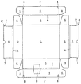
図1に示す身箱Bのブランクでは、底面板1の周縁各辺に側壁2をなす側面板3、額縁板4及び内側板5が順次連設されている。このうち、一対の側壁2において、側面板3の両側縁には挟持片6が連設され、内側板5の両側縁先端部には係合片7が設けられている。また、他対の側壁2において、内側板5の両側縁には挟持片6が連設され、内側板5の先端縁両側部には切込8が設けられている。
【0007】
そして、他対の側壁2をなす部分のうち、一方の部分には、額縁板4から側面板3及び内側板5へかけて2本のミシン目が形成され、その間の部分が揺動片9とされている。この揺動片9では、内側板5の部分が側面板3の部分よりも大きくなっている。
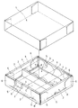
【0008】
このようなブランクを、図2に示す身箱Bに組み立てるには、一対の側壁2の側面板3を起立させ、挟持片6を内側へ折り曲げた状態で、この挟持片6を包み込むように他対の側壁2の側面板3、額縁板4及び内側板5を折り曲げ、その挟持片6を内向させて一対の側壁2の額縁板4及び内側板5で包み込み、係合片7を切込8に差し込む。
【0009】
このように組み立てると、挟持片6のはね上がりが額縁板4で規制され、側壁2の起立状態が維持される。そして、この身箱Bの内部に仕切材Sを挿入し、缶Cを詰め合わせた後、蓋Lを被せて身箱Bの天面を閉止する。
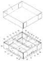
【0010】
一方、身箱Bから缶Cを取り出す際には、蓋Lを取り、図3乃至図5に示すように、ミシン目を切断して揺動片9を外側へ倒すと、揺動片9と缶Cの間に指を入れることができるので、缶Cを容易に取り出すことができる。
【0011】
なお、揺動片9は、内側板5の部分が側面板3の部分よりも大きくなっているので、外側へ倒れた状態で戻ることなく保持され、缶Cを取り出す際、指で支えておく必要がない。
【0012】
また、この身箱Bは、一般の製函機で組み立てることができ、従来の抜型に揺動片9の部分を追加するだけで製造できる。
【0013】
ところで、この実施形態では、一方の側壁2にのみ揺動片9を設けたが、他の側壁2にも揺動片9を設けるようにしてもよい。
【0014】
【発明の効果】
以上のように、この発明に係る身箱は、側壁に設けた揺動片を外側へ倒すことにより、商品と揺動片の間に指が入るようにしたので、容易に商品を取り出すことができ、また、揺動片が外側に倒れた状態で保持されるようにしたので、商品を取り出す際、揺動片を指で支えておく必要もない。
【図面の簡単な説明】
【図1】この発明に係る身箱の一実施形態のブランクを示す図
【図2】同上の包装時の使用状態を示す斜視図
【図3】同上の商品取出時の状態を示す斜視図
【図4】同上の縦断側面図
【図5】同上の一部平面図
【図6】従来の身箱の包装時の使用状態を示す斜視図
【符号の説明】
1 底面板
2 側壁
3 側面板
4 額縁板
5 内側板
6 挟持片
9 揺動片[0001]
BACKGROUND OF THE INVENTION
The present invention relates to a body box in which merchandise is closely stored, such as assortment for gifts.
[0002]
[Prior art]
For example, when canned beer is gift-wrapped, the can C is tightly stored in a body box B as shown in FIG. The body box B includes two sets of
[0003]
[Problems to be solved by the invention]
However, when the can C is stored in the body box B without any gap, no finger can enter between the can C and the
[0004]
[Means for Solving the Problems]
In order to solve the above problems, the present invention is such that the swing piece provided on the side wall is tilted outward so that a finger can enter between the product and the swing piece, and the swing piece is tilted outward. It was made to be held by.
[0005]
DETAILED DESCRIPTION OF THE INVENTION
Embodiments of the present invention will be described below with reference to the accompanying drawings.
[0006]
In the blank of the body box B shown in FIG. 1, a
[0007]
Of the portions forming the other pair of
[0008]
To assemble such a blank into the body box B shown in FIG. 2, the
[0009]
When assembled in this way, the rising of the
[0010]
On the other hand, when removing the can C from the body box B, as shown in FIGS. 3 to 5, when the
[0011]
In addition, since the part of the
[0012]
Further, the body box B can be assembled by a general box making machine, and can be manufactured simply by adding the
[0013]
By the way, in this embodiment, the
[0014]
【The invention's effect】
As described above, the body box according to the present invention allows a finger to be inserted between the product and the swinging piece by tilting the swinging piece provided on the side wall outward, so that the product can be easily taken out. In addition, since the swinging piece is held in a state of falling outward, it is not necessary to support the swinging piece with a finger when taking out the product.
[Brief description of the drawings]
FIG. 1 is a view showing a blank of an embodiment of a body box according to the present invention. FIG. 2 is a perspective view showing a use state at the time of packaging. FIG. 3 is a perspective view showing a state at the time of taking out a product. FIG. 4 is a vertical side view of the same. FIG. 5 is a partial plan view of the same. FIG. 6 is a perspective view showing the state of use of the conventional body box during packaging.
DESCRIPTION OF
Claims (1)
Priority Applications (1)
| Application Number | Priority Date | Filing Date | Title |
|---|---|---|---|
| JP2000304475A JP4577971B2 (en) | 2000-10-04 | 2000-10-04 | Body box |
Applications Claiming Priority (1)
| Application Number | Priority Date | Filing Date | Title |
|---|---|---|---|
| JP2000304475A JP4577971B2 (en) | 2000-10-04 | 2000-10-04 | Body box |
Publications (3)
| Publication Number | Publication Date |
|---|---|
| JP2002104386A JP2002104386A (en) | 2002-04-10 |
| JP2002104386A5 JP2002104386A5 (en) | 2007-11-01 |
| JP4577971B2 true JP4577971B2 (en) | 2010-11-10 |
Family
ID=18785516
Family Applications (1)
| Application Number | Title | Priority Date | Filing Date |
|---|---|---|---|
| JP2000304475A Expired - Fee Related JP4577971B2 (en) | 2000-10-04 | 2000-10-04 | Body box |
Country Status (1)
| Country | Link |
|---|---|
| JP (1) | JP4577971B2 (en) |
Families Citing this family (2)
| Publication number | Priority date | Publication date | Assignee | Title |
|---|---|---|---|---|
| JP4847113B2 (en) * | 2005-11-30 | 2011-12-28 | 柳井紙工株式会社 | Assembled paper box |
| JP2008239223A (en) * | 2007-03-28 | 2008-10-09 | Kyodo Printing Co Ltd | Packaging container |
Citations (8)
| Publication number | Priority date | Publication date | Assignee | Title |
|---|---|---|---|---|
| JPS5811735Y2 (en) * | 1976-02-17 | 1983-03-05 | 松下冷機株式会社 | packing equipment |
| JPS5846730U (en) * | 1981-09-22 | 1983-03-29 | 松下電器産業株式会社 | packaging box |
| JPS6341322Y2 (en) * | 1983-10-31 | 1988-10-28 | ||
| JPH0358221U (en) * | 1989-10-09 | 1991-06-06 | ||
| JPH0733830U (en) * | 1993-12-10 | 1995-06-23 | レンゴー株式会社 | Packaging box for canned beverages |
| JP2520402Y2 (en) * | 1990-07-02 | 1996-12-18 | ザ・パック株式会社 | Wrapping paper box |
| JPH11208643A (en) * | 1998-01-21 | 1999-08-03 | Rengo Co Ltd | Paper case |
| JP2000229623A (en) * | 1999-02-15 | 2000-08-22 | Tomoku Co Ltd | Packaging box |
Family Cites Families (3)
| Publication number | Priority date | Publication date | Assignee | Title |
|---|---|---|---|---|
| JPS60184822U (en) * | 1984-05-21 | 1985-12-07 | 刈谷紙器株式会社 | packaging container |
| JPH01114527U (en) * | 1988-01-26 | 1989-08-01 | ||
| JPH11348963A (en) * | 1998-06-02 | 1999-12-21 | Toshiba Logistics Corp | Built-up box for housing |
-
2000
- 2000-10-04 JP JP2000304475A patent/JP4577971B2/en not_active Expired - Fee Related
Patent Citations (8)
| Publication number | Priority date | Publication date | Assignee | Title |
|---|---|---|---|---|
| JPS5811735Y2 (en) * | 1976-02-17 | 1983-03-05 | 松下冷機株式会社 | packing equipment |
| JPS5846730U (en) * | 1981-09-22 | 1983-03-29 | 松下電器産業株式会社 | packaging box |
| JPS6341322Y2 (en) * | 1983-10-31 | 1988-10-28 | ||
| JPH0358221U (en) * | 1989-10-09 | 1991-06-06 | ||
| JP2520402Y2 (en) * | 1990-07-02 | 1996-12-18 | ザ・パック株式会社 | Wrapping paper box |
| JPH0733830U (en) * | 1993-12-10 | 1995-06-23 | レンゴー株式会社 | Packaging box for canned beverages |
| JPH11208643A (en) * | 1998-01-21 | 1999-08-03 | Rengo Co Ltd | Paper case |
| JP2000229623A (en) * | 1999-02-15 | 2000-08-22 | Tomoku Co Ltd | Packaging box |
Also Published As
| Publication number | Publication date |
|---|---|
| JP2002104386A (en) | 2002-04-10 |
Similar Documents
| Publication | Publication Date | Title |
|---|---|---|
| NO307371B1 (en) | cigarette Case | |
| JP4205587B2 (en) | Rigid packet for tobacco products with hinged lid | |
| KR20110048518A (en) | Cigarette Pack and Paper Used for It | |
| GB2365000A (en) | Food package | |
| JP4577971B2 (en) | Body box | |
| KR101541788B1 (en) | Packet and corresponding blank | |
| RU98108417A (en) | BOX FOR PACKING AND DEMONSTRATION OF PRODUCTS | |
| EP1654170A1 (en) | Container and foldable blank for forming the container itself | |
| JPH11105855A (en) | Corrugated board box | |
| JP2003312639A (en) | Corrugated fiberboard packaging box | |
| KR200245434Y1 (en) | Packing box for eggs | |
| JP2002362541A (en) | Packaging box | |
| JP3056236U (en) | Inro style packaging box | |
| JP2001180659A (en) | Packaging box with display device | |
| JPH0998859A (en) | Storage box also serving as sales counter | |
| JP6626019B2 (en) | Packaging containers and blanks | |
| JPS5816494Y2 (en) | paper carton | |
| JPH0544265Y2 (en) | ||
| JP2004161309A (en) | Folding container | |
| JPH024029Y2 (en) | ||
| JPH0712253Y2 (en) | Packaging box | |
| JPH08151035A (en) | Two-tier frame case | |
| JPS5841126Y2 (en) | cardboard box | |
| JP3041766B2 (en) | Packaging container | |
| JP2003011954A (en) | Open box |
Legal Events
| Date | Code | Title | Description |
|---|---|---|---|
| A521 | Written amendment |
Free format text: JAPANESE INTERMEDIATE CODE: A523 Effective date: 20070914 |
|
| A621 | Written request for application examination |
Free format text: JAPANESE INTERMEDIATE CODE: A621 Effective date: 20070914 |
|
| A977 | Report on retrieval |
Free format text: JAPANESE INTERMEDIATE CODE: A971007 Effective date: 20100610 |
|
| A131 | Notification of reasons for refusal |
Free format text: JAPANESE INTERMEDIATE CODE: A131 Effective date: 20100615 |
|
| A521 | Written amendment |
Free format text: JAPANESE INTERMEDIATE CODE: A523 Effective date: 20100714 |
|
| TRDD | Decision of grant or rejection written | ||
| A01 | Written decision to grant a patent or to grant a registration (utility model) |
Free format text: JAPANESE INTERMEDIATE CODE: A01 Effective date: 20100803 |
|
| A01 | Written decision to grant a patent or to grant a registration (utility model) |
Free format text: JAPANESE INTERMEDIATE CODE: A01 |
|
| A61 | First payment of annual fees (during grant procedure) |
Free format text: JAPANESE INTERMEDIATE CODE: A61 Effective date: 20100824 |
|
| FPAY | Renewal fee payment (event date is renewal date of database) |
Free format text: PAYMENT UNTIL: 20130903 Year of fee payment: 3 |
|
| R150 | Certificate of patent or registration of utility model |
Free format text: JAPANESE INTERMEDIATE CODE: R150 Ref document number: 4577971 Country of ref document: JP Free format text: JAPANESE INTERMEDIATE CODE: R150 |
|
| FPAY | Renewal fee payment (event date is renewal date of database) |
Free format text: PAYMENT UNTIL: 20130903 Year of fee payment: 3 |
|
| FPAY | Renewal fee payment (event date is renewal date of database) |
Free format text: PAYMENT UNTIL: 20130903 Year of fee payment: 3 |
|
| R250 | Receipt of annual fees |
Free format text: JAPANESE INTERMEDIATE CODE: R250 |
|
| R250 | Receipt of annual fees |
Free format text: JAPANESE INTERMEDIATE CODE: R250 |
|
| R250 | Receipt of annual fees |
Free format text: JAPANESE INTERMEDIATE CODE: R250 |
|
| R250 | Receipt of annual fees |
Free format text: JAPANESE INTERMEDIATE CODE: R250 |
|
| R250 | Receipt of annual fees |
Free format text: JAPANESE INTERMEDIATE CODE: R250 |
|
| R250 | Receipt of annual fees |
Free format text: JAPANESE INTERMEDIATE CODE: R250 |
|
| R250 | Receipt of annual fees |
Free format text: JAPANESE INTERMEDIATE CODE: R250 |
|
| LAPS | Cancellation because of no payment of annual fees |