JP4574095B2 - Method and apparatus for reducing peak-to-average power ratio in a digital broadcasting system - Google Patents
Method and apparatus for reducing peak-to-average power ratio in a digital broadcasting system Download PDFInfo
- Publication number
- JP4574095B2 JP4574095B2 JP2001519004A JP2001519004A JP4574095B2 JP 4574095 B2 JP4574095 B2 JP 4574095B2 JP 2001519004 A JP2001519004 A JP 2001519004A JP 2001519004 A JP2001519004 A JP 2001519004A JP 4574095 B2 JP4574095 B2 JP 4574095B2
- Authority
- JP
- Japan
- Prior art keywords
- magnitude
- signal
- modulated signal
- generate
- limited
- Prior art date
- Legal status (The legal status is an assumption and is not a legal conclusion. Google has not performed a legal analysis and makes no representation as to the accuracy of the status listed.)
- Expired - Lifetime
Links
Images


Classifications
-
- H—ELECTRICITY
- H04—ELECTRIC COMMUNICATION TECHNIQUE
- H04L—TRANSMISSION OF DIGITAL INFORMATION, e.g. TELEGRAPHIC COMMUNICATION
- H04L27/00—Modulated-carrier systems
- H04L27/26—Systems using multi-frequency codes
- H04L27/2601—Multicarrier modulation systems
- H04L27/2614—Peak power aspects
- H04L27/2623—Reduction thereof by clipping
- H04L27/2624—Reduction thereof by clipping by soft clipping
Landscapes
- Engineering & Computer Science (AREA)
- Computer Networks & Wireless Communication (AREA)
- Signal Processing (AREA)
- Transmitters (AREA)
- Digital Transmission Methods That Use Modulated Carrier Waves (AREA)
- Cable Transmission Systems, Equalization Of Radio And Reduction Of Echo (AREA)
Description
【0001】
【発明の背景】
本発明は、電子的信号処理に関し、さらに詳細には、無線周波数信号のピーク対平均電力比を減少するための信号処理に関する。
【0002】
デジタル音声放送(DAB)は、音声を既存のアナログ放送方式を超えるデジタル品質で提供するメディアである。FMイン・バンド・オン・チャンネル(IBOC)DABは、デジタル変調信号が現在放送されているアナログFM信号と共存するハイブリッド方式か、またはアナログFM信号をなくした全デジタル方式の何れかにより送信可能である。IBOCは新しいスペクトルの割当てを必要としないが、その理由は、各DAB信号が、既存のFMチャンネルに割当てられている同じスペクトルマスク内で同時に送信されるからである。IBOCは、スペクトルの経済的利用を促進しながら、放送者がそれらの現在の聴取者ベースにデジタル品質の音声を提供するのを可能にする。
【0003】
音声をデジタル送信する利点として、既存のFMラジオチャンネルに比べると雑音が少なく信号品質が良いこと、またダイナミックレンジが広いことがある。初期の段階では、既存の受信機がアナログFM信号を引き続き受信できるようにすると共に、新しいIBOC受信機がデジタル信号を復号できるように、ハイブリッド方式が採用されるであろう。将来、IBOC DAB受信機が普及した時点で、放送者は全デジタル方式へ移行するよう選択すればよい。FMハイブリッドIBOC DABの目標は、事実上CD品質のステレオデジタル音声(及びデータ)を提供すると同時に既存のFM信号を送信することである。FM全デジタルIBOC DABの目標は、特定の放送局の干渉環境に応じて、最大約200kbpsの容量を有するデータチャンネルと共に事実上CD品質のステレオ音声を提供することである。
【0004】
提案されているFM IBOC放送方式の1つは、複数の直交周波数分割多重化(OFDM)キャリアを用いて、デジタル信号を送信する。OFDM信号は、互いに直交する、等間隔の種々の周波数で変調された幾つかのキャリアの総和より成る。これにより、種々のサブキャリア間の干渉が確実に防止される。かかるシステムの送信信号の大きさには、時として非常に高いピークが存在する場合がある。従って、IBOC DAB送信機に使用される線形電力増幅器は、帯域外電力が所定の限界値以下になるように電力を大きくバックオフして動作させなければならない。その結果、増幅器は高価で、効率が非常に低いものとなる。従って、OFDM DAB信号のピーク対平均電力比(PAR)を減少する必要が生じる。
【0005】
本発明は、FM IBOC DABシステムに使用されるような直交周波数分割多重化方式を用いる電子信号のピーク対平均電力比を減少させる高効率の方法を提供する。
【0006】
【発明の概要】
本発明は、無線周波数信号のピーク対平均電力比を減少させる方法を提供する。この方法は、複数のサブキャリアを、同相成分及び直交成分を有しデータ記号を表わす複数の記号点を含んだ複数のデータ記号ベクトルで変調して第1の変調信号を発生させ、第1の変調信号の大きさを制限して第1の制限された変調信号を発生させ、第1の制限された変調信号を復調してデータ記号ベクトルを復元し、各記号点の同相成分を同相成分の予想させる大きさの第1の所定の部分より大きいかそれに等しい大きさにスケーリングし、各記号点の直交成分を直交成分の予想させる大きさの第2の所定の部分より大きいかそれに等しい大きさにスケーリングすることにより、データ記号ベクトルにプレディストーションを施してプレディストーションされたデータ記号ベクトルを発生させ、複数のキャリアをプレディストーションされたデータ記号ベクトルで変調して第2の変調信号を発生させ、第2の変調信号の大きさを制限して第2の制限された変調信号を発生させ、第2の制限された変調信号の相互変調積を減少させるステップより成る。
【0007】
本発明の全デジタルIBOC DAB方式に特に利用可能な別の実施例では、中央のサブキャリアのデータ記号ベクトルがさらにプレディストーションされ、それと同時に第2の制限された変調信号の相互変調積が減少される。
本発明はまた、上記方法を実施する送信機も包含する。
【0008】
【好ましい実施例の説明】
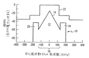
図面を参照して、図1は、本発明によるハイブリッドFM IBOC DAB信号10の周波数割当て(スペクトル配置)及び信号成分の相対的電力スペクトル密度を示す概略図である。ハイブリッド方式は、電力スペクトル密度がチャンネルの中心周波数帯域部分16に位置する三角形14により表される従来型FMステレオアナログ信号12を含む。典型的なアナログFM放送信号の電力スペクトル密度(PSD)はほぼ三角形であり、中心周波数からの勾配は約−0.35dB/kHzである。複数の等間隔デジタル変調サブキャリアは、アナログFM信号の両側の上側波帯18と下側波帯20とに位置し、それらはアナログFM信号と同時に送信される。全てのキャリアは、米国連邦通信委員会のチャンネルマスク22内に収まる電力レベルで送信される。図1の垂直軸は、普通の平均電力スペクトル密度でなくてピーク電力スペクトル密度である。
【0009】
提案されている変調フォーマットの1つは、複数の等間隔直交周波数分割多重化(OFDM)サブキャリアが、ホストアナログFM信号の両側に位置して、図1の上側波帯18及び下側波帯20で示すようなホストFM中心周波数から約129kHz乃至約199kHz離れたスペクトル領域を占有するものである。このハイブリッド方式では、各側波帯におけるOFDM変調サブキャリアの全DAB電力は、ホストアナログFM電力に対して約−25dBに設定されている。DAB信号は、アナログスペクトルの両側に位置するOFDMサブキャリア上で送信される。DABシステムは、ホストFMスペクトルの上方の191個のキャリアと、下方の191個のキャリアを含む。各DABサブキャリアは、344.53125Hzの記号レートでQPSK変調される。同相及び直交成分パルスの形状は、root raised cosine特性を得るためにエッジがテーパーしたもの(過剰時間=7/128)である。このパルス形状により、直交サブキャリア周波数成分の間隔が363.3728Hzとなる。
【0010】
ハイブリッド信号のデジタル変調部分は、全デジタルIBOC DABフォーマットで送信される全デジタルDAB信号の副集合である。図2は、24で示す提案された全デジタルFM DABフォーマットのOFDMデジタルサブキャリアのスペクトル配置及び相対的信号電力密度レベルを示す。図1のアナログFM信号は、中心周波数帯28にある、拡張全デジタル信号28と呼ばれる、オプションとしての別の群のOFDMサブキャリアが置き換わっている。再言するが、等間隔のOFDMサブキャリアが、上側波帯30と下側波帯32とに位置する。図2の全デジタルフォーマットの側波帯は、図1の側波帯よりも幅が広い。さらに、全デジタルIBOC信号の側波帯の電力スペクトル密度レベルは、ハイブリッドIBOC側波帯で許容されるよりも約10dB高く設定されている。これは、全デジタルIBOC信号に有意な性能上の利点を提供する。さらに、拡張全デジタル信号の電力スペクトル密度は、ハイブリッドIBOCの側波帯よりも約15dB低い。このため、隣接するハイブリッドまたは全デジタルIBOC信号に対する干渉の問題が最小限に抑制または解消されると共に他のデジタルサービスを行うための新しい能力が得られる。
【0011】
全デジタルモードは、以前は中央の±100kHz領域を占有していたアナログ信号が低レベルのデジタルサブキャリアに置き換えられるハイブリッドモードの論理的帰結である。低レベルキャリアの両側には2つのデジタル側波帯が存在するが、これらのデジタル側波帯は、帯域幅が約100kHzに増加し、電力が約10dB増加しているためにハイブリッドモードとは異なるものである。提案されている全デジタルDABシステムは、各側波帯に267個のキャリアと、中央に559個のキャリアを含む。各DABサブキャリアは、QPSK変調される。同相及び直交成分パルスの形状は、root raised cosine特性を得るためにエッジがテーパーしたもの(過剰時間=7/128)である。このパルス形状により、直交サブキャリアの周波数間隔が363.3728Hzとなる。送信信号の電力スペクトル密度の軌跡は、全デジタルFM IBOCのマスク内に十分に収まるようにする必要がある。
【0012】
図3は、IBOC DAB FM送信機における本発明の実施態様を説明する機能ブロック図である。記号発生器34は、送信すべき情報を含んだ直交成分シフトキーイング(QPSK)データ記号を発生する。これらの記号は変調器36へ送られ、そこで複数のOFDMサブキャリアが変調されて、DAB信号(規準化済み)が得られる。この変調は、データ記号を逆高速フーリエ変換(IFFT)に通すものであり、QFDM変調が行われる。root raised cosineウィンドウと共に巡回プレフィックスが変調信号に適用される(過剰時間=7/128)。IFFTとウィンドウ適用動作の組み合わせたものを、以下において、DAB変調器と呼ぶ。
【0013】
ブロック38は、ピーク対平均電力比の減少を実現する主要ブロックである。DAB変調器36の変調出力は、このブロックの入力へ送られる。ブロック38の出力は、PARが減少した送信信号である。このPARを減少するために、変調信号はブロック40に示すように振幅制限を受けた後、ブロック42において復調され、復調器から得られる記号ベクトルが、ブロック44において、同相及び直交成分が最小になるようにプレディストーションまたは制約を課せられる。制約を課せられた記号はその後、ブロック46において変調され、その結果得られる第2の変調信号が、ブロック48において、さらに振幅制限を受ける。この振幅制限により、望ましくない相互変調積が生じる。制限された第2の変調信号の相互変調積は、ブロック50において、高電力増幅器52へ送られてアンテナ54から放送される前に、減少または消滅する。
【0014】
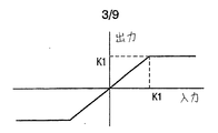
図4は、ブロック40の機能実現のために利用可能なリミターの動作を示す。このリミターは、ある特定のしきい値、または制限値K1に設定されている。入力信号の電力は、任意の瞬間でK1を超えると、K1にクリッピングされる。入力信号は規準化されるため、リミターの出力の信号のPARは必ずK1となる。従って、リミターの動作(実数xに対する)は、以下のように説明できる。入力信号(X)の値が−K1より小さい場合、リミターの出力は−K1に等しく設定され、入力(X)の値がK1より大きい場合、リミターの出力はK1に等しく設定され、また入力信号が−K1とK1の間にある場合、出力信号はその入力信号に等しい。K1が1.58ということは、ピークと平均の比がこの動作で4dBに設定されていることを意味する。
【0015】
制限された変調信号はその後、DAB復調器42へ送られる。このDAB復調器では、変調サンプルに対して最初に、逆巡回プレフィックス・ウィンドウ適用動作が行われる。その後、高速フーリエ変換(FFT)が施されて、OFDM復調が行われる。ウィンドウ適用動作とFFTの組合わせを、以下において、DAB復調器と呼ぶ。
【0016】
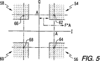
次に、復調ステップにおいて復元されたデータ記号ベクトルの記号点が、その同相及び直交成分が最小となるように制約を課されるため、リミターのクリッピングにより導入されたひずみが減少する。この制約を課すために、各OFDM記号ベクトルは、このステップにおいて、記号点の周りの、図5に示すようなある特定の領域54、56、58または60内に存在するように強制される。図5において、記号点62、64、66及び68は、予想される同相及び直交成分の大きさ「A」を有する。「F」として示す、「A」のある所定の部分は、データ記号が制約を課される領域を画定する。従って、OFDM記号ベクトルの各要素に制約を課す動作を、以下において説明する。
【0017】
記号ベクトル(x)がX=a+b*i(「a」は同相成分、「b」は直交成分)である場合、出力(y)はy=a’+b’*iと定義され、a’とb’は以下のように定義される。
【0018】
【数1】

このような制約により、記号の記号点の同相及び直交成分は、少なくとも、予想させる同相及び直交成分の大きさのある所定の部分に等しい最小値を有するように強制される。
【0020】
次に、制約を課された記号ベクトルはDAB変調器46による変調を受け、変調出力がリミター48へ送られる。リミター48は図4のものと同じ制限機能を利用するが、そのしきい値はK2である。このため、リミター48の出力の信号は、入力信号が規準化されているため、PARがK2となる。
【0021】
送信信号は、ハイブリッドFM IBOCマスク内に十分収まるように、ブロック50においてその非データサブキャリアを0にすることによりクリーンナップする。クリーンナップにより導入されるひずみは、僅かなものである。FM IBOC DABシステムの好ましい実施例では、実際のプロセスは、全ての非作動チャンネル(2つのサイドローブの外側)の非データサブキャリアをクリッピングして0にすることより成る。
【0022】
図6は、本発明のPAR減少方法を説明するフローチャートである。ブロック70は、サブキャリアデータのDAB入力OFDM記号ベクトルがDAB変調器72へ入力されることを示す。その結果ライン74上に得られる第1の変調信号は、ブロック76において、第1のしきい値K1を用いて制限される。これにより、ライン78上に制限された第1の変調信号が発生するが、この信号は、ブロック80において、復調されて、ライン82上にデータ記号ベクトルの記号点が復元される。復元された記号点は、ブロック84において、上述したように同相及び直交成分が所定の最小値を有する制約を課すプレディストーションを施される。DAB変調器86は、制約を課された記号ベクトルを変調して、ライン88上に第2の変調信号を発生させる。この第2の変調信号は、第2のしきい値K2を有するリミター90により制限される。
【0023】
制限動作により相互変調積が発生するため、これらの積を以下のステップで減少させる。ライン92上の第2の制限された変調信号は、ブロック94において復調器へ送られる。ライン96上の復調出力は、ブロック98においてクリーンナップステップへ送られ、そこで非データサブキャリアがクリッピングされて0になる。その結果ライン100上に得られる信号は、ブロック102において変調され、ライン104上の第3の変調信号は、ブロック106において、別の限界しきい値(K3)を用いて制限される。本発明の好ましい実施例では、ブロック94、98、102、106のステップが、最初の繰り返しで、リミター106のしきい値K4を用いて2回繰り返される。第2の繰り返しでは、リミター106は使用されないが、信号はライン108上を高電力増幅器へ送られ放送される。
【0024】
シミュレーションのため、2つのモデルをHPAとして使用した。モデル1は図4に示すような「Z曲線」制限関数を用いる。リミターは、ある特定のしきい値K5に設定されている。信号電力が、任意の瞬間でK5(規準化された入力信号について)を超えると、K5にクリッピングされる。モデル2は、「S曲線」制限関数を用いる。この場合、スケーリングされたエラー関数110により、HPAのモデリングを行う(図7に示すように)。動作点は、K5により設定される。K5が6dBであるということは、信号のRMS値が1dBの圧縮点より6dB低いことを意味する。
【0025】
図8は、サンプルとしてのデジタル音声放送信号におけるOFDMサブキャリアの電力スペクトル密度を、K1=3;K2、K3及びK4=4;F=7/8の制限値を用い、図4のリミターを使用し、種々の最終的なクリッピング基準を用いてシミュレーションした結果を示すグラフである。ライン112で示す信号は、5.5+0.85dBでのクリッピングを表わす。ライン114は5.0+0.85dBのクリッピングを示し、ライン116は4.5+0.86dBでのクリッピング、ライン118は4.0+0.88dBでのクリッピングの結果を示す。図9は、これらのシナリオでのビットエラーレートを、対応する結果のプライム記号を用いて示すものである。ライン119は、クリッピングされない結果を表わす。
【0026】
図10は、サンプルとしてのデジタル音声放送信号におけるOFDMサブキャリアの電力スペクトル密度を、K1=3;K2、K3及びK4=4;F=7/8の制限値を用い、PAR減少方法における図4のリミターと、送信機の出力の高電力増幅器のための図7のリミターとを用いてシミュレーションした結果を示すグラフである。クリッピングされない信号を、ライン120で示す。ライン122は、5.17+1.09sigrms=−8でのクリッピングを示す。図11は、これらのシナリオでの対応ビットエラーレートを、対応する結果のプライム符号を用いて示すものである。
【0027】
図12は、全デジタル信号に対する本発明のPAR減少方法を説明するフローチャートである。ブロック124は、サブキャリアのDAB入力OFDM記号ベクトルがDAB変調器126へ入力されることを示す。その結果、ライン128上に得られる第1の変調信号は、ブロック130において、第1のしきい値K1を用いて制限され、これにより、ライン132上に制限された第1の変調信号が発生する。この変調信号は、ブロック134において復調され、ライン136上にデータ記号ベクトルの記号点が復元される。復元された記号点は、ブロック138において、上述したように同相成分及び直交成分が所定の最小値を有する制約を課すプレディストーションを施される。加えて、望ましくない非データサブキャリアは、このステップにおいて、0にクリッピングされる。DAB変調器140は、制約を課せられた記号ベクトルを変調し、ライン142上に第2の変調信号を発生させる。この第2の変調信号は、第2のしきい値K2を有するリミター144において制限される。
【0028】
制限動作により相互変調積が発生するため、これらの積は、以下のステップにおいて減少される。ライン146上の第2の制限された変調信号は、ブロック148において、復調器へ送られる。ライン150上の復調出力は、ブロック152へ送られ、そこで中央キャリアからのデータ記号がプレディストーションを施されて、非データサブキャリアが0にクリッピングされる。その結果ライン154上に得られる信号は、ブロック156において変調され、ライン158上の第3の変調信号は、ブロック160において、別の制限しきい値(K3)により制限される。本発明の好ましい実施例において、ブロック148、152、156、160のステップは、第1の繰り返しでは、リミター160のしきい値K4を用いて2回繰り返される。第2の繰り返しでは、リミター160は使用されないが、信号は、ライン162上を高電力増幅器へ送られ放送される。
【0029】
図13は、サンプルとしてのデジタル音声放送信号におけるOFDMサブキャリアの電力スペクトル密度を、K1=3;K2、K3及びK4=4;F=7/8の制限値を用い、図4のリミターを使用し、種々の最終的なクリッピング基準を用いてシミュレーションした結果を示すグラフである。クリッピングされない信号をライン164で示す。ライン166は、4.5+0.78dBでのクリッピング、ライン168は5.0+0.77dBでのクリッピング、ライン170は5.5+0.77dBでのクリッピングの結果を示す。図14は、これらのシナリオでの対応ビットエラーレートを、対応する結果のプライム記号を用いて示すものである。
【0030】
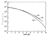
図15は、サンプルとしてのデジタル音声放送信号におけるOFDMサブキャリアの電力スペクトル密度を、K1=3;K2、K3及びK4=4;F=7/8の制限値を用い、PAR減少方法における図4のリミターと、送信機の出力の高電力増幅器のための図7のリミターとを用いてシミュレーションした結果を示すグラフである。クリッピングされない信号を、ライン172で示す。ライン174は、sigrms=6、PAR=6.15+0.95でのクリッピング、ライン176は、sigrms=8、PAR=6.38+0.88でのクリッピングを示す。図16は、これらのシナリオでの対応ビットエラーレートを、対応する結果のプライム符号を用いて示すものである。
【0031】
全てのシミュレーションを、512個のOFDM記号を用いて行った。選択した最適パラメータは、K1=3dB、K2=4dB、K3=4dB、K4=4dB、F=7/8であった。考慮した性能の物差しは、電力スペクトル密度(PSD)と、ビットエラーレート(BER)であった。導入されるひずみを表わすために、復調信号点もプロットした。
【0032】
最後の段階で、サンプリング周波数を、周波数領域において信号を0に加減することにより2倍にすることが可能である。PAR減少方式の複雑さを軽減するために、最後のステップを3回でなくて2回行うことができる。性能が低下するが、PSDは依然としてハイブリッドFM IBOCマスク内にある。
【0033】
本発明は、FM IBOC DABシステムのOFDMのピーク対平均電力比(PAR)を減少させる新規なアプローチである。このアプローチを電力増幅器にZ及びS曲線を用いてシミュレーションした結果、本発明により、PARが4−7dB減少し、依然としてFMマスクの内部に収まることがわかった。プレディストーションにより導入されるひずみは、わずかなものである。特に、パラメータ:K1=3dB、K2=4dB、K3=4dB、K4=4dB、F=7/8を用いることにより、DAB信号について、FMマスクの十分内側の非常に良好なスペクトル占有曲線が得られる。また、この特定セットの値により導入されるひずみはわずかである。
【0034】
本発明は、送信信号のプレディストーションとクリッピングとを組合わせて、送信信号のPARを最小限に抑えるものである。最適化された送信信号でのPARの減少は、シミュレーションの結果により証明されている。本発明を好ましい実施例について説明したが、均等物を含む頭書の特許請求の範囲により定義された本発明の範囲から逸脱することなく、種々の変形例及び設計変更が可能であることを理解されたい。例えば、本発明は、デジタル音声放送への利用に関連して説明したが、マルチキャリア変調によりデジタル情報を送信する他のシステムへも一般的に利用可能である。
【図面の簡単な説明】
【図1】 図1は、ハイブリッドFM IBOC DAB信号の信号成分の相対的電力スペクトル密度及び周波数割当てを表わす概略図である。
【図2】 図2は、全デジタルFM IBOC DAB信号に対する周波数割当て及び信号成分の相対的電力スペクトル密度を表わす概略図である。
【図3】 図3は、本発明のピーク対平均電力比の減少方法を利用できる無線送信機の単純化されたブロック図である。
【図4】 図4は、本発明の方法に使用可能な1つの制限動作を説明するグラフである。
【図5】 図5は、本発明に適用されるデータ記号のプレディストーションを表わす概略図である。
【図6】 図6は、ハイブリッドデジタル音声放送方式に適用される本発明の方法を示すフローチャートである。
【図7】 図7は、本発明の発明に使用可能な別のタイプの制限動作を示すグラフである。
【図8】 図8は、図4の制限関数を用いる本発明により処理された変調波形の電力スペクトル密度をシミュレーションした結果を示すグラフである。
【図9】 図9は、図8に示す種々のシナリオに対するビットエラーレートを示す。
【図10】 図10は、図7の制限関数を高電力増幅器が用いると仮定した場合の本発明により処理された変調波形の電力スペクトル密度のシミュレーション結果を示すグラフである。
【図11】 図11は、図10に示す種々のシナリオに対するビットエラーレートを示す。
【図12】 図12は、全デジタル音声放送送信機に適用される本発明の方法を示すフローチャートである。
【図13】 図13は、図4の制限関数を用いる、本発明により処理される変調波形の電力スペクトル密度をシミュレーションした結果を示すグラフである。
【図14】 図14は、図13に示す種々のシナリオに対するビットエラーレートを示す。
【図15】 図15は、高電力増幅器が図7の制限関数を使用すると仮定した場合の本発明により処理される変調波形の電力スペクトル密度のシミュレーション結果を示すグラフである。
【図16】 図16は、図15に示す種々のシナリオに対するビットエラーレートを示す。[0001]
BACKGROUND OF THE INVENTION
The present invention relates to electronic signal processing, and more particularly to signal processing for reducing the peak-to-average power ratio of radio frequency signals.
[0002]
Digital audio broadcasting (DAB) is a medium that provides audio with digital quality that exceeds existing analog broadcasting systems. FM in-band on channel (IBOC) DAB can be transmitted by either a hybrid system in which a digitally modulated signal coexists with an analog FM signal currently broadcast, or an all-digital system without an analog FM signal. is there. IBOC does not require a new spectrum assignment because each DAB signal is transmitted simultaneously within the same spectrum mask assigned to an existing FM channel. IBOC allows broadcasters to provide digital quality audio to their current listener base while facilitating the economic use of spectrum.
[0003]
Advantages of digitally transmitting audio include that there is less noise and better signal quality than the existing FM radio channel, and that the dynamic range is wide. In the early stages, a hybrid scheme will be employed so that existing receivers can continue to receive analog FM signals and new IBOC receivers can decode digital signals. In the future, when the IBOC DAB receiver becomes widespread, the broadcaster may choose to move to the all-digital system. The goal of FM hybrid IBOC DAB is to transmit existing FM signals while providing stereo CD audio (and data) of virtually CD quality. The goal of FM all-digital IBOC DAB is to provide virtually CD quality stereo audio with a data channel having a capacity of up to about 200 kbps, depending on the interference environment of the particular broadcaster.
[0004]
One proposed FM IBOC broadcast scheme transmits digital signals using multiple orthogonal frequency division multiplexing (OFDM) carriers. An OFDM signal consists of the sum of several carriers modulated at various equally spaced frequencies that are orthogonal to each other. This reliably prevents interference between various subcarriers. There are sometimes very high peaks in the magnitude of the transmitted signal in such systems. Therefore, the linear power amplifier used in the IBOC DAB transmitter must be operated with a large back-off of power so that the out-of-band power is below a predetermined limit value. As a result, the amplifier is expensive and very inefficient. Therefore, there is a need to reduce the peak-to-average power ratio (PAR) of the OFDM DAB signal.
[0005]
The present invention provides a highly efficient method of reducing the peak-to-average power ratio of electronic signals using orthogonal frequency division multiplexing schemes such as those used in FM IBOC DAB systems.
[0006]
SUMMARY OF THE INVENTION
The present invention provides a method for reducing the peak-to-average power ratio of a radio frequency signal. The method modulates a plurality of subcarriers with a plurality of data symbol vectors including a plurality of symbol points having in-phase and quadrature components and representing a data symbol to generate a first modulated signal, Limiting the magnitude of the modulation signal to generate a first limited modulation signal, demodulating the first limited modulation signal to recover the data symbol vector, and converting the in-phase component of each symbol point to the in-phase component Scale to a magnitude greater than or equal to the first predetermined portion of the expected magnitude and the magnitude of the orthogonal component of each symbol point to be greater than or equal to the second predetermined portion of the expected magnitude of the orthogonal component by scaling, the data symbol vectors by performing predistortion to generate a predistorted data symbol vectors, predistortion of a plurality of carriers Generating a second modulated signal by modulating the data symbol vector, generating a second limited modulated signal by limiting the magnitude of the second modulated signal, and generating a second limited modulated signal The step of reducing the intermodulation product.
[0007]
In another embodiment that is particularly applicable to the all-digital IBOC DAB scheme of the present invention, the central subcarrier data symbol vector is further predistorted while simultaneously reducing the intermodulation product of the second limited modulation signal. The
The invention also encompasses a transmitter implementing the above method.
[0008]
[Description of Preferred Embodiment]
Referring to the drawings, FIG. 1 is a schematic diagram illustrating frequency allocation (spectral arrangement) and relative power spectral density of signal components of a hybrid FM
[0009]
One proposed modulation format is that a plurality of equally spaced orthogonal frequency division multiplexing (OFDM) subcarriers are located on either side of the host analog FM signal so that the
[0010]
The digital modulation portion of the hybrid signal is a subset of the all-digital DAB signal transmitted in the all-digital IBOC DAB format. FIG. 2 shows the spectral constellation and relative signal power density level of an OFDM digital subcarrier in the proposed all-digital FM DAB format shown at 24. The analog FM signal of FIG. 1 replaces another optional group of OFDM subcarriers, called extended all-
[0011]
The all-digital mode is a logical consequence of the hybrid mode where analog signals that previously occupied the central ± 100 kHz region are replaced with low-level digital subcarriers. There are two digital sidebands on either side of the low-level carrier, but these digital sidebands differ from the hybrid mode because the bandwidth increases to about 100 kHz and the power increases by about 10 dB. Is. The proposed all-digital DAB system includes 267 carriers in each sideband and 559 carriers in the middle. Each DAB subcarrier is QPSK modulated. The in-phase and quadrature component pulses have a tapered edge (excess time = 7/128) in order to obtain root raised cosine characteristics. With this pulse shape, the frequency interval of orthogonal subcarriers is 363.3728 Hz. The power spectral density trajectory of the transmitted signal needs to be well within the mask of all digital FM IBOC.
[0012]
FIG. 3 is a functional block diagram illustrating an embodiment of the present invention in an IBOC DAB FM transmitter. Symbol generator 34 generates orthogonal component shift keying (QPSK) data symbols that contain the information to be transmitted. These symbols are sent to a modulator 36 where a plurality of OFDM subcarriers are modulated to obtain a DAB signal (normalized). In this modulation, data symbols are passed through inverse fast Fourier transform (IFFT), and QFDM modulation is performed. A cyclic prefix is applied to the modulated signal with a root raised cosine window (excess time = 7/128). A combination of the IFFT and the window application operation is hereinafter referred to as a DAB modulator.
[0013]
[0014]
FIG. 4 shows the operation of the limiter that can be used to realize the function of the
[0015]
The limited modulated signal is then sent to the
[0016]
The symbol points of the data symbol vector restored in the demodulation step are then constrained to minimize their in-phase and quadrature components, thereby reducing distortion introduced by limiter clipping. To impose this constraint, each OFDM symbol vector is forced to exist in this step within a
[0017]
When the symbol vector (x) is X = a + b * i (“a” is an in-phase component and “b” is a quadrature component), the output (y) is defined as y = a ′ + b ′ * i, and a ′ and b ′ is defined as follows.
[0018]
[Expression 1]
Such a constraint forces the in-phase and quadrature components of the symbol point of the symbol to have a minimum value that is at least equal to a predetermined portion of the magnitude of the expected in-phase and quadrature components.
[0020]
The constrained symbol vector is then modulated by the
[0021]
The transmitted signal is cleaned up by zeroing its non-data subcarriers at
[0022]
FIG. 6 is a flowchart for explaining the PAR reduction method of the present invention.
[0023]
Since the intermodulation products are generated by the limiting operation, these products are reduced in the following steps. The second limited modulated signal on
[0024]
Two models were used as HPAs for simulation.
[0025]
FIG. 8 shows the power spectral density of OFDM subcarriers in a digital audio broadcast signal as a sample, using the limiter of FIG. 4 using the limit values of K1 = 3; K2, K3 and K4 = 4; F = 7/8. FIG. 6 is a graph showing the results of simulation using various final clipping criteria. The signal represented by
[0026]
FIG. 10 shows the power spectral density of OFDM subcarriers in a digital audio broadcast signal as a sample using the limit values of K1 = 3; K2, K3 and K4 = 4; F = 7/8, and FIG. 8 is a graph showing the result of simulation using the limiter of FIG. 7 and the limiter of FIG. 7 for the high power amplifier at the output of the transmitter. The signal that is not clipped is indicated by
[0027]
FIG. 12 is a flowchart illustrating the PAR reduction method of the present invention for all digital signals.
[0028]
Since the intermodulation products are generated by the limiting operation, these products are reduced in the following steps. The second limited modulated signal on
[0029]
FIG. 13 shows the power spectral density of OFDM subcarriers in a digital audio broadcast signal as a sample, using the limiter of FIG. 4 using the limit values of K1 = 3; K2, K3 and K4 = 4; F = 7/8. FIG. 6 is a graph showing the results of simulation using various final clipping criteria. The signal that is not clipped is indicated by
[0030]
FIG. 15 shows the power spectral density of OFDM subcarriers in a digital audio broadcast signal as a sample using the limit values of K1 = 3; K2, K3 and K4 = 4; F = 7/8, and FIG. 8 is a graph showing the result of simulation using the limiter of FIG. 7 and the limiter of FIG. 7 for the high power amplifier at the output of the transmitter. The signal that is not clipped is indicated by
[0031]
All simulations were performed using 512 OFDM symbols. The optimum parameters selected were K1 = 3 dB, K2 = 4 dB, K3 = 4 dB, K4 = 4 dB, F = 7/8. The performance metrics considered were power spectral density (PSD) and bit error rate (BER). The demodulated signal points are also plotted to represent the distortion introduced.
[0032]
At the last stage, the sampling frequency can be doubled by adding or subtracting the signal to zero in the frequency domain. To reduce the complexity of the PAR reduction scheme, the last step can be performed twice instead of three times. Although performance is degraded, PSD is still in the hybrid FM IBOC mask.
[0033]
The present invention is a novel approach for reducing the OFDM peak-to-average power ratio (PAR) of FM IBOC DAB systems. As a result of simulating this approach with Z and S curves for power amplifiers, it was found that the present invention reduced the PAR by 4-7 dB and still fit within the FM mask. The strain introduced by predistortion is negligible. In particular, by using the parameters: K1 = 3 dB, K2 = 4 dB, K3 = 4 dB, K4 = 4 dB, F = 7/8, a very good spectral occupancy curve well inside the FM mask is obtained for the DAB signal. . Also, the distortion introduced by this particular set of values is negligible.
[0034]
The present invention combines transmission signal predistortion and clipping to minimize the PAR of the transmission signal. The reduction of PAR with the optimized transmission signal is proved by simulation results. While the invention has been described in terms of a preferred embodiment, it will be understood that various modifications and design changes may be made without departing from the scope of the invention as defined by the appended claims, including equivalents. I want. For example, although the present invention has been described in connection with its use for digital audio broadcasting, it is generally applicable to other systems that transmit digital information by multi-carrier modulation.
[Brief description of the drawings]
FIG. 1 is a schematic diagram representing the relative power spectral density and frequency assignment of signal components of a hybrid FM IBOC DAB signal.
FIG. 2 is a schematic diagram representing frequency assignment and relative power spectral density of signal components for an all digital FM IBOC DAB signal.
FIG. 3 is a simplified block diagram of a wireless transmitter that can utilize the peak-to-average power ratio reduction method of the present invention.
FIG. 4 is a graph illustrating one limiting action that can be used in the method of the present invention.
FIG. 5 is a schematic diagram showing predistortion of data symbols applied to the present invention.
FIG. 6 is a flowchart showing a method of the present invention applied to a hybrid digital audio broadcasting system.
FIG. 7 is a graph showing another type of limiting action that can be used in the invention of the present invention.
FIG. 8 is a graph showing the result of simulating the power spectral density of a modulated waveform processed according to the present invention using the limiting function of FIG. 4;
FIG. 9 shows bit error rates for the various scenarios shown in FIG.
FIG. 10 is a graph showing simulation results of power spectral density of a modulated waveform processed according to the present invention when it is assumed that a high power amplifier uses the limiting function of FIG.
FIG. 11 shows bit error rates for the various scenarios shown in FIG.
FIG. 12 is a flowchart showing the method of the present invention applied to an all-digital audio broadcast transmitter.
FIG. 13 is a graph showing the result of simulating the power spectral density of the modulation waveform processed by the present invention using the limiting function of FIG. 4;
FIG. 14 shows bit error rates for the various scenarios shown in FIG.
FIG. 15 is a graph showing simulation results of the power spectral density of the modulated waveform processed by the present invention assuming that the high power amplifier uses the limiting function of FIG.
FIG. 16 shows bit error rates for the various scenarios shown in FIG.
Claims (8)
複数のサブキャリアを、同相成分及び直交成分を有しデータ記号を表わす複数の記号点を含んだ複数のデータ記号ベクトルで変調して第1の変調信号を発生させ、
第1の変調信号の大きさを制限して第1の制限された変調信号を発生させ、
第1の制限された変調信号を復調してデータ記号ベクトルを復元し、
各記号点の同相成分を同相成分の予想させる大きさの第1の所定の部分より大きいかそれに等しい大きさにスケーリングし、各記号点の直交成分を直交成分の予想させる大きさの第2の所定の部分より大きいかそれに等しい大きさにスケーリングすることにより、データ記号ベクトルにプレディストーションを施してプレディストーションされたデータ記号ベクトルを発生させ、
複数のキャリアをプレディストーションされたデータ記号ベクトルで変調して第2の変調信号を発生させ、
第2の変調信号の大きさを制限して第2の制限された変調信号を発生させ、
第2の制限された変調信号の相互変調積を減少させるステップより成る無線周波数信号のピーク対平均電力比の減少方法。A method for reducing the peak-to-average power ratio of a radio frequency signal, comprising:
Modulating a plurality of subcarriers with a plurality of data symbol vectors having a plurality of symbol points having in-phase and quadrature components and representing data symbols, to generate a first modulated signal;
Generating a first limited modulated signal by limiting the magnitude of the first modulated signal;
Demodulating the first limited modulated signal to recover the data symbol vector;
The in-phase component of each symbol point is scaled to a magnitude greater than or equal to a first predetermined portion of the expected magnitude of the in-phase component, and the quadrature component of each symbol point is a second magnitude of the expected magnitude of the quadrature component. Predistorting the data symbol vector to generate a predistorted data symbol vector by scaling to a size greater than or equal to the predetermined portion ;
Modulating a plurality of carriers with a predistorted data symbol vector to generate a second modulated signal;
Generating a second limited modulated signal by limiting the magnitude of the second modulated signal;
A method for reducing the peak-to-average power ratio of a radio frequency signal comprising the step of reducing the intermodulation product of a second limited modulation signal.
第2の変調信号を復調して第2の復調信号を発生させ、
第2の復調信号中の非データサブキャリアを0にクリッピングし、
第2の復調信号を変調して第3の変調信号を発生させるステップより成る請求項1の方法。Reducing the intermodulation product of the second limited modulation signal comprises:
Demodulating the second modulated signal to generate a second demodulated signal;
Clipping non-data subcarriers in the second demodulated signal to 0;
The method of claim 1, comprising the step of modulating the second demodulated signal to generate a third modulated signal.
第1の変調信号の最大の大きさを所定の一定値に設定するステップより成る請求項1の方法。Limiting the magnitude of the first modulation signal to generate the first limited modulation signal comprises:
2. The method of claim 1 comprising the step of setting the maximum magnitude of the first modulated signal to a predetermined constant value.
、
第1の変調信号の最大の大きさをスケーリングされたZ曲線により決定される所定の大きさに設定するステップより成る請求項1の方法。Limiting the magnitude of the first modulation signal to generate the first limited modulation signal comprises:
2. The method of claim 1 comprising the step of setting the maximum magnitude of the first modulated signal to a predetermined magnitude determined by a scaled Z curve.
第1群はラジオチャンネルの上及び下側波帯にあり、第2群はラジオチャンネルの中央帯にある複数のサブキャリアを、同相成分及び直交成分を有しデータ記号を表わす複数の記号点を含んだ複数のデータ記号ベクトルで変調して第1の変調信号を発生させ、
第1の変調信号の大きさを制限して第1の制限された変調信号を発生させ、
第1の制限された変調信号の相互変調積を除去し、
第1の制限された変調信号を復調して記号点を復元し、
各記号点の同相成分を同相成分の予想させる大きさの第1の所定の部分より大きいかそれに等しい大きさにスケーリングし、各記号点の直交成分を直交成分の予想させる大きさの第2の所定の部分より大きいかそれに等しい大きさにスケーリングすることにより、第1の群のサブキャリアのデータ記号ベクトルにプレディストーションを施してプレディストーションされたデータ記号を発生させ、
複数のキャリアをプレディストーションされたデータ記号ベクトルで変調して第2の変調信号を発生させ、
第2の変調信号の大きさを制限して第2の制限された変調信号を発生させ、
第2の制限された変調信号の相互変調積を除去し、
各記号点の同相成分を同相成分の予想させる大きさの第1の所定の部分より大きいかそれに等しい大きさにスケーリングし、各記号点の直交成分を直交成分の予想させる大きさの第2の所定の部分より大きいかそれに等しい大きさにスケーリングすることにより、第2群のサブキャリアのデータ記号ベクトルにプレディストーションを施して別のプレディストーションされたデータ記号ベクトルを発生させるステップより成る無線周波数信号のピーク対平均電力比減少方法。A method for reducing the peak-to-average power ratio of a radio frequency signal, comprising:
The first group is in the upper and lower sidebands of the radio channel, the second group is a plurality of subcarriers in the center band of the radio channel, and a plurality of symbol points having in-phase and quadrature components and representing data symbols. Modulating a plurality of contained data symbol vectors to generate a first modulated signal;
Generating a first limited modulated signal by limiting the magnitude of the first modulated signal;
Removing the intermodulation product of the first limited modulation signal;
Demodulating the first limited modulated signal to recover the symbol points ;
The in-phase component of each symbol point is scaled to a magnitude greater than or equal to a first predetermined portion of the expected magnitude of the in-phase component, and the quadrature component of each symbol point is a second magnitude of the expected magnitude of the quadrature component. Predistorting the data symbol vectors of the first group of subcarriers by scaling to a magnitude greater than or equal to the predetermined portion to generate predistorted data symbols;
Modulating a plurality of carriers with a predistorted data symbol vector to generate a second modulated signal;
Generating a second limited modulated signal by limiting the magnitude of the second modulated signal;
Removing the intermodulation product of the second limited modulation signal;
The in-phase component of each symbol point is scaled to a magnitude greater than or equal to a first predetermined portion of the expected magnitude of the in-phase component, and the quadrature component of each symbol point is a second magnitude of the expected magnitude of the quadrature component. A radio frequency signal comprising the step of predistorting the data symbol vectors of the second group of subcarriers to generate another predistorted data symbol vector by scaling to a magnitude greater than or equal to a predetermined portion To reduce the peak-to-average power ratio.
複数のサブキャリアを、同相成分及び直交成分を有しデータ記号を表わす複数の記号点を含んだ複数のデータ記号ベクトルで変調して第1の変調信号を発生させる手段と、
第1の変調信号の大きさを制限して第1の制限された変調信号を発生させる手段と、
第1の制限された変調信号を復調してデータ記号ベクトルを復元する手段と、
各記号点の同相成分を同相成分の予想させる大きさの第1の所定の部分より大きいかそれに等しい大きさにスケーリングし、各記号点の直交成分を直交成分の予想させる大きさの第2の所定の部分より大きいかそれに等しい大きさにスケーリングすることにより、データ記号ベクトルにプレディストーションを施してプレディストーションされたデータ記号ベクトルを発生させる手段と、
複数のキャリアをプレディストーションされたデータ記号ベクトルで変調して第2の変調信号を発生させる手段と、
第2の変調信号の大きさを制限して第2の制限された変調信号を発生させる手段と、
第2の制限された変調信号の相互変調積を減少させる手段とより成る無線周波数送信機。A radio frequency transmitter that provides a radio frequency signal with reduced peak-to-average power ratio,
Means for modulating a plurality of subcarriers with a plurality of data symbol vectors including a plurality of symbol points having in- phase and quadrature components and representing data symbols to generate a first modulated signal;
Means for generating a first limited modulated signal by limiting the magnitude of the first modulated signal;
Means for demodulating the first limited modulated signal to recover the data symbol vector;
The in-phase component of each symbol point is scaled to a magnitude greater than or equal to a first predetermined portion of the expected magnitude of the in-phase component, and the quadrature component of each symbol point is a second magnitude of the expected magnitude of the quadrature component. Means for predistorting the data symbol vector to generate a predistorted data symbol vector by scaling to a size greater than or equal to the predetermined portion ;
Means for modulating a plurality of carriers with a predistorted data symbol vector to generate a second modulated signal;
Means for limiting the magnitude of the second modulation signal to generate a second limited modulation signal;
A radio frequency transmitter comprising means for reducing the intermodulation product of the second limited modulation signal.
第1群はラジオチャンネルの上及び下側波帯にあり、第2群はラジオチャンネルの中央帯にある複数のサブキャリアを、同相成分及び直交成分を有しデータ記号を表わす複数の記号点を含んだ複数のデータ記号ベクトルで変調して第1の変調信号を発生させる手段と、
第1の変調信号の大きさを制限して第1の制限された変調信号を発生させ、第1の制限された変調信号の相互変調積を除去する手段と、
第1の制限された変調信号を復調して記号点を復元する手段と、
各記号点の同相成分を同相成分の予想させる大きさの第1の所定の部分より大きいかそれに等しい大きさにスケーリングし、各記号点の直交成分を直交成分の予想させる大きさの第2の所定の部分より大きいかそれに等しい大きさにスケーリングすることにより、第1の群のサブキャリアのデータ記号ベクトルにプレディストーションを施してプレディストーションされたデータ記号を発生させる手段と、
複数のキャリアをプレディストーションされたデータ記号ベクトルで変調して第2の変調信号を発生させる手段と、
第2の変調信号の大きさを制限して第2の制限された変調信号を発生させる手段と、
第2の制限された変調信号の相互変調積を除去する手段と、
各記号点の同相成分を同相成分の予想させる大きさの第1の所定の部分より大きいかそれに等しい大きさにスケーリングし、各記号点の直交成分を直交成分の予想させる大きさの第2の所定の部分より大きいかそれに等しい大きさにスケーリングすることにより、第2群のサブキャリアのデータ記号ベクトルにプレディストーションを施して別のプレディストーションされたデータ記号ベクトルを発生させる手段とより成る無線周波数送信機。A radio frequency transmitter that provides a radio frequency signal with reduced peak-to-average power ratio,
The first group is in the upper and lower sidebands of the radio channel, the second group is a plurality of subcarriers in the center band of the radio channel, and a plurality of symbol points having in-phase and quadrature components and representing data symbols. It means for generating a first modulated signal by modulating a plurality of data symbol vectors containing,
Means for limiting the magnitude of the first modulated signal to generate a first limited modulated signal and removing an intermodulation product of the first limited modulated signal;
Means for demodulating the first limited modulation signal to restore the symbol points ;
The in-phase component of each symbol point is scaled to a magnitude greater than or equal to a first predetermined portion of the expected magnitude of the in-phase component, and the quadrature component of each symbol point is a second magnitude of the expected magnitude of the quadrature component. Means for predistorting the data symbol vectors of the first group of subcarriers by scaling to a magnitude greater than or equal to the predetermined portion to generate predistorted data symbols;
Means for modulating a plurality of carriers with a predistorted data symbol vector to generate a second modulated signal;
Means for limiting the magnitude of the second modulation signal to generate a second limited modulation signal;
Means for removing the intermodulation product of the second limited modulation signal;
The in-phase component of each symbol point is scaled to a magnitude greater than or equal to a first predetermined portion of the expected magnitude of the in-phase component, and the quadrature component of each symbol point is a second magnitude of the expected magnitude of the quadrature component. Radio frequency comprising means for predistorting the data symbol vectors of the second group of subcarriers by scaling to a magnitude greater than or equal to a predetermined portion to generate another predistorted data symbol vector Transmitter.
Applications Claiming Priority (3)
| Application Number | Priority Date | Filing Date | Title |
|---|---|---|---|
| US09/379,780 | 1999-08-24 | ||
| US09/379,780 US6128350A (en) | 1999-08-24 | 1999-08-24 | Method and apparatus for reducing peak to average power ratio in digital broadcasting systems |
| PCT/US2000/023184 WO2001015402A1 (en) | 1999-08-24 | 2000-08-23 | Method and apparatus for reducing peak to average power ratio in digital broadcasting systems |
Publications (3)
| Publication Number | Publication Date |
|---|---|
| JP2003507968A JP2003507968A (en) | 2003-02-25 |
| JP2003507968A5 JP2003507968A5 (en) | 2007-08-09 |
| JP4574095B2 true JP4574095B2 (en) | 2010-11-04 |
Family
ID=23498656
Family Applications (1)
| Application Number | Title | Priority Date | Filing Date |
|---|---|---|---|
| JP2001519004A Expired - Lifetime JP4574095B2 (en) | 1999-08-24 | 2000-08-23 | Method and apparatus for reducing peak-to-average power ratio in a digital broadcasting system |
Country Status (15)
| Country | Link |
|---|---|
| US (1) | US6128350A (en) |
| EP (1) | EP1206866B1 (en) |
| JP (1) | JP4574095B2 (en) |
| KR (1) | KR100623830B1 (en) |
| CN (1) | CN1205793C (en) |
| AR (1) | AR027843A1 (en) |
| AT (1) | ATE308187T1 (en) |
| AU (1) | AU765568B2 (en) |
| BR (1) | BR0013532B1 (en) |
| CA (1) | CA2385125C (en) |
| DE (1) | DE60023513T2 (en) |
| MX (1) | MXPA02001364A (en) |
| RU (1) | RU2234199C2 (en) |
| TW (1) | TW519804B (en) |
| WO (1) | WO2001015402A1 (en) |
Families Citing this family (81)
| Publication number | Priority date | Publication date | Assignee | Title |
|---|---|---|---|---|
| DE19808993C2 (en) * | 1998-03-03 | 2003-12-18 | Fraunhofer Ges Forschung | Process for peak value reduction in single-carrier-modulated or multi-carrier-modulated, digital transmission signals |
| US6556557B1 (en) | 1999-06-02 | 2003-04-29 | At&T Corp. | Method and system for reducing of peak-to-average power ratio of transmission signals comprising overlapping waveforms |
| US6961369B1 (en) | 1999-11-09 | 2005-11-01 | Aware, Inc. | System and method for scrambling the phase of the carriers in a multicarrier communications system |
| US6922448B1 (en) * | 1999-11-17 | 2005-07-26 | Texas Instruments Incorporated | Upstream power back-off |
| US7908172B2 (en) | 2000-03-09 | 2011-03-15 | Impulse Radio Inc | System and method for generating multimedia accompaniments to broadcast data |
| WO2003009592A1 (en) | 2001-07-17 | 2003-01-30 | Impulse Radio, Inc. | System and method for transmitting digital multimedia data with analog broadcast data. |
| US7418043B2 (en) * | 2000-07-19 | 2008-08-26 | Lot 41 Acquisition Foundation, Llc | Software adaptable high performance multicarrier transmission protocol |
| EP1302045A2 (en) | 2000-07-21 | 2003-04-16 | PMC-Sierra Ltd. | Reduction of peak to average power ratio |
| US8670390B2 (en) | 2000-11-22 | 2014-03-11 | Genghiscomm Holdings, LLC | Cooperative beam-forming in wireless networks |
| US20020168016A1 (en) * | 2001-03-14 | 2002-11-14 | Xianbin Wang | Method and apparatus for reducing peak to average power ratio in a multi-carrier modulation communication system |
| US7127005B2 (en) * | 2001-03-23 | 2006-10-24 | James Stuart Wight | Computational circuits and methods for processing modulated signals having non-constant envelopes |
| US10931338B2 (en) | 2001-04-26 | 2021-02-23 | Genghiscomm Holdings, LLC | Coordinated multipoint systems |
| US10355720B2 (en) | 2001-04-26 | 2019-07-16 | Genghiscomm Holdings, LLC | Distributed software-defined radio |
| US9819449B2 (en) | 2002-05-14 | 2017-11-14 | Genghiscomm Holdings, LLC | Cooperative subspace demultiplexing in content delivery networks |
| US20030063663A1 (en) * | 2001-10-01 | 2003-04-03 | Bryant Paul Henry | Multistage equalizer that corrects for linear and nonlinear distortion in a digitally-modulated signal |
| US20030067990A1 (en) * | 2001-10-01 | 2003-04-10 | Bryant Paul Henry | Peak to average power ratio reduction in a digitally-modulated signal |
| US8331490B2 (en) * | 2001-10-22 | 2012-12-11 | Panasonic Corporation | Methods and apparatus for conditioning communications signals based on detection of high-frequency events in polar domain |
| US20070211829A1 (en) * | 2001-10-22 | 2007-09-13 | Matsushita Electric Industrial Co., Ltd. | Method and apparatus for pulse optimization for non-linear filtering |
| US7054385B2 (en) * | 2001-10-22 | 2006-05-30 | Tropian, Inc. | Reduction of average-to-minimum power ratio in communications signals |
| FR2832275B1 (en) * | 2001-11-12 | 2004-11-19 | Evolium Sas | PROCESS FOR CLIPPING SIGNALS WITH MULTIPLE CARRIERS TRANSMITTED BY A SAME NON-LINEAR AMPLIFIER |
| US10200227B2 (en) | 2002-05-14 | 2019-02-05 | Genghiscomm Holdings, LLC | Pre-coding in multi-user MIMO |
| US10142082B1 (en) | 2002-05-14 | 2018-11-27 | Genghiscomm Holdings, LLC | Pre-coding in OFDM |
| US9628231B2 (en) | 2002-05-14 | 2017-04-18 | Genghiscomm Holdings, LLC | Spreading and precoding in OFDM |
| US10644916B1 (en) | 2002-05-14 | 2020-05-05 | Genghiscomm Holdings, LLC | Spreading and precoding in OFDM |
| US7260054B2 (en) * | 2002-05-30 | 2007-08-21 | Denso Corporation | SINR measurement method for OFDM communications systems |
| MXPA04002365A (en) | 2002-06-21 | 2004-11-22 | Lg Electronics Inc | Recording medium having data structure for managing reproduction of video data recorded thereon. |
| JP4299779B2 (en) | 2002-06-21 | 2009-07-22 | エルジー エレクトロニクス インコーポレーテッド | Recording medium having data structure for managing reproduction of video data |
| KR20040000290A (en) | 2002-06-24 | 2004-01-03 | 엘지전자 주식회사 | Method for managing multi-path data stream of high density optical disc |
| CN101350215B (en) | 2002-06-24 | 2012-08-29 | Lg电子株式会社 | Method and device for recording and reproducing data structure of reproduction for video data |
| WO2004001752A1 (en) | 2002-06-24 | 2003-12-31 | Lg Electronics Inc. | Recording medium having data structure for managing reproduction of multiple title video data recorded thereon and recording and reproducing methods and apparatuses |
| RU2347284C2 (en) | 2002-10-14 | 2009-02-20 | Эл Джи Электроникс Инк. | Carrier of record with structure of data for guidance of reproduction of set of audio streams written down on it and methods and record and reproduction devices |
| JP4903998B2 (en) | 2002-10-15 | 2012-03-28 | エルジー エレクトロニクス インコーポレイティド | RECORDING MEDIUM HAVING DATA STRUCTURE FOR MANAGING REPRODUCTION OF RECORDED MULTIPLE GRAPHIC STREAMS, RECORDING AND REPRODUCING METHOD AND APPARATUS THEREFOR |
| CN100483967C (en) * | 2002-12-31 | 2009-04-29 | 中国科学技术大学 | Transmitter and receiver capable of controlling peak power |
| US7693394B2 (en) | 2003-02-26 | 2010-04-06 | Lg Electronics Inc. | Recording medium having data structure for managing reproduction of data streams recorded thereon and recording and reproducing methods and apparatuses |
| US7809775B2 (en) | 2003-02-27 | 2010-10-05 | Lg Electronics, Inc. | Recording medium having data structure for managing playback control recorded thereon and recording and reproducing methods and apparatuses |
| CN100397882C (en) | 2003-02-28 | 2008-06-25 | Lg电子株式会社 | Recording medium having data structure for managing random/shuffle reproduction of video data recorded thereon and recording and reproducing methods and apparatuses |
| US7620301B2 (en) | 2003-04-04 | 2009-11-17 | Lg Electronics Inc. | System and method for resuming playback |
| GB2401516A (en) * | 2003-04-17 | 2004-11-10 | Univ Southampton | Peak-to-average power ratio reduction by subtracting shaped pulses from a baseband signal |
| US7103111B2 (en) * | 2003-06-16 | 2006-09-05 | Motorola, Inc. | System and method for generating a spectral efficient root raised cosine (RRC) pulse for increasing spectral efficiency |
| JP2007503734A (en) * | 2003-08-22 | 2007-02-22 | コーニンクレッカ フィリップス エレクトロニクス エヌ ヴィ | Backward compatible multi-carrier transmission system |
| US7542517B2 (en) * | 2004-02-02 | 2009-06-02 | Ibiquity Digital Corporation | Peak-to-average power reduction for FM OFDM transmission |
| WO2005096580A1 (en) * | 2004-03-12 | 2005-10-13 | Ntt Docomo, Inc. | Peak reduction in ofdm using clipping and modified constellations |
| JP4436409B2 (en) * | 2004-03-12 | 2010-03-24 | 株式会社エヌ・ティ・ティ・ドコモ | Peak reduction in OFDM with clipping and modified constellation |
| US8166299B2 (en) | 2004-07-06 | 2012-04-24 | Andrew Christopher Kemshall | Secure messaging |
| US8141118B2 (en) * | 2004-07-26 | 2012-03-20 | Microsoft Corporation | Data broadcasting receiver power management |
| US11552737B1 (en) | 2004-08-02 | 2023-01-10 | Genghiscomm Holdings, LLC | Cooperative MIMO |
| US11381285B1 (en) | 2004-08-02 | 2022-07-05 | Genghiscomm Holdings, LLC | Transmit pre-coding |
| US11184037B1 (en) | 2004-08-02 | 2021-11-23 | Genghiscomm Holdings, LLC | Demodulating and decoding carrier interferometry signals |
| US7474707B2 (en) * | 2004-09-09 | 2009-01-06 | Ibiquity Digital Corporation | Bandwidth reduction of an FM broadcast signal using a baseband precompensation technique |
| CN100364302C (en) * | 2005-01-28 | 2008-01-23 | 北京北广科数字广播电视技术有限公司 | Digital audio frequency processing method for analog amplitude modulation medium wave broadcasting transmitter digital improvement |
| US7653122B2 (en) * | 2005-06-01 | 2010-01-26 | University Of Maryland | Method and system for power controlled effective allocation of sub-bands in ultra-wideband communication |
| US7453953B2 (en) * | 2005-06-01 | 2008-11-18 | Motorola, Inc. | System and method for enlarging amplitude minima in a linear modulation signal |
| US20060291584A1 (en) * | 2005-06-28 | 2006-12-28 | Harris Corporation | Composite crest factor reduction |
| US8280420B2 (en) * | 2006-04-03 | 2012-10-02 | Qualcomm Incorporated | Multi-level saturation |
| US8064537B2 (en) * | 2006-11-03 | 2011-11-22 | Qualcomm Incorporated | Method and apparatus for dynamically adjusting a transmission power spectral density of pilot and data symbols |
| KR100902017B1 (en) * | 2007-12-28 | 2009-06-15 | 포스데이타 주식회사 | Transmitter and method for subcarrier scaling in mobile station of ofdma |
| GB0810855D0 (en) * | 2008-06-13 | 2008-07-23 | Gigle Semiconductors Ltd | Method system and computer program for improving a communication system |
| GB2461904B (en) * | 2008-07-17 | 2011-02-02 | Martin Tomlinson | Handoff communication system for internet radio |
| CN102197621B (en) * | 2008-08-25 | 2016-02-10 | 阿威尔有限公司 | The transmission PSD upper limit in packet-based ofdm system |
| CN102025682B (en) * | 2010-12-24 | 2013-05-01 | 北京邮电大学 | All-optical OFDM (orthogonal frequency division multiplexing) system transmitter device, OFDM system and method for processing signals |
| US8798196B2 (en) | 2011-01-25 | 2014-08-05 | Ibiquity Digital Corporation | Peak-to-average power ratio reduction for hybrid FM HD radio transmission |
| US20130044836A1 (en) * | 2011-08-18 | 2013-02-21 | Vyycore Ltd. | Device and method for pre-distorting and amplifying a signal based on an error attribute |
| US20130113559A1 (en) * | 2011-11-08 | 2013-05-09 | Vyycore Ltd. | Device and method for pre-distorting and amplifying a signal based on an error attribute |
| RU2527478C2 (en) * | 2012-10-03 | 2014-09-10 | Федеральное государственное бюджетное учреждение науки Институт проблем проектирования в микроэлектронике Российской академии наук (ИППМ РАН) | Energy-efficient signal transmitter and receiver in wire link with mode switching device |
| US8948272B2 (en) | 2012-12-03 | 2015-02-03 | Digital PowerRadio, LLC | Joint source-channel decoding with source sequence augmentation |
| US9191256B2 (en) | 2012-12-03 | 2015-11-17 | Digital PowerRadio, LLC | Systems and methods for advanced iterative decoding and channel estimation of concatenated coding systems |
| US8595590B1 (en) | 2012-12-03 | 2013-11-26 | Digital PowerRadio, LLC | Systems and methods for encoding and decoding of check-irregular non-systematic IRA codes |
| US9178740B1 (en) | 2014-08-26 | 2015-11-03 | Ibiquity Digital Corporation | Peak-to-average power ratio reduction for QAM modulation with HD radio signals |
| KR102262735B1 (en) * | 2015-01-27 | 2021-06-09 | 한국전자통신연구원 | Method and Apparatus for Processing Transmission Signal for PAPR Reduction in Time Region |
| CA2887751C (en) | 2015-04-10 | 2023-09-05 | Nautel Limited | Multiplex of high definition radio stations |
| FR3039730B1 (en) * | 2015-07-27 | 2017-07-21 | Thales Sa | REDUCTION OF THE CRETE FACTOR OF A TRANSMISSION PATH OF A SINGLE-CARRIER SIGNAL |
| US10243773B1 (en) | 2017-06-30 | 2019-03-26 | Genghiscomm Holdings, LLC | Efficient peak-to-average-power reduction for OFDM and MIMO-OFDM |
| US10637705B1 (en) | 2017-05-25 | 2020-04-28 | Genghiscomm Holdings, LLC | Peak-to-average-power reduction for OFDM multiple access |
| US11082279B2 (en) | 2018-09-27 | 2021-08-03 | At&T Intellectual Property I, L.P. | Facilitation of reduction of peak to average power ratio for 5G or other next generation network |
| US10659270B2 (en) | 2018-10-10 | 2020-05-19 | At&T Intellectual Property I, L.P. | Mapping reference signals in wireless communication systems to avoid repetition |
| US11418992B2 (en) | 2018-11-02 | 2022-08-16 | At&T Intellectual Property I, L.P. | Generation of demodulation reference signals in advanced networks |
| US11917604B2 (en) | 2019-01-25 | 2024-02-27 | Tybalt, Llc | Orthogonal multiple access and non-orthogonal multiple access |
| US11343823B2 (en) | 2020-08-16 | 2022-05-24 | Tybalt, Llc | Orthogonal multiple access and non-orthogonal multiple access |
| CN113454964A (en) | 2019-01-25 | 2021-09-28 | 珍吉斯科姆控股有限责任公司 | Orthogonal and non-orthogonal multiple access |
| WO2020242898A1 (en) | 2019-05-26 | 2020-12-03 | Genghiscomm Holdings, LLC | Non-orthogonal multiple access |
| CA3070530A1 (en) | 2020-01-30 | 2021-07-30 | Nautel Limited | Iboc compatible superposition modulation by independent modulators utilizing clipping noise from peak-to-average power reduction |
Family Cites Families (26)
| Publication number | Priority date | Publication date | Assignee | Title |
|---|---|---|---|---|
| US4370622A (en) * | 1981-03-23 | 1983-01-25 | Rockwell International Corporation | IMD Limiter |
| JPH03198407A (en) * | 1989-12-26 | 1991-08-29 | Mitsubishi Electric Corp | Linear amplifier |
| US5381449A (en) * | 1990-06-12 | 1995-01-10 | Motorola, Inc. | Peak to average power ratio reduction methodology for QAM communications systems |
| US5201071A (en) * | 1990-09-26 | 1993-04-06 | Rockwell International Corporation | Method and apparatus for reducing the peak envelope voltage of an RF transmitter while maintaining signal average power |
| GB9218874D0 (en) * | 1992-09-07 | 1992-10-21 | British Broadcasting Corp | Improvements relating to the transmission of frequency division multiplex signals |
| US5300894A (en) * | 1992-10-20 | 1994-04-05 | At&T Bell Laboratories | Circuitry for minimizing peak power in an amplifier carrying a plurality of signals of differing frequencies |
| US5302914A (en) * | 1992-10-20 | 1994-04-12 | At&T Bell Laboratories | Method and apparatus for reducing the peak-to-average power in multi-carrier RF communication systems |
| FR2707127A1 (en) * | 1993-06-29 | 1995-01-06 | Philips Laboratoire Electroniq | Digital transmission system with predisposition. |
| JP3420613B2 (en) * | 1993-06-30 | 2003-06-30 | 日本無線株式会社 | Quadrature modulator |
| US5349300A (en) * | 1993-08-10 | 1994-09-20 | Motorola, Inc. | Method and apparatus for controlling a peak envelope power of a PA |
| GB9418514D0 (en) * | 1994-09-14 | 1994-11-02 | At & T Global Inf Solution | Information transmission system |
| US5838732A (en) * | 1994-10-31 | 1998-11-17 | Airnet Communications Corp. | Reducing peak-to-average variance of a composite transmitted signal generated by a digital combiner via carrier phase offset |
| US5835536A (en) * | 1995-02-02 | 1998-11-10 | Motorola, Inc. | Method and apparatus for reducing peak-to-average requirements in multi-tone communication circuits |
| US5621762A (en) * | 1995-06-12 | 1997-04-15 | Motorola, Inc. | Radio with peak power and bandwidth efficient modulation |
| US5606578A (en) * | 1995-06-26 | 1997-02-25 | Motorola, Inc. | Radio with peak power and bandwidth efficient modulation using asymmetric symbol constellations |
| US5727026A (en) * | 1995-11-15 | 1998-03-10 | Motorola, Inc. | Method and apparatus for peak suppression using complex scaling values |
| US5710990A (en) * | 1996-03-21 | 1998-01-20 | Motorola, Inc. | Transmitter which adjusts peak-to-average power of a multicarrier signal by switching between a group of channels and a phase-adjusted group of channels |
| US5796784A (en) * | 1996-03-27 | 1998-08-18 | Motorola, Inc. | Method and apparatus for modifying amplitude of at least one symbol |
| US5696794A (en) * | 1996-04-04 | 1997-12-09 | Motorola, Inc. | Method and apparatus for conditioning digitally modulated signals using channel symbol adjustment |
| US5815532A (en) * | 1996-05-01 | 1998-09-29 | Glenayre Electronics, Inc. | Method and apparatus for peak-to-average ratio control in an amplitude modulation paging transmitter |
| US5949796A (en) * | 1996-06-19 | 1999-09-07 | Kumar; Derek D. | In-band on-channel digital broadcasting method and system |
| US5970053A (en) * | 1996-12-24 | 1999-10-19 | Rdl, Inc. | Method and apparatus for controlling peak factor of coherent frequency-division-multiplexed systems |
| FR2758030B1 (en) * | 1996-12-31 | 1999-03-26 | Sgs Thomson Microelectronics | METHOD AND DEVICE FOR SHAPING A CLIPPING NOISE OF A MULTI-PORTABLE MODULATION |
| US6081158A (en) * | 1997-06-30 | 2000-06-27 | Harris Corporation | Adaptive pre-distortion apparatus for linearizing an amplifier output within a data transmission system |
| US6049707A (en) * | 1997-09-02 | 2000-04-11 | Motorola, Inc. | Broadband multicarrier amplifier system and method using envelope elimination and restoration |
| FR2771242B1 (en) * | 1997-11-14 | 2003-10-24 | Itis | METHOD AND DEVICE FOR REDUCING THE PEAK FACTOR OF DIGITAL BROADCASTING OR TELEVISION BROADCASTING SIGNALS |
-
1999
- 1999-08-24 US US09/379,780 patent/US6128350A/en not_active Expired - Lifetime
-
2000
- 2000-08-23 EP EP00957735A patent/EP1206866B1/en not_active Expired - Lifetime
- 2000-08-23 WO PCT/US2000/023184 patent/WO2001015402A1/en active IP Right Grant
- 2000-08-23 CN CNB00811918XA patent/CN1205793C/en not_active Expired - Lifetime
- 2000-08-23 KR KR1020027002373A patent/KR100623830B1/en active IP Right Grant
- 2000-08-23 AT AT00957735T patent/ATE308187T1/en not_active IP Right Cessation
- 2000-08-23 JP JP2001519004A patent/JP4574095B2/en not_active Expired - Lifetime
- 2000-08-23 DE DE60023513T patent/DE60023513T2/en not_active Expired - Lifetime
- 2000-08-23 CA CA002385125A patent/CA2385125C/en not_active Expired - Fee Related
- 2000-08-23 BR BRPI0013532-1A patent/BR0013532B1/en not_active IP Right Cessation
- 2000-08-23 AU AU69310/00A patent/AU765568B2/en not_active Ceased
- 2000-08-23 MX MXPA02001364A patent/MXPA02001364A/en active IP Right Grant
- 2000-08-23 RU RU2002107308/09A patent/RU2234199C2/en active
- 2000-08-24 AR ARP000104390A patent/AR027843A1/en active IP Right Grant
- 2000-10-17 TW TW089117082A patent/TW519804B/en not_active IP Right Cessation
Also Published As
| Publication number | Publication date |
|---|---|
| CA2385125A1 (en) | 2001-03-01 |
| EP1206866A1 (en) | 2002-05-22 |
| AU765568B2 (en) | 2003-09-25 |
| MXPA02001364A (en) | 2002-07-30 |
| BR0013532B1 (en) | 2014-09-02 |
| JP2003507968A (en) | 2003-02-25 |
| US6128350A (en) | 2000-10-03 |
| CN1370365A (en) | 2002-09-18 |
| CN1205793C (en) | 2005-06-08 |
| KR100623830B1 (en) | 2006-09-18 |
| KR20020036846A (en) | 2002-05-16 |
| WO2001015402A1 (en) | 2001-03-01 |
| EP1206866B1 (en) | 2005-10-26 |
| AR027843A1 (en) | 2003-04-16 |
| TW519804B (en) | 2003-02-01 |
| DE60023513D1 (en) | 2005-12-01 |
| CA2385125C (en) | 2008-06-03 |
| RU2234199C2 (en) | 2004-08-10 |
| ATE308187T1 (en) | 2005-11-15 |
| BR0013532A (en) | 2002-04-30 |
| DE60023513T2 (en) | 2006-07-20 |
| AU6931000A (en) | 2001-03-19 |
Similar Documents
| Publication | Publication Date | Title |
|---|---|---|
| JP4574095B2 (en) | Method and apparatus for reducing peak-to-average power ratio in a digital broadcasting system | |
| US7675982B2 (en) | Method and system for reducing peak-to-average power for OFDM signals | |
| KR101123460B1 (en) | Peak-to-average power reduction for fm ofdm transmission | |
| US8351520B2 (en) | Dynamically selecting methods to reduce distortion in multi-carrier modulated signals resulting from high peak-to-average power ratios | |
| US20140192924A1 (en) | Method and system for reduction of peak-to-average power ratio of transmission signals comprising overlapping waveforms | |
| JPH08501195A (en) | Digital signal transmission system using frequency division multiplexing. | |
| CN101753500A (en) | Method and system for efficiently restraining large peak-to-average power ratio (PAPR) of OFDM system based on companding | |
| AU756066B2 (en) | Reduction of the crest factor in OFDM signal | |
| JP4294487B2 (en) | Pulse modulation pre-compensation method and apparatus for digital modulation signal | |
| US7003025B2 (en) | Envelope stabilization method and apparatus | |
| KR20030040330A (en) | Apparatus and method for the effective papr(peak-to-average power ratio) reduction of ofdm(orthogonal frequency division multiplexing) communication signal by the specified dummy sequence insertion | |
| Rini et al. | PAPR and ICR reduction in OFDM using combined SLM with clipping and filtering |
Legal Events
| Date | Code | Title | Description |
|---|---|---|---|
| A521 | Request for written amendment filed |
Free format text: JAPANESE INTERMEDIATE CODE: A523 Effective date: 20040929 |
|
| A521 | Request for written amendment filed |
Free format text: JAPANESE INTERMEDIATE CODE: A523 Effective date: 20070605 |
|
| A621 | Written request for application examination |
Free format text: JAPANESE INTERMEDIATE CODE: A621 Effective date: 20070605 |
|
| A977 | Report on retrieval |
Free format text: JAPANESE INTERMEDIATE CODE: A971007 Effective date: 20100209 |
|
| A131 | Notification of reasons for refusal |
Free format text: JAPANESE INTERMEDIATE CODE: A131 Effective date: 20100407 |
|
| A521 | Request for written amendment filed |
Free format text: JAPANESE INTERMEDIATE CODE: A523 Effective date: 20100702 |
|
| TRDD | Decision of grant or rejection written | ||
| A01 | Written decision to grant a patent or to grant a registration (utility model) |
Free format text: JAPANESE INTERMEDIATE CODE: A01 Effective date: 20100720 |
|
| A01 | Written decision to grant a patent or to grant a registration (utility model) |
Free format text: JAPANESE INTERMEDIATE CODE: A01 |
|
| A61 | First payment of annual fees (during grant procedure) |
Free format text: JAPANESE INTERMEDIATE CODE: A61 Effective date: 20100818 |
|
| R150 | Certificate of patent or registration of utility model |
Ref document number: 4574095 Country of ref document: JP Free format text: JAPANESE INTERMEDIATE CODE: R150 Free format text: JAPANESE INTERMEDIATE CODE: R150 |
|
| FPAY | Renewal fee payment (event date is renewal date of database) |
Free format text: PAYMENT UNTIL: 20130827 Year of fee payment: 3 |
|
| R250 | Receipt of annual fees |
Free format text: JAPANESE INTERMEDIATE CODE: R250 |
|
| R250 | Receipt of annual fees |
Free format text: JAPANESE INTERMEDIATE CODE: R250 |
|
| R250 | Receipt of annual fees |
Free format text: JAPANESE INTERMEDIATE CODE: R250 |
|
| R250 | Receipt of annual fees |
Free format text: JAPANESE INTERMEDIATE CODE: R250 |
|
| R250 | Receipt of annual fees |
Free format text: JAPANESE INTERMEDIATE CODE: R250 |
|
| R250 | Receipt of annual fees |
Free format text: JAPANESE INTERMEDIATE CODE: R250 |
|
| R250 | Receipt of annual fees |
Free format text: JAPANESE INTERMEDIATE CODE: R250 |
|
| EXPY | Cancellation because of completion of term |