JP4573789B2 - Subject tracking system - Google Patents
Subject tracking system Download PDFInfo
- Publication number
- JP4573789B2 JP4573789B2 JP2006072904A JP2006072904A JP4573789B2 JP 4573789 B2 JP4573789 B2 JP 4573789B2 JP 2006072904 A JP2006072904 A JP 2006072904A JP 2006072904 A JP2006072904 A JP 2006072904A JP 4573789 B2 JP4573789 B2 JP 4573789B2
- Authority
- JP
- Japan
- Prior art keywords
- tracking
- candidate
- coarse
- area
- images
- Prior art date
- Legal status (The legal status is an assumption and is not a legal conclusion. Google has not performed a legal analysis and makes no representation as to the accuracy of the status listed.)
- Expired - Fee Related
Links
Images


Classifications
-
- G—PHYSICS
- G01—MEASURING; TESTING
- G01S—RADIO DIRECTION-FINDING; RADIO NAVIGATION; DETERMINING DISTANCE OR VELOCITY BY USE OF RADIO WAVES; LOCATING OR PRESENCE-DETECTING BY USE OF THE REFLECTION OR RERADIATION OF RADIO WAVES; ANALOGOUS ARRANGEMENTS USING OTHER WAVES
- G01S3/00—Direction-finders for determining the direction from which infrasonic, sonic, ultrasonic, or electromagnetic waves, or particle emission, not having a directional significance, are being received
- G01S3/78—Direction-finders for determining the direction from which infrasonic, sonic, ultrasonic, or electromagnetic waves, or particle emission, not having a directional significance, are being received using electromagnetic waves other than radio waves
- G01S3/782—Systems for determining direction or deviation from predetermined direction
- G01S3/785—Systems for determining direction or deviation from predetermined direction using adjustment of orientation of directivity characteristics of a detector or detector system to give a desired condition of signal derived from that detector or detector system
- G01S3/786—Systems for determining direction or deviation from predetermined direction using adjustment of orientation of directivity characteristics of a detector or detector system to give a desired condition of signal derived from that detector or detector system the desired condition being maintained automatically
- G01S3/7864—T.V. type tracking systems
- G01S3/7865—T.V. type tracking systems using correlation of the live video image with a stored image
Description
本発明は、連続的に撮影される撮影画像における特定の被写体の移動を追尾する被写体追尾システムに関する。 The present invention relates to a subject tracking system that tracks the movement of a specific subject in continuously photographed images.
連続的に撮影される撮影画像において、所望の被写体の動きを追尾する画像解析が知られている。このような画像解析は、移動する被写体の動きを追尾させながらオートフォーカスを行なうために用いられる。また、監視カメラなどにおいて、特定の人物などを追尾するためにも用いられる。 Image analysis for tracking the movement of a desired subject is known in continuously captured images. Such image analysis is used to perform autofocus while tracking the movement of a moving subject. It is also used for tracking a specific person in a surveillance camera.
従来の被写体追尾の画像解析について簡単に説明する。まず、撮影する画像の枠内における特定の領域が追尾領域として初期設定される。画像解析が始まると、あるタイミングの追尾領域の画像と次のタイミングにおける追尾領域の周囲の複数の画像とのパターンマッチングが行なわれる。パターンマッチングにより、追尾領域の画像と最も一致性の高い画像を含む領域が追尾領域として再設定される。以後、これを繰返すことにより、追尾領域に含まれる被写体が追尾される。 A conventional subject tracking image analysis will be briefly described. First, a specific area within the frame of an image to be shot is initially set as a tracking area. When image analysis starts, pattern matching is performed between an image in the tracking area at a certain timing and a plurality of images around the tracking area at the next timing. By pattern matching, an area including an image having the highest matching with the image of the tracking area is reset as the tracking area. Thereafter, by repeating this, the subject included in the tracking area is tracked.
前述の追尾方法では、パターンマッチングを行い一致性の高い画像を含む領域を被写体の移動した領域とみなしている。従って、実際に被写体が移動した領域に含まれる画像が最も一致性の高い画像とならない場合がある。 In the tracking method described above, pattern matching is performed, and an area including a highly consistent image is regarded as an area where the subject has moved. Therefore, the image included in the area where the subject actually moved may not be the image with the highest matching.
例えば、前述のように移動する被写体に対して合焦させるオートフォーカス機能を有するカメラなどに被写体追尾機能が適用されることがあるが、手振れにより追尾領域の画像と周囲の画像すべてとの一致性が同じように高くなることがある。また、追尾領域に含まれる画像のコントラストが低い場合にもパターンマッチングにより一致性の比較が困難となる。結果として、所望の被写体の誤追尾を起こすことが問題であった。 For example, the subject tracking function may be applied to a camera having an autofocus function for focusing on a moving subject as described above, but the image of the tracking area and all the surrounding images are coincident due to camera shake. Can be just as high. Further, even when the contrast of an image included in the tracking area is low, it is difficult to compare the matching by pattern matching. As a result, it has been a problem to cause erroneous tracking of a desired subject.
したがって、本発明では移動する被写体の誤追尾を低減化した被写体追尾システムの提供を目的とする。 Accordingly, an object of the present invention is to provide a subject tracking system in which erroneous tracking of a moving subject is reduced.
本発明の被写体追尾システムは、連続的に撮像される撮影画像内における特定の被写体である追尾対象体の移動を追尾する被写体追尾システムであって、撮影画像における定められた一部の領域を追尾対象体を追尾するための追尾領域に初期設定する初期設定部と、追尾領域から第1の粗方向を正方向成分として有する第1、第2の方向に移動した領域である第1、第2の候補領域を設定し第1の粗方向とは異なる第2の粗方向を正方向成分として有する第3、第4の方向に追尾部から移動した領域である第3、第4の候補領域を設定する候補領域設定部と、第1のタイミングで撮像された撮影画像における追尾領域の画像である基準画像を検出し第1のタイミングの後の第2のタイミングで撮像された撮影画像における前記第1〜第4の候補領域の画像である第1〜第4の候補画像を検出する画像検出部と、基準画像と第1〜第4の候補画像それぞれとの一致性に基づいて、第1のタイミングから第2のタイミングにおける追尾対象体の移動方向が第1の粗方向と第2の粗方向とのいずれであるかを判定する第1の判定部と、追尾対象体の移動方向として判定された粗方向が第1の粗方向であるときに基準画像と第1、第2の候補画像それぞれとの一致性に基づいて追尾対象体の移動方向が第1、第2の方向のいずれであるかを判定し追尾対象体の移動方向として判定された粗方向が第2の粗方向であるときに基準画像と第3、第4の候補画像それぞれの一致性に基づいて追尾対象体の移動方向が前記第3、第4の方向のいずれであるかを判定する第2の判定部と、第2の判定部に追尾対象体の移動方向として判定された方向に移動した候補領域を追尾領域として再設定する再設定部とを備えることを特徴としている。 The subject tracking system of the present invention is a subject tracking system that tracks the movement of a tracking target object, which is a specific subject, in captured images that are continuously captured, and tracks a predetermined area in the captured image. An initial setting unit that initially sets a tracking area for tracking the object, and first and second areas that are moved from the tracking area in first and second directions having a first coarse direction as a positive direction component. 3rd and 4th candidate areas that are areas moved from the tracking unit in the third and fourth directions having a second coarse direction different from the first coarse direction as a positive direction component. A candidate area setting unit to be set, and a reference image that is an image of the tracking area in the captured image captured at the first timing, and the first in the captured image captured at the second timing after the first timing. 1st to 4th weather From the first timing to the second timing based on the coincidence between the image detection unit that detects the first to fourth candidate images that are the images of the region and the reference image and each of the first to fourth candidate images. A first determination unit that determines which of the first coarse direction and the second coarse direction is the movement direction of the tracking target object, and the coarse direction determined as the movement direction of the tracking target object is the first The tracking direction is determined based on the coincidence between the reference image and each of the first and second candidate images to determine whether the tracking target is moving in the first direction or the second direction. When the coarse direction determined as the movement direction of the body is the second coarse direction, the movement direction of the tracking object is based on the matching between the reference image and the third and fourth candidate images. A second determination unit that determines which of the four directions, and a second determination unit It is characterized in that it comprises a resetting unit for resetting the candidate region which has moved to the determined direction as the moving direction of the tracking target object as a tracking area.
さらに、第1の判定部は2つの画像の一致性に応じた判定値を算出し、基準画像と第1、第2の候補画像それぞれの判定値の和と基準画像と第3、第4の候補画像それぞれの判定値の和とを比較することにより、追尾対象体の移動方向が第1、第2の粗方向のいずれであるかを判定することが好ましい。 Further, the first determination unit calculates a determination value according to the coincidence of the two images, and the sum of the determination values of the reference image and the first and second candidate images, the reference image, and the third and fourth It is preferable to determine whether the movement direction of the tracking target object is the first or second coarse direction by comparing the sum of the determination values of the candidate images.
また、第2の判定部は2つの画像の一致性に応じた判定値を算出し、基準画像と第1、第2の候補画像それぞれの判定値を比較することにより追尾対象体の移動方向が第1、第2の方向のいずれであるかの判定又は基準画像と第3、第4の候補画像それぞれの判定値を比較することにより追尾対象体の移動方向が前記第3、第4の方向のいずれであるかの判定を行なうことが好ましい。 In addition, the second determination unit calculates a determination value according to the coincidence of the two images, and compares the determination value of each of the reference image and the first and second candidate images to determine the movement direction of the tracking target object. By determining whether the direction is the first or second direction or by comparing the reference image with the determination values of the third and fourth candidate images, the movement direction of the tracking target object is the third or fourth direction. It is preferable to determine which of the above.
また、追尾領域から第1〜第4の候補領域それぞれまでの距離は実質的に等しいことが好ましい。 Moreover, it is preferable that the distance from a tracking area | region to each of the 1st-4th candidate area | region is substantially equal.
また、候補領域設定部は第1、第2の粗方向とは異なる第3の粗方向を正方向成分として有する第5、第6の方向に追尾領域から移動した領域である第5、第6の候補領域を設定し、画像検出部は第2のタイミングで撮像された撮影画像における第5、第6の候補領域の画像である第5、第6の候補画像を検出する画像検出部と、第1の判定部は基準画像と第1〜第6の候補画像それぞれとの一致性に基づいて第1のタイミングから第2のタイミングにおける追尾対象体の移動方向が第1〜第3の粗方向のいずれの粗方向であるかを判定し、第2の判定部は追尾対象体の移動方向として判定された粗方向が第3の粗方向であるときに基準画像と第5、第6の候補画像それぞれとの一致性に基づいて追尾対象体の移動方向が第5、第6の方向いずれであるかを判定することが好ましい。 The candidate area setting unit is an area moved from the tracking area in the fifth and sixth directions having a third coarse direction different from the first and second coarse directions as a positive direction component. An image detecting unit for detecting fifth and sixth candidate images that are images of the fifth and sixth candidate regions in the captured image captured at the second timing; The first determination unit determines that the moving direction of the tracking target object from the first timing to the second timing is the first to third coarse directions based on the coincidence between the reference image and each of the first to sixth candidate images. The coarse direction determined as the moving direction of the tracking target object is the third coarse direction and the reference image and the fifth and sixth candidates are determined. The movement direction of the tracking object is in the fifth and sixth directions based on the matching with each image. It is preferable to determine whether there are Re.
また、第1の粗方向と第3の粗方向は互いに逆向きであり第1の粗方向と第2の粗方向は互いに垂直であり第1の粗方向と第1の方向とは同じ方向であり第2の粗方向と第3の方向とは同じ方向であり第3の粗方向と第5の方向とは同じ方向であり第2の方向は第2の粗方向を正方向成分として含み第4の方向は第3の粗方向を正方向成分として含み、候補領域設定部は追尾領域から第3の方向の逆向きの方向である第7の方向及び第7の方向と第1の方向とを正方向成分として含む第8の方向に移動した領域である第7、第8の領域である第7、第8の候補領域を設定し、画像検出部は第2のタイミングで撮像された撮影画像における第7、第8の候補領域の画像である第7、第8の候補画像を検出する画像検出部と、第1の判定部は基準画像と第1〜第8の候補画像それぞれとの一致性に基づいて第1のタイミングから第2のタイミングにおける追尾対象体の移動方向が第1、第3、第5、第7の方向のいずれの方向であるかを判定し、第2の判定部は追尾対象体の移動方向として判定された方向が第1の方向であるときに基準画像と第1、第2、第8の候補画像それぞれとの一致性に基づいて追尾対象体の移動方向が第1、第2、第6の方向のいずれであるかを判定し追尾対象体の移動方向として判定された方向が第3の方向であるときに基準画像と第2〜第4の候補画像それぞれとの一致性に基づいて追尾対象体の移動方向が第2〜第4の方向のいずれであるかを判定し追尾対象体の移動方向として判定された方向が第5の方向であるときに基準画像と第4〜第6の候補画像それぞれとの一致性に基づいて追尾対象体の移動方向が第4〜第6の方向のいずれであるかを判定し、追尾対象体の移動方向として判定された方向が第7の方向であるときに基準画像と第6〜第8の候補画像それぞれとの一致性に基づいて追尾対象体の移動方向が第6〜第8の方向のいずれであるかを判定することが好ましい。
The first coarse direction and the third coarse direction are opposite to each other, the first coarse direction and the second coarse direction are perpendicular to each other, and the first coarse direction and the first direction are the same direction. The second coarse direction and the third direction are the same direction, the third coarse direction and the fifth direction are the same direction, and the second direction includes the second coarse direction as a positive direction component. The
本発明によれば、移動する被写体の追尾の精度を向上させることが可能である。 According to the present invention, it is possible to improve the tracking accuracy of a moving subject.
以下、本発明の実施形態について図面を参照して説明する。
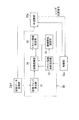
図1は、本発明の一実施形態を適用した被写体追尾システムを有するデジタルカメラの内部構成を概略的に示すブロック図である。
Embodiments of the present invention will be described below with reference to the drawings.
FIG. 1 is a block diagram schematically showing an internal configuration of a digital camera having a subject tracking system to which an embodiment of the present invention is applied.
デジタルカメラ10は、撮影光学系11、撮像素子12、AFE(Analog Front End)13、DSP(Digital Signal Processor)23、操作入力部14、及びレンズ駆動部15等によって構成される。
The
撮影光学系11は、撮像素子12に光学的に接続される。撮影光学系11を透過する被写体の光学像が撮像素子12の受光面に入射される。撮像素子12は、例えばCCDである。受光面において被写体の光学像が受光されることにより、光学像に相当する画像信号が生成される。
The photographing
撮影光学系11は、フォーカスレンズ(図示せず)やズームレンズ(図示せず)などの複数のレンズにより構成される。フォーカスレンズ及びズームレンズは光軸方向に移動自在である。フォーカスレンズを移動させることにより被写体像を撮像素子12の受光面に結像させることが出来る。ズームレンズをフォーカスレンズに対して相対的に移動させることにより撮影光学系11の焦点距離を調整可能である。
The photographing
フォーカスレンズ及びズームレンズは、操作者により手動で光軸方向に移動させることが可能である。或いは、フォーカスレンズ及びズームレンズはレンズ駆動部15によって駆動され、移動させることも可能である。特に、フォーカスレンズを移動させることによる合焦位置調整は、後述するようにオートフォーカス(AF)機能を実行することにより自動的に行わせることが可能である。
The focus lens and zoom lens can be manually moved in the optical axis direction by an operator. Alternatively, the focus lens and the zoom lens can be driven and moved by the
撮影光学系11と撮像素子12の間には、絞り16とシャッタ17とが配置される。絞り16の開度を調整することにより、撮像素子12の受光面に入射する光の照度が調整される。シャッタ17の開閉により被写体光束の通過と遮光が切替えられる。絞り16は絞り駆動部18によって駆動され、開度調整が行なわれる。シャッタ17はシャッタ駆動部19によって駆動され、開閉が実行される。
A
なお、レンズ駆動部15、絞り駆動部18、及びシャッタ駆動部19は、DSP23に接続され、それぞれの動作は、DSP23によって制御される。
The
撮像素子12は、AFE13を介してDSP23に接続される。DSP23からAFE13にクロック信号が出力される。AFE13は、クロック信号に基づいてフレーム信号及び撮像素子駆動信号を生成する。撮像素子駆動信号は撮像素子12に送信される。撮像素子12は、撮像素子駆動信号に基づいて画像信号を生成する。
The
なお、撮像素子12の受光面には、マトリックス状に画素が配列される。例えば、有効画素領域にはm×nに等分割された位置それぞれに画素が配列される。各画素における受光量に応じて画素信号が生成される。画像信号は、有効画素領域における複数の画素が生成する複数の画素信号によって形成される。
Note that pixels are arranged in a matrix on the light receiving surface of the
生成した画像信号はAFE13に送信される。画像信号はAFE13において相関二重サンプリング、ゲイン調整、及びA/D変換が施され、画像データに変換される。画像データはDSP23に送信される。
The generated image signal is transmitted to the
DSP23には、信号処理の作業用のメモリであるDRAM(Dynamic Random Access Memory)20が接続される。DSP23に送信された画像データは、DRAM20に一時格納される。DSP23により、DRAM20に格納された画像データに対して所定のデータ処理が施される。
Connected to the
DSP23には、液晶モニタ21が接続される。所定のデータ処理が施された画像データは、液晶モニタ21に送信される。送信された画像データに相当する画像が液晶モニタ21に表示可能である。
A liquid crystal monitor 21 is connected to the
また、DSP23には、外部カードインターフェース22が接続される。後述するレリーズ動作を実行するときに、所定の信号処理の施された画像データは外部カードインターフェース22に接続される外部メモリ(図示せず)に格納される。
Further, an
また、DSP23には、デジタルカメラ10を操作するためのコマンド入力を行なうための操作入力部14が接続される。操作入力部14は、レリーズボタン(図示せず)、多機能十字キー(図示せず)、電源ボタン(図示せず)などによって構成される。操作者による操作入力部14へのコマンド入力に応じて、DSP23はデジタルカメラ10の各部位に必要な動作を行なわせる。
The
例えば、レリーズボタンを半押しすることにより第1のスイッチ(図示せず)がONに切替わり、露出調整及び合焦位置調整が行われる。すなわち、露出調整において絞り16の開度、シャッタスピード調整、及びDSP23におけるゲイン調整が行なわれる。合焦位置調整において、後述するように所望の被写体光束を撮像素子12の受光面に結像させるように、フォーカスレンズ(図示せず)が駆動される。
For example, when a release button is half-pressed, a first switch (not shown) is turned ON, and exposure adjustment and focus position adjustment are performed. That is, in the exposure adjustment, the aperture of the
また、レリーズボタンを全押しすることにより第2のスイッチ(図示せず)がONに切替わりシャッタ17の開閉、静止画像の撮像を行なうように撮像素子12が駆動される。
Further, when the release button is fully pressed, the second switch (not shown) is turned on, and the
DSP23の内部構成について、図2を用いてさらに詳細に説明する。図2は、DSP23の内部構成を概略的に示すブロック図である。DSP23には、前段データ処理部23p1、後段データ処理部23p2、追尾部30(被写体追尾システム)、AF調整部23a、及び制御部23cによって構成される。
The internal configuration of the
前段データ処理部23p1には、AFE13から画像データが送信される。前段データ処理部23p1によって画像データはDRAM20に格納される。また、画像データに対して、色補間処理、ホワイトバランス処理、及び輝度信号生成処理等の所定のデータ処理が施される。また、所定のデータ処理の施された画像データは、後段データ処理部23p2に送信される。
Image data is transmitted from the
後段データ処理部23p2においても、画像データに対してクランプ処理やブランキング処理等の所定のデータ処理が施される。後段データ処理部23p2において所定のデータ処理を施した画像データは液晶モニタ21及び外部カードインターフェース22を介して外部メモリに送信される。
Also in the subsequent data processing unit 23p2, predetermined data processing such as clamping processing and blanking processing is performed on the image data. Image data subjected to predetermined data processing in the subsequent data processing unit 23p2 is transmitted to the external memory via the liquid crystal monitor 21 and the
追尾部30及びAF調整部23aにも、前段データ処理部23p1から画像データが送信される。送信された画像データに基づいて、追尾部30及びAF調整部23aにより、所望の被写体を撮像素子12の受光面に結像させるためのフォーカスレンズの駆動位置が求められる。
Image data is also transmitted from the preceding data processing unit 23p1 to the
更に説明すると、追尾部30により、撮影画像全体の中の何処かの領域がスキャン領域(追尾領域)に設定される。なお、スキャン領域とは、受光面に合焦させる所望の被写体を含ませるための領域である。所望の被写体である追尾対象体が撮影画像の中で移動する場合には、移動する領域を連続的にスキャン領域に設定することにより、追尾対象体を追尾することが可能である。
More specifically, the
AF調整部23aにより、スキャン領域に含まれる被写体を受光面に結像させるためのフォーカスレンズの駆動位置が求められる。なお、フォーカスレンズの駆動位置は、コントラスト方式、すなわち、フォーカスレンズを移動させながらスキャン領域のコントラストを検出し、コントラストを最大にさせるフォーカスレンズの位置をフォーカスレンズ駆動位置として求める方式に基づいて、実行される。なお、フォーカスレンズの駆動位置は、従来公知のいかなるAF動作により求められても良い。例えば、公知の位相差方式によって焦点検出を行なわせる構成と組合わせても良い。
The
なお、デジタルカメラ10には、撮影画像全体の中の特定の位置の被写体を合焦させる固定AF機能と撮影画像の中で移動中の被写体を合焦させる追尾AF機能とが設けられる。いずれかのAF機能を実行させるかは、操作入力部14に対するコマンド入力により選択可能である。
The
制御部23cには、操作入力部14からコマンド入力に応じた入力信号が送信される。受信した入力信号に応じて、前段データ処理部23p1、後段データ処理部23p2、追尾部30、及びAF調整部23aの動作の制御及びデジタルカメラ10の各部位の制御が、制御部23cによって実行される。
An input signal corresponding to a command input is transmitted from the
例えば、前述の露出調整を行うときに、絞り駆動部18による絞り16の駆動は、制御部23cに制御される。また、シャッタ17の開閉を行うときに、シャッタ駆動部19によるシャッタ17の開閉は、制御部23cにより制御される。
For example, when the exposure adjustment described above is performed, the driving of the
また、合焦位置調整を行うときに、レンズ駆動部15によるフォーカスレンズの駆動は、制御部23cにより制御される。制御部23cには、AF調整部23aが求めたフォーカスレンズの駆動位置に相当するレンズ位置信号が送信される。制御部23cによるレンズ駆動部15の制御は、レンズ位置信号に基づいて実行される。
Further, when the focus position adjustment is performed, the driving of the focus lens by the
次に、追尾部30の構成及び動作について、図3〜図5を用いて詳細に説明する。図3は、追尾部30の内部構成を概略的に示すブロック図である。追尾部30は、画素ブロック算出部31、スキャン領域初期設定部32、候補領域設定部33、画像認識部34、及びスキャン領域設定部35によって構成される。なお、各部位の動作は制御部23cにより制御される。
Next, the configuration and operation of the
追尾AF機能を実行するときには、前段データ処理部23p1から有効画素領域の各画素の輝度がデータとして、画素ブロック算出部31に入力される。画素ブロック算出部31では、追尾の処理を容易にするために画素ブロックの輝度が計算される。
When the tracking AF function is executed, the luminance of each pixel in the effective pixel region is input to the pixel
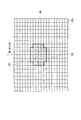
画素ブロック12bとは、図4に示すように、有効画素領域AAを例えば20×20に等分割した領域であって、互いに隣合う複数の画素、例えば10×10個の画素12pによって形成される。画素ブロック12bの輝度は、画素ブロック12bを形成する画素12pの輝度の平均値を算出することにより求められる。画素ブロック12bの輝度はデータとして画像認識部34に送られる。
As shown in FIG. 4, the
また、AF機能を実行するときには、スキャン領域初期設定部32により撮像素子12の有効画素領域AAの中心がスキャン領域の中心に定められる。中心の位置が定められることによりスキャン領域の初期設定が行なわれる。
When executing the AF function, the scan area
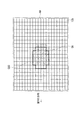
図5に示すように、スキャン領域SAは、領域の中心Cから上下に6行4列に並んだ画素ブロック12bと中心Cから左右に4行6列に並んだ画素ブロック12bとによって形成される。
As shown in FIG. 5, the scan area SA is formed by
なお、有効画素領域AAには縦方向と横方向に延びる2つの画素ブロック12bの境界線があるが、その交点のいずれかをスキャン領域SAの中心Cに定め、任意の位置にスキャン領域SAを設定可能である。スキャン領域SAの設定は操作入力部14に対するコマンド入力により行われる。
The effective pixel area AA has a boundary line between two
初期設定されたスキャン領域SAがデータとして、候補領域設定部33に送信される。候補領域設定部33では、スキャン領域SAから周囲の8方向に移動させたスキャン領域SAと同じ形態の領域が候補領域に設定される。
The initially set scan area SA is transmitted to the candidate
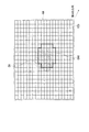
候補領域として設定するためのスキャン領域からの方向は、第1〜第8の方向が定められている。図5において、上下左右の4方向がそれぞれ第1、第5、第3、第7の方向に定められる。また、図5において、左上方向、左下方向、右下方向、右上方向がそれぞれ第2、第4、第6、第8の方向に定められる。 The first to eighth directions are defined as directions from the scan area for setting as a candidate area. In FIG. 5, four directions of up, down, left, and right are defined as first, fifth, third, and seventh directions, respectively. In FIG. 5, the upper left direction, the lower left direction, the lower right direction, and the upper right direction are defined as second, fourth, sixth, and eighth directions, respectively.
スキャン領域SAから第1の方向に画素ブロック12b一つ分移動させた領域が第1の候補領域CA1に設定される(図6参照)。スキャン領域SAから第2の方向に画素ブロック12b一つ分移動させた領域が第2の候補領域CA2に設定される(図7参照)。スキャン領域SAから第3の方向に画素ブロック12b一つ分移動させた領域が第3の候補領域CA3に設定される(図8参照)。スキャン領域SAから第4の方向に画素ブロック12b一つ分移動させた領域が第4の候補領域CA4に設定される(図9参照)。スキャン領域SAから第5の方向に画素ブロック12b一つ分移動させた領域が第5の候補領域CA5に設定される(図10参照)。スキャン領域SAから第6の方向に画素ブロック12b一つ分移動させた領域が第6の候補領域CA6に設定される(図11参照)。スキャン領域SAから第7の方向に画素ブロック12b一つ分移動させた領域が第7の候補領域CA7に設定される(図12参照)。スキャン領域SAから第8の方向に画素ブロック12b一つ分移動させた領域が第8の候補領域CA8に設定される(図13参照)。
A region moved by one
設定された第1〜第8の候補領域CA1〜CA8がデータとして、画像認識部34に送信される。また、スキャン領域初期設定部32に初期設定されたスキャン領域SAがデータとして、画像認識部34にも送信される。さらに、画像認識部34には、AFE13から画像データが送られる。
The set first to eighth candidate areas CA1 to CA8 are transmitted to the
画像認識部34では、各フレームの画像データの中からスキャン領域SA及び第1〜第8の候補領域CA1〜CA8における画像に相当するデータ成分が抽出される。なお、抽出されるデータ成分は、各領域を形成する画素ブロック12bの輝度に相当する。
The
例えば、第1のタイミングで送られる画像データにおけるスキャン領域SAでは図14に示すように、左から右、上から下の画素ブロック12bの順番に、120、30、60、55、70、110、100、70、40、105、40、85、95、65、25、40、150、120、60、30、25、45、100、120、110、95、80、50、90、75、80、20が輝度として抽出される。 For example, in the scan area SA in the image data sent at the first timing, as shown in FIG. 14, 120, 30, 60, 55, 70, 110, 120, 30, 60, 55, 70, 110, 100, 70, 40, 105, 40, 85, 95, 65, 25, 40, 150, 120, 60, 30, 25, 45, 100, 120, 110, 95, 80, 50, 90, 75, 80, 20 is extracted as the luminance.
抽出されたデータ成分に基づいて、スキャン領域SA及び第1〜第8の候補領域CA1〜CA8における各画素ブロック12bの輝度の2値化が行なわれる。すなわち、各領域に含まれる複数の画素ブロック12bにおける輝度の平均値が求められ、平均値より大きな輝度である画素ブロック12bの輝度は1に変換され、平均値より小さな輝度である画素ブロック12bの輝度は0に変換される。
Based on the extracted data components, the luminance of each
図14に示したスキャン領域の輝度の平均値は73.75であり、それぞれの画素ブロック12bの輝度は2値化により図15に示すように、左から右、上から下の画素ブロック12bの順番に1、0、0、0、0、1、1、0、0、1、0、1、1、0、0、0、1、1、0、0、0、0、1、1、1、1、1、0、1、1、1、0に変換される。
The average value of the brightness of the scan area shown in FIG. 14 is 73.75, and the brightness of each
2値化された各画素ブロック12bの輝度はデータとして、領域毎にスキャン領域設定部35に送られる。スキャン領域設定部35では、スキャン領域SAに含まれる被写体が次のタイミングの撮像により生成される画像データにおいて、第1〜第8の候補領域CA1〜CA8のいずれに移動したかが推測される。なお、この推測は、スキャン領域における各画素ブロック12bの2値化された輝度と次のタイミングの画像データの第1〜第8の候補領域CA1〜CA8それぞれにおける各画素ブロック12bの2値化された輝度とに基づいて行なわれる。
The binarized brightness of each
第1〜第8の候補領域CA1〜CA8の中からの選択は、第1〜第8の判定値の算出、第1の判定、及び第2の判定によって行なわれる。それぞれの動作について以下に詳細に説明する。 Selection from the first to eighth candidate areas CA1 to CA8 is performed by calculation of the first to eighth determination values, the first determination, and the second determination. Each operation will be described in detail below.
第1〜第8の判定値とは、スキャン領域SAの画像と第1〜第8の候補領域CA1〜CA8それぞれの画像との一致性を示す計算値である。第1〜第8の判定値は、スキャン領域SA内と第1〜第8の候補領域CA1〜CA8内において相対的に同じ位置にある画素ブロック12bにおける2値化された輝度を比較し、不一致となる画素ブロック12bの個数を数えることにより算出される。従って、第1〜第8の判定値が低い程、スキャン領域SAの画像との一致性が高いと推測される。
The first to eighth determination values are calculated values indicating the coincidence between the image of the scan area SA and each of the first to eighth candidate areas CA1 to CA8. The first to eighth determination values are inconsistent by comparing the binarized luminance in the
スキャン領域設定部35はEXOR回路(図示せず)を有しており、両画素ブロック12bにおける2値化された輝度がEXOR回路に入力される。両画素ブロック12bにおける2値化された輝度が一致するときには0が返され、2値化された輝度が異なるときには1が返される。
The scan
例えば、第1の候補領域CA1における2値化された輝度は、図16に示すような値を有している。スキャン領域SA内と第1の候補領域CA1内の相対的位置が同じ画素ブロック12bすべてに対して、2値化された輝度がEXOR回路に入力されると、左から右、上からの下の画素ブロック12bの順番に1、0、0、1、1、0、0、1、0、1、1、0、0、0、0、1、0、1、0、1、0、0、0、0、1、0、0、0、1、0、0、0の値が出力される。スキャン領域SAと第1の候補領域CA1との比較において、EXOR回路から1の値が出力された回数が第1の判定値U(exor)として数えられる。
For example, the binarized luminance in the first candidate area CA1 has a value as shown in FIG. When the binarized luminance is input to the EXOR circuit for all the pixel blocks 12b having the same relative position in the scan area SA and the first candidate area CA1, the left to right and the top to
同様に、スキャン領域SAと第2の候補領域CA2との比較が行なわれ、EXOR回路から1の値が出力された回数が第2の判定値UL(exor)として数えられる。同様に、スキャン領域SAと第3の候補領域CA3との比較が行なわれ、EXOR回路から1の値が出力された回数が第3の判定値L(exor)として数えられる。同様に、スキャン領域SAと第4の候補領域CA4との比較が行なわれ、EXOR回路から1の値が出力された回数が第4の判定値DL(exor)として数えられる。同様に、スキャン領域SAと第5の候補領域CA5との比較が行なわれ、EXOR回路から1の値が出力された回数外第5の判定値D(exor)として数えられる。同様に、スキャン領域SAと第6の候補領域CA6との比較が行なわれ、EXOR回路から1の値が出力された回数が第6の判定値DR(exor)として数えられる。同様に、スキャン領域SAと第7の候補領域CA7との比較が行なわれ、EXOR回路から1の値が出力された回数が第7の判定値R(exor)として数えられる。同様に、スキャン領域SAと第8の候補領域CA8との比較が行なわれ、EXOR回路から1の値が出力された回数が第8の判定値UR(exor)として数えられる。 Similarly, the scan area SA and the second candidate area CA2 are compared, and the number of times a value of 1 is output from the EXOR circuit is counted as the second determination value UL (exor). Similarly, the scan area SA is compared with the third candidate area CA3, and the number of times the value of 1 is output from the EXOR circuit is counted as the third determination value L (exor). Similarly, the scan area SA is compared with the fourth candidate area CA4, and the number of times the value of 1 is output from the EXOR circuit is counted as the fourth determination value DL (exor). Similarly, the scan area SA and the fifth candidate area CA5 are compared, and counted as the fifth determination value D (exor) outside the number of times when a value of 1 is output from the EXOR circuit. Similarly, the scan area SA is compared with the sixth candidate area CA6, and the number of times the value of 1 is output from the EXOR circuit is counted as the sixth determination value DR (exor). Similarly, the scan area SA is compared with the seventh candidate area CA7, and the number of times that a value of 1 is output from the EXOR circuit is counted as the seventh determination value R (exor). Similarly, the scan area SA is compared with the eighth candidate area CA8, and the number of times the value of 1 is output from the EXOR circuit is counted as the eighth determination value UR (exor).
第1〜第8の判定値U(exor)、UL(exor)、L(exor)、DL(exor)、D(exor)、DR(exor)、R(exor)、UR(exor)が求められると、次に第1の判定が行なわれる。 First to eighth determination values U (exor), UL (exor), L (exor), DL (exor), D (exor), DR (exor), R (exor), UR (exor) are obtained. Then, a first determination is made.
第1の判定では、被写体の大まかな移動方向である粗方向が第1、第3、第5、第7の方向の中のいずれであるかの判定が行なわれる。先ず、粗方向の判定のために第1〜第4の粗判定値が算出される。 In the first determination, a determination is made as to which of the first, third, fifth, and seventh directions is the rough direction, which is a rough movement direction of the subject. First, first to fourth rough judgment values are calculated for judgment of the rough direction.
第1、第2、第8の判定値U(exor)、UL(exor)、UR(exor)の合計値が、第1の粗判定値UUとして算出される。また、第2〜第4の判定値UL(exor)、L(exor)、DL(exor)の合計値が、第2の粗判定値LLとして算出される。また、第4〜第6の判定値DL(exor)、D(exor)、DR(exor)の合計値が第3の粗判定値DDとして算出される。また、第6〜第8の判定値DR(exor)、R(exor)、UR(exor)の合計値が第4の粗判定値RRとして算出される。 A total value of the first, second, and eighth determination values U (exor), UL (exor), and UR (exor) is calculated as the first rough determination value UU. In addition, the total value of the second to fourth determination values UL (exor), L (exor), and DL (exor) is calculated as the second rough determination value LL. Further, the total value of the fourth to sixth determination values DL (exor), D (exor), and DR (exor) is calculated as the third rough determination value DD. The total value of the sixth to eighth determination values DR (exor), R (exor), and UR (exor) is calculated as the fourth rough determination value RR.
第1〜第4の粗判定値UU、LL、DD、RRの中の最小値が判定される。最小値となる粗判定値に対応する方向が、被写体の移動した粗方向であると判定される。第1〜第4の粗判定値に対応する方向は、それぞれ第1、第3、第5、第7の方向である。 The minimum value among the first to fourth coarse determination values UU, LL, DD, RR is determined. It is determined that the direction corresponding to the rough determination value that is the minimum value is the rough direction in which the subject has moved. The directions corresponding to the first to fourth rough judgment values are the first, third, fifth, and seventh directions, respectively.
第2の判定においては、第1の判定により判定された粗方向を正方向成分として含む方向の中から、被写体が移動した方向の判定が行なわれる。すなわち、第1の粗判定値UUが最小であるときは、被写体の移動方向は第1、第2、第8の方向のいずれかの方向であると判定される。第2の粗判定値LLが最小であるときは、被写体の移動方向は第2〜第4の方向いずれかの方向であると判定される。第3の粗判定値DDが最小であるときは、被写体の移動方向は第4〜第6の方向いずれかの方向であると判定される。第4の粗判定値RRが最小であるときは、被写体の移動方向は第6〜第8の方向いずれかの方向であると判定される。 In the second determination, the direction in which the subject has moved is determined from the directions including the rough direction determined in the first determination as the positive direction component. That is, when the first rough determination value UU is minimum, it is determined that the moving direction of the subject is one of the first, second, and eighth directions. When the second rough determination value LL is minimum, it is determined that the moving direction of the subject is one of the second to fourth directions. When the third rough determination value DD is minimum, it is determined that the moving direction of the subject is any one of the fourth to sixth directions. When the fourth rough determination value RR is the minimum, it is determined that the moving direction of the subject is any one of the sixth to eighth directions.
具体的には、選択された粗方向に含まれる3方向に対応する3つの判定値の最小値が判定される。最小値であると判定された判定値に対応する候補領域が被写体の移動した領域であると判定され、選択される。選択された候補領域は、スキャン領域SAとして再設定される。 Specifically, the minimum value of the three determination values corresponding to the three directions included in the selected rough direction is determined. The candidate area corresponding to the determination value determined to be the minimum value is determined to be the area where the subject has moved and is selected. The selected candidate area is reset as the scan area SA.
なお、固定AF機能を実行させるときには、追尾部30の中でスキャン領域初期設定部32のみが駆動され、画素ブロック算出部31、候補領域設定部33、画像認識部34、及びスキャン領域設定部35の駆動は停止される。
When the fixed AF function is executed, only the scan region
スキャン領域初期設定部32の駆動により設定されたスキャン領域SAは画像認識部34及びスキャン領域設定部35を介してAF調整部23aにデータとして送られる。なお、追尾AF機能と異なり、スキャン領域SAは最初に設定されたスキャン領域SAのまま固定される。
The scan area SA set by driving the scan area
次に、追尾AF機能を実行するときに追尾部30において行なわれるスキャン領域SAの設定のために行なわれる処理を図17〜図19のフローチャートを用いて説明する。図17は、スキャン領域SAの設定のために行なわれる処理を説明するためのフローチャートである。図18は、第1の判定を実行するときの処理を説明するためのフローチャートである。図19は、第2の判定を実行するときの処理を説明するためのフローチャートである。
Next, the process performed for setting the scan area SA performed in the
追尾AF機能を実行させるとき、すなわち追尾AF機能実行に切替えるコマンド入力をした後にレリーズボタンが半押しされたときに本処理が開始される。なお、本処理は、デジタルカメラ10の電源がOFFに切替えられるか、追尾AF機能の実行が解除されるまで繰返される。
This process is started when the tracking AF function is executed, that is, when the release button is half-pressed after inputting a command for switching to the tracking AF function execution. This process is repeated until the
ステップS100において、スキャン領域の初期設定が行なわれる。操作者によるコマンド入力により定められた撮影画像の枠内の点を中心Cとしてスキャン領域SAが設定される。次のステップS101において、追尾部30に1フレームの画像データが受信される。
In step S100, the scan area is initially set. A scan area SA is set with a point C in the frame of the captured image determined by command input by the operator as the center C. In the next step S101, the
画像データを受信するとステップS102に進む。ステップS102では、設定されたスキャン領域SAに基づいて、第1〜第8の候補領域CA1〜CA8の設定が行なわれる。次のステップS103において、ステップS101で受信した画像データからスキャン領域SAのデータ成分が抽出される。抽出されたデータ成分に基づいて、スキャン領域SAの画素ブロック12bの輝度が2値化される。
When the image data is received, the process proceeds to step S102. In step S102, the first to eighth candidate areas CA1 to CA8 are set based on the set scan area SA. In the next step S103, the data component of the scan area SA is extracted from the image data received in step S101. Based on the extracted data component, the luminance of the
スキャン領域SAの輝度の2値化の次に、ステップS104に進む。ステップS104では、次のフレームで生成された画像データが追尾部30に受信される。
After the binarization of the luminance of the scan area SA, the process proceeds to step S104. In step S <b> 104, the image data generated in the next frame is received by the
次のステップS105では、ステップS104で受信した画像データから第1〜第8の候補領域CA1〜CA8のデータ成分が抽出される。抽出されたデータ成分に基づいて第1〜第8の候補領域CA1〜CA8それぞれの画素ブロック12bの輝度が2値化される。2値化の終了後、ステップS106に進む。
In the next step S105, the data components of the first to eighth candidate areas CA1 to CA8 are extracted from the image data received in step S104. Based on the extracted data components, the luminance of the
ステップS106では、スキャン領域SAにおける2値化された輝度と第1〜第8の候補領域CA1〜CA8における2値化された輝度とに基づいて、第1〜第8の判定値U(exor)、UL(exor)、L(exor)、DL(exor)、D(exor)、DR(exor)、R(exor)、UR(exor)が算出される。 In step S106, the first to eighth determination values U (exor) based on the binarized luminance in the scan area SA and the binarized luminance in the first to eighth candidate areas CA1 to CA8. , UL (exor), L (exor), DL (exor), D (exor), DR (exor), R (exor), and UR (exor) are calculated.
次にステップS107に進み、第1〜第8の判定値U(exor)、UL(exor)、L(exor)、DL(exor)、D(exor)、DR(exor)、R(exor)、UR(exor)により、第1〜第4の粗判定値UU、LL、DD、RRが算出される。 In step S107, the first to eighth determination values U (exor), UL (exor), L (exor), DL (exor), D (exor), DR (exor), R (exor), First to fourth rough judgment values UU, LL, DD, and RR are calculated by UR (exor).
次にステップS200において、第1の判定のサブルーチンが実行されることにより、第2の判定を行なうために用いる3つの判定値が選択される。第1の判定のサブルーチンが終了すると、ステップS300において、第2の判定のサブルーチンが実行される。第2の判定のサブルーチンが実行されることにより、ステップS102の画像データにおいてスキャン領域SAに含まれる被写体をステップS104の画像データにおいて含む領域が、第1〜第8の候補領域CA1〜CA8の中から選択される。 Next, in step S200, the first determination subroutine is executed to select three determination values used for performing the second determination. When the first determination subroutine is completed, the second determination subroutine is executed in step S300. By executing the second determination subroutine, the area including the subject included in the scan area SA in the image data in step S104 in the image data in step S102 is among the first to eighth candidate areas CA1 to CA8. Selected from.
第2の判定のサブルーチンが終了すると、ステップS108において選択された候補領域が新たにスキャン領域SAとして設定される。ステップS108の処理の後は、ステップS102に戻り、ステップS102〜ステップS108の処理が繰返される。 When the second determination subroutine is completed, the candidate area selected in step S108 is newly set as the scan area SA. After the process of step S108, the process returns to step S102, and the processes of step S102 to step S108 are repeated.
次にステップS200で実行される第1の判定のサブルーチン及びステップS300で実行される第2の判定のサブルーチンについて説明する。ステップS200のサブルーチンが開始すると、先ずステップS201において第1の粗判定値UUと第3の粗判定値DDのいずれが小さいかが判定される。第1の粗判定値UUが小さいときは、ステップS202に進む。 Next, the first determination subroutine executed in step S200 and the second determination subroutine executed in step S300 will be described. When the subroutine of step S200 starts, first, in step S201, it is determined which of the first rough determination value UU and the third rough determination value DD is smaller. When the first rough judgment value UU is small, the process proceeds to step S202.
ステップS202では、第1の粗判定値UUと第2の粗判定値LLとのいずれが小さいかが判定される。第1の粗判定値UUが小さいときは、ステップS203に進む。ステップS203では、第1の粗判定値UUと第4の粗判定値RRとのいずれが小さいかが判定される。第1の粗判定値UUが小さいときは、ステップS204に進む。 In step S202, it is determined which of the first rough determination value UU and the second rough determination value LL is smaller. When the first rough judgment value UU is small, the process proceeds to step S203. In step S203, it is determined which of the first rough determination value UU and the fourth rough determination value RR is smaller. When the first rough judgment value UU is small, the process proceeds to step S204.
ステップS204では、被写体の移動した粗方向が第1の方向であると判定される。第1の粗判定値UUを算出するための第1、第2、第8の判定値U(exor)、UL(exor)、UR(exor)が第2の判定を行なうために選択される。第1の判定値U(exor)が第1の確定用判定値N1に設定される。第2の判定値UL(exor)が第2の確定用判定値N2に設定される。第8の判定値UR(exor)が第3の確定用判定値N3に設定される。 In step S204, it is determined that the rough direction in which the subject has moved is the first direction. First, second, and eighth determination values U (exor), UL (exor), and UR (exor) for calculating the first rough determination value UU are selected to perform the second determination. The first determination value U (exor) is set to the first determination value N1. The second determination value UL (exor) is set to the second determination value N2. The eighth determination value UR (exor) is set to the third determination value N3.
ステップS201において、第3の粗判定値DDが小さいときはステップS205に進む。ステップS205では、第3の粗判定値DDと第2の粗判定値LLとのいずれが小さいかが判定される。第3の粗判定値DDが小さいときは、ステップS206に進む。ステップS206では、第3の粗判定値DDと第4の粗判定値RRとのいずれが小さいかが判定される。第3の粗判定値DDが小さいときは、ステップS207に進む。 In step S201, when the third rough judgment value DD is small, the process proceeds to step S205. In step S205, it is determined which of the third rough determination value DD and the second rough determination value LL is smaller. When the third rough determination value DD is small, the process proceeds to step S206. In step S206, it is determined which of the third rough determination value DD and the fourth rough determination value RR is smaller. When the third rough judgment value DD is small, the process proceeds to step S207.
ステップS207では、被写体の移動した粗方向が第3の方向であると判定される。第3の粗判定値DDを算出するための第4〜第6の判定値DL(exor)、D(exor)、DR(exor)が第2の判定を行なうために選択される。第5の判定値D(exor)が第1の確定用判定値N1に設定される。第4の判定値DL(exor)が第2の確定用判定値N2に設定される。第6の判定値DR(exor)が第3の確定用判定値N3に設定される。 In step S207, it is determined that the rough direction in which the subject has moved is the third direction. The fourth to sixth determination values DL (exor), D (exor), and DR (exor) for calculating the third rough determination value DD are selected to perform the second determination. The fifth determination value D (exor) is set to the first determination value N1. The fourth determination value DL (exor) is set to the second determination value N2. The sixth determination value DR (exor) is set to the third determination value N3.
ステップS202又はステップS205において第2の粗判定値LLの方が小さいときは、ステップS208に進む。ステップS208では、第2の粗判定値LLと第4の粗判定値RRとのいずれが小さいかが判定される。第2の粗判定値LLが小さいときは、ステップS209に進む。 When the second rough judgment value LL is smaller in step S202 or step S205, the process proceeds to step S208. In step S208, it is determined which of the second rough determination value LL and the fourth rough determination value RR is smaller. When the second rough judgment value LL is small, the process proceeds to step S209.
ステップS209では、被写体の移動した粗方向が第2の方向であると判定される。第2の粗判定値LLを算出するための第2〜第4の判定値UL(exor)、L(exor)、DL(exor)が第2の判定を行なうために選択される。第3の判定値L(exor)が第1の確定用判定値N1に設定される。第2の判定値UL(exor)が第2の確定用判定値N2に設定される。第4の判定値DL(exor)が第3の確定用判定値N3に設定される。 In step S209, it is determined that the coarse direction in which the subject has moved is the second direction. The second to fourth determination values UL (exor), L (exor), and DL (exor) for calculating the second rough determination value LL are selected to perform the second determination. The third determination value L (exor) is set to the first determination value N1. The second determination value UL (exor) is set to the second determination value N2. The fourth determination value DL (exor) is set to the third determination value N3.
ステップS203、ステップS206、又はステップS208において第4の粗判定値RRの方が小さいときは、ステップS210に進む。 When the fourth rough judgment value RR is smaller in step S203, step S206, or step S208, the process proceeds to step S210.
ステップS210では、被写体の移動した粗方向が第4の方向であると判定される。第4の粗判定値RRを算出するための第6〜第8の判定値DR(exor)、R(exor)、UR(exor)が第2の判定を行なうために選択される。第7の判定値R(exor)が第1の確定用判定値N1に設定される。第8の判定値UR(exor)が第2の確定用判定値N2に設定される。第6の判定値DR(exor)が第3の確定用判定値N3に設定される。 In step S210, it is determined that the coarse direction in which the subject has moved is the fourth direction. The sixth to eighth determination values DR (exor), R (exor), and UR (exor) for calculating the fourth rough determination value RR are selected to perform the second determination. The seventh determination value R (exor) is set to the first determination value N1. The eighth determination value UR (exor) is set to the second determination value N2. The sixth determination value DR (exor) is set to the third determination value N3.
ステップS204、ステップS207、ステップS209、又はステップS210の処理の後に、第1の判定のサブルーチンは終了し、ステップS300の第2の判定のサブルーチンが開始される。 After the processing of step S204, step S207, step S209, or step S210, the first determination subroutine is terminated, and the second determination subroutine of step S300 is started.
ステップS300のサブルーチンを開始すると、先ずステップS301において第1の確定用判定値N1と第2の確定用判定値N2とのいずれが小さいかについての判定が行なわれる。第1の確定用判定値N1の方が小さいときにはステップS302に進む。 When the subroutine of step S300 is started, first, in step S301, a determination is made as to which of the first determination value N1 and the second determination value N2 is smaller. When the first determination determination value N1 is smaller, the process proceeds to step S302.
ステップS302では、第1の確定用判定値と第3の確定用判定値N3とのいずれが小さいかについての判定が行なわれる。第1の確定用判定値N1の方が小さいときにはステップS303に進む。 In step S302, a determination is made as to which of the first determination value and the third determination value N3 is smaller. When the first determination determination value N1 is smaller, the process proceeds to step S303.
ステップS303では、被写体の移動した方向が第1の確定用判定値N1に設定された判定値に対応する方向と判定される。設定された判定値に対応する候補領域がステップS108においてスキャン領域に設定される候補領域として選択される。 In step S303, it is determined that the direction in which the subject has moved is the direction corresponding to the determination value set as the first determination determination value N1. A candidate area corresponding to the set determination value is selected as a candidate area to be set as a scan area in step S108.
ステップS301において、第2の確定用判定値N2の方が小さいときにはステップS304に進む。ステップS304では、第2の確定用判定値N2と第3の確定用判定値N3とのいずれが小さいかについての判定が行なわれる。第2の確定用判定値N2の方が小さいときにはステップS305に進む。 In step S301, when the second determination determination value N2 is smaller, the process proceeds to step S304. In step S304, a determination is made as to which of the second determination value N2 and the third determination value N3 is smaller. When the second determination value N2 is smaller, the process proceeds to step S305.
ステップS305では、被写体の移動した方向が第2の確定用判定値N2に設定された判定値に対応する方向にと判定される。設定された判定値に対応する候補領域がステップS108においてスキャン領域に設定される候補領域として選択される。 In step S305, it is determined that the direction in which the subject has moved is the direction corresponding to the determination value set in the second determination value N2. A candidate area corresponding to the set determination value is selected as a candidate area to be set as a scan area in step S108.
ステップS302又はステップS304において、第3の確定用判定値N3の方が小さいときにはステップS306に進む。 In step S302 or step S304, when the third determination value N3 is smaller, the process proceeds to step S306.
ステップS306では、被写体の移動した方向が第3の確定用判定値N3に設定された判定値に対応する方向と判定される。設定された判定値に対応する候補領域がステップS108においてスキャン領域に設定される候補領域として選択される。 In step S306, it is determined that the direction in which the subject has moved is a direction corresponding to the determination value set in the third determination value N3. A candidate area corresponding to the set determination value is selected as a candidate area to be set as a scan area in step S108.
ステップS303、ステップS305、又はステップS306の終了後、第2の判定のサブルーチンは終了し、ステップS108に進む。 After step S303, step S305, or step S306 ends, the second determination subroutine ends, and the process proceeds to step S108.
以上のような構成である本実施形態の被写体追尾システムによれば、被写体の誤追尾を低減化することが可能である。従来のようなパターンマッチングでは本実施形態における第1〜第8の判定値だけを比較し、最小の判定値に対応する候補領域を追尾先の領域と判定していた。しかし、実際に移動先でない領域の判定値が偶然に最小となることが起こりえるため、誤追尾が発生することになる。 According to the subject tracking system of the present embodiment having the above-described configuration, it is possible to reduce subject tracking errors. In conventional pattern matching, only the first to eighth determination values in the present embodiment are compared, and the candidate area corresponding to the minimum determination value is determined as the tracking destination area. However, it is possible that the determination value of the area that is not actually the movement destination will be minimized by chance, resulting in erroneous tracking.
そこで、本実施形態では、第1〜第8の判定値から算出される第1〜第4の粗判定値に基づいて被写体の移動方向を大まかに判定することにより、被写体の移動先の候補が絞り込まれる。移動先で無い領域の判定値が偶然に最小となることがあっても、粗判定値は実際に被写体の移動した方向が最小となる可能性が高い。従って、大まかな移動方向の判定に詳細な方向の判定を行なうことにより、誤追尾を低減化させ追尾精度を向上させることが可能となる。 Therefore, in the present embodiment, by roughly determining the moving direction of the subject based on the first to fourth coarse determination values calculated from the first to eighth determination values, the subject movement destination candidates are determined. It is narrowed down. Even if the judgment value of the area that is not the destination is accidentally minimized, the coarse judgment value is likely to be the smallest in the direction in which the subject actually moves. Therefore, it is possible to reduce the tracking error and improve the tracking accuracy by performing the detailed direction determination for the rough determination of the moving direction.
なお、本実施形態において、被写体の移動方向が第1〜第8の方向の8方向のいずれであるかを判定する構成であるが、4方向以上の中から判定される構成であってもよい。例えば、90度ずつ異なる4方向のいずれかを移動方向として判定する構成であれば、第1の判定により隣合う2方向の2組それぞれの合成ベクトルのいずれの方向に移動しているかについての第1の判定を行い、第2の判定において2方向のいずれに移動したかについての第2の判定を行えば良い。 In the present embodiment, the moving direction of the subject is determined as one of the eight directions of the first to eighth directions, but may be determined from four or more directions. . For example, if the configuration is such that one of four directions that differ by 90 degrees is determined as the movement direction, the first determination indicates which direction of the two combined vectors of the two adjacent directions is moving in the first determination. 1 determination may be performed, and the second determination may be made as to which of the two directions is moved in the second determination.
また、本実施形態において、第1の判定により被写体の移動方向が大まかに4方向のいずれかの方向であると判定されるが、前述のように2方向以上であれば、何方向の中から判定されても良い。 Further, in the present embodiment, it is determined by the first determination that the moving direction of the subject is roughly any one of the four directions. It may be determined.
また、本実施形態において被写体の移動した粗方向の判定のための粗判定値は、異なる3方向に対応した判定値により算出される構成であるが、粗方向を正方向成分として含む方向であって異なる2方向以上に対応した判定値により算出されれば良い。この場合第2の判定においては、粗判定値を算出した判定値に対応した数の方向の中から、被写体の移動した方向の判定が行なわれる。 In this embodiment, the rough determination value for determining the rough direction in which the subject has moved is calculated based on the determination values corresponding to the three different directions, but the direction includes the rough direction as a positive direction component. It is only necessary to calculate with determination values corresponding to two or more different directions. In this case, in the second determination, the direction in which the subject has moved is determined from the number of directions corresponding to the determination value for which the rough determination value is calculated.
また、本実施形態において、第1〜第8の候補領域CA1〜CA8は前のタイミングのフレームの画像データにおけるスキャン領域SAから第1〜第8の方向に1画素ブロック12bずつ移動させた領域であるが、移動させる画素ブロック12bの数はいくつであっても良い。また、移動させる画素ブロック12bの数は、方向に応じて異なっていても良い。ただし、移動させる距離は実質的に同じであることが好ましい。
In the present embodiment, the first to eighth candidate areas CA1 to CA8 are areas that are moved by one
また、本実施形態において、スキャン領域SA及び第1〜第8の候補領域CA1〜CA8の形状は十字形であるがどのような形状であっても良い。 Further, in the present embodiment, the shapes of the scan area SA and the first to eighth candidate areas CA1 to CA8 are cross-shaped, but any shape may be used.
また、本実施形態において、スキャン領域SA及び第1〜第8の候補領域CA1〜CA8における画素ブロック12bの輝度の2値化が行なわれているが、2値化でなくても所定の数によって階層化しても良い。更には、階層化しなくても良い。ただし、2値化を行なうことにより第1、第2の判定を高速化することが可能になる。なお、領域ごとにその平均輝度で正規化することにより、蛍光灯のフリッカ等の影響を軽減させることが可能になる。
In the present embodiment, the luminance of the
また、本実施形態において、EXOR回路を用いて、スキャン領域SAと第1〜第8の候補領域CA1〜CA8における画素ブロック12bの2値化された輝度が一致しているか否かを判定させているが、例えばEXNOR回路を用いて判定を行なわせても良い。また、他のいずれの手段により一致しているか否かの判定を行なっても良い。
In the present embodiment, the EXOR circuit is used to determine whether or not the binarized luminances of the
また、本実施形態において、撮像素子12の有効画素領域AAには画素がマトリックス状に配列される構成であるが、2次元状に配列されていればよい。
In the present embodiment, the pixels are arranged in a matrix in the effective pixel area AA of the
また、本実施形態において、追尾部30により所望の被写体を追尾させ、追尾している被写体に対してAF機能を実行させる構成であるが、追尾部30による追尾機能を他の機能に適用することは可能である。例えば、所望の被写体を追尾し、モニタ上に被写体とともに追尾されていることが表示される監視カメラや、移動する被写体を追尾させ、追尾している被写体に対して自動露出補正を行なうカメラなどにも適用可能である。
In the present embodiment, the
10 デジタルカメラ
12b 画素ブロック
12p 画素
13 AFE(Analog Front End)
23 DSP(Digital Signal Processor)
23a AF調整部
23c 制御部
23p1 前段データ処理部
30 追尾部
31 画素ブロック算出部
32 スキャン領域初期設定部
33 候補領域設定部
34 画像認識部
35 スキャン領域設定部
AA 有効画素領域
C スキャン領域の中心
CA1〜CA8 第1〜第8の候補領域
SA スキャン領域
10
23 DSP (Digital Signal Processor)
23a
Claims (6)
前記撮影画像における定められた一部の領域を、前記追尾対象体を追尾するための追尾領域に初期設定する初期設定部と、
前記追尾領域から第1の粗方向を正方向成分として有する第1、第2の方向に移動した領域である第1、第2の候補領域を設定し、前記第1の粗方向とは異なる第2の粗方向を正方向成分として有する第3、第4の方向に前記追尾領域から移動した領域である第3、第4の候補領域を設定する候補領域設定部と、
第1のタイミングで撮像された前記撮影画像における前記追尾領域の画像である基準画像を検出し、前記第1のタイミングの後の第2のタイミングで撮像された前記撮影画像における前記第1〜第4の候補領域の画像である第1〜第4の候補画像を検出する画像検出部と、
前記基準画像と前記第1〜第4の候補画像それぞれとの一致性に基づいて、前記第1のタイミングから前記第2のタイミングにおける前記追尾対象体の移動方向が、前記第1の粗方向と前記第2の粗方向とのいずれであるかを判定する第1の判定部と、
前記追尾対象体の移動方向として判定された粗方向が前記第1の粗方向であるときに前記基準画像と前記第1、第2の候補画像それぞれとの一致性に基づいて前記追尾対象体の移動方向が前記第1、第2の方向のいずれであるかを判定し、前記追尾対象体の移動方向として判定された粗方向が第2の粗方向であるときに前記基準画像と前記第3、第4の候補画像それぞれの一致性に基づいて前記追尾対象体の移動方向が前記第3、第4の方向のいずれであるかを判定する第2の判定部と、
前記第2の判定部に前記追尾対象体の移動方向として判定された方向に移動した候補領域を追尾領域として再設定する再設定部とを備える
ことを特徴とする被写体追尾システム。 A subject tracking system that tracks the movement of a tracking target that is a specific subject in continuously captured images,
An initial setting unit that initially sets a predetermined part of the captured image as a tracking region for tracking the tracking object;
First and second candidate regions, which are regions moved in the first and second directions having the first coarse direction as a positive direction component from the tracking region, are set, and are different from the first coarse direction. A candidate area setting unit that sets third and fourth candidate areas that are areas moved from the tracking area in the third and fourth directions having two coarse directions as positive direction components;
A reference image that is an image of the tracking area in the captured image captured at a first timing is detected, and the first to first images in the captured image captured at a second timing after the first timing. An image detection unit that detects first to fourth candidate images that are images of four candidate regions;
Based on the coincidence between the reference image and each of the first to fourth candidate images, the movement direction of the tracking target object from the first timing to the second timing is the first coarse direction. A first determination unit for determining which of the second coarse direction,
When the coarse direction determined as the moving direction of the tracking target object is the first coarse direction, the tracking object is determined based on the match between the reference image and each of the first and second candidate images. It is determined whether the movement direction is the first direction or the second direction, and the reference image and the third direction are determined when the coarse direction determined as the movement direction of the tracking target object is the second coarse direction. A second determination unit that determines whether the moving direction of the tracking target object is the third direction or the fourth direction based on the matching of each of the fourth candidate images;
A subject tracking system, comprising: a resetting unit that resets a candidate area that has moved in a direction determined as a moving direction of the tracking target object as a tracking area in the second determination unit.
前記画像検出部は、前記第2のタイミングで撮像された前記撮影画像における前記第5、第6の候補領域の画像である第5、第6の候補画像を検出する画像検出部と、
前記第1の判定部は、前記基準画像と前記第1〜第6の候補画像それぞれとの一致性に基づいて、前記第1のタイミングから前記第2のタイミングにおける前記追尾対象体の移動方向が、前記第1〜第3の粗方向のいずれの粗方向であるかを判定し、
前記第2の判定部は、前記追尾対象体の移動方向として判定された粗方向が前記第3の粗方向であるときに前記基準画像と前記第5、第6の候補画像それぞれとの一致性に基づいて前記追尾対象体の移動方向が前記第5、第6の方向いずれであるかを判定する
ことを特徴とする請求項1〜請求項3のいずれか1項に記載の被写体追尾システム。 The candidate area setting unit is an area moved from the tracking area in the fifth and sixth directions having a third coarse direction different from the first and second coarse directions as a positive direction component. Set the sixth candidate area,
The image detection unit detects fifth and sixth candidate images that are images of the fifth and sixth candidate regions in the captured image captured at the second timing; and
The first determination unit determines whether the moving direction of the tracking target object from the first timing to the second timing is based on matching between the reference image and each of the first to sixth candidate images. , Determine which of the first to third coarse directions is the coarse direction,
The second determination unit matches the reference image with each of the fifth and sixth candidate images when the coarse direction determined as the moving direction of the tracking target object is the third coarse direction. The subject tracking system according to any one of claims 1 to 3, wherein whether the moving direction of the tracking target object is the fifth direction or the sixth direction is determined based on the following.
前記候補領域設定部は、前記追尾領域から、前記第3の方向の逆向きの方向である第7の方向、及び前記第7の方向と前記第1の方向とを正方向成分として含む第8の方向に移動した領域である第7、第8の領域である第7、第8の候補領域を設定し、
前記画像検出部は、前記第2のタイミングで撮像された前記撮影画像における前記第7、第8の候補領域の画像である第7、第8の候補画像を検出する画像検出部と、
前記第1の判定部は、前記基準画像と前記第1〜第8の候補画像それぞれとの一致性に基づいて、前記第1のタイミングから前記第2のタイミングにおける前記追尾対象体の移動方向が、前記第1、第3、第5、第7の方向のいずれの方向であるかを判定し、
前記第2の判定部は、前記追尾対象体の移動方向として判定された方向が前記第1の方向であるときに前記基準画像と前記第1、第2、第8の候補画像それぞれとの一致性に基づいて前記追尾対象体の移動方向が前記第1、第2、第6の方向のいずれであるかを判定し、前記追尾対象体の移動方向として判定された方向が前記第3の方向であるときに前記基準画像と前記第2〜第4の候補画像それぞれとの一致性に基づいて前記追尾対象体の移動方向が前記第2〜第4の方向のいずれであるかを判定し、前記追尾対象体の移動方向として判定された方向が前記第5の方向であるときに前記基準画像と前記第4〜第6の候補画像それぞれとの一致性に基づいて前記追尾対象体の移動方向が前記第4〜第6の方向のいずれであるかを判定し、前記追尾対象体の移動方向として判定された方向が前記第7の方向であるときに前記基準画像と前記第6〜第8の候補画像それぞれとの一致性に基づいて前記追尾対象体の移動方向が前記第6〜第8の方向のいずれであるかを判定する
ことを特徴とする請求項5に記載の被写体追尾システム。 The first coarse direction and the third coarse direction are opposite to each other, the first coarse direction and the second coarse direction are perpendicular to each other, and the first coarse direction and the first coarse direction are Direction is the same direction, the second rough direction and the third direction are the same direction, the third rough direction and the fifth direction are the same direction, and the second direction The direction includes the second rough direction as a positive direction component, the fourth direction includes the third rough direction as a positive direction component,
The candidate area setting unit includes a seventh direction that is a direction opposite to the third direction from the tracking area, and an eighth component that includes the seventh direction and the first direction as positive direction components. The seventh and eighth candidate areas that are the seventh and eighth areas that are moved in the direction of
The image detection unit detects seventh and eighth candidate images that are images of the seventh and eighth candidate regions in the captured image captured at the second timing;
The first determination unit is configured to determine a movement direction of the tracking target object from the first timing to the second timing based on matching between the reference image and each of the first to eighth candidate images. , Determine which direction is the first, third, fifth, or seventh direction,
The second determination unit matches the reference image with each of the first, second, and eighth candidate images when the direction determined as the moving direction of the tracking target object is the first direction. Based on the characteristics, it is determined whether the movement direction of the tracking object is the first, second, or sixth direction, and the direction determined as the movement direction of the tracking object is the third direction. Determining whether the movement direction of the tracking target object is the second to fourth directions based on the coincidence between the reference image and each of the second to fourth candidate images. When the direction determined as the movement direction of the tracking object is the fifth direction, the movement direction of the tracking object is based on the coincidence between the reference image and each of the fourth to sixth candidate images. Is one of the fourth to sixth directions, and When the direction determined as the movement direction of the tail object is the seventh direction, the movement direction of the tracking object is determined based on the coincidence between the reference image and each of the sixth to eighth candidate images. The subject tracking system according to claim 5, wherein it is determined which of the sixth to eighth directions.
Priority Applications (2)
| Application Number | Priority Date | Filing Date | Title |
|---|---|---|---|
| JP2006072904A JP4573789B2 (en) | 2006-03-16 | 2006-03-16 | Subject tracking system |
| US11/686,578 US7990417B2 (en) | 2006-03-16 | 2007-03-15 | Targeted object pursuit system |
Applications Claiming Priority (1)
| Application Number | Priority Date | Filing Date | Title |
|---|---|---|---|
| JP2006072904A JP4573789B2 (en) | 2006-03-16 | 2006-03-16 | Subject tracking system |
Publications (2)
| Publication Number | Publication Date |
|---|---|
| JP2007251636A JP2007251636A (en) | 2007-09-27 |
| JP4573789B2 true JP4573789B2 (en) | 2010-11-04 |
Family
ID=38595464
Family Applications (1)
| Application Number | Title | Priority Date | Filing Date |
|---|---|---|---|
| JP2006072904A Expired - Fee Related JP4573789B2 (en) | 2006-03-16 | 2006-03-16 | Subject tracking system |
Country Status (2)
| Country | Link |
|---|---|
| US (1) | US7990417B2 (en) |
| JP (1) | JP4573789B2 (en) |
Families Citing this family (4)
| Publication number | Priority date | Publication date | Assignee | Title |
|---|---|---|---|---|
| JP4701111B2 (en) * | 2006-03-16 | 2011-06-15 | Hoya株式会社 | Pattern matching system and subject tracking system |
| KR101445606B1 (en) * | 2008-02-05 | 2014-09-29 | 삼성전자주식회사 | Digital photographing apparatus, method for controlling the same, and recording medium storing program to implement the method |
| US9696404B1 (en) | 2014-05-06 | 2017-07-04 | The United States Of America As Represented By The Secretary Of The Air Force | Real-time camera tracking system using optical flow feature points |
| CN111238829A (en) * | 2020-02-12 | 2020-06-05 | 上海眼控科技股份有限公司 | Method and device for determining moving state, computer equipment and storage medium |
Citations (5)
| Publication number | Priority date | Publication date | Assignee | Title |
|---|---|---|---|---|
| JPH01170288A (en) * | 1987-12-25 | 1989-07-05 | Toshiba Corp | Moving compensation inter-frame prediction device |
| JPH03106284A (en) * | 1989-09-20 | 1991-05-02 | Graphics Commun Technol:Kk | Dynamic vector detector |
| JPH07322125A (en) * | 1994-05-28 | 1995-12-08 | Sony Corp | Target tracking device |
| JPH08336140A (en) * | 1995-06-07 | 1996-12-17 | Sony Corp | Motion vector estimating method |
| JP2006020275A (en) * | 2004-05-31 | 2006-01-19 | Nikon Corp | Image processing device for detecting magnification chromatic aberration from raw data, image processing program, and electronic camera |
Family Cites Families (10)
| Publication number | Priority date | Publication date | Assignee | Title |
|---|---|---|---|---|
| US5835641A (en) * | 1992-10-14 | 1998-11-10 | Mitsubishi Denki Kabushiki Kaisha | Image pick-up apparatus for detecting and enlarging registered objects |
| JP3279417B2 (en) | 1993-12-27 | 2002-04-30 | オリンパス光学工業株式会社 | camera |
| US6493465B2 (en) * | 1996-02-21 | 2002-12-10 | Canon Kabushiki Kaisha | Matching point extracting method and apparatus therefor |
| US6061055A (en) * | 1997-03-21 | 2000-05-09 | Autodesk, Inc. | Method of tracking objects with an imaging device |
| CN1178467C (en) * | 1998-04-16 | 2004-12-01 | 三星电子株式会社 | Method and apparatus for automatically tracing moving object |
| JP3174551B2 (en) * | 1998-06-11 | 2001-06-11 | 旭光学工業株式会社 | Focus adjustment lens position detector |
| US6590999B1 (en) * | 2000-02-14 | 2003-07-08 | Siemens Corporate Research, Inc. | Real-time tracking of non-rigid objects using mean shift |
| US20040189804A1 (en) * | 2000-02-16 | 2004-09-30 | Borden George R. | Method of selecting targets and generating feedback in object tracking systems |
| US20050134710A1 (en) * | 2003-12-18 | 2005-06-23 | Toshiaki Nomura | Imaging systems for use with patrol cars and patrol cars having such imaging systems |
| KR100689420B1 (en) * | 2004-06-02 | 2007-03-08 | 삼성전자주식회사 | Method for auto focusing in the mobile terminal |
-
2006
- 2006-03-16 JP JP2006072904A patent/JP4573789B2/en not_active Expired - Fee Related
-
2007
- 2007-03-15 US US11/686,578 patent/US7990417B2/en not_active Expired - Fee Related
Patent Citations (5)
| Publication number | Priority date | Publication date | Assignee | Title |
|---|---|---|---|---|
| JPH01170288A (en) * | 1987-12-25 | 1989-07-05 | Toshiba Corp | Moving compensation inter-frame prediction device |
| JPH03106284A (en) * | 1989-09-20 | 1991-05-02 | Graphics Commun Technol:Kk | Dynamic vector detector |
| JPH07322125A (en) * | 1994-05-28 | 1995-12-08 | Sony Corp | Target tracking device |
| JPH08336140A (en) * | 1995-06-07 | 1996-12-17 | Sony Corp | Motion vector estimating method |
| JP2006020275A (en) * | 2004-05-31 | 2006-01-19 | Nikon Corp | Image processing device for detecting magnification chromatic aberration from raw data, image processing program, and electronic camera |
Also Published As
| Publication number | Publication date |
|---|---|
| US20080036861A1 (en) | 2008-02-14 |
| US7990417B2 (en) | 2011-08-02 |
| JP2007251636A (en) | 2007-09-27 |
Similar Documents
| Publication | Publication Date | Title |
|---|---|---|
| JP5564987B2 (en) | Subject tracking device and imaging device | |
| JP4874669B2 (en) | Autofocus unit and digital camera | |
| JP4930509B2 (en) | Image tracking device, image tracking method, and camera | |
| JP4894661B2 (en) | Imaging device | |
| JP4720673B2 (en) | Subject tracking device and camera | |
| JP2009109714A (en) | Image recognizing device, focus adjusting device, and imaging device | |
| JP2014056032A (en) | Imaging apparatus | |
| JP4662873B2 (en) | Pattern matching system | |
| JP2009017155A (en) | Image recognizing device, focus adjusting device and imaging apparatus | |
| US20110242346A1 (en) | Compound eye photographing method and apparatus | |
| JP4701111B2 (en) | Pattern matching system and subject tracking system | |
| JP2008298943A (en) | Focal point control device and imaging device | |
| JP4573789B2 (en) | Subject tracking system | |
| JP2009265239A (en) | Focus detecting apparatus, focus detection method, and camera | |
| JP2009069740A (en) | Image pickup device | |
| JP2020181147A (en) | Focusing apparatus, image pickup apparatus, focusing method, and program | |
| JP2010200138A (en) | Photographic subject tracking device | |
| JP2010183252A (en) | Imaging apparatus | |
| JP2008187332A (en) | Image tracking device and image pickup device | |
| JP2006065337A (en) | Automatic focusing device, camera, portable information input device, focused position detecting method, and recording medium readable by computer | |
| JP2014003417A (en) | Image pickup device | |
| JP5233646B2 (en) | Image tracking device, imaging device, and image tracking method | |
| JP5176845B2 (en) | Image tracking device and imaging device | |
| JP5447579B2 (en) | Tracking device, focus adjustment device, and photographing device | |
| JP2010054586A (en) | Focusing device and imaging apparatus |
Legal Events
| Date | Code | Title | Description |
|---|---|---|---|
| A711 | Notification of change in applicant |
Free format text: JAPANESE INTERMEDIATE CODE: A712 Effective date: 20080501 |
|
| A621 | Written request for application examination |
Free format text: JAPANESE INTERMEDIATE CODE: A621 Effective date: 20081225 |
|
| A977 | Report on retrieval |
Free format text: JAPANESE INTERMEDIATE CODE: A971007 Effective date: 20100804 |
|
| TRDD | Decision of grant or rejection written | ||
| A01 | Written decision to grant a patent or to grant a registration (utility model) |
Free format text: JAPANESE INTERMEDIATE CODE: A01 Effective date: 20100810 |
|
| A01 | Written decision to grant a patent or to grant a registration (utility model) |
Free format text: JAPANESE INTERMEDIATE CODE: A01 |
|
| A61 | First payment of annual fees (during grant procedure) |
Free format text: JAPANESE INTERMEDIATE CODE: A61 Effective date: 20100817 |
|
| R150 | Certificate of patent or registration of utility model |
Ref document number: 4573789 Country of ref document: JP Free format text: JAPANESE INTERMEDIATE CODE: R150 Free format text: JAPANESE INTERMEDIATE CODE: R150 |
|
| FPAY | Renewal fee payment (event date is renewal date of database) |
Free format text: PAYMENT UNTIL: 20130827 Year of fee payment: 3 |
|
| FPAY | Renewal fee payment (event date is renewal date of database) |
Free format text: PAYMENT UNTIL: 20130827 Year of fee payment: 3 |
|
| S111 | Request for change of ownership or part of ownership |
Free format text: JAPANESE INTERMEDIATE CODE: R313111 |
|
| FPAY | Renewal fee payment (event date is renewal date of database) |
Free format text: PAYMENT UNTIL: 20130827 Year of fee payment: 3 |
|
| R350 | Written notification of registration of transfer |
Free format text: JAPANESE INTERMEDIATE CODE: R350 |
|
| S533 | Written request for registration of change of name |
Free format text: JAPANESE INTERMEDIATE CODE: R313533 |
|
| R350 | Written notification of registration of transfer |
Free format text: JAPANESE INTERMEDIATE CODE: R350 |
|
| LAPS | Cancellation because of no payment of annual fees |