JP4573689B2 - Howling prevention device - Google Patents
Howling prevention device Download PDFInfo
- Publication number
- JP4573689B2 JP4573689B2 JP2005108462A JP2005108462A JP4573689B2 JP 4573689 B2 JP4573689 B2 JP 4573689B2 JP 2005108462 A JP2005108462 A JP 2005108462A JP 2005108462 A JP2005108462 A JP 2005108462A JP 4573689 B2 JP4573689 B2 JP 4573689B2
- Authority
- JP
- Japan
- Prior art keywords
- waveform
- audio signal
- amplitude value
- input
- frequency
- Prior art date
- Legal status (The legal status is an assumption and is not a legal conclusion. Google has not performed a legal analysis and makes no representation as to the accuracy of the status listed.)
- Expired - Fee Related
Links
Images


Description
本発明は、音響装置におけるハウリング防止装置に関するものである。 The present invention relates to a howling prevention device in an acoustic device.
マイクロホンから入力された音声信号を増幅してスピーカから出力する音響装置等において、マイクロホンをスピーカに近づけたり、スピーカからの出力レベルを上げたりするとハウリングを起こすことがある。これは、スピーカから出力された音声がマイクロフォンにフィードバックされて発振状態となることに起因する。 In an audio device that amplifies an audio signal input from a microphone and outputs it from a speaker, howling may occur if the microphone is brought close to the speaker or the output level from the speaker is increased. This is because the sound output from the speaker is fed back to the microphone and enters an oscillation state.
このハウリングを防止するため、従来から多くの提案がなされており、例えば、特許2773656号公報には、試験信号としてホワイトノイズをスピーカから空間に出力し、その空間の音声をマイクロフォンで入力して空間の周波数特性を測定し、その測定結果に基づいて、フィルタの周波数特性を決定し、特定の周波数のレベルを下げることによりハウリングが発生することを防止するハウリング防止装置が開示されている。
しかしながら、上記ハウリング防止装置では、試験信号としてホワイトノイズを発生するため、人にとって非常に耳障りであるという問題点があった。また、試験信号としてサイン波などを用いる場合には、同様に耳障りであるとともに、可聴周波数帯域の全域をカバーする試験信号を多数発生しなければならず、周波数を順次変化させて試験信号を発生するのに時間を要するとともに、その処理が複雑であるという欠点もある。 However, the above-described howling prevention device has a problem that white noise is generated as a test signal, which is very annoying to humans. In addition, when using a sine wave as a test signal, it is similarly harsh and must generate a large number of test signals covering the entire audible frequency band, and the test signals are generated by sequentially changing the frequency. It takes time to do so and has the disadvantages of complicated processing.
本発明は、上述した問題点を解決するためになされたものであり、簡単な構成で人にとって耳障りの良い試験信号を発生するハウリング防止装置を提供することを目的としている。 The present invention has been made to solve the above-described problems, and an object of the present invention is to provide a howling prevention apparatus that generates a test signal that is harsh to humans with a simple configuration.
この目的を達成するために、請求項1記載のハウリング防止装置は、音声信号を入力する入力手段と、その入力手段により入力された音声信号の周波数特性を検出し、その検出された周波数特性に応じて前記入力手段により入力された音声信号の特定の周波数成分の出力レベルを低下させるフィルタ手段とを備えたものであって、所定のサンプリング周期でサンプリングした一連の振幅値を有する標本点と、その隣り合う振幅値を有する標本点の間に、前記所定のサンプリング周期を複数等分したサンプリング周期で、振幅値を0とする標本点とを有する音声信号を発生する音源手段と、その音源手段により発生された音声信号を空間に出力する出力手段とを有し、前記入力手段は、前記出力手段により出力された音声信号を入力するものである。 In order to achieve this object, a howling prevention apparatus according to claim 1 detects an input means for inputting an audio signal, and a frequency characteristic of the audio signal input by the input means, and converts the detected frequency characteristic into the detected frequency characteristic. Filter means for lowering the output level of a specific frequency component of the audio signal input by the input means in response, and a sample point having a series of amplitude values sampled at a predetermined sampling period ; Sound source means for generating an audio signal having a sample point with an amplitude value of 0 at a sampling period obtained by dividing the predetermined sampling period into a plurality of equal parts between the adjacent sample points having amplitude values, and the sound source means Output means for outputting the sound signal generated by the space to the space, and the input means inputs the sound signal output by the output means. That.
請求項2記載のハウリング防止装置は、請求項1記載のハウリング防止装置において、前記音源手段は、前記所定のサンプリング周期で所定の波形を標本化した一連の振幅値を記憶する波形記憶手段と、その波形記憶手段から順次振幅値を読出す振幅値読み出し手段と、その振幅値読み出し手段が読み出した隣り合う振幅値の間に、前記所定のサンプリング周期を複数等分したサンプリング周期で振幅値が0とする標本点を追加する標本点追加手段とを備えている。
Howling preventing apparatus according to
請求項3記載のハウリング防止装置は、請求項2記載のハウリング防止装置において、前記波形記憶手段は、所定の周波数帯域の音声信号の波形を記憶するものであり、前記音源手段は、前記振幅値読み出し手段が読出す波形の音高を変更して読出すように制御する音高変更手段を備えている。
The howling prevention apparatus according to claim 3 is the howling prevention apparatus according to
請求項1記載のハウリング防止装置によれば、音声信号を入力する入力手段と、その入力手段により入力された音声信号の周波数特性を検出し、その検出された周波数特性に応じて前記入力手段により入力された音声信号の特定の周波数成分の出力レベルを低下させるフィルタ手段とを備えたものであって、音源手段は、所定のサンプリング周期でサンプリングした一連の振幅値を有する標本点と、その隣り合う振幅値を有する標本点の間に、前記所定のサンプリング周期を複数等分したサンプリング周期で、振幅値を0とする標本点とを有する音声信号を発生し、出力手段は、その音源手段により発生された音声信号を空間に出力するので、空間に放出される音は、単純な正弦波やホワイトノイズと異なり、適度の倍音が存在する音声となるので、人によって耳障りではない音声であるという効果がある。 According to the howling prevention apparatus of the first aspect, the input means for inputting the audio signal, and the frequency characteristic of the audio signal input by the input means are detected, and the input means is used according to the detected frequency characteristic. be those provided with filter means for reducing the output level of a specific frequency component of the input audio signal, the sound source means includes a sample point having a series of amplitude values sampled at a predetermined sampling period, next the An audio signal having a sampling point with an amplitude value of 0 at a sampling period obtained by dividing the predetermined sampling period into a plurality of equal parts between sample points having matching amplitude values is generated. Since the generated audio signal is output to the space, the sound emitted into the space is different from a simple sine wave or white noise, and has a sound with an appropriate overtone. Because, there is an effect that a voice is not harsh by people.
請求項2記載のハウリング防止装置によれば、請求項1記載のハウリング防止装置の奏する効果に加え、音源手段は、前記所定のサンプリング周期で所定の波形を標本化した一連の振幅値を記憶する波形記憶手段と、その波形記憶手段から順次振幅値を読出す振幅値読み出し手段と、その振幅値読み出し手段が読み出した隣り合う振幅値の間に、前記所定のサンプリング周期を複数等分したサンプリング周期で振幅値が0とする標本点を追加する標本点追加手段とを備えているので、簡単な構成で、耳障りのよい試験信号を形成することができるという効果がある。
According to the howling preventing apparatus according to
また、波形記憶手段には、波形の振幅値のみを記憶し、振幅値が0である標本点は、標本点追加手段により追加挿入されるので、波形記憶手段の記憶容量を少なくすることができる。 Further, only the amplitude value of the waveform is stored in the waveform storage means, and sample points with an amplitude value of 0 are additionally inserted by the sample point addition means, so the storage capacity of the waveform storage means can be reduced. .
請求項3記載のハウリング防止装置によれば、請求項2記載のハウリング防止装置の奏する効果に加え、波形記憶手段は、所定の周波数帯域の音声信号の波形を記憶するものであり、音源手段は、振幅値読み出し手段が読出す波形の音高を変更して読出すように制御する音高変更手段を備えているので、可聴帯域に渡って耳障りの良い音声を形成することができるという効果がある。 According to the howling prevention apparatus of the third aspect, in addition to the effect of the howling prevention apparatus according to the second aspect, the waveform storage means stores the waveform of the audio signal in a predetermined frequency band, and the sound source means Since the pitch value changing means for changing the pitch of the waveform read by the amplitude value reading means and controlling it to be read is provided, it is possible to form a harsh sound over the audible band. is there.
また、単純なサイン波により可聴周波数の全域をカバーする試験信号を発生する場合に比べ、本発明の音源手段は、倍音を多く含む音声を発生するので、周波数を順次変化させる場合の異なる周波数の波形の数が少なくて済み、試験信号を発生するのに要する時間が短く、その処理も簡単になるという効果もある。 Further, compared to the case where a test signal that covers the entire audible frequency is generated by a simple sine wave, the sound source means of the present invention generates a sound containing a lot of overtones. The number of waveforms can be reduced, the time required to generate the test signal is short, and the processing can be simplified.
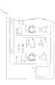
以下、本発明の好ましい実施形態について、添付図面を参照して説明する。図1は、本発明によるハウリング装置1の電気的構成を示すブロック図である。図1に示すように、ハウリング防止装置1は、CPU2と、そのCPU2により実行されるプログラムを記憶するROM3と、RAM4と、操作パネル5と、DSP9がバスを介して相互に接続され、DSP9には、入力側に、マイクロフォン6と、マイクロフォンフォン用の増幅器7と、A/D変換器8が接続され、出力側にD/A変換器10と、そのD/A変換器10により変換されたアナログ信号を増幅する増幅器11とスピーカ12とが備えられている。
Hereinafter, preferred embodiments of the present invention will be described with reference to the accompanying drawings. FIG. 1 is a block diagram showing an electrical configuration of a
図2は、操作パネル5の詳細を示す操作パネル図であって、操作パネル2には、ハウリング防止装置1の電源をオンオフする電源スイッチ5aと、各チャネルに対応して複数の操作子が備えられている。ここでは、チャネル1に備えられている操作子について説明し、他のチャネルの操作子については、説明を省略する。
FIG. 2 is an operation panel diagram showing details of the
インプットセレクトスイッチ5bは、チャネル1に接続された入力機器がマイクレベルを出力するものであるか、ラインレベルを出力するものであるかを設定するスイッチであり、マイクレベルを選択するとLED1が、ラインレベルを選択するとLED2が点灯される。
The
リバーブ・ディレイ設定ツマミ5cは、このチャネルに入力される音声に付与されるリバーブまたはディレイのいずれかの効果の深さを設定するものである。ツマミが左半分の位置に設定された場合は、リバーブ深さを、右半分の位置に設定された場合は、ディレイの深さを設定する。ボリュームツマミ5dは、このチャネルに入力される音声の音量を調整するツマミである。
The reverb / delay setting knob 5c sets the depth of the effect of either reverberation or delay added to the sound input to this channel. When the knob is set to the left half position, the reverb depth is set. When the knob is set to the right half position, the delay depth is set. The
アンチフィードバックスイッチ5eは、このチャネルのアンチフィードバック機能(ハウリング防止)を有効とするか無効とするかを切り替えるスイッチであり、アンチフィードバック機能を有効として設定した場合に、LED3が点灯される。アンチフィードバック機能を有効とするように設定された場合は、入力された音声信号は、後述するノッチフィルタ部23(図3参照)により所定の周波数のレベルが低下される。
The
スキャンスイッチ5fは、アンチフィードバック機能が有効である場合に、ノッチフィルタ部23の周波数などの設定を行うために、内蔵されている音源を起動するスイッチである。音源が、発振を開始しノッチフィルタの設定が終了するまでの間、LED4は、点滅を行う。
The
図3は、DSP9の機能ブロック図である。なお、リバーブやディレイなどの効果に関する機能については、その機能を省略している。A/D変換器8により所定のサンプリング周波数(例えば48kHz)で変換されたデジタル振幅値は、帯域分割部21およびノッチフィルタ部23に入力される。
FIG. 3 is a functional block diagram of the DSP 9. Note that functions relating to effects such as reverb and delay are omitted. The digital amplitude value converted at a predetermined sampling frequency (for example, 48 kHz) by the A /
帯域分割部21は、入力される音声の帯域である20Hzから20kHzまでの範囲を50の帯域に分割するバンドパスフィルタにより構成され、各分割された帯域毎にピーク検出部22により、レベルのピーク値が検出される。ピーク検出部20の各帯域に対応するピーク検出回路は、測定を開始する時点でピーク値が0に設定され、その後入力されたレベルの最も大きい値を保持するものである。
The
ピーク検出部22により検出された各帯域のピーク値に応じて、ハウリングが起こる蓋然性が高い周波数が検出され、その検出された周波数に対してノッチフィルタ部23が設定される。いずれの周波数が選択されるかについては、その詳細を後述する。
According to the peak value of each band detected by the
DSP9には、音源部24が備えられ、スキャンスイッチ5fが操作された場合に、可聴周波数帯域をカバーする50Hzから24kHz弱までの周波数成分の楽音を順次均一なレベルで発生する。音源部24は、波形メモリ24aに200Hzのサイン波が、1周期分、所定のサンプリング周波数Fs(48kHzとする)で標本化され、その振幅値がアドレス順に記憶されている。
The DSP 9 is provided with a
振幅値読み出し部24bは、波形メモリ24aから、記憶された振幅値を順次読出す処理を行うもので、振幅値を1つずつ読み出したり、複数個おきに読み出す機能を有している。振幅値が1つずつ読み出された場合は、その読み出された波形の音高は、200Hzであり、2つおきに読出された場合は、その読出された波形の音高は600Hzとなる。同様に、4つおきに読出された場合の波形の音高は、1000Hzであり、6つおきに読出された場合の波形の音高は1400Hzである。
The amplitude value reading unit 24b performs a process of sequentially reading stored amplitude values from the
この振幅値読み出し部24bは、上記サンプリング周波数により規定される周期SPのうち、1回、振幅値を読み出して出力するとつぎの3回の周期では、標本点追加部24cが、振幅値が0である標本点を出力する処理を行うように構成されている。 When the amplitude value reading unit 24b reads and outputs the amplitude value once in the period SP defined by the sampling frequency, the sampling point adding unit 24c sets the amplitude value to 0 in the next three cycles. A process for outputting a certain sample point is performed.
音源部24の出力と、ノッチフィルタ部23の出力は、スイッチSW1の入力1および2に接続され、いずれかが選択されてDSP9からD/A変換器10へ出力される。
The output of the
スキャンスイッチ5fが操作された場合は、SW1は、入力1に接続され、音源部24により発生された音声が出力され、この状態において、マイクロフォン6から入力された音声が帯域分割部21により帯域分割され、ピーク検出部22により帯域の毎のピーク値が検出されてノッチフィルタ部23が設定される。
When the
ノッチフィルタ部23の設定が完了すると、SW1は、入力2に接続され、ノッチフィルタ部23よりハウリングが起きる蓋然性が高い周波数のレベルが低下され、ハウリングの発生が抑制される。
When the setting of the
図4は、ハウリング防止装置1を設置する空間において、可聴周波数帯域全域で均一なレベルの音声を発生した場合の、その空間での周波数特性を模式的に示す図である。図4(a)は、マイクロフォンの近辺に人が存在する場合(実線)と、人が存在しない場合(一点鎖線)とにおける周波数特性を示すグラフで、いずれも横軸を周波数とし、縦軸をレベルとして示している。
FIG. 4 is a diagram schematically showing frequency characteristics in the space when sound having a uniform level is generated in the entire audible frequency band in the space in which the
この図が示すように、マイクロフォンの近辺に人が存在する場合の周波数特性は、マイクロフォンの近辺に人が存在しない場合の周波数特性を、周波数が高いほどレベルを大きくした周波数特性に近似している。したがって、マイクロフォンの近辺に人が存在している場合の周波数特性およびマイクロフォンの近辺に人が存在していない場合の周波数特性から緩やかなレベル変化を除去した周波数特性は、ほぼ同一であることが分かる。 As shown in this figure, the frequency characteristic when there is a person near the microphone approximates the frequency characteristic when there is no person near the microphone to the frequency characteristic in which the level is increased as the frequency is higher. . Therefore, it can be seen that the frequency characteristic when a person is present near the microphone and the frequency characteristic obtained by removing a gradual level change from the frequency characteristic when a person is not present near the microphone are substantially the same. .
図4(b)は、図4(a)に示すマイクロフォンの近辺に人が存在している場合の周波数特性またはマイクロフォンの近辺に人が存在していない場合の周波数特性から緩やかなレベル変化を除去した周波数特性である。この周波数特性は、図4(a)に示す周波数特性を、周波数に対応するレベル値を数列として、ハイパスフィルタを通すことにより得られるものである。具体的な方法としては、周波数に対し、緩やかなレベル変化を移動平均として演算により取得し、レベル値から移動平均により得られたレベル値を差し引くことにより得ることができる。 FIG. 4B removes a gradual level change from the frequency characteristics when a person is present near the microphone shown in FIG. 4A or the frequency characteristics when a person is not present near the microphone. Frequency characteristics. This frequency characteristic is obtained by passing the frequency characteristic shown in FIG. 4A through a high-pass filter using the level value corresponding to the frequency as a sequence. As a specific method, it can be obtained by calculating a gradual level change with respect to the frequency as a moving average, and subtracting the level value obtained by the moving average from the level value.
図5は、音源部24が発生する音声の波形を示す波形図である。図5(a)は、音源部24に備えられた波形メモリ24aに記憶された波形の一例を示すもので、横軸を時間tとし、縦軸を波形の振幅値として示し、所定の周波数特性を有する1周期の波形を所定のサンプリング周期SPでサンプリングし、一連の振幅値a,b,c・・・を示すものである。波形メモリ24aには、これらの振幅値がアドレス順に記憶されている。
FIG. 5 is a waveform diagram showing the waveform of the sound generated by the
図5(b)は、この波形メモリ24aから振幅値読み出し部24bにより振幅値が順次読出され、標本点追加部24cにより隣り合う振幅値の間に複数の振幅値0が所定のサンプリング周期SPを複数等分したサンプリング周期で挿入された波形を示すものである。この実施形態では、3つの振幅値0の標本点が挿入された場合を示している。
In FIG. 5B, amplitude values are sequentially read out from the
図5(c)は、このようにして形成された波形と元の波形の周波数特性を示す図である。この図において元波形のスペクトル(周波数fo)として示すスペクトルが、波形メモリに記憶されている波形をサンプリング周期SPで順次形成した場合のスペクトルであり、この波形の各標本点の間に同一のサンプリング周期で、3点の0振幅点を追加した波形(以下、ゼロ点挿入波形と称す)のスペクトルは、元波形のスペクトルの周波数foの1/4の周波数(fo/4)とそのエイリアスのスペクトルである。 FIG. 5C is a diagram showing the frequency characteristics of the waveform thus formed and the original waveform. In this figure, the spectrum shown as the spectrum of the original waveform (frequency fo) is a spectrum when the waveforms stored in the waveform memory are sequentially formed at the sampling period SP, and the same sampling is performed between the sampling points of this waveform. The spectrum of a waveform (hereinafter referred to as a zero-point insertion waveform) with three zero amplitude points added in the period is a frequency (fo / 4) of ¼ of the frequency fo of the spectrum of the original waveform and its alias spectrum. It is.
図に示されるように、ゼロ点挿入波形のスペクトルの周波数は、0〜(Fs/8)、(Fs/8)〜(Fs/4)、(Fs/4)〜(3Fs/8)、(3Fs/8)〜(Fs/2)の各帯域にそれぞれ1つずつ発生し、これらは(Fs/8)軸および(Fs/4)軸に対して対称に発生する。すなわち、これらのスペクトルの周波数は、0〜(Fs/8)の範囲では、fo/4であり、(Fs/8)〜(Fs/4)の範囲では、(Fs/4)−(fo/4)であり、(Fs/4)〜(3Fs/8)の範囲では、(Fs/4)+(fo/4)であり、(3Fs/8)〜(Fs/2)の範囲では、(Fs/2)−(fo/4)である。 As shown in the figure, the frequency of the spectrum of the zero point insertion waveform is 0 to (Fs / 8), (Fs / 8) to (Fs / 4), (Fs / 4) to (3Fs / 8), ( One is generated in each band of 3Fs / 8) to (Fs / 2), and these are generated symmetrically with respect to the (Fs / 8) axis and the (Fs / 4) axis. That is, the frequency of these spectra is fo / 4 in the range of 0 to (Fs / 8), and (Fs / 4) − (fo / in the range of (Fs / 8) to (Fs / 4). 4), and in the range of (Fs / 4) to (3Fs / 8), it is (Fs / 4) + (fo / 4), and in the range of (3Fs / 8) to (Fs / 2), ( Fs / 2)-(fo / 4).
従って、元波形から振幅値読み出し部24bにより読み出された波形のスペクトルが200Hzから(Fs/2)の範囲で変化すると、ゼロ点挿入波形のスペクトルは上記4つの帯域においても同様に変化する。 Therefore, when the spectrum of the waveform read from the original waveform by the amplitude value reading unit 24b changes in the range of 200 Hz to (Fs / 2), the spectrum of the zero point insertion waveform also changes in the above four bands.
このようにすると、元の波形のスペクトルが特定の周波数に集中しているのに対して、新たに形成される波形のスペクトルは、エイリアスにより上記した4つの周波数帯域に分散するので、和音のような効果となり、人間にとり刺激感の少ない聞きやすい楽音となる。 In this way, the spectrum of the original waveform is concentrated at a specific frequency, whereas the spectrum of the newly formed waveform is dispersed in the above four frequency bands due to aliasing. The effect is easy to hear and less irritating for humans.
また、元波形の音高を上記のように400Hzおきに発生すると、各帯域においては100Hzおきにスペクトルが発生する。従って、少ない音高変化で、多数の異なる周波数の楽音を発生することができる。 When the pitch of the original waveform is generated every 400 Hz as described above, a spectrum is generated every 100 Hz in each band. Therefore, a large number of different frequencies can be generated with a small pitch change.
図6は、DSP9におけるフィルタの設定処理を示すフローチャートである。このフィルタの設定処理は、スキャンスイッチ5fが操作された場合に起動される処理であり、CPU2が、スキャンスイッチ5fが操作されたか否かを検出し、スキャンスイッチ5fが操作されたことを検出した場合は、DSP9にこのフィルタ処理を実行するように指示し、DSP9が実行を開始する。まず、ピーク検出部22の各帯域毎に設けられているピーク検出回路のピーク値を0に設定する(S1)。
FIG. 6 is a flowchart showing filter setting processing in the DSP 9. This filter setting process is started when the
次に、波形メモリ24aから読出す間隔を1に設定する(S2)。このことにより振幅値読み出し部24bは、波形メモリ24aに記憶された200Hzのサイン波の振幅値を順次読み出す。標本点追加部24cは、読み出した振幅値の次の3つのサンプリング周期SPに、振幅値が0である標本点を挿入する。このことにより、形成されるゼロ点挿入波形は、50Hzのスペクトルを含むものとなる。こうして音源部が音声の発生を開始し、1秒間同一の音高で楽音を発生する。
Next, the interval for reading from the
次に読出すアドレスを2つおき(振幅値を2つ読み飛ばす)とする(S3)。このことにより波形メモリから読出される元波形の音高は、600Hzとなる。この場合も同様に読み出した振幅値の次の3つのサンプリング周期は、振幅値が0である標本点を挿入する。このことにより、ゼロ点挿入波形は、150Hzのスペクトルを含むものとなる。 Next, every two addresses to be read out are skipped (two amplitude values are skipped) (S3). As a result, the pitch of the original waveform read from the waveform memory is 600 Hz. In this case as well, sample points with an amplitude value of 0 are inserted in the next three sampling periods of the read amplitude value. As a result, the zero point insertion waveform includes a spectrum of 150 Hz.
同様にこの音高で1秒間音声を発生すると、次に読み出しアドレスを4つおき(振幅値を4つ読み飛ばす)とすると、読出される元波形の音高は、1000Hzとなり、ゼロ点波形は、250Hzのスペクトルを含むものとなる。以降、このS3の処理において、6つおき、8つおきというように、順次偶数の振幅値を読み飛ばして、元波形を形成する。このようにして音高を順次高くすると、60回で読出される元波形の音高は、23.8kHzとなり可聴帯域を十分にカバーする楽音を発生することができる(S4)。 Similarly, if sound is generated at this pitch for 1 second, then every four read addresses (4 amplitude values skipped), the pitch of the read original waveform is 1000 Hz, and the zero point waveform is , Including a spectrum of 250 Hz. Thereafter, in the process of S3, the original waveform is formed by skipping even-numbered amplitude values sequentially, such as every 6th and every 8th. When the pitch is sequentially increased in this way, the pitch of the original waveform read out 60 times becomes 23.8 kHz, and a musical tone that sufficiently covers the audible band can be generated (S4).
可聴帯域全域の楽音の発生を終了した場合は(S4:Yes)、つぎに、空間での音声の残響が安定するまでの時間を待機する(S5)。この残響が安定する時間は、空間の大きさによって異なるが、数秒程度の長さである。この間、帯域分割部21は、常時入力される音声の帯域を分割し、ピーク検出部22は、帯域毎の入力音声のレベルのピーク値を検出し、保持する。
When the generation of the musical sound in the entire audible band is finished (S4: Yes), the next time until the sound reverberation in the space is stabilized is waited (S5). The time during which the reverberation stabilizes is about several seconds, although it varies depending on the size of the space. During this time, the
このことにより、各帯域毎のピーク値が取得される。次に、この取得されたピーク値について、移動平均値を順次求め、ピーク値から差し引く。帯域分割部21により分割されたそれぞれの帯域のピーク値を、P1〜P50とすると、N番目のピーク値PNについては、P(N−4)からP(N+4)の9個のピーク値を加算し、その総和を9で除して平均値を求め、PNからその平均値を差し引いて補正したPN値とする(S6)。
As a result, the peak value for each band is acquired. Next, for the acquired peak value, a moving average value is sequentially obtained and subtracted from the peak value. When the peak values of the respective bands divided by the
このようにして演算を行うことにより、ピーク値の緩やかな変化を除去したピーク値が得られ、マイクロフォンに人が近接しているいないに係わらない帯域毎のレベルが得られる。よって、このようにして得られた補正したピーク値の大きい周波数にノッチフィルタの中心周波数を設定する(S7)。 By performing the calculation in this way, a peak value from which a gradual change of the peak value is removed is obtained, and a level for each band is obtained regardless of whether a person is close to the microphone. Therefore, the center frequency of the notch filter is set to a frequency having a large corrected peak value obtained in this way (S7).
一般に、マイクロフォンの近辺に人が存在している場合は、人が存在していない場合に比べ、周波数特性の高音域が持ち上がる傾向にある。従って、マイクロフォンの近辺に人が存在しない状態で検出した周波数特性の高音域を持ち上げることにより、マイクロフォンの近辺に人が存在する場合の周波数特性を得ることができる。よって、マイクロフォンの近辺に人が存在しない状態での周波数特性の高音域を持ち上げることにより、周波数特性の緩やかな変化を除去するようにしてもよい。 Generally, when a person is present in the vicinity of a microphone, the high frequency range of the frequency characteristic tends to be higher than when no person is present. Therefore, by raising the high frequency range of the frequency characteristic detected in the state where no person is present near the microphone, it is possible to obtain the frequency characteristic when a person is present near the microphone. Therefore, a gentle change in the frequency characteristic may be removed by raising the high frequency range of the frequency characteristic when no person is present near the microphone.
以上説明したように、本発明のハウリング防止装置によれば、振幅値を有する標本点の次に、所定のサンプリング周期で振幅値が0である標本点が複数挿入されるので、基音となるスペクトルと倍音とが形成され、人にとって耳障りではない試験音声が形成される。 As described above, according to the howling prevention apparatus of the present invention, since a plurality of sample points having an amplitude value of 0 in a predetermined sampling period are inserted after a sample point having an amplitude value, a spectrum serving as a fundamental tone And overtones are formed, and test sounds that are not harsh to humans are formed.
また、波形メモリには、振幅値を有する波形が記憶され、振幅値が0である標本点は、標本点追加部により挿入されるので、波形メモリは、少ない容量で波形を記憶することができる。 In addition, since the waveform memory stores a waveform having an amplitude value, and a sample point having an amplitude value of 0 is inserted by the sample point adding unit, the waveform memory can store the waveform with a small capacity. .
以上、実施形態に基づき本発明を説明したが、本発明は上述した実施形態に何ら限定されるものではなく、本発明の趣旨を逸脱しない範囲内で種々の改良変更が可能であることは容易に推察できるものである。 Although the present invention has been described based on the embodiments, the present invention is not limited to the above-described embodiments, and various improvements and modifications can be easily made without departing from the spirit of the present invention. Can be inferred.
例えば、上記実施形態では、音源は、100Hz毎に音高を高くして順次音声を発生するものとしたが、音高を変化させる幅を100セントまたは200セントなどのように対数的に一定間隔で変化するようにしてもよい。 For example, in the above-described embodiment, the sound source is assumed to generate sound sequentially by increasing the pitch every 100 Hz. However, the range in which the sound pitch is changed is logarithmically constant, such as 100 cents or 200 cents. You may make it change with.
また、上記実施形態では、入力した音声を複数のバンドパスフィルタに通し、各帯域ののレベルを検出することにより周波数特性を検出するものとしたが、入力した音声をFFTなどを用いることによりフーリエ変換を行って検出するものとしてもよい。 In the above embodiment, the input sound is passed through a plurality of bandpass filters, and the frequency characteristics are detected by detecting the level of each band. However, the input sound is Fourier-transformed by using FFT or the like. It is good also as what detects by performing conversion.
1 ハウリング防止装置
6 マイクロフォン(入力手段)
9 DSP
12 スピーカ(出力手段)
21 帯域分割部
22 ピーク検出部
23 ノッチフィルタ部(フィルタ手段) 24 音源
24a 波形メモリ(波形記憶手段)
24b 振幅値読み出し部(振幅値読み出し手段)
24c 標本点追加部(標本点追加手段)
1 Howling prevention device 6 Microphone (input means)
9 DSP
12 Speaker (output means)
21
24b Amplitude value reading unit (amplitude value reading means)
24c Sample point adding unit (sample point adding means)
Claims (3)
その入力手段により入力された音声信号の周波数特性を検出し、その検出された周波数特性に応じて前記入力手段により入力された音声信号の特定の周波数成分の出力レベルを低下させるフィルタ手段とを備えたハウリング防止装置において、
所定のサンプリング周期でサンプリングした一連の振幅値を有する標本点と、その隣り合う振幅値を有する標本点の間に、前記所定のサンプリング周期を複数等分したサンプリング周期で、振幅値を0とする標本点とを有する音声信号を発生する音源手段と、
その音源手段により発生された音声信号を空間に出力する出力手段とを有し、
前記入力手段は、前記出力手段により出力された音声信号を入力するものであることを特徴とするハウリング防止装置。 An input means for inputting an audio signal;
Filter means for detecting a frequency characteristic of an audio signal input by the input means and reducing an output level of a specific frequency component of the audio signal input by the input means in accordance with the detected frequency characteristic; In a howling prevention device,
A sample point having a series of amplitude values sampled at a predetermined sampling period, during sample points having an amplitude value adjacent its, the predetermined sampling cycle in multiple equally divided sampling period, the amplitude value 0 Sound source means for generating an audio signal having a sample point;
Output means for outputting to the space the audio signal generated by the sound source means,
The howling prevention apparatus according to claim 1, wherein the input means inputs the audio signal output by the output means.
前記所定のサンプリング周期で所定の波形を標本化した一連の振幅値を記憶する波形記憶手段と、
その波形記憶手段から順次振幅値を読出す振幅値読み出し手段と、
その振幅値読み出し手段が読み出した隣り合う振幅値の間に、前記所定のサンプリング周期を複数等分したサンプリング周期で振幅値が0とする標本点を追加する標本点追加手段とを備えていることを特徴とする請求項1記載のハウリング防止装置。 The sound source means is
A waveform storage means for storing a set of amplitude values that have been sampled a predetermined waveform at the predetermined sampling period,
Amplitude value reading means for sequentially reading amplitude values from the waveform storage means;
Sample point adding means for adding a sample point having an amplitude value of 0 in a sampling period obtained by dividing the predetermined sampling period into a plurality of equal parts between adjacent amplitude values read by the amplitude value reading means. The howling prevention apparatus according to claim 1 .
前記音源手段は、前記振幅値読み出し手段が読出す波形の音高を変更して読出すように制御する音高変更手段を備えていることを特徴とする請求項2記載のハウリング防止装置。 The waveform storage means stores a waveform of an audio signal in a predetermined frequency band,
3. The howling prevention apparatus according to claim 2, wherein the sound source means includes a pitch change means for controlling to change and read the pitch of the waveform read by the amplitude value reading means.
Priority Applications (2)
| Application Number | Priority Date | Filing Date | Title |
|---|---|---|---|
| JP2005108462A JP4573689B2 (en) | 2005-04-05 | 2005-04-05 | Howling prevention device |
| US11/393,505 US7840014B2 (en) | 2005-04-05 | 2006-03-29 | Sound apparatus with howling prevention function |
Applications Claiming Priority (1)
| Application Number | Priority Date | Filing Date | Title |
|---|---|---|---|
| JP2005108462A JP4573689B2 (en) | 2005-04-05 | 2005-04-05 | Howling prevention device |
Publications (3)
| Publication Number | Publication Date |
|---|---|
| JP2006287849A JP2006287849A (en) | 2006-10-19 |
| JP2006287849A5 JP2006287849A5 (en) | 2008-05-22 |
| JP4573689B2 true JP4573689B2 (en) | 2010-11-04 |
Family
ID=37409234
Family Applications (1)
| Application Number | Title | Priority Date | Filing Date |
|---|---|---|---|
| JP2005108462A Expired - Fee Related JP4573689B2 (en) | 2005-04-05 | 2005-04-05 | Howling prevention device |
Country Status (1)
| Country | Link |
|---|---|
| JP (1) | JP4573689B2 (en) |
Families Citing this family (2)
| Publication number | Priority date | Publication date | Assignee | Title |
|---|---|---|---|---|
| JP4697267B2 (en) | 2008-07-01 | 2011-06-08 | ソニー株式会社 | Howling detection apparatus and howling detection method |
| CN113271386B (en) * | 2021-05-14 | 2023-03-31 | 杭州网易智企科技有限公司 | Howling detection method and device, storage medium and electronic equipment |
Citations (4)
| Publication number | Priority date | Publication date | Assignee | Title |
|---|---|---|---|---|
| JPH06236188A (en) * | 1992-09-30 | 1994-08-23 | Sharp Corp | Active muffler for periodic sound |
| JPH0965497A (en) * | 1995-08-28 | 1997-03-07 | Victor Co Of Japan Ltd | Sound image localization device |
| JP2003195859A (en) * | 2001-12-27 | 2003-07-09 | Yamaha Corp | Electronic musical sound generating device and signal processing characteristic adjusting method |
| JP2004239927A (en) * | 2002-12-09 | 2004-08-26 | Toa Corp | Resonance frequency detection method, resonance frequency selection method, and resonance frequency detection device |
-
2005
- 2005-04-05 JP JP2005108462A patent/JP4573689B2/en not_active Expired - Fee Related
Patent Citations (4)
| Publication number | Priority date | Publication date | Assignee | Title |
|---|---|---|---|---|
| JPH06236188A (en) * | 1992-09-30 | 1994-08-23 | Sharp Corp | Active muffler for periodic sound |
| JPH0965497A (en) * | 1995-08-28 | 1997-03-07 | Victor Co Of Japan Ltd | Sound image localization device |
| JP2003195859A (en) * | 2001-12-27 | 2003-07-09 | Yamaha Corp | Electronic musical sound generating device and signal processing characteristic adjusting method |
| JP2004239927A (en) * | 2002-12-09 | 2004-08-26 | Toa Corp | Resonance frequency detection method, resonance frequency selection method, and resonance frequency detection device |
Also Published As
| Publication number | Publication date |
|---|---|
| JP2006287849A (en) | 2006-10-19 |
Similar Documents
| Publication | Publication Date | Title |
|---|---|---|
| KR101201442B1 (en) | Measuring apparatus, measuring method, and program therefor | |
| JP4915773B2 (en) | Transfer characteristic measuring method and apparatus | |
| JP4672474B2 (en) | Automatic musical transcription device and program | |
| US7840014B2 (en) | Sound apparatus with howling prevention function | |
| EP2372693B1 (en) | Signal processing device and stringed instrument | |
| CN105491495B (en) | Deterministic sequence based feedback estimation | |
| JP2002015522A (en) | Audio band extending device and audio band extension method | |
| WO2018179506A1 (en) | Audio device and computer readable program | |
| JP4573689B2 (en) | Howling prevention device | |
| JP4985570B2 (en) | Digital acoustic signal processing method and processing apparatus | |
| JP5035386B2 (en) | Measuring method, measuring device, program | |
| JP2008072600A (en) | Acoustic signal processing apparatus, acoustic signal processing program, and acoustic signal processing method | |
| JP5377167B2 (en) | Scream detection device and scream detection method | |
| JP2013239973A (en) | Overtone additional device of sound signal | |
| JP2006287851A (en) | Howl preventing device | |
| JP2006313953A (en) | Automatic sound field correction system, automatic sound field correction method, and sound field measurement apparatus | |
| JPH11202896A (en) | Method and device for emphasizing voice high-frequency | |
| KR970004178B1 (en) | Audio echo sound adding device | |
| JP2011217067A (en) | Sound signal output control device | |
| JP2009069181A (en) | Sound field correction apparatus | |
| JP4432951B2 (en) | Musical sound generator and electronic musical instrument | |
| JP2007163586A (en) | Music genre determination apparatus and game machine provided with it | |
| JP2005024997A (en) | Stringed instrument and effect device | |
| KR100228392B1 (en) | Adding apparatus of echo sound for frequency variable | |
| JP2023101228A (en) | Sound conversion device |
Legal Events
| Date | Code | Title | Description |
|---|---|---|---|
| RD02 | Notification of acceptance of power of attorney |
Free format text: JAPANESE INTERMEDIATE CODE: A7422 Effective date: 20061109 |
|
| A521 | Written amendment |
Free format text: JAPANESE INTERMEDIATE CODE: A523 Effective date: 20080403 |
|
| A621 | Written request for application examination |
Free format text: JAPANESE INTERMEDIATE CODE: A621 Effective date: 20080403 |
|
| A977 | Report on retrieval |
Free format text: JAPANESE INTERMEDIATE CODE: A971007 Effective date: 20100412 |
|
| A131 | Notification of reasons for refusal |
Free format text: JAPANESE INTERMEDIATE CODE: A131 Effective date: 20100420 |
|
| A521 | Written amendment |
Free format text: JAPANESE INTERMEDIATE CODE: A523 Effective date: 20100621 |
|
| TRDD | Decision of grant or rejection written | ||
| A01 | Written decision to grant a patent or to grant a registration (utility model) |
Free format text: JAPANESE INTERMEDIATE CODE: A01 Effective date: 20100817 |
|
| A01 | Written decision to grant a patent or to grant a registration (utility model) |
Free format text: JAPANESE INTERMEDIATE CODE: A01 |
|
| A61 | First payment of annual fees (during grant procedure) |
Free format text: JAPANESE INTERMEDIATE CODE: A61 Effective date: 20100817 |
|
| R150 | Certificate of patent or registration of utility model |
Free format text: JAPANESE INTERMEDIATE CODE: R150 |
|
| FPAY | Renewal fee payment (event date is renewal date of database) |
Free format text: PAYMENT UNTIL: 20130827 Year of fee payment: 3 |
|
| LAPS | Cancellation because of no payment of annual fees |