JP4573371B2 - Continuous coin washing machine - Google Patents
Continuous coin washing machine Download PDFInfo
- Publication number
- JP4573371B2 JP4573371B2 JP06662099A JP6662099A JP4573371B2 JP 4573371 B2 JP4573371 B2 JP 4573371B2 JP 06662099 A JP06662099 A JP 06662099A JP 6662099 A JP6662099 A JP 6662099A JP 4573371 B2 JP4573371 B2 JP 4573371B2
- Authority
- JP
- Japan
- Prior art keywords
- coins
- coin
- conveyor
- cleaning liquid
- rotating drum
- Prior art date
- Legal status (The legal status is an assumption and is not a legal conclusion. Google has not performed a legal analysis and makes no representation as to the accuracy of the status listed.)
- Expired - Lifetime
Links
Images


Description
【0001】
【発明の属する技術分野】
この発明は、ゲーム機等で用いられるコインを洗浄するコイン洗浄装置に関するものである。
【0002】
【従来の技術および発明が解決しようとする課題】
ゲーム機等で用いられるコインを洗浄するコイン洗浄装置としては、一度にコインを投入して洗浄するバッチ式洗浄装置と、コインを連続的に投入して洗浄する連続式洗浄装置とがある。
【0003】
前者は、異なるサイズのコインを同じ装置で洗浄できる利点があるが、洗浄槽からのコインの取り出し等のハンドリングに手間がかかる難点がある。後者はこれらのハンドリングの手間を解消するものとして、近年種々のタイプの洗浄装置が開発されている。従来の連続式洗浄装置は、洗浄や脱水、乾燥用等の容器や搬送部材に、コインのサイズに合致する凹部等のコイン保持部を設けてコインを連続的に送っているため、異なるサイズのコインをそのまま洗浄できない問題がある。したがって、異なるサイズのコインを洗浄するためには、複数の洗浄装置を準備するか、前記洗浄や脱水、乾燥用等の容器や搬送部材を交替する必要がある。
【0004】
上述したコイン洗浄装置では、通常、中性や弱アルカリ性の洗浄液が用いられ、これらの洗浄液には、洗浄効率を高めるため、アルミナ等を含有する研磨用チップを混入することが多い。前記連続式洗浄装置で研磨用チップを用いる場合は、研磨用チップを洗浄液とともに循環させるためのポンプ等を必要とし、また、洗浄後のコインと研磨用チップとを分離する必要もあるため、洗浄装置が複雑で大きくなる問題がある。
【0005】
そこで、この発明の課題は、シンプルでコンパクトな構成で、異なるサイズのコインもそのまま洗浄できる連続式コイン洗浄装置を提供することである。
【0006】
【課題を解決するための手段】
上記の課題を解決するために、この発明の連続式コイン洗浄装置は、洗浄されるコインが投入されるホッパと、供給端にホッパからのコインが供給され、内周面に設けられた螺旋状の案内羽根でコインを排出端に向けて連続的に送り出す横向きの回転ドラムと、この回転ドラムの少なくとも下部が浸漬される洗浄液槽と、前記回転ドラムの排出端から送り出されるコインを連続的にすくい上げる手段と、すくい上げられたコインを搬送する第1のコンベアと、搬送されたコインに付着する洗浄液を除去する絞りロールと、洗浄液を除去されたコインをコイン取り出し口に搬送する第2のコンベアとを備え、前記案内羽根が設けられた回転ドラムの内周面に研磨用ブラシを設けた構成を採用したのである。
【0007】
すなわち、ホッパから投入されたコインを、内周面に研磨用ブラシが設けられた横向きの回転ドラムの中に供給し、回転ドラムの下部で洗浄液に漬かるコインを螺旋状の案内羽根で排出端に送りながら、研磨用ブラシで研磨することにより、シンプルな構成でコインの洗浄効率を高めるようにしたのである。また、洗浄されたコインを連続的にすくい上げて絞りロールへ搬送し、コインに付着した洗浄液を除去するようにしたので、異なるサイズのコインも連続的に洗浄することができる。
【0008】
前記第1のコンベアの搬送路の途中に、搬送面上でコインの厚みよりもわずかに大きい隙間を形成するゲートを設けることにより、搬送されるコインをこのゲートで一層に整列し、絞りロールに供給されるコインの重なり合いをなくして、コインに付着する洗浄液を確実に除去することができる。
【0009】
前記コンベアの搬送路を上向きに傾斜させ、その搬送面にコインの外径よりも小さい複数の水落とし孔を設けることにより、絞りロールに供給される前のコインを水切りし、絞りロールでの脱水効率を高めることができる。また、水落とし孔からは搬送面上の洗浄液も落下し、搬送面上に洗浄液が溜まることもないので、コインが搬送面を滑り落ちるのを防止することもできる。
【0010】
前記第2のコンベアの搬送路に温風を供給する手段を設けることにより、別の乾燥ボックス等を不要とし、かつ効率よくコインを仕上げ乾燥することができる。
【0011】
前記第1および第2のコンベアの少なくともいずれか一方のコンベアの搬送面上に、コインを上方から落とし込んで供給し、前記コンベアの搬送面に接触して従動回転する回転ローラを、前記コイン落下部位の搬送面の供給端側を覆って、搬送面の幅方向と平行に設けることにより、上方から落下するコインがコンベアの供給端から転げ落ちるのを防止するとともに、回転ローラに凭れ掛かるコインを搬送面上へスムーズに送り出すことができる。
【0012】
前記第1および第2のコンベアの少なくともいずれか一方のコンベアの搬送面上に、コインを上方から落とし込んで供給し、このコイン落下部位の搬送面の両側を覆う壁を設け、この壁の搬送面直上の内側面を、概ねコインの外径の半分よりも大きい高さに渡って、オーバハングして形成することにより、上方から落下するコインがコンベアの側端から転げ落ちるのを防止するとともに、搬送面両側の壁に凭れ掛かるコインを搬送面上に転倒させて、コインが壁に凭れて搬送面上で転動しながら滞留するのを防止することができる。
【0013】
前記第1および第2のコンベアの少なくともいずれか一方のコンベアの搬送路を、上向きに20°以上傾斜させて形成し、その搬送面に沿って、概ねコインの外径の半分よりも大きいピッチで突起を設けることにより、搬送路の急傾斜でコンベアの排出端を高い位置に設定して、コインの洗浄装置からの取り出し口を高い位置に設け、コインの取り出しを容易にすることができる。また、搬送路を急傾斜とすることにより、コンベアの専有面積を小さくして、洗浄装置をコンパクトな設計とすることもできる。搬送路の傾斜が20°以上になると、コインが搬送面上を滑り落ちることがあるので、この滑り落ちを前記突起で止めて、急傾斜の搬送路でもコインをスムーズに搬送することができる。
【0014】
【発明の実施の形態】
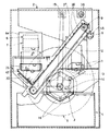
以下、図1乃至図8に基づき、この発明の実施形態を説明する。図1はコイン洗浄装置の正面図、図2は側面図、図3は、コイン1の流れに関係する部分のみを示す斜視図である。
【0015】
このコイン洗浄装置は、コイン1の投入用ホッパ2と、ホッパ2からのコイン1が供給される横向き六角筒状の回転ドラム3と、回転ドラム3の下部が浸漬される洗浄液槽4と、回転ドラム3から排出されるコイン1をすくい上げる籠車5と、籠車5ですくい上げられたコイン1を搬送する第1のコンベア6と、第1のコンベア6で搬送されたコイン1に付着する洗浄液を除去する絞りロール7と、洗浄液を除去されたコイン1を取り出し口8に搬送する第2のコンベア9とで基本的に構成されている。
【0016】
前記ホッパ2の底には、モータ10で駆動される回転羽根11が取り付けられ、ホッパ2に投入されたコイン1をこの回転羽根11で放出口12にかき上げて落下させている。放出口12から落下するコイン1は、シュート13、14を通って回転ドラム3の供給端に送り込まれる。
【0017】
前記回転ドラム3はモータ15によりチェーン駆動され、図4に示すように、その内周面には螺旋状の案内羽根16が設けられ、案内羽根16の間には合成繊維製のブラシ17が貼付されている。コイン1は、洗浄液に漬かった回転ドラム3の下部を転がりながら洗浄されるとともに、ブラシ17で表面の汚れ付着物を研磨除去されて、案内羽根16で連続的に排出端へ送られ、排出端の下方に取り付けられたシュート18から籠車5の中に落下する。コイン1の表面から除去された汚れ付着物は、回転ドラム3の排出端側に設けられた多数の小孔19から洗浄液槽4中に排出される。なお、回転ドラム3の排出端はラッパ状に拡径され、コイン1がシュート18へ排出され易くなっている。
【0018】
前記籠車5は、回転ドラム3の排出端に近接して配置され、歯車20で回転ドラム3の軸から回転力を伝達されている。この籠車5には、両端に内向きの鍔21が設けられ、その内周面には周方向に一定間隔で柵22が取り付けられており、その円筒面と柵22には、それぞれ水切り用の窓23、24が開けられている。籠車5の回転上昇側には、図5に示すように、籠車5の上側半分の内周面に沿って円弧状の案内板25が配置されており、前記シュート18から籠車5の中に落下したコイン1は、籠車5の回転に伴って柵22に載せられて持ち上げられ、籠車5の底から90度を越えた位置で案内板25の外周面上へ移動し、この外周面に沿って柵22の先端で案内板25の上端までかき上げられる。案内板25の上端からかき出されたコイン1は、その下方に取り付けられたシュート26から第1のコンベア6上に落下する。
【0019】
前記第1のコンベア6はモータ27で駆動され、その搬送路28の途中には、搬送面との間でコイン1の厚みよりもわずかに大きい隙間を形成する2つのゲート29が設けられている。搬送面上で重なり合ったコイン1は、これらのゲート29で一層に整列されて搬送され、第1のコンベア6の排出端下方に配置された絞りロール7に落下する。なお、ゲート29の数は1つでもよい。
【0020】
前記搬送路28は上向きに傾斜され、搬送路28の下端側には、図6(a)、(b)に示すように、搬送面に接触して従動回転するローラ30が搬送路28の幅方向に配列され、このローラ30の上方と搬送面の両側は、それぞれが衝立31、32で遮蔽されている。前記シュート26から落下するコイン1は、これらの衝立31、32で囲まれた部位の搬送面に着地し、ローラ30に凭れ掛かるコイン1は、ローラ30の回転で搬送面上に倒されて搬送される。また、搬送面には、コイン1の外径よりも小さい多数の水落とし孔33が設けられ、絞りロール7に供給されるコイン1と搬送面に付着する洗浄液を水切りするようになっており、絞りロール7での脱水効率を高めるとともに、コイン1が搬送面を滑り落ちるのを防止している。
【0021】
前記絞りロール7は吸水性と弾力性を有する酢酸スポンジ製で、互いに押圧されて水平に設置され、図1に示すように、一方の絞りロール7の回転軸に取り付けられた歯車34を介して、前記第1のコンベア6を駆動するモータ27で回転駆動される。第1のコンベア6で一層に整列されたコイン1は、一枚ずつ絞りロール7の間に落下し、その表面に付着した洗浄液が絞り取られる。洗浄液を絞り取られたコイン1は、シュート35を通って第2のコンベア9上に落下する。
【0022】
前記第2のコンベア9はモータ36で駆動され、その搬送路37は上向きに急傾斜している。図7に示すように、搬送面には一定のピッチで突起38が設けられており、搬送路37の下端側には、コイン1の落下防止用の衝立39が立てられている。衝立39の下端には、突起38を通過させるための切り込み40も設けられている。前記シュート35から搬送面上に落下するコイン1は、突起38に引っ掛かって急斜面の搬送路37を上方へ搬送され、衝立39に凭れ掛かるコイン1もこの突起38で搬送面上に送り出される。
【0023】
前記搬送路37の下端部の両側には、図8に示すように、断熱材41入りの壁42が設けられ、その内側面43の下部がオーバハングして形成されている。シュート35から落下して壁42に凭れ掛かるコイン1は、その姿勢のまま転動して搬送路37の下端部に滞留しないように、このオーバハングで内向きに倒される。
【0024】
前記搬送路37の上方には温風ヒータ44が配置されており、搬送路37に温風を供給して、わずかに湿気を有するコイン1の表面を乾燥させている。前記断熱材41は、第2のコンベア9のフレームの一部を形成する壁42が、温風ヒータ44で加熱されるのを防止するためのものである。完全に湿気を除去されたコイン1は、搬送路37の上端からシュート45に落下し、取り出し口8から外部に取り出される。
【0025】
【発明の効果】
以上のように、この発明のコイン洗浄装置は、ホッパから投入されたコインを、内周面に研磨用ブラシが設けられた横向きの回転ドラムの中に供給し、回転ドラムの下部で洗浄液に漬かるコインを螺旋状の案内羽根で排出端に送りながら、研磨用ブラシで研磨するようにしたので、シンプルな構成でコインの洗浄効率を高めることができる。また、第1のコンベアの搬送路の途中に、搬送面上でコインの厚みよりもわずかに大きい隙間を形成するゲートを設け、このゲートで搬送されるコインを一層に整列するようにしたので、絞りロールに供給されるコインの重なり合いを防止して、コインに付着する洗浄液を確実に除去することができる。さらに、第2のコンベアの搬送路に温風を供給する手段を設けたので、別の乾燥ボックス等なしで効率よくコインを仕上げ乾燥することができる。
【図面の簡単な説明】
【図1】コイン洗浄装置の実施形態を示す正面断面図
【図2】図1の側面断面図
【図3】図1の一部省略斜視図
【図4】aは図1の回転ドラムを示す一部切欠き正面図、bはaの要部拡大斜視図
【図5】図1の籠車の一部切欠き側面図
【図6】aは図1の第1のコンベアの下端部を示す外観斜視図、bはaのVI−VI線に沿った断面図
【図7】図1の第2のコンベアの下端部を示す外観斜視図
【図8】図7のVIII−VIII線に沿った断面図
【符号の説明】
1 コイン
2 ホッパ
3 回転ドラム
4 洗浄液槽
5 籠車
6 コンベア
7 絞りロール
8 取り出し口
9 コンベア
10 モータ
11 回転羽根
12 放出口
13、14 シュート
15 モータ
16 案内羽根
17 ブラシ
18 シュート
19 小孔
20 歯車
21 鍔
22 柵
23、24 窓
25 案内板
26 シュート
27 モータ
28 搬送路
29 ゲート
30 ローラ
31、32 衝立
33 孔
34 歯車
35 シュート
36 モータ
37 搬送路
38 突起
39 衝立
40 切り込み
41 断熱材
42 壁
43 内側面
44 温風ヒータ
45 シュート[0001]
BACKGROUND OF THE INVENTION
The present invention relates to a coin cleaning device for cleaning coins used in game machines and the like.
[0002]
[Background Art and Problems to be Solved by the Invention]
As a coin cleaning device for cleaning coins used in game machines and the like, there are a batch type cleaning device that inserts coins at a time for cleaning, and a continuous type cleaning device that continuously inputs coins for cleaning.
[0003]
The former has an advantage that coins of different sizes can be washed with the same apparatus, but there is a difficulty in handling handling such as taking out coins from the washing tank. In the latter case, various types of cleaning apparatuses have been developed in recent years as a means for eliminating the handling effort. The conventional continuous cleaning device is provided with a coin holding part such as a recess that matches the size of the coin on a container or transport member for cleaning, dehydration, drying, etc., and continuously sends coins. There is a problem that the coin cannot be washed as it is. Therefore, in order to wash coins of different sizes, it is necessary to prepare a plurality of washing devices, or to replace the washing and dehydrating and drying containers and transport members.
[0004]
In the above-described coin cleaning apparatus, a neutral or weak alkaline cleaning solution is usually used, and in order to improve cleaning efficiency, a polishing chip containing alumina or the like is often mixed in these cleaning solutions. When using polishing chips in the continuous cleaning apparatus, a pump or the like for circulating the polishing chips together with the cleaning liquid is required, and it is also necessary to separate the coins and polishing chips after cleaning. There is a problem that the apparatus becomes complicated and large.
[0005]
SUMMARY OF THE INVENTION An object of the present invention is to provide a continuous coin cleaning apparatus that can clean coins of different sizes as they are with a simple and compact configuration.
[0006]
[Means for Solving the Problems]
In order to solve the above-described problems, a continuous coin cleaning device of the present invention includes a hopper into which coins to be cleaned are inserted, and a spiral shape provided on the inner peripheral surface with coins supplied from the hopper at the supply end. The horizontal rotating drum that continuously feeds coins toward the discharge end with the guide vanes, the cleaning liquid tank in which at least the lower part of the rotary drum is immersed, and the coins fed from the discharge end of the rotary drum are continuously scooped up. Means, a first conveyor for transporting the scooped coins, a squeeze roll for removing the cleaning liquid adhering to the transported coins, and a second conveyor for transporting the coins from which the cleaning liquid has been removed to the coin take-out port. The structure which provided the brush for grinding | polishing in the internal peripheral surface of the rotating drum in which the said guide blade | wing was provided was employ | adopted.
[0007]
That is, the coins inserted from the hopper are supplied into a horizontal rotating drum provided with a polishing brush on the inner peripheral surface, and the coins immersed in the cleaning liquid at the lower part of the rotating drum are discharged to the discharge end with a spiral guide blade. By polishing with a polishing brush while feeding, the coin cleaning efficiency is improved with a simple configuration. In addition, since the washed coins are continuously picked up and conveyed to the squeeze roll, the washing liquid adhering to the coins is removed, so that coins of different sizes can be washed continuously.
[0008]
By providing a gate that forms a gap slightly larger than the thickness of the coin on the transport surface in the middle of the transport path of the first conveyor, the coins to be transported are further aligned by this gate, and the squeezing roll The overlapping of supplied coins can be eliminated, and the cleaning liquid adhering to the coins can be reliably removed.
[0009]
The conveyor path of the conveyor is inclined upward, and a plurality of water dropping holes smaller than the outer diameter of the coin are provided on the transport surface, so that the coin before being supplied to the squeeze roll is drained and dewatered by the squeeze roll. Efficiency can be increased. Further, since the cleaning liquid on the transport surface also falls from the water drop hole and the cleaning liquid does not accumulate on the transport surface, it is possible to prevent coins from sliding down the transport surface.
[0010]
By providing means for supplying warm air to the conveying path of the second conveyor, a separate drying box or the like is not required, and the coins can be finished and dried efficiently.
[0011]
A coin is dropped from above and supplied onto the conveying surface of at least one of the first and second conveyors, and a rotating roller that is driven to rotate in contact with the conveying surface of the conveyor is provided with the coin falling portion. By covering the supply end side of the transfer surface and providing it in parallel with the width direction of the transfer surface, coins falling from above are prevented from falling from the supply end of the conveyor, and the coins hanging on the rotating roller are transferred to the transfer surface. It can be sent out smoothly.
[0012]
A coin is dropped and supplied from above onto the conveyance surface of at least one of the first and second conveyors, and a wall is provided to cover both sides of the conveyance surface of the coin dropping portion. By forming the inner surface directly above overhanging over a height that is approximately larger than half the outer diameter of the coin, coins falling from above are prevented from falling from the side edge of the conveyor, and the conveying surface It is possible to prevent the coins leaning on the walls on both sides from falling on the transport surface, and preventing the coins from falling on the walls and staying while rolling on the transport surface.
[0013]
The conveying path of at least one of the first and second conveyors is formed so as to be inclined upward by 20 ° or more, and along the conveying surface, the pitch is substantially larger than half of the outer diameter of the coin. By providing the protrusion, the discharge end of the conveyor can be set at a high position due to the steep inclination of the transport path, and the coin outlet from the coin cleaning device can be provided at a high position, so that the coin can be easily taken out. Further, by making the transport path steeply inclined, the exclusive area of the conveyor can be reduced, and the cleaning device can be made compact. If the inclination of the conveyance path is 20 ° or more, coins may slide down on the conveyance surface, so that the sliding can be stopped by the protrusions and the coins can be smoothly conveyed even on the steeply inclined conveyance path.
[0014]
DETAILED DESCRIPTION OF THE INVENTION
Hereinafter, embodiments of the present invention will be described with reference to FIGS. FIG. 1 is a front view of a coin cleaning device, FIG. 2 is a side view, and FIG. 3 is a perspective view showing only a portion related to the flow of
[0015]
This coin cleaning device includes a coin-
[0016]
A
[0017]
The rotating
[0018]
The
[0019]
The
[0020]
The
[0021]
The squeezing
[0022]
The
[0023]
As shown in FIG. 8,
[0024]
A warm air heater 44 is disposed above the
[0025]
【The invention's effect】
As described above, in the coin cleaning device of the present invention, the coins inserted from the hopper are supplied into the horizontal rotating drum having the polishing brush provided on the inner peripheral surface, and immersed in the cleaning liquid at the lower portion of the rotating drum. Since the coin is polished with the polishing brush while being sent to the discharge end with the spiral guide blade, the coin cleaning efficiency can be enhanced with a simple configuration. In addition, since a gate that forms a gap slightly larger than the thickness of the coin on the transport surface is provided in the middle of the transport path of the first conveyor, the coins transported by this gate are further aligned. It is possible to prevent the coins supplied to the squeezing rolls from overlapping and to reliably remove the cleaning liquid adhering to the coins. Furthermore, since the means for supplying the warm air to the transport path of the second conveyor is provided, the coin can be efficiently finished and dried without a separate drying box or the like.
[Brief description of the drawings]
FIG. 1 is a front sectional view showing an embodiment of a coin washing device. FIG. 2 is a side sectional view of FIG. 1. FIG. 3 is a partially omitted perspective view of FIG. FIG. 5 is a partially cutaway front view of the main part of FIG. 1. FIG. 5 is a partially cutaway side view of the carriage of FIG. 1. FIG. 6a is a lower end of the first conveyor of FIG. FIG. 7 is a sectional view taken along line VI-VI in FIG. 7. FIG. 7 is a perspective view showing the lower end of the second conveyor in FIG. 1. FIG. 8 is taken along line VIII-VIII in FIG. Sectional view [Explanation of symbols]
DESCRIPTION OF
Claims (1)
Priority Applications (1)
| Application Number | Priority Date | Filing Date | Title |
|---|---|---|---|
| JP06662099A JP4573371B2 (en) | 1999-03-12 | 1999-03-12 | Continuous coin washing machine |
Applications Claiming Priority (1)
| Application Number | Priority Date | Filing Date | Title |
|---|---|---|---|
| JP06662099A JP4573371B2 (en) | 1999-03-12 | 1999-03-12 | Continuous coin washing machine |
Publications (2)
| Publication Number | Publication Date |
|---|---|
| JP2000259886A JP2000259886A (en) | 2000-09-22 |
| JP4573371B2 true JP4573371B2 (en) | 2010-11-04 |
Family
ID=13321126
Family Applications (1)
| Application Number | Title | Priority Date | Filing Date |
|---|---|---|---|
| JP06662099A Expired - Lifetime JP4573371B2 (en) | 1999-03-12 | 1999-03-12 | Continuous coin washing machine |
Country Status (1)
| Country | Link |
|---|---|
| JP (1) | JP4573371B2 (en) |
Families Citing this family (1)
| Publication number | Priority date | Publication date | Assignee | Title |
|---|---|---|---|---|
| CN113477562A (en) * | 2021-06-18 | 2021-10-08 | 杭州日设机器有限公司 | Coin cleaning machine and implementation method thereof |
-
1999
- 1999-03-12 JP JP06662099A patent/JP4573371B2/en not_active Expired - Lifetime
Also Published As
| Publication number | Publication date |
|---|---|
| JP2000259886A (en) | 2000-09-22 |
Similar Documents
| Publication | Publication Date | Title |
|---|---|---|
| KR940002615B1 (en) | Washing installation for coin supply system | |
| CN1084421A (en) | Coin game machine group and Coin processor | |
| JP2680783B2 (en) | Coin cleaning equipment | |
| JP2008194625A (en) | Cleaning apparatus of waste plastics and cleaning, dehydrating and drying apparatus | |
| JP4573371B2 (en) | Continuous coin washing machine | |
| JP2008070936A (en) | Coin washer | |
| US3321788A (en) | Vegetable processing system | |
| JPH11198023A (en) | Continuous coin washing device | |
| JP3437788B2 (en) | Medal supply device | |
| CN206492738U (en) | cleaning device for bolt | |
| JPH114953A (en) | Medal washing device | |
| CN211020913U (en) | Golden jujube processing is with dehydrating device | |
| JP2502901B2 (en) | Ball cleaning device | |
| JPH09288757A (en) | Game coin washing machine | |
| JP2881358B2 (en) | Coin game machine island | |
| JP2808215B2 (en) | Coin processing equipment | |
| JPH059643Y2 (en) | ||
| JP3258623B2 (en) | Drainer for granular material and rice-free rice making machine equipped with the device | |
| CN216845568U (en) | Tea leaf drying equipment with waste heat recovery device | |
| CN218043680U (en) | Belt cleaning device is used in processing of instant bean curd firewood | |
| KR100364075B1 (en) | Grinding apparatus for core | |
| JP2607721Y2 (en) | Disc cleaning equipment | |
| JPH06315569A (en) | Method and device for washing substitute coin | |
| JP2606382Y2 (en) | Disc cleaning equipment | |
| JPH10277504A (en) | Small article washing apparatus |
Legal Events
| Date | Code | Title | Description |
|---|---|---|---|
| A621 | Written request for application examination |
Free format text: JAPANESE INTERMEDIATE CODE: A621 Effective date: 20060216 |
|
| A977 | Report on retrieval |
Free format text: JAPANESE INTERMEDIATE CODE: A971007 Effective date: 20081113 |
|
| A131 | Notification of reasons for refusal |
Free format text: JAPANESE INTERMEDIATE CODE: A131 Effective date: 20090106 |
|
| A521 | Written amendment |
Free format text: JAPANESE INTERMEDIATE CODE: A523 Effective date: 20090227 |
|
| A02 | Decision of refusal |
Free format text: JAPANESE INTERMEDIATE CODE: A02 Effective date: 20090512 |
|
| A521 | Written amendment |
Free format text: JAPANESE INTERMEDIATE CODE: A523 Effective date: 20090710 |
|
| A911 | Transfer to examiner for re-examination before appeal (zenchi) |
Free format text: JAPANESE INTERMEDIATE CODE: A911 Effective date: 20090820 |
|
| A912 | Re-examination (zenchi) completed and case transferred to appeal board |
Free format text: JAPANESE INTERMEDIATE CODE: A912 Effective date: 20090925 |
|
| A01 | Written decision to grant a patent or to grant a registration (utility model) |
Free format text: JAPANESE INTERMEDIATE CODE: A01 |
|
| A61 | First payment of annual fees (during grant procedure) |
Free format text: JAPANESE INTERMEDIATE CODE: A61 Effective date: 20100817 |
|
| R150 | Certificate of patent or registration of utility model |
Free format text: JAPANESE INTERMEDIATE CODE: R150 |
|
| FPAY | Renewal fee payment (event date is renewal date of database) |
Free format text: PAYMENT UNTIL: 20130827 Year of fee payment: 3 |
|
| R250 | Receipt of annual fees |
Free format text: JAPANESE INTERMEDIATE CODE: R250 |
|
| R250 | Receipt of annual fees |
Free format text: JAPANESE INTERMEDIATE CODE: R250 |
|
| R250 | Receipt of annual fees |
Free format text: JAPANESE INTERMEDIATE CODE: R250 |
|
| R250 | Receipt of annual fees |
Free format text: JAPANESE INTERMEDIATE CODE: R250 |
|
| R250 | Receipt of annual fees |
Free format text: JAPANESE INTERMEDIATE CODE: R250 |
|
| R250 | Receipt of annual fees |
Free format text: JAPANESE INTERMEDIATE CODE: R250 |
|
| EXPY | Cancellation because of completion of term |