JP4570839B2 - Optical coordinate input device and optical coordinate input method - Google Patents
Optical coordinate input device and optical coordinate input method Download PDFInfo
- Publication number
- JP4570839B2 JP4570839B2 JP2002270451A JP2002270451A JP4570839B2 JP 4570839 B2 JP4570839 B2 JP 4570839B2 JP 2002270451 A JP2002270451 A JP 2002270451A JP 2002270451 A JP2002270451 A JP 2002270451A JP 4570839 B2 JP4570839 B2 JP 4570839B2
- Authority
- JP
- Japan
- Prior art keywords
- optical
- coordinate
- light
- information
- optical signal
- Prior art date
- Legal status (The legal status is an assumption and is not a legal conclusion. Google has not performed a legal analysis and makes no representation as to the accuracy of the status listed.)
- Expired - Fee Related
Links
Images


Landscapes
- Length Measuring Devices By Optical Means (AREA)
Description
【0001】
【発明の属する技術分野】
本発明は、光学式座標入力装置及び光学式座標入力方法に関し、特に、紙面上への入力情報の取得、またはパーソナルコンピュータ、アミューズメント用入力装置、携帯端末等における画面上のカーソル等の移動指示やストロークデータの入力を行うための2次元座標領域へ入力可能な光学式座標入力装置及び光学式座標入力方法に関する。
【0002】
【従来の技術】
従来、指示部位からの拡散光を検出して、指示座標位置を検出する座標入力装置として、特開平5−119918号公報(以下、特許文献1)が開示するところの遠隔指示入力装置があった。特許文献1では、レーザ光のようなビーム形状の光線を指示部位に照射し、そこからの拡散光を光学系を通した位置検出素子上のスポット位置情報とスクリーン上の照射位置との相似関係を用いて指示位置を算出していた。
【0003】
【特許文献1】
特開平5−119918号公報
【0004】
【発明が解決しようとする課題】
図16の(a)は、従来技術における遠隔指示入力装置の構成を示す図であり、(b)は、(a)の遠隔指示棒の構成を示す図であり、(c)および(d)は、それぞれ遠隔指示棒中に配置されるスリットの正面図である。
【0005】
図16により示される遠隔指示入力装置は、プロジェクタ等のスクリーン上の投射画面上での位置情報の検出を対象としており、LCD画面などの情報表示装置のような情報表示面からの拡散反射特性の劣る表示デバイスへのそのままの応用は困難であり、適応可能な表示デバイスに制限がある。また、従来の遠隔指示入力装置をPC等の入力デバイスに用いるような場合、ポイントする部分を操作者が注視する為、目に対する安全上の面で問題があった。
【0006】
本発明は、上記問題点に鑑みてなされたものであり、簡単な構成で安定した位置検出精度を有する安全な光学式座標入力装置及び光学式座標入力方法を提供することを目的とする。
【0007】
【課題を解決するための手段】
かかる目的を達成するため、請求項1記載の発明は、光学式座標入力装置であって、光学式座標入力装置であって、平面状の情報表示部に情報を表示する表示手段と、前記情報表示部上で拡散光を照射する座標指示部材によって照射された拡散光を、レンズを介して受光素子にて検出し、前記受光素子上のスポット位置を示すスポット位置情報を検出する角度検出部と、前記検出したスポット位置情報に基づいて前記拡散光の入射方向を示す第一入射方向ベクトルを算出し、予め設定された前記情報表示部上の座標系(以下、情報表示部座標系)と前記受光素子上の座標系(以下、ローカル座標系)との関係に基づいて前記算出した第一入射方向ベクトルを前記情報表示部座標系で表現される第二入射方向ベクトルに変換し、前記第二入射方向ベクトルと前記情報表示部座標系で表される前記平面との交点を、前記情報表示部座標系で表現される、前記座標指示部材によって拡散光が照射された前記平面における位置座標値として算出する演算部と、からなる唯一の光信号検出手段と、を備えることを特徴とする光学式座標入力装置である。
【0008】
また、請求項2記載の発明は、請求項1記載の装置において、前記座標指示部材は、発光する発光手段と、前記発光手段による発光光に所定の信号を重畳する駆動制御手段と、前記駆動制御手段により前記所定の信号が重畳された発光光を所定の方向に拡散させ、照射する光学手段と、を有し、前記発光手段の光源は、赤外光を発光する素子とし、前記駆動制御手段は、前記赤外光に所定の信号を重畳することを特徴とする。
【0009】
また、請求項3記載の発明によれば、請求項1又は2記載の光学式座標入力装置において、前記座標指示部材は、前記発光手段による発光光に重畳する信号が示す情報を選択する情報選択手段を有し、前記駆動制御手段は、前記情報選択手段により選択された情報を示す信号を前記発光光に重畳し、前記唯一の光信号検出手段は、前記情報選択手段により選択された情報に基づいて、前記発光光の信号を変換することを特徴とする。
【0010】
また、請求項4記載の発明によれば、請求項2から3のいずれか1項に記載の装置において、前記座標指示部材は、各光信号を識別するための1つ以上の識別情報を格納する識別情報格納手段を有し、前記情報選択手段は、前記識別情報格納手段により格納されている1つ以上の識別情報のうち、所定の識別情報を選択し、前記駆動制御手段は、前記情報選択手段により選択された識別情報に基づく変調信号を前記発光光の信号に重畳し、前記唯一の光信号検出手段は、前記発光光に重畳された変調信号を前記識別情報に復調し、前記唯一の光信号検出手段が備える演算部は、前記唯一の光信号検出手段により復調された識別情報に対応付けて、前記座標指示部材によって拡散光が照射された前記平面における位置を算出することを特徴とする。
【0011】
また、請求項5記載の発明によれば、請求項2から4のいずれか1項に記載の装置において、前記座標指示部材は、前記座標指示部材の先端が前記表示部に接触したことを検出する接触検出手段を有し、前記駆動制御手段は、前記接触検出手段により前記座標指示部材の先端の接触が検出されると、前記発光手段の発光を駆動させることを特徴とする。
【0012】
また、請求項6記載の発明によれば、請求項1から5のいずれか1項に記載の装置において、前記唯一の光信号検出手段は、所定の受光レベル以上の光信号のみを検出することを特徴とする。
【0013】
また、請求項7記載の発明によれば、請求項1から6のいずれか1項に記載の装置において、前記唯一の光信号検出手段は、前記受光レベルを可視化する表示部を有することを特徴とする。
【0014】
また、請求項8記載の発明によれば、請求項2から7のいずれか1項に装置において、前記座標指示部材の発光手段と前記唯一の光信号検出手段との光路間に設けられ、該光路の方向を変換する光路変換手段を有することを特徴とする。
【0015】
また、請求項9記載の発明によれば、請求項8記載の装置において、前記光路変換手段は、ミラーが可動式に設けられていることを特徴とする。
【0016】
また、請求項10記載の発明によれば、請求項8又は9記載の装置において、前記光路変換手段は、所定の波長の光路のみを方向変換することを特徴とする。
【0017】
また、請求項11記載の発明によれば、請求項8から10のいずれか1項に記載の装置において、前記光路変換手段は、前記唯一の光信号検出手段による受光レベルを示す情報を表示する受光レベル表示部を有することを特徴とする。
【0018】
また、請求項12記載の発明は、光学式座標入力方法であって、情報を表示する平面状の情報表示部上で座標指示部材によって照射された拡散光を、レンズを介して受光素子にて検出し、前記受光素子上のスポット位置を示すスポット位置情報を検出し、前記検出したスポット位置情報に基づいて前記拡散光の入射方向を示す第一入射方向ベクトルを算出し、予め設定された前記情報表示部上の座標系(以下、情報表示部座標系)と前記受光素子上の座標系(以下、ローカル座標系)との関係に基づいて前記算出した第一入射方向ベクトルを前記情報表示部座標系で表現される第二入射方向ベクトルに変換し、前記第二入射方向ベクトルと前記情報表示部座標系で表される前記平面との交点を、前記情報表示部座標系で表現される、前記座標指示部材によって拡散光が照射された前記平面における位置座標値として算出する光信号検出ステップを備えることを特徴とする光学式座標入力方法である。
【0020】
【発明の実施の形態】
(第1の実施形態)
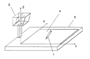
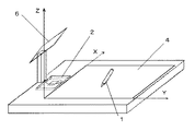
図1は、本発明の第1の実施形態における光学式座標入力装置の構成を示す平面図である。また、図2は、本発明の第1の実施形態における光学式座標入力装置の構成を示す斜視図である。
【0021】
光学式座標入力装置は、座標指示部材1と、光信号検出手段2と、中央制御手段3と、情報表示部4と、光学式座標入力装置の筐体5とを有する。
【0022】
図1および図2に示されているように、光信号検出手段2は、LCDまたはCRTのディスプレイ等の情報表示部4に、操作者の保持する座標指示部材1と対向する所定の空間位置に設置される。
【0023】
座標指示部材1は、発光信号を出力する。また、座標指示部材1は、座標入力用スタイラスペンであってもよい。
【0024】
光信号検出手段2は、角度検出部と演算部とを有し、座標指示部材1からの発光信号およびその入射角を検出する。
【0025】
中央制御手段3は、演算結果等を記憶する記憶手段を有し、各種演算と各ユニットを制御する。
【0026】
図3は、本発明の第1の実施形態における座標指示部材1を示す図である。座標指示部材1は、透明樹脂10と、発光素子11と、駆動回路12と、制御手段13と、感圧スイッチ14と、拡散光学系15と、を有する。
【0027】
透明樹脂10は、座標指示部材1の先端に設けられており、例えば赤外光に透明である。
【0028】
発光素子11は、座標指示部材1の所定の位置に搭載されており、赤外LEDなどの発光素子である。
【0029】
駆動回路12は、制御手段13の指示を受けて、発光素子11を駆動させる。
【0030】
制御手段13は、座標指示部材1における各部位を制御する。
【0031】
感圧スイッチ14は、ユーザが座標指示部材1で情報表示部4上を押圧して所定の座標を指示すると、その座標指示を検出する。
【0032】
拡散光学系15は、図3に示されているように、座標指示部材1の先端部位に設けられており、透明な部材の先端周辺に発光素子11からの照射ビーム光を拡散する。
【0033】
例えば赤外光に透明な透明樹脂10を円錐状に成型後、頂点部分を円錐状に堀り、適当に加工面を荒らした後、例えば赤外光を反射するアルミ等の金属薄膜などを塗布後、指示部保護用のゴム状の物質や樹脂などで先端部分16を指示しやすい形に、拡散光学系15が埋め込まれる。そして発光素子11からの出射ビームを透明樹脂10の底面から上記加工面上に照射するように発光素子11を座標指示部材1内に配置する。
【0034】
図4は、本発明の第1の実施形態における光信号検出手段2を示す図である。
光信号検出手段2は、演算部22と、角度検出部26とを有する。また、角度検出部26は、レンズ20と、受光素子21とを有し、演算部22は、演算回路23と、検波手段24と、同期手段25と、増幅器と、加算器と、BPF(Band Pass Filter)とを有する。受光素子21は、レンズ20の焦点面に設置した入射スポット位置を検出する。角度検出部26は、例えばPSD(Position Sensing Device)やCCD(Charge Coupled Device)等の半導体素子からなり、座標指示部材1の発光部からの拡散光の信号成分とその入射方向を検出する。
【0035】
以下、図3および図4を用いて、本実施形態における光学式座標入力装置による位置検出動作について説明する。
【0036】
座標指示部材1が情報表示部4表面の所望の座標を指示すると、座標指示部材1の先端部分に設けられた感圧スイッチ14は、指示動作を検出して、制御手段13に座標指示を通知する。制御手段13は、駆動回路12を介して発光素子11を駆動させる。座標指示部材1最先端部の拡散光学系15は、発光素子11から光信号を受けて、拡散光として送信する。
【0037】
本実施形態では、さらに発光素子11を所定のデューティ比を有するパルス駆動とすることにより、発光素子11の単位時間あたりの平均出力パワーを抑えて、操作者がペン先(座標指示部材1の先端部)を注視しても眼に安全であるようにしている。
【0038】
検波手段24がベースバンド信号を抽出後、同期手段25は同期を取る。演算手段23は、この同期信号を基にスポット位置情報を検出して、その入射方向を算出する。
【0039】
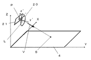
図5は、本発明の第1の実施形態における光学式座標入力装置を示す図である。以下、図5を用いて、光学式座標入力装置による指示点の算出方法について説明する。ただし、ここでは情報表示部4画面の直交する2辺をX軸及びY軸(以後表示座標系という)とする。
【0040】
図4に示されるように、光信号検出手段2は、レンズ20とその焦点距離位置を検出する受光素子21(PSDまたはCCDなどの入射スポット位置情報を出力する受光素子、本実施形態はPSDを用いている)とを有する。
【0041】
光信号検出手段2は、光信号検出手段2の集光スポットの情報表示部4における受光面上の位置情報(例えば、本実施形態のPSDの場合、受光面の各辺上に設けられた各電極からの光電流値の線形演算値)を光信号の受信信号と同期して検出する。なお、受光面重心位置がレンズ光軸上に一致する構成の場合、演算結果がそのままスポット位置情報をあらわす。
【0042】
レンズ20の焦点距離及び受光面上に想定するローカルな座標系を、例えば、レンズ20の光軸をy’軸、矩形受光面の各辺に平行にx’及びz’軸、光学中心を原点とすると、座標系上でのスポット位置P(x’p,z’p)と入射方位(方向ベクトル)V’=(V’x,V’y,V’z)成分とは直線tV’(tは任意の数)と平面y’=fとの交点の関係から次式の関係が成立し、これより演算手段23にて入射方向ベクトルを算出する。
【0043】
x’p/V’x=f/V’y=z’p/V’z
【0044】
次に、中央制御手段3は、このローカル座標系と表示座標系との対応関係に注意して、表示座標系での入射方向ベクトルVに変換する。ここで、指示位置S(=拡散光学系15の位置)は、情報表示部4の表示平面上における位置座標であるとみなせる。従って、求める指示位置Sは、光信号検出手段2の光学中心位置をLとすると、光信号検出手段2の光学中心位置L(表示座標系での座標値、製造時に既知)を通る直線OL+kV(kは任意の数、Oは原点、Vはベクトル)と表示平面Z=0との交点として求まる。この関係から中央制御手段3は、所定の一次元の線形の連立方程式を解くことにより、その解として、指示位置Sの位置座標値を算出する。
【0045】
以上説明したように、本実施形態によれば、座標指示部材1は、所定の信号を重畳して拡散光を発光する。光信号検出手段2は、その拡散光の光信号成分および入射角度成分を同期して検出する。中央制御手段3は、光信号検出手段2により検出された拡散光の光信号成分および入射角度成分から、座標指示部材1による情報表示部4上の指示位置を算出する。従って、本実施形態によれば、簡単な構成で安定した位置検出精度を有する安全な光学式座標入力装置を提供することが可能となる。
【0046】
また、本実施形態によれば、座標指示部材1は、その先端が情報表示部4上に接触したことを検出すると、発光素子11を駆動させる。従って、不要な電力の消費を防ぐことが可能となる。
【0047】
(第2の実施形態)
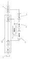
図6は、本発明の第2の実施形態における光学式座標入力装置の構成を示す平面図である。また、図7は、本発明の第2の実施形態における光学式座標入力装置の構成を示す斜視図である。
【0048】
光学式座標入力装置は、座標指示部材1と、光信号検出手段2と、中央制御手段3と、情報表示部4と、光路変換手段6と、を有する。
【0049】
図6および図7に示されているように、光信号検出手段2は、LCDまたはCRTのディスプレイ等の情報表示部4に操作者の保持する座標指示部材1と対向する所定の位置に設置される。また、光信号検出手段2の光軸上、座標指示部材1との光路上に座標指示部材1からの光信号を光信号検出手段2に入射させるよう、所定の角度に設置したミラーによる光路変換手段6を有する。光学式座標入力装置における検出側ユニットは、光路変換手段6を介して入射する座標指示部材1からの発光信号およびその入射角を検出する光信号検出手段2(角度検出部と演算部とを有する)と、各種演算と各ユニットを制御する中央制御処理手段3(演算結果等を記憶する記憶手段を含む)とを有する。
【0050】
本実施形態における座標指示部材1は、以下特記しない限り、図3に示される第1の実施形態における座標指示部材1と同様であるとする。また、本実施形態における光信号検出手段2は、以下特記しない限り、図4に示される第1の実施形態における光信号検出手段2と同様であるとする。以下、図3および図4を用いて、座標指示部材1および光信号検出手段2の構成・動作を説明する。また、中央制御手段3および情報表示部4に関しても、以下特記しない限り、第1の実施形態と同様であるとする。
【0051】
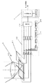
図8は、本発明の第2の実施形態における光学式座標入力装置の構成を示す断面図である。図8に示されるように、光路変換手段6は、昇降機構部71と、角度保持機構部72と、ミラー搭載部74とを有する。
【0052】
ミラー搭載部74は、座標指示部材1の拡散光の光路を調節して、光信号検出手段2に照射するミラーを光信号検出手段2上に搭載している。ミラー搭載部74は、角度保持機構部72を介して昇降機後部71に連設されている。
【0053】
昇降機構部71は、光路変換手段6使用時には、所望の高さにミラー搭載部74を保持可能なように設けられており、光信号検出手段2とミラー搭載部74との間の距離(高さ)を調節可能なように設けられている。
【0054】
角度保持機構部72は、光路変換手段6使用時には、所望の角度にミラー搭載部74を保持可能なように設けられており、光信号検出手段2に対するミラー搭載部74の角度を調節可能なように設けられている。
【0055】
光路変換手段6が使用されないときには、例えば、ミラー搭載部74は、光信号検出手段2に蓋をするような状態に保持可能となるように設けられる。
【0056】
ミラー搭載部74を押すことにより、機械的に使用可能な状態に保持される。
このとき、光信号検出手段2の所定部分に感圧スイッチ73を設け、光路変換手段6が稼動した際に感圧スイッチ73がONになり、検出側ユニットの電源を入れるようにする。従って、操作者にわかりやすく、確実な電源の投入が可能になる(当然、ミラー搭載部74が閉じられた状態では感圧スイッチ73はOFFになる)。
【0057】
光路変換手段6は、座標指示部材1からの赤外光のみを反射するように、表面に誘電体多層膜等のフィルタ部材を設けておく。従って、蛍光灯などからの不要な外光を低減して、誤動作を防ぐようにしている。
【0058】
以下、図3および図4を用いて、本実施形態における光学式座標入力装置による位置検出動作について説明する。
【0059】
座標指示部材1が情報表示部4表面の所望の座標を指示すると、座標指示部材1の先端部分に設けられた感圧スイッチ14は、指示動作を検出して、制御手段13に座標指示を通知する。制御手段13は、駆動回路12を介して発光素子11を駆動させる。座標指示部材1最先端部の拡散光学系15は、発光素子11から光信号を受けて、拡散光として送信する。
【0060】
本実施形態では、さらに発光素子11を所定のデューティ比を有するパルス駆動とすることにより、発光素子11の単位時間あたりの平均出力パワーを抑えて、操作者がペン先(座標指示部材1の先端部)を注視しても眼に安全であるようにしている。
【0061】
座標指示部材1から発信された光信号は、光路変換手段6により一部が光信号検出手段2に照射される。すなわち、光路変換手段6は、入射する光信号のうち所定の波長の光信号のみを光信号検出手段2に対して照射する。従って、座標指示部材1の発光光以外の光信号が、光信号検出手段2に入射することを抑制し、誤作動のない光学式座標入力装置を提供することが可能となる。
【0062】
検波手段24がベースバンド信号を抽出後、同期手段25は同期を取る。演算手段23は、この同期信号を基にスポット位置情報を検出して、その入射方向を算出する。このとき、光路変換手段6による固定の角度変化量(偏向角)をオフセット量として加算する。
【0063】
図4に示されるように、光信号検出手段2は、レンズ20とその焦点距離位置を検出する受光素子21(PSDまたはCCDなどの入射スポット位置情報を出力する受光素子、本実施形態はPSDを用いている)とを有する角度検出部26と、角度情報を演算する演算部22とを有する。
【0064】
光信号検出手段2は、角度検出部26の集光スポットの受光面上の位置情報(例えば、本実施形態のPSDの場合、受光面の各辺上に設けられた各電極からの光電流値の線形演算値)を光信号の受信信号と同期して検出する。なお、受光面重心位置がレンズ光軸上に一致する構成の場合、演算結果がそのままスポット位置情報をあらわす。
【0065】
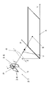
図9は、本発明の第2の実施形態における光学式座標入力装置を示す図である。以下、図9を用いて、本実施形態における光学式座標入力装置による指示点の算出方法について説明する。ただし、本実施形態では情報表示部4画面上の直交する2辺をX軸及びY軸(以後表示座標系という)とする。
【0066】
例えば、本実施形態のようにミラーの設置角度が角度検出部26の光軸に対し45度に設置している場合、図9に示されるように、光路変換手段6による角度オフセット量を演算部による入射角度情報に加算することは、90度変換された光軸の延長線上の、ミラー部―角度検出部の光学中心間距離だけ離れた位置に、仮想の角度検出部(=虚像37)を設置したことと等価である。ただし、X軸方向は鏡により左右逆になる。
【0067】
虚像37上の光学系35の焦点距離及び受光面36上に想定するローカルな座標系を、例えば、レンズ20の光軸をy’軸、矩形受光面の各辺に平行にx’及びz’軸、光学中心を原点とすると、座標系上でのスポット位置P(x’p,z’p)と入射方位(方向ベクトル)V’=(V’x,V’y,V’z)成分とは直線tV’(tは任意の数)と平面y’=fとの交点の関係から次式の関係が成立し、これより演算手段23にて入射方向ベクトルを算出する。
【0068】
x’p/V’x=f/V’y=z’p/V’z
【0069】
次に、中央制御手段3は、このローカル座標系と表示座標系との対応関係に注意して、表示座標系での入射方向ベクトルVに変換する。ここで、指示位置S(=拡散光学系15の位置)は、情報表示部4の表示平面上における位置座標であるとみなせる。従って、求める指示位置Sは、仮想角度検出部(虚像37)の光学中心位置をLとすると、光信号検出手段2の光学中心位置L(表示座標系での座標値、製造時に既知)を通る直線OL+kV(kは任意の数、Oは原点、Vはベクトル)と表示平面Z=0との交点として求まる。この関係から中央制御手段3は、所定の一次元の線形の連立方程式を解くことにより、その解として、指示位置Sの位置座標値を算出する。
【0070】
以上説明したように、本実施形態によれば、光路変換手段6は、座標指示部材1からの拡散光の光路の方向を調節して、光信号検出手段2にその拡散光を入射させる。従って、計測精度を向上させるために光信号検出手段2を情報表示部4から所定の高さの位置に設置する必要がなくなり、光学式座標入力装置の小型化を実現することが可能となる。
【0071】
また、本実施形態によれば、光路変換手段6には、座標指示部材1からの赤外光のみを反射するように、表面に誘電体多層膜等のフィルタ部材が設けられている。従って、蛍光灯などからの不要な外光を低減して、誤動作を防ぐことが可能となる。
【0072】
(第3の実施形態)
本発明の第3の実施形態では、座標指示部材1から光信号検出手段2に送信する光信号に一義的に決まる識別情報を付加することにより、複数の赤外線装置が動作する環境であっても、誤作動のない光学式座標入力装置を実現する。以下、特記しない限り、本発明の第3の実施形態における構成および動作は、第1の実施形態における構成および動作と同様であるとする。
【0073】
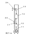
図10は、本発明の第3の実施形態における座標指示部材1を示す図である。
本実施形態において、座標指示部材1は、発光素子11と、駆動回路12と、制御手段13と、入力手段30と、入力情報検出手段31と、記憶手段33と、切り返しスイッチ34と、を有する。
【0074】
発光素子11、駆動回路12、および制御手段13は、第1の実施形態と同様であるとする。
【0075】
入力手段30は、例えば、所定のボタン/スイッチなどであって、情報を入力する。入力情報検出手段31は、入力手段30による情報入力を検出する。
【0076】
記憶手段33は、座標指示部材1から送信する光信号を一義的に識別するための1つ以上の識別情報を記憶する。
【0077】
切り返しスイッチ34は、記憶手段33に記憶されている1つ以上の識別情報のうち所定の識別信号を選択する情報入力部位である。
【0078】
本実施形態では、座標指示部材1は、記憶手段33に予め記憶させている識別情報のうち所定の1つを切り返しスイッチ34を用いて選択する。
【0079】
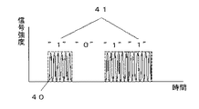
図11は、本発明の第3の実施形態における座標指示部材1が光信号検出手段2に送信する光信号の変調を示す図である。図11に示されるように、切り返しスイッチ34により選択情報が入力されると、発光素子11(本実施形態では、例えば赤外LEDなど)の光出力を制御する制御手段13は、搬送信号に変調信号40を重畳して発光素子11からの拡散光を直接変調41する。なお、座標指示部材1は、光信号をASK(Amplitude Shift Keying)方式により伝送する。
【0080】
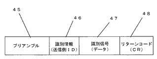
図12は、本発明の第3の実施形態における座標指示部材1が光信号検出手段2に送信する光信号のフレーム構成を示す図である。図12に示されているように、座標指示部材1は、例えば受信側(光信号検出手段2側)で同期を取るためのプリアンブル45につづき、選択された識別信号に基づく識別情報(送信側ID)46を送信する。例えば、座標指示部材1を用いてマウスのエミュレートを行って、情報表示部4の表示画面上の画像情報を制御する場合、表示画面上のGUI(Graphical User Interface)操作等に必須なクリック動作等を指示する必要がある。そこで、図10に示すようなマウス上のクリックボタンに相当する入力手段30を座標指示部材1上に設け、座標指示部材1は、入力手段30が押されたことを検知して、対応する情報信号47を識別情報46の後に付加している。そして、座標指示部材1は、最後にリターンコード48を付加して通信を行う。
【0081】
図13は、本発明の第3の実施形態における光信号検出手段2を示す図である。受信側(光信号検出手段2側)では、図13に示すように、例えば受光素子21からの信号を用い、検波手段24によりベースバンド信号を抽出後、同期手段25により同期を取り、この同期信号を元に判定器50および復調手段51により所望のデジタル信号に復調する。次に、中央制御手段3は、座標指示部材1の識別信号46と対応する操作指示信号を識別して、次段の情報機器に所定の信号を伝送する。また、上記の同期信号を元にサンプリングして入射角度情報も検出して、光信号検出手段2の位置情報をもとに座標指示部材1による指示座標を算出する。
【0082】
以上説明したように、本実施形態では、座標指示部材1は、光信号検出手段2に送信する光信号に識別信号46を付加することにより、他に赤外線装置が存在しているような環境でも、光信号検出手段2は、一義的に決まる識別信号46により誤動作することなく光信号を検出することが可能となり、誤動作を防止することが可能となる。また、前記識別信号と座標位置とを対応付けることにより、複数の指示部材(ただし、識別信号はお互い異なる)による同時操作を可能にする。
【0083】
また、本実施形態によれば、座標指示部材1は、記憶手段33に予め記憶させている識別情報のうち所定の1つを切り返しスイッチ34を用いて選択する。従って、操作者の意図した指示を送信することが可能で、光学式座標入力装置を搭載した情報処理装置の操作性を向上させることが可能である。
【0084】
(第4の実施形態)
本発明の第4の実施形態では、光信号検出手段2が座標指示部材1からの拡散光の入射角度を算出する際に、拡散光の受光強度が所定のレベル以下の場合、光信号検出手段2は、座標指示部材1の指示座標位置を所定の規定値の検出位置情報、もしくは直前に検出した検出位置情報にホールドする。従って、本実施形態では、不要な誤動作や誤検出を防止することが可能で、操作者に違和感の少ない操作性を提供することが可能となる。なお、上記した以外の構成および動作については、第1の実施形態と同様であるとする。
【0085】
(第5の実施形態)
本発明の第5の実施形態では、光信号検出手段2は、座標指示部材1の拡散光と異なる波長の光を受光した際において、可視光LEDの発光、または小型の液晶表示素子によるバー表示等により、受光素子21での検出光(座標指示部材1の拡散光)の受光レベルを可視化して表示する。
【0086】
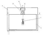
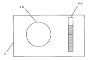
図14は、本発明の第5の実施形態における光信号検出手段2を示す図である。以下、図14を用いて、本実施形態における構成および動作について説明する。
【0087】
図14に示されているように、例えば、光信号検出手段2は、ある規定受光強度に達した際に表示用LCDのバーグラフ60を受光レベルに比例するよう変化させて受光強度を表示する。従って、本実施形態によれば、座標指示部材1からの発光光が正常に検出されていることが確認可能で、誤動作の防止や故障等の早期発見などが可能になる。
【0088】
また、図15は、本発明の第5の実施形態の変形例における光信号検出手段2を示す図である。図15に示されているように、光信号検出手段2は、表示用に可視光LEDを光信号検出手段2に対向する面上に設け、受光部での検出光の受光レベルが一定以上の場合に所定のLED62を発光表示したり、一定時間の受光レベルが一定以下の場合に、Lowレベルを警告するLED61を発光表示したりすることにより、座標指示部材1からの発光光が正常に検出されているかどうかの確認が可能で、誤動作の防止や故障等の早期発見などが可能になる。
【0089】
なお、バーグラフ60、LED61、62は、光信号検出手段2に設けるとしたが、第2の実施形態の構成に適用する場合には、光路変換手段6において、ミラー搭載部74に対向する面上に設けるとしてよい。
【0090】
なお、上記の実施形態は本発明の好適な実施の一例であり、本発明の実施形態は、これに限定されるものではなく、本発明の要旨を逸脱しない範囲において種々変形して実施することが可能となる。
【0091】
例えば、光信号検出手段2に座標指示部材1からの拡散光の光源波長以外に光の入射を防止するための光学フィルタを設けることにより、外乱光などの光ノイズを低減し、S/N比を向上させることが可能となる。
【0092】
また、座標指示部材1の判別に複数の発振器による搬送波の周波数を切り替え、受信側(光信号検出手段2)にて対応するバンドパスフィルタにより受信信号を検出することによる識別も可能である。
【0093】
さらに、ラインセンサ等の1次元のセンサを直交するように配置して、それぞれのセンサに光学系として円筒レンズを所定の位置に配置する構成でも光信号検出手段2を実現できる。
【0094】
なお、以上説明した光学式座標入力装置を二次元情報を計測する計測装置等に応用するとしてもよい。
【0095】
また、上記の処理は、光学式座標入力装置が有するコンピュータプログラムにより実行されるが、上記のプログラムは、光記録媒体、磁気記録媒体、光磁気記録媒体、または半導体等の記録媒体に記録され、上記の記録媒体からロードされるようにしてもよいし、所定のネットワークを介して接続されている外部機器からロードされるようにしてもよい。
【0096】
【発明の効果】
以上説明したように、本発明によれば、座標指示部材は、所定の信号を重畳して拡散光を発光する。光信号検出手段は、その拡散光の光信号成分および入射角度成分を同期して検出する。演算部は光信号検出手段により検出された拡散光の光信号成分および入射角度成分から、座標指示部材による情報表示部上の指示位置を算出する。従って、本発明によれば、簡単な構成で安定した位置検出精度を有する安全な光学式座標入力装置を提供することが可能となる。
【0097】
また、本発明によれば、座標指示部材は、その先端が情報表示部上に接触したことを検出すると、発光手段を駆動させる。従って、不要な電力の消費を防ぐことが可能となる。
【0098】
また、本発明によれば、光路変換手段は、座標指示部材からの拡散光の光路の方向を調節して、光信号検出手段にその拡散光を入射させる。従って、計測精度を向上させるために光信号検出手段を情報表示部から所定の高さの位置に設置する必要がなくなり、光学式座標入力装置の小型化を実現することが可能となる。
【0099】
また、本発明によれば、光路変換手段は、所定の波長の光の光路のみを方向変換する。従って、蛍光灯などからの不要な外光を低減して、誤動作を防ぐことが可能となる。
【0100】
また、本発明によれば、識別情報格納手段により記憶されている識別情報のうち所定の1つを情報選択手段を用いて選択する。従って、操作者の意図した指示を送信することが可能で、光学式座標入力装置を搭載した情報処理装置の操作性を向上させることが可能である。
【0101】
表示部および受光レベル表示部は、光信号検出手段による受光レベルを表示する。従って、本発明によれば、座標指示部材からの発光光が正常に検出されていることが確認可能で、誤動作の防止や故障等の早期発見などが可能になる。
【図面の簡単な説明】
【図1】本発明の第1の実施形態における光学式座標入力装置の構成を示す平面図である。
【図2】本発明の第1の実施形態における光学式座標入力装置の構成を示す斜視図である。
【図3】本発明の第1の実施形態における座標指示部材を示す図である。
【図4】本発明の第1の実施形態における光信号検出手段を示す図である。
【図5】本発明の第1の実施形態における光学式座標入力装置を示す図である。
【図6】本発明の第2の実施形態における光学式座標入力装置の構成を示す平面図である。
【図7】本発明の第2の実施形態における光学式座標入力装置の構成を示す斜視図である。
【図8】本発明の第2の実施形態における光学式座標入力装置の構成を示す断面図である。
【図9】本発明の第2の実施形態における光学式座標入力装置を示す図である。
【図10】本発明の第3の実施形態における座標指示部材を示す図である。
【図11】本発明の第3の実施形態における座標指示部材が光信号検出手段に送信する光信号の変調を示す図である。
【図12】本発明の第3の実施形態における座標指示部材が光信号検出手段に送信する光信号のフレーム構成を示す図である。
【図13】本発明の第3の実施形態における光信号検出手段を示す図である。
【図14】本発明の第5の実施形態における光信号検出手段を示す図である。
【図15】本発明の第5の実施形態の変形例における光信号検出手段を示す図である。
【図16】(a)は、従来技術における遠隔指示入力装置の構成を示す図であり、(b)は、(a)の遠隔指示棒の構成を示す図であり、(c)および(d)は、それぞれ遠隔指示棒中に配置されるスリットの正面図である。
【符号の説明】
1 座標指示部材
2 光信号検出手段
3 中央制御手段
4 情報表示部
5 筐体
6 光路変換手段
10 透明樹脂
11 発光素子
12 駆動回路
13 制御手段
14、73 感圧スイッチ
15 拡散光学系
16 先端部分
20 レンズ
21 受光素子
22 演算部
23 演算回路
24 検波回路
25 同期手段
26 角度検出部
30 入力手段
31 入力情報検出手段
33 記憶手段
34 切り返しスイッチ
40 変調信号
41 変調
45 プリアンブル
46 識別情報
47 情報信号
48 リターンコード
50 判定器
51 復号手段
60 バーグラフ
61、62 LED
71 昇降機構部
72 角度保持機構部
74 ミラー搭載部
L 光学中心位置
P スポット位置
S 指示位置
V、V’ ベクトル[0001]
BACKGROUND OF THE INVENTION
The present inventionOptical coordinate input device and optical coordinate input methodIn particular, it is possible to obtain input information on paper, or input to a two-dimensional coordinate area for inputting movement data and stroke data of a cursor on the screen of a personal computer, an amusement input device, a portable terminal, etc. NaOptical coordinate input device and optical coordinate input methodAbout.
[0002]
[Prior art]
Conventionally, there has been a remote instruction input device disclosed in JP-A-5-119918 (hereinafter referred to as Patent Document 1) as a coordinate input device that detects diffused light from an indicated region and detects an indicated coordinate position. . In
[0003]
[Patent Document 1]
JP-A-5-119918
[0004]
[Problems to be solved by the invention]
16A is a diagram showing a configuration of a remote instruction input device in the prior art, FIG. 16B is a diagram showing a configuration of a remote indicator bar of FIG. 16A, and FIGS. These are the front views of the slit each arrange | positioned in a remote indicator stick | rod.
[0005]
The remote instruction input device shown in FIG. 16 is intended for detection of position information on a projection screen on a screen such as a projector, and has a diffuse reflection characteristic from an information display surface such as an information display device such as an LCD screen. The application as it is to an inferior display device is difficult, and there is a limit to the display device that can be applied. In addition, when a conventional remote instruction input device is used for an input device such as a PC, there is a problem in terms of safety for eyes because an operator pays attention to a pointed portion.
[0006]
The present invention has been made in view of the above problems, and has a simple configuration and a stable position detection accuracy.Optical coordinate input device and optical coordinate input methodThe purpose is to provide.
[0007]
[Means for Solving the Problems]
In order to achieve this object, the invention described in
[0008]
The invention according to claim 22. The apparatus according to
[0009]
According to a third aspect of the present invention, in the optical coordinate input device according to the first or second aspect, the coordinate indicating member selects the information indicated by the signal superimposed on the light emitted by the light emitting means. The drive control means superimposes a signal indicating the information selected by the information selection means on the emitted light, andthe onlyThe optical signal detection means converts the signal of the emitted light based on the information selected by the information selection means.
[0010]
According to a fourth aspect of the present invention, in the apparatus according to any one of the second to third aspects, the coordinate indicating member stores one or more pieces of identification information for identifying each optical signal. Identification information storage means, wherein the information selection means selects predetermined identification information from one or more pieces of identification information stored by the identification information storage means, and the drive control means A modulation signal based on the identification information selected by the selection unit is superimposed on the signal of the emitted light, andthe onlyThe optical signal detection means demodulates the modulation signal superimposed on the emitted light into the identification information,the onlyThe calculation unit provided in the optical signal detection means isthe onlyIn association with the identification information demodulated by the optical signal detection means, the position on the plane irradiated with diffused light by the coordinate indicating member is calculated.
[0011]
According to the invention of
[0012]
According to the invention as set forth in
[0013]
According to the invention of
[0014]
According to an eighth aspect of the present invention, in the apparatus according to any one of the second to seventh aspects, the light emitting means of the coordinate indicating member and thethe onlyIt is provided between the optical paths with the optical signal detection means, and has an optical path conversion means for converting the direction of the optical path.
[0015]
According to the invention of claim 9,9. The apparatus according to claim 8, wherein the optical path changing means is provided with a movable mirror.
[0016]
According to the invention of
[0017]
According to the invention of claim 11, in the apparatus of any one of claims 8 to 10, the optical path changing means isthe onlyIt has a light reception level display part which displays the information which shows the light reception level by an optical signal detection means.
[0018]
The invention according to
[0020]
DETAILED DESCRIPTION OF THE INVENTION
(First embodiment)
FIG. 1 is a plan view showing the configuration of the optical coordinate input device according to the first embodiment of the present invention. FIG. 2 is a perspective view showing the configuration of the optical coordinate input device according to the first embodiment of the present invention.
[0021]
The optical coordinate input device includes a coordinate indicating
[0022]
As shown in FIG. 1 and FIG. 2, the optical signal detection means 2 is placed at a predetermined spatial position facing the coordinate indicating
[0023]
The coordinate indicating
[0024]
The optical
[0025]
The central control means 3 has storage means for storing calculation results and the like, and controls various calculations and each unit.
[0026]
FIG. 3 is a view showing the coordinate indicating
[0027]
The
[0028]
The light emitting element 11 is mounted at a predetermined position of the coordinate indicating
[0029]
The
[0030]
The control means 13 controls each part in the coordinate indicating
[0031]
When the user presses the
[0032]
As shown in FIG. 3, the diffusion optical system 15 is provided at the distal end portion of the coordinate indicating
[0033]
For example, after
[0034]
FIG. 4 is a diagram showing the optical signal detection means 2 in the first embodiment of the present invention.
The optical
[0035]
Hereinafter, the position detection operation by the optical coordinate input device according to the present embodiment will be described with reference to FIGS. 3 and 4.
[0036]
When the coordinate indicating
[0037]
In the present embodiment, the light emitting element 11 is further pulse-driven having a predetermined duty ratio, so that the average output power per unit time of the light emitting element 11 can be suppressed and the operator can use the pen tip (the tip of the coordinate indicating member 1). Part) is safe for eyes.
[0038]
After the
[0039]
FIG. 5 is a diagram showing an optical coordinate input device according to the first embodiment of the present invention. Hereinafter, a method for calculating the designated point by the optical coordinate input device will be described with reference to FIG. However, here, two orthogonal sides of the
[0040]
As shown in FIG. 4, the optical signal detection means 2 includes a
[0041]
The optical signal detection means 2 includes position information on the light receiving surface in the
[0042]
The focal length of the
[0043]
x'p / V'x = f / V'y = z'p / V'z
[0044]
Next, the central control means 3 pays attention to the correspondence between the local coordinate system and the display coordinate system, and converts it into an incident direction vector V in the display coordinate system. Here, the designated position S (= the position of the diffusion optical system 15) can be regarded as the position coordinates on the display plane of the
[0045]
As described above, according to the present embodiment, the coordinate indicating
[0046]
Further, according to the present embodiment, the coordinate indicating
[0047]
(Second Embodiment)
FIG. 6 is a plan view showing the configuration of the optical coordinate input device according to the second embodiment of the present invention. FIG. 7 is a perspective view showing the configuration of the optical coordinate input device according to the second embodiment of the present invention.
[0048]
The optical coordinate input device includes a coordinate indicating
[0049]
As shown in FIGS. 6 and 7, the optical
[0050]
The coordinate indicating
[0051]
FIG. 8 is a cross-sectional view showing a configuration of an optical coordinate input device according to the second embodiment of the present invention. As shown in FIG. 8, the optical
[0052]
The
[0053]
The elevating mechanism 71 is provided so as to be able to hold the
[0054]
The angle
[0055]
When the optical
[0056]
By pushing the
At this time, a pressure
[0057]
The optical path conversion means 6 is provided with a filter member such as a dielectric multilayer film on the surface so as to reflect only infrared light from the coordinate indicating
[0058]
Hereinafter, the position detection operation by the optical coordinate input device according to the present embodiment will be described with reference to FIGS. 3 and 4.
[0059]
When the coordinate indicating
[0060]
In the present embodiment, the light emitting element 11 is further pulse-driven having a predetermined duty ratio, so that the average output power per unit time of the light emitting element 11 can be suppressed and the operator can use the pen tip (the tip of the coordinate indicating member 1). Part) is safe for eyes.
[0061]
A part of the optical signal transmitted from the coordinate indicating
[0062]
After the
[0063]
As shown in FIG. 4, the optical signal detection means 2 includes a
[0064]
The optical signal detection means 2 is the position information on the light receiving surface of the condensing spot of the angle detection unit 26 (for example, in the case of the PSD of this embodiment, the photocurrent value from each electrode provided on each side of the light receiving surface. (Linear calculation value) is detected in synchronization with the received signal of the optical signal. Note that in the case where the center of gravity of the light receiving surface coincides with the lens optical axis, the calculation result directly represents spot position information.
[0065]
FIG. 9 is a diagram showing an optical coordinate input device according to the second embodiment of the present invention. Hereinafter, with reference to FIG. 9, a method for calculating the indicated point by the optical coordinate input device according to the present embodiment will be described. However, in the present embodiment, two orthogonal sides on the
[0066]
For example, when the installation angle of the mirror is 45 degrees with respect to the optical axis of the angle detection unit 26 as in the present embodiment, as shown in FIG. Is added to the incident angle information by the virtual angle detection unit (= virtual image 37) at a position on the extension line of the optical axis converted by 90 ° by a distance between the optical center of the mirror unit and the angle detection unit. It is equivalent to installing it. However, the X axis direction is reversed left and right by the mirror.
[0067]
The focal length of the optical system 35 on the
[0068]
x'p / V'x = f / V'y = z'p / V'z
[0069]
Next, the central control means 3 pays attention to the correspondence between the local coordinate system and the display coordinate system, and converts it into an incident direction vector V in the display coordinate system. Here, the designated position S (= the position of the diffusion optical system 15) can be regarded as the position coordinates on the display plane of the
[0070]
As described above, according to the present embodiment, the optical
[0071]
Further, according to the present embodiment, the optical
[0072]
(Third embodiment)
In the third embodiment of the present invention, even in an environment where a plurality of infrared devices are operated by adding identification information uniquely determined to the optical signal transmitted from the coordinate indicating
[0073]
FIG. 10 is a diagram showing the coordinate indicating
In the present embodiment, the coordinate indicating
[0074]
The light emitting element 11, the
[0075]
The input means 30 is, for example, a predetermined button / switch or the like, and inputs information. The input information detection unit 31 detects information input by the
[0076]
The storage means 33 stores one or more pieces of identification information for uniquely identifying the optical signal transmitted from the coordinate indicating
[0077]
The
[0078]
In the present embodiment, the coordinate designating
[0079]
FIG. 11 is a diagram illustrating modulation of an optical signal transmitted from the coordinate designating
[0080]
FIG. 12 is a diagram showing a frame configuration of an optical signal transmitted from the coordinate designating
[0081]
FIG. 13 is a diagram showing the optical signal detection means 2 in the third embodiment of the present invention. On the receiving side (optical signal detecting means 2 side), as shown in FIG. 13, for example, a signal from the
[0082]
As described above, in the present embodiment, the coordinate indicating
[0083]
Further, according to the present embodiment, the coordinate designating
[0084]
(Fourth embodiment)
In the fourth embodiment of the present invention, when the optical signal detection means 2 calculates the incident angle of the diffused light from the coordinate indicating
[0085]
(Fifth embodiment)
In the fifth embodiment of the present invention, when the optical
[0086]
FIG. 14 is a diagram showing the optical signal detection means 2 in the fifth embodiment of the present invention. Hereinafter, the configuration and operation of the present embodiment will be described with reference to FIG.
[0087]
As shown in FIG. 14, for example, the optical signal detection means 2 displays the light reception intensity by changing the
[0088]
FIG. 15 is a diagram showing the optical signal detection means 2 in a modification of the fifth embodiment of the present invention. As shown in FIG. 15, the optical signal detection means 2 is provided with a visible light LED on the surface facing the optical signal detection means 2 for display, and the light receiving level of the detection light at the light receiving portion is a certain level or more. In this case, the light emitted from the coordinate indicating
[0089]
Although the
[0090]
The above-described embodiment is an example of a preferred embodiment of the present invention. The embodiment of the present invention is not limited to this, and various modifications may be made without departing from the scope of the present invention. Is possible.
[0091]
For example, by providing the optical signal detection means 2 with an optical filter for preventing the incidence of light other than the light source wavelength of the diffused light from the coordinate indicating
[0092]
Further, it is possible to identify the coordinate indicating
[0093]
Furthermore, the optical signal detection means 2 can also be realized by a configuration in which one-dimensional sensors such as line sensors are arranged orthogonally and a cylindrical lens is arranged at a predetermined position as an optical system for each sensor.
[0094]
The optical coordinate input device described above may be applied to a measuring device that measures two-dimensional information.
[0095]
The above processing is executed by a computer program included in the optical coordinate input device. The above program is recorded on a recording medium such as an optical recording medium, a magnetic recording medium, a magneto-optical recording medium, or a semiconductor, You may make it load from said recording medium, and you may make it load from the external apparatus connected via the predetermined | prescribed network.
[0096]
【The invention's effect】
As described above, according to the present invention, the coordinate indicating member emits diffused light by superimposing a predetermined signal. The optical signal detection means detects the optical signal component and the incident angle component of the diffused light in synchronization.The calculation part isThe indicated position on the information display unit by the coordinate indicating member is calculated from the optical signal component and the incident angle component of the diffused light detected by the optical signal detecting means. Therefore, according to the present invention, a safe optical coordinate input having a stable position detection accuracy with a simple configuration.apparatusCan be provided.
[0097]
According to the invention, the coordinate indicating member drives the light emitting means when detecting that the tip of the coordinate indicating member is in contact with the information display unit. Therefore, unnecessary power consumption can be prevented.
[0098]
Moreover, according to the present invention, the optical path conversionmeansDetects the optical signal by adjusting the direction of the optical path of the diffused light from the coordinate indicating membermeansThe diffused light is incident on. Therefore, optical signal detection to improve measurement accuracymeansThe optical coordinate input is no longer required to be installed at a predetermined height from the information display section.apparatusIt is possible to realize downsizing.
[0099]
Further, according to the present invention, the optical path changing means changes the direction of only the optical path of light having a predetermined wavelength. Therefore, unnecessary external light from a fluorescent lamp or the like can be reduced to prevent malfunction.
[0100]
According to the present invention, the predetermined one of the identification information stored in the identification information storage means is selected using the information selection means. Therefore, it is possible to send instructions intended by the operator, and input optical coordinates.apparatusIt is possible to improve the operability of the information processing apparatus equipped with the.
[0101]
displayPartAnd light reception level displayPartDisplays the level of light received by the optical signal detection means. Therefore, according to the present invention, it is possible to confirm that the light emitted from the coordinate indicating member is normally detected, and it is possible to prevent malfunctions and detect failure early.
[Brief description of the drawings]
FIG. 1 is a plan view showing a configuration of an optical coordinate input device according to a first embodiment of the present invention.
FIG. 2 is a perspective view showing a configuration of an optical coordinate input device according to the first embodiment of the present invention.
FIG. 3 is a diagram showing a coordinate indicating member according to the first embodiment of the present invention.
FIG. 4 is a diagram showing optical signal detection means in the first embodiment of the present invention.
FIG. 5 is a diagram showing an optical coordinate input device according to the first embodiment of the present invention.
FIG. 6 is a plan view showing a configuration of an optical coordinate input device according to a second embodiment of the present invention.
FIG. 7 is a perspective view showing a configuration of an optical coordinate input device according to a second embodiment of the present invention.
FIG. 8 is a cross-sectional view showing a configuration of an optical coordinate input device according to a second embodiment of the present invention.
FIG. 9 is a diagram showing an optical coordinate input device according to a second embodiment of the present invention.
FIG. 10 is a diagram illustrating a coordinate indicating member according to a third embodiment of the present invention.
FIG. 11 is a diagram illustrating modulation of an optical signal transmitted to an optical signal detection unit by a coordinate indicating member according to a third embodiment of the present invention.
FIG. 12 is a diagram illustrating a frame configuration of an optical signal transmitted from a coordinate indicating member to an optical signal detecting unit according to a third embodiment of the present invention.
FIG. 13 is a diagram showing an optical signal detection means in the third embodiment of the present invention.
FIG. 14 is a diagram showing an optical signal detection means in the fifth embodiment of the present invention.
FIG. 15 is a diagram showing an optical signal detection means in a modification of the fifth embodiment of the present invention.
FIG. 16A is a diagram showing a configuration of a remote instruction input device in the prior art, and FIG. 16B is a diagram showing a configuration of a remote indicator bar in FIG. ) Is a front view of a slit disposed in each remote indicator rod.
[Explanation of symbols]
1 Coordinate indicating member
2 Optical signal detection means
3 Central control means
4 Information display area
5 Case
6 Optical path conversion means
10 Transparent resin
11 Light emitting element
12 Drive circuit
13 Control means
14, 73 Pressure sensitive switch
15 Diffuse optical system
16 Tip
20 lenses
21 Light receiving element
22 Calculation unit
23 Arithmetic circuit
24 Detection circuit
25 Synchronization means
26 Angle detector
30 Input means
31 Input information detection means
33 Memory means
34 Switch back
40 Modulation signal
41 modulation
45 preamble
46 Identification information
47 Information signal
48 Return code
50 Judger
51 Decoding means
60 bar graph
61, 62 LED
71 Lifting mechanism
72 Angle holding mechanism
74 Mirror mounting part
L Optical center position
P Spot position
S indicated position
V, V 'vector
Claims (12)
平面状の情報表示部に情報を表示する表示手段と、
前記情報表示部上で拡散光を照射する座標指示部材によって照射された拡散光を、レンズを介して受光素子にて検出し、前記受光素子上のスポット位置を示すスポット位置情報を検出する角度検出部と、前記検出したスポット位置情報に基づいて前記拡散光の入射方向を示す第一入射方向ベクトルを算出し、予め設定された前記情報表示部上の座標系(以下、情報表示部座標系)と前記受光素子上の座標系(以下、ローカル座標系)との関係に基づいて前記算出した第一入射方向ベクトルを前記情報表示部座標系で表現される第二入射方向ベクトルに変換し、前記第二入射方向ベクトルと前記情報表示部座標系で表される前記平面との交点を、前記情報表示部座標系で表現される、前記座標指示部材によって拡散光が照射された前記平面における位置座標値として算出する演算部と、からなる唯一の光信号検出手段と、
を備えることを特徴とする光学式座標入力装置。An optical coordinate input device,
Display means for displaying information on a planar information display section;
Angle detection for detecting diffused light irradiated by a coordinate indicating member that irradiates diffused light on the information display unit with a light receiving element through a lens and detecting spot position information indicating a spot position on the light receiving element And a first incident direction vector indicating the incident direction of the diffused light based on the detected spot position information, and a preset coordinate system on the information display unit (hereinafter referred to as an information display unit coordinate system) And the calculated first incident direction vector based on the relationship between the coordinate system on the light receiving element (hereinafter referred to as a local coordinate system) and the second incident direction vector expressed in the information display unit coordinate system, Contact an intersection point between the plane represented by the second incidence direction vector and the information display unit coordinate system, wherein is represented by the information display unit coordinate system, the plane in which the diffused light is irradiated by said coordinate indicator member A calculating section for calculating a position coordinate value that the only optical signal detecting means comprising,
An optical coordinate input device comprising:
発光する発光手段と、
前記発光手段による発光光に所定の信号を重畳する駆動制御手段と、
前記駆動制御手段により前記所定の信号が重畳された発光光を所定の方向に拡散させ、照射する光学手段と、を有し、
前記発光手段の光源は、赤外光を発光する素子とし、
前記駆動制御手段は、前記赤外光に所定の信号を重畳することを特徴とする請求項1記載の光学式座標入力装置。The coordinate indicating member is
A light emitting means for emitting light;
Drive control means for superimposing a predetermined signal on the light emitted by the light emitting means;
Optical means for diffusing and irradiating the emitted light on which the predetermined signal is superimposed by the drive control means in a predetermined direction;
The light source of the light emitting means is an element that emits infrared light,
The optical coordinate input device according to claim 1, wherein the drive control unit superimposes a predetermined signal on the infrared light.
前記駆動制御手段は、前記情報選択手段により選択された情報を示す信号を前記発光光に重畳し、
前記唯一の光信号検出手段は、前記情報選択手段により選択された情報に基づいて、前記発光光の信号を変換することを特徴とする請求項1又は2記載の光学式座標入力装置。The coordinate indicating member has information selecting means for selecting information indicated by a signal superimposed on light emitted by the light emitting means,
The drive control means superimposes a signal indicating the information selected by the information selection means on the emitted light,
3. The optical coordinate input device according to claim 1, wherein the only optical signal detecting means converts the signal of the emitted light based on the information selected by the information selecting means.
前記情報選択手段は、前記識別情報格納手段により格納されている1つ以上の識別情報のうち、所定の識別情報を選択し、
前記駆動制御手段は、前記情報選択手段により選択された識別情報に基づく変調信号を前記発光光の信号に重畳し、
前記唯一の光信号検出手段は、前記発光光に重畳された変調信号を前記識別情報に復調し、
前記唯一の光信号検出手段が備える演算部は、前記唯一の光信号検出手段により復調された識別情報に対応付けて、前記座標指示部材によって拡散光が照射された前記平面における位置を算出することを特徴とする請求項2から3のいずれか1項に記載の光学式座標入力装置。The coordinate indicating member has identification information storage means for storing one or more pieces of identification information for identifying each optical signal,
The information selection means selects predetermined identification information from one or more pieces of identification information stored by the identification information storage means,
The drive control means superimposes a modulation signal based on the identification information selected by the information selection means on the signal of the emitted light,
The only optical signal detection means demodulates the modulation signal superimposed on the emitted light into the identification information,
Calculator said the only optical signal detecting means comprises, in association with the identification information demodulated by the sole optical signal detecting means, calculating a position in the plane in which the diffused light is irradiated by said coordinate indicator member The optical coordinate input device according to any one of claims 2 to 3.
前記駆動制御手段は、前記接触検出手段により前記座標指示部材の先端の接触が検出されると、前記発光手段の発光を駆動させることを特徴とする請求項2から4のいずれか1項に記載の光学式座標入力装置。The coordinate indicating member has contact detection means for detecting that a tip of the coordinate indicating member has contacted the display unit,
5. The drive control unit according to claim 2, wherein when the contact detection unit detects contact of a tip of the coordinate indicating member, the drive control unit drives light emission of the light emitting unit. 6. Optical coordinate input device.
前記受光レベルを可視化する表示部を有することを特徴とする請求項1から6のいずれか1項に記載の光学式座標入力装置。The only optical signal detection means is
The optical coordinate input device according to claim 1, further comprising a display unit that visualizes the light reception level.
情報を表示する平面状の情報表示部上で座標指示部材によって照射された拡散光を、レンズを介して受光素子にて検出し、前記受光素子上のスポット位置を示すスポット位置情報を検出し、前記検出したスポット位置情報に基づいて前記拡散光の入射方向を示す第一入射方向ベクトルを算出し、予め設定された前記情報表示部上の座標系(以下、情報表示部座標系)と前記受光素子上の座標系(以下、ローカル座標系)との関係に基づいて前記算出した第一入射方向ベクトルを前記情報表示部座標系で表現される第二入射方向ベクトルに変換し、前記第二入射方向ベクトルと前記情報表示部座標系で表される前記平面との交点を、前記情報表示部座標系で表現される、前記座標指示部材によって拡散光が照射された前記平面における位置座標値として算出する光信号検出ステップを備えることを特徴とする光学式座標入力方法。An optical coordinate input method,
The diffused light irradiated by the coordinate indicating member on the planar information display unit for displaying information is detected by the light receiving element through the lens, spot position information indicating the spot position on the light receiving element is detected, A first incident direction vector indicating the incident direction of the diffused light is calculated based on the detected spot position information, and a preset coordinate system on the information display unit (hereinafter referred to as an information display unit coordinate system) and the light reception are calculated. The first incident direction vector calculated based on the relationship with a coordinate system on the element (hereinafter referred to as a local coordinate system) is converted into a second incident direction vector expressed in the information display unit coordinate system, and the second incident an intersection point between the plane represented by the direction vector information display unit coordinate system, wherein is represented by the information display unit coordinate system, the position coordinates in the plane in which the diffused light is irradiated by said coordinate indicator member Optical she coordinates input method of comprising the optical signal detecting step of calculating a.
Priority Applications (1)
| Application Number | Priority Date | Filing Date | Title |
|---|---|---|---|
| JP2002270451A JP4570839B2 (en) | 2002-09-17 | 2002-09-17 | Optical coordinate input device and optical coordinate input method |
Applications Claiming Priority (1)
| Application Number | Priority Date | Filing Date | Title |
|---|---|---|---|
| JP2002270451A JP4570839B2 (en) | 2002-09-17 | 2002-09-17 | Optical coordinate input device and optical coordinate input method |
Publications (2)
| Publication Number | Publication Date |
|---|---|
| JP2004110293A JP2004110293A (en) | 2004-04-08 |
| JP4570839B2 true JP4570839B2 (en) | 2010-10-27 |
Family
ID=32268082
Family Applications (1)
| Application Number | Title | Priority Date | Filing Date |
|---|---|---|---|
| JP2002270451A Expired - Fee Related JP4570839B2 (en) | 2002-09-17 | 2002-09-17 | Optical coordinate input device and optical coordinate input method |
Country Status (1)
| Country | Link |
|---|---|
| JP (1) | JP4570839B2 (en) |
Families Citing this family (8)
| Publication number | Priority date | Publication date | Assignee | Title |
|---|---|---|---|---|
| JP4556700B2 (en) * | 2005-02-17 | 2010-10-06 | カシオ計算機株式会社 | Coordinate detection device |
| JP2009505305A (en) | 2005-08-22 | 2009-02-05 | イェ,チンジョン | Free space pointing and handwriting |
| JP5091737B2 (en) * | 2008-03-21 | 2012-12-05 | 旭化成エレクトロニクス株式会社 | Input device and portable electronic device |
| CN101859189B (en) * | 2009-04-08 | 2012-05-09 | 联想(北京)有限公司 | Optical input system and method |
| JP5944255B2 (en) * | 2012-07-24 | 2016-07-05 | シャープ株式会社 | Operation member having light emitting unit and coordinate input system having the same |
| JP6597150B2 (en) | 2015-10-09 | 2019-10-30 | 富士通株式会社 | Distance measuring device, distance measuring method, distance measuring program, and table creation method |
| JP2017122673A (en) | 2016-01-08 | 2017-07-13 | 富士通株式会社 | Laser distance measurement device, measurement method, and measurement program |
| CN111788826B (en) * | 2018-03-06 | 2023-07-04 | 索尼公司 | Information processing device, information processing method, and storage medium |
-
2002
- 2002-09-17 JP JP2002270451A patent/JP4570839B2/en not_active Expired - Fee Related
Also Published As
| Publication number | Publication date |
|---|---|
| JP2004110293A (en) | 2004-04-08 |
Similar Documents
| Publication | Publication Date | Title |
|---|---|---|
| US10437391B2 (en) | Optical touch sensing for displays and other applications | |
| JP3937533B2 (en) | Remote coordinate input device and remote coordinate input method | |
| CN103189736B (en) | Detector | |
| US6698897B2 (en) | Presentation system using laser pointer | |
| US20120176311A1 (en) | Optical pointing system and method | |
| KR101405724B1 (en) | Interactive display and how to use it | |
| US10585037B2 (en) | Substance detecting device, substance detecting system, and substance detecting method in which temperature control of light emission is performed | |
| JP4832311B2 (en) | Proximity detector | |
| US20110234549A1 (en) | Handwriting data generating system, handwriting data generating method, and computer program product | |
| US20090115722A1 (en) | Apparatus and method for tracking a light pointer | |
| KR20080044017A (en) | touch screen | |
| JP2009505305A (en) | Free space pointing and handwriting | |
| KR20030038732A (en) | Quasi-three-dimensional method and apparatus to detect and localize interaction of user-object and virtual transfer device | |
| JP2004265410A (en) | Visible pointer tracking system and method using separately detectable pointer tracking signal | |
| KR20060105569A (en) | Safe eye detection | |
| CN101896867A (en) | Apparatus and method for tracking a light pointer | |
| KR100894544B1 (en) | Space touch screen and the operating method | |
| JP4570839B2 (en) | Optical coordinate input device and optical coordinate input method | |
| US20150248189A1 (en) | Touch Sensing Systems | |
| JP4612751B2 (en) | Input / output integrated device | |
| CN111758083A (en) | contactless input device | |
| JP4434381B2 (en) | Coordinate input device | |
| JP4052908B2 (en) | Optical coordinate input system | |
| JP2020008750A5 (en) | Display device and image processing method | |
| JPH10228349A (en) | Indication mark operation system for picture display device |
Legal Events
| Date | Code | Title | Description |
|---|---|---|---|
| A621 | Written request for application examination |
Free format text: JAPANESE INTERMEDIATE CODE: A621 Effective date: 20050301 |
|
| A977 | Report on retrieval |
Free format text: JAPANESE INTERMEDIATE CODE: A971007 Effective date: 20070821 |
|
| A131 | Notification of reasons for refusal |
Free format text: JAPANESE INTERMEDIATE CODE: A131 Effective date: 20071023 |
|
| A521 | Written amendment |
Free format text: JAPANESE INTERMEDIATE CODE: A523 Effective date: 20071221 |
|
| A02 | Decision of refusal |
Free format text: JAPANESE INTERMEDIATE CODE: A02 Effective date: 20080219 |
|
| A521 | Written amendment |
Free format text: JAPANESE INTERMEDIATE CODE: A523 Effective date: 20080421 |
|
| A911 | Transfer of reconsideration by examiner before appeal (zenchi) |
Free format text: JAPANESE INTERMEDIATE CODE: A911 Effective date: 20080425 |
|
| A912 | Removal of reconsideration by examiner before appeal (zenchi) |
Free format text: JAPANESE INTERMEDIATE CODE: A912 Effective date: 20080822 |
|
| A01 | Written decision to grant a patent or to grant a registration (utility model) |
Free format text: JAPANESE INTERMEDIATE CODE: A01 |
|
| A61 | First payment of annual fees (during grant procedure) |
Free format text: JAPANESE INTERMEDIATE CODE: A61 Effective date: 20100811 |
|
| FPAY | Renewal fee payment (event date is renewal date of database) |
Free format text: PAYMENT UNTIL: 20130820 Year of fee payment: 3 |
|
| R150 | Certificate of patent or registration of utility model |
Ref document number: 4570839 Country of ref document: JP Free format text: JAPANESE INTERMEDIATE CODE: R150 Free format text: JAPANESE INTERMEDIATE CODE: R150 |
|
| LAPS | Cancellation because of no payment of annual fees |