JP4570825B2 - Method and apparatus for automatically recognizing different fluids - Google Patents
Method and apparatus for automatically recognizing different fluids Download PDFInfo
- Publication number
- JP4570825B2 JP4570825B2 JP2001283023A JP2001283023A JP4570825B2 JP 4570825 B2 JP4570825 B2 JP 4570825B2 JP 2001283023 A JP2001283023 A JP 2001283023A JP 2001283023 A JP2001283023 A JP 2001283023A JP 4570825 B2 JP4570825 B2 JP 4570825B2
- Authority
- JP
- Japan
- Prior art keywords
- pressure
- liquid feed
- feed line
- water
- cement milk
- Prior art date
- Legal status (The legal status is an assumption and is not a legal conclusion. Google has not performed a legal analysis and makes no representation as to the accuracy of the status listed.)
- Expired - Lifetime
Links
Images

Landscapes
- Piles And Underground Anchors (AREA)
- Placing Or Removing Of Piles Or Sheet Piles, Or Accessories Thereof (AREA)
- Measuring Fluid Pressure (AREA)
Description
【0001】
【発明の属する技術分野】
本発明は、同一の液送ラインで異種流動物を液送するものにおいて、その液送ライン中で流動物の種別を判別し、目的搬送先への的確な指示と定量化、およびその記録をも可能とする異種流動物の自動認識方法およびその装置に関する。
【0002】
【従来の技術】
例えば基礎杭の造成においては、先端部に高圧噴射孔を有するビットを装着したアースオーガにより杭先端部の土砂を前記高圧噴射孔から噴射される高圧水と協働して掘削し、掘削深度が支持層に到達したのち噴射水をセメントミルクに切り替えて所定の圧力で高圧噴射し、次いで所定の速度でビットを引き上げることにより所定径、所定強度の拡大球根を築造する工法が一般に採られている。
【0003】
上記作業において、ビットの引き上げタイミングは、作業指示者が水からセメントミルクへの切り替え指示をバルブ切り替え作業員に伝え、次いで作業指示者はバルブ切り替え作業員からの切り替え完了合図と、液送ライン内の残留水量を勘案してビットの先端にセメントミルクが到達したとする経験的手法によりオーガのオペレータにビットの引き上げ指示を行うという方法が採られてきた。
【0004】
【発明が解決しようとする課題】
しかるに上記の方法では、セメントミルクプラントと施工現場との距離が長い場合、すなわちライン置換量が大きい場合には、ビットの先端に所定の濃度のセメントミルクが到達したか否かの判断、換言すればビットの引き上げのタイミングに誤差を生じることが頻発していた。
【0005】
またセメントミルクの注入の際に所定径(所定強度)を保たせながら一定速度でビットを引き上げるには、何らかの原因で電圧低下が起こり、途中でセメントミルクの液送圧力が低下(流量不足)が生じると所定径(所定強度)の球根が築造されなくなるという品質管理上の基本的な問題をもたらす。
【0006】
本発明は、上記従来の問題点を解消し、所定径、所定強度の地中造成物が得られ、かつ品質管理上必要な計測および記録を可能とする異種流動物の自動認識方法およびその装置を提供するものである。
【0007】
【課題を解決するための手段】
上記課題を解決する手段として、本発明の異種流動物の自動認識方法は、水およびセメントミルクの異種流動物の供給源から同一の液送ラインを通して水またはセメントミルクのいずれかの流動物に切り換えながら液送し、アースオーガの先端のビットへ液送する当該液送ラインの途中部で前記流動物の圧力を検知し、その圧力の検知信号に基づいて流れている流動物が水であるか、セメントミルクであるかを判別することを特徴とする。
また、本発明の異種流動物の自動認識装置は、水およびセメントミルクの異種流動物の供給源から同一の液送ラインを通して水またはセメントミルクのいずれかの流動物に切り換えながら液送し、アースオーガの先端のビットへ液送する当該液送ラインの途中部に液送ライン内を流れる前記いずれかの流動物の圧力を検出する圧力検知手段を設け、この圧力検知手段による液送ライン内を流れる前記流動物の圧力の検知信号を得て、その圧力の検知信号に基づいて流れている前記流動物が水であるか、セメントミルクであるかを判別するようにしたことを特徴とする。
【0008】
前記圧力検知手段としては、液送ラインを構成する管の外側部に設置され管内に面して開口されたケーシングと、このケーシング内に摺動自在に内挿され受圧面が前記管内に面しておかれるピストンと、このピストンを移動可能に支持し該ピストンに背圧を与えるスプリングを含む支持手段と、前記ピストンの移動量を検出してその検出信号を発信する検出器とで構成されるピストン式、あるいは液送ラインを構成する管の外側に設置され管内に面して開口されたハウジングと、このハウジング内に張装されたダイヤフラムと、このダイヤフラムに背圧を与えるスプリングと、前記ダイヤフラムの変位を検知してその検知信号を発信する検出器とで構成されるダイヤフラム式を採用することができる。
【0009】
【発明の実施の形態】
以下、本発明を図面に示す実施の形態を参照して説明する。
【0010】
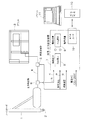
図1は本発明の一実施形態の構成図で、アースオーガ1の先端のビット2から水またはセメントミルクを高圧で噴出させて地盤の掘削と掘削後の地中球根の造成とを行う場合を例示している。
【0011】
アースオーガ1へは、流動物供給源の一例としてのプラント3から流動物としての水またはセメントミルクを同じ液送ライン4(配管系)を使用して供給するようになされており、この液送ライン4中にはその上流側に流量を計測する流量計5(電磁流量計)が、同じく下流側には流体圧力を検出する圧力検出手段としての圧力検出器6がそれぞれ介装されている。
【0012】
前記流量計5からの流量検出信号として瞬時流量aと積算流量bとが流量・圧力記録装置7へ入力され、この流量・圧力記録装置7の瞬時流量表示部9に瞬時流量と積算流量が7セグメント表示により数値表示されるようになっている。
【0013】
これと併せて前記圧力検出器6からの検出圧力値cが流量・圧力記録装置7へ入力され、この流量・圧力記録装置7の瞬時圧力表示部8に瞬時圧力が7セグメント表示により数値表示されるようになっている。
【0014】
一方、上記流量・圧力記録装置7は、ATAカード10(20MB相当)を介してパソコン11に接続され、施工状況、現場名、杭番号、その他の施工記録の保存、解析がなされる。
【0015】
前記圧力検出手段としては、図2に例示するピストン式、図3に例示するダイヤフラム式等の圧力検出器6A,6Bが用いられる。
【0016】
図2にピストン式圧力検出器6Aは、前記液送ライン4を構成する管4aの外側面に設置されて管4a内に開口するケーシング12と、このケーシング12内に液密に摺動自在に嵌挿され受圧面13aが前記管4a内に面しておかれるピストン13と、このピストン13を移動可能に支持し、該ピストン13に背圧を与えるスプリング14を含む支持部15と、このピストン13の移動量を検出してその検出信号を圧力信号として発信する検出器16とで構成されている。
【0017】
一方、切削施工では、概して液送ライン4を流れる流動物の種類(性状)により流動圧力が変わる。例えば、図4に示すように、水を送るときの圧力よりもセメントミルクを送るときの流動圧力の方が高くなる。したがって、ピストン13の受圧面13aに加わる圧力も水とセメントミルクでは異なり、流動物が水である場合はピストン13の移動量は小さく、流動物がセメントミルクである場合はピストン13の移動量が大きくなる。故に、そのピストン13の移動の状態を検出器16で検出することにより、流動物を検知してその流動物が何であるかを知ることができる。
【0018】
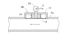
図3のダイヤフラム式圧力検出器6Bは、前記液送ライン4を構成する管4aの外側面に設置されて管4a内に面して開口するハウジング17と、このハウジング17内に張装されたダイヤフラム18と、このダイヤフラム18に背圧を与えるスプリング19と、前記ダイヤフラム18の変位を検知してその検出信号を圧力信号として発信する検出器20とで構成されている。
【0019】
このダイヤフラム式圧力検出器6Bにおいても、液送ライン4を流れる流動物の種類によりダイヤフラム18の変位量が異なることから、現在流れている流動物の流量圧力およびその種類を直ちに知ることができる。
【0020】
したがって例えばアースオーガ1のビット2の先端から水噴射を行いながら地盤の掘削を進め、その掘削深度が支持層に到達したのちそこから所定深さまで掘削した段階で流動物を水からセメントミルクに切り替え、次いでビット2の先端にセメントミルクが達したと判断した時点で所定の速度でビット2の引き上げを開始し、球根を造成して行くが、上記水からセメントミルクへの切り替え後のビット2の引き上げタイミングを圧力検出値を知ることにより正確に把握することができる。
【0021】
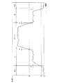
図4は水とセメントミルクとの流量圧力−時間のグラフを示すもので、この図において流量圧力(MPa)=Xが或る範囲内の場合、流量タイプは次のようになる。
【0022】
1)O≦X<A;停止
2)A≦X<B;水
3)B≦X ;セメントミルク
ここで、図4において、液送ライン4に水が流れているときは、しきい値圧力Bより小さい圧力が検知されるが、水からセメントミルクに切り換えると、液送ライン4ではセメントミルクが水を押し出しながら流れ、次第に圧力が上昇していく。しきい値圧力Bを超えて連続してt時間(3秒)経過した後も圧力が上昇していく場合、液送ライン4内は水からセメントミルクに完全に置換され、その時点(しきい値圧力Bを越えた時点から3秒後)でビット2の先端までセメントミルクが達したと判定する。
【0023】
【発明の効果】
以上説明したように本発明によれば、水とセメントミルク供給源と施工現場との距離が離隔している場合、すなわち配管系のライン置換量が大きくとも、ライン圧力をしきい値圧力および時間との関係でみることにより、セメントミルクがビットの先端に達した時間を判定できるので、ビットの引き上げタイミングを的確に把握して行うことができる。
【0024】
また本発明を用いれば、計測に加え品質管理および提出用の記録を同時に行えるようにすることができるので、作業員の削減をも図ることが可能となる。
【0025】
さらに流動物の組成変化が生じ、設定範囲を逸脱した場合に液送中止や修正等の警告や処置をいち早くとることができ、品質劣化を未然に防ぐことにも繋げることができる。
【図面の簡単な説明】
【図1】本発明の一実施形態を示す構成図。
【図2】図1における圧力検出手段の一例としてのピストン式圧力検出器を示す断面図。
【図3】同、ダイヤフラム式圧力検出器を示す断面図。
【図4】流量圧力−時間のグラフ。
【符号の説明】
1 アースオーガ
2 ビット
3 プラント(流動物供給源)
4 液送ライン
5 流量計
6 圧力検出手段(圧力検出器)
6A ピストン式圧力検出器
6B ダイヤフラム式圧力検出器
7 圧力記録装置
12 ケーシング
13 ピストン
16 検出器
17 ハウジング
18 ダイヤフラム
20 検出器[0001]
BACKGROUND OF THE INVENTION
In the present invention, when different types of fluids are fed by the same liquid feed line, the type of the fluid is discriminated in the liquid feed line, and the accurate instruction and quantification to the destination and the recording thereof are performed. The present invention also relates to an automatic recognition method for heterogeneous fluids and an apparatus therefor.
[0002]
[Prior art]
For example, in the construction of foundation piles, the earth and auger equipped with a bit having a high-pressure injection hole at the tip end is used to excavate the soil at the tip of the pile in cooperation with the high-pressure water jetted from the high-pressure injection hole. After reaching the support layer, the construction method is generally employed in which the spray water is switched to cement milk, high-pressure spray is performed at a predetermined pressure, and then a bit is pulled up at a predetermined speed to construct an enlarged bulb having a predetermined diameter and a predetermined strength. .
[0003]
In the above work, when the bit is raised, the work instructor tells the valve switching worker the instruction to switch from water to cement milk, and then the work instructor sends a signal from the valve switching worker that the switch has been completed, Taking into account the amount of residual water, an auger operator has been instructed to raise the bit by an empirical method that the cement milk has reached the tip of the bit.
[0004]
[Problems to be solved by the invention]
However, in the above method, when the distance between the cement milk plant and the construction site is long, that is, when the amount of line replacement is large, it is determined whether cement milk of a predetermined concentration has reached the tip of the bit, in other words, For example, an error may occur frequently in the timing of raising the bit.
[0005]
Also, in order to pull up the bit at a constant speed while maintaining a predetermined diameter (predetermined strength) when pouring cement milk, the voltage drops for some reason, and the cement milk liquid feeding pressure drops (insufficient flow rate). When this occurs, a basic problem in quality control is brought about in that a bulb having a predetermined diameter (predetermined strength) cannot be built.
[0006]
The present invention eliminates the above-mentioned conventional problems, provides an underground composition having a predetermined diameter and a predetermined strength, and enables an automatic recognition method and apparatus for different fluids that enable measurement and recording necessary for quality control. Is to provide.
[0007]
[Means for Solving the Problems]
As a means for solving the above-mentioned problems, the method for automatically recognizing a heterogeneous fluid according to the present invention switches from a source of water and a heterogeneous fluid of cement milk to a fluid of either water or cement milk through the same liquid feed line. The fluid pressure is detected in the middle of the fluid feed line that feeds the fluid to the bit at the tip of the earth auger, and whether the fluid flowing based on the pressure detection signal is water. It is characterized by determining whether it is cement milk .
In addition, the apparatus for automatically recognizing different types of fluids according to the present invention feeds liquids while switching from water and cement milks to different fluids of either water or cement milk through the same liquid feed line. pressure sensing means for detecting the pressure of said one of fluids flowing through the fluid feed liquid feed in line in the middle portion of the line for feeding the liquid to the tip of the bit of the auger is provided, the liquid feed in line by the pressure detection means It is characterized in that a detection signal of the pressure of the flowing fluid is obtained, and whether the flowing fluid is water or cement milk is determined based on the detection signal of the pressure .
[0008]
As the pressure detecting means, a casing that is installed on the outer side of the pipe constituting the liquid feed line and is opened facing the pipe, and a pressure receiving surface that is slidably inserted in the casing faces the pipe. And a support means including a spring that movably supports the piston and applies back pressure to the piston, and a detector that detects the amount of movement of the piston and transmits a detection signal thereof. Piston type or housing installed outside the pipe constituting the liquid feed line and opened facing the pipe, a diaphragm stretched in the housing, a spring for applying a back pressure to the diaphragm, and the diaphragm A diaphragm type composed of a detector that detects the displacement of the sensor and transmits a detection signal thereof can be employed.
[0009]
DETAILED DESCRIPTION OF THE INVENTION
The present invention will be described below with reference to embodiments shown in the drawings.
[0010]
FIG. 1 is a block diagram of an embodiment of the present invention, in which water or cement milk is ejected from a
[0011]
The
[0012]
The instantaneous flow rate a and the integrated flow rate b are input to the flow rate /
[0013]
The detected pressure value c from the
[0014]
On the other hand, the flow rate /
[0015]
As the pressure detection means, piston-
[0016]
In FIG. 2, a piston
[0017]
On the other hand, in cutting work, the flow pressure varies depending on the type (characteristic) of the fluid flowing through the
[0018]
The diaphragm
[0019]
Also in this diaphragm
[0020]
Therefore, for example, while excavating the ground while water is sprayed from the tip of the
[0021]
FIG. 4 shows a graph of flow rate pressure-time of water and cement milk. In this figure, when the flow rate pressure (MPa) = X is within a certain range, the flow type is as follows.
[0022]
1) O ≦ X <A; Stop 2) A ≦ X <B; Water 3) B ≦ X; Cement milk Here, in FIG. 4, when water is flowing in the
[0023]
【The invention's effect】
As described above, according to the present invention, when the distances between the water, the cement milk supply source, and the construction site are separated, that is, even if the line replacement amount of the piping system is large , the line pressure is set to the threshold pressure and time. Since it is possible to determine the time when the cement milk reaches the tip of the bit, it is possible to accurately grasp the timing of lifting the bit.
[0024]
Further, if the present invention is used, quality control and recording for submission can be performed simultaneously in addition to measurement, so that the number of workers can be reduced.
[0025]
Furthermore, when the composition change of the fluid occurs and deviates from the set range, warnings and measures such as suspension of liquid feeding and correction can be taken promptly, leading to prevention of quality deterioration.
[Brief description of the drawings]
FIG. 1 is a configuration diagram showing an embodiment of the present invention.
2 is a cross-sectional view showing a piston-type pressure detector as an example of pressure detecting means in FIG. 1. FIG.
FIG. 3 is a cross-sectional view showing a diaphragm type pressure detector.
FIG. 4 is a graph of flow rate pressure-time.
[Explanation of symbols]
1
4 Liquid feed line 5
6A Piston
Claims (5)
Priority Applications (1)
| Application Number | Priority Date | Filing Date | Title |
|---|---|---|---|
| JP2001283023A JP4570825B2 (en) | 2001-09-18 | 2001-09-18 | Method and apparatus for automatically recognizing different fluids |
Applications Claiming Priority (1)
| Application Number | Priority Date | Filing Date | Title |
|---|---|---|---|
| JP2001283023A JP4570825B2 (en) | 2001-09-18 | 2001-09-18 | Method and apparatus for automatically recognizing different fluids |
Publications (2)
| Publication Number | Publication Date |
|---|---|
| JP2003090042A JP2003090042A (en) | 2003-03-28 |
| JP4570825B2 true JP4570825B2 (en) | 2010-10-27 |
Family
ID=19106582
Family Applications (1)
| Application Number | Title | Priority Date | Filing Date |
|---|---|---|---|
| JP2001283023A Expired - Lifetime JP4570825B2 (en) | 2001-09-18 | 2001-09-18 | Method and apparatus for automatically recognizing different fluids |
Country Status (1)
| Country | Link |
|---|---|
| JP (1) | JP4570825B2 (en) |
Families Citing this family (1)
| Publication number | Priority date | Publication date | Assignee | Title |
|---|---|---|---|---|
| CN114112178A (en) * | 2021-12-24 | 2022-03-01 | 李玉玲 | Column display hydraulic measuring device |
Family Cites Families (1)
| Publication number | Priority date | Publication date | Assignee | Title |
|---|---|---|---|---|
| JP3476166B2 (en) * | 1995-07-18 | 2003-12-10 | 株式会社ジオトップ | Construction management method and device in embedded pile method |
-
2001
- 2001-09-18 JP JP2001283023A patent/JP4570825B2/en not_active Expired - Lifetime
Also Published As
| Publication number | Publication date |
|---|---|
| JP2003090042A (en) | 2003-03-28 |
Similar Documents
| Publication | Publication Date | Title |
|---|---|---|
| US7819189B1 (en) | Method and system for determining plunger location in a plunger lift system | |
| CN102597415B (en) | Monitoring device and method for hydraulic control system | |
| CA2556427A1 (en) | Smooth draw-down for formation pressure testing | |
| AU3390899A (en) | Blood clot detector | |
| CN103184841A (en) | Apparatuses and methods for determining wellbore influx condition using qualitative indications | |
| US5665601A (en) | Avoiding bubble formation while sensing air-liquid interface using pressurized air flow | |
| GB2415213A (en) | Apparatus, system and method to detect actuation of a flow control device | |
| KR102279806B1 (en) | Apparatus for measuring in-situ water pressure in the borehole | |
| US5758538A (en) | Tensiometer and method of determining soil moisture potential in below-grade earthen soil | |
| WO2007084909A1 (en) | Line leak detector | |
| CN109209304A (en) | A kind of well plunger control system | |
| JP4570825B2 (en) | Method and apparatus for automatically recognizing different fluids | |
| CN108226001A (en) | A kind of bicyclic method automatic test device and bicyclic water injection test method | |
| US7596988B2 (en) | High performance liquid chromatography sample introduction optimized with bubble detection | |
| JP2006152594A (en) | Ground injection method | |
| KR101831683B1 (en) | Grouting packer device for a active controlling of underground injection pressure | |
| JP5424685B2 (en) | Conduit deterioration diagnosis facility, conduit deterioration diagnosis method, and valve device | |
| JP2024515328A (en) | Apparatus and method for controlling flashing in rock drilling | |
| US20220082178A1 (en) | Sensing gate valve position | |
| CN108825214B (en) | Well cementation rubber plug positioning system and positioning method thereof | |
| EP3441186B1 (en) | Water jet device with sensor and method for water jet cutting | |
| CN106645596B (en) | Device for detecting grouting quality of prestressed component pore canal and detection method based on device | |
| JPH09111746A (en) | Injection control device | |
| JPH0657934B2 (en) | Water permeability test equipment | |
| JP2007046320A (en) | Grouting apparatus and grouting method |
Legal Events
| Date | Code | Title | Description |
|---|---|---|---|
| A711 | Notification of change in applicant |
Free format text: JAPANESE INTERMEDIATE CODE: A712 Effective date: 20070423 |
|
| A621 | Written request for application examination |
Free format text: JAPANESE INTERMEDIATE CODE: A621 Effective date: 20080425 |
|
| A977 | Report on retrieval |
Free format text: JAPANESE INTERMEDIATE CODE: A971007 Effective date: 20100212 |
|
| A131 | Notification of reasons for refusal |
Free format text: JAPANESE INTERMEDIATE CODE: A131 Effective date: 20100219 |
|
| A521 | Request for written amendment filed |
Free format text: JAPANESE INTERMEDIATE CODE: A523 Effective date: 20100415 |
|
| TRDD | Decision of grant or rejection written | ||
| A01 | Written decision to grant a patent or to grant a registration (utility model) |
Free format text: JAPANESE INTERMEDIATE CODE: A01 Effective date: 20100713 |
|
| A01 | Written decision to grant a patent or to grant a registration (utility model) |
Free format text: JAPANESE INTERMEDIATE CODE: A01 |
|
| A61 | First payment of annual fees (during grant procedure) |
Free format text: JAPANESE INTERMEDIATE CODE: A61 Effective date: 20100811 |
|
| FPAY | Renewal fee payment (event date is renewal date of database) |
Free format text: PAYMENT UNTIL: 20130820 Year of fee payment: 3 |
|
| R150 | Certificate of patent or registration of utility model |
Ref document number: 4570825 Country of ref document: JP Free format text: JAPANESE INTERMEDIATE CODE: R150 Free format text: JAPANESE INTERMEDIATE CODE: R150 |
|
| R250 | Receipt of annual fees |
Free format text: JAPANESE INTERMEDIATE CODE: R250 |
|
| R250 | Receipt of annual fees |
Free format text: JAPANESE INTERMEDIATE CODE: R250 |
|
| R250 | Receipt of annual fees |
Free format text: JAPANESE INTERMEDIATE CODE: R250 |
|
| S111 | Request for change of ownership or part of ownership |
Free format text: JAPANESE INTERMEDIATE CODE: R313121 |
|
| R360 | Written notification for declining of transfer of rights |
Free format text: JAPANESE INTERMEDIATE CODE: R360 |
|
| R370 | Written measure of declining of transfer procedure |
Free format text: JAPANESE INTERMEDIATE CODE: R370 |
|
| S111 | Request for change of ownership or part of ownership |
Free format text: JAPANESE INTERMEDIATE CODE: R313115 |
|
| S533 | Written request for registration of change of name |
Free format text: JAPANESE INTERMEDIATE CODE: R313533 |
|
| R350 | Written notification of registration of transfer |
Free format text: JAPANESE INTERMEDIATE CODE: R350 |
|
| R250 | Receipt of annual fees |
Free format text: JAPANESE INTERMEDIATE CODE: R250 |
|
| R250 | Receipt of annual fees |
Free format text: JAPANESE INTERMEDIATE CODE: R250 |
|
| S531 | Written request for registration of change of domicile |
Free format text: JAPANESE INTERMEDIATE CODE: R313531 |
|
| R350 | Written notification of registration of transfer |
Free format text: JAPANESE INTERMEDIATE CODE: R350 |
|
| R250 | Receipt of annual fees |
Free format text: JAPANESE INTERMEDIATE CODE: R250 |
|
| R250 | Receipt of annual fees |
Free format text: JAPANESE INTERMEDIATE CODE: R250 |
|
| R250 | Receipt of annual fees |
Free format text: JAPANESE INTERMEDIATE CODE: R250 |
|
| R250 | Receipt of annual fees |
Free format text: JAPANESE INTERMEDIATE CODE: R250 |
|
| EXPY | Cancellation because of completion of term |