JP4569698B2 - Object recognition apparatus, object recognition method, and object recognition method program - Google Patents
Object recognition apparatus, object recognition method, and object recognition method program Download PDFInfo
- Publication number
- JP4569698B2 JP4569698B2 JP2008300506A JP2008300506A JP4569698B2 JP 4569698 B2 JP4569698 B2 JP 4569698B2 JP 2008300506 A JP2008300506 A JP 2008300506A JP 2008300506 A JP2008300506 A JP 2008300506A JP 4569698 B2 JP4569698 B2 JP 4569698B2
- Authority
- JP
- Japan
- Prior art keywords
- feature
- feature point
- point
- processing
- target image
- Prior art date
- Legal status (The legal status is an assumption and is not a legal conclusion. Google has not performed a legal analysis and makes no representation as to the accuracy of the status listed.)
- Expired - Fee Related
Links
Images


Classifications
-
- G—PHYSICS
- G06—COMPUTING; CALCULATING OR COUNTING
- G06V—IMAGE OR VIDEO RECOGNITION OR UNDERSTANDING
- G06V10/00—Arrangements for image or video recognition or understanding
- G06V10/70—Arrangements for image or video recognition or understanding using pattern recognition or machine learning
- G06V10/74—Image or video pattern matching; Proximity measures in feature spaces
- G06V10/75—Organisation of the matching processes, e.g. simultaneous or sequential comparisons of image or video features; Coarse-fine approaches, e.g. multi-scale approaches; using context analysis; Selection of dictionaries
- G06V10/757—Matching configurations of points or features
Landscapes
- Engineering & Computer Science (AREA)
- Computer Vision & Pattern Recognition (AREA)
- Theoretical Computer Science (AREA)
- Evolutionary Computation (AREA)
- Computing Systems (AREA)
- Databases & Information Systems (AREA)
- Artificial Intelligence (AREA)
- General Health & Medical Sciences (AREA)
- Medical Informatics (AREA)
- Software Systems (AREA)
- Health & Medical Sciences (AREA)
- Physics & Mathematics (AREA)
- General Physics & Mathematics (AREA)
- Multimedia (AREA)
- Image Analysis (AREA)
Description
本発明は、物体認識装置、物体認識方法、物体認識方法のプログラム及び物体認識方法のプログラムを記録した記録媒体に関し、例えばデータベースに記録した多数の静止画像から特定の被写体を撮影した静止画像を検索する場合に適用することができる。本発明は、モデル画像又は処理対象画像をセグメント化した後、ベース点及び対応するサポート点を同一のセグメントに設定することにより、モデル画像に背景が写っている場合でも、精度の劣化を防止することができるようにする。 The present invention relates to an object recognition device, an object recognition method, a program for the object recognition method, and a recording medium on which the program for the object recognition method is recorded. For example, a still image obtained by photographing a specific subject is searched from a large number of still images recorded in a database. It can be applied to According to the present invention, after the model image or the processing target image is segmented, the base point and the corresponding support point are set to the same segment, thereby preventing deterioration in accuracy even when the model image has a background. To be able to.
近年、電子スチルカメラ等では、テンプレートマッチングの手法を用いた物体認識により、処理対象画像から所望する認識対象物体(以下、モデル物体と呼ぶ)を検出している。このテンプレートマッチングの手法を用いた物体認識は、モデル物体が部分的に隠れている場合、モデル物体の向きが変化している場合、照明が変化している場合等に、十分に対応できない欠点がある。 In recent years, an electronic still camera or the like detects a desired recognition target object (hereinafter referred to as a model object) from a processing target image by object recognition using a template matching technique. The object recognition using this template matching method has a drawback that it cannot be adequately handled when the model object is partially hidden, when the orientation of the model object is changed, or when the illumination is changed. is there.
このような物体認識に関して、特開2004−326693号公報には、モデル物体の局所的な特徴量を用いたマッチングにより物体認識する方法が提案されている。この特開2004−326693号公報に開示の手法によれば、照明の変化による検出精度の低下を低減し、ロバストに物体認識することができる。しかしながらこの方法の場合、モデル物体にテクスチャー成分が少ないと、精度が劣化する欠点がある。 Regarding such object recognition, Japanese Patent Application Laid-Open No. 2004-326693 proposes a method of recognizing an object by matching using a local feature amount of a model object. According to the technique disclosed in Japanese Patent Application Laid-Open No. 2004-326693, a decrease in detection accuracy due to a change in illumination can be reduced, and an object can be recognized robustly. However, in the case of this method, there is a drawback that the accuracy is deteriorated if the model object has few texture components.
また特開2008−77626号公報には、モデル物体のエッジ画像における局所領域内のベース点と、このベース点をサポートするサポート点とを用いたマッチングにより物体認識する方法が提案されている。 Japanese Patent Application Laid-Open No. 2008-77626 proposes a method of recognizing an object by matching using a base point in a local region in an edge image of a model object and a support point that supports the base point.
この特開2008−77626号公報に開示の手法によれば、図36において矢印Aによりモデル画像M1と処理対象画像Lとの関係を示すように、モデル物体MOにテクスチャー成分が少ない場合、処理対象画像Lでモデル物体MOが隠れている場合でも、精度の劣化を防止することができる。なおここでモデル画像は、モデル物体を撮影した処理基準の画像である。
ところでこの種の物体認識を各種のアプリケーションで使用する場合、図35(C)に示すように、モデル画像に背景が写っている場合も予測される。この場合、このモデル画像M2を用いた物体認識では、矢印Bにより関係を示すように、この背景の写ったモデル画像M2中のモデル物体MOを、処理対象画像Lから検出することになる。 By the way, when this kind of object recognition is used in various applications, it is predicted that the model image includes a background as shown in FIG. In this case, in the object recognition using the model image M2, as indicated by the arrow B, the model object MO in the model image M2 in which the background is captured is detected from the processing target image L.
しかしながら従来の物体認識では、モデル画像に背景が写っている場合、精度が著しく劣化する問題がある。 However, in the conventional object recognition, there is a problem that the accuracy is remarkably deteriorated when the background is reflected in the model image.
本発明は以上の点を考慮してなされたもので、モデル画像に背景が写っている場合でも、精度の劣化を防止することができる物体認識装置、物体認識方法、物体認識方法のプログラム及び物体認識方法のプログラムを記録した記録媒体を提案しようとするものである。 The present invention has been made in consideration of the above points. An object recognition apparatus, an object recognition method, a program for an object recognition method, and an object capable of preventing deterioration in accuracy even when a background is reflected in a model image. The present invention intends to propose a recording medium on which a recognition method program is recorded.
上記の課題を解決するため本発明のある観点においては、物体認識装置に適用して、モデル画像を処理するモデル画像処理部と、処理対象画像を処理する処理対象画像処理部と、前記モデル画像処理部及び処理対象画像処理部の処理結果をマッチング処理するマッチング部と、前記マッチング部の処理結果を判定して、前記処理対象画像中のモデル物体の有無を判定する判定部とを有するようにする。ここで前記モデル画像処理部は、前記モデル画像に、ベース点と前記ベース点をサポートするサポート点とによる特徴点セットを設定し、前記特徴点セットの特徴量を検出する特徴点セット決定部を有するようにする。前記処理対象画像処理部は、前記処理対象画像に、特徴点を設定して特徴量を検出する特徴点設定部を有するようにする。前記マッチング部は、前記モデル画像に設定された前記特徴点セットの特徴量と、前記処理対象画像に設定された前記特徴点の特徴量との比較により、前記特徴点セットに対応する前記特徴点を検出して前記マッチング処理を実行する。前記モデル画像処理部は、前記モデル画像をセグメント化するセグメンテーション部を有し、前記特徴点セット決定部は、前記モデル画像のセグメント毎に、前記ベース点及び対応するサポート点を同一のセグメントに設定して前記特徴点セットを設定する。 In order to solve the above problems, in an aspect of the present invention, a model image processing unit that processes a model image, a processing target image processing unit that processes a processing target image, and the model image applied to an object recognition device A matching unit that performs a matching process on the processing results of the processing unit and the processing target image processing unit, and a determination unit that determines the processing result of the matching unit and determines the presence or absence of a model object in the processing target image. To do. Here, the model image processing unit sets a feature point set based on a base point and a support point that supports the base point in the model image, and detects a feature point set determining unit that detects a feature amount of the feature point set. To have. The processing target image processing unit includes a feature point setting unit that sets feature points in the processing target image and detects a feature amount. The matching unit compares the feature amount of the feature point set set in the model image with the feature amount of the feature point set in the processing target image, and the feature point corresponding to the feature point set And the matching process is executed. The model image processing unit includes a segmentation unit that segments the model image, and the feature point set determination unit sets the base point and the corresponding support point to the same segment for each segment of the model image Then, the feature point set is set.
また本発明の別の観点においては、物体認識装置に適用して、モデル画像を処理するモデル画像処理部と、処理対象画像を処理する処理対象画像処理部と、前記モデル画像処理部及び処理対象画像処理部の処理結果をマッチング処理するマッチング部と、前記マッチング部の処理結果を判定して、前記処理対象画像中のモデル物体の有無を判定する判定部とを有するようにする。ここで前記処理対象画像処理部は、前記処理対象画像に、ベース点と前記ベース点をサポートするサポート点とによる特徴点セットを設定し、前記特徴点セットの特徴量を検出する特徴点セット決定部を有するようにする。前記モデル画像処理部は、前記モデル画像に、特徴点を設定して特徴量を検出する特徴点設定部を有するようにする。前記マッチング部は、前記処理対象画像に設定された前記特徴点セットの特徴量と、前記モデル画像に設定された前記特徴点の特徴量との比較により、前記特徴点セットに対応する前記特徴点を検出して前記マッチング処理を実行する。前記処理対象画像処理部は、前記処理対象画像をセグメント化するセグメンテーション部を有し、前記特徴点セット決定部は、前記処理対象画像のセグメント毎に、前記ベース点及び対応するサポート点を同一のセグメントに設定して前記特徴点セットを設定する。 In another aspect of the present invention, a model image processing unit for processing a model image, a processing target image processing unit for processing a processing target image, the model image processing unit, and a processing target, which are applied to an object recognition device. A matching unit that performs a matching process on the processing result of the image processing unit, and a determination unit that determines the processing result of the matching unit and determines the presence or absence of the model object in the processing target image. Here, the processing target image processing unit sets a feature point set based on a base point and a support point that supports the base point in the processing target image, and detects a feature amount of the feature point set. To have a part. The model image processing unit includes a feature point setting unit that sets feature points in the model image and detects feature amounts. The matching unit compares the feature amount of the feature point set set in the processing target image with the feature amount of the feature point set in the model image, and the feature point corresponding to the feature point set And the matching process is executed. The processing target image processing unit includes a segmentation unit that segments the processing target image, and the feature point set determination unit sets the same base point and corresponding support point for each segment of the processing target image. The feature point set is set for the segment.
また本発明の別の観点においては、物体認識方法に適用して、モデル画像を処理するモデル画像処理ステップと、処理対象画像を処理する処理対象画像処理ステップと、前記モデル画像処理ステップ及び処理対象画像処理ステップの処理結果をマッチング処理するマッチングステップと、前記マッチングステップの処理結果を判定して、前記処理対象画像中のモデル物体の有無を判定する判定ステップとを有するようにする。ここで前記モデル画像処理ステップは、前記モデル画像に、ベース点と前記ベース点をサポートするサポート点とによる特徴点セットを設定し、前記特徴点セットの特徴量を検出する特徴点セット決定ステップを有するようにする。前記処理対象画像処理ステップは、前記処理対象画像に、特徴点を設定して特徴量を検出する特徴点設定ステップを有するようにする。前記マッチングステップは、前記モデル画像に設定された前記特徴点セットの特徴量と、前記処理対象画像に設定された前記特徴点の特徴量との比較により、前記特徴点セットに対応する前記特徴点を検出して前記マッチング処理を実行する。前記モデル画像処理ステップは、前記モデル画像をセグメント化するセグメンテーションステップを有し、前記特徴点セット決定ステップは、前記モデル画像のセグメント毎に、前記ベース点及び対応するサポート点を同一のセグメントに設定して前記特徴点セットを設定する。 In another aspect of the present invention, a model image processing step for processing a model image applied to an object recognition method, a processing target image processing step for processing a processing target image, the model image processing step and the processing target A matching step for performing a matching process on the processing result of the image processing step and a determination step for determining the presence or absence of a model object in the processing target image by determining the processing result of the matching step. The model image processing step includes a feature point set determination step of setting a feature point set by a base point and a support point supporting the base point in the model image, and detecting a feature amount of the feature point set. To have. The processing target image processing step includes a feature point setting step of setting a feature point in the processing target image and detecting a feature amount. In the matching step, the feature point corresponding to the feature point set is compared with a feature amount of the feature point set set in the model image and a feature amount of the feature point set in the processing target image. And the matching process is executed. The model image processing step includes a segmentation step for segmenting the model image, and the feature point set determining step sets the base point and the corresponding support point to the same segment for each segment of the model image. Then, the feature point set is set.
また本発明の別の観点においては、物体認識方法に適用して、モデル画像を処理するモデル画像処理ステップと、処理対象画像を処理する処理対象画像処理ステップと、前記モデル画像処理ステップ及び処理対象画像処理ステップの処理結果をマッチング処理するマッチングステップと、前記マッチングステップの処理結果を判定して、前記処理対象画像中のモデル物体の有無を判定する判定ステップとを有するようにする。ここで前記処理対象画像処理ステップは、前記処理対象画像に、ベース点と前記ベース点をサポートするサポート点とによる特徴点セットを設定し、前記特徴点セットの特徴量を検出する特徴点セット決定ステップを有するようにする。前記モデル画像処理ステップは、前記モデル画像に、特徴点を設定して特徴量を検出する特徴点設定ステップを有するようにする。前記マッチングステップは、前記処理対象画像に設定された前記特徴点セットの特徴量と、前記モデル画像に設定された前記特徴点の特徴量との比較により、前記特徴点セットに対応する前記特徴点を検出して前記マッチング処理を実行する。前記処理対象画像処理ステップは、前記処理対象画像をセグメント化するセグメンテーションステップを有し、前記特徴点セット決定ステップは、前記処理対象画像のセグメント毎に、前記ベース点及び対応するサポート点を同一のセグメントに設定して前記特徴点セットを設定する。 In another aspect of the present invention, a model image processing step for processing a model image applied to an object recognition method, a processing target image processing step for processing a processing target image, the model image processing step and the processing target A matching step for performing a matching process on the processing result of the image processing step and a determination step for determining the presence or absence of a model object in the processing target image by determining the processing result of the matching step. Here, the processing target image processing step sets a feature point set based on a base point and a support point that supports the base point in the processing target image, and detects a feature amount of the feature point set. To have steps. The model image processing step includes a feature point setting step of detecting a feature amount by setting a feature point in the model image. In the matching step, the feature point corresponding to the feature point set is compared with the feature amount of the feature point set set in the processing target image and the feature amount of the feature point set in the model image. And the matching process is executed. The processing target image processing step includes a segmentation step for segmenting the processing target image, and the feature point set determination step sets the base point and the corresponding support point to the same for each segment of the processing target image. The feature point set is set for the segment.
また本発明の別の観点においては、物体認識方法のプログラムに適用して、モデル画像を処理するモデル画像処理ステップと、処理対象画像を処理する処理対象画像処理ステップと、前記モデル画像処理ステップ及び処理対象画像処理ステップの処理結果をマッチング処理するマッチングステップと、前記マッチングステップの処理結果を判定して、前記処理対象画像中のモデル物体の有無を判定する判定ステップとを有するようにする。ここで前記モデル画像処理ステップは、前記モデル画像に、ベース点と前記ベース点をサポートするサポート点とによる特徴点セットを設定し、前記特徴点セットの特徴量を検出する特徴点セット決定ステップを有するようにする。前記処理対象画像処理ステップは、前記処理対象画像に、特徴点を設定して特徴量を検出する特徴点設定ステップを有するようにする。前記マッチングステップは、前記モデル画像に設定された前記特徴点セットの特徴量と、前記処理対象画像に設定された前記特徴点の特徴量との比較により、前記特徴点セットに対応する前記特徴点を検出して前記マッチング処理を実行する。前記モデル画像処理ステップは、前記モデル画像をセグメント化するセグメンテーションステップを有し、前記特徴点セット決定ステップは、前記モデル画像のセグメント毎に、前記ベース点及び対応するサポート点を同一のセグメントに設定して前記特徴点セットを設定する。 Further , in another aspect of the present invention, a model image processing step for processing a model image, a processing target image processing step for processing a processing target image, the model image processing step, A matching step for matching the processing result of the processing target image processing step and a determination step for determining the processing result of the matching step to determine the presence or absence of a model object in the processing target image are provided. The model image processing step includes a feature point set determination step of setting a feature point set by a base point and a support point supporting the base point in the model image, and detecting a feature amount of the feature point set. To have. The processing target image processing step includes a feature point setting step of setting a feature point in the processing target image and detecting a feature amount. In the matching step, the feature point corresponding to the feature point set is compared with a feature amount of the feature point set set in the model image and a feature amount of the feature point set in the processing target image. And the matching process is executed. The model image processing step includes a segmentation step for segmenting the model image, and the feature point set determining step sets the base point and the corresponding support point to the same segment for each segment of the model image. Then, the feature point set is set.
また本発明の別の観点においては、物体認識方法のプログラムに適用して、モデル画像を処理するモデル画像処理ステップと、処理対象画像を処理する処理対象画像処理ステップと、前記モデル画像処理ステップ及び処理対象画像処理ステップの処理結果をマッチング処理するマッチングステップと、前記マッチングステップの処理結果を判定して、前記処理対象画像中のモデル物体の有無を判定する判定ステップとを有するようにする。ここで前記処理対象画像処理ステップは、前記処理対象画像に、ベース点と前記ベース点をサポートするサポート点とによる特徴点セットを設定し、前記特徴点セットの特徴量を検出する特徴点セット決定ステップを有するようにする。前記モデル画像処理ステップは、前記モデル画像に、特徴点を設定して特徴量を検出する特徴点設定ステップを有するようにする。前記マッチングステップは、前記処理対象画像に設定された前記特徴点セットの特徴量と、前記モデル画像に設定された前記特徴点の特徴量との比較により、前記特徴点セットに対応する前記特徴点を検出して前記マッチング処理を実行する。前記処理対象画像処理ステップは、前記処理対象画像をセグメント化するセグメンテーションステップを有し、前記特徴点セット決定ステップは、前記処理対象画像のセグメント毎に、前記ベース点及び対応するサポート点を同一のセグメントに設定して前記特徴点セットを設定する。 Further , in another aspect of the present invention, a model image processing step for processing a model image, a processing target image processing step for processing a processing target image, the model image processing step, A matching step for matching the processing result of the processing target image processing step and a determination step for determining the processing result of the matching step to determine the presence or absence of a model object in the processing target image are provided. Here, the processing target image processing step sets a feature point set based on a base point and a support point that supports the base point in the processing target image, and detects a feature amount of the feature point set. To have steps. The model image processing step includes a feature point setting step of detecting a feature amount by setting a feature point in the model image. In the matching step, the feature point corresponding to the feature point set is compared with the feature amount of the feature point set set in the processing target image and the feature amount of the feature point set in the model image. And the matching process is executed. The processing target image processing step includes a segmentation step for segmenting the processing target image, and the feature point set determination step sets the base point and the corresponding support point to the same for each segment of the processing target image. The feature point set is set for the segment.
また上記課題を解決するために、本発明の別の観点によれば、物体認識方法のプログラムを記録した記録媒体に適用して、物体認識方法のプログラムは、モデル画像を処理するモデル画像処理ステップと、処理対象画像を処理する処理対象画像処理ステップと、前記モデル画像処理ステップ及び処理対象画像処理ステップの処理結果をマッチング処理するマッチングステップと、前記マッチングステップの処理結果を判定して、前記処理対象画像中のモデル物体の有無を判定する判定ステップとを有するようにする。ここで前記モデル画像処理ステップは、前記モデル画像に、ベース点と前記ベース点をサポートするサポート点とによる特徴点セットを設定し、前記特徴点セットの特徴量を検出する特徴点セット決定ステップを有するようにする。前記処理対象画像処理ステップは、前記処理対象画像に、特徴点を設定して特徴量を検出する特徴点設定ステップを有するようにする。前記マッチングステップは、前記モデル画像に設定された前記特徴点セットの特徴量と、前記処理対象画像に設定された前記特徴点の特徴量との比較により、前記特徴点セットに対応する前記特徴点を検出して前記マッチング処理を実行する。前記モデル画像処理ステップは、前記モデル画像をセグメント化するセグメンテーションステップを有し、前記特徴点セット決定ステップは、前記モデル画像のセグメント毎に、前記ベース点及び対応するサポート点を同一のセグメントに設定して前記特徴点セットを設定する。
In order to solve the above-described problem, according to another aspect of the present invention, a program for an object recognition method is applied to a recording medium on which a program for an object recognition method is recorded. A processing target image processing step for processing the processing target image, a matching step for matching processing results of the model image processing step and the processing target image processing step, and a processing result of the matching step to determine the processing A determination step of determining the presence or absence of a model object in the target image. The model image processing step includes a feature point set determination step of setting a feature point set by a base point and a support point supporting the base point in the model image, and detecting a feature amount of the feature point set. To have. The processing target image processing step includes a feature point setting step of setting a feature point in the processing target image and detecting a feature amount. In the matching step, the feature point corresponding to the feature point set is compared with a feature amount of the feature point set set in the model image and a feature amount of the feature point set in the processing target image. And the matching process is executed. The model image processing step includes a segmentation step for segmenting the model image, and the feature point set determining step sets the base point and the corresponding support point to the same segment for each segment of the model image. Then, the feature point set is set.
また上記課題を解決するために、本発明の別の観点によれば、物体認識方法のプログラムを記録した記録媒体に適用して、物体認識方法のプログラムは、モデル画像を処理するモデル画像処理ステップと、処理対象画像を処理する処理対象画像処理ステップと、前記モデル画像処理ステップ及び処理対象画像処理ステップの処理結果をマッチング処理するマッチングステップと、前記マッチングステップの処理結果を判定して、前記処理対象画像中のモデル物体の有無を判定する判定ステップとを有するようにする。ここで前記処理対象画像処理ステップは、前記処理対象画像に、ベース点と前記ベース点をサポートするサポート点とによる特徴点セットを設定し、前記特徴点セットの特徴量を検出する特徴点セット決定ステップを有するようにする。前記モデル画像処理ステップは、前記モデル画像に、特徴点を設定して特徴量を検出する特徴点設定ステップを有するようにする。前記マッチングステップは、前記処理対象画像に設定された前記特徴点セットの特徴量と、前記モデル画像に設定された前記特徴点の特徴量との比較により、前記特徴点セットに対応する前記特徴点を検出して前記マッチング処理を実行する。前記処理対象画像処理ステップは、前記処理対象画像をセグメント化するセグメンテーションステップを有し、前記特徴点セット決定ステップは、前記処理対象画像のセグメント毎に、前記ベース点及び対応するサポート点を同一のセグメントに設定して前記特徴点セットを設定する。
In order to solve the above-described problem, according to another aspect of the present invention, a program for an object recognition method is applied to a recording medium on which a program for an object recognition method is recorded. A processing target image processing step for processing the processing target image, a matching step for matching processing results of the model image processing step and the processing target image processing step, and a processing result of the matching step to determine the processing A determination step of determining the presence or absence of a model object in the target image. Here, the processing target image processing step sets a feature point set based on a base point and a support point that supports the base point in the processing target image, and detects a feature amount of the feature point set. To have steps. The model image processing step includes a feature point setting step of detecting a feature amount by setting a feature point in the model image. In the matching step, the feature point corresponding to the feature point set is compared with the feature amount of the feature point set set in the processing target image and the feature amount of the feature point set in the model image. And the matching process is executed. The processing target image processing step includes a segmentation step for segmenting the processing target image, and the feature point set determination step sets the base point and the corresponding support point to the same for each segment of the processing target image. The feature point set is set for the segment.
上述したうちのモデル画像にベース点とサポート点とによる特徴点セットを設定する構成によれば、この特徴点セットの局所特徴量を基準にしてマッチング処理することができる。従ってモデル物体にテクスチャー成分が少ない場合でも、ロバストに認識処理することができる。またベース点及び対応するサポート点を同一のセグメントに設定して特徴点セットを設定することから、背景とモデル物体とにまたがってベース点及びサポート点を設定しないようにすることができる。従って背景とモデル物体とにまたがってベース点及びサポート点を設定することによる認識精度の劣化を防止することができる。 According to the configuration in which the feature point set including the base point and the support point is set in the model image described above, the matching process can be performed based on the local feature amount of the feature point set. Therefore, even when the model object has few texture components, the recognition process can be performed robustly. Further, since the base point and the corresponding support point are set to the same segment and the feature point set is set, it is possible to prevent the base point and the support point from being set across the background and the model object. Accordingly, it is possible to prevent deterioration in recognition accuracy caused by setting the base point and the support point across the background and the model object.
あるいは、上述したうちの処理対象画像にベース点とサポート点とによる特徴点セットを設定する構成によれば、この特徴点セットの局所特徴量を基準にしてマッチング処理することができる。従って処理対象画像のモデル物体にテクスチャー成分が少ない場合でも、ロバストに認識処理することができる。またベース点及び対応するサポート点を同一のセグメントに設定して特徴点セットを設定することから、背景とモデル物体とにまたがってベース点及びサポート点を設定しないようにすることができる。従って背景とモデル物体とにまたがってベース点及びサポート点を設定することによる認識精度の劣化を防止することができる。
Or according to the structure which sets the feature point set by a base point and a support point to the process target image mentioned above, a matching process can be performed on the basis of the local feature-value of this feature point set. Therefore, even when there are few texture components in the model object of the processing target image, robust recognition processing can be performed. Further, since the base point and the corresponding support point are set to the same segment and the feature point set is set, it is possible to prevent the base point and the support point from being set across the background and the model object. Accordingly, it is possible to prevent deterioration in recognition accuracy caused by setting the base point and the support point across the background and the model object.
本発明によれば、モデル画像に背景が写っている場合でも、精度の劣化を防止することができる。 According to the present invention, it is possible to prevent deterioration in accuracy even when a background is reflected in a model image.
以下、適宜図面を参照しながら本発明の実施例を詳述する。
1.第1の実施の形態
2.第2の実施の形態
3.第3の実施の形態
4.第4の実施の形態
5.変形例
<第1の実施の形態>
〔全体構成〕
図2は、本発明の第1の実施の形態の物体認識装置を示す機能ブロック図である。この物体認識装置1は、例えばデータベースに記録した多数の静止画像による自然画からユーザーの操作によりモデル画像の選択を受け付ける。物体認識装置1は、ユーザーにより指定された検索範囲の自然画を処理対象画像(以下、クエリ画像と呼ぶ)に順次設定し、処理対象画像からモデル画像中のモデル物体を検出する。
Hereinafter, embodiments of the present invention will be described in detail with reference to the drawings as appropriate.
1.
〔overall structure〕
FIG. 2 is a functional block diagram illustrating the object recognition apparatus according to the first embodiment of this invention. For example, the
物体認識装置1は、多数の自然画を格納可能な記録装置を有するコンピュータであり、このコンピュータに設けられた中央処理ユニットによる物体認識プログラムの実行により、この図2に示す機能ブロックが構成される。なおこの物体認識プログラムは、事前に、物体認識装置1にインストールして提供される。しかしながら物体認識プログラムは、光ディスク、磁気ディスク、メモリカード等の各種記録媒体に記録して提供してもよく、インターネット等のネットワークを介して提供してもよい。
The
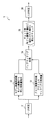
物体認識装置1において、モデル画像処理部2及びクエリ画像処理部3は、それぞれモデル画像及びクエリ画像を処理して処理結果を出力する。マッチング部4は、これらモデル画像処理部2及びクエリ画像処理部3の処理結果に基づいてマッチング処理を実行し、判定部5は、このマッチング部4の処理結果に基づいて、判定結果を出力する。
In the
〔モデル画像の処理〕
図1は、モデル画像処理部2を詳細に示すブロック図である。このモデル画像処理部2において、モデル画像入力部11は、ユーザーの操作により図示しない記録手段に記録された多数の自然画からモデル画像Mの選択を受け付ける。
[Model image processing]
FIG. 1 is a block diagram showing the model
多重解像度部12は、モデル画像Mの解像度を可変し、サンプリング数が順次段階的に変化する複数のモデル画像を生成する。これにより多重解像度部12は、処理対象画像におけるモデル物体のスケール変化に対応可能に、入力されたモデル画像の画サイズを拡大、縮小したピラミット構造によるモデル画像を生成する。なおこの解像度の変換処理は、例えば所定のフィルタを用いたフィルタリング処理により実行される。
The
セグメンテーション部13は、多重解像度部12で生成した各解像度のモデル画像をそれぞれセグメンテーションする。具体的に、セグメンテーション部13は、色を基準にしたセグメンテーションであるカラーセグメンテーションによりモデル画像をセグメント化する。なおカラーセグメンテーションは、種々の手法を適用することができるものの、この実施の形態では、CVPR1999 Y. Deng, B.S. Manjunath, and H. Shin, Color image segmentation に開示の手法により実行する。
The
なおセグメンテーションは、カラーセグメンテーションに限らず、種々の手法を広く適用できる。従って例えば輝度レベル、周波数成分等を基準にして、又はこれらの基準の組み合わせを基準にしてモデル画像をセグメント化してもよい。因みに輝度レベル、周波数成分を基準にしたセグメンテーションは、それぞれ各画素の輝度レベル、各画素の周波数成分を複数の判定基準値で判定してセグメント化する処理である。 The segmentation is not limited to color segmentation, and various methods can be widely applied. Thus, for example, the model image may be segmented on the basis of the luminance level, frequency component, etc., or on the basis of a combination of these criteria. Incidentally, the segmentation based on the luminance level and the frequency component is a process of segmenting the luminance level of each pixel and the frequency component of each pixel by using a plurality of determination reference values.
このセグメンテーションの処理において、セグメンテーション部13は、セグメント間に所定画素幅(例えば1画素幅)のセグメント境界を設定する。
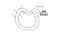
In this segmentation process, the
特徴点抽出部14は、各解像度のモデル画像に設定されたセグメント毎に、セグメント境界上に特徴点を順次設定し、各特徴点の特徴量を検出する。より具体的に、特徴点抽出部14は、図3に示すように、セグメント毎に、セグメント境界上に、一定の間隔で特徴点Pを設定する。従ってこの場合、物体認識装置1は、セグメントの面積及びセグメントの周囲長が小さくなるに従って、1つのセグメントに設定する特徴点数が低減することになり、後述する特徴点セットの数が低下することになる。これによりこの物体認識装置1は、精度の劣化を防止しつつ、以降の無駄な処理を省略して全体の処理を簡略化することができる。
The feature
なおこの一定の間隔による特徴点Pの設定に代えて、セグメント境界上にランダムに所定個数の特徴点を配置するようにしてもよい。なおこの場合には、セグメントの面積及び又はセグメントの周囲長が小さくなるに従って、ランダムに配置する特徴点数を低減することにより特徴点セットの数を低減し、精度の劣化を防止しつつ、以降の無駄な処理を省略して全体の処理を簡略化することができる。 Note that a predetermined number of feature points may be randomly arranged on the segment boundary instead of setting the feature points P at a certain interval. In this case, as the area of the segment and / or the peripheral length of the segment becomes smaller, the number of feature points to be randomly arranged is reduced to reduce the number of feature point sets and prevent deterioration in accuracy. The useless processing can be omitted and the entire processing can be simplified.
特徴点抽出部14は、さらに特徴点P毎に、セグメント境界線の法線上であって、対応する特徴点Pから特徴量記述半径に応じたオフセット距離だけセグメント内に、特徴量記述中心Oを設定する。ここで特徴量記述中心Oは、対応する特徴点の局所領域を定義する基準位置である。この実施の形態では、この特徴量記述中心Oを中心とした円形形状の領域が、対応する特徴点の局所領域に設定され、この円形形状の局所領域から対応する特徴点の特徴量を求める。
The feature
特徴量記述半径は、この円形形状の領域の半径である。この実施の形態において特徴量記述半径は、値が一定の標準値が適用されるものの、モデル画像毎に、セグメント毎に、及び又はセグメントの部位毎に、セグメント境界情報に応じて設定するようにしてもよい。なおこの設定は、例えばセグメント境界上の各部位において、一定領域内に含まれるセグメント境界情報を評価する評価値を求め、この評価値に基づいてこのセグメント境界情報がマッチング処理に有意である程、小さくなるように半径を設定して実行される。 The feature description radius is the radius of this circular region. In this embodiment, the feature value description radius is set according to the segment boundary information for each model image, for each segment, and / or for each segment part, although a standard value with a constant value is applied. May be. In addition, this setting calculates | requires the evaluation value which evaluates the segment boundary information contained in a fixed area | region, for example in each site | part on a segment boundary, Based on this evaluation value, this segment boundary information is so significant for a matching process, It is executed with the radius set to be smaller.
オフセット距離は、この特徴量記述半径より小さな値に設定され、この実施の形態では特徴量記述半径の2/3の値に設定される。 The offset distance is set to a value smaller than the feature amount description radius. In this embodiment, the offset distance is set to a value that is 2/3 of the feature amount description radius.
なおこのように特徴点Pを始めに設定した後、特徴量記述中心Oを設定する代わりに、特徴量記述中心Oを始めに設定した後、対応する特徴点Pを設定するようにしてもよい。この場合、図3との対比により図4に示すように、各セグメントをオフセット距離だけシュリンクし、このオフセット距離だけ対応するセグメントの外側を削り取った特徴量記述中心の設定用領域を形成する。続いてこの特徴量記述中心の設定用領域の外周に、一定の間隔で特徴量記述中心Oを設定する。従ってこの場合、セグメントの面積及びセグメントの周囲長が小さくなるに従って、1つのセグメントに設定する特徴量記述中心Oが低減し、対応する特徴点数も低減することになる。従ってその結果、1つのセグメントに設定する特徴点セットの数も低下することになり、精度の劣化を防止しつつ、以降の無駄な処理を省略して全体の処理を簡略化することができる。 Instead of setting the feature amount description center O after setting the feature point P first in this way, the corresponding feature point P may be set after setting the feature amount description center O first. . In this case, as shown in FIG. 4 in comparison with FIG. 3, each segment is shrunk by the offset distance, and the setting area of the feature description center is formed by scraping the outside of the segment corresponding to this offset distance. Subsequently, feature quantity description centers O are set at regular intervals on the outer periphery of the feature quantity description center setting area. Therefore, in this case, as the area of the segment and the peripheral length of the segment become smaller, the feature amount description center O set for one segment is reduced, and the corresponding feature points are also reduced. Therefore, as a result, the number of feature point sets to be set for one segment also decreases, and it is possible to simplify the entire process by omitting unnecessary processes thereafter while preventing deterioration in accuracy.
なおこの一定の間隔による特徴量記述中心Oの設定に代えて、ランダムに所定個数の特徴量記述中心Oを配置するようにしてもよい。なおこの場合には、セグメントの面積及び又はセグメントの周囲長が小さくなるに従って配置する特徴点数を低減することにより、精度の劣化を防止しつつ、以降の無駄な処理を省略して処理を簡略化することができる。 Note that a predetermined number of feature quantity description centers O may be arranged at random instead of setting the feature quantity description centers O at regular intervals. In this case, the number of feature points to be arranged is reduced as the area of the segment and / or the peripheral length of the segment decreases, thereby preventing the deterioration of accuracy and simplifying the process by omitting unnecessary processes. can do.
続いて各特徴量記述中心からこの設定用領域の外側に向かって、設定用領域の輪郭線の法線を設定し、この法線とセグメント境界との交点を特徴点Pに設定する。 Subsequently, the normal line of the outline of the setting area is set from each feature amount description center to the outside of the setting area, and the intersection of the normal line and the segment boundary is set as the feature point P.
なおこの法線とセグメント境界との交点を特徴点Pに設定する代わりに、各特徴量記述中心から最も近いセグメント境界線上の点を特徴点Pに設定するようにしてもよい。この場合には、必要に応じて各特徴点から特徴量記述中心Oを設定し直すようにしてもよい。 Instead of setting the intersection of the normal line and the segment boundary as the feature point P, a point on the segment boundary line closest to each feature amount description center may be set as the feature point P. In this case, the feature amount description center O may be reset from each feature point as necessary.
なお例えば図5に示すように、オフセット距離の2倍より幅狭の部位を有するセグメントは、特徴量記述中心の設定用領域を設定する際のシュリンクによりこの幅狭の部位が削り取られ、この幅狭の部位には特徴量記述中心の設定用領域を設定できなくなる。その結果、この幅狭の部位には特徴点Pを設定できなくなる。 For example, as shown in FIG. 5, in a segment having a part narrower than twice the offset distance, the narrow part is scraped off by shrink when setting the setting region of the feature description center, and the width It is impossible to set the setting region for the feature description center in the narrow part. As a result, the feature point P cannot be set in this narrow portion.
そこで図5との対比により図6に示すように、セグメントを細線化し、この細線化して作成される領域と、シュリンクにより形成される領域とを重ね合わせて特徴量記述中心の設定用領域としてもよい。なおこの場合、少なくとも幅狭の部位については、必要に応じて特徴点Pを設定した後、特徴量記述中心Oを設定し直す。 Therefore, as shown in FIG. 6 in comparison with FIG. 5, the segment is thinned, and the region created by thinning and the region formed by shrinking are overlapped to serve as the setting region for the feature description center. Good. In this case, at least for the narrow part, after setting the feature point P as necessary, the feature amount description center O is reset.
なおこのように特徴量記述中心Oを、特徴点位置からセグメント内側方向にオフセット距離だけずらすのは、そのセグメントがモデル物体のセグメントで、かつそのセグメントの境界が背景との境界である場合に、マッチング処理の際の背景の影響を低減し、マッチング精度を向上させるためである。従って実用上十分なマッチング精度を確保できる場合には、特徴量記述中心Oを特徴点Pに設定するようにしてもよい。 It should be noted that the feature amount description center O is shifted from the feature point position in the segment inward direction by an offset distance when the segment is a segment of the model object and the boundary of the segment is a boundary with the background. This is because the influence of the background during the matching process is reduced and the matching accuracy is improved. Therefore, when a matching accuracy sufficient for practical use can be ensured, the feature amount description center O may be set to the feature point P.
続いて特徴点抽出部14は、各特徴点の特徴量を検出する。ここで特徴点抽出部14は、特徴量記述中心Oを中心とした特徴量記述半径による円形形状の領域を、対応する特徴点の局所領域とする。特徴点抽出部14は、この局所領域で検出される特徴量を対応する特徴点の特徴量に設定する。
Subsequently, the feature
特徴点抽出部14は、この局所領域に含まれるセグメント境界情報により特徴量を検出し、モデル物体にテクスチャー成分が少ない場合でも十分なマッチング精度を確保できるようにする。なお実用上十分にマッチング精度を確保できる場合には、例えばセグメント境界情報に代えてエッジ情報により特徴量を検出する場合、局所領域の周波数成分により特徴量を検出する場合等、種々の手法により検出される特徴量を広く適用することができる。
The feature
より具体的に、特徴点抽出部14は、局所領域を分割して形成される微小領域毎にセグメント境界情報を集計して特徴量を検出する。この実施の形態では、図7に示すように、局所領域を半径方向及び円周方向に分割してこの微小領域を形成する。なおこの図7は、局所領域を半径方向に3等分して分割し、さらに円周方向に8等分して分割した例である。ここで分割数は、必要に応じて種々に設定することができ、さらに実用上十分なマッチング精度を確保できる場合には、半径方向のみにより、又は円周方向のみにより局所領域を分割して微小領域を形成してもよい。
More specifically, the feature
続いて特徴点抽出部14は、図7との対比により図8及び図9に示すように、微小領域によりセグメント境界点の個数をヒストグラム化し、特徴量記述中心Oから見た角度θ及び距離rによる2次元のヒストグラム(図9)を作成する。特徴点抽出部14は、この2次元のヒストグラムにより各特徴点の特徴量を検出する。なおここでセグメント境界点は、セグメント境界上の連続する画素又はセグメント境界上の一定ピッチによる画素である。図9では、分布が最も大きな微小領域を黒塗りにより示し、また続いて分布が大きな微小領域をハッチングにより示し、分布が0の微小領域を白塗りにより示す。
Subsequently, as shown in FIGS. 8 and 9, the feature
従ってこの場合、セグメント境界情報としてセグメント境界点の位置情報を用いて各特徴点の特徴量を求めることになる。しかしながらセグメント境界情報を用いて特徴量を検出する場合は、これに限らず、例えばセグメント境界点の位置情報と、セグメント境界を特徴付けるパラメータとにより各特徴点の特徴量を求めるようにしてもよい。なおこの場合、例えばセグメント境界点の個数に代えて、各セグメント境界点におけるパラメータを各微小領域で集計してヒストグラム化することにより、特徴量を検出することができる。なおこのパラメータとしては、例えばセグメント境界を垂直に横切る方向の画素値の勾配値を適用することができる。またエッジ情報を用いて特徴量を検出する場合は、エッジ上の点を同様に領域毎に集計して、又はエッジを特徴付ける勾配等のパラメータを領域毎に集計して、特徴量を検出することができる。 Therefore, in this case, the feature amount of each feature point is obtained using the position information of the segment boundary point as the segment boundary information. However, when the feature amount is detected using the segment boundary information, the feature amount is not limited to this. For example, the feature amount of each feature point may be obtained from the position information of the segment boundary point and the parameters characterizing the segment boundary. In this case, for example, instead of the number of segment boundary points, the feature amount can be detected by summing up the parameters at each segment boundary point in each minute region and forming a histogram. As this parameter, for example, the gradient value of the pixel value in the direction perpendicularly crossing the segment boundary can be applied. In addition, when detecting feature quantities using edge information, the points on the edge are similarly aggregated for each area, or parameters such as gradients that characterize the edges are aggregated for each area to detect the feature quantities. Can do.
続いて特徴点抽出部14は、抽出した特徴量の回転不変を実現するために、基準軸方向を抽出し、ヒストグラムを回転正規化する。特徴点抽出部14は、各ヒストグラムで最も分布の大きな角度を検出して基準軸方向とする。また図9との対比により図10に示すように、この角度分、ヒストグラムを円周方向にシフトさせ、分布の最も大きな角度から分布が開始するように、ヒストグラムを回転正規化する。
Subsequently, the feature
特徴点セット決定部15(図1)は、特徴点抽出部14で検出された特徴点をベース点に設定し、ベース点毎に、ベース点をサポートするサポート点を設定する。これにより特徴点セット決定部15は、ベース点と対応するサポート点とによる特徴点セットを作成する。
The feature point set determination unit 15 (FIG. 1) sets the feature points detected by the feature
この処理において、特徴点セット決定部15は、同一のセグメントに設定された特徴点から、各特徴点セットのベース点b及びサポート点sを設定する。これによりこの実施の形態の物体認識装置1では、モデル物体と背景とにまたがらないように特徴点セットを作成し、モデル画像に背景が含まれている場合でも、この背景による精度の劣化を防止する。
In this process, the feature point set
具体的に、特徴点セット決定部15は、特徴点抽出部14で検出された特徴点の全てをベース点に設定する。なおこのベース点に設定する処理において、例えば所定個数毎に特徴点をベース点に設定し、特徴点抽出部14について上述した、セグメントの面積及び又はセグメントの周囲長が小さくなるに従って配置する特徴点数を低減する処理を、等化的に実行してもよい。また例えば特徴量の比較によりマッチング処理に有意な特徴点のみ、選択的に、ベース点に設定するようにしてもよい。
Specifically, the feature point set
続いて特徴点セット決定部15は、ベース点毎に、ベース点を設定したセグメントの残りの特徴点からランダムにS個を選択し、このS個を当該ベース点のサポート点に設定する。この処理において、特徴点セット決定部15は、図11(A)〜(C)に示すように、0個から所定個数の範囲で、セグメントの面積及び周囲長が短くなるに従って数が低下するようにサポート点を設定する。
Subsequently, for each base point, the feature point set
ここでテクスチャーの多い部分は、セグメントが細かくなり、この部分では、特徴点セットにサポート点が含まれていない場合でも、又は特徴点セットにサポート点数が少ない場合でも、特徴量の識別能力を十分に確保することができる。これとは逆にテクスチャーの少ない部分は、一つのセグメントが大きくなり、この部分では、セグメント境界以外に情報がなく、相対的に特徴点セットに多くのサポート点を設けないと特徴量の識別能力を確保することが困難になる。これにより0個から所定個数の範囲で、セグメントの面積及び周囲長が短くなるに従って数が低下するようにサポート点を設定することにより、十分な精度を確保しつつ、以降の無駄な処理を省略して全体の処理を簡略化することができる。 Here, a segment with a lot of texture has a finer segment, and even if the feature point set does not include support points or if the feature point set has a small number of support points, the feature amount can be distinguished sufficiently. Can be secured. Contrary to this, in the part with less texture, one segment becomes larger. In this part, there is no information other than the segment boundary, and if there are not many support points in the feature point set, the ability to identify the feature amount It becomes difficult to ensure. As a result, support points are set so that the number decreases from the 0 to the predetermined number as the area and perimeter of the segment become shorter, so that sufficient precision is ensured and subsequent unnecessary processing is omitted. Thus, the entire process can be simplified.
なお特徴点セット決定部15は、ベース点からの距離が一定値以上の特徴点については、サポート点の選択対象から除外する。これによりこの認識装置1は、オクルージョン(隠れ)による精度の劣化を防止する。
The feature point set
なおサポート点の選択方法は、種々の手法を適用することができ、例えばランダムに特徴点をS個選択してサポート点に設定する代わりに、ベース点から各サポート点を見る角度がなるべく広がるように特徴点をS個選択してサポート点に設定するようにしてもよい。また例えば特徴量の比較によりマッチング処理に有意な特徴点のみ、選択的に、サポート点に設定するようにしてもよい。 Various methods can be applied to the support point selection method. For example, instead of selecting S feature points at random and setting them as support points, the angle at which each support point is viewed from the base point is expanded as much as possible. Alternatively, S feature points may be selected and set as support points. Further, for example, only feature points that are significant for the matching process by comparison of feature amounts may be selectively set as support points.
特徴量記述部16(図1)は、特徴点セット毎に、ベース点及び対応するサポート点の幾何学的位置関係を検出し、この幾何学的位置関係と、ベース点及び対応するサポート点の特徴量とによりモデル物体の局所領域を記述する。 The feature quantity description unit 16 (FIG. 1) detects the geometric position relationship between the base point and the corresponding support point for each feature point set, and the geometric position relationship between the base point and the corresponding support point. The local area of the model object is described by the feature quantity.
ここで図12に示すように、特徴量記述部16は、ベース点bに対するサポート点s1〜s3の相対的な位置情報により幾何学的位置関係を定義する。より具体的に、特徴量記述部16は、ベース点bで回転正規化に使用した基準軸を基準にして、ベース点bから各サポート点s1〜s3を見た角度θ1〜θ3を検出する。また特徴量記述部16は、ベース点bから各サポート点s1〜s3までの距離r1〜r3を検出する。特徴量記述部16は、これら角度θ1〜θ3、距離r1〜r3により幾何学的位置関係を定義する。特徴量記述部16は、この幾何学的位置関係の情報と、ベース点及び対応するサポート点の特徴量とを、特徴点セットの特徴量としてマッチング部4に出力する。
Here, as shown in FIG. 12, the feature
〔クエリ画像の処理〕
図13は、クエリ画像処理部3の構成を詳細に示すブロック図である。このクエリ画像処理部3において、クエリ画像入力部21は、図示しない記録媒体からクエリ画像の画像データを順次読み出して出力する。多重解像度部22は、モデル画像処理部2の多重解像度部12と同一の処理により、クエリ画像の画像データを処理し、入力されたクエリ画像の画サイズを拡大、縮小したピラミット構造によるクエリ画像を生成する。
[Query image processing]
FIG. 13 is a block diagram showing the configuration of the query
エッジ抽出部23は、解像度の異なる各クエリ画像からそれぞれエッジ画像を生成する。特徴量記述部24は、このエッジ画像に特徴点を設定し、モデル画像で検出したベース点及びサポート点の特徴量に対応するように、各特徴点の特徴量を検出する。従ってエッジ抽出部23及び特徴量記述部24の処理は、モデル画像処理部2における特徴点抽出部14の処理に応じて異なることになる。そこで以下においては、モデル画像において各特徴点の特徴量を検出する処理が、微小領域によりセグメント境界点の個数をヒストグラム化する処理である場合を説明する。
The
エッジ抽出部23は、モデル画像におけるセグメント境界に対応するように、クエリ画像から所定画素幅(例えば1画素幅)によりエッジ境界を抽出してエッジ画像を生成する。なおモデル画像と同様にセグメンテーションの処理を実行し、エッジ画像によるエッジに代えてセグメント境界を以降の処理に適用するようにしてもよい。
The
ここで図14は、エッジ画像の生成処理を示すフローチャートである。エッジ抽出部23は、この処理手順を開始するとステップSP1からステップSP2に移り、解像度の異なる各クエリ画像をスムージング処理し、画像内のノイズ及び細かいテクスチャー成分を削減する。なおスムージング処理は、各種のフィルタを用いて実行することができるものの、この実施の形態では、次式により示すガウスフィルタG(x,y)を用いた畳み込み演算により実行する。なおここでf(x,y)は、水平方向及び垂直方向の座標が(x,y)であるクエリ画像の画素値である。またガウスフィルタG(x,y)は、(2)式により表される。なおここでσは、スムージングの度合いを設定するパラメータである。
FIG. 14 is a flowchart showing edge image generation processing. When the processing procedure is started, the

エッジ抽出部23は、続くステップSP3において、スムージング処理したクエリ画像の各画素について、水平方向の勾配gx(x,y)及び垂直方向の勾配gy(x,y)を算出する。より具体的に、エッジ抽出部23は、図15に示す水平方向の微分フィルタを適用して水平方向の勾配gx(x,y)を算出する。また同様に図16に示す垂直方向の微分フィルタを適用して垂直方向の勾配gy(x,y)を算出する。これによりエッジ抽出部23は、勾配gx(x,y)及びgy(x,y)による勾配画像を作成する。
In the subsequent step SP3, the
続いてエッジ抽出部23は、ステップSP4において、ステップSP3で算出した勾配gy(x,y)及びgx(x,y)を用いて次式の演算処理を実行し、エッジ強度M(x,y)及びエッジ角度θ(x,y)を算出する。これによりエッジ抽出部23は、エッジ強度M(x,y)及びエッジ角度θ(x,y)が画素毎に設定された中間処理画像を生成する。
Subsequently, in step SP4, the
続いてエッジ抽出部23は、ステップSP4において、中間処理画像におけるエッジを細線化する。ここでエッジ強度M(x,y)による中間処理画像は、部分的に複数の画素幅によりエッジが表現されていることになる。そこでエッジ抽出部23は、モデル画像処理部2におけるセグメント境界に対応するように、エッジ幅を設定する。
Subsequently, in step SP4, the
具体的に、エッジ抽出部23は、座標(x,y)においてエッジ強度M(x,y)が0でない場合、エッジ角度θ(x,y)で表されるエッジ方向の座標(x1,y1)のエッジ強度M(x1,y1)、及び反対側のエッジ方向の座標(x2,y2)におけるエッジ強度M(x2,y2)を検出する。エッジ抽出部23は、これらエッジ強度M(x,y)、M(x1,y1)、M(x2,y2)を比較し、エッジ強度M(x1,y1)又はエッジ強度M(x2,y2)よりエッジ強度M(x,y)が小さい場合、座標(x,y)はエッジ上の点でないとし、この座標(x,y)のエッジ強度M(x,y)を0に設定する。これによりエッジ抽出部23は、エッジ強度M(x,y)による中間処理画像の、エッジ強度M(x,y)の値が0以外の画素が連続する部位において、最もエッジ強度M(x,y)が大きい画素を順次選択して細線化の処理を実行する。
Specifically, when the edge intensity M (x, y) is not 0 at the coordinates (x, y), the
続いてエッジ抽出部23は、ステップSP6において、細線化した中間処理画像からエッジ検出の処理を実行する。ここでエッジ抽出部23は、ステップSP5で細線化した中間処理画像において、エッジ強度M(x,y)をしきい値により判定してエッジ検出の処理を実行する。より具体的に、エッジ抽出部23は、例えばカニーエッジフィルタを用いてエッジ検出の処理を実行する。なおカニーエッジフィルタを用いてエッジ検出する場合、座標(x,y)のエッジ強度M(x,y)が、2つのしきい値T high及びT low のうちの値の大きい側のしきい値T highより大きい場合に、この座標(x,y)をエッジ探索の開始点に設定する。カニーエッジフィルタを用いてエッジ検出する場合、このエッジ探索の開始点から、エッジ強度M(x,y)が、残りのしきい値T low より大きい座標(x,y)を順次探索してエッジ検出する。
Subsequently, in step SP6, the
エッジ抽出部23は、全ての解像度のクエリ画像について、エッジ検出の処理を完了すると、ステップSP7に移ってこの処理手順を終了する。
After completing the edge detection processing for all resolution query images, the
特徴量記述部24(図13)は、エッジ抽出部23で生成された各エッジ画像に密に特徴点を設定する。より具体的に、特徴量記述部24は、各エッジ画像の全画素を特徴点に設定し、又は図17に示すように、水平方向及び垂直方向に所定画素ピッチで特徴点Qを設定する。さらに特徴量記述部24は、各特徴点Qを特徴量記述中心に設定し、モデル画像の場合と同様に微小領域によるヒストグラムを作成して回転正規化し、各特徴点の特徴量を検出する。
The feature amount description unit 24 (FIG. 13) densely sets feature points in each edge image generated by the
なおモデル画像において、セグメント境界の位置情報と、セグメント境界を垂直に横切る方向の画素値の勾配等とにより各特徴点の特徴量を求める場合には、エッジ上の点の個数又はセグメント境界上の点の数に代えて、この勾配の強弱を示す値を各微小領域で集計してヒストグラムを作成することになる。 In the model image, when the feature amount of each feature point is determined by the position information of the segment boundary and the gradient of the pixel value in the direction perpendicular to the segment boundary, the number of points on the edge or the segment boundary Instead of the number of points, values indicating the strength of the gradient are totaled in each minute area to create a histogram.
特徴量記述部24は、このようにして各特徴点の特徴量を求めると、続いて各エッジ画像の特徴点から、エッジ上の特徴点のみ選択してマッチング処理対象に設定する。これにより特徴量記述部24は、以降の処理における計算量を低減する。
When the feature
なおこのように密に特徴点を設定して特徴量を検出した後、マッチング処理対象を選択する代わりに、エッジ上に特徴点を設定した後、各特徴点の特徴量を検出するようにしてもよい。また実用上十分な処理能力を有する場合には、密に設定した特徴点の全てをマッチング処理対象としてもよい。 After setting feature points densely and detecting feature quantities in this way, instead of selecting a matching target, set feature points on the edges and then detect feature quantities of each feature point. Also good. If the processing capability is practically sufficient, all densely set feature points may be subject to matching processing.
〔マッチング処理〕
図18は、マッチング部4の構成を詳細に示すブロック図である。マッチング部4において、マッチング処理部25は、モデル画像処理部2より得られる特徴点セットの特徴量を用いたマッチング処理により、特徴点セット毎に、クエリ画像に設定されたマッチング処理対象の特徴点から類似度の高い特徴点を検出する。なおこの特徴点セットと類似度の高いクエリ画像の特徴点との組み合わせを、以下、マッチングペアと呼ぶ。またこのマッチング処理には、例えばKNN法が適用される。
[Matching process]
FIG. 18 is a block diagram showing the configuration of the
具体的にマッチング処理部25は、クエリ画像に設定されたマッチング処理対象の特徴点を順次選択する。マッチング処理部25は、この選択した特徴点が特徴点セットのベース点に対応すると仮定し、この特徴点セットのサポート点に対応する特徴点をマッチング処理対象の特徴点から検索する。またこれらベース点及びサポート点に対応する特徴点の特徴量を特徴点セットと比較し、このベース点に仮定した特徴点について類似度を算出する。
Specifically, the matching
マッチング処理部25は、解像度の異なるクエリ画像及びモデル画像の組み合わせ毎に、この処理を実行し、解像度の異なるクエリ画像及びモデル画像の組み合わせ毎に、各特徴点セットのマッチングペアを検出する。
The matching
ここで図19(A)に示すように、マッチング処理部25において、モデル画像に設定されたベース点b1とサポート点s11〜s14とによる特徴点セットについて、クエリ画像に設定された特徴点Qの類似度を検出するものとする。この場合、マッチング処理部25は、図19(B)に示すように、回転正規化の際に、ベース点b1及び特徴点Qでそれぞれ検出された基準軸方向nθ及びn’θに基づいて、ベース点b1の基準軸方向が特徴点Qの基準軸方向に一致するように、ベース点b1を中心にして特徴点セットを傾ける。これによりマッチング処理部25は、クエリ画像におけるモデル物体の傾きに対応可能に、サポート点s11〜s14の位置を補正する。
Here, as shown in FIG. 19A, in the
続いてマッチング処理部25は、図19(C)に示すように、ベース点b1が特徴点Qに一致するように、特徴点セットをクエリ画像に配置し、各サポート点s11〜s14をそれぞれ中心とした一定範囲を探索領域に設定する。マッチング処理部25は、各探索範囲で、それぞれサポート点s11〜s14に対応すると予測される特徴点を探索する。このように各探索領域内でサポート点s11〜s14に対応すると予測される特徴点を探索することにより、サポート点の位置補正に用いる基準軸方向の誤差を吸収し、さらにクエリ画像の歪みに対応する。
Subsequently, as shown in FIG. 19C, the matching
ここで特徴点の探索は、例えばサポート点と対応する探索範囲に含まれる特徴点との間で、特徴量コストが最小となる特徴点を検出して実行される。なお特徴量コストは、例えば比較対象の特徴点m及びt間における特徴量間の距離d(m,t)を用いて表される。なおこの場合、m及びtがサポート点m及び特徴点である。より具体的に、特徴量間の距離d(m,t)は、サポート点mの特徴量をhm(k)、探索領域の特徴点tの特徴量ht(k)とおいて、次式により表される。 Here, the feature point search is executed by detecting a feature point having the minimum feature amount cost between, for example, the support point and the feature point included in the corresponding search range. The feature amount cost is expressed by using, for example, a distance d (m, t) between feature amounts between the feature points m and t to be compared. In this case, m and t are the support point m and the feature point. More specifically, the distance d (m, t) between the feature amounts is expressed by the following equation, assuming that the feature amount of the support point m is hm (k) and the feature amount ht (k) of the feature point t in the search area. Is done.
特徴点セットに対する特徴点Qの類似度は、次式により示すように、ベース点b1及び対応する特徴点Qとの間の距離d(b1,p’)(Q=p’)、サポート点s1j及び対応する特徴点p’kとの間の距離d(s1j,p’k)を用いて表される。 The similarity of the feature point Q to the feature point set is expressed by the distance d (b1, p ′) (Q = p ′) between the base point b1 and the corresponding feature point Q, and the support point s1j, as shown by the following equation. And a distance d (s1j, p′k) between the corresponding feature points p′k.
なおα1j、β1jは、それぞれ角度、距離のペナルティコストであり、次式により表される。また、θp’k、rp’kは、各サポート点に対して距離dの最も小さな(最もマッチする)特徴点p’kのベース点biからの角度及び距離である。 Α1j and β1j are penalty costs of angle and distance, respectively, and are expressed by the following equations. Further, θp′k and rp′k are the angle and distance from the base point bi of the feature point p′k having the smallest (most matching) distance d to each support point.
マッチング処理部25は、解像度の異なるモデル画像とクエリ画像との組み合わせ毎に、各特徴点セットと全てのマッチング処理対象の特徴点との間で特徴点Qの類似度を検出する。また解像度の異なるモデル画像とクエリ画像との組み合わせ毎に、各特徴点セットで検出した類似度から最も類似度の大きな特徴点を検出し、これを当該特徴点セットのマッチングペアに設定する。なおこの場合に、類似度が一定値以下の組み合わせについては、マッチングペアに設定しないように設定してもよい。
The matching
ここでマッチング処理部25で検出されるマッチングペアは、ベース点とサポート点とで表現される局所領域の特徴量に基づいて検出される。従ってこのマッチングペアには、多くのアウトライヤが含まれることになる。
Here, the matching pair detected by the matching
そこでマッチング部4は、続くアウトライヤ除去部26において(図18)、マッチング処理部25で検出したマッチングペアからアウトライヤを除去し、精度を向上する。
Therefore, the
ここでモデル画像とクエリ画像とに同一のモデル物体が含まれており、このモデル物体にマッチングペアが正しく設定されている場合、マッチングペアは、次式に示す幾何拘束を満たすことになる。 Here, when the same model object is included in the model image and the query image, and the matching pair is correctly set in the model object, the matching pair satisfies the geometric constraint represented by the following expression.
なおここでmx,myは、モデル画像上におけるベース点座標である。またtx,tyは、対応するクエリ画像上における特徴点の座標である。dθは、ベース点と特徴点との相対角度である。またdx,dyは、ベース点に対する対応する特徴点のx方向、y方向の移動量である。従ってこの拘束条件に反するマッチングペアは、アウトライヤであると言える。 Here, mx and my are base point coordinates on the model image. Tx and ty are the coordinates of the feature points on the corresponding query image. dθ is a relative angle between the base point and the feature point. Dx and dy are the movement amounts of the corresponding feature points with respect to the base point in the x and y directions. Therefore, it can be said that a matching pair that violates this constraint condition is an outlier.
そこでアウトライヤ除去部26は、図20に示すように、(8)式の演算式を用いて各マッチングペアのベース点を角度dθだけ回転させて回転正規化する。なお図20では、ti及びmiがマッチングペアの特徴点及びベース点である。アウトライヤ除去部26は、回転正規化後のベース点座標と、対応する特徴点座標との差分値ti−m’iを計算して移動量dx、dyを算出する。アウトライヤ除去部26は、予め用意した2次元空間(dx−dy)の対応するBinに、この計算した移動量を投票する。
Therefore, as shown in FIG. 20, the
アウトライヤ除去部26は、全てのマッチングペアでこの処理を実行し、2次元空間(dx−dy)で投票値が最大値をもつBinを検出する。またこの検出したBinに対応する移動量(dx、dy)をもたないマッチングペアを、アウトライヤとしてマッチングペアから除去する。
The
従ってこの図20の例では、t1−m’1、t2−m’2、t3−m’3は、同一の移動量をもち、2次元空間の同一のBinに投票されることになる。しかしながらt4−m’4は2次元空間の異なるBinに投票され、これによりt4及びm4によるマッチングペアは、アウトライヤとして除外されることになる。 Accordingly, in the example of FIG. 20, t1-m′1, t2-m′2, and t3-m′3 have the same movement amount and are voted for the same Bin in the two-dimensional space. However, t4-m'4 is voted for different bins in the two-dimensional space, so that the matching pair by t4 and m4 is excluded as an outlier.
より具体的に、アウトライヤ除去部26は、一般化ハフ変換によるアウトライヤ除去、RANSACによるアウトライヤ除去及び姿勢推定を順次実行し、アウトライヤを除去する。
More specifically, the
〔判定処理〕
図21は、判定部5を詳細に示すブロック図である。ここでこの実施の形態では、マッチング処理部25により、解像度の異なるクエリ画像及びモデル画像の組み合わせ毎に、マッチングペアが検出されることになる。判定部5において、一次判定部31は、このマッチングペア数を所定のしきい値で判定し、マッチングペア数が所定のしきい値以上のクエリ画像及びモデル画像の組み合わせを検出する。
〔Determination process〕
FIG. 21 is a block diagram showing the
ここでこのマッチングペア数が所定のしきい値以上の組み合わせは、ほぼ同一の大きさでモデル物体が撮影されているモデル画像とクエリ画像との組み合わせであると言える。従ってこの組み合わせが検出された場合には、クエリ画像にモデル物体が含まれていると判断することができる。 Here, it can be said that the combination in which the number of matching pairs is equal to or greater than a predetermined threshold is a combination of a model image and a query image in which a model object is photographed with substantially the same size. Accordingly, when this combination is detected, it can be determined that the model object is included in the query image.
しかしながらこの実施の形態では、モデル画像の背景でマッチングペアが検出されている場合も予測される。従ってfalse-positiveが多く発生し、この一次判定部31の処理のみによっては、精度が損なわれる恐れがある。
However, in this embodiment, a case where a matching pair is detected in the background of the model image is also predicted. Accordingly, many false-positives occur, and accuracy may be impaired only by the processing of the
そこで判定部5において、モデル画像再処理部32は、一次判定部31で検出された組み合わせのモデル画像を処理対象に設定して、特徴量記述部24と同様に特徴点を設定して特徴量を検出する。
Therefore, in the
すなわちモデル画像再処理部32は、一次判定部31で検出された組み合わせのモデル画像の全画素を特徴点に設定し、又は図22に示すように、水平方向及び垂直方向に所定画素ピッチで特徴点Rを設定する。またこの特徴点Rについて、特徴量記述部24と同様にしてセグメント境界、又はエッジ情報を用いて特徴量を検出する。なおモデル画像再処理部32においても、特徴量記述部24と同様に、密に設定した特徴点からエッジ上の特徴点を選択してマッチング処理対象を選択するようにしてもよい。
That is, the model
クエリ画像再処理部33は、一次判定部31で検出された組み合わせのクエリ画像を処理対象に設定し、マッチングペアを構成する特徴点セットのベース点及びサポート点にそれぞれ対応するクエリ画像の特徴点を、ベース点及びサポート点に設定し、これによりクエリ画像に特徴点セットを設定する。またこのベース点及びサポート点の特徴量を検出する。
The query
これらにより判定部5では、一次判定部31の判定結果により処理対象を絞り込んだ状態で、モデル画像処理部2及びクエリ画像処理部3とは逆に、モデル画像及びクエリ画像に特徴点及び特徴点セットを設定する。
Thus, in the
バックマッチング処理部34は、モデル画像及びクエリ画像に設定された特徴点及び特徴点セットを用いて、マッチング処理部25と同様にマッチング処理を実行し、マッチングペアを検出する。なおこのバックマッチング処理部34において、アウトライヤ除去の処理を実行するようにしてもよい。
The back
チェック部35は、バックマッチング処理部34で検出されたマッチングペアの各特徴点が、マッチング処理部25で検出された対応する特徴点ペアのベース点近傍座標であるか否か判定する。これによりチェック部35は、バックマッチング処理部34で検出されたマッチングペアの各特徴点が、元のベース点に戻るか否か判断し、元のベース点に戻らないものを処理対象から除外する。これにより判定部5は、例えば背景で検出されたマッチングペアを処理対象から除外する。
The
二次判定部36は、このチェック部35を介して得られるマッチングペア数を所定のしきい値で判定し、マッチングペア数がしきい値以上の場合に、モデル物体がクエリ画像に含まれているとの判定結果を出力する。
The
〔実施の形態の動作〕
以上の構成において、この実施の形態では、自然画がクエリ画像及びモデル画像に設定され、モデル画像中のモデル物体について、クエリ画像におけるモデル物体の有無が検出される。この処理において、例えば特開2004−326693号公報に開示のモデル物体の局所的な特徴量を用いたマッチングにより物体認識する場合には、モデル物体にテクスチャー成分が少ないと、精度が劣化することになる。
[Operation of the embodiment]
In the above configuration, in this embodiment, natural images are set in the query image and the model image, and the presence or absence of the model object in the query image is detected for the model object in the model image. In this process, for example, in the case of recognizing an object by matching using a local feature amount of a model object disclosed in Japanese Patent Application Laid-Open No. 2004-326693, if the model object has few texture components, the accuracy deteriorates. Become.
そこでこの実施の形態では、特開2008−77626号公報に開示の手法を適用して、モデル画像にベース点とこのベース点をサポートするサポート点とを設定し、このベース点及びサポート点とによる特徴点セットの特徴量により物体認識する。これによりこの実施の形態では、モデル物体にテクスチャー成分が少ない場合、クエリ画像でモデル物体が隠れている場合でも、精度の劣化を防止することができる。 Therefore, in this embodiment, the method disclosed in Japanese Patent Application Laid-Open No. 2008-77626 is applied to set a base point and a support point that supports the base point in the model image, and the base point and the support point are used. Object recognition is performed based on the feature amount of the feature point set. Thereby, in this embodiment, even when the model object has few texture components, even when the model object is hidden in the query image, deterioration in accuracy can be prevented.
しかしながら自然画がモデル画像である場合には、単にモデル画像に特徴点を設定して特徴点セットを設定したのでは、背景とモデル物体とにまたがって、ベース点及びサポート点が設定される場合も避け得ず、この場合は認識精度が劣化することになる。 However, if the natural image is a model image, simply setting feature points on the model image and setting a feature point set would result in base points and support points being set across the background and model object However, in this case, recognition accuracy deteriorates.
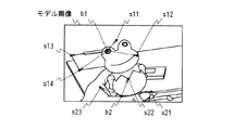
すなわち図23に示すように、モデル画像の背景が均一である場合、モデル画像の局所特徴量を検出してモデル物体上のみから特徴点が検出されることになる。従ってこの特徴点に基づいたベース点及びサポート点の設定では、図24に示すように、モデル物体上にベース点b1、b2及びサポート点s11〜s13、s21〜s23が設定されることになる。従ってこれらベース点b1、b2及びサポート点s11〜s13、s21〜s23により特徴点セットの特徴量は、正しくモデル物体の特徴量を表していることになる。 That is, as shown in FIG. 23, when the background of the model image is uniform, local feature amounts of the model image are detected, and feature points are detected only on the model object. Therefore, in setting the base points and support points based on the feature points, as shown in FIG. 24, base points b1 and b2 and support points s11 to s13 and s21 to s23 are set on the model object. Therefore, the feature quantity of the feature point set correctly represents the feature quantity of the model object by the base points b1 and b2 and the support points s11 to s13 and s21 to s23.
しかしながら図25に示すように、モデル画像に背景が含まれている場合には、この背景からも特徴点が検出されることになる。その結果、図26に示すように、背景とモデル物体とにまたがって、ベース点b1、b2及びサポート点s11〜s14、s21〜s23が設定されることになる。この場合、ベース点b1、b2及びサポート点s11〜s14、s21〜s23による特徴点セットの特徴量は、背景の特徴量をも表すことになり、その結果、認識精度が劣化することになる。 However, as shown in FIG. 25, when a background is included in the model image, feature points are also detected from this background. As a result, as shown in FIG. 26, base points b1 and b2 and support points s11 to s14 and s21 to s23 are set across the background and the model object. In this case, the feature amount of the feature point set by the base points b1 and b2 and the support points s11 to s14 and s21 to s23 also represents the background feature amount, and as a result, the recognition accuracy deteriorates.
そこでこの実施の形態では、背景とモデル物体とにまたがってベース点及びサポート点を設定しないようにし、認識精度の劣化を防止する。 In this embodiment, therefore, the base point and the support point are not set across the background and the model object, thereby preventing the recognition accuracy from deteriorating.
すなわちこの物体認識装置1においては(図2)、ユーザーにより選択された自然画によるモデル画像がモデル画像処理部2に入力される。モデル画像処理部2では(図2)、多重解像度部12において、このモデル画像により、画サイズを順次段階的に拡大、縮小したピラミット構造によるモデル画像が生成される。またセグメンテーション部13において、各解像度のモデル画像に対して、セグメンテーションの処理が実行され、これにより各解像度のモデル画像がセグメント化される。
That is, in the object recognition apparatus 1 (FIG. 2), a model image based on a natural image selected by the user is input to the model
この物体認識装置1では、続く特徴点抽出部14において、セグメント毎に、特徴点が設定されて各特徴点の特徴量が検出され、また続く特徴点セット決定部15において、セグメント毎に、各特徴点がベース点及びサポート点に設定される(図11)。これによりこの実施の形態では、セグメント毎に、同一のセグメントにベース点及びサポート点を設定して特徴点セットを設定する。
In this
ここでモデル画像をセグメンテーション化した場合、背景とモデル物体とが同一のセグメントにセグメンテーション化される場合は皆無であると言える。また仮に背景と、モデル物体とが同一のセグメントにセグメンテーション化される場合であっても、それはモデル物体の極一部のみであると言える。 Here, when the model image is segmented, it can be said that there is no case where the background and the model object are segmented into the same segment. Even if the background and the model object are segmented into the same segment, it can be said that it is only a very small part of the model object.
これによりこの実施の形態では、セグメント毎に特徴点セットを設定することにより、背景とモデル物体とにまたがってベース点及びサポート点を設定しないようにすることができ、認識精度の劣化を防止することができる。 As a result, in this embodiment, by setting the feature point set for each segment, it is possible to prevent the base point and the support point from being set across the background and the model object, thereby preventing the recognition accuracy from deteriorating. be able to.
特にこの実施の形態では、セグメンテーション部13におけるセグメンテーションの処理が、カラーセグメンテーションであり、カラーセグメンテーションの場合には、簡易な処理により、背景とモデル物体とを同一のセグメントにセグメンテーション化する状況を確実に低減することができる。従って、確実に、背景とモデル物体とにまたがってベース点及びサポート点を設定しないようにすることができ、認識精度の劣化を防止することができる。
In particular, in this embodiment, the segmentation process in the
より具体的に、特徴点抽出部14において、モデル画像は、セグメント境界上に特徴点Pが設定され、この特徴点Pの局所特徴量が検出される(図3)。この特徴点Pの設定においては、一定のピッチにより、又はランダムに、セグメント面積及び又はセグメントの周囲長が小さくなるに従って特徴点数が低下するように設定される。これによりこの実施の形態ではセグメント面積及び又はセグメントの周囲長が小さくなるに従って特徴点セットの数が低下するように設定される。ここでセグメント面積が小さい場合、セグメントの周囲長が小さい場合には、特徴点セット数を増大させても、認識精度の向上には十分に寄与し得ず、その反面、演算処理が複雑になる。これによりこの実施の形態では、セグメント面積及び又はセグメントの周囲長が小さくなるに従って特徴点セット数が低下するように設定することにより、精度の劣化を防止しつつ、処理を簡略化することができる。
More specifically, the feature
また各特徴点に対して、セグメントの内側に変位した位置に、特徴量記述中心Oが設定され(図3)、この記述中心Oの中心とした所定範囲が特徴点の局所領域に設定される。これによりこの実施の形態では、背景側の情報を含まないように局所特徴点量を記述することができ、これによっても背景による精度の低下を有効に回避することができる。 For each feature point, a feature amount description center O is set at a position displaced inside the segment (FIG. 3), and a predetermined range centered on the description center O is set as a local region of the feature point. . As a result, in this embodiment, the local feature point amount can be described so as not to include information on the background side, and this can effectively avoid a decrease in accuracy due to the background.
ここでこの特徴点及び記述中心の設定にあっては、何れを先に実行してもよく、記述中心を先に設定する場合には、各セグメントをシュリンクして記述中心設定用の領域が設定される(図4)。このとき、この実施の形態では、セグメントを細線化し、この細線化した領域をシュリンクした領域と重ね合わせて記述中心設定用の領域が設定される(図5及び図6)。またこの記述中心設定用の領域の外周に記述中心を設定した後、各記述中心から特徴点が設定される。これによりこの実施の形態では、シュリンクにより削り取られてしまう幅狭の部位についても特徴点を設定して特徴点の偏りを防止し、特徴点の偏りによる精度の劣化を防止することができる。 In this case, either the feature point or the description center can be set first. When the description center is set first, each segment is shrunk to set an area for setting the description center. (FIG. 4). At this time, in this embodiment, the segment is thinned, and the thinned region is overlapped with the shrinked region to set a description center setting region (FIGS. 5 and 6). Further, after setting the description center on the outer periphery of the region for setting the description center, feature points are set from each description center. As a result, in this embodiment, feature points can be set even for narrow portions that are scraped off by shrinking to prevent biasing of feature points, and accuracy deterioration due to biasing of feature points can be prevented.
この実施の形態では、このようにして各セグメントに設定された特徴点がベース点及びベース点をサポートするサポート点に設定されて、モデル画像に特徴点セットが設定される(図11)。この処理において、この実施の形態では、セグメント面積及び又はセグメント周囲長が低下するに従って、1つの特徴点セットを構成するサポート点の数が低下するように設定される。これによってもこの実施の形態では、精度の劣化を防止しつつ、処理を簡略化することができる。 In this embodiment, feature points set in each segment in this way are set as base points and support points that support the base points, and a feature point set is set in the model image (FIG. 11). In this processing, in this embodiment, the number of support points that constitute one feature point set is set to decrease as the segment area and / or the segment perimeter decreases. This also makes it possible to simplify processing while preventing deterioration in accuracy in this embodiment.
モデル画像は、ベース点及びサポート点の幾何学的位置関係と、ベース点及びサポート点の特徴量とにより各特徴点セットの特徴量が記述され(図12)、この特徴点セットの特徴量がマッチング部4(図18)に入力される。 In the model image, the feature amount of each feature point set is described by the geometric positional relationship between the base point and the support point and the feature amount of the base point and the support point (FIG. 12). The data is input to the matching unit 4 (FIG. 18).
これに対してクエリ画像は(図13)、多重解像度部22において、モデル画像と同様に、画サイズを順次段階的に拡大、縮小したピラミット構造によるクエリ画像が生成される。またエッジ抽出部23において、エッジ検出の処理が実行され、(図14〜図16)密に特徴点が設定されて特徴量が検出される。より具体的に、クエリ画像は、全画素が特徴点に設定され、又は所定画素ピッチ毎に、特徴点Qが設定され(図17)、エッジ情報等により各特徴点の特徴量が検出される。
On the other hand, the query image (FIG. 13) is generated in the
クエリ画像は、マッチング部4において、この特徴点から、モデル画像に設定された特徴点セットのベース点及びサポート点に対応する特徴点が検出されてマッチング処理される(図18)。
In the query image, the
すなわちクエリ画像は、モデル画像の特徴点セット毎に、各特徴点が順次処理対象に設定され、特徴点セットのサポート点に対応する部位にそれぞれ探索領域が設定される(図19)。また各探索領域において、対応するサポート点に最も類似する特徴点が検出される。クエリ画像は、この処理対象の特徴点及びサポート点に最も類似する特徴点と、特徴点セットとの間で、角度及び距離をペナルティコストとして特徴量を基準にした距離が求められ、特徴点セットに対する当該特徴点の類似度が求められる。 That is, in the query image, each feature point is sequentially set as a processing target for each feature point set of the model image, and a search area is set in each part corresponding to the support point of the feature point set (FIG. 19). In each search area, the feature point most similar to the corresponding support point is detected. In the query image, the distance based on the feature amount is obtained using the angle and the distance as a penalty cost between the feature point most similar to the feature point and the support point to be processed and the feature point set, and the feature point set is obtained. The similarity of the feature point to is obtained.
クエリ画像は、モデル画像の1つの特徴点セットに対して、全ての特徴点でこの特徴点の類似度が求められ、求めた類似度の中で最も高い類似度の特徴点が、当該特徴点セットのマッチングペアに設定される。またこの特徴点セットのマッチングペアが全ての特徴点セットについて求められる。 In the query image, the similarity of this feature point is obtained for all feature points with respect to one feature point set of the model image, and the feature point having the highest similarity among the obtained similarity points is the feature point. Set to a matching pair of sets. In addition, matching pairs of the feature point sets are obtained for all feature point sets.
しかしながらこのようにして求められるマッチングペアは、当然に、ミスマッチのペアが含まれることになる。そこでこの実施の形態では、アウトライヤ除去部26において、各特徴点セット間の幾何学的な関係を利用してミスマッチのペアがマッチングペアから除去される(図20)。またこの最終的なマッチングペア数が判定部5により判定され、モデル物体の有無が判定される。
However, the matching pair obtained in this way naturally includes a mismatched pair. Therefore, in this embodiment, the
しかしながらこのようにしてアウトライヤを除去した場合でも、背景に設定された特徴点セットとの間でマッチングペアが構成されている場合等も予測される。そこでこの実施の形態では、アウトライヤ除去部26の処理結果が一次判定部31で一次判定され(図21)、一定数以上のマッチングペアが検出された特定解像度によるモデル画像及びクエリ画像の組み合わせが検出される。またこの特定解像度によるモデル画像及びクエリ画像の組み合わせについて、モデル画像再処理部32において、モデル画像側に密に特徴点が設定されて特徴量が検出され(図22)、クエリ画像再処理部33において、クエリ画像側に特徴点セットが設定される。またバックマッチング処理部34におけるこれら特徴点及び特徴点セットによるバックマッチング処理により、改めてマッチングペアが検出される。またチェック部35において、この改めて検出されたマッチングペアが、一次判定に供した対応するマッチングペアに対応するものか否か判定され、この判定結果が二次判定部により判定されて最終的な判定結果が求められる。
However, even when the outlier is removed in this way, a case where a matching pair is configured with the feature point set set as the background is also predicted. Therefore, in this embodiment, the processing result of the
このバックマッチング処理に係る一連の処理により、この物体認識装置1では、背景によるマッチングペアを判定対象から除外することができ、これによっても背景による認識精度の低下を防止することができる。
By this series of processes related to the back matching process, the
〔実施の形態の効果〕
以上の構成によれば、モデル画像をセグメント化した後、ベース点及び対応するサポート点を同一のセグメントに設定することにより、モデル画像に背景が写っている場合でも、精度の劣化を防止することができる。
[Effect of the embodiment]
According to the above configuration, after the model image is segmented, the base point and the corresponding support point are set to the same segment, thereby preventing deterioration of accuracy even when the background is reflected in the model image. Can do.
またセグメントの境界に、ベース点及びサポート点を設定して特徴点セットを設定することにより、モデルより具体的にベース点及び対応するサポート点を同一のセグメントに設定することができ、モデル画像に背景が写っている場合でも、精度の劣化を防止することができる。 In addition, by setting a base point and a support point at the segment boundary and setting a feature point set, the base point and the corresponding support point can be set in the same segment more specifically than the model, and the model image Even when the background is reflected, it is possible to prevent deterioration in accuracy.
またセグメント面積及び又はセグメント周囲長に基づいて、1つのセグメントを構成する特徴点セットの数を設定することにより、精度の劣化を防止しつつ、処理を簡略化することができる。 In addition, by setting the number of feature point sets constituting one segment based on the segment area and / or the segment perimeter, the processing can be simplified while preventing deterioration of accuracy.
またセグメント面積及び又はセグメント周囲長に基づいて、1つの特徴点セットを構成するサポート点の数を設定することにより、精度の劣化を防止しつつ、処理を簡略化することができる。 Further, by setting the number of support points constituting one feature point set based on the segment area and / or the segment perimeter, the processing can be simplified while preventing the deterioration of accuracy.
またセグメント境界にベース点を設定すると共に、このベース点からセグメントの内側に変位した位置に、ベース点の特徴量記述中心を設定することにより、背景の影響を低減して特徴量を検出することができ、背景による精度の劣化を防止することができる。 In addition, by setting the base point at the segment boundary and setting the feature description center of the base point at the position displaced from the base point to the inside of the segment, it is possible to detect the feature quantity by reducing the influence of the background And accuracy deterioration due to background can be prevented.
またセグメントをシュリンクした領域とセグメントを細線化した領域とを重ね合わせて特徴量記述中心を設定する領域を設定し、この特徴量記述中心を設定する領域の外周に特徴量記述中心を設定することにより、特徴点の偏りを防止して精度を向上することができる。 In addition, the area where the feature description center is set is set by superimposing the area where the segment is shrunk and the area where the segment is thinned, and the feature description center is set around the area where the feature description center is set Therefore, it is possible to improve the accuracy by preventing the deviation of the feature points.
またクエリ画像については、全画素により、又は所定画素ピッチにより、密に特徴点を設定して特徴量を検出することにより、特徴点セットとの対比によるマッチング処理に適用して、背景等を有するクエリ画像から確実にモデル物体を検出することができる。 The query image is applied to matching processing by contrasting with a feature point set by densely setting feature points with all pixels or with a predetermined pixel pitch, and having a background or the like. The model object can be reliably detected from the query image.
またマッチング処理の処理結果を一次判定した後、この判定結果に基づいて処理対象画像に特徴点セットを設定すると共に、モデル画像に密に特徴点を設定し、バックマッチング処理を実行して二次判定することにより、一段と認識精度を向上することができる。 In addition, after the primary determination of the processing result of the matching process, a feature point set is set for the processing target image based on the determination result, the feature points are densely set for the model image, the back matching process is executed, and the secondary matching process is performed. By determining, the recognition accuracy can be further improved.
<第2の実施の形態>
この実施の形態では、上述の実施の形態の物体認識装置1におけるモデル画像及びクエリ画像の処理を入れ換える。すなわちこの実施の形態では、クエリ画像をセグメント化して特徴点セットを設定し、またモデル画像に密に特徴点を設定する。またこれら特徴点セット及び特徴点をマッチング処理して処理結果を一次判定する。またこの一次判定結果に基づいてモデル画像に特徴点セットを設定すると共に、クエリ画像に密に特徴点を設定し、バックマッチング処理、二次判定の処理を実行する。
<Second Embodiment>
In this embodiment, the processing of the model image and the query image in the
この実施の形態のように、モデル画像及びクエリ画像の処理を入れ換えるようにしても、上述の実施の形態と同様の効果を得ることができる。 Even if the processing of the model image and the query image is interchanged as in this embodiment, the same effect as in the above-described embodiment can be obtained.
<第3の実施の形態>
この実施の形態では、上述の第1の実施の形態の物体認識装置におけるクエリ画像の処理、又は第2の実施の形態の物体認識装置におけるモデル画像の処理において、セグメンテーションの処理を実行し、エッジ境界に代えて、セグメント境界により特徴点の特徴量を検出する。また特徴点を密に設定し、セグメント境界の特徴点のみ、選択的にマッチング処理対象に設定する。
<Third Embodiment>
In this embodiment, in the query image processing in the object recognition device of the first embodiment described above or the model image processing in the object recognition device of the second embodiment, segmentation processing is executed, and edge processing is performed. Instead of the boundary, the feature amount of the feature point is detected by the segment boundary. Also, feature points are set densely, and only feature points at the segment boundary are selectively set as matching processing targets.
この実施の形態のように、クエリ画像の処理、又はモデル画像の処理にもセグメンテーションの処理を適用するようにしても、上述の実施の形態と同様の効果を得ることができる。 Even if the segmentation process is applied to the query image process or the model image process as in this embodiment, the same effects as those of the above-described embodiment can be obtained.
<第4の実施の形態>
図27は、本発明の第4の実施の形態に係るディジタルカメラを示すブロック図である。このディジタルカメラ41において、撮像部42は、撮像素子、この撮像素子の受光面に光学像を形成する光学系等により構成され、コントローラ43の制御により撮像結果を取得して出力する。信号処理部48は、コントローラ43の制御により撮像部42から出力される撮像結果を信号処理して画像データを生成し、この画像データをバスBUSに出力する。圧縮伸長部44は、コントローラ43の制御によりバスBUSに出力される画像データをデータ圧縮して符号化データを出力し、またこれとは逆にバスBUSに出力される符号化データをデータ伸長して画像データを出力する。
<Fourth embodiment>
FIG. 27 is a block diagram showing a digital camera according to the fourth embodiment of the present invention. In the
記録部45は、コントローラ43の制御により、バスBUSに出力される符号化データを記録して保持し、また保持した符号化データを再生してバスBUSに出力する。表示部46は、コントローラ43の制御によりバスBUSに出力される画像データ、各種メニュー画面等を表示する。操作部47は、このディジタルカメラ41に設けられた操作子、表示部46の表示画面に設けられたタッチパネル等により構成され、ユーザーの操作をコントローラ43に通知する。
The
コントローラ43は、このディジタルカメラ41の動作を制御する制御手段であり、図示しないメモリに記録されたプログラムの実行により各部の動作を制御する。この制御によりコントローラ43は、ユーザーがシャッターボタンを操作して撮像結果の取得を指示すると、撮像部42、信号処理部48、表示部46の制御により撮像結果を取得して表示部46で表示する。またこの撮像結果の記録をユーザーが指示すると、圧縮伸長部44の制御によりこの表示部46で表示した画像データをデータ圧縮して符号化データを生成し、この符号化データを記録部45で記録する。
The
これに対してユーザーがメニュー画面の表示を指示すると、表示部46の制御によりメニュー画面を表示する。またこのメニュー画面におけるメニューの選択により、ユーザーが記録部45に記録した撮像結果の表示を指示すると、記録部45に記録された符号化データを順次再生して圧縮伸長部44でデータ伸長し、その結果得られる画像データを表示部46で表示する。
On the other hand, when the user instructs display of the menu screen, the menu screen is displayed under the control of the
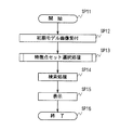
これに対してユーザーが撮像結果の検索を指示すると、図28の処理手順を実行し、記録部45に記録された撮像結果から、ユーザーの指示したモデル物体の撮像結果を検索する。
On the other hand, when the user instructs to search for the imaging result, the processing procedure of FIG. 28 is executed, and the imaging result of the model object instructed by the user is searched from the imaging result recorded in the
すなわちコントローラ43は、この処理手順を開始すると、ステップSP11からステップSP12に移る。ここでコントローラ43は、モデル画像の選択を受け付ける。以下、このステップSP12で受け付けたモデル画像を初期モデル画像と呼ぶ。具体的に、コントローラ43は、記録部45に記録された撮像結果を順次読み出して圧縮伸長部44でデータ伸長し、表示部46に撮像結果を一覧表示する。またこの一覧表示におけるタッチパネルの操作により、検索対象の画像の選択を受け付け、図29に示すように、表示部46の一覧表示を検索対象の画像の表示に切り換える。またこの表示部46の表示におけるタッチパネルの操作により、モデル物体MOが撮影されている領域ARの設定を受け付ける。コントローラ43は、この領域ARの画像データを選択的に図示しないメモリに記録することにより、この領域ARの画像を切り出して初期モデル画像に設定する。コントローラ43は、領域ARの画像を切り出して初期モデル画像に設定することにより、例えば背景、モデル物体と共に撮影された他の物体等による検出精度の劣化を防止する。
That is, when starting this processing procedure, the
続いてコントローラ43は、ステップSP13に移り、特徴点セット選択処理を実行する。ここで特徴点セット選択処理は、モデル物体MOの検出に有意な特徴点セットを選択する処理であり、詳細は後述する。
Subsequently, the
続いてコントローラ43は、ステップSP14に移り、記録部45に記録された撮像結果を順次処理対象に設定し、初期モデル画像との間でマッチング処理を実行し、モデル物体MOを撮影した撮像結果を検出する。この処理において、コントローラ43は、モデル画像処理部2又は判定部5における特徴点セットの設定に代えて(図1、図2参照)、このステップSP13で選択した特徴点セットを初期モデル画像又はクエリ画像に設定し、第1、第2又は第3の実施の形態について上述した手法によりマッチング処理を実行する。
Subsequently, the
コントローラ43は、記録部45に記録された撮像結果の全てについて、マッチング処理を完了すると、ステップSP15に移り、モデル物体MOを検出した撮像結果を表示部46で一覧表示した後、ステップSP16に移ってこの処理手順を終了する。
When the
〔特徴点セット選択処理〕
図30は、図28の特徴点セット選択処理(ステップSP13)を詳細に示すフローチャートである。コントローラ43は、この処理手順を開始すると、ステップSP21からステップSP22に移ってクロップモデル画像作成処理を実行し、記録部45に記録された撮像結果からクロップモデル画像を作成する。
[Feature point set selection processing]
FIG. 30 is a flowchart showing in detail the feature point set selection process (step SP13) of FIG. When starting this processing procedure, the
ここでクロップモデル画像は、記録部45に記録された撮像結果から作成される初期モデル画像に対応する画像である。コントローラ43は、記録部45に記録された撮像結果を順次選択し、初期モデル画像との間で第1〜第3の実施の形態について上述したマッチング処理を実行する。コントローラ43は、このマッチング処理により、図31に示すように、モデル物体MOが撮影されていると判断される画像を所定枚数検出してクエリ画像に設定する。ここでクエリ画像は、クロップモデル画像の作成元の画像である。コントローラ43は、このクエリ画像を設定する際のマッチング処理で検出されるマッチングペアを記録して保持する。
Here, the crop model image is an image corresponding to the initial model image created from the imaging result recorded in the
コントローラ43は、記録して保持したマッチングペアをそれぞれ構成するベース点の座標から、クエリ画像上のベース点の座標を初期モデル画像上の対応するベース点の座標に座標変換するアフィン変換のパラメータ(図31ではアフィンパラメータにより示す)を検出する。またこの検出したアフィン変換のパラメータを用いてそれぞれ対応するクエリ画像をアフィン変換した後、初期モデル画像に対応する領域を切り出し、クロップモデル画像を作成する。ここでクロップモデル画像は、正しくアフィンパラメータが求められていれば、それぞれ初期モデル画像と同じ画サイズであり、初期モデル画像と重ね合わせると、クロップモデル画像のモデル物体MOと初期モデル画像のモデル物体MOとが概ね重なり合うことになる。このことを利用してこの実施の形態では、特徴点セットを選択してマッチング処理の信頼性を向上する。
The
続いてコントローラ43は、ステップSP23に移り、クロップモデル画像にそれぞれ特徴点セットを設定する。なおこの特徴点セットは、第1の実施の形態について上述した手法により設定される。
Subsequently, the
続いてコントローラ43は、ステップSP24に移り、重要度決定処理を実行する。ここでコントローラ43は、クロップモデル画像に設定した特徴点セットと、初期モデル画像に設定した特徴点セットとを特徴点セットのシードに設定する。またモデル物体MOの検出に対する有意性を示す重要度を各特徴点セットのシードに設定する。
Subsequently, the
続いてコントローラ43は、ステップSP25に移り、図32に示すように、図14で設定した重要度を所定のしきい値で判定し、特徴点セットのシードから重要度の高い特徴点セットを選択する。続いてコントローラ43は、ステップSP26に移って元の処理手順に戻る。従ってコントローラ43は、このステップSP25で選択した特徴点セットを用いて、ステップSP14の検索処理を実行することになる。
Subsequently, the
〔重要度決定処理〕
図33及び図34は、重要度決定処理を詳細に示すフローチャートである。コントローラ43は、この処理手順を開始すると、ステップSP31からステップSP32に移り、変数iを値0に初期化する。ここで変数iは、初期モデル画像、クロップモデル画像から特徴点セットの選択対象を特定する変数である。続いてコントローラ43は、ステップSP33に移り、変数iにより特定される初期モデル画像又はクロップモデル画像を選択する。
[Importance determination process]
33 and 34 are flowcharts showing the importance level determination process in detail. When starting this processing procedure, the
続いてコントローラ43は、ステップSP34に移り、変数mを値0に初期化する。ここで変数mは、ステップSP33で選択したモデル画像に設定された特徴点セットから、選択対象の特徴点セットを特定する変数である。コントローラ43は、続いてステップSP35に移り、ステップSP33で選択したモデル画像から変数mで特定される特徴点セットを検出する。なおコントローラ43は、このステップSP35において、併せて後述する選択対象の特徴点セットに係るカウンタのカウント値Repcnt、距離和を値0にリセットする。
Subsequently, the
続いてコントローラ43は、ステップSP36に移り、変数jを値0に初期化する。ここで変数jは、初期モデル画像、クロップモデル画像から、重要度検出のための比較対象を特定する変数である。コントローラ43は、続くステップSP37において、変数jにより特定される初期モデル画像又はクロップモデル画像を選択する。
Subsequently, the
続いてコントローラ43は、ステップSP38に移り、変数i及びjが等しいか否か判断する。ここで肯定結果が得られると、コントローラ43は、ステップSP38からステップSP39に移り、変数jを値1だけインクリメントしてステップSP37に戻る。
Subsequently, the
これに対してステップSP38で否定結果が得られると、コントローラ43は、ステップSP38からステップSP40に移る。ここでコントローラ43は、ステップSP37で選択した画像に設定された特徴点セットを比較対象の特徴点セットに設定する。
On the other hand, if a negative result is obtained in step SP38, the
コントローラ43は、続くステップSP41において、この比較対象の特徴点セットとステップSP35で選択した選択対象の特徴点セットとの間でマッチング処理を実行し、選択対象の特徴点セットに対する類似度を比較対象の特徴点セット毎に検出する。なおこのマッチング処理には、種々の手法を適用することができるものの、この実施の形態ではKNN法を適用して上述の実施の形態と同一の処理により類似度を検出する。
In subsequent step SP41, the
続いてコントローラ43は、ステップSP42に移り(図34)、ステップSP41で検出した類似度をソートし、比較対象の特徴点セットを類似度の高い側から所定個数Kだけ選択する。また選択した特徴点セットにおいて、ベース点の座標が、選択対象の特徴点セットにおけるベース点の座標と一致するものが存在するか否か判断する。なおここでこの一致の判断は、当然に、一定の誤差を見込んで判断される。
Subsequently, the
ここで肯定結果が得られると、コントローラ43は、ステップSP42からステップSP43に移り、選択対象の特徴点セットに係るカウンタのカウント値Repcntを値1だけインクリメントする。またこのときベース点の座標が一致する特徴点セットについて、ベース点間の距離を計算し、この距離を距離和に加算してステップSP44に移る。これに対してステップSP42で否定結果が得られると、コントローラ43は、直接、ステップSP42からステップSP44に移る。
If a positive result is obtained here, the
ステップSP44において、コントローラ43は、変数jが所定値T未満か否か判断することにより、未だ比較対象に設定していない初期モデル画像、クロップモデル画像が存在するか否か判断する。ここで肯定結果が得られると、コントローラ43は、ステップSP44からステップSP39に移り、変数jをインクリメントしてステップSP37に戻る。
In step SP44, the
従ってコントローラ43は、初期モデル画像、クロップモデル画像に設定された特徴点セットの1つを選択対象に設定して、ステップSP37−SP38−SP39−SP40−SP41−SP42−SP44−SP39−SP37、又はステップSP37−SP38−SP39−SP40−SP41−SP42−SP43−SP44−SP39−SP37の処理手順を繰り返すことになる。その結果、コントローラ43は、図35に示すように、比較対象の画像を順次切り換えて、選択対象の特徴点セットとマッチングする特徴点セットの個数を距離和と共に検出する。
Therefore, the
コントローラ43は、ステップSP44で否定結果が得られると、ステップSP44からステップSP45に移る。ここでコントローラ43は、変数mが所定値M未満か否か判断することにより、選択対象の初期モデル画像、クロップモデル画像に、未だ選択対象に設定していない特徴点セットが存在するか否か判断する。ここで肯定結果が得られると、コントローラ43は、ステップSP45からステップSP46に移り、変数mをインクリメントしてステップSP35に戻り、選択対象の特徴点セットを切り換える。
If a negative result is obtained in step SP44, the
これに対してステップSP45で否定結果が得られると、コントローラ43は、ステップSP45からステップSP47に移る。ここでコントローラ43は、変数iが所定値T未満か否か判断することにより、未だ選択対象に設定していない初期モデル画像、クロップモデル画像が存在するか否か判断する。ここで肯定結果が得られると、コントローラ43は、ステップSP47からステップSP48に移り、変数iをインクリメントしてステップSP33に戻り、選択対象の画像を切り換える。
On the other hand, if a negative result is obtained in step SP45, the
これに対してステップSP47で否定結果が得られると、コントローラ43は、ステップSP47からステップSP49に移る。ここでコントローラ43は、図35に示すように、選択対象の特徴点セット毎に検出されたカウント値Repcntを値の大きい順にソートする。またカウント値Repcntが等しいものについては、距離和の小さい順にソートする。
On the other hand, if a negative result is obtained in step SP47, the
ここでこのソート結果で上位の特徴点セットは、他のモデル画像に対して、よくマッチする特徴点セットだと言え、モデル物体上から抽出された特徴点セットである可能性が極めて高いと言える。このことを利用してコントローラ43は、ソート結果に順位を設定し、この実施の形態では、この順位が重要度に設定される。
Here, it can be said that the top feature point set in this sort result is a feature point set that matches well with other model images, and it is highly possible that the feature point set is extracted from the model object. . Using this fact, the
コントローラ43は、このステップSP49の処理を実行すると、ステップSP50に移り、元の処理手順に戻る。
When executing the processing of step SP49, the
この実施の形態によれば、モデル物体の検出に有意な特徴点セットを事前に選択してマチング処理を実行することにより、一段と効率、精度良くマッチング処理を実行することができる。従って処理時間を格段的に低減することができる。また背景同士のマッチングによって引き起こされる、false-positiveによる認識率の低下を防止することができる。 According to this embodiment, the matching process can be executed with higher efficiency and accuracy by selecting the feature point set significant for the detection of the model object in advance and executing the matching process. Accordingly, the processing time can be significantly reduced. In addition, it is possible to prevent the recognition rate from being lowered due to false-positive caused by matching between backgrounds.
またこの事前の処理におけるクロップ画像の作成に、上述の実施の形態の手法を適用することによっても、十分に認識精度を向上することができる。 In addition, the recognition accuracy can be sufficiently improved by applying the method of the above-described embodiment to the creation of the cropped image in the prior processing.
<第5の実施の形態>
この実施の形態のディジタルカメラは、初期モデル画像、クロップモデル画像に特徴点セットを設定する際のセグメント化の処理を有効に利用して、第4の実施の形態における重要度設定処理を簡略化する。この実施の形態のディジタルカメラは、このセグメント化の処理に関する構成が異なる点を除いて、第5の実施の形態のディジタルカメラ41と同一に構成される。従って以下においては、適宜、図27の構成を流用して説明する。
<Fifth embodiment>
The digital camera of this embodiment simplifies the importance setting process in the fourth embodiment by effectively using the segmentation process when setting the feature point set in the initial model image and the crop model image. To do. The digital camera of this embodiment is configured in the same way as the
この実施の形態において、コントローラ43は、ステップSP49(図34)におけるソーティングの際に、セグメント毎にカウント値Repcntを集計する。また集計結果を当該セグメントの特徴点セット数で割り算する。ここでこの割り算値が小さい場合、当該セグメントの特徴点セットは、例えカウント値Repcntが大きいものであっても、モデル物体MOの特徴点セットである可能性が低いと言える。そこでコントローラ43は、この割り算値が小さいセグメントの特徴点セットについては、ソート対象から除外してソーティングの処理を実行する。
In this embodiment, the
なおこの場合、結局、特徴点セット当たりのカウント値Repcntによりセグメントの信頼性を判定し、モデル物体では無いと判断されるセグメントの特徴点セットを処理対象から最後に除外することになる。しかしながらこのセグメントの信頼性を判定して処理対象から除外する処理にあっては、図33及び図34における処理手順で適宜実行して処理を簡略化してもよい。具体的には、例えば変数iにより特定されるモデル画像の特徴点セットに対して、変数jにより特定されるクエリ画像のマッチングをn枚(n<T)実行した時点で、同様にしてセグメントの信頼性を判定して以降の処理から除外するようにしてもよい。 In this case, the reliability of the segment is determined based on the count value Repcnt per feature point set, and the feature point set of the segment that is determined not to be a model object is finally excluded from the processing target. However, in the process of determining the reliability of the segment and excluding it from the processing target, the process may be simplified by appropriately executing the processing procedure in FIGS. Specifically, for example, when n (n <T) matching of the query image specified by the variable j is performed on the feature point set of the model image specified by the variable i, the segment is similarly processed. The reliability may be determined and excluded from the subsequent processing.
また逆にこの割り算値が大きい場合、当該セグメントの特徴点セットは、例えカウント値Repcntが小さいものであっても、モデル物体MOの特徴点セットである可能性が高いと言える。そこでこの割り算値が小さいセグメントの特徴点セットについては、単純にカウント値によりソーティングする場合に比して高い順位となるように、カウント値に重み付けしてソーティングの処理を実行してもよい。 On the other hand, when this division value is large, it can be said that there is a high possibility that the feature point set of the segment is a feature point set of the model object MO even if the count value Repcnt is small. Therefore, for the feature point set of the segment with a small division value, the count value may be weighted so as to be ranked higher than when sorting is simply performed based on the count value.
また特徴点セット毎のソーティングに代えて、この割り算値によりセグメント単位で特徴点セットを選択してもよい。 Further, instead of sorting for each feature point set, a feature point set may be selected on a segment basis by this division value.
この実施の形態では、セグメンテーションを有効に利用して、第4の実施の形態と同様の効果を得ることができる。 In this embodiment, the same effect as that of the fourth embodiment can be obtained by effectively using segmentation.
<変形例>
なお上述の第4の実施の形態等では、所定枚数だけクロップモデル画像を処理する場合について述べた。しかしながら本発明はこれに限らず、必要に応じて処理するクロップモデル画像の数を可変してもよい。具体的に、例えば初期モデル画像の特徴点セットをn(n<T)枚のクロップモデル画像との間でマッチング処理してカウント値がnの特徴点セットが多数検出されている場合、十分に信頼性の高い特徴点セットを検出できていると判断することができる。従ってこの場合、クロップモデル画像の枚数をn枚に変更すれば、処理を簡略化することができる。またこれとは逆に、カウント値が小さい場合には、比較対象のクロップモデル画像を増大させて、信頼性を向上することができる。
<Modification>
In the fourth embodiment and the like described above, the case where a predetermined number of crop model images are processed has been described. However, the present invention is not limited to this, and the number of crop model images to be processed may be varied as necessary. Specifically, for example, when a feature point set of an initial model image is matched with n (n <T) crop model images, and a large number of feature point sets with a count value of n are detected, it is sufficient. It can be determined that a highly reliable feature point set has been detected. Therefore, in this case, if the number of crop model images is changed to n, the processing can be simplified. On the contrary, when the count value is small, the number of crop model images to be compared can be increased to improve the reliability.
また上述の第4及び第5の実施の形態では、ユーザーによる領域の指定によりモデル物体が撮影された領域を検出する場合について述べた。しかしながら本発明はこれに限らず、例えば顔検出等の手法を適用してモデル物体が撮影された領域を検出するようにしてもよい。 In the fourth and fifth embodiments described above, the case has been described in which the region where the model object is photographed is detected by the user specifying the region. However, the present invention is not limited to this, and a region where a model object is photographed may be detected by applying a technique such as face detection.
また上述の第4及び第5の実施の形態では、本発明をディジタルカメラに適用する場合について述べた。しかしながら本発明はこれに限らず、例えばインターネット上で所望の画像を検索する場合等にも広く適用することができる。 In the fourth and fifth embodiments, the case where the present invention is applied to a digital camera has been described. However, the present invention is not limited to this, and can be widely applied to, for example, searching for a desired image on the Internet.
また上述の実施の形態においては、ソフトウエア構成により物体認識装置を構成する場合について述べたが、本発明はこれに限らず、ハードウエア構成により物体認識装置を構成する場合にも広く適用することができる。 In the above-described embodiment, the case where the object recognition device is configured by the software configuration has been described. However, the present invention is not limited to this, and the present invention can be widely applied to the case where the object recognition device is configured by the hardware configuration. Can do.
また上述の実施の形態においては、複数の静止画像による自然画からモデル画像によるモデル物体を検出する場合について述べたが、本発明はこれに限らず、動画像からモデル物体を検出する場合、撮像結果から所望の被写体を検出する場合等に広く適用することができる。 In the above-described embodiment, the case of detecting a model object by a model image from a natural image by a plurality of still images has been described. However, the present invention is not limited to this, and imaging is performed when a model object is detected from a moving image. The present invention can be widely applied when a desired subject is detected from the result.
また上述の実施の形態では、それぞれ好適な構成を説明したが、本発明はこれらの構成に限らず、必要に応じて上述の構成を組み合わせてもよい。 In the above-described embodiments, suitable configurations have been described. However, the present invention is not limited to these configurations, and the above-described configurations may be combined as necessary.
本発明は、例えばデータベースに記録した多数の静止画像から特定の被写体を撮影した静止画像を検索する場合に適用することができる。 The present invention can be applied, for example, to search for a still image obtained by photographing a specific subject from a large number of still images recorded in a database.
1……物体認識装置、2……モデル画像処理部、3……クエリ画像処理部、4……マッチング部、5……判定部、13……セグメンテーション部、14……特徴点抽出部、15……特徴点セット決定部、16、24……特徴量記述部、23……エッジ抽出部、25……マッチング処理部、26……アウトライヤ除去部、31……一次判定部、32……モデル画像再処理部、33……クエリ画像再処理部、34……バックマッチング処理部、35……チェック部、36……二次判定部
DESCRIPTION OF
Claims (16)
処理対象画像を処理する処理対象画像処理部と、
前記モデル画像処理部及び処理対象画像処理部の処理結果をマッチング処理するマッチング部と、
前記マッチング部の処理結果を判定して、前記処理対象画像中のモデル物体の有無を判定する判定部とを有し、
前記モデル画像処理部は、
前記モデル画像に、ベース点と前記ベース点をサポートするサポート点とによる特徴点セットを設定し、前記ベース点および前記サポート点の局所領域の特徴量を検出して前記特徴点セットの特徴量を検出する特徴点セット決定部を有し、
前記処理対象画像処理部は、
前記処理対象画像の全画素を特徴点に設定し、又は前記処理対象画像に所定画素ピッチで前記特徴点を設定し、前記特徴点に局所領域を設定して特徴量を検出する特徴点設定部を有し、
前記マッチング部は、
前記モデル画像に設定された前記特徴点セットの特徴量と、前記処理対象画像に設定された前記特徴点の特徴量とを比較し、前記モデル画像に設定された前記特徴点セットのベース点及びサポート点に対応する前記特徴点を検出することにより、前記特徴点セットに対応する前記特徴点を検出し、前記マッチング処理を実行し、
前記モデル画像処理部は、
前記モデル画像をセグメント化するセグメンテーション部を有し、
前記特徴点セット決定部は、
前記モデル画像のセグメント毎に、前記セグメントの境界上の複数の特徴点のうちの1の特徴点を前記ベース点、他の特徴点を前記ベース点に対応する前記サポート点として同一のセグメントに設定して前記特徴点セットを設定する
物体認識装置。 A model image processing unit for processing model images;
A processing target image processing unit that processes the processing target image;
A matching unit for matching the processing results of the model image processing unit and the processing target image processing unit;
A determination unit that determines the processing result of the matching unit and determines the presence or absence of a model object in the processing target image;
The model image processing unit
A feature point set based on a base point and a support point that supports the base point is set in the model image, and a feature amount of a local region of the base point and the support point is detected to obtain a feature amount of the feature point set. A feature point set determining unit to detect,
The processing target image processing unit
A feature point setting unit that sets all the pixels of the processing target image as feature points, or sets the feature points at a predetermined pixel pitch in the processing target image, sets a local region to the feature points, and detects a feature amount Have
The matching unit is
The feature amount of the feature point set set in the model image is compared with the feature amount of the feature point set in the processing target image, and a base point of the feature point set set in the model image and By detecting the feature point corresponding to the support point, the feature point corresponding to the feature point set is detected, and the matching process is executed.
The model image processing unit
A segmentation unit for segmenting the model image;
The feature point set determination unit
For each segment of the model image, one feature point among a plurality of feature points on the boundary of the segment is set as the base point, and the other feature point is set as the support point corresponding to the base point in the same segment. And setting the feature point set.
処理対象画像を処理する処理対象画像処理部と、
前記モデル画像処理部及び処理対象画像処理部の処理結果をマッチング処理するマッチング部と、
前記マッチング部の処理結果を判定して、前記処理対象画像中のモデル物体の有無を判定する判定部とを有し、
前記処理対象画像処理部は、
前記処理対象画像に、ベース点と前記ベース点をサポートするサポート点とによる特徴点セットを設定し、前記ベース点および前記サポート点の局所領域の特徴量を検出して前記特徴点セットの特徴量を検出する特徴点セット決定部を有し、
前記モデル画像処理部は、
前記モデル画像の全画素を特徴点に設定し、又は前記モデル画像に所定画素ピッチで前記特徴点を設定し、前記特徴点に局所領域を設定して特徴量を検出する特徴点設定部を有し、
前記マッチング部は、
前記処理対象画像に設定された前記特徴点セットの特徴量と、前記モデル画像に設定された前記特徴点の特徴量とを比較し、前記処理対象画像に設定された前記特徴点セットのベース点及びサポート点に対応する前記特徴点を検出することにより、前記特徴点セットに対応する前記特徴点を検出し、前記マッチング処理を実行し、
前記処理対象画像処理部は、
前記処理対象画像をセグメント化するセグメンテーション部を有し、
前記特徴点セット決定部は、
前記処理対象画像のセグメント毎に、前記セグメントの境界上の複数の特徴点のうちの1の特徴点を前記ベース点、他の特徴点を前記ベース点に対応する前記サポート点として同一のセグメントに設定して前記特徴点セットを設定する
物体認識装置。 A model image processing unit for processing model images;
A processing target image processing unit that processes the processing target image;
A matching unit for matching the processing results of the model image processing unit and the processing target image processing unit;
A determination unit that determines the processing result of the matching unit and determines the presence or absence of a model object in the processing target image;
The processing target image processing unit
A feature point set including a base point and a support point that supports the base point is set in the processing target image, and a feature amount of a local region of the base point and the support point is detected to detect a feature amount of the feature point set. A feature point set determination unit for detecting
The model image processing unit
A feature point setting unit configured to set all the pixels of the model image as feature points, or to set the feature points at a predetermined pixel pitch in the model image, and to set a local region to the feature points to detect a feature amount; And
The matching unit is
The feature amount of the feature point set set in the processing target image is compared with the feature amount of the feature point set in the model image, and the base point of the feature point set set in the processing target image And detecting the feature point corresponding to the support point to detect the feature point corresponding to the feature point set, and executing the matching process,
The processing target image processing unit
A segmentation unit for segmenting the processing target image;
The feature point set determination unit
For each segment of the image to be processed , one feature point of the plurality of feature points on the boundary of the segment is set as the base point, and the other feature point is set as the support point corresponding to the base point. An object recognition device configured to set the feature point set.
処理対象画像を処理する処理対象画像処理ステップと、
前記モデル画像処理ステップ及び処理対象画像処理ステップの処理結果をマッチング処理するマッチングステップと、
前記マッチングステップの処理結果を判定して、前記処理対象画像中のモデル物体の有無を判定する判定ステップとを有し、
前記モデル画像処理ステップは、
前記モデル画像に、ベース点と前記ベース点をサポートするサポート点とによる特徴点セットを設定し、前記ベース点および前記サポート点の局所領域の特徴量を検出して前記特徴点セットの特徴量を検出する特徴点セット決定ステップを有し、
前記処理対象画像処理ステップは、
前記処理対象画像の全画素を特徴点に設定し、又は前記処理対象画像に所定画素ピッチで前記特徴点を設定し、前記特徴点に局所領域を設定して特徴量を検出する特徴点設定ステップを有し、
前記マッチングステップは、
前記モデル画像に設定された前記特徴点セットの特徴量と、前記処理対象画像に設定された前記特徴点の特徴量とを比較し、前記モデル画像に設定された前記特徴点セットのベース点及びサポート点に対応する前記特徴点を検出することにより、前記特徴点セットに対応する前記特徴点を検出し、前記マッチング処理を実行し、
前記モデル画像処理ステップは、
前記モデル画像をセグメント化するセグメンテーションステップを有し、
前記特徴点セット決定ステップは、
前記モデル画像のセグメント毎に、前記セグメントの境界上の複数の特徴点のうちの1の特徴点を前記ベース点、他の特徴点を前記ベース点に対応する前記サポート点として同一のセグメントに設定して前記特徴点セットを設定する
物体認識方法。 A model image processing step for processing the model image;
A processing target image processing step for processing the processing target image;
A matching step for matching the processing results of the model image processing step and the processing target image processing step;
Determining a processing result of the matching step, and determining a presence or absence of a model object in the processing target image,
The model image processing step includes
A feature point set based on a base point and a support point that supports the base point is set in the model image, and a feature amount of a local region of the base point and the support point is detected to obtain a feature amount of the feature point set. A feature point set determining step to detect,
The processing target image processing step includes
A feature point setting step of setting all the pixels of the processing target image as feature points, or setting the feature points at a predetermined pixel pitch in the processing target image, and setting a local region to the feature points to detect a feature amount Have
The matching step includes
The feature amount of the feature point set set in the model image is compared with the feature amount of the feature point set in the processing target image, and a base point of the feature point set set in the model image and By detecting the feature point corresponding to the support point, the feature point corresponding to the feature point set is detected, and the matching process is executed.
The model image processing step includes
A segmentation step for segmenting the model image;
The feature point set determination step includes:
For each segment of the model image, one feature point among a plurality of feature points on the boundary of the segment is set as the base point, and the other feature point is set as the support point corresponding to the base point in the same segment. An object recognition method that sets the feature point set.
セグメント面積及び又はセグメント周囲長に基づいて、1つのセグメントに設定する前記特徴点セットの数を設定し、
セグメント面積及び又はセグメント周囲長に基づいて、1つの特徴点セットを構成する前記サポート点の数を設定する
請求項3に記載の物体認識方法。 The feature point set determination step includes:
Based on the segment area and / or the segment perimeter, set the number of feature point sets to be set in one segment,
The object recognition method according to claim 3, wherein the number of support points constituting one feature point set is set based on a segment area and / or a segment perimeter.
前記セグメントの境界に、前記ベース点及び又はサポート点を設定すると共に、前記ベース点及び又はサポート点から前記セグメントの内側に変位した位置に、前記ベース点及び又はサポート点の特徴量記述中心を設定する記述中心設定ステップを有し、
前記特徴量記述中心を中心にして前記ベース点及び又はサポート点の局所領域を設定し、
前記局所領域の特徴量により前記ベース点及び又はサポート点の特徴量を検出して前記特徴点セットの特徴量を設定する
請求項3に記載の物体認識方法。 The feature point set determination step includes:
The base point and / or support point is set at the boundary of the segment, and the feature description center of the base point and / or support point is set at a position displaced from the base point and / or support point to the inside of the segment. A description center setting step,
A local region of the base point and / or support point is set around the feature description center,
The object recognition method according to claim 3, wherein the feature amount of the feature point set is set by detecting the feature amount of the base point and / or the support point based on the feature amount of the local region.
処理対象のセグメントを前記局所領域に応じた大きさによりシュリンクするシュリンクのステップと、
前記処理対象のセグメントを細線化する細線化のステップと、
前記シュリンクのステップにより生成された領域と、前記細線化のステップにより細線化された領域とを重ね合わせて、前記特徴量記述中心を設定する領域を設定する記述中心の領域設定のステップとを有し、
前記特徴量記述中心を設定する領域の外周に前記特徴量記述中心を設定し、
前記特徴点セット決定ステップは、
前記特徴量記述中心に基づいて、対応する前記ベース点及び又はサポート点を設定する
請求項5に記載の物体認識方法。 The description center setting step includes:
A shrinking step of shrinking a segment to be processed with a size corresponding to the local region;
A thinning step of thinning the segment to be processed;
A description center region setting step for setting a region for setting the feature amount description center by superimposing the region generated by the shrink step and the region thinned by the thinning step; And
Setting the feature description center on the outer periphery of the region for setting the feature description center;
The feature point set determination step includes:
Based on the feature description center, the corresponding base point and / or support point is set.
The object recognition method according to claim 5 .
前記処理対象画像のエッジ上の特徴点を選択して、前記マッチングステップの処理対象の特徴点に設定する
請求項3に記載の物体認識方法。 The feature point setting step includes:
Select a feature point on the edge of the processing target image and set it as the processing target feature point of the matching step
The object recognition method according to claim 3 .
前記マッチングステップの処理結果を判定して、前記処理対象画像中のモデル物体の有無を一次判定する一次判定ステップと、
前記一次判定ステップの判定結果に応じて、前記モデル画像の全画素を特徴点に設定し、又は前記モデル画像に所定画素ピッチで特徴点を設定し、前記モデル画像の特徴点の特徴量を検出するモデル画像再処理ステップと、
前記一次判定ステップの判定結果に応じて、前記処理対象画像に前記特徴点セットを設定する処理対象画像再処理ステップと、
前記処理対象画像再処理ステップにより前記処理対象画像に設定された前記特徴点セットの特徴量と、前記モデル画像再処理ステップにより前記モデル画像に設定された前記特徴点の特徴量との比較により、バックマッチング処理を実行するバックマッチングステップと、
前記バックマッチングステップの処理結果を判定して、前記処理対象画像中のモデル物体の有無を二次判定する二次判定ステップとを有する
請求項3に記載の物体認識方法。 The determination step includes
A primary determination step of determining a processing result of the matching step to primarily determine the presence or absence of a model object in the processing target image;
Depending on the determination result of the primary determination step, all the pixels of the model image are set as feature points, or feature points are set in the model image at a predetermined pixel pitch, and feature quantities of the feature points of the model image are detected. A model image reprocessing step,
A processing target image reprocessing step of setting the feature point set in the processing target image according to a determination result of the primary determination step;
By comparing the feature amount of the feature point set set to the processing target image by the processing target image reprocessing step and the feature amount of the feature point set to the model image by the model image reprocessing step, A back matching step for performing back matching processing;
A secondary determination step of determining a processing result of the back matching step and secondarily determining whether or not there is a model object in the processing target image.
The object recognition method according to claim 3 .
処理対象画像を処理する処理対象画像処理ステップと、
前記モデル画像処理ステップ及び処理対象画像処理ステップの処理結果をマッチング処理するマッチングステップと、
前記マッチングステップの処理結果を判定して、前記処理対象画像中のモデル物体の有無を判定する判定ステップとを有し、
前記処理対象画像処理ステップは、
前記処理対象画像に、ベース点と前記ベース点をサポートするサポート点とによる特徴点セットを設定し、前記ベース点および前記サポート点の局所領域の特徴量を検出して前記特徴点セットの特徴量を検出する特徴点セット決定ステップを有し、
前記モデル画像処理ステップは、
前記モデル画像の全画素を特徴点に設定し、又は前記モデル画像に所定画素ピッチで前記特徴点を設定し、前記特徴点に局所領域を設定して特徴量を検出する特徴点設定ステップを有し、
前記マッチングステップは、
前記処理対象画像に設定された前記特徴点セットの特徴量と、前記モデル画像に設定された前記特徴点の特徴量とを比較し、前記処理対象画像に設定された前記特徴点セットのベース点及びサポート点に対応する前記特徴点を検出することにより、前記特徴点セットに対応する前記特徴点を検出し、前記マッチング処理を実行し、
前記処理対象画像処理ステップは、
前記処理対象画像をセグメント化するセグメンテーションステップを有し、
前記特徴点セット決定ステップは、
前記処理対象画像のセグメント毎に、前記セグメントの境界上の複数の特徴点のうちの1の特徴点を前記ベース点、他の特徴点を前記ベース点に対応する前記サポート点として同一のセグメントに設定して前記特徴点セットを設定する
物体認識方法。 A model image processing step for processing the model image;
A processing target image processing step for processing the processing target image;
A matching step for matching the processing results of the model image processing step and the processing target image processing step;
Determining a processing result of the matching step, and determining a presence or absence of a model object in the processing target image,
The processing target image processing step includes
A feature point set including a base point and a support point that supports the base point is set in the processing target image, and a feature amount of a local region of the base point and the support point is detected to detect a feature amount of the feature point set. A feature point set determination step for detecting
The model image processing step includes
A feature point setting step for setting all the pixels of the model image as feature points, or setting the feature points at a predetermined pixel pitch in the model image, setting a local region in the feature points, and detecting a feature amount; And
The matching step includes
The feature amount of the feature point set set in the processing target image is compared with the feature amount of the feature point set in the model image, and the base point of the feature point set set in the processing target image And detecting the feature point corresponding to the support point to detect the feature point corresponding to the feature point set, and executing the matching process,
The processing target image processing step includes
A segmentation step for segmenting the image to be processed;
The feature point set determination step includes:
For each segment of the image to be processed , one feature point of the plurality of feature points on the boundary of the segment is set as the base point, and the other feature point is set as the support point corresponding to the base point. An object recognition method for setting and setting the feature point set.
セグメント面積及び又はセグメント周囲長に基づいて、1つのセグメントに設定する前記特徴点セットの数を設定し、
セグメント面積及び又はセグメント周囲長に基づいて、1つの特徴点セットを構成する前記サポート点の数を設定する
請求項9に記載の物体認識方法。 The feature point set determination step includes:
Based on the segment area and / or the segment perimeter, set the number of feature point sets to be set in one segment,
Based on the segment area and / or the segment perimeter, the number of the support points constituting one feature point set is set
The object recognition method according to claim 9 .
前記セグメントの境界に、前記ベース点を設定すると共に、前記ベース点から前記セグメントの内側に変位した位置に、前記ベース点の特徴量記述中心を設定する記述中心設定ステップを有し、
前記特徴量記述中心を中心にして前記ベース点の局所領域を設定し、
前記局所領域の特徴量により前記ベース点の特徴量を検出して前記特徴点セットの特徴量を設定する
請求項9に記載の物体認識方法。 The feature point set determination step includes:
A description center setting step of setting the base point at the boundary of the segment and setting the feature value description center of the base point at a position displaced from the base point to the inside of the segment;
A local region of the base point is set around the feature description center,
The feature amount of the feature point set is set by detecting the feature amount of the base point based on the feature amount of the local region.
The object recognition method according to claim 9 .
処理対象のセグメントを前記局所領域に応じた大きさによりシュリンクするシュリンクのステップと、
前記処理対象のセグメントを細線化する細線化のステップと、
前記シュリンクのステップにより生成された領域と、前記細線化のステップにより細線化された領域とを重ね合わせて、前記特徴量記述中心を設定する領域を設定する記述中心の領域設定のステップとを有し、
前記特徴量記述中心を設定する領域の外周に前記特徴量記述中心を設定し、
前記特徴点セット決定ステップは、
前記特徴量記述中心に基づいて、対応する前記ベース点を設定する
請求項9に記載の物体認識方法。 The description center setting step includes:
A shrinking step of shrinking a segment to be processed with a size corresponding to the local region;
A thinning step of thinning the segment to be processed;
A description center region setting step for setting a region for setting the feature amount description center by superimposing the region generated by the shrink step and the region thinned by the thinning step; And
Setting the feature description center on the outer periphery of the region for setting the feature description center;
The feature point set determination step includes:
Based on the feature description center, the corresponding base point is set.
The object recognition method according to claim 9 .
前記モデル画像のエッジ上の特徴点を選択して、前記マッチングステップの処理対象の特徴点に設定する
請求項12に記載の物体認識方法。 The feature point setting step includes:
Select a feature point on the edge of the model image and set it as the feature point to be processed in the matching step
The object recognition method according to claim 12 .
前記マッチングステップの処理結果を判定して、前記処理対象画像中のモデル物体の有無を一次判定する一次判定ステップと、
前記一次判定ステップの判定結果に応じて、前記処理対象画像の全画素を特徴点に設定し、又は前記処理対象画像に所定画素ピッチで特徴点を設定し、前記処理対象画像の特徴点の特徴量を検出する処理対象画像再処理ステップと、
前記一次判定ステップの判定結果に応じて、前記モデル画像に前記特徴点セットを設定するモデル画像再処理ステップと、
前記モデル画像再処理ステップにより前記モデル画像に設定された前記特徴点セットの特徴量と、前記処理対象画像再処理ステップにより前記処理対象画像に設定された前記特徴点の特徴量との比較により、バックマッチング処理を実行するバックマッチングステップと、
前記バックマッチングステップの処理結果を判定して、前記処理対象画像中のモデル物体の有無を二次判定する二次判定ステップとを有する
請求項12に記載の物体認識方法。 The determination step includes
A primary determination step of determining a processing result of the matching step to primarily determine the presence or absence of a model object in the processing target image;
According to the determination result of the primary determination step, all pixels of the processing target image are set as feature points, or feature points are set at a predetermined pixel pitch in the processing target image, and the feature points of the processing target image are characterized. Processing target image reprocessing step for detecting the amount;
A model image reprocessing step of setting the feature point set in the model image according to a determination result of the primary determination step;
By comparing the feature amount of the feature point set set in the model image by the model image reprocessing step and the feature amount of the feature point set in the processing target image by the processing target image reprocessing step, A back matching step for performing back matching processing;
A secondary determination step of determining a processing result of the back matching step and secondarily determining whether or not there is a model object in the processing target image.
The object recognition method according to claim 12 .
処理対象画像を処理する処理対象画像処理ステップと、
前記モデル画像処理ステップ及び処理対象画像処理ステップの処理結果をマッチング処理するマッチングステップと、
前記マッチングステップの処理結果を判定して、前記処理対象画像中のモデル物体の有無を判定する判定ステップとを有し、
前記モデル画像処理ステップは、
前記モデル画像に、ベース点と前記ベース点をサポートするサポート点とによる特徴点セットを設定し、前記ベース点および前記サポート点の局所領域の特徴量を検出して前記特徴点セットの特徴量を検出する特徴点セット決定ステップを有し、
前記処理対象画像処理ステップは、
前記処理対象画像の全画素を特徴点に設定し、又は前記処理対象画像に所定画素ピッチで前記特徴点を設定し、前記特徴点に局所領域を設定して特徴量を検出する特徴点設定ステップを有し、
前記マッチングステップは、
前記モデル画像に設定された前記特徴点セットの特徴量と、前記処理対象画像に設定された前記特徴点の特徴量とを比較し、前記モデル画像に設定された前記特徴点セットのベース点及びサポート点に対応する前記特徴点を検出することにより、前記特徴点セットに対応する前記特徴点を検出し、前記マッチング処理を実行し、
前記モデル画像処理ステップは、
前記モデル画像をセグメント化するセグメンテーションステップを有し、
前記特徴点セット決定ステップは、
前記モデル画像のセグメント毎に、前記セグメントの境界上の複数の特徴点のうちの1の特徴点を前記ベース点、他の特徴点を前記ベース点に対応する前記サポート点として同一のセグメントに設定して前記特徴点セットを設定する
コンピュータにより実行可能な物体認識方法のプログラム。 A model image processing step for processing the model image;
A processing target image processing step for processing the processing target image;
A matching step for matching the processing results of the model image processing step and the processing target image processing step;
Determining a processing result of the matching step, and determining a presence or absence of a model object in the processing target image,
The model image processing step includes
A feature point set based on a base point and a support point that supports the base point is set in the model image, and a feature amount of a local region of the base point and the support point is detected to obtain a feature amount of the feature point set. A feature point set determining step to detect,
The processing target image processing step includes
A feature point setting step of setting all the pixels of the processing target image as feature points, or setting the feature points at a predetermined pixel pitch in the processing target image, and setting a local region to the feature points to detect a feature amount Have
The matching step includes
The feature amount of the feature point set set in the model image is compared with the feature amount of the feature point set in the processing target image, and a base point of the feature point set set in the model image and By detecting the feature point corresponding to the support point, the feature point corresponding to the feature point set is detected, and the matching process is executed.
The model image processing step includes
A segmentation step for segmenting the model image;
The feature point set determination step includes:
For each segment of the model image, one feature point among a plurality of feature points on the boundary of the segment is set as the base point, and the other feature point is set as the support point corresponding to the base point in the same segment. And setting the feature point set. A computer program for an object recognition method executable by a computer.
処理対象画像を処理する処理対象画像処理ステップと、
前記モデル画像処理ステップ及び処理対象画像処理ステップの処理結果をマッチング処理するマッチングステップと、
前記マッチングステップの処理結果を判定して、前記処理対象画像中のモデル物体の有無を判定する判定ステップとを有し、
前記処理対象画像処理ステップは、
前記処理対象画像に、ベース点と前記ベース点をサポートするサポート点とによる特徴点セットを設定し、前記ベース点および前記サポート点の局所領域の特徴量を検出して前記特徴点セットの特徴量を検出する特徴点セット決定ステップを有し、
前記モデル画像処理ステップは、
前記モデル画像の全画素を特徴点に設定し、又は前記モデル画像に所定画素ピッチで前記特徴点を設定し、前記特徴点に局所領域を設定して特徴量を検出する特徴点設定ステップを有し、
前記マッチングステップは、
前記処理対象画像に設定された前記特徴点セットの特徴量と、前記モデル画像に設定された前記特徴点の特徴量とを比較し、前記処理対象画像に設定された前記特徴点セットのベース点及びサポート点に対応する前記特徴点を検出することにより、前記特徴点セットに対応する前記特徴点を検出し、前記マッチング処理を実行し、
前記処理対象画像処理ステップは、
前記処理対象画像をセグメント化するセグメンテーションステップを有し、
前記特徴点セット決定ステップは、
前記処理対象画像のセグメント毎に、前記セグメントの境界上の複数の特徴点のうちの1の特徴点を前記ベース点、他の特徴点を前記ベース点に対応する前記サポート点として同一のセグメントに設定して前記特徴点セットを設定する
コンピュータにより実行可能な物体認識方法のプログラム。 A model image processing step for processing the model image;
A processing target image processing step for processing the processing target image;
A matching step for matching the processing results of the model image processing step and the processing target image processing step;
Determining a processing result of the matching step, and determining a presence or absence of a model object in the processing target image,
The processing target image processing step includes
A feature point set including a base point and a support point that supports the base point is set in the processing target image, and a feature amount of a local region of the base point and the support point is detected to detect a feature amount of the feature point set. A feature point set determination step for detecting
The model image processing step includes
A feature point setting step for setting all the pixels of the model image as feature points, or setting the feature points at a predetermined pixel pitch in the model image, setting a local region in the feature points, and detecting a feature amount; And
The matching step includes
The feature amount of the feature point set set in the processing target image is compared with the feature amount of the feature point set in the model image, and the base point of the feature point set set in the processing target image And detecting the feature point corresponding to the support point to detect the feature point corresponding to the feature point set, and executing the matching process,
The processing target image processing step includes
A segmentation step for segmenting the image to be processed;
The feature point set determination step includes:
For each segment of the image to be processed , one feature point of the plurality of feature points on the boundary of the segment is set as the base point, and the other feature point is set as the support point corresponding to the base point. A program of an object recognition method executable by a computer to set and set the feature point set.
Priority Applications (4)
| Application Number | Priority Date | Filing Date | Title |
|---|---|---|---|
| JP2008300506A JP4569698B2 (en) | 2008-06-20 | 2008-11-26 | Object recognition apparatus, object recognition method, and object recognition method program |
| CN2009101463334A CN101609506B (en) | 2008-06-20 | 2009-06-19 | Method and device for recognizing model object in image |
| US12/488,099 US8160366B2 (en) | 2008-06-20 | 2009-06-19 | Object recognition device, object recognition method, program for object recognition method, and recording medium having recorded thereon program for object recognition method |
| EP09163186A EP2136319A2 (en) | 2008-06-20 | 2009-06-19 | Object recognition device, object recognition method, program for object recognition method, and recording medium having recorded thereon program for object recognition method |
Applications Claiming Priority (2)
| Application Number | Priority Date | Filing Date | Title |
|---|---|---|---|
| JP2008161437 | 2008-06-20 | ||
| JP2008300506A JP4569698B2 (en) | 2008-06-20 | 2008-11-26 | Object recognition apparatus, object recognition method, and object recognition method program |
Publications (2)
| Publication Number | Publication Date |
|---|---|
| JP2010027025A JP2010027025A (en) | 2010-02-04 |
| JP4569698B2 true JP4569698B2 (en) | 2010-10-27 |
Family
ID=41078312
Family Applications (1)
| Application Number | Title | Priority Date | Filing Date |
|---|---|---|---|
| JP2008300506A Expired - Fee Related JP4569698B2 (en) | 2008-06-20 | 2008-11-26 | Object recognition apparatus, object recognition method, and object recognition method program |
Country Status (2)
| Country | Link |
|---|---|
| EP (1) | EP2136319A2 (en) |
| JP (1) | JP4569698B2 (en) |
Families Citing this family (13)
| Publication number | Priority date | Publication date | Assignee | Title |
|---|---|---|---|---|
| JP5411809B2 (en) * | 2010-05-31 | 2014-02-12 | 日本電信電話株式会社 | Image feature amount comparison apparatus, image feature amount comparison method, and image feature amount comparison program |
| JP2013029930A (en) * | 2011-07-27 | 2013-02-07 | Univ Of Tokyo | Image processing device |
| DE102013002554A1 (en) | 2013-02-15 | 2014-08-21 | Jungheinrich Aktiengesellschaft | Method for detecting objects in a warehouse and / or for spatial orientation in a warehouse |
| JP6154627B2 (en) * | 2013-03-11 | 2017-06-28 | 伸彦 井戸 | Association method between feature point sets, association device, and association program |
| US9158988B2 (en) | 2013-06-12 | 2015-10-13 | Symbol Technclogies, LLC | Method for detecting a plurality of instances of an object |
| CN103530887B (en) * | 2013-10-29 | 2016-02-03 | 重庆大学 | A kind of river surface image region segmentation method based on multi-feature fusion |
| WO2015068417A1 (en) * | 2013-11-11 | 2015-05-14 | 日本電気株式会社 | Image collation system, image collation method, and program |
| US9491452B2 (en) * | 2014-09-05 | 2016-11-08 | Intel Corporation | Camera calibration |
| CN109032054A (en) * | 2018-08-03 | 2018-12-18 | 深圳众厉电力科技有限公司 | A kind of monitoring early-warning system |
| CN109543700B (en) * | 2018-11-29 | 2022-12-02 | 中山大学 | Anti-shielding clothing key point detection method |
| CN110047085B (en) * | 2019-04-17 | 2023-03-31 | 泰山学院 | Precise repair method for lung membrane adhesion nodule region aiming at lung CT image threshold segmentation result |
| KR102398066B1 (en) * | 2021-06-07 | 2022-05-13 | 주식회사 스탠스 | Facility monitoring system using digital twin technology |
| CN115880512B (en) * | 2023-02-01 | 2023-07-21 | 有米科技股份有限公司 | Icon matching method and device |
Citations (2)
| Publication number | Priority date | Publication date | Assignee | Title |
|---|---|---|---|---|
| JP2005208740A (en) * | 2004-01-20 | 2005-08-04 | Ricoh Co Ltd | Sub-image search apparatus and sub-image search program |
| JP2008077626A (en) * | 2006-03-31 | 2008-04-03 | Sony Corp | Object recognition device, object recognition method, object recognition program, feature registration device, feature registration method, and feature registration program |
Family Cites Families (3)
| Publication number | Priority date | Publication date | Assignee | Title |
|---|---|---|---|---|
| JP4492036B2 (en) | 2003-04-28 | 2010-06-30 | ソニー株式会社 | Image recognition apparatus and method, and robot apparatus |
| JP2008161437A (en) | 2006-12-28 | 2008-07-17 | Sanyo Electric Co Ltd | Massage unit |
| JP4375439B2 (en) | 2007-05-30 | 2009-12-02 | 株式会社デンソー | Silicon carbide semiconductor device having junction barrier Schottky diode |
-
2008
- 2008-11-26 JP JP2008300506A patent/JP4569698B2/en not_active Expired - Fee Related
-
2009
- 2009-06-19 EP EP09163186A patent/EP2136319A2/en not_active Withdrawn
Patent Citations (2)
| Publication number | Priority date | Publication date | Assignee | Title |
|---|---|---|---|---|
| JP2005208740A (en) * | 2004-01-20 | 2005-08-04 | Ricoh Co Ltd | Sub-image search apparatus and sub-image search program |
| JP2008077626A (en) * | 2006-03-31 | 2008-04-03 | Sony Corp | Object recognition device, object recognition method, object recognition program, feature registration device, feature registration method, and feature registration program |
Also Published As
| Publication number | Publication date |
|---|---|
| JP2010027025A (en) | 2010-02-04 |
| EP2136319A2 (en) | 2009-12-23 |
Similar Documents
| Publication | Publication Date | Title |
|---|---|---|
| JP4569698B2 (en) | Object recognition apparatus, object recognition method, and object recognition method program | |
| CN101609506B (en) | Method and device for recognizing model object in image | |
| Maes et al. | Feature detection on 3D face surfaces for pose normalisation and recognition | |
| RU2302656C2 (en) | Image identification system | |
| US9076242B2 (en) | Automatic correction of skew in natural images and video | |
| CN109886878B (en) | Infrared image splicing method based on coarse-to-fine registration | |
| JP2008077626A (en) | Object recognition device, object recognition method, object recognition program, feature registration device, feature registration method, and feature registration program | |
| CN101416219A (en) | Foreground/background segmentation in digital images | |
| CN104978709A (en) | Descriptor generation method and apparatus | |
| Guerreiro et al. | Connectivity-enforcing Hough transform for the robust extraction of line segments | |
| CN103679636A (en) | Rapid image splicing method based on point and line features | |
| CN104318517A (en) | Image splicing method and device and client terminal | |
| CN109949227A (en) | Image split-joint method, system and electronic equipment | |
| US20170053416A1 (en) | Image processing method, image processing apparatus, and recording medium | |
| JP2004343713A (en) | Method for discriminating token in video sequence | |
| JPWO2019009214A1 (en) | Image processing apparatus, image processing method, and program for detecting deformation from image | |
| JP6278108B2 (en) | Image processing apparatus, image sensor, and image processing method | |
| US20230065041A1 (en) | Geometric pattern matching method and device for performing the method | |
| Ocampo-Vega et al. | Image processing for automatic reading of electro-mechanical utility meters | |
| JP2009151759A (en) | Image processing method and image processor | |
| JP2003216931A (en) | Specific pattern recognizing method, specific pattern recognizing program, specific pattern recognizing program storage medium and specific pattern recognizing device | |
| JPH07249128A (en) | Picture processor for vehicle | |
| JP2011107878A (en) | Position detection apparatus and position detection method | |
| US7646918B2 (en) | Systems and methods for recognizing objects in an image | |
| Song | Optimization of the Progressive Image Mosaicing Algorithm in Fine Art Image Fusion for Virtual Reality |
Legal Events
| Date | Code | Title | Description |
|---|---|---|---|
| A977 | Report on retrieval |
Free format text: JAPANESE INTERMEDIATE CODE: A971007 Effective date: 20100408 |
|
| A131 | Notification of reasons for refusal |
Free format text: JAPANESE INTERMEDIATE CODE: A131 Effective date: 20100413 |
|
| A521 | Request for written amendment filed |
Free format text: JAPANESE INTERMEDIATE CODE: A523 Effective date: 20100602 |
|
| TRDD | Decision of grant or rejection written | ||
| A01 | Written decision to grant a patent or to grant a registration (utility model) |
Free format text: JAPANESE INTERMEDIATE CODE: A01 Effective date: 20100713 |
|
| A01 | Written decision to grant a patent or to grant a registration (utility model) |
Free format text: JAPANESE INTERMEDIATE CODE: A01 |
|
| A61 | First payment of annual fees (during grant procedure) |
Free format text: JAPANESE INTERMEDIATE CODE: A61 Effective date: 20100726 |
|
| FPAY | Renewal fee payment (event date is renewal date of database) |
Free format text: PAYMENT UNTIL: 20130820 Year of fee payment: 3 |
|
| FPAY | Renewal fee payment (event date is renewal date of database) |
Free format text: PAYMENT UNTIL: 20130820 Year of fee payment: 3 |
|
| LAPS | Cancellation because of no payment of annual fees |