JP4569454B2 - Light source device and projector - Google Patents
Light source device and projector Download PDFInfo
- Publication number
- JP4569454B2 JP4569454B2 JP2005347903A JP2005347903A JP4569454B2 JP 4569454 B2 JP4569454 B2 JP 4569454B2 JP 2005347903 A JP2005347903 A JP 2005347903A JP 2005347903 A JP2005347903 A JP 2005347903A JP 4569454 B2 JP4569454 B2 JP 4569454B2
- Authority
- JP
- Japan
- Prior art keywords
- cooling air
- light source
- source device
- center
- tube
- Prior art date
- Legal status (The legal status is an assumption and is not a legal conclusion. Google has not performed a legal analysis and makes no representation as to the accuracy of the status listed.)
- Expired - Fee Related
Links
Images


Description
この発明は、プロジェクタのライトバルブを照明する光源装置および光源装置を備えたプロジェクタに関する。 The present invention relates to a light source device that illuminates a light valve of a projector and a projector including the light source device.
プロジェクタの投影方式においては、従来の3板透過型液晶方式に加えて、近年はライトバルブにMEMS等を用いる単板フィールドシーケンシャル方式も利用されている。この単板フィールドシーケンシャル方式のプロジェクタは、3板透過型液晶方式のプロジェクタと比較して部品点数が少なくなるため、小型化や低価格化が容易である。また、ライトバルブとしてMEMSを用いており、不要光を空間分離して投射映像を作るため高コントラストな映像を得られることや、液晶や配向膜等の有機物を用いないため長寿命である等の特徴を有するため、普及が進んでいる。 In the projection method of the projector, in addition to the conventional three-plate transmission type liquid crystal method, a single-plate field sequential method using MEMS or the like as a light valve has been used in recent years. Since this single-plate field sequential projector has fewer parts than a three-panel transmissive liquid crystal projector, it can be easily reduced in size and price. In addition, MEMS is used as a light valve, and it is possible to obtain a high-contrast image because the unnecessary light is spatially separated to create a projected image, and because it does not use organic substances such as liquid crystal and alignment film, it has a long life. Due to its characteristics, it is spreading.
単板フィールドシーケンシャル方式のプロジェクタに用いられる従来の光源装置は、例えば、発光管と、発光管を保持し、かつ発光管から放射された光を反射して、その光軸方向に出射する凹面反射鏡と、凹面反射鏡の開口部に取り付けられた前面ガラスホルダと、前面ガラスホルダに保持され、凹面反射鏡の前面である開口部を覆う前面ガラスと、前面ガラスから出射した光束の紫外線成分をカットする紫外線フィルタと、光束の色、時間分解を行う回転式カラーフィルタと、凹面反射鏡により収束された光束を入射し、ほぼ均一な強度の光を出射する光密度均一化手段とからなる。発光管から出射した光は、直接、または凹面反射鏡に反射された後に前面ガラスに到達し、紫外線フィルタ、回転式カラーフィルタ、光密度均一化手段を透過して外部に出射される。 A conventional light source device used in a single-plate field sequential projector is, for example, a light-emitting tube and a concave reflection that holds the light-emitting tube and reflects light emitted from the light-emitting tube and emits it in the optical axis direction. A mirror, a front glass holder attached to the opening of the concave reflecting mirror, a front glass that is held by the front glass holder and covers the opening that is the front of the concave reflecting mirror, and an ultraviolet component of a light beam emitted from the front glass It comprises an ultraviolet filter for cutting, a rotary color filter for performing color separation and time resolution of the light beam, and a light density uniformizing means for entering the light beam converged by the concave reflecting mirror and emitting light of substantially uniform intensity. The light emitted from the arc tube reaches the front glass directly or after being reflected by the concave reflecting mirror, and is transmitted to the outside through the ultraviolet filter, the rotary color filter, and the light density equalizing means.
発光管は、管球部と管球部の両端に形成された筒状の封止部によって構成されるショートアーク型の超高圧水銀ランプ等の放電ランプであり、非常に高い放射輝度の光束を発生する。管球部の内部空間には水銀と少量のハロゲンが内包されている。
また、封止部は、管球部の内部空間に突き出したタングステン製の電極と、電極に接続されたモリブデン箔と、モリブデン箔に接続され封止部の端部から外部に突き出た外部電極と、両封止部の外部電極のうち、前面ガラスに近い先端側外部電極に接続された先端側リード線とにより構成される。
The arc tube is a discharge lamp such as a short arc type ultra-high pressure mercury lamp composed of a tube portion and a cylindrical sealing portion formed at both ends of the tube portion. appear. The inner space of the tube part contains mercury and a small amount of halogen.
The sealing portion includes a tungsten electrode protruding into the inner space of the tube portion, a molybdenum foil connected to the electrode, and an external electrode connected to the molybdenum foil and protruding outward from the end of the sealing portion. Among the external electrodes of both sealing parts, the front end side lead wire connected to the front end side external electrode close to the front glass is constituted.
この先端側外部電極および先端側リード線は、光軸上に位置するために回転式カラーフィルタからの戻り光や、前面ガラス、紫外線フィルタ等の光学素子からの界面反射光により照射されやすい。その結果、先端側外部電極および先端側リード線の温度が上昇し、酸化が加速されて、光源装置の寿命の短縮や破壊等の不良が発生する場合がある。 Since the distal end side external electrode and the distal end side lead wire are located on the optical axis, they are easily irradiated with return light from the rotary color filter and interface reflected light from optical elements such as a front glass and an ultraviolet filter. As a result, the temperature of the distal end side external electrode and the distal end side lead wire rises, and the oxidation is accelerated, which may cause defects such as shortening of the life of the light source device and destruction.
上述のような先端側外部電極および先端側リード線の温度上昇を防ぐために、特許文献1に記載の方法を適用し、反射界面となっている光学素子、例えば回転式カラーフィルタを光軸に対して傾斜させれば、先端側外部電極および先端側リード線へ照射する回転式カラーフィルタからの戻り光を低減することができる。
In order to prevent the temperature increase of the distal end side external electrode and the distal end side lead wire as described above, the method described in
また、先端側外部電極および先端側リード線に近い方から回転式カラーフィルタ、光密度均一化手段の順に並んでいた配置を、特許文献2に記載のように光密度均一化手段、回転式カラーフィルタの順に入れ替えれば、回転式カラーフィルタを先端側外部電極および先端側リード線から遠ざけることで先端側外部電極および先端側リード線へ照射する回転式カラーフィルタからの戻り光を低減することができる。
Further, an arrangement in which the rotary color filter and the light density equalizing means are arranged in this order from the side closer to the front end side external electrode and the lead end side lead wire is arranged as described in
さらに、特許文献3で提案されている、冷却風を凹面反射鏡内に導入して発光管を冷却する方法を適用して、冷却風を送り込む吸気ファンの回転数を増加させたり、冷却風流入口をノズル形状にしたりすることにより、冷却風速を局所的に増大させて先端側外部電極および先端側リード線を冷却して温度の上昇を防ぐこともできる。
Furthermore, the method of cooling the arc tube by introducing the cooling air into the concave reflecting mirror proposed in
しかし、特許文献1に記載されたように回転式カラーフィルタのような界面の光学素子を傾斜させると、光源装置が大型化する。また、回転式カラーフィルタ上における光束の射影が大きくなるため、色分解能力を維持するためには回転式カラーフィルタも大型化する必要がある。さらに、光源装置の大型化に伴い光路長が伸びるために光の利用効率の低下が生じる。
However, when the optical element at the interface such as a rotary color filter is tilted as described in
また、特許文献2に記載されたように回転式カラーフィルタと光密度均一化手段の配置を入れ替えると、光源装置の大型化やそれに伴う光の利用効率の低下が生じる。また、不要光が回転式カラーフィルタによりカットされずに光密度均一化手段に入射するため、光密度均一化手段の発熱が増大するという新たな問題が発生する。発熱量が増大する場合、光密度均一化手段にミラーを貼り合わせたライトパイプを使用することが困難となるため、通常はガラス製のロッドを使用することになるが、長期間の使用によって光入射面に埃等が付着して光利用効率の低下が発生する恐れがある。
Moreover, if the arrangement of the rotary color filter and the light density uniformizing means is exchanged as described in
さらに、特許文献3に記載された方法を適用して先端側外部電極および先端側リード線を冷却すると、先端側外部電極および先端側リード線を冷却した冷却風は、凹面反射鏡に到達してその内壁面に沿って流れ、さらには管球部に到達する。管球部は適切な一定の温度に保たれることが理想であるところ、先端側外部電極および先端側リード線を冷却した後に管球部111に到達した冷却風により、管球部の一部が過冷却される恐れがある。一方、風向や風速によっては凹面反射鏡内で乱れて不規則になった冷却風が管球部に到達する可能性もあり、この場合は、管球部の一部が冷却不足になる恐れがある。管球部の過冷却の場合および冷却不足の場合に発生する問題を以下に説明する。
Furthermore, when the tip side external electrode and the tip side lead wire are cooled by applying the method described in
発光管として主に用いられる超高圧水銀ランプには、放電時にタングステン電極が蒸発して管球部に付着することを防ぐために少量のハロゲンを封入してある。ここで管球部の過冷却により管球部の壁面が低温になると、ハロゲンの活性が低下してハロゲンサイクルが不良になり、管球部の内壁に電極物質が付着して管球部が黒化する場合がある。一方、管球部の冷却不足により管球部の壁面が高温になると、内壁面が再結晶化して光の透過率が悪化するため、出射光束量が減少する。このように、管球部の過冷却や冷却不足は、電極の摩耗を早めたり、管球部の光透過率を低下させたりすることで、発光管の寿命を縮めるため、管球部を適切な温度に保つことが望ましい。
さらに、近年は輝度向上を目的として発光管内の水銀蒸気の圧力を上昇させているが、封入される水銀量が多いため、管球部の内部に低温部があると未蒸発の水銀が発生して発光効率が低下するとともに、アークが不安定化するなどの不良が発生する場合もある。
このように、管球部は適切な温度を保つ必要がある。
An ultra-high pressure mercury lamp mainly used as an arc tube contains a small amount of halogen in order to prevent the tungsten electrode from evaporating and adhering to the bulb portion during discharge. Here, when the wall surface of the tube bulb portion becomes low temperature due to the supercooling of the tube bulb portion, the halogen activity is reduced and the halogen cycle becomes defective, and the electrode material adheres to the inner wall of the tube bulb portion and the tube bulb portion becomes black. There is a case. On the other hand, when the wall surface of the tube bulb portion becomes high due to insufficient cooling of the tube bulb portion, the inner wall surface is recrystallized and the light transmittance is deteriorated, so that the amount of emitted light flux is reduced. In this way, overcooling or undercooling of the bulb part shortens the life of the arc tube by accelerating electrode wear or reducing the light transmittance of the bulb part. It is desirable to maintain a proper temperature.
Furthermore, in recent years, the pressure of mercury vapor in the arc tube has been increased for the purpose of improving the brightness. However, due to the large amount of mercury enclosed, unvaporized mercury is generated if there is a low-temperature part inside the tube part. As a result, the luminous efficiency may be reduced, and defects such as arc destabilization may occur.
As described above, the tube portion needs to maintain an appropriate temperature.
この発明は、上述のような問題を解消するためになされたもので、光源装置の大型化や光の利用効率の低下を引き起こさず、また発光管の管球部を適切に冷却できる、発光効率の良い光源装置を得ることを目的としたものである。 The present invention has been made to solve the above-described problems, and does not cause an increase in the size of the light source device or a decrease in light utilization efficiency, and can appropriately cool the bulb portion of the arc tube. The object is to obtain a light source device with good quality.
この発明に係る光源装置は、一面が開口した空間を持ち、光を反射する湾曲領域を備えた凹面部の開口を透明材で覆い、管球部に対向配置された一対の第1の電極部および第2の電極部を有する発光管の第1の電極部を凹面部の底面中央部に配置して、第2の電極部の先端に指向する第1の冷却風を第1の冷却風流入口から流入し、第1の冷却風流入口から流入して第2の電極部の先端を冷却した第1の冷却風に指向する第2の冷却風を第2の冷却風流入口から流入することを特徴とする。 The light source device according to the present invention includes a pair of first electrode portions having a space where one surface is open, the opening of the concave surface portion having a curved region for reflecting light is covered with a transparent material, and arranged opposite to the tube portion. The first electrode portion of the arc tube having the second electrode portion is disposed at the center of the bottom surface of the concave portion, and the first cooling air directed to the tip of the second electrode portion is supplied to the first cooling air inlet. From the first cooling air inlet, and the second cooling air directed to the first cooling air flowing from the first cooling air inlet and cooling the tip of the second electrode portion is introduced from the second cooling air inlet. And
この発明によれば、光源装置の大型化や光の利用効率の低下を引き起こさず、発光管の管球部を適切に冷却できる、発光効率の良い光源装置を得ることができる。 According to the present invention, it is possible to obtain a light source device with good light emission efficiency that can appropriately cool the bulb portion of the arc tube without causing an increase in size of the light source device and a decrease in light utilization efficiency.
実施の形態1.
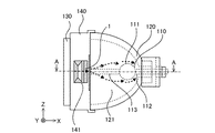
図1は、この発明の実施の形態1に係る光源装置を水平方向から見た側面図である。図1において、紙面向かって左右の方向で光軸と平行な方向をX方向、紙面向かって上下の方向をZ方向、紙面に垂直な方向をY方向とする。
図1における光源装置は、発光管110と、発光管110を内部に保持して且つ発光管110から放射された光を反射して、その光軸方向に出射する凹面反射鏡120と、凹面反射鏡120の開口部に取り付けられた前面ガラスホルダ140と、前面ガラスホルダ140に保持され、凹面反射鏡120の前面である開口部を覆う前面ガラス130と、前面ガラスホルダ140に設置された冷却風流入口部材1とからなる。
なお、図1では、説明の便宜上、凹面反射鏡120のみ透視可能にして凹面反射鏡120の内部を示している。また、点線の矢印は、冷却風流入口部材1から凹面反射鏡120内に流入した冷却風の流れを示す。
1 is a side view of a light source device according to
The light source device in FIG. 1 includes an
In FIG. 1, for convenience of explanation, only the concave reflecting
凹面反射鏡120は、X−Z平面における断面が楕円形状の回転楕円面鏡であり、結晶化ガラスまたは耐熱性のガラスからなる。凹面反射鏡120の内壁面には可視光のみを光軸方向に反射し、可視光以外の光を透過させる誘電体多層膜が蒸着されている。
The concave reflecting
前面ガラス130は耐熱性ガラスからなり、凹面反射鏡120の開口部を塞ぐように前面ガラスホルダ140により保持されている。前面ガラス130は透明材として作用し、発光管110から放射された光や凹面反射鏡120で反射された光を透過させ、かつ発光管110や凹面反射鏡120を外部から保護する。また、前面ガラス130のY−Z平面における直径は、凹面反射鏡120の開口部と同等の大きさであり、60〜90mm程度である。
前面ガラスホルダ140は、ガラス繊維入りの高耐熱難燃性樹脂や、アルミニウム合金、マグネシウム合金等からなり、凹面反射鏡120の開口部に係合している。また前面ガラスホルダ140には冷却風流入口141が設けられ、冷却風流入口141には冷却風流入口部材1が取り付けられている。冷却風流入口141は、発光管110の管球部111よりも前面ガラス130に近くなるよう設けられているが、管球部111よりも凹面反射鏡120の底面中央部に近くなるよう設けても良い。
なお、凹面反射鏡120および前面ガラスホルダ140は凹面部に相当し、冷却風流入口141は凹面部に形成された第1の開口部に相当する。
The
The concave reflecting
なお、図1においては、凹面反射鏡120に前面ガラスホルダ140を係合し、前面ガラスホルダ140に前面ガラス130を取り付けているが、前面ガラスホルダ140を使用しなくても良い。その場合は、凹面反射鏡120が前面ガラス130を直接保持し、凹面反射鏡120に冷却風流入口141を設ければ良い。
また、凹面反射鏡120と前面ガラスホルダ140とを一体化させて、前面ガラス130を保持させても良い。
In FIG. 1, the
Further, the concave reflecting
図2は、図1における発光管110として使用される超高圧水銀ランプのA-A線断面図である。図2において、発光管110は石英ガラス製であり、管球部111の両端に筒状の封止部112および113が形成されている。管球部111が凹面反射鏡120の焦点に位置するよう配置されるが、封止部112および113が凹面反射鏡120に固着されることにより、発光管110が凹面反射鏡120の内部空間121に定設される。封止部112および113にはモリブデン箔14および15が封じられている。モリブデン箔14には背面側外部電極16および背面側内部リード19が接続され、この背面側内部リード19にはタングステン製の電極12が接続されており、モリブデン箔15には先端側外部電極17および先端側内部リード20が接続され、この先端側内部リード20にはタングステン製の電極13が接続され、さらに先端側外部電極17には先端側リード線18が接続されている。
管球部111には水銀および始動性向上のためのバッファガスとしてアルゴンガス等の希ガスが所定量封入されている。
FIG. 2 is a cross-sectional view taken along line AA of the ultrahigh pressure mercury lamp used as the
The
ここでは、封止部112、モリブデン箔14、背面側外部電極16、背面側内部リード19およびタングステン製の電極12が第1の電極部を形成しており、封止部113、モリブデン箔15、先端側外部電極17、先端側内部リード20、タングステン製の電極13および先端側リード線18が第2の電極部を形成している。また、先端側外部電極17および先端側リード線18が第2の電極部の先端に相当する。
Here, the sealing
封止部112および113に封じる材料としてモリブデン箔14および15を使用する理由は、発光時の管球部111の内部が高圧(例えば、100気圧以上)になるため、外部に対する気密性が必要となるところ、モリブデンはその酸化物が石英ガラスにとけやすく、また石英ガラスに比べ線膨張係数が大きいので点灯時にモリブデン箔が塑性変形して気密性を保持できるためである。
The reason why the molybdenum foils 14 and 15 are used as the material sealed in the sealing
なお、発光管110には、超高圧水銀ランプの替わりにキセノンランプやメタルハライドランプ等その他の放電ランプを用いても良い。点灯駆動方式としては、直流方式または交流方式のいずれの方式であっても構わない。
For the
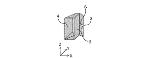
図3は、冷却風流入口141に設けられた冷却風流入口部材1を、冷却風の流入口側から見た斜視図である。冷却風流入口部材1は、第1の冷却風制御部材である先端部側導風フィン2と、第2の冷却風制御部材である管球部側導風フィン3と、導風ガイド4と、先端部側導風フィン2と導風ガイド4のZ方向における上辺および下辺に接合する上面および底面とからなる。
先端部側導風フィン2および管球部側導風フィン3は矩形状の平面であり、導風ガイド4は冷却風流入側を長辺および冷却風流出側を短辺とする台形の平面である。管球部側導風フィン3の一辺は、先端部側導風フィン2の延長線に対して所定の角度θをなして先端部側導風フィン2の一辺に取り付けられている。また、導風ガイド4は先端部側導風フィン2に略対向しており、先端部側導風フィン2、導風ガイド4、上面および底面により、冷却風の通過口が形成されている。
FIG. 3 is a perspective view of the cooling
The tip side
なお、図3においては、先端部側導風フィン2および管球部側導風フィン3を矩形状の平面とし、導風ガイド4を台形の平面としたが、これらの形状は図3の記載に限られず、例えば導風ガイド4も矩形にしたり、先端部側導風フィン2を導風ガイド4のように冷却風流入側を長辺および冷却風流出側を短辺とする台形にしたり、管球部側導風フィン3を角円四角形にしても良い。
また、導風ガイド4は、図3に示すように冷却風流入口部材1の一部であっても良いが、前面ガラスホルダ140と一体化させても良く、導風ガイド4を単独の部品として冷却風流入口141に取り付けても良い。
In FIG. 3, the tip side
Further, the
図3において、Y方向の(−)から(+)の向きに冷却風流入口部材1に流れ込んだ冷却風は、先端部側導風フィン2により左右に分割され、左側に進んだ冷却風は先端部側導風フィン2、導風ガイド4、上面および底面からなる通過口を通過し、右側に進んだ冷却風は管球部側導風フィン3に向きを変更される。冷却風の流れについては以降で図4を用いて説明する。
In FIG. 3, the cooling air flowing into the cooling
図4は、図1における光源装置を上から見た場合のA−A線断面図である。なお、図中において図1ないし図3と同一の構成には同一の符号を付し、その説明は省略する。
図4において、凹面鏡120の底面中央部には発光管110の封止部112が取り付けられ、封止部112の右端にあたる背面側外部電極16(図示せず)にはリード線(図示せず)が接続され、外部より電力が供給される。
4 is a cross-sectional view taken along line AA when the light source device in FIG. 1 is viewed from above. In addition, in the figure, the same code | symbol is attached | subjected to the structure same as FIG. 1 thru | or FIG. 3, and the description is abbreviate | omitted.
In FIG. 4, a sealing
前面ガラスホルダ140には、内部空間121に流入する冷却風が十分通過できる開口面積を持つ冷却風流入口141が形成され、図1で図示した冷却風流入口部材1が取り付けられているが、冷却風流入口141の凹面反射鏡120の外部側には冷却ダクト146が取り付けられ、冷却ダクト146の先には吸気ファン(図示せず)が接続されている。この吸気ファンはシロッコファン等の遠心ファンまたは軸流ファンである。
The
前面ガラスホルダ140において、光軸180を間にして冷却風流入口141に対向する箇所には冷却風が通過可能な冷却風排出口142が形成され、凹面反射鏡120の頸部にも冷却風の排出口となる頸部排出口122が形成されている。また、冷却風流入口141の冷却風流入口部材1、冷却風排出口142および頸部排出口122には、発光管110が万が一破裂したときの破片飛散防止用の防爆ネット143が取り付けられている。
冷却ダクト146から冷却風流入口141に設置された冷却風流入口部材1を通って内部空間121に流入した冷却風は、冷却風排出口142または頸部排出口122から凹面反射鏡120の外部に流出する。光源装置内の冷却風の流れを矢印で示す。
In the
The cooling air that has flowed into the
先端部側導風フィン2は、冷却風流入口141を光軸180に平行なX方向において2分割し、前面ガラス130に近い開口部と凹面反射鏡120の底面中央部に近い開口部とが形成される。分割された開口部のうち、前面ガラス130に近い開口部を第1の冷却風流入口144、凹面反射鏡120の底面中央部に近い開口部を第2の冷却風流入口145とする。つまり、冷却ダクト146から冷却風流入口部材1に流入する冷却風は、先端部側導風フィン2により、第1の冷却風流入口144から流入する冷却風W1と第2の冷却風流入口145から流入する冷却風W2とに分かれて内部空間121に流入する。
なお、冷却風W1およびW2は、第1の冷却風および第2の冷却風に相当する。
The front-end side
The cooling air W1 and W2 correspond to the first cooling air and the second cooling air.
第1の冷却風流入口144から内部空間121に流入する冷却風W1は、先端部側導風フィン2により先端側外部電極17および先端側リード線18に向かって流れる。さらに、導風フィン4は、略対向して位置する先端部側導風フィン2とともに冷却風W1を先端側外部電極17および先端側リード線18へ指向するよう整流する。
The cooling air W1 flowing into the
また、管球部側導風フィン3は、先端部側導風フィン2の内部空間121に近い端部に取り付けられ、先端部側導風フィン2の延在方向に対して凹面反射鏡120の底面中央部に向かって、つまりX(+)方向に向かって、所定の角度θをなしている。ここでは、冷却風流入口141おける凹面反射鏡120の内壁面に連なる第1の冷却風流入口144および第2の冷却風流入口145の開口面と管球部側導風フィン3とが略平行になっている。
さらに、管球部側導風フィン3の凹面反射鏡120の底面中央部に最も近い端部であり、先端部側導風フィン2への取り付け箇所を一辺とする辺に対向する辺である端面3aは、第2の冷却風流入口145の凹面反射鏡120の底面中央部に最も近い位置よりもX方向において凹面反射鏡120の底面中央部に近く、管球部側導風フィン3は、第2の冷却風流入口145を覆って流入する冷却風W2の向きを変えるように設置されている。
Further, the tube portion side
Furthermore, the end surface which is the end closest to the center of the bottom surface of the concave reflecting
次に、図4を用いて、内部空間121における冷却風の流れをさらに説明する。
第1の冷却風流入口144から流入した冷却風W1は、冷却ダクト146から内部空間121に流入する際、先端部側導風フィン2および導風ガイド4により整流されるだけなので、風速を保ったまま先端側外部電極17および先端側リード線18にぶつかり、先端側外部電極17および先端側リード線18を冷却する。その後、冷却風W1は、ある程度の風速を持って凹面反射鏡120の内壁面に突き当たり、矢印に示すように凹面鏡反射鏡120の内壁面に沿って流れる。このとき、冷却風W1は、先端側外部電極17および先端側リード線18にぶつかって風速や風向が乱されるため、風量が一様でない冷却風W1が管球部111に向かう。
Next, the flow of the cooling air in the
When the cooling air W1 flowing in from the first
一方、第2の冷却風流入口145から内部空間121に流入した冷却風W2の進行方向は、管球部側導風フィン3により、先端側外部電極17および先端側リード線18に向かう冷却風W1とは異なる向きに変更され、凹面反射鏡120の底面中央部に向かうよう整流される。整流された冷却風W2は、凹面反射鏡120の内壁面に沿って流れ、管球部111に向かう。その結果、冷却風W2は管球部111付近で冷却風W1と衝突する。
この衝突により、管球部111に向かう冷却風W1の風速、および冷却風W1同様に管球部111に向かう冷却風W2の風速が弱まり、冷却風は管球部111にぶつかる勢いを弱め、凹面反射鏡120の管球部111付近に滞留し、やがて冷却風排出口142または頸部排出口122から排出される。
On the other hand, the traveling direction of the cooling air W <b> 2 flowing into the
Due to this collision, the wind speed of the cooling air W1 toward the
このように、冷却風W2が冷却風W1の管球部111への流れを抑制する向きに流れることで、冷却風W1による管球部111の温度への影響、特に過冷却や、部分的な温度低下または温度上昇を抑制することができる。従って、管球部111の温度を適正に保ちながら先端側外部電極17および先端側リード線18を冷却して、発光管110の光の利用効率を保つことができる。
In this way, the cooling air W2 flows in a direction that suppresses the flow of the cooling air W1 to the
次に、第1の冷却風流入口144から内部空間121に流入する冷却風W1と第2の冷却風流入口145から内部空間121に流入する冷却風W2の調整について説明する。
Next, adjustment of the cooling air W1 flowing into the
まず、冷却風W1の管球部側導風フィン3からの影響について考える。
冷却風W1は、先端側外部電極17および先端側リード線18に向かって流れるが、冷却風W1は、先端部側導風フィン2に対して傾斜して取り付けられている管球部側導風フィン3により影響される場合がある。管球部側導風フィン3の先端部側導風フィン2に対する角度θが小さい場合、冷却風W1は、管球部側導風フィン3の壁面から十分剥離できず、管球部側導風フィン3の壁面から抵抗を受けたり、冷却風W2との分離が不十分になって冷却風W2の風速の影響を受けたりすることになる。すると、冷却風W1は風速を損失したり、先端側外部電極17および先端側リード線18からずれた方向へ向かったりして、先端側外部電極17および先端側リード線18の冷却不足が発生する。また、凹面反射鏡120の内壁面に向かう冷却風W1の風速も損失する。
さらに、冷却風W1との分離が不十分な冷却風W2は、凹面反射鏡120の内壁面に沿って管球部111に向かう風速を損失したり、凹面反射鏡120の内壁面に沿わずに冷却風W1の方向に向かって流れたりして、管球部111に向かう風速が損失する。
このように、管球部側導風フィン3の先端部側導風フィン2に対する角度によっては、冷却風W1およびW2の風速に影響が生じるため、二つの冷却風W1およびW2の流れを用いた発光管110の温度制御が困難になる場合が発生する。従って、先端側外部電極17および先端側リード線18を十分冷却すること、および管球部111の温度を適正に保つことを確実に行うには、管球部側導風フィン3の先端部側導風フィン2に対してなす角度θを一定以上にする必要がある。
First, the influence of the cooling air W1 from the tube portion side
The cooling air W1 flows toward the distal-end-side
Further, the cooling air W2 that is not sufficiently separated from the cooling air W1 loses the wind speed toward the
As described above, depending on the angle of the tube portion side
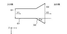
図5は、冷却風W1が管球部側導風フィン3から影響を受けないための角度θの許容範囲を求めるためのモデル図である。ここでは、風の入口側の内径より出口側の内径の方が大きい拡大出口管を用い、出口側壁面G2で形成される管部は、入口側の壁面G1で形成される管の先端部に、壁面G1の延長線に対して所定の角度θをなして広がるように取り付けられている。また、冷却風W1に相当する風をY方向の(−)から(+)へ流し、風の入口側の管径をD1、出口側の管径をD2、入口側の管中央部の風速をV1、出口側の管中央部の風速をV2とする。なお、壁面G1が先端部側導風フィン2に、壁面G2が管球部側導風フィン3に、壁面G1と壁面G2とのなす所定の角度θが図4における先端部側導風フィン2と管球部側導風フィン3とがなす角度θに相当するとみなす。
FIG. 5 is a model diagram for obtaining an allowable range of the angle θ so that the cooling air W <b> 1 is not affected by the tube portion side
図6は、図5における入口と出口の管径の比D2/D1を横軸、入口と出口の風速比V2/V1を縦軸にしたグラフであり、壁面G1と壁面G2のなす角度θが3.5°、6°、10°、15°、30°の場合の、入口と出口の管径の比D2/D1に対する風速比V2/V1の変化を示したものである。図6では、角度θが大きくなるに連れて、風速比V2/V1が1に近づいており、角度θが30°以上のときにV2/V1=1となっている。つまり、角度θが30°以上であれば、入口と出口の風速が変化しないことが分かる。 FIG. 6 is a graph in which the inlet / outlet pipe diameter ratio D2 / D1 in FIG. 5 is plotted on the horizontal axis and the inlet / outlet wind speed ratio V2 / V1 is plotted on the vertical axis, and the angle θ between the wall surface G1 and the wall surface G2 is The change of the wind speed ratio V2 / V1 with respect to ratio D2 / D1 of the pipe diameter of an inlet port in the case of 3.5 degrees, 6 degrees, 10 degrees, 15 degrees, and 30 degrees is shown. In FIG. 6, the wind speed ratio V2 / V1 approaches 1 as the angle θ increases, and V2 / V1 = 1 when the angle θ is 30 ° or more. That is, it can be seen that if the angle θ is 30 ° or more, the wind speed at the inlet and the outlet does not change.
さらに、図5における管径D1およびD2を固定にして、角度θを変化させた場合の風速比V2/V1を測定する。
図7は、図5における入口と出口の径をD1=5mm、D2=9.4mmにし、角度θを横軸として、角度θを変化させた場合の風速比V2/V1を求めたものである。図7においても、角度θが大きくなるに連れて、風速比V2/V1が1に近づいており、角度θが30°以上のときに風速比V2/V1=1となっている。
なお、図7は測定点に対して近似直線を引いたものであり、角度θが0°の場合は、管径の変化がない1本の管と同じ状態であるため、V2/V1は図7で示すように値が減少するのではなく、V2/V1=1になると考えられる。
Furthermore, the wind speed ratio V2 / V1 when the tube diameters D1 and D2 in FIG. 5 are fixed and the angle θ is changed is measured.
FIG. 7 shows the wind speed ratio V2 / V1 when the diameters of the inlet and the outlet in FIG. 5 are D1 = 5 mm and D2 = 9.4 mm, and the angle θ is changed with the angle θ as the horizontal axis. . Also in FIG. 7, the wind speed ratio V2 / V1 approaches 1 as the angle θ increases, and the wind speed ratio V2 / V1 = 1 when the angle θ is 30 ° or more.
Note that FIG. 7 is obtained by drawing an approximate straight line with respect to the measurement point. When the angle θ is 0 °, the state is the same as that of a single tube with no change in tube diameter, so V2 / V1 is It is considered that V2 / V1 = 1 instead of the value decreasing as indicated by 7.
図6および図7で示すように、壁面G2が壁面G1に対して傾いたところ、つまり角度θが0°より大きくなった時点から出口側の風速V2の減速が発生し、角度θを大きくするに連れて風速V2の減速が小さくなり、角度θが30°以上であれば、壁面G2が風の流れに影響を及ぼさなくなり、出口側で風速を全く失わないことが分かる。つまり、管球部側導風フィン3の先端部側導風フィン2に対する角度θを30°以上にすれば、冷却風W1は風速を失わずに管球部側導風フィン3から十分剥離でき、先端側外部電極17および先端側リード線18を十分冷却すること、および管球部111の温度を適正に保つことを確実に行える。反対に、角度θが30°より小さい場合は、冷却風W1は管球部側導風フィン3の影響を無視し得えないと考えられる。
As shown in FIGS. 6 and 7, when the wall surface G2 is inclined with respect to the wall surface G1, that is, when the angle θ is greater than 0 °, the wind speed V2 on the outlet side is decelerated and the angle θ is increased. Accordingly, it can be seen that when the deceleration of the wind speed V2 is reduced and the angle θ is 30 ° or more, the wall surface G2 does not affect the flow of the wind and the wind speed is not lost at the exit side. That is, if the angle θ of the tube portion side
さらに、冷却風W2の管球部側導風フィン3からの影響について考える。
図8は、管球部側導風フィン3の冷却風W2への影響を説明するための模式図である。図8において、風の入口側の壁面G3および出口側の壁面G4は、例えば矩形状の平面であり、壁面G4の一辺は、壁面G3の延長線に対して所定の角度θをなすよう、壁面G3の一辺に取り付けられている。ここでは、壁面G3が先端部側導風フィン2に、壁面G4が管球部側導風フィン3に、壁面G3と壁面G4とのなす所定の角度θが図4における先端部側導風フィン2と管球部側導風フィン3とがなす角度θに相当するとみなす。また、冷却風W2に相当する風を壁面G3よりX(+)側に流した場合の、入口側で壁面G3のZ方向における中央部での風速をV3、出口側で壁面G4のZ方向における中央部での風速をV4とし、壁面G3と壁面G4とがなす角度θの補角を角度θ1とする。
Further, the influence of the cooling air W2 from the tube portion side
FIG. 8 is a schematic diagram for explaining the influence of the tube portion side
図8において、冷却風W2がY方向の(−)から(+)の向きに風速V3で流入した場合、冷却風W2が壁面G4の影響を受けずに失速しないためには、角度θ1が30°以上である必要がある。これは、図5ないし図7で求めた冷却風W1が風速を損失しないための角度θが30°以上であることに基づくものである。角度θ1が30°以上であれば、速度V3で流入した冷却風W2は壁面G4から十分剥離することができ、冷却風W1と混じることもないため、冷却風W1の風速を弱めることがない。 In FIG. 8, when the cooling air W2 flows in from the (−) to (+) direction in the Y direction at the wind speed V3, the angle θ1 is 30 so that the cooling air W2 is not affected by the wall surface G4 and does not stall. Must be greater than °. This is based on the fact that the angle θ for preventing the cooling air W1 obtained in FIGS. 5 to 7 from losing the wind speed is 30 ° or more. If the angle θ1 is 30 ° or more, the cooling air W2 flowing in at the speed V3 can be sufficiently separated from the wall surface G4 and is not mixed with the cooling air W1, so that the wind speed of the cooling air W1 is not weakened.
このように、角度θの補角θ1が30°以上である必要があることから、角度θは150°以下であることが必要となる。つまり、管球部側導風フィン3の先端部側導風フィン2に対する角度θが30°以上150°以下であれば、冷却風W1が風速を弱めることなく、また風向を変えることなく先端側外部電極17および先端側リード線18を冷却することができる。
Thus, since the complementary angle θ1 of the angle θ needs to be 30 ° or more, the angle θ needs to be 150 ° or less. That is, if the angle θ of the tube portion side
次に、管球部側導風フィン3の幅について説明する。
図9(a)は図4における冷却風流入口部材1付近の拡大断面図である。図9(a)では、冷却風流入口141おける凹面反射鏡120の内壁面に連なる第1の冷却風流入口144および第2の冷却風流入口145の開口面と、管球部側導風フィン3とが略平行になっており、さらに管球部側導風フィン3における凹面反射鏡120の底面中央部に最も近い端面3aは、第2の冷却風流入口145の凹面反射鏡120の底面中央部に最も近い位置のY方向への延長線L1よりも、凹面反射鏡120の底面中央部に近くなるよう位置している。この場合、第2の冷却風流入口145から流入した冷却風W2は、第2の冷却風流入口145への流入直後には冷却風W1と同様に先端側外部電極17および先端側リード線18に向かっていた流れを、管球部側導風フィン3により凹面反射鏡120の底面中央部に向かうよう変えられる。この後、冷却風W2は、凹面反射鏡120の内壁面に沿って管球部111(図示せず)に向かう。
Next, the width of the tube portion side
FIG. 9A is an enlarged sectional view of the vicinity of the cooling
図9(b)は、冷却風流入口部材1のもう一つの形態を示したものである。図9(a)に比べて、管球部側導風フィン3の幅が長く、角度θは小さい。このようにした場合でも、冷却風W2は進行方向を変えられ、凹面反射鏡120の内壁に沿って管球部111に向かうことができる。
つまり、図9(a)や図9(b)に示すように、端面3aが、第2の冷却風流入口145の凹面反射鏡120の底面中央部に最も近い位置のY方向への延長線L1よりも、凹面反射鏡120の底面中央部に近くなるよう位置していれば、冷却風W2を凹面反射鏡120の内壁面に沿って進むように風向を変えることができ、管球部111に向かう冷却風W1に衝突させることができる。
FIG. 9 (b) shows another form of the cooling
That is, as shown in FIGS. 9A and 9B, the
なお、図4では、冷却風流入口141において、冷却風が前面ガラス130に近い方から凹面反射鏡120の底面中央部に向かって流入する場合、つまりX方向における(−)から(+)に向かっていたが、冷却風流入口141に流入する冷却風の向きを変えても良い。
In FIG. 4, in the cooling
図10は、図4における冷却風流入口141に流入する風を、凹面反射鏡120の底面中央部から前面ガラス130に向かって、つまりX方向における(+)から(−)に向かって流入する場合の光学装置の断面図を示したものである。なお、図中において図4と同一の構成には同一の符号を付し、その説明は省略する。これは、図10に示すように発光管110の先端側外部電極17および先端側リード線18が、図4における先端側外部電極17および先端側リード線18よりも前面ガラス130に近い場合に、先端側外部電極17および先端側リード線18に冷却風を十分送風するために有効な形態である。
FIG. 10 shows the case where the air flowing into the cooling
図10において、第1の冷却風流入口144から内部空間121に流入した冷却風W1は、前面ガラス130の近くに位置する先端側外部電極17および先端側リード線18に向かって流れ、先端側外部電極17および先端側リード線18を冷却した後、冷却風W1の進行方向にある冷却風排出口142から凹面反射鏡120の外部に排出されるか、先端側外部電極17および先端側リード線18、前面ガラス130等で進行方向を変えられて凹面反射鏡120の内壁面に沿って管球部111に向かって流れる。
一方、第2の冷却風流入口145から内部空間121に流入した冷却風W2は、管球部側導風フィン3により、進行方向を先端側外部電極17および先端側リード線18への向きから、凹面反射鏡120の底面中央部に向うよう変えられ、凹面反射鏡120の内壁面に沿って管球部111に向かう。
その後の冷却風W1およびW2の動作は、前述の図4を用いた冷却風W1およびW2の説明と同様である。
In FIG. 10, the cooling air W1 flowing into the
On the other hand, the cooling air W2 flowing into the
Subsequent operations of the cooling air W1 and W2 are the same as the description of the cooling air W1 and W2 using FIG. 4 described above.
この場合も、冷却風W1を管球部側導風フィン3から十分剥離させて先端側外部電極17および先端側リード線18を効果的に冷却するためには、先端部側導風フィン2と管球部側導風フィン3とのなす角度θを30°以上150°以下にすることが望ましい。また、冷却風W2を凹面反射鏡120の内壁面に沿って進ませて、管球部111に向かわせるには、端面3aが、冷却風流入口141の凹面反射鏡120の底面中央部に最も近い位置のY方向への延長線L1よりも、凹面反射鏡120の底面中央部に近く位置していれば良い。
もちろん、冷却風流入口141の風の向きは、図4や図10に示すように光軸180に対して斜めでも良いが、光軸180に対して垂直方向であっても良い。
Also in this case, in order to sufficiently separate the cooling air W1 from the tube portion side
Of course, the wind direction of the cooling
また、上述の説明では、前面ガラスホルダ140の一部に冷却風流入口141を形成し、冷却風流入口141に先端部側導風フィン2および管球部側導風フィン3を設けることで、第1の冷却風流入口144および第2の冷却風流入口145を形成し、冷却風W1と冷却風W2を内部空間121に流入していた。しかし、先端側外部電極17および先端側リード線18に指向する冷却風を流入する流入口、および凹面反射鏡120に沿って管球部111に向かって流れる冷却風W1に指向する冷却風W2を流入する流入口でありさえすれば、先端部側導風フィン2や管球部側導風フィン3などを用いなくても良く、例えばノズル状の送風口を第1の冷却風流入口および第2の冷却風流入口としても良い。
さらには、第1の冷却風流入口144と第2の冷却風流入口145とを光軸180方向において平行に配置していたが、各冷却風流入口を分離して配置しても良い。例えば、第1の冷却風流入口144は図4と同様、前面ガラスホルダ140の一部に形成し、第2の冷却風流入口145は図4における冷却風排出口142の位置に形成するなどである。
Further, in the above description, the cooling
Furthermore, although the first
以上のように、この実施の形態1によれば、回転式カラーフィルタや光密度均一化手段などの光学部品の向きや配置順を変えることがなく、従来から使用している凹面反射鏡120や前面ガラスホルダ140に冷却風流入口141を設ける構成なので、光源装置が大型化せず、さらにそれに伴う光の利用効率が低下することがない。
As described above, according to the first embodiment, the concave reflecting
また、先端側外部電極17および先端側リード線18に指向する冷却風W1を内部空間121に流入し、先端側外部電極17および先端側リード線18にぶつかった後の冷却風W1に指向する冷却風W2を内部空間121に流入するので、冷却風W2が管球部111に向かう冷却風W1の流れを抑制し、冷却風W1による管球部111の温度への影響、特に過冷却や、部分的な温度低下または温度上昇を抑制することができる。従って、管球部111の温度を適正に保ちながら先端側外部電極17および先端側リード線18を十分冷却して温度上昇を防ぐことができる。つまり発光管110を理想的に冷却して発光効率を高め、高輝度かつ長寿命の光源装置を得ることができる。
Further, the cooling air W1 directed to the distal
また、先端部側導風フィン2に対して管球部側導風フィン3の取り付け角度θを30°以上150°以下にすることで、先端側外部電極17および先端側リード線18に指向する冷却風W1を管球部側導風フィン3から十分剥離して、速度を損失させないため、先端側外部電極17および先端側リード線18を効果的に冷却することができる。
Further, by setting the attachment angle θ of the tube portion side
さらに、管球部側導風フィン3の凹面反射鏡120の底面中央部に最も近い端面3aを、第2の冷却風流入口145の凹面反射鏡120の底面中央部に最も近い位置よりも凹面反射鏡120の底面中央部に近くに位置させるので、冷却風W2を凹面反射鏡120の内壁面に沿わせ、管球部111に向かう冷却風W1に指向して、冷却風W1の管球部111への影響を弱めて管球部111の過冷却を防ぐことができる。
Further, the
実施の形態2.
実施の形態1では、冷却風流入口部材1において、管球部側導風フィン3の一辺を先端部側導風フィン2の一辺に取り付けており、さらに、図9のように、管球部側導風フィン3の凹面反射鏡120の底面中央部に最も近い端面3aを、第2の冷却風流入口145の凹面反射鏡120の底面中央部に最も近い位置よりも凹面反射鏡120の底面中央部に近くなるよう位置させていた。これにより、第2の冷却風流入口145から流入した冷却風W2を凹面反射鏡120の内壁面に沿って管球部111に向かわせていた。
この実施の形態2では、第2の冷却風流入口145の凹面反射鏡120の底面中央部に最も近い位置の方が、管球部側導風フィン3の凹面反射鏡120の底面中央部に最も近い端面3aよりも凹面反射鏡120の底面中央部に近くなるよう位置させる。
In the first embodiment, in the cooling
In the second embodiment, the position closest to the center of the bottom surface of the
図11は、実施の形態2に係る光源装置を上から見た場合のX−Y平面の断面図であり、図12は、実施の形態2に係る冷却風流入口部材1を、冷却風の流入口側から見た斜視図であり、図13(a)は図11における冷却風流入口部材1付近の拡大断面図である。なお、図11、図12および図13(a)において、図4、図3および図9(a)と同一の構成には同一の符号を付し、その説明は省略する。
FIG. 11 is a cross-sectional view of the XY plane when the light source device according to the second embodiment is viewed from above, and FIG. 12 shows the cooling
図13(a)では、管球部側導風フィン3の凹面反射鏡120の底面中央部に最も近い端面3aは、第2の冷却風流入口145の凹面反射鏡120の底面中央部に最も近い位置のY方向への延長線L1よりも、前面ガラス130に近くなるよう位置している。この場合、第2の冷却風流入口145から流入した冷却風W2は、実施の形態1のように凹面反射鏡120の内壁面に沿って緩やかに流れずに、矢印で示すように内部空間121に拡散しながら管球部111(図示せず)に向けて吹き込む。
また、管球部側導風フィン3の凹面反射鏡120の底面中央部に最も近い端面3aが、第2の冷却風流入口145の凹面反射鏡120の底面中央部に最も近い位置のY方向への延長線L1よりも、前面ガラス130に近くなるよう位置するのであれば、管球部側導風フィン3の幅や先端部側導風フィン2との角度θが、図13(a)における管球部側導風フィン3の幅や角度θと異なっても良い。例えば、図13(b)が示すように、図13(a)よりも管球部側導風フィン3の幅を短く、角度θを大きくして、管球部側導風フィン3が凹面反射鏡120の第2の冷却風流入口145付近での内壁面と略平行に配置するなどである。
In FIG. 13A, the
Further, the
図11において、管球部111に向けて吹き込んだ冷却風W2は、その流れを急激に拡散しながら管球部111に到達するが、冷却風W2の一部は管球部111に到達する前の冷却風W1に衝突し、冷却風W1の流れを抑制する。このため、第1の冷却風流入口144から流れ込み、外部電極17や先端側リード線18、封止部113等により風速を乱された一様でない風量の冷却風W1が管球部111に到達して管球部111を部分的に直接冷却することを抑制でき、管球部111を均一に冷却することが可能となる。
In FIG. 11, the cooling air W <b> 2 blown toward the
また、この実施の形態2においては、冷却風W1および冷却風W2が凹面反射鏡120の内壁面に沿って流れることで、冷却風が凹面反射鏡120の底面中央部に多く向かっていた実施の形態1と比較して、凹面反射鏡120の底面中央部に向かう冷却風が減少する。つまり、封止部112の根本付近へ向かう冷却風が減少するため、封止部112の根本付近の温度が相対的に高くなる。このことにより、封止部112付近の熱勾配が緩やかになり、熱勾配の急激な変化により封止部112付近を起点とする破裂が発生しやすい光源装置においては破裂低減の効果がある。
Further, in the second embodiment, the cooling air W1 and the cooling air W2 flow along the inner wall surface of the concave reflecting
以上のように、この実施の形態2によれば、冷却風W2を管球部111に向けて吹き込ませるので、管球部111に到達する前の冷却風W1に冷却風W2が直接作用して、冷却風W1が管球部111に衝突して直接冷却することを抑制でき、管球部111を均一に冷却することが可能となる。従って、管球部111の温度をさらに適正に保ちながら先端側外部電極17および先端側リード線18を十分冷却して温度上昇を防ぎ、発光管110の発光効率を高め、高輝度かつ長寿命の光源装置を得ることができる。
As described above, according to the second embodiment, since the cooling air W2 is blown toward the
また、凹面反射鏡120の底面中央部付近に到達する冷却風が減少するので、封止部112の温度勾配を緩やかにして、発光管110の破裂を防ぐことができる。
In addition, since the cooling air that reaches the vicinity of the center of the bottom surface of the concave reflecting
実施の形態3.
実施の形態1および実施の形態2では、管球部側導風フィン3は、第2の冷却風流入口145から内部空間121に流入した冷却風W2の方向を変化させる面状の部材であったが、この実施の形態3では、管球部側導風フィン3に第2の冷却風が通過する第2の開口部を設ける。
In the first embodiment and the second embodiment, the tube portion side
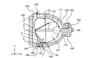
図14は、実施の形態3に係る光源装置を上から見た場合のX−Y平面の断面図であり、図15は、実施の形態3に係る冷却風流入口部材1を、冷却風の流入口側から見た斜視図である。なお、図14および図15において、図11および図12と同一の構成には同一の符号を付し、その説明は省略する。
FIG. 14 is a cross-sectional view of the XY plane when the light source device according to the third embodiment is viewed from above, and FIG. 15 shows the cooling
図15において、冷却風流入口部材1を構成する管球部側導風フィン3のほぼ中央部には第2の開口部としてスリットSが設けられており、図14において、第2の冷却風流入口145から内部空間121に流入した冷却風W2は、実施の形態2と同様に管球部111に向けて吹き込む他、スリットSから第2の電極部の一部である封止部113に向けても吹き込む。これにより、実施の形態1および実施の形態2では冷却風が送風されずに冷却不足になりがちになる封止部113を十分冷却することができる。さらにこの封止部113が冷却されることにより、封止部113および管球部111の内部で接続されている電極13も冷却される。
電極13が冷却されると、光源消灯時に電極13への水銀付着量が増加し、管球部111の内壁に付着する水銀が減少する。すると、光源点灯時に電極13から管球部111の内壁に付着した水銀への異常放電の発生が減少し、それに伴う管球部111の内壁の黒化が発生しにくくなり、光の利用効率の低下を防ぐことができる。
In FIG. 15, a slit S is provided as a second opening at a substantially central portion of the tube portion side
When the
なお、図14および図15では、管球部側導風フィン3の凹面反射鏡120の底面中央部に最も近い端面3aを、第2の冷却風流入口145の凹面反射鏡120の底面中央部に最も近い位置よりも前面ガラス130の近くになるよう位置させて、冷却風W2を管球部111に吹き込ませていた。しかし、実施の形態1と同様に、管球部側導風フィン3の凹面反射鏡120の底面中央部に最も近い端面3aを、第2の冷却風流入口145の凹面反射鏡120の底面中央部に最も近い位置よりも凹面反射鏡120の底面中央部の近くになるよう位置させて、冷却風W2を凹面反射鏡120の内壁面に沿って管球部111に流れさせても良い。
14 and 15, the
以上のように、この実施の形態3によれば、管球部側導風フィン3のほぼ中央部にスリットSを設けたので、発光管110の封止部113および先端側電極13も十分冷却されて管球部111の内壁の黒化が発生しにくくなり、発光管110の発光効率を保ち、高輝度かつ寿命の長い光源装置を得ることができる。
As described above, according to the third embodiment, since the slit S is provided in the substantially central portion of the tube portion side
実施の形態4.
実施の形態3では、管球部側導風フィン3に、第2の開口部としてスリットSを設けたが、この実施の形態4では、矩形状の切り欠きを、管球部側導風フィン3の上部または下部に設ける。
In
図16は、実施の形態4に係る光源装置を上から見た場合のX−Y平面の断面図であり、図17は、実施の形態4に係る冷却風流入口部材1を、冷却風の流入口側から見た斜視図である。なお、図16および図17において、図14および図15と同一の構成には同一の符号を付し、その説明は省略する。
FIG. 16 is a cross-sectional view of the XY plane when the light source device according to the fourth embodiment is viewed from above. FIG. 17 shows the cooling
図17において、管球部側導風フィン3のZ方向における下部には矩形状の切り欠きが設けられており、図16において、第2の冷却風流入口145から内部空間121に流入した冷却風W2は、矩形状の切り欠き部分から大量に流入する。つまり、冷却を必要とする箇所に、矩形状切り欠き部から冷却風W2を流入して向かわせることができる。これにより、図16において、冷却風流入口1から内部空間121に吹き込む冷却風にZ方向の上下における風量の偏りが生じている場合には、管球部側導風フィン3の風量の少ない箇所に切り欠き部を設ければ、冷却風W2が切り欠き部から内部空間121に流れ込み、先端部側外部電極17および先端側リード線18などの発光管110の先端部を冷却するため、冷却風W1による冷却が足りない箇所を冷却することができる。また、発光管110が凹面反射鏡120の中心からずれている場合、例えばZ方向の上下のいずれかにずれている場合でも、管球部側導風フィン3において発光管110がずれている方向に近い部分に切り欠き部を設ければ、冷却風W1の向きが発光管110への向きとずれるために生ずる発光管110の冷却不足を、切り欠き部から流入した冷却風W2で補うことができる。
つまり、冷却風W1やW2のZ方向の上下における風量の偏りにより生ずる冷却の不均一を矯正し、管球部111や外部電極17および先端側リード線18などの発光管110の各部分を均一に冷却することができる。
17, a rectangular cutout is provided in the lower part in the Z direction of the tube portion side
In other words, the cooling non-uniformity caused by the deviation of the air flow in the vertical direction in the Z direction of the cooling air W1 and W2 is corrected, and each part of the
なお、図17では管球部側導風フィン3において下部の一部を切り欠いた例を示しているが、上部を切り欠いても構わない。また、管球部側導風フィン3を上部および下部の2つの部分に分割する他、3分割または4分割等して、その一部を切り欠いても良い。
In addition, although the example which notched a part of lower part in the tube part side
以上のように、この実施の形態4によれば、管球部側導風フィン3の一部を切り欠いているので、冷却風の流入時の偏りを矯正し、発光管110の各部分を均一に冷却することができる。これにより、発光管110の発光効率を高め、高輝度かつ寿命の長い光源装置を得ることができる。
As described above, according to the fourth embodiment, a portion of the tube portion side
実施の形態5.
図18は、実施の形態1ないし実施の形態4で示した光源装置を内装した単板フィールドシーケンシャル方式のプロジェクタ200を上から見た図である。図18において、光源装置を構成する凹面反射鏡120はハウジング201に収納されており、ハウジング201には排気ファン202を備えた排気口203が接続され、さらに光源装置に接続された冷却ダクト146には、内部空間121に冷却風を送り込む吸気ファン204が接続されている。
また、前面ガラス130の前面には、紫外線フィルタ150、回転式カラーフィルタ160、光密度均一化手段170、光を透過または反射する素子を備えた光学ユニット205が配されている。
Embodiment 5 FIG.
FIG. 18 is a top view of a single-plate field
Further, an
前面ガラス130から出射した光は、紫外線フィルタ150、回転式カラーフィルタ160、光密度均一化手段170、および光学ユニット205を透過して、光学ユニット205の対面に設けられたスクリーン206上に投射される。なお、図中の点線矢印は光の投射方向を示している。
The light emitted from the
一方、吸気ファン204で内部空間121に取り込まれた冷却風は、冷却風排出口142または頸部排出口122から凹面反射鏡120の外部でハウジング201内に排出され、さらに排気ファン202により排気口203からプロジェクタ200の外部に排出される。内部空間121での冷却風の流れ方については上記の各実施の形態で説明してあるため、説明を省略する。
なお、内部空間121に冷却風を送り込む吸気ファン204は、プロジェクタ200内部の空気を冷却風として取り込んでも良く、吸気ファン204をプロジェクタ200外部と接続してプロジェクタ200外部の空気を冷却風として取り込んでも良い。また吸気ファン204に冷却装置を設けて、冷却装置が生成した冷却風を取り込んでも良い。
On the other hand, the cooling air taken into the
Note that the
以上のように、この実施の形態5によれば、単板フィールドシーケンシャル方式のプロジェクタ200にこの発明に係る光源装置を内装するので、発光管110の各部の温度を理想的に保って発光効率を高め、高輝度かつ長寿命なプロジェクタを実現することができる。
As described above, according to the fifth embodiment, since the light source device according to the present invention is built in the single-plate field
17 外部電極、18 先端側リード線、110 発光管、111 管球部、120 凹面反射鏡、121 凹面反射鏡の内部空間、130 透明材、144 第1の冷却風流入口、145 第2の冷却風流入口
DESCRIPTION OF
Claims (10)
この凹面部の前記開口を覆う透明材、
管球部に対向して配置された一対の第1の電極部および第2の電極部からなり、第1の電極部を前記凹面部の底面中央部に配置された発光管、
前記空間に位置する前記第2の電極部の先端に指向する第1の冷却風を流入する第1の冷却風流入口、
前記第2の電極部の先端に到達した後に前記管球部に向かう前記第1の冷却風と衝突する、第2の冷却風を流入する第2の冷却風流入口、
凹面部の空間に冷却風を流入させるように前記凹面部に形成された第1の開口部、
この第1の開口部のうち、透明材に近い部分を第1の冷却風流入口と、前記凹面部の底面中央部に近い部分を第2の冷却風流入口と、なるよう、前記第1の開口部を前記凹面部の光軸方向において前記透明材に近い側と遠い側とに分割すると共に、前記第1の冷却風流入口に流入する第1の冷却風を第2の電極部の先端に指向させる第1の冷却風制御部材、
この第1の冷却風制御部材が延在する方向から前記凹面部の底面中央部に向かって所定の角度で傾斜するように前記第1の冷却風制御部材の前記空間に近い端部に取り付けられ、前記第2の冷却風流入口から前記空間に入った第2の冷却風の進行方向を、前記第1の冷却風と衝突するように変える第2の冷却風制御部材、
を備えたことを特徴とする光源装置。 A concave surface portion having a space where one surface is open with a curved region that reflects light,
A transparent material covering the opening of the concave surface,
An arc tube comprising a pair of first electrode portion and second electrode portion disposed to face the tube portion, wherein the first electrode portion is disposed at the center of the bottom surface of the concave surface portion,
A first cooling air inflow port for flowing in a first cooling air directed to a tip of the second electrode portion located in the space;
A second cooling air inlet into which the second cooling air flows, which collides with the first cooling air toward the tube portion after reaching the tip of the second electrode portion ;
A first opening formed in the concave portion so as to allow cooling air to flow into the space of the concave portion,
Of the first opening, the first opening has a portion close to the transparent material as a first cooling air inlet and a portion near the center of the bottom surface of the concave portion as a second cooling air inlet. The first cooling air flowing into the first cooling air inlet is directed to the tip of the second electrode portion, and the first cooling air flowing into the first cooling air inlet is divided into a portion close to and far from the transparent material in the optical axis direction of the concave surface portion. A first cooling air control member for causing
The first cooling air control member is attached to an end portion of the first cooling air control member close to the space so as to incline at a predetermined angle from the extending direction toward the bottom surface central portion of the concave surface portion. A second cooling air control member that changes a traveling direction of the second cooling air that has entered the space from the second cooling air inlet so as to collide with the first cooling air;
A light source device comprising:
Priority Applications (1)
| Application Number | Priority Date | Filing Date | Title |
|---|---|---|---|
| JP2005347903A JP4569454B2 (en) | 2005-12-01 | 2005-12-01 | Light source device and projector |
Applications Claiming Priority (1)
| Application Number | Priority Date | Filing Date | Title |
|---|---|---|---|
| JP2005347903A JP4569454B2 (en) | 2005-12-01 | 2005-12-01 | Light source device and projector |
Publications (3)
| Publication Number | Publication Date |
|---|---|
| JP2007157385A JP2007157385A (en) | 2007-06-21 |
| JP2007157385A5 JP2007157385A5 (en) | 2007-12-20 |
| JP4569454B2 true JP4569454B2 (en) | 2010-10-27 |
Family
ID=38241507
Family Applications (1)
| Application Number | Title | Priority Date | Filing Date |
|---|---|---|---|
| JP2005347903A Expired - Fee Related JP4569454B2 (en) | 2005-12-01 | 2005-12-01 | Light source device and projector |
Country Status (1)
| Country | Link |
|---|---|
| JP (1) | JP4569454B2 (en) |
Cited By (1)
| Publication number | Priority date | Publication date | Assignee | Title |
|---|---|---|---|---|
| KR101882449B1 (en) * | 2018-01-19 | 2018-07-27 | 더좋은생활 주식회사 | Modular LED lighting including an air guide to create an air stream |
Families Citing this family (10)
| Publication number | Priority date | Publication date | Assignee | Title |
|---|---|---|---|---|
| JP4877822B2 (en) * | 2007-07-31 | 2012-02-15 | 三洋電機株式会社 | Projection display device |
| JP4759758B2 (en) * | 2007-11-19 | 2011-08-31 | Necディスプレイソリューションズ株式会社 | Projection display |
| JP2010177157A (en) * | 2009-02-02 | 2010-08-12 | Seiko Epson Corp | Lamp unit, and projector |
| WO2011111186A1 (en) * | 2010-03-10 | 2011-09-15 | Necディスプレイソリューションズ株式会社 | Light source device and projection-type display device |
| JP6039878B2 (en) | 2010-03-24 | 2016-12-07 | セイコーエプソン株式会社 | Light source device and projector |
| JP2013012389A (en) * | 2011-06-29 | 2013-01-17 | Ushio Inc | Light source element |
| JP5815044B2 (en) * | 2011-11-21 | 2015-11-17 | 日立マクセル株式会社 | Projector device |
| JP5935419B2 (en) * | 2012-03-15 | 2016-06-15 | 岩崎電気株式会社 | Light irradiation device |
| CN103807810B (en) | 2012-11-14 | 2015-07-29 | 深圳市光峰光电技术有限公司 | Wavelength converter and related lighting fixtures |
| JP2017003705A (en) * | 2015-06-08 | 2017-01-05 | 株式会社リコー | Light source cooling device and image projection device with same |
Citations (4)
| Publication number | Priority date | Publication date | Assignee | Title |
|---|---|---|---|---|
| JPH02138496U (en) * | 1989-04-21 | 1990-11-19 | ||
| JPH06338212A (en) * | 1993-05-31 | 1994-12-06 | Iwasaki Electric Co Ltd | Cooling method and cooler for small-sized metal halide lamp |
| JP2005316177A (en) * | 2004-04-28 | 2005-11-10 | Toshiba Corp | Lamp unit and projection type display device |
| JP2006243635A (en) * | 2005-03-07 | 2006-09-14 | Casio Comput Co Ltd | Light source device and projector provided with it |
-
2005
- 2005-12-01 JP JP2005347903A patent/JP4569454B2/en not_active Expired - Fee Related
Patent Citations (4)
| Publication number | Priority date | Publication date | Assignee | Title |
|---|---|---|---|---|
| JPH02138496U (en) * | 1989-04-21 | 1990-11-19 | ||
| JPH06338212A (en) * | 1993-05-31 | 1994-12-06 | Iwasaki Electric Co Ltd | Cooling method and cooler for small-sized metal halide lamp |
| JP2005316177A (en) * | 2004-04-28 | 2005-11-10 | Toshiba Corp | Lamp unit and projection type display device |
| JP2006243635A (en) * | 2005-03-07 | 2006-09-14 | Casio Comput Co Ltd | Light source device and projector provided with it |
Cited By (1)
| Publication number | Priority date | Publication date | Assignee | Title |
|---|---|---|---|---|
| KR101882449B1 (en) * | 2018-01-19 | 2018-07-27 | 더좋은생활 주식회사 | Modular LED lighting including an air guide to create an air stream |
Also Published As
| Publication number | Publication date |
|---|---|
| JP2007157385A (en) | 2007-06-21 |
Similar Documents
| Publication | Publication Date | Title |
|---|---|---|
| JP4569454B2 (en) | Light source device and projector | |
| JP6039878B2 (en) | Light source device and projector | |
| JP2006267622A (en) | Lamp cooling device and projection type display device | |
| US20040145896A1 (en) | Light source device | |
| JP2000292859A (en) | Light source device | |
| JP5488293B2 (en) | Light source device and projector | |
| US7222970B2 (en) | Lamp unit and projection-type display apparatus | |
| JP2005107470A (en) | Light source device | |
| JP4613885B2 (en) | Lamp with reflector | |
| JP2009129590A (en) | Light source device | |
| JPH1139934A (en) | Light source unit | |
| JP4273912B2 (en) | Light source device | |
| JP2005173085A (en) | Light source device and projector using the same | |
| JP4082908B2 (en) | Light source device and cooling method of light source device | |
| JP2007080796A (en) | Light source lamp | |
| JP2005062376A (en) | Light source unit and projector employing same | |
| EP1862729A1 (en) | Light source device | |
| US8044559B2 (en) | Discharge lamp of the short arc type and a light source device having the discharge lamp of the short arc type | |
| US20040095765A1 (en) | Light source unit and reflecting mirror | |
| JP2008016394A (en) | Light source device, lighting device, and projector device | |
| JP2005309121A (en) | Light source apparatus, and projector equipped with the same | |
| JPH08114857A (en) | Light source device | |
| JPS61294753A (en) | Short-arc type discharge lamp device | |
| JP2004158447A (en) | Lamp with reflection mirror, and image projection device | |
| JP3752847B2 (en) | Light source unit |
Legal Events
| Date | Code | Title | Description |
|---|---|---|---|
| A521 | Written amendment |
Free format text: JAPANESE INTERMEDIATE CODE: A523 Effective date: 20071102 |
|
| A621 | Written request for application examination |
Free format text: JAPANESE INTERMEDIATE CODE: A621 Effective date: 20071102 |
|
| A977 | Report on retrieval |
Free format text: JAPANESE INTERMEDIATE CODE: A971007 Effective date: 20090911 |
|
| A131 | Notification of reasons for refusal |
Free format text: JAPANESE INTERMEDIATE CODE: A131 Effective date: 20091222 |
|
| A521 | Written amendment |
Free format text: JAPANESE INTERMEDIATE CODE: A523 Effective date: 20100120 |
|
| TRDD | Decision of grant or rejection written | ||
| A01 | Written decision to grant a patent or to grant a registration (utility model) |
Free format text: JAPANESE INTERMEDIATE CODE: A01 Effective date: 20100713 |
|
| A01 | Written decision to grant a patent or to grant a registration (utility model) |
Free format text: JAPANESE INTERMEDIATE CODE: A01 |
|
| A61 | First payment of annual fees (during grant procedure) |
Free format text: JAPANESE INTERMEDIATE CODE: A61 Effective date: 20100726 |
|
| FPAY | Renewal fee payment (event date is renewal date of database) |
Free format text: PAYMENT UNTIL: 20130820 Year of fee payment: 3 |
|
| FPAY | Renewal fee payment (event date is renewal date of database) |
Free format text: PAYMENT UNTIL: 20130820 Year of fee payment: 3 |
|
| R250 | Receipt of annual fees |
Free format text: JAPANESE INTERMEDIATE CODE: R250 |
|
| R250 | Receipt of annual fees |
Free format text: JAPANESE INTERMEDIATE CODE: R250 |
|
| LAPS | Cancellation because of no payment of annual fees |