JP4568428B2 - Closure to make it clear that it has been tampered with, and its method - Google Patents
Closure to make it clear that it has been tampered with, and its method Download PDFInfo
- Publication number
- JP4568428B2 JP4568428B2 JP2000551997A JP2000551997A JP4568428B2 JP 4568428 B2 JP4568428 B2 JP 4568428B2 JP 2000551997 A JP2000551997 A JP 2000551997A JP 2000551997 A JP2000551997 A JP 2000551997A JP 4568428 B2 JP4568428 B2 JP 4568428B2
- Authority
- JP
- Japan
- Prior art keywords
- bag
- neck
- belts
- pair
- air
- Prior art date
- Legal status (The legal status is an assumption and is not a legal conclusion. Google has not performed a legal analysis and makes no representation as to the accuracy of the status listed.)
- Expired - Fee Related
Links
Images


Classifications
-
- B—PERFORMING OPERATIONS; TRANSPORTING
- B65—CONVEYING; PACKING; STORING; HANDLING THIN OR FILAMENTARY MATERIAL
- B65B—MACHINES, APPARATUS OR DEVICES FOR, OR METHODS OF, PACKAGING ARTICLES OR MATERIALS; UNPACKING
- B65B51/00—Devices for, or methods of, sealing or securing package folds or closures; Devices for gathering or twisting wrappers, or necks of bags
Description
【0001】
〔技術分野〕
この発明は、袋のすぼめられた首の周りにリボンを巻き付けて、可撓性袋の首を閉じてシールするためにリボンを捩るための装置に対するいたずら防止クロージャアタッチメント補機に関する。
〔背景技術〕
米国特許第 3,138,904号(発明の名称:パッケージ及びラップ材料をひも結びする方法及び装置)と、米国特許第 3,059,670号(発明の名称:針金捩り装置)と、米国特許第 3,919,829号(パッケージ及びラップ材料をひも結びするための装置)と、米国特許第 4,856,258号(発明の名称:針金結束装置)と、米国特許第 5,483,134号(発明の名称:袋結束装置用リボン感知装置)は、袋の首の周りに針金状のリボンを取り付けて、これを捩ることによってプラスチック袋を閉じるのに用いられる装置を開示している。
【0002】
上述した特許に開示された種類の袋結束(ひも掛け)装置は、オクラホマ州、MaysvillのBufordコーポレーションから入手することができる。この結束装置は、一般的に、例えば約108フィート/分の速度で1分当たり100個以上のパッケージを作る速度で、塊のパンのようなパッケージを受け入れるように作られている。
【0003】
パン製品、紙片、氷を入れるプラスチック袋は、袋の首の周りの捩ったリボンを取り除くことによって、袋の内容物にアクセスするために簡単にあけることができる。この袋は、手で、袋の首の周りにリボンを再び置いてこれを捩ることによって再びシールすることができる。
【0004】
米国特許第 5,600,938号は、内容物を入れたプラスチック袋の平らになった開口端を横断する複数の間隔を隔てた箇所をシールするための装置を開示している。袋は、袋の開口端を横断して複数の離間した箇所を溶着するシール機構を通過してコンベヤに沿って移動される。一つの実施態様では、シール機構は、袋の端を実質的に平らにしつつ袋の開口端の2つの層を貫通する複数の加熱したピンを含む。これらのピンは、次いで、溶着しつつコンベヤと同期して、袋と一緒に移動する。他の実施態様では、シールは、周囲に加熱したピンを備えたホイールを用いて行われ、ホイールは、その接線速度がコンベヤと同期するように回転して、次々に、間隔を隔てた溶着箇所を、袋のほぼ平らになった開口端を横断して形成する。この装置は、袋を引き裂いたり破壊したりすることなく袋を開くことができるようにしつつ、シールを破くことによっていたずらされたことが分かる証拠を示すために慎重に袋をシールするために、複数の離間した箇所をシールする。
【0005】
米国特許第 5,741,075号は、可撓性プラスチック袋とラベルとを有するパッケージを説明している。袋は、閉じた端を備え、この閉じた端は、パッケージの内容物にアクセスするための開口を作るために開放することができる。このパッケージの閉じた端は、シール領域で先ずシールされ、このシール領域には、開口を形成し、ラベルによって再び閉じることのできる一直線に並んだミシン目が設けられている。このラベルは、ラベルの実質的に全幅を横断して延びる非接着領域によって分けられた2つの接着剤領域を一つの面に備えているものとして開示されている。2つの接着剤領域は、ミシン目の線の各側でパッケージに接着するようになっている。最初にいたずらされたことが分かるようにする引き裂きストリップを提供するためにシールと一本のミシン目を形成する、満足の行く方法及び装置は開示されていない。
【0006】
したがって、最終消費者によって開封される前に、袋の内容物を安全に保護するのに経済的に採用可能な、再び閉じることのできるいたずら防止シールを形成するためのシステムが未だに開発されていない。
〔発明の概要〕
ここに開示する装置は、プラスチック袋にいたずら防止シールを形成するために用いられる。ここに、袋からシールを引き裂くことができるように、袋に形成されたミシン目の列に隣接してシールを形成するように、袋の両側が溶着される。シール及び穴あきストリップが袋に形成された後に、袋の首がすぼめられ、袋の首の周りのワイヤ状リボンを捩ることによって結束される。
【0007】
いたずら防止シールを形成するための装置は、例えば米国特許第 5,483,134号に開示の種類の袋結束装置に搭載されるのが好ましく、この特許の開示内容の全体を本明細書の一部を形成するものとしてここに引用する。ギャザリングベルトは、袋の首結束装置のギャザリングベルトと同期するプーリに取り付けられる。
【0008】
袋の首は、ギャザリングベルトの近くで平らにされて、この平らになった袋の首は、袋の首のミシン目列を形成する突起を備えたローラに隣接して移動する。袋は、袋をシールするために袋の首の上面及び下面に対して加熱空気流を当てる一対のマニホルドの間を通る。マニホルドは、袋の表面上の印刷インクが乾いていなくても又は熱が印刷インクを柔らかくする場合でも袋の首をシールすることができるように、袋の面とは接触しない。
【0009】
シール及びミシン目列が袋に形成されると、袋の首は結束装置を通過し、この結束装置で、袋の首がすぼめられ、結束が行われて、在来の方法で結束装置から排出される。
【0010】
すぼめられた首の回りの捩られたワイヤひもの代わりに、プラスチックワイヤレス捩りひもや、スロット又は接着テープを備えたプラスチッククリップのような他の閉じ手段を袋のすぼめられた首に取り付けてもよい。このクロージャは、ミシン目列と内容物との間で袋をシールして、汚染を防止し、袋の内容物の鮮度を維持する。
〔好ましい実施形態の説明〕
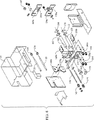
図面のうち図1及び図2に全体を符号10で示された針金結束装置が、米国特許第3,138,904号及び米国特許第3,919,829号に開示された形式のコンベヤ300の側部に隣接して設けられており、かかる米国特許の内容全体を本明細書の一部を形成するものとしてここに引用する。コンベヤ300は例えば、パンの塊125a,125b,125cを連続的に針金結束装置10に搬入し、そしてこれを通過させ、更にこれから搬出させる。コンベヤ300は、当業者に周知であり、その詳細な説明は、以下に詳細に説明するように駆動機構と関連して述べる場合を除けば不要であると考えられる。他の構造及び別の構造でコンベヤを形成してもよいことは理解されるべきである。
【0011】
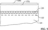
パンの塊125cは、袋結束装置10に向かって移動している状態にあり、袋の首は、袋の首にいたずら防止クロージャを形成するための装置100に隣接して位置決めされる。袋125bは、コンベヤ300及びギャザリングベルトによって、針金状のリボンが袋のすぼめられた首に巻きつけられ、そして捩じられる位置まで動かされた状態にある。パンの塊125aは、結束装置10を通って結束装置から出たばかりの状態にある。図面の図9及び図10を参照すると、装置100は、袋125の側部125x,125yを互いに溶着し、いたずら防止シールストリップ130を形成している。シールストリップ130を袋から取り除いて袋の内容物を取り出すことができるようにミシン目の列132がシールストリップ130に隣接して袋125の首に形成されている。
【0012】
捩じられた針金状リボン115は、袋をミシン目入りストリップ132と袋125aの内容物との間で密閉する。
【0013】
図面の図9及び図10に最もよく示されているように、袋の互いに反対側の側部125x,125yは、シールストリップ130に沿って互いに溶着されており、シールストリップ130に隣接してミシン目の列132が形成されている。いたずら防止シール130,132を袋の首125に形成した後、鮮度を維持すると共に袋の内容物の汚染を防止するために任意の従来型取外し可能なクロージャ、例えば捩り針金状ひも115、袋の首を掴むスロット付きのプラスチック製クリップ又は接着テープを袋の首に取り付けるのがよい。シールストリップ130は、袋をミシン目の列132に沿って引き裂くことにより容易に取り除ける。
【0014】
シールストリップ130が、いたずらされたことが分かるようにする袋125a用クロージャを構成し、袋の内容物に接近するには袋ミシン目の列132に沿って引き裂くことによって必ずシールストリップ130を取り除かなければならないことは明らかである。次に、捩りひも115を取り外すと、袋を開封することができ、そして再び取り付けると袋を再び密閉することができる。
【0015】
いたずら防止クロージャを形成する装置100は、袋の首の両側に係合してミシン目の列132を形成する1対のローラ及び加熱されたガス、例えば空気をミシン目の列132に隣接した袋の首の表面に当てるよう差し向けて袋の首のパネルを互いに溶着し、シールストリップ130を形成するための1対のマニホルドを有している。
【0016】
図面の図3、図4及び図8を参照すると、符号140pは全体として、周囲に設けられた歯142pを備えるローラを示しており、ローラ150pにはローラ140pの歯142pを受け入れる溝152pが形成されている。袋がローラ140pとローラ150pとの間を移動すると、ローラ140pの歯142pは、袋の首に穴をあけ、袋の首にミシン目の列132を形成する。
【0017】
図面のうち図2及び図8に最もよく示されているように、1対のギャザリングベルト41,43が、被動ローラ140,144及びシャフト146に取り付けられた駆動ローラ145の周りに掛かっている。シャフト146の反対側の端部にはプーリ147が取り付けられ、このシャフトは、プーリ147,148の周りに掛けられたベルト25aによって駆動される。プーリ148は、シャフト25に取り付けられ、このシャフト25は、袋の首結束装置10の被動プーリ24及びアイドラープーリ26,27,28の周りに掛けられた上側ギャザリングベルト22を駆動する。
【0018】
ローラ150pの表面には溝152pが形成されており、このローラは、図8に示すようにローラ150,154,155の周りに掛けられた1対のギャザリングベルト51,53によって駆動される。駆動ローラ155は、シャフト156に取り付けられており、このシャフト156の端部にはプーリ157が取り付けられている。駆動ベルト35aが、シャフト35の端部に取り付けられたプーリ158の周りに掛かっており、シャフト35は、袋結束装置10の被動プーリ34及びプーリ36,37,38の周りに掛けられた結束装置10の下側ギャザリングベルト32を駆動する。
【0019】
上側ギャザリングベルト41,43及び下側ギャザリングベルト51,53は、シールストリップ130を形成するようシールされる袋のセグメントの両側に隣接して袋の首を掴むことは注目されるべきである。ローラ140pの歯142pは好ましくは、ギャザリングベルトを41,43相互間の袋の首のセグメントに隣接した状態でこれから間隔を置いて位置する。
【0020】
歯が形成されているローラ140pは、プーリ147,148の周りに掛かっているベルト25aによりギャザリングベルト22と同期関係をなして駆動され、溝152pが形成されているローラ150pは、プーリ157,158の周りに掛かっているベルト35aにより下側ギャザリングベルトと同期関係をなして駆動されることは明らかである。
【0021】
ローラ140,144,145は、取付けプレート149に取り付けられ、ローラ150,154,155は、取付けプレート159に取り付けられている。シャフト146,156の両端は、取付けプレート149a,159aによって支持されている。
【0022】
頂部プレート149bは、ねじによって取付けプレート149,149a相互間に固定された互いに反対側の端部を有し、側部プレート149cは、頂部プレート149bに全体として垂直な状態で取付けプレート149,149a相互間に垂直方向に延びている。
【0023】
上側ヒータ160が、図面の図6及び図7に最もよく示されているようにU字形ボルト162,164によって頂部プレート149bに固定されている。上側ヒータ160の後方端部が、取付けプレート149aに形成された通路160aを貫通して延びている。
【0024】
下側ヒータ170が、取付けプレート159,159aに形成された開口部を貫通しており、このヒータは、U字形ボルト172,174によって垂直方向に延びる取付けプレート159cに隣接して底部取付けプレート159bに固定されている。
【0025】
加熱された空気がヒータ160から上側マニホルド165内へ送り込まれると共に加熱された空気がヒータ170から下側マニホルド175内へ送り込まれる。
【0026】
マニホルド165,175には、好ましくは、列状の空気ジェットを形成する細長いオリフィスが形成され、これら空気ジェットは、マニホルド165,175相互間を移動している袋の首の表面に当たるよう放出される。空気の温度及び風量は、袋のパネルを互いに溶着させてシールストリップ130を形成するのに十分な熱を送るよう選択される。
【0027】
加熱された空気のジェットを放出してこれを袋の表面に当てることにより、加熱された溶封要素で袋の物理的に互いに接触した表面を溶封させることなく、袋のパネルを溶着できることは理解されるべきである。かくして、袋の首に硬化していない濡れたインキ又は熱によって軟らかくなったインキが付いていてもシールストリップ130をこの上に形成することができる。濡れたインキ又は軟らかくなったインキは、マニホルド165,175に移着しない。というのは、マニホルドは、袋の首の表面に物理的に接触しないからである。
【0028】
空気マニホルド165,175は好ましくは、例えば、出口開口部を形成するよう配置された約0.040インチ(約1.016mm)の20個のオリフィスを有し、かかる出口開口部は、空気流を放出して袋の首125の上下でパネル125x,125yに当て、パネル125x,125yを互いに溶着してシールストリップ130を形成するのに十分な温度までパネル125x,125yを加熱する。
【0029】
ヒータ160,170は好ましくは、これを通って流れている空気を電気的に加熱し、この空気は、図面の図2に示されているように、空気供給ライン180から圧力調整器182、フィルタ184及び供給ライン185を通って送られている。空気供給ライン185は好ましくは、ライン187を通ってヒータ160,170に送られる空気の圧力及び風量を制御するための制御弁186を通過している。下側ヒータ170のヒータマウントは、上側ヒータ160のヒータマウントと実質的に鏡像関係にあり、ヒータ160,170は、袋125内のパンの塊に付着している切れ端がローラ140,150相互間のニップ内に落下した場合にローラ140,150を互いに分離できるようにフレームに取り付けられている。ローラ140は、ローラ150に向かって下方にばね押しされているが、必要に応じて上方に回動でき、それにより切れ端又は他の障害物がローラ140,150相互間のニップを通過するようにさせることができる。
【0030】
各ヒータ160,170は好ましくは、電気的発熱要素を備え、この電気的発熱要素は、ヒータ160,170からマニホルド165,175に送られる空気の温度を調節するのに適したサーモスタットを介して接続されている。さらに、ヒータ160,170によって供給される空気の温度を指示し、この温度が所定範囲内に維持されるようにするために熱電対がマニホルド165,175内に設けられている。
【0031】
図11の表に示すように、シールストリップ130を形成するのに必要な空気の温度は、袋125を形成するのに用いられた材料の厚さ及び組成並びに袋の首をマニホルド165,175相互間で移動させるコンベヤ300の速度に応じて様々である。袋の厚さが増大すると、空気マニホルド165,175を通って送られる空気の温度は一般に高くなる。コンベヤの速度が増大すると、空気の温度が上昇してシールストリップ130を形成するための制御された空気の風量及び熱がマニホルド165,175を通って送られる。
【0032】
圧力調整器182を通って供給される空気の圧力は好ましくは、約25psiであり、ヒータ160,170は好ましくは、マニホルド165,175を通って流れる空気を例えば600°F(約315.6℃)の最高温度まで加熱するよう選択される。熱電対は、マニホルド165,175を通って流れる空気の温度の読みをもたらし、ヒータ160,170を通って送られる空気の温度は、シールストリップ130を形成するための所望量の熱を生じさせるよう調節できる。
【0033】
図面の図1及び図2に符号10で全体を示す針金結束装置は、いたずら防止クロージャを形成するための装置と組み合わせた場合を除き、それ自体では請求の範囲に記載された本発明の要部をなさない。針金結束装置は主要構成要素として、米国特許第5,483,134号に示すように上側及び下側ギャザリングベルト22,32を有し、上側ギャザリングベルト22は、シャフト25に設けられたプーリによって駆動され、下側ギャザリングベルト32は、シャフト35に設けられたプーリによって駆動される。上述したように、いたずら防止クロージャを形成するための装置内におけるローラの動作は、ベルト25a,35aを介してシャフト25,35の回転と同期する。
【0034】
上側及び下側ギャザリングベルト22,32は、袋125を、針組立体、捩り装置のフック組立体、及び針金状のひもを袋120のすぼめられた首の周りに巻きつけるためのホルダ−せん断組立体(図示せず)の近くの位置に至る経路に沿って移動させる。
【0035】
例えば「水平」、「垂直」、「上」及び「下」という用語は、図面と関連して用いた場合、一般に図示の実施形態では部品の向きを示しているが、使用にあたって、記載されたままの向きである必要はない。
【0036】
第2の実施形態
いたずら防止クロージャを袋の首に形成するための装置の第2の実施形態が、図12〜図19に示されている。この装置の部品は、幾つかの部品及び動作態様が入れ替えられている点を除き、第1の実施形態と実質的に同一である。
【0037】
図16及び図18を参照すると、ヒータハウジング200が、端壁相互間に設けられていて、ヒータハウジング200内に高温領域201、中間領域203及び低温領域205を形成するための仕切り壁202,204を有している。低温領域205内に設けられていて、空気をヒータ260,270に送るためのブロワ230によって中間領域に引き込まれた空気を清浄にするための空気フィルタが、中間領域203内に設けられている。以下に詳細に説明するように、ヒータハウジング200から使用済みの空気を排出するための排気ファン208が高温領域201内に設けられている。
【0038】
図面の図12及び図18を参照すると、機外上側ギャザリングベルト241及び機内上側ギャザリングベルト243が、上側シャーシ222に取り付けられ、機外下側ギャザリングベルト251及び機内下側ギャザリングベルト253が、下側シャーシ225に取り付けられている。
【0039】
ベルト251,253を支持している下側シャーシ225は、もし容量センサ215(図14に最もよく示されている)が切れ端又は他の障害物が袋の首の中に落下したことを検出すると、図12に示す位置から図13に示す位置に動くことができる。切れ端又は他の障害物を取り除いた後、システムをリセットすると、下側シャーシ225は図12に示す位置に戻る。
【0040】
機外上側ギャザリングベルト241は、外側タイミングベルトプーリ240,244,245,246の周りに掛かっている。機内上側ギャザリングベルト243は、プーリ240a,244a,245a,246aの周りに掛かっている。プーリ240,240aは、シャフト240bに取り付けられ、プーリ244,244aは、シャフト244bに取り付けられ、プーリ245,245aは、シャフト245bに取り付けられ、プーリ246,246aは、シャフト246bに取り付けられている。
【0041】
図18に最もよく示されているように、上側シャーシ222は、端壁相互間にボルト止め又は別の方法で固定されている互いに間隔を置いたプレート221,223によって形成されている。図示の実施形態では、上側シャーシは動くことができず、シャフト240b〜246bは、互いに間隔を置いたプレート221,223内に設けられている軸受227で支持されている。
【0042】
機外下側ギャザリングベルト251は、外側プーリ250,254,255,256の周りに掛かっている。機内下側ギャザリングベルト253は、プーリ250a,254a,255a,256aの周りに掛かっている。プーリ250,250aは、シャフト250bに取り付けられ、プーリ254,254aは、シャフト254bに取り付けられ、プーリ255,255aは、シャフト255bに取り付けられ、プーリ256,256aは、シャフト256bに取り付けられている。下側シャーシ225は、端壁に対して垂直方向に動く滑り板又はスライドプレート相互間にボルト止め又は他の方法で固定されている互いに間隔を置いたプレート224,226によって形成されている。図示の実施形態では、下側シャーシは動くことができ、シャフト250b〜256bは、互いに間隔を置いたプレート224,226内に設けられている軸受228で支持されている。以下に詳細に説明するように、軸受227,228は、タイミングプーリ240〜256b及びマニホルド265,275から内方へ、排気ファン208によってヒータハウジング200内の高温領域201に垂直方向に引き込まれた使用済み空気により軸受227,228の過度の加熱を防止するのに十分な距離を置いて位置している。
【0043】
穴あけホイール220は、これに設けられたハブの周りに掛かっているベルト240xによって駆動されると共にシャフト255bに設けられたプーリ(図示せず)によって駆動される。
【0044】
図14に示す空気ノズル209が、可撓管209aに連結され、この可撓管を通って空気が空気圧縮機(図示せず)又は他の適当な圧縮空気源から送り出されてジェットが形成され、このジェットは袋の首を平らにしてこれを、コンベヤの縁部の上方に位置決めされた第1の対をなすブラシ210,214と、コンベヤの縁部の下に位置決めされた第2の対をなすブラシ212,216との間のニップに入るよう位置決めする。空気ジェットは、袋125aの側部125xを袋125aの側部125yへ押しやる。
【0045】
パンの塊の切れ端が袋の首の中に落下するとこのことを検出する容量センサ215が、空気ノズル209とブラシ210〜216との間に位置決めされている。切れ端又は他の障害物が袋の首の中に落下すると、センサは、コンベヤを停止させ、密封装置を図13、図15及び図17に示すように非動作位置に作動させる信号を出す。センサ215は、センサーに隣接したところでの所定範囲から外れる質量の変化を検出するキャパシタ型センサである。
【0046】
袋の首に障害物が存在していなければ、袋の首は、上側及び下側の対をなすブラシの間を動く。図14に最もよく示されている第1の上側ブラシ210及び下側ブラシ212は、剛毛を有していて、互いに逆方向に回転し、したがって上側ブラシ210の下面及び下側ブラシ212の上面は同一方向に動くと共に袋の首に係合し、それにより袋をコンベヤの横方向に引っ張り、ついには袋の内容物が案内バーに係合するようになり、これら案内バーは、袋の内容物が動いて案内バーに係合すると袋の横方向の動きを止める。第1の上側及び下側ブラシ210,212のブラシ掛け作用により、袋はその内容物の周りにピンと引っ張られる。
【0047】
第2の上側及び下側ブラシ214,216は、互いに間隔を置いた列をなす斜めの剛毛を有し、これら斜めの剛毛は、袋の首の前縁を後縁から遠ざけて袋の首を平らにし、袋をシールする前に袋から空気を排気するために第1の上側及び下側ブラシ210,212の剛毛よりも僅かに長い。斜めに配置された剛毛は好ましくは、第1の上側及び下側ブラシ210,212の剛毛よりも直径が約1/8インチ(3.175mm)長い。
【0048】
第1の対をなす上側及び下側ブラシ210,212は、袋を製品の周りに引っ張り、これ対し第2の対をなす上側及び下側ブラシ214,216は袋の首を平らにし、袋内から空気を排出し、袋の首の前縁を上側ベルト241,243を下側ベルト251,253との間に位置決めすることは明らかである。袋の首をコンベヤの横方向に移動させる第1の組をなすブラシ210,212は、袋の首を弾性的に保持し、第2の対をなす上側及び下側ブラシ214,216とギャザリングベルトによって得られるコンベヤの長さ方向における袋の首の動作に抵抗する傾向がある。かくして、袋の首の前縁は、ギャザリングベルトによって掴まれ、後縁はブラシの間から引っ張られて袋がギャザリングベルトと、水平方向に間隔を置いて位置したベルト241,243相互間の空間を跨ぎ、実質的に平らな袋の首の部分との間に引っ張られながら袋の首が伸ばされるようになる。
【0049】
図14及び図15に示すように、穴あけ組立体は、袋の首の下方に位置し、周囲に歯221がぐるりと間隔を置いて設けられた穴あけホイール220と、袋の首の上方に位置し、スロット217が設けられたアンビル218とで構成されている。袋の首は、ベルト241,243の下面とベルト251,253の上面との間でピンと引っ張られた状態に保持されている。
【0050】
穴あけホイール220の各歯221は、ベルト相互間を跨いでいる袋の首の部分に所定の切れ目又は細長いスロットを入れるよう形作られている。所定長さの領域221aが、切断されていない互いに間隔を置いた領域を袋の首に残すよう穴あけホイール220の隣り合う歯221相互間に形成されている。穴あけホイール220が、袋を移動させているベルトと同期関係をなして1対のベルトによって駆動され、穴あけホイールに隣接して動いている袋がどれも実質的に同一であるようにする。
【0051】
穴あけホイール220は、軸受を介して下側ベルトシャーシ225に固定された短軸に取り付けられている。穴あけホイールの歯は、上側シャーシ222によって支持されたアンビルの下面のスロット内へ延び、袋は、穴あけホイールの互いに反対側の側部に隣接した平らな面によって支持されるようになっている。
【0052】
図面の図12を参照すると、上述したように、上側ギャザリングベルト241,243は上側シャーシ222に取り付けられ、下側ギャザリングベルト251,253は下側シャーシ225に取り付けられている。ベルト251,253を支持している下側シャーシ225は、もし容量センサ215が袋の首の中に落下した切れ端を検出すると、図12に示す位置から図13に示す位置に動くことができる。切れ端又は他の障害物を取り除いた後、システムをリセットすると、下側シャーシ225は図12に示す位置に戻る。穴あけホイール225は、ベルト240xによって駆動され、このベルトは、穴あけホイールに設けられたハブの周りかけられていて、シャフト255bに取り付けられたプーリ(図示せず)によって駆動される。
【0053】
図面の図18及び図19を参照すると、プーリ240,245aを備えたシャフト240b及びプーリ255,255aを備えたシャフト255bが、図面の図19に示すようにプーリの周りに掛けられたベルト320によって駆動される。シャフト245bは、アイドラーシャフトであり、その後端部にはプーリは設けられていない。
【0054】
タイミングベルトプーリ254,254aを駆動するためのプーリ304がシャフト255bに取り付けられている。タイミングベルトプーリ350,350aを駆動するためのプーリ305がシャフト256bに取り付けられている。アイドラープーリ306は、下側シャーシ225によって支持された短軸に取り付けられている。
【0055】
ベルト241,243,251,253をコンベヤ300の表面速度に等しい速度で駆動するための直流駆動モータ315が、適当な駆動手段、例えば結束装置からの出力又はコンベヤに設けられたデコーダモジュールに電気的に接続されている。モータ315は、駆動シャフトに取り付けられていて、ベルト320を駆動するための駆動プーリ310を有し、ベルト320は、アイドラープーリ309、上側ベルト341,343を駆動するプーリ302、駆動プーリ304、アイドラープーリ305、シャフト246b,256bを駆動する駆動プーリ306、及びプーリ308の周りに掛かっている。
【0056】
上側ベルト241,243を支持した上側シャーシ222は動かない。ベルト251,253を支持した下側シャーシ225は、図19に示すように垂直方向に動かすことができ、かくして下側シャーシ225をベルトの上側の対及び下側の対を互いに分離するためのオフ位置に移動させることができる。図19に参照すると、シャーシ225が下方に移動しても、駆動ベルト320の長さは変わらないことは明らかである。というのは、シャーシ225が垂直方向に動くと、プーリ304,305,306は回転してベルト320に沿って前進するからである。かくして、ベルトの張力は変わらない。
【0057】
図面の図16を参照すると、3段ブロワ230が、多量の加圧空気を電気ヒータ260,270に送るようになっている。ヒータ260,270は好ましくは、空気を発熱要素上に循環させるよう構成されており、この発熱要素は、空気を制御された温度に加熱し、この空気を分流弁262,272を介して、それぞれ上側マニホルド265及び下側マニホルド275に送るようになっている。各マニホルド265,275は、細長いスロットを有し、この細長いスロットを通して,加熱された空気が送り出され、機外ベルト241,251と機内ベルト243,253との間の空間を跨ぐ袋の首の平らになった表面に当たるようになっている。袋の首が上側マニホルド265と下側マニホルド275との間を移動する前に穴あけホイール220によってミシン目の列132が袋の首に既に形成されていることは理解されるべきである。これにより、袋は、冷却されながら穴あけされ、この穴あけは、穴あけホイール220の歯221が袋の首に係合したときに袋が引き伸ばされて変形する傾向のある温度まで加熱される前に行われる。高速で流れる加熱空気は、袋の首の上面及び下面に当たり、上面と下面を互いに溶着させるようになっている。空気はベルト相互間を跨ぐ袋の部分に当たり、溶融状態のプラスチック又は高温空気によって軟らかくなったインキが、袋の首の冷却以前にベルト又は任意他の機構に移着することはないことは理解されるべきである。
【0058】
上側分流弁262及び下側分流弁272は、下側シャーシ225を非作動位置に動作させると、空気シリンダによって図16に示す位置から図17に示す位置まで回転するばね押しパドルを備えている。これにより、加熱された空気は、下側シャーシ225が下方に動かされるとマニホルド265,275に隣接して位置する場合のある袋の首から排気ポートを通って遠くへ逸らす。空気を図17に示すように逸らすことによっても、空気はベルトの付近から遠ざかるように差し向けられ、それによりベルトが過熱しないようになる。
【0059】
図16に最もよく示されているように、3段ブロワ230は、仕切り壁204を貫通して設けられていて、空気を空気フィルタ206を通して中間領域203から引き込むための吸気ライン230aを有している。空気は、ブロワ232によってライン260a,270aを通ってヒータ260,270に送り込まれる。空気は好ましくは、複数の経路に沿ってヒータ260,270から分流弁262,272に送られる。ばね押しパドルが図16に示す位置にあるとき、空気は、マニホルド265,275を通って送られて、機外ベルトと機外ベルトを跨いでいる袋の首の上面及び下面に当たる。レバー262a,272aを回すと、ばね押しパドルは、図16に示す位置から図17図に示す位置まで動いて、空気を排気ポート262e,272eを通って高温領域201に送り込み、この空気は、高温領域201の上端部及び下端部に設けられた排気ファン208によって高温領域201から排気される。
【0060】
マニホルド265,275のすぐ近くに配置された分流弁262,272は、空気を逸らしてこれを迅速にマニホルドから排気ポートへ、そしてマニホルドに戻すことができる。加熱空気は、分流弁265,275を通って連続的に流れているので、上述の機構は、温度が許容レベルから逸脱せず、パドルを或る一つの位置から別の位置に移動させてもウォームアップ期間を必要としない。
【0061】
中間領域203が高温領域201と低温領域205との間に設けられているので、高温領域201は電気制御装置及びブロワ230が設けられている低温領域205から効果的に隔離される。さらに、仕切り壁202に隣接したフィルタ206中に空気を引き込むことにより、ブロワ230内に引き込まれる空気が予熱される。
【0062】
3段ブロワ230は、多量の比較的高い圧力の空気をヒータ及びマニホルド265,275中へ送り込むよう構成されている。発熱要素上に空気をヒータ260,270を通って連続的に安定供給することにより、空気の温度及び風量は、過度の熱が送られないようにしながら袋の首がマニホルド265,275の間を通る時に袋の首をシールするようにするパラメータ内に維持される。ヒータ260,270内の発熱要素は、種々の材料で作られたり異なる厚さのプラスチックで作られている袋に適合させるために、サーモスタットの作用で制御される。
【0063】
注目されるべき重要なこととして、ブラシ210,212,214,216は、袋の首を平らにし、過剰の空気を袋の内側から排気し、ミシン目の列132及びシールストリップ130を袋の首に終始一貫して形成できるように構成されている。
【0064】
ベルトは好ましくは、ベルトの縁部がベルトを支持するタイミングベルトプーリ240〜256aのフランジを越えて延びることができるようにアンダーカットされ又は短くされた歯241tを有するタイミングベルトである。これにより、袋の首は、ベルト及びタイミングベルトプーリのフランジに巻きついたり、これらの間に挟まれないようになる。軟質で柔軟性のある材料の層241xを各ベルト本体241yの外面上に加硫すると、タイミングベルトプーリと係合する比較的硬くて耐久性のある表面が得られるようになると共に袋の首に係合する比較的軟質で柔軟性のある表面が各ベルト上に得られるようになる。これにより、ベルトは袋を掴み、袋の首を穴あけホイール220に隣接すると共に袋の首がシールストリップ130の形成される上側マニホルド265と下側マニホルド275との間に動かされているときの滑りを最小限に抑える。
【0065】
テフロン強化スライダプレート300sが、上側シャーシ222及び下側シャーシ225にボルト止め又は他の方法で固定された取付けプレート301に固定されている。プーリ344,345の間及びプーリ354,355の間の空間を跨ぐベルトはスライドプレート300xに係合し、それにより、ベルトの撓みが防止され、それによりベルトは上側マニホルド265及び下側マニホルド275の互いに反対側の側部に隣接している袋の首の互いに間隔を置いた部分をしっかりと掴むようになる。
【0066】
図面の図12に最もよく示されているように、レバー262a,272aが分流弁262,272からは外方に延びており、これらレバーは、シリンダのロッドに設けられていて、分流弁中のばね押しパドルを図16に示す位置から図17に示す位置に動かすターンバックルと係合している。
【0067】
いたずら防止シールを形成するための方法及び装置の好ましい実施形態を開示したが、本発明の基本構想から逸脱しないで、他の実施形態を想到できることは明らかである。
【図面の簡単な説明】
本発明の好ましい実施例の図面をここに添付し、これにより本発明を完全に理解できるであろう。
【図1】 いたずら防止シールを形成するための装置を備えた袋の首結束装置械の正面を示す斜視図である。
【図2】 袋ひも結束装置及びいたずら防止シールを形成するための装置の背面図である。
【図3】 袋の首のギャザリングベルト及びミシン目を形成するための歯付きローラを示す部分拡大斜視図である。
【図4】 袋を穴あけするローラを示す部分拡大図である。
【図5】 いたずら防止シールを形成するための装置の背面及び側面を示す斜視図である。
【図6】 いたずら防止シールを形成するための装置の斜視図であり、その構造の詳細を明らかに図示するためにカバーを取り除いてある。
【図7】 ヒータ、空気マニホルド、いたずら防止シールを形成するための穴あけ用ローラの関係を示す拡大図である。
【図8】いたずら防止シールを形成するための装置の部品を示す分解斜視図である。
【図9】 密閉したストリップ及び袋の首に形成されたミシン目列を示す部分概略図である。
【図10】シールストリップ、ミシン目列、取り外し可能な止め体の関係を示す袋の斜視図である。
【図11】 コンベヤ速度、袋の厚み、温度の関係の例を示す表である。
【図12】 作動位置にあるベルト組立体の斜視図である。
【図13】 図12と同様の図であり、下方ベルト架台が下方位置にある。
【図14】 ベルトが図12に示す位置にある概略図である。
【図15】 ベルト組立体が図13に示す位置にある概略図である。
【図16】 ヒータ及びマニホルド組立体の概略図であり、ベルト組立体が図12、図14の位置にある。
【図17】 図16と同様の概略図であり、ベルト組立体が図13、図15の位置にある。
【図18】 概略側面図である。
【図19】 図18の19−19線に実質的に沿って概略図である。
図面中の同じ要素を示すのに参照符号を使用する。[0001]
〔Technical field〕
The present invention relates to an anti-tamper closure attachment accessory for a device for wrapping a ribbon around a bag's constricted neck and twisting the ribbon to close and seal the neck of the flexible bag.
[Background Technology]
U.S. Pat. No. 3,138,904 (Title of Invention: Method and Apparatus for Tying Package and Wrapping Material), U.S. Pat. No. 3,059,670 (Title of Invention: Wire Twisting Device), U.S. Pat. No. 3,919,829 (Packaging and Wrapping Material) A device for tying straps), U.S. Pat. No. 4,856,258 (Title of wire binding device) and U.S. Pat. No. 5,483,134 (Title of ribbon sensing device for bag binding device) Disclosed is an apparatus used to close a plastic bag by attaching a wire-like ribbon around it and twisting it.
[0002]
Bag binding devices of the type disclosed in the aforementioned patents are available from Buford Corporation, Maysvill, Oklahoma. This bundling device is typically made to accept packages such as loaf bread at a rate of making more than 100 packages per minute, for example at a rate of about 108 feet / minute.
[0003]
A plastic bag containing bread products, paper pieces and ice can be easily opened to access the contents of the bag by removing the twisted ribbon around the neck of the bag. The bag can be resealed by hand by placing the ribbon again around the bag neck and twisting it.
[0004]
U.S. Pat. No. 5,600,938 discloses an apparatus for sealing a plurality of spaced points across a flattened open end of a plastic bag containing contents. The bag is moved along the conveyor through a sealing mechanism that welds a plurality of spaced locations across the open end of the bag. In one embodiment, the sealing mechanism includes a plurality of heated pins that penetrate the two layers at the open end of the bag while substantially flattening the end of the bag. These pins then move with the bag in synchronism with the conveyor while welding. In another embodiment, the sealing is performed using a wheel with a heated pin around it, the wheel rotating so that its tangential speed is synchronized with the conveyor, one after the other, at spaced weld locations. Is formed across the generally flattened open end of the bag. This device allows multiple bags to be carefully sealed to show evidence that they have been tampered with by breaking the seal while allowing the bag to be opened without tearing or breaking the bag. Seal the separated parts.
[0005]
U.S. Pat. No. 5,741,075 describes a package having a flexible plastic bag and a label. The bag has a closed end that can be opened to create an opening for accessing the contents of the package. The closed end of the package is first sealed in a sealing area, which is provided with a line of perforations that form an opening and can be closed again by a label. This label is disclosed as having two adhesive areas on one side separated by a non-adhesive area extending across substantially the entire width of the label. The two adhesive areas are adapted to adhere to the package on each side of the perforation line. Satisfactory methods and apparatus are not disclosed that form a seal and a single perforation to provide a tear strip that can be seen to be initially tampered with.
[0006]
Thus, a system has not yet been developed to form a re-closeable tamper-proof seal that can be economically employed to safely protect the contents of the bag before it is opened by the end consumer. .
[Summary of the Invention]
The apparatus disclosed herein is used to form an anti-tamper seal on a plastic bag. Here, both sides of the bag are welded to form a seal adjacent to a row of perforations formed in the bag so that the seal can be torn from the bag. After the seal and perforated strip are formed in the bag, the bag neck is shrunk and tied by twisting the wire ribbon around the bag neck.
[0007]
The apparatus for forming the tamper-proof seal is preferably mounted, for example, on a bag binding apparatus of the type disclosed in US Pat. No. 5,483,134, the entire disclosure of which is incorporated herein by reference. Cite here as a thing. The gathering belt is attached to a pulley synchronized with the gathering belt of the bag neck binding device.
[0008]
The bag neck is flattened near the gathering belt, and the flattened bag neck moves adjacent to a roller with protrusions that form a row of perforations in the bag neck. The bag passes between a pair of manifolds that apply a stream of heated air against the upper and lower surfaces of the bag neck to seal the bag. The manifold does not contact the bag surface so that the neck of the bag can be sealed even if the printing ink on the surface of the bag is not dry or if heat softens the printing ink.
[0009]
When the seal and perforation line are formed in the bag, the bag neck passes through the binding device, where the bag neck is shrunk, bound, and discharged from the binding device in a conventional manner. Is done.
[0010]
Instead of a twisted wire string around a constricted neck, other closure means such as a plastic wireless twist string or a plastic clip with a slot or adhesive tape may be attached to the constricted neck of the bag . This closure seals the bag between the perforation and the contents to prevent contamination and maintain the freshness of the contents of the bag.
DESCRIPTION OF PREFERRED EMBODIMENTS
A wire binding device, generally designated 10 in FIGS. 1 and 2 of the drawings, is disclosed in US Pat. No. 3,138,904 and US Pat. No. 3,919,829. The entire contents of such U.S. Patents are hereby incorporated by reference as being part of this specification. The
[0011]
The
[0012]
The
[0013]
As best shown in FIGS. 9 and 10 of the drawings, the
[0014]
The
[0015]
The
[0016]
Referring to FIGS. 3, 4, and 8 of the drawings,
[0017]
As best shown in FIGS. 2 and 8 of the drawings, a pair of gathering
[0018]
A groove 152p is formed on the surface of the
[0019]
It should be noted that the
[0020]
The
[0021]
The
[0022]
The
[0023]
[0024]
A
[0025]
Heated air is fed from the
[0026]
[0027]
By releasing a jet of heated air and applying it to the bag surface, it is possible to weld the panel of the bag without having the heated sealing element seal the physically contacting surfaces of the bag. Should be understood. Thus, the
[0028]
The air manifolds 165, 175 preferably have 20 orifices, for example, of about 0.040 inches (about 1.016 mm) arranged to form an outlet opening, which outlet opening allows air flow.
[0029]
The
[0030]
Each
[0031]
As shown in the table of FIG. 11, the temperature of the air required to form the
[0032]
The pressure of the air supplied through the
[0033]
The wire binding device, generally designated by
[0034]
The upper and lower gathering belts 22, 32 are holder-shear pairs for wrapping the
[0035]
For example, the terms “horizontal”, “vertical”, “upper”, and “lower”, when used in conjunction with the drawings, generally indicate the orientation of the component in the illustrated embodiment, but are described in use. It doesn't have to be in the same direction.
[0036]
Second embodiment
A second embodiment of an apparatus for forming an anti-tamper closure on the neck of a bag is shown in FIGS. The components of this apparatus are substantially the same as those of the first embodiment except that some components and operation modes are replaced.
[0037]
Referring to FIGS. 16 and 18, a
[0038]
Referring to FIGS. 12 and 18 of the drawings, an outboard
[0039]
The
[0040]
The
[0041]
As best shown in FIG. 18, the
[0042]
The
[0043]
The
[0044]
An air nozzle 209 shown in FIG. 14 is connected to a flexible tube 209a through which air is pumped from an air compressor (not shown) or other suitable compressed air source to form a jet. The jet flattens the bag neck into a first pair of
[0045]
A
[0046]
If there are no obstacles in the bag neck, the bag neck moves between the upper and lower pair of brushes. The first
[0047]
The second upper and
[0048]
The first pair of upper and
[0049]
As shown in FIGS. 14 and 15, the drilling assembly is located below the neck of the bag, with a
[0050]
Each
[0051]
The
[0052]
Referring to FIG. 12 of the drawings, as described above, the
[0053]
Referring to FIGS. 18 and 19 of the drawings, a shaft 240b with
[0054]
A
[0055]
A DC drive motor 315 for driving the
[0056]
The
[0057]
Referring to FIG. 16 of the drawings, a three-
[0058]
The
[0059]
As best shown in FIG. 16, the three-
[0060]
The
[0061]
Since the
[0062]
The three-
[0063]
It is important to note that the
[0064]
The belt is preferably a timing belt having teeth 241t that are undercut or shortened so that the belt edge can extend beyond the flanges of the timing belt pulleys 240-256a that support the belt. As a result, the neck of the bag is prevented from being wrapped around or sandwiched between the belt and the flange of the timing belt pulley. Vulcanizing a layer of soft and
[0065]
A Teflon reinforced slider plate 300s is secured to a mounting
[0066]
As best shown in FIG. 12 of the drawings, levers 262a and 272a extend outwardly from the
[0067]
Although a preferred embodiment of a method and apparatus for forming a tamper-proof seal has been disclosed, it is clear that other embodiments can be envisaged without departing from the basic concept of the invention.
[Brief description of the drawings]
The drawings of the preferred embodiment of the present invention will now be attached, so that the invention can be fully understood.
FIG. 1 is a perspective view showing the front of a bag neck tying device with a device for forming a tamper-proof seal.
FIG. 2 is a rear view of a bag string binding device and a device for forming a tamper-proof seal.
FIG. 3 is a partially enlarged perspective view showing a toothed roller for forming a gathering belt and a perforation in a bag neck.
FIG. 4 is a partially enlarged view showing a roller for punching a bag.
FIG. 5 is a perspective view showing the back and side of an apparatus for forming a tamper-proof seal.
FIG. 6 is a perspective view of an apparatus for forming a tamper-proof seal, with the cover removed to clearly illustrate the details of the structure.
FIG. 7 is an enlarged view showing a relationship among a heater, an air manifold, and a drilling roller for forming a tamper-proof seal.
FIG. 8 is an exploded perspective view showing parts of an apparatus for forming a tamper-proof seal.
FIG. 9 is a partial schematic view showing a sealed strip and a perforation formed on the neck of the bag.
FIG. 10 is a perspective view of a bag showing a relationship between a seal strip, a perforation row, and a removable stopper.
FIG. 11 is a table showing an example of the relationship between conveyor speed, bag thickness, and temperature.
FIG. 12 is a perspective view of the belt assembly in the operating position.
FIG. 13 is a view similar to FIG. 12, with the lower belt mount in the lower position.
14 is a schematic view with the belt in the position shown in FIG. 12;
15 is a schematic view of the belt assembly in the position shown in FIG.
FIG. 16 is a schematic view of a heater and manifold assembly, with the belt assembly in the position of FIGS.
FIG. 17 is a schematic view similar to FIG. 16, with the belt assembly in the position of FIGS. 13 and 15;
FIG. 18 is a schematic side view.
FIG. 19 is a schematic view substantially along the line 19-19 in FIG. 18;
Reference numerals are used to denote the same elements in the drawings.
Claims (9)
前記袋の開口端に隣接した前記袋の首の一部を平らにする工程と、
前記平らになった部分の一部分を、一対の上側ベルト(41,43)と一対の下側ベルト(51,53)との間に跨るように配置する工程とを有し、
前記袋の首の部分が、前記上側の一対のベルトと前記下側の一対のベルトとの間の空間に跨るように、前記一対の上側ベルト(41,43)の一方(41)及び前記一対の下側ベルト(51,53)の一方(51)が前記袋の首の第一の部分の上面及び下面にそれぞれ係合し、かつ、前記一対の上側ベルトの他方(43)及び前記一対の下側ベルトの他方(53)が、前記袋の首の前記第一の部分から離間した第二の部分の上面及び下面にそれぞれ係合するように、前記一対の上側ベルト及び前記一対の下側ベルトは、それぞれ水平方向に離間され、
前記方法は、また、前記平らになった部分の一部分を、前記上側の一対のベルトと前記下側の一対のベルトの間を跨ぐように配置する工程と、
前記袋の首にミシン目の列を形成する工程と、
前記袋のパネルを溶着してシールストリップを形成するために、加熱された空気ジェットを、前記上側の一対のベルトと前記下側の一対のベルトの間を跨ぐ前記袋の平らになった部分の一部分に係合するように差し向ける工程とを有し、
前記シールストリップは、前記袋から前記シールストリップを除去するのを容易にするように、前記袋の首のミシン目の列から離間され、
前記袋が冷却されながら、かつ、ミシン目が形成される際に前記袋が引き延ばされて変形する傾向がある温度まで前記袋が加熱される前に、前記袋が穴あけされることを保証するために、前記袋の首の前記ミシン目の列は、前記加熱された空気ジェットが前記袋に係合する前に形成され、
前記袋の首が冷却される前に、溶融状態のプラスチック又は高温空気によって柔らかくなったインキが前記上側の一対のベルトと前記下側の一対のベルト又はいかなる他の機構にも移着しないように、前記空気は、前記上側の一対のベルトと前記下側の一対のベルトの間に跨っている前記袋の平らになった部分に当たり、
前記方法は、また、前記上側の一対のベルト及び前記下側の一対のベルトの近くに障害物が位置するときに、加熱された空気ジェットを前記袋の前記一部分から逸らし、かつ、前記上側の一対のベルト及び前記下側の一対のベルトから逸らす工程と、
前記シール部分と前記製品との間の前記袋の平らになった部分をすぼめる工程と、
前記首に再使用可能なクロージャ(115)を取り付ける工程とを有する方法。A method of forming a seal so that a plastic bag containing a loaf of bread can be seen tampered with,
Flattening a portion of the neck of the bag adjacent to the open end of the bag;
Arranging a part of the flattened portion so as to straddle between the pair of upper belts (41, 43) and the pair of lower belts (51, 53),
Neck portion of the bag, so as to straddle the space between the pair of belts of the lower pair of belts of the upper, one (41) and the pair of the pair of upper belts (41, 43) One of the lower belts (51, 53) (51) engages with an upper surface and a lower surface of the first portion of the neck of the bag, respectively, and the other of the pair of upper belts (43) and the pair of The pair of upper belts and the pair of lower sides so that the other of the lower belts (53) engages the upper and lower surfaces of the second part spaced from the first part of the neck of the bag, respectively. The belts are spaced apart horizontally,
The method also includes disposing a portion of the flattened portion so as to straddle between the upper pair of belts and the lower pair of belts ;
Forming a row of perforations in the neck of the bag;
In order to weld the bag panel to form a seal strip, a heated air jet is applied to the flat portion of the bag straddling between the upper pair of belts and the lower pair of belts . Directing to engage a portion,
The seal strip is spaced from a row of perforations in the neck of the bag to facilitate removal of the seal strip from the bag;
Ensures that the bag is pierced as it cools and before the bag is heated to a temperature where the bag tends to stretch and deform when the perforation is formed In order to do so, the perforation row of the neck of the bag is formed before the heated air jet engages the bag,
Before the neck of the bag is cooled, molten plastic or ink softened by hot air will not transfer to the upper pair of belts and the lower pair of belts or any other mechanism The air hits the flat part of the bag straddling between the pair of upper belts and the pair of lower belts ,
The method also includes deflecting a heated air jet from the portion of the bag when an obstruction is located near the upper pair of belts and the lower pair of belts, and the upper pair of belts. Deviating from the pair of belts and the pair of lower belts;
Squeezing the flattened portion of the bag between the seal portion and the product;
Attaching a reusable closure (115) to the neck.
前記袋の開口端に隣接した前記袋の首の一部を平らにする工程と、
前記平らになった部分の一部分を、上側の一対のベルトと下側の一対のベルトの間に跨るように配置する工程と、を有し、
前記上側の一対のベルトと前記下側の一対のベルトは、水平方向に離間し、
前記方法は、また、前記袋の首にミシン目の列を形成する工程と、
前記袋の前記内容物が利用できないようにシール部分を形成するために、前記袋の首を形成する材料を結合するのに十分な温度まで、前記上側の一対のベルトと前記下側の一対のベルトの間の空間に跨る前記袋の首の平らになった部分を加熱する工程と、を有し、
前記袋の首の前記ミシン目の列は、前記袋の首の平らになった部分が加熱される前に形成され、
前記方法は、また、前記シール部分と前記パンの塊との間の前記袋の首の平らになった部分をすぼめる工程と、
前記袋の首に再使用可能なクロージャを取り付ける工程とを有し、
前記袋の首の平らになった部分を加熱する工程は、
315°F〜600°F(157.2〜315.6℃)の温度まで加熱された空気を送り出して、前記袋の表面に当てる工程と、
前記上側の一対のベルトと前記下側の一対のベルトを使用して、前記空気流が当たる前記袋の前記シール部分の両側に隣接した前記袋の部分を掴む工程とを有し、
前記袋の前記首が冷却される前に、溶融状態のプラスチック又は高温空気によって柔らかくなったインキが前記上側の一対のベルト及び前記下側の一対のベルトに移着しないように、前記空気は、前記上側の一対のベルトと前記下側の一対のベルトの間に跨っている前記袋の首の平らになった部分に当たり、
前記袋の首の平らになった部分を加熱する工程は、また、加熱空気の流れを中断することなく、送り出された加熱空気を、前記上側の一対のベルト及び前記下側の一対のベルトから逸らす工程を有する、方法。Both sides of a plastic bag having a neck having ink softened by heat on the neck of the bag and welded together to make available the contents of the bag containing a loaf of bread A method of forming a seal that allows a bag having a face to be seen to have been tampered with,
Flattening a portion of the neck of the bag adjacent to the open end of the bag;
Arranging a part of the flattened portion so as to straddle between the upper pair of belts and the lower pair of belts ,
The pair of upper belts and the pair of lower belts are separated in a horizontal direction,
The method also includes forming a row of perforations in the neck of the bag;
The pair of upper belts and the pair of lower pairs up to a temperature sufficient to join the material forming the neck of the bag to form a sealed portion so that the contents of the bag are not available . Heating the flattened portion of the bag neck across the space between the belts ;
The perforation row of the bag neck is formed before the flattened portion of the bag neck is heated;
The method also includes squeezing a flattened portion of the neck of the bag between the seal portion and the loaf of bread;
Attaching a reusable closure to the neck of the bag,
Heating the flattened portion of the neck of the bag,
315 ° F~600 ° F turned out air heated to a temperature of (157.2-315.6 ° C.), the steps of applying to the surface of the bag,
Using the upper pair of belts and the lower pair of belts, and gripping portions of the bag adjacent to both sides of the seal portion of the bag against which the air flow strikes,
Before the neck of the bag is cooled, the air is not transferred to the upper pair of belts and the lower pair of belts so that the melted plastic or ink softened by hot air does not transfer Hit the flat part of the neck of the bag straddling between the pair of upper belts and the pair of lower belts ,
The step of heating the flattened portion of the bag neck also allows the heated air to be sent from the pair of upper belts and the pair of lower belts without interrupting the flow of heated air. A method comprising a step of deflecting .
前記袋の中の製品と前記袋の首の開口端との間に前記袋の首を横切ってミシン目の列(132)を形成する工程と、
一対の上側ベルト(41,43)と一対の下側ベルト(51,53)との間で、前記ミシン目の列の両側面に隣接した離間した位置で前記袋を掴む工程と、を有し、
前記袋の首の部分が、前記上側の一対のベルト(41,43)と前記下側の一対のベルト(51,53)との間の空間に跨るように、前記上側ベルトの一方(41)及び前記下側ベルトの一方(51)が前記袋の首の第一の部分の上面及び下面にそれぞれ係合し、かつ、前記上側ベルトの他方(43)及び前記下側ベルトの他方(53)が、前記袋の首の前記第一の部分から離間した第二の部分の上面及び下面にそれぞれ係合するように、前記一対の上側ベルト(41,43)及び前記一対の下側ベルト(51,53)は、それぞれ水平方向に離間され、
前記ミシン目の列と前記袋の前記開口端との間にシールストリップ(130)を形成するために、前記袋の前記掴まれた部分の間に当たるように温度制御された空気を差し向ける工程を有し、
前記袋の首の前記ミシン目の列は、前記温度制御された空気が前記袋の前記掴まれた部分の間に当てられる前に形成され、
前記袋の前記首が冷却される前に、高温空気によって柔らかくなる溶融状態のプラスチックが前記上側の一対のベルト(41,43)と前記下側の一対のベルト(51,53)に移着しないように、前記空気は、離間した掴まれた部分の間に跨っている前記袋の部分に当たり、
加熱空気の流れを中断することなく、加熱空気を前記上側の一対のベルト及び前記下側の一対のベルトから逸らす工程を有する、方法。A method of forming a closure that allows a plastic bag containing a product to be seen tampered with,
Forming a row of perforations (132) across the neck of the bag between the product in the bag and the open end of the bag neck;
Between a pair of upper belts and (41, 43) and a pair of lower belt (51, 53), anda step of gripping the pouch at a position spaced apart adjacent to both sides of the perforation row ,
One of the upper belts (41) so that the neck portion of the bag straddles the space between the upper pair of belts (41, 43) and the lower pair of belts (51, 53). And one of the lower belts (51) engages with the upper and lower surfaces of the first portion of the bag neck, respectively, and the other upper belt (43) and the other lower belt (53). Of the pair of upper belts (41, 43) and the pair of lower belts (51) so as to engage with the upper surface and the lower surface of the second portion of the neck of the bag spaced from the first portion, respectively. , 53) are spaced apart in the horizontal direction,
Directing temperature controlled air to impinge between the gripped portions of the bag to form a seal strip (130) between the row of perforations and the open end of the bag. Have
The row of perforations in the neck of the bag is formed before the temperature controlled air is applied between the gripped portions of the bag;
Before the neck of the bag is cooled, the molten plastic softened by high-temperature air does not transfer to the upper pair of belts (41, 43) and the lower pair of belts (51, 53). as the air is Ri per the portion of the bag that spans between spaced gripped portion,
Diverting heated air from the upper pair of belts and the lower pair of belts without interrupting the flow of heated air .
前記袋の離間した部分を掴むための手段と、
前記袋の掴まれた部分に隣接して、前記袋にミシン目の列を形成するための手段(140p、150p)と、
前記袋の離間した部分を掴むための前記手段としての、一対の上側ベルト(41,43)及び一対の下側ベルト(51,53)を有し、
前記袋の首の部分が、前記上側の一対のベルト(41,43)と前記下側の一対のベルト(51,53)との間の空間に跨るように、前記上側ベルトの一方(41)及び前記下側ベルトの一方(51)が、前記袋の首の第一の部分の上面及び下面にそれぞれ係合し、かつ、前記上側ベルトの他方(43)及び前記下側ベルトの他方(53)が、前記袋の首の前記第一の部分から離間した第二の部分の上面及び下面にそれぞれ係合するように、前記一対の上側ベルト(41,43)及び前記一対の下側ベルト(51,53)は、それぞれ水平方向に離間され、
シールストリップを形成するために前記掴まれた部分の間の前記袋の部分を溶着するために、前記掴まれた部分の間の前記袋の表面に当たるように、温度制御された空気を送るための手段(160,170)とを有し、
前記ミシン目が、前記シールストリップを取り除くことができるように配置され、
前記空気が、離間した掴まれた部分の間に跨っている前記袋の表面に当たるように、前記シールストリップが冷却される前に、高温空気によって柔らかくなった溶融状態のプラスチックが、前記袋の離間した部分を掴むための手段に移着しないように、前記袋の首の前記ミシン目の列が、前記温度制御された空気が前記袋の表面に当てられる前に形成されるように、前記袋にミシン目の列を形成するための手段と、前記袋の表面に当たるように温度制御された空気を送るための手段とは離間され、
前記袋の掴まれた部分に障害物が存在するときに、温度制御されたガスを前記掴まれた部分の間の前記袋の表面から逸らす手段(262,272)を有する、装置。An apparatus for forming a closure that allows a plastic bag containing a product to be found to have been tampered with,
Means for grasping spaced apart portions of the bag;
Means (140p, 150p) for forming a row of perforations in the bag adjacent to the gripped portion of the bag;
A pair of upper belts (41, 43) and a pair of lower belts (51, 53) as the means for gripping spaced apart portions of the bag ;
One of the upper belts (41) so that the neck portion of the bag straddles the space between the upper pair of belts (41, 43) and the lower pair of belts (51, 53). And one of the lower belts (51) engages with the upper and lower surfaces of the first portion of the neck of the bag, respectively, and the other upper belt (43) and the other lower belt (53). ) Engage with the upper and lower surfaces of the second part of the bag neck spaced from the first part, respectively, so that the pair of upper belts (41, 43) and the pair of lower belts ( 51, 53) are spaced apart in the horizontal direction,
For sending temperature-controlled air to strike the surface of the bag between the gripped portions to weld the portion of the bag between the gripped portions to form a seal strip Means (160, 170),
The perforation is arranged to be able to remove the sealing strip;
Before the sealing strip is cooled, the molten plastic softened by the hot air is separated from the bag so that the air strikes the surface of the bag straddling between the spaced gripped portions. So that the perforation row of the bag neck is formed before the temperature-controlled air is applied to the surface of the bag so as not to be transferred to the means for grasping And means for forming perforated rows and means for sending temperature-controlled air to strike the surface of the bag;
An apparatus comprising means (262, 272) for deflecting temperature-controlled gas from the surface of the bag between the gripped portions when an obstruction is present in the gripped portions of the bags .
前記袋の首の一方の側に隣接して形成されたスロット(152P)を備えたアンビル(150P)と、
前記袋の首の他方の側に隣接して配置された切断歯(142P)を備えた穴あけホイール(140P)とを有し、
袋の首が前記アンビルと前記穴あけホイールとの間に移動すると、前記切断歯が前記袋に突き刺さって前記アンビルに形成されたスロットの中に侵入する、プラスチック袋にいたずらされたことが分かるようにするクロージャを形成するための請求項4記載の装置。Means for forming a row of perforations in the bag adjacent to the gripped portion;
An anvil (150P) with a slot (152P) formed adjacent to one side of the neck of the bag;
A drilling wheel (140P) with cutting teeth (142P) disposed adjacent to the other side of the neck of the bag,
As the bag neck moves between the anvil and the drilling wheel, it can be seen that the cutting teeth have been tampered with the bag and penetrated into the slot formed in the anvil. An apparatus according to claim 4 for forming a closure.
前記袋の首の上方に配置された上側マニホルド(165)と、
前記袋の首の下方に配置された下側マニホルド(175)と、
前記袋の首に当てるために前記上側マニホルド(155)と下側マニホルド(175)とを通じて空気を送るための手段(160,170)とを有し、
前記空気が、前記ミシン目の列にほぼ平行に延びるシールストリップを形成するために前記袋の首を溶かすのに十分な温度まで加熱される、プラスチック袋にいたずらされたことが分かるようにするクロージャを形成するための請求項4記載の装置。Means for sending temperature-controlled air to strike the surface of the bag;
An upper manifold (165) disposed above the neck of the bag;
A lower manifold (175) disposed below the neck of the bag;
Means (160, 170) for sending air through the upper manifold (155) and the lower manifold (175) for application to the neck of the bag;
A closure that allows the air to be seen tampered with in a plastic bag that is heated to a temperature sufficient to melt the neck of the bag to form a sealing strip that extends substantially parallel to the row of perforations. An apparatus according to claim 4 for forming.
該分流弁が、該分流弁への空気の流れの中断無しに、前記上側マニホルド及び下側マニホルドからの空気流を偏向して空気を排気するように駆動可能である、プラスチック袋にいたずらされたことが分かるようにするクロージャを形成するための請求項6記載の装置。And further comprising a diverter valve (262, 272) adjacent to each of the upper and lower manifolds;
The shunt valve has been tampered with a plastic bag that can be driven to deflect air flow from the upper and lower manifolds to exhaust air without interruption of air flow to the shunt valve 7. An apparatus as claimed in claim 6 for forming a closure to make it clear.
製品を収容する、前記袋内の製品を越えて延びる首(125)を形成する開口端を備えたプラスチック袋を経路に沿って移動させるためのコンベヤ(300)と、
前記袋が前記コンベヤによって移動すると、前記開放した首を平らにするための空気ノズル(209)と、
一対の上側ブラシ(210,214)及び一対の下側ブラシ(212,216)とを有し、
第1の前記一対の上側及下側のブラシが前記袋の前記平らになった首と係合して、前記コンベヤを横方向に横断して前記袋を引っ張り、第2の上側及び下側のブラシ(214,216)が、前記袋の首の後縁が前記第1の上側及び下側ブラシと係合しながら、前記コンベヤの長手方向に前記袋の前縁を移動させるための傾斜したブラシを備え、
前記装置は、また、一対の上側ベルト(41,43)と一対の下側ベルト(51,53)とを有し、前記袋の首の部分が、前記上側の一対のベルトと前記下側の一対のベルトとの間の空間に跨るように、前記一対の上側ベルト(41,43)の一方(41)及び前記一対の下側ベルト(51,53)の一方(51)が、前記袋の首の第一の部分の上面及び下面にそれぞれ係合し、かつ、前記上側ベルトの他方(43)及び前記下側ベルトの他方(53)が、前記袋の首の前記第一の部分から離間した第二の部分の上面及び下面にそれぞれ係合するように、前記一対の上側ベルト及び前記一対の下側ベルトは、それぞれ水平方向に離間され、
前記装置はまた、前記袋の首の一方の側に隣接した穴あけホイールと、前記袋の首の他方の側に隣接して形成されたスロットを有するアンビルと、を有し、
前記穴あけホイールは、前記上側ベルト及び前記下側ベルトによって移動する前記袋の首にミシン目を形成し、
前記装置はまた、加熱空気を送って、前記ベルト間に跨る前記袋の首の一部分の上面及び下面に加熱空気を当てて溶かし、前記袋の首に形成されたミシン目の列とほぼ平行に延びるシールストリップを形成するように前記袋の首の全幅にわたるシールストリップを形成するように配置された上側及び下側空気ディスペンサを有し、
前記袋の首の前記ミシン目の列は、前記加熱空気が前記袋の首の一部分の上面及び下面に当てられる前に形成され、
前記装置はまた、前記上側及び下側空気ディスペンサの各々と連通する分流弁(262,272)を有し、各前記分流弁は、前記分流弁への空気の流れを中断することなく、空気を前記上側及び下側空気ディスペンサから逸らし、逸した空気を排気するように作動可能である、装置。An apparatus for forming a closure that allows a plastic bag containing a product to be found to have been tampered with,
A conveyor (300) for moving along the path a plastic bag with an open end that forms a neck (125) that extends beyond the product in the bag to contain the product;
An air nozzle (209) for flattening the open neck as the bag is moved by the conveyor;
A pair of upper brushes (210, 214) and a pair of lower brushes (212, 216);
A first pair of upper and lower brushes engages the flattened neck of the bag and pulls the bag transversely across the conveyor to provide a second upper and lower side Inclined brush for moving the front edge of the bag in the longitudinal direction of the conveyor while the brush (214, 216) engages the first upper and lower brush with the back edge of the bag neck With
The apparatus also includes a pair of upper belts (41, 43) and a pair of lower belts (51, 53), and a neck portion of the bag is connected to the upper pair of belts and the lower belt. so as to straddle the space between the pair of belts, one of the one (41) and the pair of lower belt (51, 53) of the pair of upper belts (41, 43) (51), said bag Engaging the upper and lower surfaces of the first portion of the neck, respectively, and the other of the upper belt (43) and the other of the lower belt (53) are spaced apart from the first portion of the neck of the bag The pair of upper belts and the pair of lower belts are respectively separated in the horizontal direction so as to engage with the upper surface and the lower surface of the second part,
The apparatus also includes a drilling wheel adjacent one side of the bag neck and an anvil having a slot formed adjacent to the other side of the bag neck;
The drilling wheel forms a perforation in the neck of the bag that is moved by the upper belt and the lower belt;
The apparatus also sends heated air to melt the upper and lower surfaces of a portion of the neck of the bag straddling between the belts, and is substantially parallel to the perforation formed on the neck of the bag. Having upper and lower air dispensers arranged to form a sealing strip across the full width of the neck of the bag to form an extending sealing strip;
The row of perforations in the bag neck is formed before the heated air is applied to the upper and lower surfaces of a portion of the bag neck;
The apparatus also has a diverter valve (262, 272) in communication with each of the upper and lower air dispensers, each diverter valve passing air without interrupting the flow of air to the diverter valve. An apparatus that is operable to divert from the upper and lower air dispensers and exhaust the lost air .
袋の開口端の首の離間した部分を掴むための手段を有し、前記首は、前記掴むための手段の間に跨り、
前記袋にミシン目の列を形成するための手段と、
前記装置は、また、前記袋の首の上方に配置された上側マニホルドと、前記袋の首の下方に配置された下側マニホルドとを有し、
前記上側及び下側マニホルドは、加熱空気を送って、前記掴むための手段の間に跨っている袋の首の一部の上面及び下面に当てて溶かしてシールストリップを形成するように配置され、
前記袋の首の前記ミシン目の列は、前記加熱空気が前記袋の首の一部分の上面及び下面に当てられる前に形成され、
前記シールストリップは、前記袋が開けられたならば、そのことを明らかにするシールであり、
前記装置は、また、前記上側及び下側マニホルドの各々に連通する分流弁を有し、
各前記分流弁は、当該分流弁への空気の流れの中断無しに、前記上側及び下側マニホルドからの空気流を偏向して分流された空気を排気するように駆動可能である、装置。An apparatus for forming a closure that allows a plastic bag containing a product to be found to have been tampered with,
Having means for grasping spaced apart portions of the neck at the open end of the bag, the neck straddling between the means for grasping;
Means for forming a row of perforations in the bag;
The apparatus also includes an upper manifold disposed above the bag neck, and a lower manifold disposed below the bag neck;
The upper and lower manifolds are arranged to send heated air and melt against the upper and lower surfaces of a portion of the bag neck straddling between the means for grasping to form a seal strip;
The row of perforations in the bag neck is formed before the heated air is applied to the upper and lower surfaces of a portion of the bag neck;
The seal strip is a seal that reveals if the bag is opened;
The apparatus also has a diverter valve in communication with each of the upper and lower manifolds;
Each said diversion valve is operable to deflect the air flow from said upper and lower manifolds to exhaust the diverted air without interruption of the air flow to said diversion valve.
Applications Claiming Priority (3)
| Application Number | Priority Date | Filing Date | Title |
|---|---|---|---|
| US8751798P | 1998-06-01 | 1998-06-01 | |
| US60/087,517 | 1998-06-01 | ||
| PCT/US1999/012110 WO1999062768A1 (en) | 1998-06-01 | 1999-06-01 | Tamper resistant closure |
Publications (3)
| Publication Number | Publication Date |
|---|---|
| JP2002516789A JP2002516789A (en) | 2002-06-11 |
| JP2002516789A5 JP2002516789A5 (en) | 2006-07-27 |
| JP4568428B2 true JP4568428B2 (en) | 2010-10-27 |
Family
ID=22205660
Family Applications (1)
| Application Number | Title | Priority Date | Filing Date |
|---|---|---|---|
| JP2000551997A Expired - Fee Related JP4568428B2 (en) | 1998-06-01 | 1999-06-01 | Closure to make it clear that it has been tampered with, and its method |
Country Status (11)
| Country | Link |
|---|---|
| EP (1) | EP1091875B1 (en) |
| JP (1) | JP4568428B2 (en) |
| AU (1) | AU763499B2 (en) |
| BR (1) | BR9910788A (en) |
| CA (1) | CA2333754C (en) |
| DE (1) | DE69926893T2 (en) |
| DK (1) | DK1091875T3 (en) |
| ES (1) | ES2249036T3 (en) |
| HK (1) | HK1036439A1 (en) |
| MX (1) | MXPA00011890A (en) |
| WO (1) | WO1999062768A1 (en) |
Families Citing this family (1)
| Publication number | Priority date | Publication date | Assignee | Title |
|---|---|---|---|---|
| CA3111599C (en) * | 2018-11-08 | 2023-12-12 | Kwik Lok Corporation | Tamper evident packaging and methods of manufacturing the same utilizing a non-contact sealing device |
Family Cites Families (17)
| Publication number | Priority date | Publication date | Assignee | Title |
|---|---|---|---|---|
| US3059670A (en) | 1958-02-04 | 1962-10-23 | Charles E Burford | Wire twisting tool |
| US3138904A (en) | 1963-03-26 | 1964-06-30 | Burford Company | Method and apparatus for tying packages and wrapping materials |
| GB1200303A (en) * | 1966-10-25 | 1970-07-29 | Comtex Ltd | Improvements in or relating to electric heaters |
| JPS4819752B1 (en) * | 1967-04-27 | 1973-06-15 | ||
| US3919829A (en) | 1971-05-26 | 1975-11-18 | Leonard W Burford | Apparatus for tying packages and wrapping materials |
| US3990216A (en) * | 1975-05-05 | 1976-11-09 | Martin William F | Bag closing and feeding apparatus |
| JPS58107307U (en) * | 1982-01-10 | 1983-07-21 | ナショナル住宅産業株式会社 | packaging equipment |
| JPS58163407U (en) * | 1982-04-27 | 1983-10-31 | 野崎蒲鉾株式会社 | Perforation packaging equipment |
| US4682976A (en) * | 1984-04-16 | 1987-07-28 | Andrew McG. Martin | Apparatus for making easy open and reclosable bags |
| US4856258A (en) | 1986-11-21 | 1989-08-15 | Burford Corp. | Wire tying device |
| CA2064270A1 (en) * | 1992-03-27 | 1993-09-28 | Bob Davis | Tamper sealed bag with reusable closure |
| JPH0616212U (en) * | 1992-08-05 | 1994-03-01 | トキワ工業株式会社 | Film packaging equipment |
| US5483134A (en) | 1993-09-30 | 1996-01-09 | Burford Corporation | Ribbon sensing device for bag tyer |
| FR2725396B1 (en) * | 1994-10-07 | 1996-12-20 | Formfil | THERMAL WELDING MACHINE |
| GB2305418B (en) | 1995-09-19 | 1998-12-02 | Allied Bakeries Ltd | Reclosable packaging |
| US5600938A (en) | 1995-09-22 | 1997-02-11 | Kwik Lok Corporation | Sealing and bagging apparatus and method |
| WO1999003731A1 (en) * | 1997-07-17 | 1999-01-28 | Avalon Engineering Limited | Apparatus for heat sealing bags |
-
1999
- 1999-06-01 DE DE69926893T patent/DE69926893T2/en not_active Expired - Lifetime
- 1999-06-01 CA CA002333754A patent/CA2333754C/en not_active Expired - Lifetime
- 1999-06-01 DK DK99955251T patent/DK1091875T3/en active
- 1999-06-01 MX MXPA00011890A patent/MXPA00011890A/en active IP Right Grant
- 1999-06-01 EP EP99955251A patent/EP1091875B1/en not_active Expired - Lifetime
- 1999-06-01 WO PCT/US1999/012110 patent/WO1999062768A1/en active IP Right Grant
- 1999-06-01 JP JP2000551997A patent/JP4568428B2/en not_active Expired - Fee Related
- 1999-06-01 AU AU43248/99A patent/AU763499B2/en not_active Expired
- 1999-06-01 BR BRPI9910788-0A patent/BR9910788A/en not_active IP Right Cessation
- 1999-06-01 ES ES99955251T patent/ES2249036T3/en not_active Expired - Lifetime
-
2001
- 2001-10-16 HK HK01107237A patent/HK1036439A1/en unknown
Also Published As
| Publication number | Publication date |
|---|---|
| DK1091875T3 (en) | 2005-12-19 |
| AU763499B2 (en) | 2003-07-24 |
| CA2333754C (en) | 2007-11-20 |
| JP2002516789A (en) | 2002-06-11 |
| EP1091875A1 (en) | 2001-04-18 |
| BR9910788A (en) | 2002-02-05 |
| CA2333754A1 (en) | 1999-12-09 |
| HK1036439A1 (en) | 2002-01-04 |
| DE69926893D1 (en) | 2005-09-29 |
| EP1091875A4 (en) | 2003-08-06 |
| AU4324899A (en) | 1999-12-20 |
| WO1999062768A1 (en) | 1999-12-09 |
| ES2249036T3 (en) | 2006-03-16 |
| DE69926893T2 (en) | 2006-06-14 |
| EP1091875B1 (en) | 2005-08-24 |
| MXPA00011890A (en) | 2005-07-15 |
Similar Documents
| Publication | Publication Date | Title |
|---|---|---|
| US4999974A (en) | Method of and apparatus for forming filling and sealing packages | |
| JP3901592B2 (en) | Resealable packaging bag and bag making and filling machine | |
| US4014154A (en) | Packaging method and apparatus | |
| EP1008523B1 (en) | Packaging process for a web of interconnected bags | |
| US5036643A (en) | Form, fill, seal and separate packaging machine for reclosable containers including means for applying zipper to web | |
| US5261466A (en) | Process for continuously filling fluid into a plurality of closed bags | |
| US7552571B2 (en) | Packaging machine and process | |
| US3283672A (en) | Bag | |
| BR102014031961B1 (en) | device for sealing and cutting a film in a packaging apparatus, packaging apparatus, and sealing and cutting process | |
| EP0926069B1 (en) | Apparatus for the packaging of articles within flexible material bags | |
| US5600938A (en) | Sealing and bagging apparatus and method | |
| US6807795B2 (en) | Perforated flap with dual seals | |
| JP4568428B2 (en) | Closure to make it clear that it has been tampered with, and its method | |
| KR20010031484A (en) | Filling/packing machine | |
| US6854245B1 (en) | Tamper resistant closure | |
| JP2003146305A (en) | Band-tying device, and tying-carrying system equipped with the same | |
| KR20050078890A (en) | Apparatus for packing pouch | |
| JP3970734B2 (en) | Merchandise display | |
| JP2007022629A (en) | Bag closing device | |
| JP4330193B2 (en) | Filling nozzle for automatic packaging machine | |
| EP0995683A1 (en) | Heatsealing and cutting mechanisms and container forming apparatus incorporating the same | |
| JP2001038823A (en) | Method and apparatus for cooling welded part of bag and bag making machine equipped with welded-part-of-bag cooling apparatus | |
| JPS5842246Y2 (en) | packaging equipment | |
| JPH02233329A (en) | Heat-sealing device in medicine-package machine | |
| JP2003261118A (en) | Packaging method, packaging device, package, and method for removing packaging film |
Legal Events
| Date | Code | Title | Description |
|---|---|---|---|
| A521 | Written amendment |
Free format text: JAPANESE INTERMEDIATE CODE: A523 Effective date: 20060601 |
|
| A621 | Written request for application examination |
Free format text: JAPANESE INTERMEDIATE CODE: A621 Effective date: 20060601 |
|
| A131 | Notification of reasons for refusal |
Free format text: JAPANESE INTERMEDIATE CODE: A131 Effective date: 20090323 |
|
| A601 | Written request for extension of time |
Free format text: JAPANESE INTERMEDIATE CODE: A601 Effective date: 20090623 |
|
| A602 | Written permission of extension of time |
Free format text: JAPANESE INTERMEDIATE CODE: A602 Effective date: 20090630 |
|
| A521 | Written amendment |
Free format text: JAPANESE INTERMEDIATE CODE: A523 Effective date: 20090828 |
|
| A131 | Notification of reasons for refusal |
Free format text: JAPANESE INTERMEDIATE CODE: A131 Effective date: 20091112 |
|
| A601 | Written request for extension of time |
Free format text: JAPANESE INTERMEDIATE CODE: A601 Effective date: 20100212 |
|
| A602 | Written permission of extension of time |
Free format text: JAPANESE INTERMEDIATE CODE: A602 Effective date: 20100219 |
|
| A521 | Written amendment |
Free format text: JAPANESE INTERMEDIATE CODE: A523 Effective date: 20100507 |
|
| TRDD | Decision of grant or rejection written | ||
| A01 | Written decision to grant a patent or to grant a registration (utility model) |
Free format text: JAPANESE INTERMEDIATE CODE: A01 Effective date: 20100708 |
|
| A01 | Written decision to grant a patent or to grant a registration (utility model) |
Free format text: JAPANESE INTERMEDIATE CODE: A01 |
|
| A61 | First payment of annual fees (during grant procedure) |
Free format text: JAPANESE INTERMEDIATE CODE: A61 Effective date: 20100809 |
|
| R150 | Certificate of patent or registration of utility model |
Free format text: JAPANESE INTERMEDIATE CODE: R150 |
|
| FPAY | Renewal fee payment (event date is renewal date of database) |
Free format text: PAYMENT UNTIL: 20130813 Year of fee payment: 3 |
|
| LAPS | Cancellation because of no payment of annual fees |