JP4565962B2 - Holographic optical information reproducing device - Google Patents
Holographic optical information reproducing device Download PDFInfo
- Publication number
- JP4565962B2 JP4565962B2 JP2004308837A JP2004308837A JP4565962B2 JP 4565962 B2 JP4565962 B2 JP 4565962B2 JP 2004308837 A JP2004308837 A JP 2004308837A JP 2004308837 A JP2004308837 A JP 2004308837A JP 4565962 B2 JP4565962 B2 JP 4565962B2
- Authority
- JP
- Japan
- Prior art keywords
- light
- light receiving
- light spot
- spot
- dimensional
- Prior art date
- Legal status (The legal status is an assumption and is not a legal conclusion. Google has not performed a legal analysis and makes no representation as to the accuracy of the status listed.)
- Expired - Fee Related
Links
Images


Description
本発明は、2次元受光素子アレイ及びこれを用いたホログラフィック光情報再生装置、並びにホログラフィック光情報記録装置に関する。 The present invention relates to a two-dimensional light receiving element array, a holographic optical information reproducing apparatus using the same, and a holographic optical information recording apparatus.
コンパクトディスク(CD)は、波長780nmの光源と開口数0.45の対物レンズを有する光学系を用いて、音楽データ74分の録音やデジタルデータ650MBの記録を行うことを可能にしたものである。また、デジタルバーサタイルディスク(DVD)は、波長650nmの光源と開口数0.6の対物レンズを有する光学系を用いて、2時間15分のMPEG2方式の動画やデジタルデータ4.7GBの記録を行うことを可能にしたものである。 The compact disc (CD) is capable of recording music data for 74 minutes and digital data of 650 MB using an optical system having a light source with a wavelength of 780 nm and an objective lens with a numerical aperture of 0.45. . A digital versatile disc (DVD) records an MPEG2 video and digital data of 4.7 GB for 2 hours and 15 minutes using an optical system having a light source with a wavelength of 650 nm and an objective lens with a numerical aperture of 0.6. That made it possible.
また、近年では、水平解像度1000本以上の高精細動画が放送されていることや、パーソナルコンピュータが高性能化されているなどの要因で、高密度、大容量の光ディスクに対する期待がさらに高まっている。これに対して、波長400nm前後の光源と開口数0.85の対物レンズを組み合わせた光ディスクシステム等が提案され、片面20GBを超える記録容量が実現されようとしている。 In recent years, expectations for high-density, large-capacity optical discs have increased further due to factors such as the broadcast of high-definition video with a horizontal resolution of 1000 lines or higher and the performance of personal computers. . On the other hand, an optical disc system or the like combining a light source with a wavelength of around 400 nm and an objective lens with a numerical aperture of 0.85 has been proposed, and a recording capacity exceeding 20 GB on one side is being realized.
このように光ディスク装置は、より短波長の光源とより開口数の大きい対物レンズを用いることで、ディスク上でのデータ記録密度の高密度化を実現してきた。しかしながら上記のような短波長化と高開口数のレンズによる高密度記録へのアプローチには限界が近づいている。すなわち、波長400nm以下の領域では、レンズに用いられるガラス材料の波長分散が大きくなるためにその収差を制御することが困難となる。また開口数をより大きくするために開発が進められている固体液浸レンズ技術を用いると、レンズ作動距離、つまりレンズとディスクとの距離が極端に短くなるため(50nm程度)、ディスクの交換が容易でなくなるなどの問題が生じる。 As described above, the optical disc apparatus has realized a higher data recording density on the disc by using a light source having a shorter wavelength and an objective lens having a larger numerical aperture. However, the approach to high-density recording using a lens with a shorter wavelength and a higher numerical aperture as described above is approaching its limit. That is, in the region of a wavelength of 400 nm or less, the wavelength dispersion of the glass material used for the lens becomes large, so that it is difficult to control the aberration. If solid immersion lens technology, which is being developed to increase the numerical aperture, is used, the lens working distance, that is, the distance between the lens and the disk becomes extremely short (about 50 nm). Problems such as inability to occur occur.
そこで、これらの課題を克服し、さらにディスク上でのデータ記録密度の高密度化を実現するために、ホログラフィック記録技術が大きな注目を集めている。 Therefore, in order to overcome these problems and to achieve higher data recording density on the disk, holographic recording technology has attracted a great deal of attention.
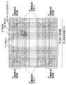
図7は、例えば、Psaltisらによって提案されたシフト多重記録方式の光ディスクシステムを説明する図であり、該光ディスクシステムの光学系の概略構成を示している。 FIG. 7 is a diagram for explaining, for example, a shift multiplex recording optical disc system proposed by Psaltis et al., And shows a schematic configuration of an optical system of the optical disc system.
図7に示すシフト多重記録方式の光ディスクシステム200は、レーザ光源1、ビームエキスパンダ7、ハーフミラー8、ミラー10、空間光変調器2、フーリエ変換レンズ3及び4、ホログラムディスク5、集光レンズ11、及び2次元受光素子アレイ6を有している。
7 includes a laser light source 1, a beam expander 7, a half mirror 8, a mirror 10, a spatial light modulator 2, Fourier
レーザ光源1からの光は,ビームエキスパンダ7でビーム径を拡大された後ハーフミラー8で分割される。分割された一方のビームは、ミラー10により進行方向を変更されて空間光変調器2を通過する。該空間光変調器2を通過したビームは、フーリエ変換レンズ3により集光され、集光されたビームはホログラムディスク5上に信号光20として照射される。他方のビームは、集光レンズ11により集光され、集光された他のビームは参照光22となって、ホログラムディスク5上の信号光20の照射位置と同一位置に照射される。
The light from the laser light source 1 is split by the half mirror 8 after the beam diameter is expanded by the beam expander 7. One of the divided beams is changed in traveling direction by the mirror 10 and passes through the spatial light modulator 2. The beam that has passed through the spatial light modulator 2 is collected by the Fourier transform lens 3, and the collected beam is irradiated onto the hologram disk 5 as
ホログラムディスク5は、2枚のガラス基板間にフォトポリマーなどのホログラム媒質を封止した構成を有し、信号光20と参照光22の干渉縞が該ホログラム媒質に記録される。
The hologram disk 5 has a configuration in which a hologram medium such as a photopolymer is sealed between two glass substrates, and interference fringes of the
ここで、空間光変調器2は、光スイッチを2次元に配列してなる光スイッチ列を有し、入力信号23に応じてそれぞれの光スイッチが独立にオンオフするものであり、各光スイッチは、1ビットの画像情報に相当するセルとなっている。例えば、1024セル×1024セルの空間光変調器2では、1Mビットの情報を同時に表示することが可能である。そして、光ビームが空間光変調器2を通過する際に、空間光変調器2に表示される1Mビットの情報は、2次元の光ビーム列に変換され、フーリエ変換レンズ3により集光される。
Here, the spatial light modulator 2 has an optical switch array in which optical switches are two-dimensionally arranged, and each optical switch is turned on / off independently in response to an
また、記録された信号を再生する際には、ホログラムディスク5に参照光22のみを照射する。すると、ホログラムディスク5からの回折光である再生信号光21はフーリエ変換レンズ4を通過することにより2次元の光ビーム列に変換され、この光ビーム列が2次元受光素子アレイ6上に照射される。
Further, when reproducing the recorded signal, the hologram disk 5 is irradiated with only the reference light 22. Then, the
ここで、2次元受光素子アレイ6は、受光素子を2次元に配列してなるものであり、空間光変調器2における光スイッチの配列に対応したものとなっている。従って、2次元受光素子アレイ6では、上記2次元の光ビーム列における各光ビームが、対応する受光素子によって光電変換され、再生信号24が出力される。
Here, the two-dimensional light
この図7に示した光ディスクシステム200の特徴は、ホログラム媒質の厚みが約1mm程度と厚く、干渉縞が厚いグレーティング、いわゆるブラッググレーティングとして記録されるため、角度多重記録、つまり光ディスクに対する信号光と参照光の入射角を変えて情報を多重記録することが可能となり、光ディスクに記録される情報の大容量化が実現されることである。なお、図7に示す光ディスクシステムでは、参照光22の入射角変化に代えて、球面波参照光の照射位置をシフトすることで角度多重を実現している。すなわちホログラムディスク5をわずかに回転させ記録位置をシフトした際に、媒体各部が感じる参照光入射角がわずかに変化することを利用しているのである。 The optical disk system 200 shown in FIG. 7 is characterized in that the hologram medium has a thickness of about 1 mm and is recorded as a grating having a thick interference fringe, so-called Bragg grating. It is possible to multiplex record information by changing the incident angle of light, and to realize a large capacity of information recorded on the optical disc. In the optical disk system shown in FIG. 7, angle multiplexing is realized by shifting the irradiation position of the spherical wave reference light instead of changing the incident angle of the reference light 22. That is, it utilizes the fact that the reference light incident angle felt by each part of the medium slightly changes when the recording position is shifted by slightly rotating the hologram disk 5.
次に2次元受光素子アレイ6の動作について詳しく説明する。
2次元受光素子アレイでは、2次元の光ビーム列が照射されると、その表面上には2次元に配列された再生信号光スポット列が形成される。
Next, the operation of the two-dimensional light
In the two-dimensional light receiving element array, when a two-dimensional light beam row is irradiated, a reproduction signal light spot row arranged two-dimensionally is formed on the surface.
図8は、この2次元受光素子アレイ上での再生信号光スポット列の配置を示している。それぞれの光スポット25は、2次元受光素子アレイ6の各受光セル9に1対1に対応しており、各光スポットの光強度が、対応する受光セル9により検出される。
FIG. 8 shows the arrangement of reproduction signal light spot rows on the two-dimensional light receiving element array. Each
図8の実線で示された円は、図7に示す光ディスクシステムにおけるフーリエ変換レンズ3、ホログラムディスク5、及び2次元受光素子アレイ6の位置関係が適正であるときの、各受光セル上での再生信号光スポット25を表しており、各光スポット25は対応する受光セル9の中央に位置している。また、図8の点線で示された円は、再生時に光源波長が最適な値より短くなったときの、各受光セル上での再生信号光スポット25aを表しており、各光スポット25の、対応する受光セル9内での位置は、2次元受光素子アレイの中央から離れた受光セルほど、その光スポット25aが受光セルの中心から、受光素子アレイの中心側にずれた位置となっている。
A circle indicated by a solid line in FIG. 8 indicates a position on each light receiving cell when the positional relationship among the Fourier transform lens 3, the hologram disk 5, and the two-dimensional light
つまり、再生時に光源波長が短くなったときには、ホログラムディスク5による参照光の回折角が小さくなってしまうために、再生信号光スポット列の広がりが小さくなる。また、図8には示していないが、ホログラムディスク5が傾いた時には、ディスクの傾きに応じて参照光の回折方向が変化するため、2次元受光素子アレイ上で再生信号光スポット列が適正な位置から平行に移動することになる。また、ホログラムディスク5に偏心があるときには、ディスク回転に合わせて再生信号光スポット列が2次元受光素子アレイ上で回転してしまう。 That is, when the light source wavelength is shortened at the time of reproduction, the diffraction angle of the reference light by the hologram disk 5 becomes small, so the spread of the reproduction signal light spot row becomes small. Although not shown in FIG. 8, when the hologram disk 5 is tilted, the diffraction direction of the reference light changes according to the tilt of the disk, so that the reproduction signal light spot array is appropriate on the two-dimensional light receiving element array. It will move in parallel from the position. Further, when the hologram disk 5 is decentered, the reproduction signal light spot train rotates on the two-dimensional light receiving element array in accordance with the disk rotation.
そして、このように、光源波長のずれやホログラムディスク5の傾きあるいは偏芯が生じたときには、光スポット25の2次元受光素子上での位置が変化し、該光スポット25が、複数の受光セルに跨って照射されるような場合には、それぞれの光スポット25の光強度が正確に検出できなくなってしまう。
When the light source wavelength shift or the hologram disk 5 is tilted or decentered as described above, the position of the
特許文献1には、この位置ずれに対する対策を講じたものが開示されている。
この特許文献1に開示された技術は、図9に示すように、2次元受光素子アレイ6aの四隅の受光セル26を、その受光領域26aを2分割した構造とし、該受光領域の2分割により得られた分割受光領域261及び262からの出力信号の比によって光スポット25の受光素子に対する位置を検出し、光スポット25の位置ずれに応じて、常に2次元受光素子アレイ6aの各受光セルが、対応する光スポット25の変位に追従するよう2次元受光素子アレイ6aの位置を調整するものである。
As shown in FIG. 9, the technique disclosed in Patent Document 1 has a structure in which light receiving cells 26 at four corners of a two-dimensional light receiving element array 6a are divided into two
しかしながら、上記特許文献開示の技術では、光スポットの位置調整を精度よく行うには、2次元受光素子アレイ6のx、y、z3軸方向の位置と、該各軸周りの回転角度とを調整するための合計6軸のサーボ動作が必要であり、位置調整を行う回路構成が複雑となるばかりではなく、回路規模が増大してしまうという課題を有していた。
However, in the technique disclosed in the above patent document, in order to accurately adjust the position of the light spot, the position of the two-dimensional light
本発明は、前記課題を解決するためになされたものであり、サーボ機構により位置調整を行うことなく光スポットの位置ずれに対応することができる2次元受光素子アレイを得ることを目的とする。 The present invention has been made to solve the above-described problems, and an object of the present invention is to obtain a two-dimensional light receiving element array that can cope with a positional deviation of a light spot without adjusting a position by a servo mechanism.
また、本発明は、2次元受光素子アレイの位置調整を行うサーボ機構を用いずに光スポットの位置ずれに対応することができる、構成が簡単で小型化及び低価格化を図ることができるホログラフィック光情報再生装置を提供することを目的とする。 In addition, the present invention can cope with the positional deviation of the light spot without using a servo mechanism for adjusting the position of the two-dimensional light receiving element array, and has a simple structure that can be downsized and reduced in price. An object is to provide a graphic optical information reproducing apparatus.
前記課題を解決するために、本願の2次元受光素子アレイは、2次元配列の複数の光スポットからなる光スポット列を受光して、各光スポットの光強度を検出する2次元受光素子アレイにおいて、受光した光の強度を検出する受光セルを、前記光スポット列に対応する受光領域が形成されるよう複数配列してなる受光部を備え、該受光部の受光領域に対する前記光スポット列の照射位置に応じて、各光スポット毎に、該各光スポットの光強度を検出する複数の受光セルを決定する、ものである。 In order to solve the above problems, two-dimensional photodetector array of the present patent application is to receive light spot columns comprising a plurality of light spots of the two-dimensional array, two-dimensional photodetector array for detecting light intensity of each light spot A light-receiving unit configured to form a plurality of light-receiving cells for detecting the intensity of the received light so that a light-receiving region corresponding to the light spot row is formed, and the light spot row with respect to the light-receiving region of the light-receiving portion A plurality of light receiving cells for detecting the light intensity of each light spot are determined for each light spot according to the irradiation position.
これにより、各光スポットと受光セルとの位置関係に応じて、各光スポットの光強度検出に使用する複数の受光セルが決定されることとなり、波長のずれ等に起因する光スポットのずれに対応することができ、複雑なサーボ機構をもたない簡単な構成で、光スポットの光強度の検出を正確に行うことが可能になる。 As a result, a plurality of light receiving cells to be used for detecting the light intensity of each light spot are determined according to the positional relationship between each light spot and the light receiving cell. Therefore, it is possible to accurately detect the light intensity of the light spot with a simple configuration that does not have a complicated servo mechanism.
また、本願に係る発明は、前記2次元受光素子アレイにおいて、前記光スポット列は、再生の対象となる情報を含む情報再生用光スポットと、前記光スポット列の照射位置の検出に用いる位置検出用光スポットとを含み、前記受光部は、前記光スポット列の情報再生用光スポットを受光して、上記情報を含む再生信号を出力する情報再生受光部と、前記光スポット列の位置検出用光スポットを受光して、前記光スポット列の照射位置を示す位置情報を含む位置検出信号を出力する位置検出受光部とからなる、ものである。 The invention according to the present gun, in the two-dimensional photodetector array, the light spot string includes information reproducing light spots containing information to be reproduced, the position used for the detection of the irradiation position of the light spot string A light spot for detection, and the light receiving unit receives a light spot for information reproduction of the light spot row and outputs a reproduction signal including the information, and a position detection of the light spot row And a position detection light receiving unit that receives a light spot for light and outputs a position detection signal including position information indicating an irradiation position of the light spot row.
これにより、光スポット列の照射位置が、再生信号を出力する情報再生受光部とは別の位置検出受光部により検出されることとなり、位置検出受光部における受光セルの密度を、情報再生受光部におけるものに比べて大きくすることにより、簡単な構成で、光スポット列の照射位置をより高い精度で検出可能となる。 As a result, the irradiation position of the light spot array is detected by a position detection light receiving unit different from the information reproduction light receiving unit that outputs the reproduction signal, and the density of the light receiving cells in the position detection light receiving unit is determined by the information reproduction light receiving unit. By making the size larger than that in the above, the irradiation position of the light spot array can be detected with higher accuracy with a simple configuration.
また、本願に係る発明は、前記2次元受光素子アレイにおいて、前記位置検出用光スポットは、再生の対象となる情報を含み、前記位置検出受光部を構成する受光セルは、前記位置検出用光スポットを受光して、上記情報を含む再生信号を出力する、ものである。 The invention according to the present gun, in the two-dimensional photodetector array, wherein the position detection light spot, comprises the information to be reproduced, the light receiving cells constituting the position detection light receiving unit, for the position detecting A light spot is received and a reproduction signal including the above information is output.
これにより、2次元受光素子アレイの位置検出用受光部からも情報を含む再生信号が出力されることとなり、2次元受光素子アレイ上の受光部をすべて情報の再生に利用することができる。 As a result, a reproduction signal including information is also output from the position detection light-receiving unit of the two-dimensional light-receiving element array, and all the light-receiving parts on the two-dimensional light-receiving element array can be used for information reproduction.
また、本願に係る発明は、前記2次元受光素子アレイにおいて、前記位置検出受光部における、1つの光スポットに対応付けられてその光強度を検出する複数の受光セルの数が、前記情報再生受光部における、1つの光スポットに対応付けられてその光強度を検出する複数の受光セルの数より多い、ものである。 The invention according to this gun, the in the two-dimensional photodetector array, in the position detecting light-receiving part, the number of the plurality of light receiving cells for detecting the light intensity associated with one light spot, the information reproducing More than the number of light receiving cells associated with one light spot and detecting the light intensity in the light receiving unit.
これにより、より正確に、各光スポットの光強度検出に使用する複数の受光セルの位置を決定することができるとともに、2次元受光素子アレイに使用する受光セルの必要以上の増加を防ぎ、装置の小型化、低コスト化を図ることができる。 As a result, the positions of a plurality of light receiving cells used for detecting the light intensity of each light spot can be determined more accurately, and an unnecessary increase in the number of light receiving cells used in the two-dimensional light receiving element array can be prevented. Can be reduced in size and cost.
また、本願に係る発明は、前記2次元受光素子アレイにおいて、前記情報再生受光部では、前記光スポット列の1つの光スポットに対応する受光領域に、3列×3行以上の複数の受光セルを割り当てる、ものである。 The invention according to the present gun, in the two-dimensional photodetector array, in the information reproducing light receiving section, the light receiving region corresponding to one light spot of the light spot columns, 3 columns × 3 rows or more of the plurality of light-receiving Assign cells.
これにより、1つの受光セル中に2つの光スポットが混入されることがなくなり、各光スポットに対応する受光セルからの出力信号を用いて、光スポットの光強度を正確に検出することができる。 Thereby, two light spots are not mixed in one light receiving cell, and the light intensity of the light spot can be accurately detected using the output signal from the light receiving cell corresponding to each light spot. .
また、本願に係る発明は、前記2次元受光素子アレイにおいて、前記位置検出受光部では、前記光スポット列の1つの光スポットに対応する受光領域に、4列×4行以上の複数の受光セルを割り当てる、ものである。 The invention according to the present gun, in the two-dimensional photodetector array, in the position detecting light-receiving part, the light receiving region corresponding to one light spot of the light spot columns, four columns × 4 rows or more of the plurality of light-receiving Assign cells.
これにより、位置検出受光部にて光スポット列の照射位置をより正確に検出することが可能となる。 As a result, the irradiation position of the light spot row can be detected more accurately by the position detection light receiving unit.
また、本願に係る発明は、前記2次元受光素子アレイにおいて、前記複数の受光セルからの出力信号を加算する加算部を複数備え、前記加算部は、前記複数の受光素子が配列されている同じ基板上に集積化されている、ものである。 Further, the invention is related to the gun, in the two-dimensional photodetector array, a plurality of adder for adding output signals from said plurality of light receiving cells, the addition unit, the plurality of light receiving elements are arranged Integrated on the same substrate.
これにより、2次元受光素子アレイの受光セル数の増加に伴う信号帯域の増加を抑制し、装置の小型化、低コスト化を図ることができる。 As a result, an increase in signal bandwidth accompanying an increase in the number of light receiving cells in the two-dimensional light receiving element array can be suppressed, and the size and cost of the apparatus can be reduced.
また、本願のホログラフィック光情報再生装置は、記録媒体上に信号光と参照光の干渉縞の形態で記録されたデジタルデータを再生するホログラフィック光情報再生装置において、前記記録媒体上に参照光を照射する光学系と、前記参照光の照射により前記記録媒体で回折された2次元配列の光スポット列を受光して、前記記録媒体上に記録された情報を含む再生信号を出力する2次元受光素子アレイとを備え、前記2次元受光素子アレイは、受光した光の強度を検出する受光セルを、前記光スポット列に対応する受光領域が形成されるよう複数配列してなる受光部を有し、該受光部の受光領域に対する前記光スポット列の照射位置に応じて、各光スポット毎に、該各光スポットの光強度を検出する複数の受光セルを決定する、ものである。 Also, the holographic optical information reproducing apparatus of the present patent application, in the holographic optical information reproducing apparatus for reproducing digital data recorded in the form of interference fringes of the reference light and the signal light on a recording medium, the reference on the recording medium An optical system for irradiating light, and a two-dimensional array of light spots diffracted by the recording medium by irradiation of the reference light are received, and a reproduction signal including information recorded on the recording medium is output 2 A two-dimensional light-receiving element array, wherein the two-dimensional light-receiving element array includes a light-receiving unit configured by arranging a plurality of light-receiving cells that detect the intensity of received light so that a light-receiving region corresponding to the light spot row is formed. And a plurality of light receiving cells for detecting the light intensity of each light spot is determined for each light spot in accordance with the irradiation position of the light spot row with respect to the light receiving region of the light receiving unit.
これにより、複雑なサーボ機構をもたない、簡単な構成でホログラフィック光情報記録再生装置を構成することができる。 Thereby, the holographic optical information recording / reproducing apparatus can be configured with a simple configuration without a complicated servo mechanism.
また、本願のホログラフィック光情報記録装置は、入力された光ビームを、それぞれ再生信号を含む複数の光信号ビームからなる光ビーム束に変換する空間光変調器を有し、前記光ビーム束を構成する各光信号ビームの情報を記録媒体上に干渉縞として記録するホログラフィック光情報記録装置において、前記空間光変調器は、入力された光ビームを、前記光ビーム束が、前記再生信号を含み、かつ、光ビーム束を受光して再生信号を出力する、受光素子を複数配列してなる2次元受光素子アレイに対する、該光ビーム束の照射位置を検出するための位置検出用信号を含むよう変調する、ものである。 The holographic optical information recording apparatus of the present patent application has a spatial light modulator for converting an input light beam, the light beam bundle comprising a plurality of optical signals beam containing the respective reproduction signal, the light beam bundle In the holographic optical information recording apparatus that records information of each optical signal beam constituting the optical recording medium as interference fringes, the spatial light modulator is configured to input the light beam, and the optical beam bundle is the reproduction signal. A position detection signal for detecting the irradiation position of the light beam bundle with respect to a two-dimensional light receiving element array comprising a plurality of light receiving elements that receive the light beam bundle and output a reproduction signal. Modulate to include.
これにより、本発明にかかる2次元受光素子アレイを用いて、該2次元受光素子アレイに照射される再生信号光スポット列の各光スポット位置を正確に検出することが可能になる。 As a result, it is possible to accurately detect each light spot position of the reproduction signal light spot array irradiated to the two-dimensional light receiving element array using the two-dimensional light receiving element array according to the present invention.
また、本願に係る発明は、前記ホログラフィック光情報記録装置において、前記空間光変調器は、前記位置検出用信号を含む光信号ビームと、前記位置検出用信号を含まない前記再生信号を含む光信号ビームを生成する、ものである。
これにより、より多くの再生対象情報を記録媒体上に記録することが可能になる。
Further, the invention is related to the gun, in the holographic optical information recording apparatus, the spatial light modulator includes the reproduction signal does not include the optical signal beam, the position detection signal containing the position detection signal An optical signal beam is generated.
This makes it possible to record more information to be reproduced on the recording medium.
本発明にかかる2次元受光素子アレイによれば、再生信号光スポット列の各光スポットの光強度を、該光スポット列の照射位置に応じて決定された複数の受光セルにより検出するので、波長のずれ等に起因する光スポットの位置ずれに対応することができ、複雑なサーボ機構をもたない簡単な構成で、光スポットの光強度の検出を正確に行うことが可能になる。 According to the two-dimensional light receiving element array of the present invention, the light intensity of each light spot of the reproduction signal light spot array is detected by a plurality of light receiving cells determined according to the irradiation position of the light spot array. It is possible to cope with the positional deviation of the light spot caused by the deviation of the light spot and the like, and it is possible to accurately detect the light intensity of the light spot with a simple configuration without a complicated servo mechanism.
以下、本発明の実施の形態について説明する。
(実施の形態1)
図1は、本発明の実施の形態1による2次元受光素子アレイを説明する図であり、該2次元受光素子アレイにおける受光セルの配列を示している。
この実施の形態1の2次元受光素子アレイ30は、例えば、図6に示すホログラフィック光情報記録再生装置100の2次元受光素子アレイとして用いられるものである。
Embodiments of the present invention will be described below.
(Embodiment 1)
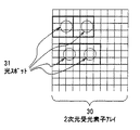
FIG. 1 is a diagram for explaining a two-dimensional light receiving element array according to Embodiment 1 of the present invention, and shows the arrangement of light receiving cells in the two-dimensional light receiving element array.
The two-dimensional light receiving
この2次元受光素子アレイ30の特徴は、ホログラフィックディスクからの再生信号光スポット列の各光スポット31を、隣接する複数個の受光セル35により検出するものである。つまり、この2次元受光素子アレイ30では、再生信号光スポット列が該アレイ30の受光面に入射すると、各光スポット31に対して、その照射領域の中央に位置する受光セルとその周囲に位置する複数の受光セルとが、該各光スポットを検出する受光セルとして割り当てられる。従って、再生信号光スポット列の、2次元受光素子アレイ上での照射位置が変化して、その位置変化前に各光スポット照射領域の中央に位置していた受光セルが、各光スポット照射領域の周辺側に移動すると、各光スポット31には、その位置変化後に照射領域の中央に位置する受光セルとその周囲に位置する複数の受光セルとが再度割り当てられることとなる。
The two-dimensional light receiving
以下具体的に説明する。
この実施の形態1の2次元受光素子アレイ30の4隅部は、該2次元受光素子アレイに対する再生信号光スポット列の照射位置を検出する位置検出用受光部33となっており、2次元受光素子アレイ30の、その4隅に位置する位置検出用受光部33以外の部分が、光スポットの光強度を検出する光スポット受光部36となっている。
This will be specifically described below.
The four corners of the two-dimensional light receiving
この光スポット受光部36は、1つの光スポット31を、これに対応する光検出領域を形成する碁盤目状に配列された合計9個の受光セル、つまり光スポットの照射位置の中央に位置する1個の受光セルと、その周囲に位置する8個の受光セルとにより検出するものである。
The light spot light receiving unit 36 has one
ここで、各受光セルの平面形状は正方形であり、太線で囲まれた正方形領域は、2次元受光素子アレイに対する再生信号光スポット列の位置ずれがない場合に、各光スポットに対する光検出領域となる領域である。そして、この場合には、太線で表されたターゲットとなる光スポット34の光強度は、図中太線で示した正方形領域の縦横3個の画素合計9個の受光セル35からの出力信号を加算することにより検出される。
Here, the planar shape of each light receiving cell is a square, and a square region surrounded by a thick line is a light detection region for each light spot when there is no positional deviation of the reproduction signal light spot row with respect to the two-dimensional light receiving element array. It is an area. In this case, the light intensity of the target light spot 34 indicated by a thick line is obtained by adding output signals from a total of nine light receiving
一方、2次元受光素子アレイに対する再生信号光スポット列の位置ずれが生じて、ターゲットとなる光スポット34が図中点線で示された場所へ移動した時には、光スポット34の光強度は、点線で示された正方形領域を形成する9個の受光セル35からの出力信号の加算により検出される。
On the other hand, when the position of the reproduction signal light spot array with respect to the two-dimensional light receiving element array is displaced and the target light spot 34 moves to the location indicated by the dotted line in the figure, the light intensity of the light spot 34 is indicated by the dotted line. It is detected by adding output signals from the nine light receiving
また、上記位置検出用受光部33は、再生信号光スポット列における位置検出用光スポット32を複数の受光セルで受光し、2次元受光素子アレイに対する再生信号光スポット列の照射位置を検出するための位置検出用信号を生成するものである。ここで、上記位置検出用光スポット32は、記録媒体への情報記録時に空間光変調器によって変調されて記録媒体上に記録された位置検出用情報を含む信号光である。例えば、位置検出用光スポット32には、再生信号光スポット列における光スポットの周波数帯域よりも低い周波数帯域を有するサーボ信号の周波数帯域の信号光を用いる。
The position detection
そして、位置検出用受光部33から出力される位置検出用信号に基づいて、2次元受光素子アレイに対する再生信号光スポット列の位置変化が検出され、該検出された位置変化に基づいて、各光スポット31の光強度検出に使用する9個の受光セル35が各光スポット31毎にそれぞれ割り当てられる。なお、この再生信号光スポット列の照射位置に応じた、各光スポット31の光強度検出に使用する受光セル35の割り当ては、2次元受光素子アレイ外部のホログラフィック光情報再生装置が有する信号処理部(図示せず)で行っても良いし、2次元受光素子アレイ上に搭載された制御部(図示せず)が行うようにしてもよい。
Then, based on the position detection signal output from the position detection
また、この位置検出用受光部33は、より正確な位置検出を行うために、その周辺、つまり光スポット受光部に比べて、1つの光スポットに対応する領域がより細かく細分されていることが望ましく、本実施の形態では、図1に示すように、2次元受光素子アレイの4隅の位置検出用受光部33における1つの光スポットに対応する領域が、周辺の光スポット受光部のものに比べて細かく細分化されている。これによって、該細分化された領域に照射された位置検出用光スポット32の受光量をより細かく検出することが可能となり、この結果、1つの光スポットに割り当てられる複数の受光セルをより正確に決定することが可能になる。
In addition, in order to perform more accurate position detection, the position detection light-receiving
また、この実施の形態1では、位置検出用受光部33は、当該位置検出用受光部33に再生信号光スポット列の光スポット31が照射された場合には、位置検出用受光部33を構成する受光セルが、各光スポットの光強度を検出するための再生信号を生成するものとしている。これにより、再生信号光スポット列の位置検出用光スポット32を、位置検出用情報のみでなく、再生対象となる情報をも含むものとすることが可能となる。また、再生信号光スポット列の光スポットの照射位置のずれ等により、位置検出用受光部33上に再生用の光スポットが照射された場合であっても、当該光スポットに対する再生信号を生成することが可能になる。
なお、照射された光スポットが再生信号光スポット列における位置検出用光スポット32には、位置検出用情報と再生対象となる情報とは、周波数帯域の異なる信号として含まれている。
Further, in the first embodiment, the position detection
It should be noted that the position
次に、1つの光スポット31に対応する受光セルの最適な数について述べる。
図2は、再生信号光スポット列と2次元受光素子アレイ30との位置関係の一例を説明する図であり、1つの光スポット31に対して、縦横2個の合計4個の受光セルを割り当てた場合を示している。なお、図中上側の再生信号光スポット列は、光スポット31の中心が、この光スポットに割り当てられている4つの受光セルの占める領域の中心と一致しているものであり、図中下側の再生信号光スポット列は、光スポット31の中心が、受光セルの横方向の境界線上であって、該光スポットに割り当てられている4つの受光セルの占める領域の中心からずれた位置にあるものである。
Next, the optimum number of light receiving cells corresponding to one
FIG. 2 is a diagram for explaining an example of the positional relationship between the reproduction signal light spot array and the two-dimensional light receiving
通常2次元の光スポットアレイを形成する際には、光スポット径が光スポット間隔の1/2程度となるように設定する。このとき、図2に示すように、1つの光スポット31に対して4個の受光セルを割り当てた場合には、図2のように、光スポット31の中心が、該光スポットに割り当てられている4個の受光セルの中心からずれると、1つの受光セル中に2つの光スポット31が混入してしまう状態が生じる場合がある。この場合には、各受光セルからの出力信号を加算することによってそれぞれの光スポット31の光強度を正確に検出することができない。
Usually, when forming a two-dimensional light spot array, the light spot diameter is set to be about ½ of the light spot interval. At this time, as shown in FIG. 2, when four light receiving cells are assigned to one
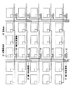
図3は、再生信号光スポット列と2次元受光素子アレイ30との位置関係の他の例を説明する図であり、1つの光スポット31に対して、縦横3個の合計9個の受光セルを割り当てた場合を示している。
FIG. 3 is a diagram for explaining another example of the positional relationship between the reproduction signal light spot array and the two-dimensional light receiving
なお、図中下側の再生信号光スポット列は、光スポット31の中心が、この光スポットに割り当てられている9個の受光セルの占める領域の中心と一致しているものであり、図中上側の再生信号光スポット列は、光スポット31の中心が、受光セルの横方向の境界線上であって、該光スポットに割り当てられている9個の受光セルの占める領域の中心からずれた位置にあるものである。
In the lower side of the reproduction signal light spot row in the figure, the center of the
そして、このように1つの光スポット31に対して縦横3個づつの9個の受光セルを割り当てた場合には、各光スポット31の中心が、該各光スポットに対応する9個の受光セルの占める領域の中心からずれたときでも、1つの受光セル中に2つの光スポット31が混入することなく、各光スポットが、太線の正方形で示した領域、つまり対応する9個の受光セルの占める領域内に収まっている。そのため、この場合には、太線の正方形で示される領域内の受光セルからの出力信号を加算することで光スポット31の光強度が正確に検出できることが分かる。
When nine light receiving cells of three vertical and horizontal are assigned to one
以上より、1つの光スポット31の光強度を、受光セルを縦方向に3個以上、横方向に3個以上配列してなる受光セル群により検出する構成が望ましいことがわかる。ただし、2次元受光素子アレイを構成する受光セルの数が少ないほど、デバイスが簡単かつ安価に構成できるため、2次元受光素子アレイでは、1つの光スポット31に対して、受光セルを縦方向に3個、横方向に3個の合計9個配列してなる受光セル群の各受光セルからの出力信号を加算する構成が最適となる。
From the above, it can be seen that a configuration in which the light intensity of one
また、前述のように、位置検出用受光セルの占める位置検出用受光部では、1つの光スポットに対する受光領域が信号検出用受光セルの占める受光部に比べてより細分化されるのが望ましいため、位置検出用受光部での、1つの光スポットに対応する受光領域の最適な分割は、縦方向に4個、横方向に4個に分割した、16分割である。 In addition, as described above, in the position detection light-receiving unit occupied by the position detection light-receiving cell, it is desirable that the light-receiving region for one light spot is further subdivided compared to the light-receiving unit occupied by the signal detection light-receiving cell. In the position detection light receiving unit, the optimal division of the light receiving region corresponding to one light spot is 16 divisions, which are divided into 4 pieces in the vertical direction and 4 pieces in the horizontal direction.
さてこのように1つの光スポット31を複数の受光セルで検出する2次元受光素子アレイでは、受光セルの数が膨大になる。例えば、再生信号光スポット列が縦方向に1000個、横方向に1000個の2次元の配列を形成しており、1つの光スポット31を9個の受光セルで検出する場合には、受光セルの数は900万個に上る。この信号を毎秒1000ページの速度で読み出すには、つまり2次元受光素子アレイの表面に形成される1枚の画像を毎秒1000枚のレートで読み出すには、2次元受光素子アレイは毎秒90億個のアナログデータを外部に供給しなければならない。
As described above, in the two-dimensional light receiving element array in which one
そして、このような高速のデータ供給を行うためには、複数の信号線を用いることが必要になるが、この場合、デバイスのピン数を増加したり、信号デマルチプレクサを設けたりする必要になるなど、1つの光スポット31を複数の受光セルで検出することは、高コスト化の原因となってしまう。
In order to supply such high-speed data, it is necessary to use a plurality of signal lines. In this case, it is necessary to increase the number of pins of the device or to provide a signal demultiplexer. For example, detecting one
このため、この実施の形態1では、2次元受光素子アレイ30は、図4のように2次元受光素子アレイ30の基板上に各受光セルからの出力信号を加算する加算部を有するものとしている。
For this reason, in the first embodiment, the two-dimensional light receiving
図4は、2次元受光素子アレイ30の基板上に設けられた加算部を説明するための図であり、ここでは、1つの光スポット31に対して、縦に3個、横に3個の合計9個の受光セルが割り当てられている場合を示す。
FIG. 4 is a diagram for explaining an adding unit provided on the substrate of the two-dimensional light receiving
図4において、加算部は、横方向加算部41と縦方向加算部42とから構成され、各受光セル35には受光光量に応じた電気信号を出力する光電変換部43が設置されている。
In FIG. 4, the adding unit includes a
横方向加算部41は、横方向に隣接して並ぶ3つの受光セルに対して1つづつ配置されている。横方向加算部41には、横方向に並んだ近接する5つの受光セルの光電変換部43の出力が接続されており、5つの受光セルのうちの隣接する3つの受光セルからの出力信号を加算して加算結果を縦方向加算部42に出力する。また、縦方向加算部42は、縦方向に隣接して並ぶ3つの受光セルに対して1つづつ配置されている。縦方向加算部42は、縦方向に並んだ近接する5つの横方向加算部41が接続されており、5つの横方向加算部41のうちの隣接する3つの横方向加算部41の出力を加算する。なお、横方向加算部41、縦方向加算部42において、どの3つの出力を選択するかは、前述した位置検出用受光部33から出力される位置検出用信号に基づいて検出した、再生信号光スポット列の各光スポットの照射位置に応じて決定される。
The horizontal
この構成によって、各縦方向加算部42からは、各光スポットに対応する9個の受光セルの出力を加算した信号が出力されることとなる。 With this configuration, each vertical direction adder 42 outputs a signal obtained by adding the outputs of nine light receiving cells corresponding to each light spot.
このような構成とすることで、2次元受光素子アレイ30は、光スポット31の数と等しい数の信号を出力するだけでよく、受光セル35の数の増加による信号帯域の増加を抑制し、装置の低価格化を図ることができる。
With such a configuration, the two-dimensional light receiving
次に、上記実施の形態1の2次元受光素子アレイにて、各光スポットの光強度検出に使用する複数の受光セルを決定する処理について図5を用いて具体的に説明する。 Next, a process for determining a plurality of light receiving cells used for detecting the light intensity of each light spot in the two-dimensional light receiving element array of the first embodiment will be specifically described with reference to FIG.
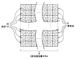
図5は、実施の形態1の2次元受光素子アレイ30にて、各光スポットの光強度検出に使用する複数の受光セルを決定する処理を説明する図である。
FIG. 5 is a diagram illustrating a process of determining a plurality of light receiving cells used for detecting the light intensity of each light spot in the two-dimensional light receiving
図5では、2次元受光素子アレイ上での再生信号光スポット列の照射位置が紙面上の平面内で反時計方向に回転するようにずれた場合の光スポット列の様子が表されている。 FIG. 5 shows the state of the light spot array when the irradiation position of the reproduction signal light spot array on the two-dimensional light receiving element array is shifted so as to rotate counterclockwise within the plane on the paper surface.
位置検出用受光部33に位置検出用光スポット32が照射されると、位置検出用受光部33は、位置検出用光スポット32を複数の受光セル35aで受光し、位置検出用信号を生成する。そして、位置検出用受光部33から出力される位置検出用信号に基づいて、例えば、ホログラフィック光情報再生装置が有する処理部が、再生信号光スポット列の位置の変化を検出し、該検出した再生信号光スポット列の位置変化に基づいて、各光スポット31の光強度検出に使用する9つの受光セル35を各光スポット31毎に決定する。
When the position
図5の例では、右上端の光スポット32が左方向へ位置ずれし、右下端の光スポット32は位置ずれ量がほぼ0となっている。同様に、左上端の光スポット32が左方向へ位置ずれし、左下端の光スポット32は位置ずれ量がほぼ0となっている。
In the example of FIG. 5, the
そして、上記再生信号光スポット列における4隅の位置検出用光スポット以外の光スポットの位置は、上記4隅の位置検出用光スポットの位置情報から内挿によって求められる。
例えば、右上端及び右下端の2つの位置検出用光スポット32の間に位置する光スポット31の位置は、2つの位置検出用光スポット32の位置ずれ量から内挿して求めることができる。そして、再生信号光スポット列の右側端に位置する各光スポットの光強度検出に使用する9個の受光セル35は、図の太線で囲まれた領域内のものに決定される。
The positions of the light spots other than the four corner position detection light spots in the reproduction signal light spot array are obtained by interpolation from the position information of the four corner position detection light spots.
For example, the position of the
以上のように、本発明の実施の形態1による2次元受光素子アレイ30では、再生信号光スポット列の各光スポット31に対して、該再生信号光スポット列の照射位置に応じて複数の受光セルを割り当て、1つの光スポット31の光強度検出を複数の受光セルからの出力信号を用いて行うので、各光スポットに対してその光強度検出に使用する複数の受光セルをどのように割り当てるかによって、波長のずれ等に起因する光スポット31のずれに対応することができ、複雑なサーボ機構をもたない簡単な構成で、各光スポット31の光強度の検出を正確に行うことが可能になる。
As described above, in the two-dimensional light receiving
また、本発明の実施の形態1で説明した2次元受光素子アレイを、ホログラフィック光情報再生装置を組み込むことにより、複雑なサーボ機構をもたない簡易な構成で、信号光と参照光の干渉縞の形態で記録媒体上に記録されたデジタルデータの再生を可能にし、ホログラフィック光情報再生装置の小型化、低コスト化を図ることが可能になる。 In addition, by incorporating the holographic optical information reproducing device into the two-dimensional light receiving element array described in the first embodiment of the present invention, interference between signal light and reference light can be achieved with a simple configuration without a complicated servo mechanism. The digital data recorded on the recording medium in the form of stripes can be reproduced, and the holographic optical information reproducing apparatus can be reduced in size and cost.
なお、本発明の実施の形態1では、位置検出用受光部33を、2次元受光素子アレイ30の4隅部分に配置している、例えば、位置検出用受光部33は2次元受光素子アレイの中央部分にのみ配置してもよい。つまり、位置検出用受光部33は、2次元受光素子アレイ30に対する再生信号光スポット列の照射位置を検出できる位置であれば、2次元受光素子アレイ上のどこに配置してもよい。
In the first embodiment of the present invention, the position detecting
(実施の形態2)
図6は、本発明の実施の形態2によるホログラフィック光情報記録再生装置について説明する図である。
本実施の形態2のホログラフィック光情報記録再生装置100は、図7に示す従来のホログラフィック光情報記録再生装置200における2次元受光素子アレイ6及び空間光変調器2に代えて、実施の形態1の2次元受光素子アレイ6a及び空間光変調器2aを用いたものである。
(Embodiment 2)
FIG. 6 is a diagram for explaining a holographic optical information recording / reproducing apparatus according to Embodiment 2 of the present invention.
A holographic optical information recording / reproducing apparatus 100 according to the second embodiment replaces the two-dimensional light receiving
ここで、上記2次元受光素子アレイ6aは、実施の形態1の2次元受光素子アレイ30と同一のものである。
Here, the two-dimensional light receiving element array 6a is the same as the two-dimensional light receiving
また、上記空間光変調器2aは、ミラー10からの光ビームを、再生の対象となる情報が含まれるとともに、2次元受光素子アレイに対して照射される再生信号光スポット列の各光スポットの照射位置を検出するための位置検出用情報が含まれるよう変調するものである。従って、この位置検出用情報は、再生の対象となる情報とともにホログラムディスク5に記録され、ホログラフィック光情報記録再生装置が再生処理を行う際には、ホログラムディスク5から読み出される。
In addition, the spatial
ところで、2次元受光素子アレイに照射される再生信号光スポット列の各光スポットの照射位置のずれ量は、一般に徐々に大きくなるものであるため、再生時において、常に各光スポットの照射位置を観測しておく必要がないことが多い。 By the way, since the amount of deviation of the irradiation position of each light spot of the reproduction signal light spot array irradiated to the two-dimensional light receiving element array generally increases gradually, the irradiation position of each light spot is always set during reproduction. There is often no need to observe.
そのため、空間光変調器2aは、ミラー10からの光ビームを、常に、位置検出用情報を含む2次元の光ビームが記録されるよう変調するのではなく、位置検出用情報を含む2次元の光ビームと、位置検出用情報を含まない再生対象情報のみを含む2次元の光ビームとが、所定の割合で記録媒体上に記録されるよう変調するものでもよい。この場合、再生時には、一定時間毎に、再生信号光スポット列の各光スポットの照射位置を検出することが可能である。
For this reason, the spatial
このように本実施の形態2によるホログラフィック光情報記録再生装置によれば、再生信号光スポット列の各光スポット31に対して、該光スポットの照射位置に応じた複数の受光セルを割り当る2次元受光素子アレイ30と、再生時に再生信号として検出される再生対象情報に加え、2次元受光素子アレイに対して照射される再生信号光スポット列の各光スポットの照射位置を検出するための位置検出用情報を含む2次元の光ビームが記録されるよう入力される光ビームを変調する空間光変調器2aとを備え、該2次元の光ビームの情報を記録媒体上に干渉縞として記録するので、2次元受光素子アレイの位置調整を行うサーボ機構を用いずに光スポットの位置ずれに対応することができる、構成が簡単で小型化及び低価格化を図ることができるホログラフィック光情報記録再生装置を得ることができる。
As described above, according to the holographic optical information recording / reproducing apparatus according to the second embodiment, a plurality of light receiving cells corresponding to the irradiation position of the light spot are assigned to each
また、この実施の形態2では、空間光変調器2aは、位置検出用情報を含む2次元の光ビームと、位置検出用情報を含まない再生対象情報のみを含む2次元の光ビームとを、各ビームによる記録情報の比率が一定の比率となるよう記録媒体上に記録するので、より多くの再生対象情報を記録媒体上に記録できるようにすることが可能になる。
In the second embodiment, the spatial
また、この実施の形態2では、記録媒体に対してデジタルデータの記録・再生を行うホログラフィック光情報記録再生装置を例にあげて説明したが、デジタルデータの記録のみを行うホログラフィック光情報記録装置、或いは、記録されたデジタルデータの再生のみを行うホログラフィック光情報再生装置に対しても本発明を同様に適用可能である。 In the second embodiment, the holographic optical information recording / reproducing apparatus for recording / reproducing digital data with respect to the recording medium has been described as an example. However, the holographic optical information recording only for recording digital data is described. The present invention can be similarly applied to an apparatus or a holographic optical information reproducing apparatus that only reproduces recorded digital data.
本発明の2次元受光素子アレイ及びこれを用いたホログラフィック光情報再生装置、並びにホログラフィック光情報記録装置は、計算機用大容量外部記憶装置、動画像記録再生装置、動画像再生装置、或いは動画像記録装置に利用することが可能である。 A two-dimensional light receiving element array of the present invention, a holographic optical information reproducing apparatus using the same, and a holographic optical information recording apparatus are a large-capacity external storage device for computers, a moving image recording / reproducing device, a moving image reproducing device, or a moving image. It can be used for an image recording apparatus.
1 レーザ光源
2 空間光変調器
3、4 フーリエ変換レンズ
5 ホログラムディスク
6、6a 2次元受光素子アレイ
7 ビームエキスパンダ
8 ハーフミラー
9 受光セル
10 ミラー
11 集光レンズ
21 再生信号光
22 参照光
23 入力信号
24 再生信号
25 光スポット
26 分割された受光セル
26a 受光領域
30 2次元受光素子アレイ
31 光スポット
32 位置検出用光スポット
33 位置検出用受光部
34 ターゲットとなる光スポット
35,35a 受光セル
36 光スポット受光部
41 横方向加算部
42 縦方向加算部
43 光電変換部
100 ホログラフィック光情報記録再生装置
261、262 分割受光領域
DESCRIPTION OF SYMBOLS 1 Laser light source 2 Spatial
Claims (5)
前記記録媒体上に参照光を照射する光学系と、
受光した光の強度を検出する受光セルを複数配列してなる受光領域を有し、前記受光セルは、前記参照光の照射により前記記録媒体で回折された2次元配列の光スポット列を受光して、前記記録媒体上に記録された情報を含む再生信号を出力する2次元受光素子アレイを備え、
前記受光領域は、2次元配列の光スポット列のうち、再生の対象となる情報を含む情報再生信号用光スポットを受光する情報再生信号受光領域と、2次元配列の光スポット列のうち、前記情報再生信号受光領域における前記情報再生信号用光スポットの照射位置の検出に用いられる位置検出信号用光スポットを受光する複数の位置検出信号受光領域と、を有し、
前記複数の位置検出信号受光領域のそれぞれにおいて、前記位置検出信号用光スポットの入射位置を検出し、検出された前記位置検出信号用光スポットの入射位置から前記情報再生信号受光領域における前記情報再生信号用光スポットの照射位置を内挿して前記情報再生信号用光スポットの照射位置を算出し、
前記情報再生信号用光スポットの照射位置に応じて、各光スポット毎に、前記情報再生信号受光領域の中から前記情報再生信号用光スポットの光強度を検出する複数の受光セルを決定する、
ことを特徴とするホログラフィック光情報再生装置。 In a holographic optical information reproducing apparatus for reproducing digital data recorded in the form of interference fringes of signal light and reference light on a recording medium,
An optical system for irradiating the recording medium with reference light;
It has a light receiving area of the light receiving cells for detecting the intensity of the received light formed by arraying a plurality, wherein the light receiving cell receives light spot column of the two-dimensional array which is diffracted by the recording medium by the irradiation of the reference light Te, comprising a two-dimensional light receiving element array and outputting a reproduced signal containing information recorded on the recording medium,
The light receiving region, of the light spot column of two-dimensional array, and the information reproduction signal light receiving region for receiving the information reproduction signal light spot including information to be reproduced, in the light spot column of the two-dimensional array, wherein It includes a plurality of position detection signal light receiving region for receiving the position detection signal light spot used for detection of the irradiation position of the information reproduction signal optical spot in the information reproducing signal receiving region, and
In each of the plurality of position detection signal light receiving areas , an incident position of the position detection signal light spot is detected, and the information reproduction in the information reproduction signal light receiving area is detected from the detected incident position of the position detection signal light spot. by interpolating the target position of the signal light spot to calculate the irradiation position of the information reproduction signal optical spot,
In accordance with the irradiation position of the information reproduction signal light spot, for each light spot, determine a plurality of light receiving cells for detecting the light intensity of the information reproduction signal light spot from the information reproduction signal light receiving region .
A holographic optical information reproducing apparatus characterized by the above.
前記位置検出信号受光領域上に配列された受光セルの面積は、前記情報再生信号受光領域に配列された受光セルの面積よりも小さい、
ことを特徴とするホログラフィック光情報再生装置。 The holographic optical information reproducing apparatus according to claim 1,
The area of the position detection signal light receiving regions arrayed light receiving cells on is smaller than the area of the light receiving cells arranged in the information re Namashin No. receiving regions,
A holographic optical information reproducing apparatus characterized by the above.
前記情報再生信号受光領域では、
前記光スポット列の1つの光スポットに対応する受光領域に、3列×3行以上の複数の受光セルを割り当てる、
ことを特徴とするホログラフィック光情報再生装置。 In the holographic optical information reproducing device according to any one of claims 1 and 2,
In the information reproduction signal light receiving region ,
Assigning a plurality of light receiving cells of 3 columns × 3 rows or more to a light receiving region corresponding to one light spot of the light spot column;
A holographic optical information reproducing apparatus characterized by the above.
前記位置検出受光部では、
前記光スポット列の1つの光スポットに対応する受光領域に、4列×4行以上の複数の受光セルを割り当てる、
ことを特徴とするホログラフィック光情報再生装置。 In the holographic optical information reproducing device according to any one of claims 1 to 3,
In the position detection light receiving unit,
Assigning a plurality of light receiving cells of 4 columns × 4 rows or more to a light receiving region corresponding to one light spot of the light spot column,
A holographic optical information reproducing apparatus characterized by the above.
前記複数の受光セルからの出力信号を加算する加算部を複数備え、
前記加算部は、前記複数の受光素子が配列されている同じ基板上に集積化されている、
ことを特徴とするホログラフィック光情報再生装置。 In the holographic optical information reproducing device according to any one of claims 1 to 4,
A plurality of addition units for adding output signals from the plurality of light receiving cells,
The adding unit is integrated on the same substrate on which the plurality of light receiving elements are arranged,
A holographic optical information reproducing apparatus characterized by the above.
Priority Applications (1)
| Application Number | Priority Date | Filing Date | Title |
|---|---|---|---|
| JP2004308837A JP4565962B2 (en) | 2003-10-24 | 2004-10-22 | Holographic optical information reproducing device |
Applications Claiming Priority (2)
| Application Number | Priority Date | Filing Date | Title |
|---|---|---|---|
| JP2003365328 | 2003-10-24 | ||
| JP2004308837A JP4565962B2 (en) | 2003-10-24 | 2004-10-22 | Holographic optical information reproducing device |
Publications (3)
| Publication Number | Publication Date |
|---|---|
| JP2005149705A JP2005149705A (en) | 2005-06-09 |
| JP2005149705A5 JP2005149705A5 (en) | 2007-08-09 |
| JP4565962B2 true JP4565962B2 (en) | 2010-10-20 |
Family
ID=34703233
Family Applications (1)
| Application Number | Title | Priority Date | Filing Date |
|---|---|---|---|
| JP2004308837A Expired - Fee Related JP4565962B2 (en) | 2003-10-24 | 2004-10-22 | Holographic optical information reproducing device |
Country Status (1)
| Country | Link |
|---|---|
| JP (1) | JP4565962B2 (en) |
Citations (2)
| Publication number | Priority date | Publication date | Assignee | Title |
|---|---|---|---|---|
| JP2000357342A (en) * | 1999-06-14 | 2000-12-26 | Ricoh Co Ltd | Optical pickup device |
| JP2002216359A (en) * | 2000-11-17 | 2002-08-02 | Matsushita Electric Ind Co Ltd | Holographic optical information recording and regeneration device |
-
2004
- 2004-10-22 JP JP2004308837A patent/JP4565962B2/en not_active Expired - Fee Related
Patent Citations (2)
| Publication number | Priority date | Publication date | Assignee | Title |
|---|---|---|---|---|
| JP2000357342A (en) * | 1999-06-14 | 2000-12-26 | Ricoh Co Ltd | Optical pickup device |
| JP2002216359A (en) * | 2000-11-17 | 2002-08-02 | Matsushita Electric Ind Co Ltd | Holographic optical information recording and regeneration device |
Also Published As
| Publication number | Publication date |
|---|---|
| JP2005149705A (en) | 2005-06-09 |
Similar Documents
| Publication | Publication Date | Title |
|---|---|---|
| US8049942B2 (en) | Multiplexed holographic recording apparatus and method and holographic reproduction apparatus and method | |
| US20080316894A1 (en) | Holographic recording/reproducing apparatus having aperture of variable size | |
| KR101100010B1 (en) | 2-dimension light-receiving array and holographic optical information reproducing apparatus using it and holographic optical information recording apparatus | |
| JPH11126335A (en) | Optical information recording medium, optical information recorder and method therefor as well as optical information reproducing device and method therefor | |
| JP4351551B2 (en) | Holographic recording method, holographic recording apparatus, holographic recording medium, holographic memory reproducing method and apparatus | |
| KR20070038153A (en) | Information carrier, system for reading said information carrier, method of manufacturing said information carrier | |
| JP2021118026A (en) | Holographic storage method and apparatus based on angle-shift multiplexing | |
| US7746752B2 (en) | Servo controlling method of optical information processing apparatus and optical information recording and reproducing apparatus | |
| KR101230508B1 (en) | Data page pixel shaping for holographic recording | |
| US7768894B2 (en) | Holographic storage medium | |
| JP4565962B2 (en) | Holographic optical information reproducing device | |
| KR20080092054A (en) | Hologram device for recording and reading | |
| JP2007025417A (en) | Hologram recording apparatus and method | |
| US20060039047A1 (en) | Holographic device | |
| CN100437772C (en) | Information recording apparatus, information reproducing apparatus and information recording/reproducing apparatus | |
| US20080170479A1 (en) | Optical information storage apparatus and optical recording medium | |
| CN211788163U (en) | Holographic storage device and storage medium based on angle-shift multiplexing | |
| EP1826753B1 (en) | Holographic storage medium | |
| KR100706316B1 (en) | CCD module structure and Hologram Storage consisting of thereof | |
| US20130279318A1 (en) | Data storage and retrieval | |
| US8121009B2 (en) | Apparatus and method for recording data on holographic storage medium | |
| JP2007242145A (en) | Information recorder and information reproducing device | |
| KR20080064359A (en) | Method and apparatus for recording data on a holographic storage medium, and holographic storage medium | |
| JP2006202378A (en) | Method and device fop recording holographic information, hologram recording medium, and method and device for reproducing holographic information | |
| JP2000285482A (en) | Photodetector, signal procesing circuit and optical information reproducing apparatus using the same circuits |
Legal Events
| Date | Code | Title | Description |
|---|---|---|---|
| A521 | Written amendment |
Free format text: JAPANESE INTERMEDIATE CODE: A523 Effective date: 20070622 |
|
| A621 | Written request for application examination |
Free format text: JAPANESE INTERMEDIATE CODE: A621 Effective date: 20070622 |
|
| A977 | Report on retrieval |
Free format text: JAPANESE INTERMEDIATE CODE: A971007 Effective date: 20090701 |
|
| A131 | Notification of reasons for refusal |
Free format text: JAPANESE INTERMEDIATE CODE: A131 Effective date: 20090728 |
|
| A521 | Written amendment |
Free format text: JAPANESE INTERMEDIATE CODE: A523 Effective date: 20090928 |
|
| A131 | Notification of reasons for refusal |
Free format text: JAPANESE INTERMEDIATE CODE: A131 Effective date: 20100428 |
|
| A521 | Written amendment |
Free format text: JAPANESE INTERMEDIATE CODE: A523 Effective date: 20100603 |
|
| TRDD | Decision of grant or rejection written | ||
| A01 | Written decision to grant a patent or to grant a registration (utility model) |
Free format text: JAPANESE INTERMEDIATE CODE: A01 Effective date: 20100706 |
|
| A01 | Written decision to grant a patent or to grant a registration (utility model) |
Free format text: JAPANESE INTERMEDIATE CODE: A01 |
|
| A61 | First payment of annual fees (during grant procedure) |
Free format text: JAPANESE INTERMEDIATE CODE: A61 Effective date: 20100803 |
|
| R150 | Certificate of patent or registration of utility model |
Free format text: JAPANESE INTERMEDIATE CODE: R150 |
|
| FPAY | Renewal fee payment (event date is renewal date of database) |
Free format text: PAYMENT UNTIL: 20130813 Year of fee payment: 3 |
|
| LAPS | Cancellation because of no payment of annual fees |