JP4565078B2 - Winding machine - Google Patents

Winding machine Download PDF

Info

Publication number
JP4565078B2
JP4565078B2 JP2009545017A JP2009545017A JP4565078B2 JP 4565078 B2 JP4565078 B2 JP 4565078B2 JP 2009545017 A JP2009545017 A JP 2009545017A JP 2009545017 A JP2009545017 A JP 2009545017A JP 4565078 B2 JP4565078 B2 JP 4565078B2
Authority
JP
Japan
Prior art keywords
planetary gear
nozzle support
nozzle
winding machine
crank member
Prior art date
Legal status (The legal status is an assumption and is not a legal conclusion. Google has not performed a legal analysis and makes no representation as to the accuracy of the status listed.)
Active
Application number
JP2009545017A
Other languages
Japanese (ja)
Other versions
JPWO2009151028A1 (en
Inventor
健 高地
秀司 大貝
Current Assignee (The listed assignees may be inaccurate. Google has not performed a legal analysis and makes no representation or warranty as to the accuracy of the list.)
LWJ CO., LTD.
Original Assignee
LWJ CO., LTD.
Priority date (The priority date is an assumption and is not a legal conclusion. Google has not performed a legal analysis and makes no representation as to the accuracy of the date listed.)
Filing date
Publication date
Application filed by LWJ CO., LTD. filed Critical LWJ CO., LTD.
Application granted granted Critical
Publication of JP4565078B2 publication Critical patent/JP4565078B2/en
Publication of JPWO2009151028A1 publication Critical patent/JPWO2009151028A1/en
Active legal-status Critical Current
Anticipated expiration legal-status Critical

Links

Images

Classifications

    • HELECTRICITY
    • H02GENERATION; CONVERSION OR DISTRIBUTION OF ELECTRIC POWER
    • H02KDYNAMO-ELECTRIC MACHINES
    • H02K15/00Methods or apparatus specially adapted for manufacturing, assembling, maintaining or repairing of dynamo-electric machines
    • H02K15/08Forming windings by laying conductors into or around core parts
    • H02K15/095Forming windings by laying conductors into or around core parts by laying conductors around salient poles
    • HELECTRICITY
    • H02GENERATION; CONVERSION OR DISTRIBUTION OF ELECTRIC POWER
    • H02KDYNAMO-ELECTRIC MACHINES
    • H02K1/00Details of the magnetic circuit
    • H02K1/06Details of the magnetic circuit characterised by the shape, form or construction
    • H02K1/12Stationary parts of the magnetic circuit
    • H02K1/14Stator cores with salient poles
    • H02K1/146Stator cores with salient poles consisting of a generally annular yoke with salient poles
    • H02K1/148Sectional cores

Description

本発明は巻線機に関する。なお、本出願は2008年6月11日に出願された日本国特許出願2008−153488号に基づく優先権を主張しており、その出願の全内容は本明細書中に参照として組み入れられている。   The present invention relates to a winding machine. Note that this application claims priority based on Japanese Patent Application No. 2008-153488 filed on June 11, 2008, the entire contents of which are incorporated herein by reference. .

巻線機は、例えば、モータや発電機などのステータコアのティース部(磁極ティース)にコイルを巻く装置として用いられる。モータ10のステータコア20は、例えば、図1に示すように、環状の部材で、複数のティース部22がスロット24を挟んで周方向に均等に配設されており、コイル26は、各ティース部22に巻かれている。当該ステータコア20の内側には、ロータ40(回転子)が配設されている。   The winding machine is used, for example, as a device that winds a coil around a teeth portion (magnetic teeth) of a stator core such as a motor or a generator. For example, as shown in FIG. 1, the stator core 20 of the motor 10 is an annular member, and a plurality of teeth portions 22 are evenly arranged in the circumferential direction across the slots 24, and the coil 26 includes each teeth portion. 22 is wound. A rotor 40 (rotor) is disposed inside the stator core 20.

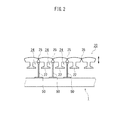
コイル26は、巻線機のノズルをティース部22の外周に沿って移動させて、当該ノズルから繰出される線材をティース部22の外周に巻いている。ステータコア20には、図2に示すように、スロット24の一部を分離できる構造にし、さらにスロット24にヒンジ25を設けて、平らに開くことができる構造を備えたステータコア20がある。かかるステータコア20は、スロット24の開口部が広くなり、コイル26を形成する際に、巻線機1のノズル50の取り回しが容易になる。そして、ティース部22にコイル26を形成してから、ステータコア20を環状に変形させて端部を連結する。このステータコア20のスロット24に対するコイル26の占有率を高めることによって、ティース部22に巻かれたコイル26の量を多くすることができ、モータ10の性能を向上させることができる。   The coil 26 moves the nozzle of the winding machine along the outer periphery of the tooth portion 22, and winds the wire fed from the nozzle around the outer periphery of the tooth portion 22. As shown in FIG. 2, the stator core 20 has a structure in which a part of the slot 24 can be separated and a hinge 25 is provided in the slot 24 so that the slot 24 can be opened flat. In the stator core 20, the opening of the slot 24 is widened, so that the nozzle 50 of the winding machine 1 can be easily handled when the coil 26 is formed. And after forming the coil 26 in the teeth part 22, the stator core 20 is deform | transformed cyclically | annularly and an edge part is connected. By increasing the occupation ratio of the coil 26 to the slot 24 of the stator core 20, the amount of the coil 26 wound around the tooth portion 22 can be increased, and the performance of the motor 10 can be improved.

かかるステータコアに線材を巻く巻線装置は、例えば、日本国特許出願公開2001−8418号公報(特許文献1)、日本国特許出願公開2004−72923号公報(特許文献2)が開示されている。   For example, Japanese Patent Application Publication No. 2001-8418 (Patent Document 1) and Japanese Patent Application Publication No. 2004-72923 (Patent Document 2) are disclosed as winding devices for winding a wire around the stator core.

日本国特許出願公開2001−8418号公報には、大型のクランク機構を備え、アームを揺動させつつノズルの楕円軌道を形成する装置に開示されている。   Japanese Patent Application Publication No. 2001-8418 discloses an apparatus having a large crank mechanism and forming an elliptical orbit of a nozzle while swinging an arm.

また、日本国特許出願公開2004−72923号公報は、正方形及び長方形の軌跡を形成する装置が開示されており、当該軌跡に沿ってノズルを移動させる巻線装置が開示されている。同公報では、互いに直交するX方向およびY方向にそれぞれ延びる長孔状のY方向受動用ガイド孔およびX方向受動用ガイド孔が形成されたノズル支持プレートにノズルが支持されている。そして、ノズル支持プレートは、X方向及びY方向にそれぞれ駆動させる駆動系を組み合わせて制御されている。   Japanese Patent Application Publication No. 2004-72923 discloses a device that forms square and rectangular trajectories, and discloses a winding device that moves a nozzle along the trajectories. In this publication, a nozzle is supported by a nozzle support plate in which a long hole-shaped Y-direction passive guide hole and an X-direction passive guide hole extending in the X direction and the Y direction orthogonal to each other are formed. The nozzle support plate is controlled by combining drive systems that drive in the X direction and the Y direction, respectively.

日本国特許出願公開2001−8418号公報Japanese Patent Application Publication No. 2001-8418 日本国特許出願公開2004−72923号公報Japanese Patent Application Publication No. 2004-72923

巻線装置では、ステータコアに線材を速く巻いて生産性を向上させたい。特許文献1に開示された装置は、大型のクランク機構と揺動スライダ機構とを備え、アームを揺動させつつ進退させ、ノズルの楕円軌道を形成している。かかるアームを揺動させる構造では、ノズルの旋回速度をそれほど速くすることができない。また、特許文献2では、ノズル支持プレートは、X方向およびY方向にそれぞれ駆動させる駆動系を組み合わせて制御されている。このためX方向及びY方向に複雑に力がノズル支持プレートに作用し、ノズルの旋回速度についてもそれほど速くすることができない。   In a winding device, we want to improve productivity by winding a wire around a stator core quickly. The device disclosed in Patent Document 1 includes a large crank mechanism and a swing slider mechanism, and moves the arm back and forth while swinging to form an elliptical orbit of the nozzle. With such a structure that swings the arm, the turning speed of the nozzle cannot be increased so much. Moreover, in patent document 2, the nozzle support plate is controlled combining the drive system which drives each to a X direction and a Y direction. For this reason, force acts on the nozzle support plate in a complicated manner in the X direction and the Y direction, and the turning speed of the nozzle cannot be increased so much.

本発明に係る巻線機は、線材を繰出すノズルと、当該ノズルを支持するノズル支持体と、前記ノズル支持体を旋回させる駆動機構とを備えている。駆動機構は、クランクケースと、内周太陽歯車と、遊星歯車部材と、クランク部材とを備えている。内周太陽歯車は、クランクケースに固定的に配設されている。遊星歯車部材は、内周太陽歯車に遊星歯車を噛み合わせつつ自転および公転する。クランク部材は、内周太陽歯車の中心線と同軸に回転するようにクランクケースに配設され、遊星歯車部材を自転および公転可能に支持する。また、遊星歯車は、内周太陽歯車のピッチ円直径の2分の1のピッチ円直径を有している。遊星歯車部材は、遊星歯車のピッチ円上からずらした位置に遊星歯車の自転および公転に伴って楕円軌道で駆動する作用部を有している。ノズル支持体は当該作用部に連結されている。   The winding machine according to the present invention includes a nozzle that feeds a wire, a nozzle support that supports the nozzle, and a drive mechanism that rotates the nozzle support. The drive mechanism includes a crankcase, an inner peripheral sun gear, a planetary gear member, and a crank member. The inner peripheral sun gear is fixedly disposed on the crankcase. The planetary gear member rotates and revolves while meshing the planetary gear with the inner peripheral sun gear. The crank member is disposed in the crankcase so as to rotate coaxially with the center line of the inner peripheral sun gear, and supports the planetary gear member so that it can rotate and revolve. Further, the planetary gear has a pitch circle diameter that is a half of the pitch circle diameter of the inner circumferential sun gear. The planetary gear member has an action portion that is driven by an elliptical orbit along with the rotation and revolution of the planetary gear at a position shifted from the pitch circle of the planetary gear. The nozzle support is connected to the action part.

この巻線機によれば、駆動機構は、クランク部材によって支持された遊星歯車を、内周太陽歯車に噛み合わせつつ遊星歯車部材を自転および公転させることによって、作用部を楕円軌道で駆動させる。クランク部材の回転運動、および、遊星歯車部材の自転および公転を速くすることによって、ノズル支持体の旋回速度を格段に速くすることができる。   According to this winding machine, the drive mechanism rotates the planetary gear member while rotating the planetary gear supported by the crank member with the inner peripheral sun gear and revolves the planetary gear member, thereby driving the action portion in an elliptical orbit. By making the rotational movement of the crank member and the rotation and revolution of the planetary gear member faster, the turning speed of the nozzle support can be made much faster.

モータの構造を示す図Diagram showing the structure of the motor ステータコアに線材を巻く工程を示す図The figure which shows the process of winding a wire around a stator core 本発明の一実施形態に係る巻線機を示す正面図The front view which shows the winding machine which concerns on one Embodiment of this invention. 本発明の一実施形態に係る巻線機を示す縦断側面図1 is a longitudinal side view showing a winding machine according to an embodiment of the present invention. 本発明の一実施形態に係る巻線機のケーシングを示す正面図The front view which shows the casing of the winding machine which concerns on one Embodiment of this invention. は本発明の一実施形態に係る巻線機の遊星歯車部材を示す側面図である。These are side views which show the planetary gear member of the winding machine which concerns on one Embodiment of this invention. は本発明の一実施形態に係る巻線機の遊星歯車部材を示す正面図である。These are front views which show the planetary gear member of the winding machine which concerns on one Embodiment of this invention. 駆動機構の機構図Mechanism diagram of drive mechanism は本発明の一実施形態に係る巻線機のクランク部材を示す側面図である。These are side views which show the crank member of the winding machine which concerns on one Embodiment of this invention. は本発明の一実施形態に係る巻線機のクランク部材を示す正面図である。These are front views which show the crank member of the winding machine which concerns on one Embodiment of this invention. 遊星歯車部材とクランク部材のアッセンブリを示す側面図Side view showing assembly of planetary gear member and crank member ノズル支持体の旋回状態を示す図The figure which shows the turning state of a nozzle support body ノズル支持体の旋回状態を示す図The figure which shows the turning state of a nozzle support body ノズル支持体の旋回状態を示す図The figure which shows the turning state of a nozzle support body 遊星歯車部材のバランスを示す図The figure which shows the balance of the planetary gear member クランク部材のバランスを示す図Diagram showing the balance of the crank member ケーシングの挿通空間のシール構造を示す図The figure which shows the seal structure of the insertion space of a casing 本発明の他の実施形態に係る巻線機を示す正面図Front view showing a winding machine according to another embodiment of the present invention. 本発明の他の実施形態に係る巻線機を示す縦断側面図A longitudinal side view showing a winding machine according to another embodiment of the present invention. 本発明の他の実施形態に係る巻線機の第1ケース体の内側を示す図。The figure which shows the inner side of the 1st case body of the winding machine which concerns on other embodiment of this invention. 本発明の他の実施形態に係る巻線機の第2ケース体の内側を示す図。The figure which shows the inner side of the 2nd case body of the winding machine which concerns on other embodiment of this invention. 本発明の他の実施形態に係る巻線機のシール構造及び滑り支持部の構造を示す断面図。Sectional drawing which shows the structure of the seal structure of the winding machine which concerns on other embodiment of this invention, and a sliding support part. 本発明の他の実施形態に係る巻線機のシール材を示す断面図。Sectional drawing which shows the sealing material of the winding machine which concerns on other embodiment of this invention. 本発明の他の実施形態に係る巻線機のノズル支持体の軌道を補正するガイドを示す図。The figure which shows the guide which correct | amends the track | orbit of the nozzle support body of the winding machine which concerns on other embodiment of this invention. 本発明の他の実施形態に係る巻線機の駆動機構の変形例を示す図。The figure which shows the modification of the drive mechanism of the winding machine which concerns on other embodiment of this invention.

以下、本発明の一実施形態に係る巻線機を図面に基づいて説明する。なお、異なる実施形態においても同一の作用を奏する部材、部位には同じ符号を付している。   Hereinafter, a winding machine according to an embodiment of the present invention will be described with reference to the drawings. In addition, the same code | symbol is attached | subjected to the member and site | part which show | plays the same effect | action also in different embodiment.

この巻線機1000は、図3及び図4に示すように、ノズル501〜503を支持するノズル支持体600と、ケーシング700と、駆動機構100とを備えている。図4中、符号Pは、ノズル501〜503から供給される線材510を、ステータコア(図示省略)のティース部に巻く、巻線機1000の捲回部を示している。   As shown in FIGS. 3 and 4, the winding machine 1000 includes a nozzle support 600 that supports the nozzles 501 to 503, a casing 700, and a drive mechanism 100. In FIG. 4, the code | symbol P has shown the winding part of the winding machine 1000 which winds the wire 510 supplied from the nozzles 501-503 around the teeth part of a stator core (illustration omitted).

≪ノズル支持体600≫
ノズル支持体600は、図3に示すように、ノズル501〜503を支持している。ノズル501〜503は、線材を繰出す線材の供給部である。この実施形態では、ノズル支持体600は、略ひし形のプレート部材で構成されている。そして、ステータコア20の3つのティース部22(図2参照)に、同時に線材510を巻くことができるように、ノズル支持体600の略中央部に3つのノズル501〜503が所定の間隔で横に並べて取り付けられている。このノズル支持体600は、ケーシング700に収容されており、駆動機構100の作用部105に連結されて楕円軌道Aで旋回する。
Nozzle support 600≫
As shown in FIG. 3, the nozzle support 600 supports the nozzles 501 to 503. The nozzles 501 to 503 are wire supply units for feeding the wire. In this embodiment, the nozzle support body 600 is comprised by the substantially rhombus plate member. Then, the three nozzles 501 to 503 are placed at a predetermined interval in the substantially central portion of the nozzle support 600 so that the wire 510 can be wound around the three teeth portions 22 (see FIG. 2) of the stator core 20 at the same time. Installed side by side. The nozzle support 600 is accommodated in the casing 700, and is connected to the action part 105 of the drive mechanism 100 so as to turn on an elliptical orbit A.

≪駆動機構100≫
次に、駆動機構100を説明する。駆動機構100は、ノズル支持体600を旋回させる機構である。この実施形態では、図3に示すように、ノズル支持体600の両側部620、630(この実施形態では、ひし形の頂点部分)が、それぞれ駆動機構100の作用部105に連結されている。
<< Drive mechanism 100 >>
Next, the drive mechanism 100 will be described. The drive mechanism 100 is a mechanism that rotates the nozzle support 600. In this embodiment, as shown in FIG. 3, both side portions 620 and 630 (in this embodiment, rhombus apex portions) of the nozzle support 600 are respectively connected to the action portion 105 of the drive mechanism 100.

この駆動機構100は、図4及び図5に示すように、クランクケース101と、内周太陽歯車102と、遊星歯車部材103と、クランク部材104とを備えている。上述した作用部105は、遊星歯車部材103に設けられている。   As shown in FIGS. 4 and 5, the drive mechanism 100 includes a crankcase 101, an inner peripheral sun gear 102, a planetary gear member 103, and a crank member 104. The action part 105 described above is provided on the planetary gear member 103.

≪クランクケース101≫
クランクケース101は、図4に示すように、駆動機構100の各部材を収容するケースである。この実施形態では、クランクケース101は、底を有する筒状の部材であり、図4では、底部111を右側に向け、開口112を左側に向けて横向きに配設されている。このクランクケース101は、開口112側の第1部材101aと、底部111側の第2部材101bとを、軸方向の中間部で組み合わせた構造を備えている。この実施形態では、クランクケース101は、開口112の端部が上述したケーシング700に取り付けられている。
≪Crankcase 101≫
As shown in FIG. 4, the crankcase 101 is a case that accommodates each member of the drive mechanism 100. In this embodiment, the crankcase 101 is a cylindrical member having a bottom. In FIG. 4, the crankcase 101 is disposed laterally with the bottom 111 facing the right side and the opening 112 facing the left side. The crankcase 101 has a structure in which a first member 101a on the opening 112 side and a second member 101b on the bottom 111 side are combined at an intermediate portion in the axial direction. In this embodiment, the crankcase 101 has an end of the opening 112 attached to the casing 700 described above.

クランクケース101の内部には、クランク部材104や内周太陽歯車102など、駆動機構100の各部材を収容するスペースが形成されている。クランクケース101の底部111には、クランク部材104の軸部154を挿通させる挿通穴113が、底部111の中心に形成されている。   Inside the crankcase 101, spaces for accommodating the members of the drive mechanism 100 such as the crank member 104 and the inner peripheral sun gear 102 are formed. An insertion hole 113 through which the shaft portion 154 of the crank member 104 is inserted is formed in the bottom portion 111 of the crankcase 101 at the center of the bottom portion 111.

≪内周太陽歯車102≫
内周太陽歯車102は、内周面に歯を有する内歯車であり、クランクケース101の内周面の中間位置に形成された段差121に固定されている。
Inner sun gear 102≫
The inner peripheral sun gear 102 is an inner gear having teeth on the inner peripheral surface, and is fixed to a step 121 formed at an intermediate position on the inner peripheral surface of the crankcase 101.

≪遊星歯車部材103≫
遊星歯車部材103は、図4に示すように、内周太陽歯車102に遊星歯車131を噛み合わせつつ自転及び公転する部材である。この実施形態では、遊星歯車部材103は、図6A及び図6Bに示すように、遊星歯車131と遊星軸132によって構成されている。遊星歯車131は、外周面に歯を有する外歯車であり、内周太陽歯車102のピッチ円直径の2分の1のピッチ円直径を有している。すなわち、図7に示すように、遊星歯車131のピッチ円103cの半径r1と、内周太陽歯車102のピッチ円102cの半径r2との比は、r1:r2=1:2である。この実施形態では、図4及び図9に示すように、遊星歯車131の中心部にはボス部141が設けられており、当該ボス部141が、遊星軸132の端部に装着されている。遊星歯車部材103は、遊星歯車131の回転軸方向の無限遠点から見て、遊星歯車131のピッチ円103c上からずらした位置に遊星歯車131の自転及び公転に伴って楕円軌道Aで駆動する作用部105を有している。図7中、c3は、作用部105の中心を示している。
Planetary gear member 103≫
As shown in FIG. 4, the planetary gear member 103 is a member that rotates and revolves while the planetary gear 131 is engaged with the inner circumferential sun gear 102. In this embodiment, the planetary gear member 103 includes a planetary gear 131 and a planetary shaft 132 as shown in FIGS. 6A and 6B. The planetary gear 131 is an external gear having teeth on the outer peripheral surface, and has a pitch circle diameter that is a half of the pitch circle diameter of the inner peripheral sun gear 102. That is, as shown in FIG. 7, the ratio between the radius r1 of the pitch circle 103c of the planetary gear 131 and the radius r2 of the pitch circle 102c of the inner peripheral sun gear 102 is r1: r2 = 1: 2. In this embodiment, as shown in FIGS. 4 and 9, a boss 141 is provided at the center of the planetary gear 131, and the boss 141 is attached to the end of the planetary shaft 132. The planetary gear member 103 is driven in the elliptical orbit A along with the rotation and revolution of the planetary gear 131 at a position shifted from the pitch circle 103c of the planetary gear 131 when viewed from the infinity point in the rotation axis direction of the planetary gear 131. An action part 105 is provided. In FIG. 7, c <b> 3 indicates the center of the action part 105.

≪作用部105≫
作用部105は、この実施形態では、図6Aに示すように、遊星軸132に遊星歯車131が装着されたのとは反対側の端部に設けられている。作用部105は、ピン形状の部位で、図6Bに示すように、遊星軸132の中心軸c2から半径方向にずれた位置に設けられている。この作用部105は、図7に示すように、遊星歯車131のピッチ円103cよりも内側に配設されている。
<< Action part 105 >>
In this embodiment, as shown in FIG. 6A, the action portion 105 is provided at the end opposite to the planetary gear 131 mounted on the planetary shaft 132. The action part 105 is a pin-shaped part, and is provided at a position shifted in the radial direction from the central axis c2 of the planetary shaft 132, as shown in FIG. 6B. As shown in FIG. 7, the action portion 105 is disposed inside the pitch circle 103 c of the planetary gear 131.

≪遊星歯車部材103に取り付けられたバランサー≫
また、この実施形態では、遊星歯車部材103は、作用部105が設けられた側の端部に第1カウンターウェイト145が設けられ、反対側の端部に第1バランサー146が取り付けられている。当該第1カウンターウェイト145と、第1バランサー146については、後で詳述する。
≪Balancer attached to planetary gear member 103≫
In this embodiment, the planetary gear member 103 is provided with a first counterweight 145 at the end on the side where the action portion 105 is provided, and a first balancer 146 at the end on the opposite side. The first counterweight 145 and the first balancer 146 will be described in detail later.

≪クランク部材104≫
次に、このクランク装置におけるクランク部材を説明する。
クランク部材104は、図4及び図7に示すように、内周太陽歯車102の中心線と同軸に回転するようにクランクケース101に配設されている。そして、クランク部材104は、遊星歯車部材103を自転および公転可能に支持している。
≪Crank member 104≫
Next, the crank member in this crank apparatus will be described.
As shown in FIGS. 4 and 7, the crank member 104 is disposed in the crankcase 101 so as to rotate coaxially with the center line of the inner sun gear 102. The crank member 104 supports the planetary gear member 103 so that it can rotate and revolve.

この実施形態では、クランク部材104は、図8Aに示すように、片側が太く、反対側が細い軸部材である。片側の太い軸部151には、図8A、図8B及び図9に示すように、上述した遊星歯車部材103を装着する装着穴152が、当該片側の端面から軸方向に形成されている。当該装着穴152の中心線c2は、図7に示すように、クランク部材104の回転軸c1から遊星歯車131のピッチ円103cの半径r1の距離だけずれており、遊星歯車131のピッチ円103cの中心線c2に一致している。また、図8A及び図9に示すように、このクランク部材104の中間部153は当該太い軸部151よりも少し細く形成されている。当該中間部153において、太い軸部151に形成された装着穴152の底部は、図中の符号152aで示すように、クランク部材104の側面に開口している。   In this embodiment, as shown in FIG. 8A, the crank member 104 is a shaft member that is thick on one side and thin on the opposite side. As shown in FIG. 8A, FIG. 8B, and FIG. 9, a mounting hole 152 for mounting the above planetary gear member 103 is formed in the axial direction from the end surface of the one side. As shown in FIG. 7, the center line c <b> 2 of the mounting hole 152 is shifted from the rotation axis c <b> 1 of the crank member 104 by a distance of the radius r <b> 1 of the pitch circle 103 c of the planetary gear 131. It coincides with the center line c2. Further, as shown in FIGS. 8A and 9, the intermediate portion 153 of the crank member 104 is formed to be slightly thinner than the thick shaft portion 151. In the intermediate portion 153, the bottom portion of the mounting hole 152 formed in the thick shaft portion 151 is open to the side surface of the crank member 104 as indicated by reference numeral 152a in the drawing.

≪動力伝達、プーリ159≫
この実施形態では、クランク部材104の当該中間部153から伸びる軸部154には、キー溝156が切られ、キー157を介してボス158が装着されている。当該ボス158のフランジには、図4および図8に示すように、動力源としてのモータ200からタイミングベルト201が掛けまわされるプーリ159が取り付けられている。
≪Power transmission, pulley 159≫
In this embodiment, a key groove 156 is cut in a shaft portion 154 extending from the intermediate portion 153 of the crank member 104, and a boss 158 is attached via a key 157. As shown in FIGS. 4 and 8, a pulley 159 around which a timing belt 201 is wound from a motor 200 as a power source is attached to the flange of the boss 158.

≪クランク部材104に取り付けられたバランサー≫
また、この実施形態では、クランク部材104は、図8に示すように、前記片側の端部に第2カウンターウェイト161が設けられ、反対側の端部に第2バランサー162が取り付けられている。この実施形態では、第2バランサー162は、上述したプーリ159に取り付けられている。当該第2カウンターウェイト161と、第2バランサー162については、後で詳述する。
≪Balancer attached to crank member 104≫
In this embodiment, as shown in FIG. 8, the crank member 104 is provided with a second counterweight 161 at the end on one side and a second balancer 162 on the end on the opposite side. In this embodiment, the second balancer 162 is attached to the pulley 159 described above. The second counterweight 161 and the second balancer 162 will be described in detail later.

≪遊星歯車部材103とクランク部材104の取り付け構造≫
この実施形態では、図4及び図9に示すように、遊星歯車部材103は、軸受181、182を介在させてクランク部材104の装着穴152に回動自在に装着されている。遊星歯車部材103は、第1カウンターウェイト145および作用部105が、クランク部材104の装着穴152から外に出た状態で、装着穴152に装着されている。また、遊星軸132は、図4および図9に示すように、クランク部材104の装着穴152の底部に形成された開口152aに到達している。当該遊星軸132の端部に取り付けられた遊星歯車131の歯面は、クランク部材104の装着穴152の底部に形成された開口152aからクランク部材104の外に露出している。
<< Attachment structure of planetary gear member 103 and crank member 104 >>
In this embodiment, as shown in FIGS. 4 and 9, the planetary gear member 103 is rotatably mounted in the mounting hole 152 of the crank member 104 with bearings 181 and 182 interposed therebetween. The planetary gear member 103 is mounted in the mounting hole 152 in a state in which the first counterweight 145 and the action portion 105 protrude from the mounting hole 152 of the crank member 104. Further, as shown in FIGS. 4 and 9, the planetary shaft 132 reaches an opening 152 a formed at the bottom of the mounting hole 152 of the crank member 104. The tooth surface of the planetary gear 131 attached to the end of the planetary shaft 132 is exposed to the outside of the crank member 104 through an opening 152 a formed at the bottom of the mounting hole 152 of the crank member 104.

≪クランクケース101への取り付け構造≫
遊星歯車部材103とクランク部材104のアッセンブリは、図4に示すように、クランクケース101に装着されている。クランク部材104は、軸受183、184を介在させて、クランクケース101に回動自在に装着されている。クランク部材104は、クランクケース101に固定された内周太陽歯車102のピッチ円102cの中心線c1と同軸で回転するように装着されている。遊星歯車131は、クランク部材104の装着穴152の底部に形成された開口152aから露出しており、内周太陽歯車102に噛み合う。また、クランク部材104の軸部154が挿通される挿通穴113には、軸受184と、プーリ159を取り付けるボス158との間にスペーサ185と、シール186が装着されている。
≪Mounting structure to crankcase 101≫
The assembly of the planetary gear member 103 and the crank member 104 is mounted on the crankcase 101 as shown in FIG. The crank member 104 is rotatably mounted on the crankcase 101 with bearings 183 and 184 interposed therebetween. The crank member 104 is mounted so as to rotate coaxially with the center line c1 of the pitch circle 102c of the inner peripheral sun gear 102 fixed to the crankcase 101. The planetary gear 131 is exposed from an opening 152 a formed at the bottom of the mounting hole 152 of the crank member 104 and meshes with the inner peripheral sun gear 102. A spacer 185 and a seal 186 are mounted between the bearing 184 and the boss 158 to which the pulley 159 is attached in the insertion hole 113 through which the shaft portion 154 of the crank member 104 is inserted.

≪作用部105の軌道≫
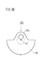
上述したように遊星歯車部材103は、内周太陽歯車102との噛み合い、クランク部材104の回転に応じて、自転及び公転する。クランク部材104の軸方向から平面的に観察すると、この駆動機構100は、図7に示すように、遊星歯車部材103のピッチ円103cの半径r1と、内周太陽歯車102のピッチ円102cの半径r2との比は、r1:r2=1:2の関係になっている。また、作用部105は、遊星歯車部材103の回転中心軸c2から径方向にピッチ円103cの半径r1よりも短い距離r3だけずれている。
≪Track of action part 105≫
As described above, the planetary gear member 103 meshes with the inner peripheral sun gear 102 and rotates and revolves according to the rotation of the crank member 104. When viewed planarly from the axial direction of the crank member 104, the drive mechanism 100 has a radius r 1 of the pitch circle 103 c of the planetary gear member 103 and a radius of the pitch circle 102 c of the inner peripheral sun gear 102 as shown in FIG. The ratio with r2 is r1: r2 = 1: 2. Further, the action portion 105 is displaced from the rotation center axis c2 of the planetary gear member 103 in the radial direction by a distance r3 that is shorter than the radius r1 of the pitch circle 103c.

この駆動機構100によれば、遊星歯車部材103は、クランク部材104の装着穴152によって、自転及び公転可能に支持されている。クランク部材104が回転すると、遊星歯車部材103は内周太陽歯車102と噛合しながら自転および公転する。遊星歯車部材103は、1回公転する毎に2回自転する。この際、作用部105は楕円軌道Aを描く。なお、楕円軌道Aの形状は、作用部105を設ける位置によって変わる。所望の楕円軌道Aが得られるように、作用部105の位置を設定するとよい。   According to the drive mechanism 100, the planetary gear member 103 is supported by the mounting hole 152 of the crank member 104 so as to be capable of rotating and revolving. When the crank member 104 rotates, the planetary gear member 103 rotates and revolves while meshing with the inner peripheral sun gear 102. The planetary gear member 103 rotates twice every revolution. At this time, the action unit 105 draws an elliptical orbit A. Note that the shape of the elliptical orbit A varies depending on the position where the action portion 105 is provided. The position of the action part 105 may be set so that a desired elliptical trajectory A is obtained.

≪ノズル支持体600の取付構造≫
この実施形態では、図5に示すように、ケーシング700の中央部にノズル501〜503が旋回するノズル旋回空間710が在り、当該ノズル旋回空間710の両側に形成された開口715,716にそれぞれ駆動機構100が取り付けられている。また、この巻線機1000では、2つの駆動機構100のプーリ159と、モータ200のプーリ210とにタイミングベルト201を掛けまわし、駆動機構100の作用部105が旋回するタイミングが調整されている。これにより2つの駆動機構100の作用部105は、図3に示すように、それぞれ同期して縦長の楕円軌道Aを描く。略ひし形のプレート部材で構成されたノズル支持体600は、図3に示すように、両側部620、630(この実施形態では、ひし形の両側の頂点部分)が、駆動機構100の作用部105にそれぞれ軸受640(図4参照)を介して連結されている。
<< Mounting structure of nozzle support 600 >>
In this embodiment, as shown in FIG. 5, there is a nozzle swirl space 710 in which the nozzles 501 to 503 swirl in the center of the casing 700, and the nozzles 715 and 716 formed on both sides of the nozzle swirl space 710 are respectively driven. A mechanism 100 is attached. In the winding machine 1000, the timing belt 201 is wound around the pulley 159 of the two drive mechanisms 100 and the pulley 210 of the motor 200, and the timing at which the action portion 105 of the drive mechanism 100 turns is adjusted. Thereby, the action part 105 of the two drive mechanisms 100 draws the vertically long elliptical orbit A in synchronization with each other as shown in FIG. As shown in FIG. 3, the nozzle support 600 formed of a substantially rhombus plate member has both side portions 620 and 630 (in this embodiment, apex portions on both sides of the rhombus) on the action portion 105 of the drive mechanism 100. Each is connected via a bearing 640 (see FIG. 4).

≪ノズル支持体600、ノズル501〜503の軌道≫
ノズル支持体600は、上述した駆動機構100の作用部105に支持されて、上下方向に縦長の楕円軌道Aに沿って旋回する。この巻線機1000では、線材を繰出すノズル501〜503は、図3および図10〜図12に示すように、ノズル支持体600に支持されており、ノズル支持体600の旋回に伴って、楕円軌道Aで回動する。
<< Track of nozzle support 600 and nozzles 501 to 503 >>
The nozzle support 600 is supported by the action part 105 of the drive mechanism 100 described above, and swivels along a vertically long elliptical orbit A in the vertical direction. In the winding machine 1000, the nozzles 501 to 503 for feeding out the wire are supported by the nozzle support 600 as shown in FIGS. 3 and 10 to 12, and as the nozzle support 600 turns, It rotates on an elliptical orbit A.

ノズル支持体600と駆動機構100の作用部105との連結構造は、この実施形態では、作用部105に軸受640を介在させて、ノズル支持体600を取り付けている。また、この実施形態では、ノズル支持体600の離れた2箇所の位置(両側部620、630)が異なる駆動機構100の作用部105に連結されている。
駆動機構100は、タイミングベルト201によって、タイミングが調整されており、駆動機構100の作用部105は、図3および図10から図12に示すように、それぞれ同期して同じ縦長の楕円軌道Aを描く。この際、駆動機構100内の内周太陽歯車102と遊星歯車131とに生じるバックラッシュや、駆動機構100のプーリ159とタイミングベルト201とのバックラッシュや、各部材の加工精度や、各部材の組付精度などによって、異なる駆動機構100の作用部105の楕円軌道Aが微妙にずれることもある。
In this embodiment, the connection structure between the nozzle support 600 and the action part 105 of the drive mechanism 100 is such that the nozzle support 600 is attached to the action part 105 with a bearing 640 interposed therebetween. In this embodiment, two positions (both side portions 620 and 630) of the nozzle support body 600 that are separated from each other are connected to the action portion 105 of the drive mechanism 100.
The timing of the drive mechanism 100 is adjusted by the timing belt 201, and the action unit 105 of the drive mechanism 100 synchronizes with the same elliptical orbit A that is the same as shown in FIGS. 3 and 10 to 12, respectively. Draw. At this time, backlash generated in the inner sun gear 102 and the planetary gear 131 in the drive mechanism 100, backlash between the pulley 159 and the timing belt 201 of the drive mechanism 100, processing accuracy of each member, Depending on the assembling accuracy, the elliptical orbit A of the action portion 105 of the different drive mechanism 100 may be slightly shifted.

この実施形態では、ノズル支持体600と駆動機構100の作用部105との連結箇所は、1箇所はノズル支持体600に対する駆動機構100の作用部105の位置が変わらず、他はノズル支持体600に対する駆動機構100の作用部105の位置が変位可能な構造を備えている。すなわち、この実施形態では、図3に示す右側の駆動機構100の作用部105をノズル支持体600に連結する部位において、ノズル支持体600に軸受640を取り付ける穴721(図4参照)を微妙に長穴とし、ノズル支持体600に対して、軸受640が少し動けるようにしている。これによって、異なる駆動機構100の作用部105の楕円軌道Aが相対的に微妙にずれるのに応じて、ノズル支持体600に対して当該軸受640が動き、当該ずれを吸収する。これによって、ノズル支持体600の動作を滑らかにしている。   In this embodiment, the position of the action part 105 of the drive mechanism 100 relative to the nozzle support 600 does not change at one place where the nozzle support 600 and the action part 105 of the drive mechanism 100 are connected. The position of the action part 105 of the drive mechanism 100 with respect to is provided. In other words, in this embodiment, a hole 721 (see FIG. 4) for attaching the bearing 640 to the nozzle support 600 is delicately provided at a portion where the action portion 105 of the right drive mechanism 100 shown in FIG. A long hole is provided so that the bearing 640 can move a little with respect to the nozzle support 600. Accordingly, the bearing 640 moves with respect to the nozzle support 600 in accordance with the relative subtle shift of the elliptical orbit A of the action portion 105 of the different drive mechanism 100, and absorbs the deviation. Thereby, the operation of the nozzle support 600 is made smooth.

なお、この実施形態では、ノズル支持体600の離れた2箇所の位置が、同じ楕円軌道で同期して旋回する駆動機構100の作用部105にそれぞれ連結されている。図示は省略するが、駆動機構100の作用部105に掛かる負荷を軽減するため、ノズル支持体600の2箇所以上の位置を、同じ楕円軌道で同期して旋回する駆動機構100の作用部105に連結することも可能である。この場合、駆動機構100の作用部105に連結されたノズル支持体600の位置のうち1箇所は、ノズル支持体600に対する駆動機構100の作用部105の位置が変わらず、他はノズル支持体600に対する駆動機構100の作用部105の位置が変位可能であるように構成するとよい。これによって、異なる駆動機構100の作用部105の楕円軌道Aが相対的に微妙にずれを許容することができ、ノズル支持体600の動作を滑らかにできる。   Note that, in this embodiment, the two distant positions of the nozzle support 600 are respectively connected to the action portion 105 of the drive mechanism 100 that rotates in the same elliptical orbit. Although illustration is omitted, in order to reduce the load applied to the action part 105 of the drive mechanism 100, the action part 105 of the drive mechanism 100 that rotates two or more positions of the nozzle support 600 synchronously on the same elliptical orbit is used. It is also possible to connect. In this case, the position of the action part 105 of the drive mechanism 100 with respect to the nozzle support 600 does not change in one position among the positions of the nozzle support body 600 connected to the action part 105 of the drive mechanism 100, and the other is the nozzle support body 600. The position of the action part 105 of the drive mechanism 100 with respect to the position may be configured to be displaceable. As a result, the elliptical orbit A of the action portion 105 of the different drive mechanism 100 can be allowed to be relatively delicately shifted, and the operation of the nozzle support 600 can be made smooth.

ノズル支持体600に対する駆動機構100の作用部105の位置を変位可能にする構成は、上述した実施形態に限定されない。   The configuration that allows the position of the action part 105 of the drive mechanism 100 relative to the nozzle support 600 to be displaced is not limited to the above-described embodiment.

≪巻線機1000の作用≫
従来技術として挙げた特許文献1では、大きなアームの揺動を伴うものであり、特許文献2では、X方向、Y方向へのガイドを組み合わせた構造である。これらの構造上、慣性力が大きく作用するためノズル支持体を速く回転させることに向いておらず、このため、線材をステータコアに捲回する工程に係る時間を短縮することが難しい。
これに対して、上述した巻線機1000は、図4および図7に示すように、ノズル支持体600は、駆動機構100の作用部105に連結されて楕円軌道Aで旋回する。この巻線機1000によれば、駆動機構100は、クランク部材104によって支持された遊星歯車131を、内周太陽歯車102に噛み合わせつつ遊星歯車部材103を自転および公転させることによって、作用部105を楕円軌道Aでスムーズに駆動させることができる。クランク部材104の回転運動、および、遊星歯車部材103の自転および公転は、一連の連続運動であり、上述した特許文献1、特許文献2の構造に比べて、慣性力による損失が少なく、効率よく駆動させることができる。このため、従来技術として挙げた特許文献1、2に比べて、ノズル支持体600の旋回速度を格段に速くすることができる。
≪Operation of winding machine 1000≫
Patent Document 1 cited as the prior art involves a large arm swing, and Patent Document 2 has a structure in which guides in the X and Y directions are combined. Due to these structures, inertia force acts greatly, so that it is not suitable for rotating the nozzle support quickly, and therefore it is difficult to shorten the time required for the step of winding the wire around the stator core.
On the other hand, in the winding machine 1000 described above, as shown in FIGS. 4 and 7, the nozzle support 600 is connected to the action part 105 of the drive mechanism 100 and swivels on the elliptical orbit A. According to this winding machine 1000, the driving mechanism 100 rotates and revolves the planetary gear member 103 while meshing the planetary gear 131 supported by the crank member 104 with the inner peripheral sun gear 102, thereby causing the action portion 105. Can be smoothly driven on the elliptical orbit A. The rotational movement of the crank member 104 and the rotation and revolution of the planetary gear member 103 are a series of continuous movements, and less loss due to inertial force than the structures of Patent Document 1 and Patent Document 2 described above, and efficient. It can be driven. For this reason, the turning speed of the nozzle support 600 can be significantly increased as compared with Patent Documents 1 and 2 cited as the prior art.

この実施形態では、図3に示すように、ノズル支持体600の離れた少なくとも2箇所の位置(この実施形態では、両側部620、630(ひし形のノズル支持体600の両側の頂点部分))が、同じ楕円軌道で同期して旋回する駆動機構100の作用部105にそれぞれ連結されている。このため、ノズル支持体600の旋回を安定させることができる。   In this embodiment, as shown in FIG. 3, at least two positions (in this embodiment, both side portions 620 and 630 (vertical apex portions on both sides of the rhombus nozzle support body 600)) of the nozzle support body 600 are located. These are connected to the action part 105 of the drive mechanism 100 that rotates in the same elliptical orbit synchronously. For this reason, the turning of the nozzle support 600 can be stabilized.

また、この実施形態では、図7に示すように、作用部105は、遊星歯車131のピッチ円103cの内側にずらして配設されている。このため、作用部105の楕円軌道Aに対して、内周太陽歯車102と遊星歯車131のピッチ円102c、103cを大きくすることができ、内周太陽歯車102と遊星歯車131により大きな歯車を採用することができる。これによって、内周太陽歯車102と遊星歯車131が駆動の際に許容できる反力も大きくなり、ノズル支持体600(図3参照)をより安定させて旋回させることができる。   Further, in this embodiment, as shown in FIG. 7, the action portion 105 is disposed so as to be shifted inside the pitch circle 103 c of the planetary gear 131. Therefore, the pitch circles 102 c and 103 c of the inner peripheral sun gear 102 and the planetary gear 131 can be increased with respect to the elliptical orbit A of the action portion 105, and a larger gear is adopted by the inner peripheral sun gear 102 and the planetary gear 131. can do. As a result, the reaction force that can be permitted when the inner peripheral sun gear 102 and the planetary gear 131 are driven is increased, and the nozzle support 600 (see FIG. 3) can be rotated more stably.

ノズル支持体600に支持されたノズル501〜503は、図3に示すように、楕円軌道Aで駆動する。楕円軌道Aで駆動するノズル501〜503から供給される線材510は、図4に示すように、捲回部Pにおいて、ステータコア(図示省略)のティース部に巻かれる。図示は省略するが、捲回部Pは、楕円軌道Aで駆動するノズル501〜503の動きに応じて、ステータコアを前後させ、ティース部に巻かれる線材の位置を調整できる機構を備えている。これによって、ティース部に巻かれる線材の密度を高くすることができ、モータの性能を向上させることができる。   The nozzles 501 to 503 supported by the nozzle support 600 are driven in an elliptical orbit A as shown in FIG. As shown in FIG. 4, the wire 510 supplied from the nozzles 501 to 503 driven in the elliptical orbit A is wound around a tooth portion of a stator core (not shown) at the winding portion P. Although illustration is omitted, the winding part P includes a mechanism capable of adjusting the position of the wire wound around the tooth part by moving the stator core back and forth according to the movement of the nozzles 501 to 503 driven by the elliptical orbit A. Thereby, the density of the wire wound around the tooth portion can be increased, and the performance of the motor can be improved.

また、この実施形態では、遊星歯車部材103は、図4及び図6に示すように、作用部105が設けられた側の端部に第1カウンターウェイト145が設けられ、反対側の端部に第1バランサー146が取り付けられている。また、クランク部材104は、図4および図8に示すように、片側の端部に第2カウンターウェイト161が設けられ、反対側の端部に第2バランサー162が取り付けられている。   In this embodiment, as shown in FIGS. 4 and 6, the planetary gear member 103 is provided with a first counterweight 145 at the end on the side where the action portion 105 is provided, and at the end on the opposite side. A first balancer 146 is attached. As shown in FIGS. 4 and 8, the crank member 104 is provided with a second counterweight 161 at one end and a second balancer 162 at the opposite end.

≪バランサー≫
この実施形態では、第1バランサー146によって、遊星歯車部材103に作用する遠心力が釣り合い、かつ、遊星歯車部材103の回転軸c2上の任意の位置で遊星歯車部材103に作用する遠心力のモーメントが釣り合っている。また、第2バランサー162によって、クランク部材104に作用する遠心力が釣り合い、かつ、クランク部材104の回転軸c1上の任意の位置でクランク部材104に作用する遠心力のモーメントが釣り合っている。このため、この巻線機1000は、駆動機構100に生じる振動を低減することができ、ノズル支持体600の旋回速度を一段と速くすることができる。
以下、かかる第1バランサー146と第2バランサー162の作用を説明する。
≪Balancer≫
In this embodiment, the centrifugal force acting on the planetary gear member 103 is balanced by the first balancer 146, and the moment of the centrifugal force acting on the planetary gear member 103 at an arbitrary position on the rotation axis c2 of the planetary gear member 103. Are balanced. Further, the centrifugal force acting on the crank member 104 is balanced by the second balancer 162, and the moment of the centrifugal force acting on the crank member 104 is balanced at an arbitrary position on the rotation shaft c1 of the crank member 104. For this reason, this winding machine 1000 can reduce the vibration generated in the drive mechanism 100 and can further increase the turning speed of the nozzle support 600.
Hereinafter, the operation of the first balancer 146 and the second balancer 162 will be described.

≪遊星歯車部材103のバランス≫
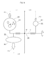
すなわち、この実施形態では、遊星歯車部材103は、図6A及び図6Bに示すように、遊星歯車131と遊星軸132で構成されており、遊星軸132の一端に設けられる作用部105にはノズル支持体600が取り付けられる。この遊星歯車部材103は、図13に示すように、モデル化できる。図13中、c2は遊星歯車部材103の回転軸を、M1は作用部105に連結されるノズル支持体600に相当する質量体を、M2は第1カウンターウェイト145に相当する質量体を、M3は第1バランサー146に相当する質量体をそれぞれ示している。
≪Balance of planetary gear member 103≫
That is, in this embodiment, the planetary gear member 103 is composed of a planetary gear 131 and a planetary shaft 132 as shown in FIGS. 6A and 6B, and the action portion 105 provided at one end of the planetary shaft 132 has a nozzle. A support 600 is attached. This planetary gear member 103 can be modeled as shown in FIG. In FIG. 13, c2 is a rotation shaft of the planetary gear member 103, M1 is a mass body corresponding to the nozzle support 600 connected to the action portion 105, M2 is a mass body corresponding to the first counterweight 145, M3 Indicates mass bodies corresponding to the first balancer 146, respectively.

図13に示すモデルにおいて、遊星歯車部材103が回転した場合に、質量体M1(動作部材)に作用する遠心力をF1、質量体M2(第1カウンターウェイト145)に作用する遠心力をF2、質量体M3(第1バランサー146)に作用する遠心力をF3とする。この遊星歯車部材103は、遠心力F1と、遠心力F2と、遠心力F3を釣り合わせている(F1+F2+F3=0(F1、F2、F3はベクトル量))。   In the model shown in FIG. 13, when the planetary gear member 103 rotates, the centrifugal force acting on the mass body M1 (operation member) is F1, and the centrifugal force acting on the mass body M2 (first counterweight 145) is F2. The centrifugal force acting on the mass body M3 (first balancer 146) is defined as F3. This planetary gear member 103 balances centrifugal force F1, centrifugal force F2, and centrifugal force F3 (F1 + F2 + F3 = 0 (F1, F2, and F3 are vector quantities)).

この場合、F1、F2、F3はそれぞれ「遠心力=質量×半径×(角速度)」の式で算出することができ、遠心力F1、F2、F3の方向は回転軸c2に対して径方向外向きに作用する。(角速度)は、各項に共通しているので除することができ、F1、F2、F3の各項の大きさは、質量×半径に置き換えることができる。さらに、この実施形態では、図6A及び図6Bに示すように、遊星歯車部材103の回転軸c2の軸周りにおいて、ノズル支持体600が取り付けられる作用部105と第1バランサー146とは、第1カウンターウェイト145に対して周方向において180°ずらして配設されている。このため、質量体M1(動作部材)に作用する遠心力F1と質量体M3(第1バランサー146)に作用する遠心力F3は、質量体M2(第1カウンターウェイト145)に作用する遠心力F2に対して常に方向が反対になる。従って、この実施形態では、質量体M1(動作部材)の質量をm1、半径距離をA1とし、質量体M2(第1カウンターウェイト145)の質量をm2、半径距離をA2とし、質量体M3(第1バランサー146)の質量をm3、半径距離をA3とした場合に、F1+F2+F3=0(F1、F2、F3はベクトル量)は、(m1×A1+m3×A3)−(m2×A2)=0となる。このように、遊星歯車部材103は、作用部105にノズル支持体600が取り付けられた状態で回転した場合に、遊星歯車部材103に作用する遠心力が釣り合っている。In this case, F1, F2, and F3 can each be calculated by the formula “centrifugal force = mass × radius × (angular velocity) 2 ”, and the directions of the centrifugal forces F1, F2, and F3 are radial with respect to the rotation axis c2. Acts outward. (Angular velocity) 2 can be removed because it is common to each term, and the size of each term of F1, F2, and F3 can be replaced by mass × radius. Further, in this embodiment, as shown in FIGS. 6A and 6B, the action portion 105 to which the nozzle support 600 is attached and the first balancer 146 around the rotation axis c <b> 2 of the planetary gear member 103 are the first balancer 146. The counterweight 145 is disposed 180 ° shifted in the circumferential direction. Therefore, the centrifugal force F1 acting on the mass body M1 (operation member) and the centrifugal force F3 acting on the mass body M3 (first balancer 146) are the centrifugal force F2 acting on the mass body M2 (first counterweight 145). The direction is always opposite. Therefore, in this embodiment, the mass of the mass body M1 (operation member) is m1, the radial distance is A1, the mass of the mass body M2 (first counterweight 145) is m2, the radial distance is A2, and the mass body M3 ( When the mass of the first balancer 146) is m3 and the radial distance is A3, F1 + F2 + F3 = 0 (F1, F2, and F3 are vector quantities) is (m1 × A1 + m3 × A3) − (m2 × A2) = 0 Become. As described above, when the planetary gear member 103 rotates with the nozzle support 600 attached to the action portion 105, the centrifugal force acting on the planetary gear member 103 is balanced.

さらに、この実施形態では、遊星歯車部材103の回転軸c2上の任意の位置で、遊星歯車部材103に作用する遠心力(F1、F2、F3)のモーメントが釣り合っている。   Furthermore, in this embodiment, the moment of the centrifugal force (F1, F2, F3) acting on the planetary gear member 103 is balanced at an arbitrary position on the rotation axis c2 of the planetary gear member 103.

すなわち、図13に示すように、遊星歯車部材103の回転軸c2上の任意の位置O1から各遠心力F1、F2、F3が作用する位置までの軸方向の距離をそれぞれL1、L2、L3とする。この遊星歯車部材103は、F1×L1+F2×L2+F3×L3=0(F1、F2、F3はベクトル量)になっている。これにより、遊星歯車部材103が回転した場合に、当該回転軸c2上の任意の位置において回転軸c2に直交する軸回りに、遊星歯車部材103を回転させるように作用する力を小さく抑えることができる。   That is, as shown in FIG. 13, the axial distances from the arbitrary position O1 on the rotation axis c2 of the planetary gear member 103 to the positions where the centrifugal forces F1, F2, and F3 act are L1, L2, and L3, respectively. To do. The planetary gear member 103 has F1 × L1 + F2 × L2 + F3 × L3 = 0 (F1, F2, and F3 are vector quantities). Thereby, when the planetary gear member 103 rotates, the force acting to rotate the planetary gear member 103 around an axis orthogonal to the rotation axis c2 at an arbitrary position on the rotation axis c2 can be suppressed to a small value. it can.

この実施形態では、遊星歯車部材103は、第1バランサー146の重さを調整することによって、F1+F2+F3=0(F1、F2、F3はベクトル量)、及び、F1×L1+F2×L2+F3×L3=0(F1、F2、F3はベクトル量)にしている。なお、実際には、各部材については、重さや取り付け位置について製造上の公差が生じる。第1バランサー146の重さを調整する際は、作用部105に、ノズル支持体600に相当するダミーウエイトを配設し、クランク部材104に支持された状態と同様の状態で、遊星歯車部材103を回転自在に支持する。そして、遊星軸132をモータ等で回転させて、遊星歯車部材103に生じる振動が低減されるように、第1バランサー146の重さや取り付け位置を微調整するとよい。   In this embodiment, the planetary gear member 103 adjusts the weight of the first balancer 146 so that F1 + F2 + F3 = 0 (F1, F2, and F3 are vector quantities) and F1 × L1 + F2 × L2 + F3 × L3 = 0 ( F1, F2, and F3 are vector quantities). Actually, for each member, manufacturing tolerances occur in terms of weight and mounting position. When adjusting the weight of the first balancer 146, a dummy weight corresponding to the nozzle support 600 is disposed in the action portion 105, and the planetary gear member 103 is in the same state as that supported by the crank member 104. Is supported rotatably. Then, the planetary shaft 132 is rotated by a motor or the like, and the weight and the mounting position of the first balancer 146 may be finely adjusted so that the vibration generated in the planetary gear member 103 is reduced.

また、第1バランサー146は、遊星歯車部材103の軸方向端部に取り付けられているとよい。この実施形態では、第1バランサー146は、作用部105や第1カウンターウェイト145を取り付ける位置から軸方向に離れた、遊星歯車部材103の軸方向の端部に取り付けられている。この場合、作用部105や第1カウンターウェイト145の近傍位置では、第1バランサー146によって遊星歯車部材103に作用する遠心力のモーメントが大きい。このため、遊星歯車部材103の回転軸c2から同一半径距離に、第1バランサー146を遊星歯車部材103に取り付ける場合、遊星歯車部材103の他の位置に比べて、第1バランサー146を軽くできる。このように、遊星歯車部材103の軸端部に第1バランサー146を取り付けることによって、第1バランサー146を軽くできるから、駆動機構100の全体を軽くすることができる。   Further, the first balancer 146 may be attached to the axial end portion of the planetary gear member 103. In this embodiment, the 1st balancer 146 is attached to the axial direction edge part of the planetary gear member 103 which left | separated from the position which attaches the action part 105 and the 1st counterweight 145 to an axial direction. In this case, the moment of centrifugal force acting on the planetary gear member 103 by the first balancer 146 is large in the vicinity of the action portion 105 and the first counterweight 145. Therefore, when the first balancer 146 is attached to the planetary gear member 103 at the same radial distance from the rotation axis c <b> 2 of the planetary gear member 103, the first balancer 146 can be made lighter than the other positions of the planetary gear member 103. As described above, the first balancer 146 can be lightened by attaching the first balancer 146 to the shaft end portion of the planetary gear member 103, so that the entire drive mechanism 100 can be lightened.

遊星歯車部材103が回転した場合に、遊星歯車部材103に作用する遠心力が釣り合い、かつ、遊星歯車部材103の回転軸上の任意の位置に作用する遠心力のモーメントが釣り合うように調整された一例を図13に示すモデルで示す。例えば、図13に示すモデルにおいて、質量体M1、質量体M2、質量体M3は、それぞれ回転軸c2から重心までの半径距離(A1、A2、A3)が同じである。そして、質量体M2が回転軸c2に取り付けられた位置から質量体M1は左側へS、質量体M3は右側へ2Sの距離にそれぞれ配設されている。この場合、質量体M1が2g、質量体M2が3g、質量体M3が1gである場合に、遊星歯車部材103に作用する遠心力F1、F2、F3が釣り合い、かつ、遊星歯車部材103の回転軸c2上の任意の位置に作用する遠心力F1、F2、F3のモーメントが釣り合う。なお、遊星歯車部材103に作用する遠心力が釣り合い、かつ、遊星歯車部材103の回転軸c2上の任意の位置に作用する遠心力のモーメントが釣り合う例は、この例に限定されない。   When the planetary gear member 103 is rotated, the centrifugal force acting on the planetary gear member 103 is balanced, and the moment of the centrifugal force acting on an arbitrary position on the rotation axis of the planetary gear member 103 is balanced. An example is shown in the model shown in FIG. For example, in the model shown in FIG. 13, the mass bodies M1, M2, and M3 have the same radial distance (A1, A2, A3) from the rotation axis c2 to the center of gravity. The mass body M1 is disposed on the left side from the position where the mass body M2 is attached to the rotation shaft c2, and the mass body M3 is disposed on the right side at a distance of 2S. In this case, when the mass body M1 is 2 g, the mass body M2 is 3 g, and the mass body M3 is 1 g, the centrifugal forces F1, F2, and F3 acting on the planetary gear member 103 are balanced, and the planetary gear member 103 rotates. The moments of centrifugal forces F1, F2, and F3 acting on an arbitrary position on the axis c2 are balanced. An example in which the centrifugal force acting on the planetary gear member 103 is balanced and the moment of the centrifugal force acting on an arbitrary position on the rotation axis c2 of the planetary gear member 103 is balanced is not limited to this example.

≪クランク部材104のバランス≫
このクランク部材104は、クランク部材104に作用する遠心力が釣り合い、かつ、クランク部材104の回転軸c1上の任意の位置に作用する遠心力のモーメントが釣り合う。この駆動機構100は、図14に示すように、モデル化できる。図14中、c1はクランク部材104の回転軸を、M11は遊星歯車部材103に相当する質量体を、M12は第2カウンターウェイト161に相当する質量体を、M13は第2バランサー162に相当する質量体をそれぞれ示している。
<< Balance of crank member 104 >>
The crank member 104 balances the centrifugal force acting on the crank member 104 and the moment of the centrifugal force acting on an arbitrary position on the rotation shaft c1 of the crank member 104. The drive mechanism 100 can be modeled as shown in FIG. In FIG. 14, c1 is the rotation shaft of the crank member 104, M11 is a mass body corresponding to the planetary gear member 103, M12 is a mass body corresponding to the second counterweight 161, and M13 is equivalent to the second balancer 162. Each mass is shown.

図14に示すモデルにおいて、クランク部材104が回転した場合に、質量体M11(遊星歯車103)に作用する遠心力をF11、質量体M12(第2カウンターウェイト161)に作用する遠心力をF12、質量体M13(第2バランサー162)に作用する遠心力をF13とする。このクランク部材104は、遠心力F11と、遠心力F12と、遠心力F13を釣り合わせている(F11+F12+F13=0(F11、F12、F13はベクトル量))。   In the model shown in FIG. 14, when the crank member 104 rotates, the centrifugal force acting on the mass body M11 (planetary gear 103) is F11, and the centrifugal force acting on the mass body M12 (second counterweight 161) is F12, The centrifugal force acting on the mass body M13 (second balancer 162) is defined as F13. This crank member 104 balances centrifugal force F11, centrifugal force F12, and centrifugal force F13 (F11 + F12 + F13 = 0 (F11, F12, and F13 are vector quantities)).

さらに、この実施形態では、クランク部材104の回転軸c1上の任意の位置で、クランク部材104に作用する遠心力(F11、F12、F13)のモーメントが釣り合っている。   Further, in this embodiment, the moment of the centrifugal force (F11, F12, F13) acting on the crank member 104 is balanced at an arbitrary position on the rotation axis c1 of the crank member 104.

すなわち、図14に示すように、クランク部材104の回転軸c1上の任意の位置O2から各遠心力F11、F12、F13が作用する位置までの軸方向の距離をそれぞれL11、L12、L13とする。このクランク部材104は、F11×L11+F12×L12+F13×L13=0(F11、F12、F13はベクトル量)になっている。これにより、クランク部材104が回転した場合に、当該回転軸c1上の任意の位置において回転軸c1に直交する軸回りに、クランク部材104を回転させるように作用する力を小さく抑えることができる。   That is, as shown in FIG. 14, the axial distances from the arbitrary position O2 on the rotation axis c1 of the crank member 104 to the positions where the centrifugal forces F11, F12, and F13 act are L11, L12, and L13, respectively. . The crank member 104 has F11 × L11 + F12 × L12 + F13 × L13 = 0 (F11, F12, and F13 are vector quantities). As a result, when the crank member 104 rotates, the force acting to rotate the crank member 104 around an axis orthogonal to the rotation axis c1 at an arbitrary position on the rotation axis c1 can be kept small.

この実施形態では、クランク部材104は、第2バランサー162の重さを調整することによって、F11+F12+F13=0(F11、F12、F13はベクトル量)、及び、F11×L11+F12×L12+F13×L13=0(F11、F12、F13はベクトル量)にしている。なお、実際には、各部材については、重さや取り付け位置について製造上の公差が生じる。第2バランサー162の重さを調整する際は、クランク部材104に遊星歯車部材103に相当するダミーウエイトを配設し、クランクケース101に支持された状態と同様の状態で、クランク部材104を回転自在に支持する。そして、クランク部材104をモータ等で回転させて、クランク部材104に生じる振動が低減されるように、第2バランサー162の重さや取り付け位置を微調整するとよい。   In this embodiment, the crank member 104 adjusts the weight of the second balancer 162 so that F11 + F12 + F13 = 0 (F11, F12, and F13 are vector quantities) and F11 × L11 + F12 × L12 + F13 × L13 = 0 (F11). F12 and F13 are vector quantities). Actually, for each member, manufacturing tolerances occur in terms of weight and mounting position. When adjusting the weight of the second balancer 162, a dummy weight corresponding to the planetary gear member 103 is disposed on the crank member 104, and the crank member 104 is rotated in the same state as that supported by the crankcase 101. Support freely. Then, the weight and the mounting position of the second balancer 162 may be finely adjusted so that the crank member 104 is rotated by a motor or the like, and vibration generated in the crank member 104 is reduced.

また、この実施形態では、第2バランサー162は、プーリ159に取り付けられている。このプーリ159は、クランク部材104の回転軸c1から離れているので、第2バランサー162の重さを軽くしても作用する遠心力が大きくなる。このため、より軽い第2バランサー162によって、クランク部材104に作用する遠心力が釣り合い、かつ、クランク部材104の回転軸c1上の任意の位置に作用する遠心力のモーメントを釣り合わせることができる。   In this embodiment, the second balancer 162 is attached to the pulley 159. Since the pulley 159 is separated from the rotation axis c1 of the crank member 104, the centrifugal force that acts even when the weight of the second balancer 162 is reduced increases. For this reason, the lighter second balancer 162 can balance the centrifugal force acting on the crank member 104 and balance the moment of the centrifugal force acting on an arbitrary position on the rotation axis c1 of the crank member 104.

上述したように、この駆動機構100は、クランク部材104が回転すると、遊星歯車部材103は自転及び公転する。かかる駆動機構100では、振動を完全に抑えることは極めて難しい。しかしながら、この駆動機構100は、上述したように遊星歯車部材103に作用する遠心力、および、遊星歯車部材103の回転軸c2上の任意の位置に作用する遠心力のモーメントが釣り合っている(釣り合うように調整されている)。さらに、クランク部材104に作用する遠心力、及び、クランク部材104の回転軸c1上の任意の位置に作用する遠心力のモーメントが釣り合っている(釣り合うように調整されている)。このため、遊星歯車部材103の回転軸c2およびクランク部材104の回転軸c1に偏った荷重が作用するのを小さく抑えることができる。これにより、遊星歯車部材103の自転および公転に伴って駆動機構100に生じる振動を極めて小さくすることができる。これによって、ノズル支持体600の旋回速度を格段に速くすることができる。   As described above, in the drive mechanism 100, when the crank member 104 rotates, the planetary gear member 103 rotates and revolves. With such a drive mechanism 100, it is extremely difficult to completely suppress vibration. However, in the drive mechanism 100, the centrifugal force acting on the planetary gear member 103 as described above and the moment of the centrifugal force acting on an arbitrary position on the rotation axis c2 of the planetary gear member 103 are balanced (balanced). Have been adjusted). Further, the centrifugal force acting on the crank member 104 and the moment of the centrifugal force acting on an arbitrary position on the rotation axis c1 of the crank member 104 are balanced (adjusted so as to be balanced). For this reason, it is possible to suppress a biased load from acting on the rotation shaft c2 of the planetary gear member 103 and the rotation shaft c1 of the crank member 104. Thereby, the vibration which arises in the drive mechanism 100 with rotation and revolution of the planetary gear member 103 can be made extremely small. Thereby, the turning speed of the nozzle support 600 can be remarkably increased.

なお、第1バランサー146や第2バランサー162は、それぞれ重さが異なるものに交換可能に取り付けられているとよい。また、第1バランサー146や第2バランサー162は、取付位置を変更可能に取り付けられているとよい。これによって、第1バランサー146と第2バランサー162の重さや取り付け位置を微調整することが可能になる。例えば、第1バランサー146は、遊星歯車部材103の回転軸c2に対して径方向や軸方向に取り付け位置が変更できるようにしてもよい。これによって、遊星歯車部材103に作用する遠心力を釣り合わせ、かつ、遊星歯車部材103の回転軸c2上の任意の位置に作用する遠心力のモーメントを釣り合わせる調整が容易になる。また、第2バランサー162は、クランク部材104の回転軸c1に対して径方向や軸方向に取り付け位置が変更できるようにしてもよい。これによって、クランク部材104に作用する遠心力を釣り合わせ、かつ、クランク部材104の回転軸上の任意の位置に作用する遠心力のモーメントを釣り合わせる調整が容易になる。   In addition, the 1st balancer 146 and the 2nd balancer 162 are good to be attached so that replacement | exchange is possible in the thing from which weight differs, respectively. Moreover, the 1st balancer 146 and the 2nd balancer 162 are good to be attached so that an attachment position can be changed. This makes it possible to finely adjust the weights and attachment positions of the first balancer 146 and the second balancer 162. For example, the mounting position of the first balancer 146 may be changed in the radial direction or the axial direction with respect to the rotation axis c <b> 2 of the planetary gear member 103. Accordingly, it is easy to balance the centrifugal force acting on the planetary gear member 103 and balance the moment of the centrifugal force acting on an arbitrary position on the rotation axis c <b> 2 of the planetary gear member 103. Further, the second balancer 162 may be configured such that the attachment position can be changed in the radial direction or the axial direction with respect to the rotation axis c1 of the crank member 104. Accordingly, it is easy to balance the centrifugal force acting on the crank member 104 and balance the moment of the centrifugal force acting on an arbitrary position on the rotation shaft of the crank member 104.

≪ケーシング700≫
次にケーシング700を説明する。
ケーシング700は、図3及び図4に示すように、ノズル支持体600を収容する部材である。この巻線機1000は、上述したようにノズル支持体600が旋回するが、ノズル支持体600がケーシング700で覆われているので、安全性を確保することができる。また、ノズル支持体600を支持する駆動機構100に外から異物が進入するのを防止できる。
<< Case 700 >>
Next, the casing 700 will be described.
As shown in FIGS. 3 and 4, the casing 700 is a member that accommodates the nozzle support 600. In the winding machine 1000, the nozzle support 600 rotates as described above. However, since the nozzle support 600 is covered with the casing 700, safety can be ensured. In addition, foreign matter can be prevented from entering the drive mechanism 100 that supports the nozzle support 600 from the outside.

≪ケーシング700の構造≫
この実施形態では、ケーシング700は、図4に示すように、クランク部材104の軸線方向の前後に分離可能な2つのケース体701、702を嵌め合わせた構造を備えている。ケーシング700内には、ノズル支持体600が旋回する矩形の空間712が形成されている。図3は、ケース体701(蓋)を取り外した状態を示している。図4は、巻線機の縦断側面図であり、図3中のIV−IV断面矢視図である。
<< Structure of casing 700 >>
In this embodiment, as shown in FIG. 4, the casing 700 has a structure in which two case bodies 701 and 702 that are separable in the axial direction of the crank member 104 are fitted. A rectangular space 712 in which the nozzle support 600 turns is formed in the casing 700. FIG. 3 shows a state where the case body 701 (lid) is removed. FIG. 4 is a longitudinal side view of the winding machine, and is a sectional view taken along the line IV-IV in FIG. 3.

この実施形態では、図3及び図4に示すように、ケーシング700の中央部にノズル支持体600に支持されたノズル501〜503が旋回するノズル旋回空間710を有している。この実施形態では、ケーシング700は、ノズル旋回空間710を形成する当該筒状の仕切り711を有している。図4に示すように、ノズル支持体600は、仕切り711に形成されたスリット状の隙間720に装着されている。当該スリット状の隙間720にはシール730が配設されている。   In this embodiment, as shown in FIGS. 3 and 4, a nozzle turning space 710 in which the nozzles 501 to 503 supported by the nozzle support 600 are turned is provided at the center of the casing 700. In this embodiment, the casing 700 has the cylindrical partition 711 that forms the nozzle turning space 710. As shown in FIG. 4, the nozzle support 600 is attached to a slit-like gap 720 formed in the partition 711. A seal 730 is disposed in the slit-like gap 720.

この実施形態では、図4に示すように、ケース体701は、中央部に、ノズル旋回空間710を形成する円形の穴が形成されており、その周縁部にケーシング700内に突出した第1の仕切り711aが設けられている。ケース体702は、中央部に、ノズル旋回空間710を形成する円形の穴が形成されており、その周縁部にケーシング700内に突出した第2の仕切り711bが設けられている。ケース体701側の第1の仕切り711aの端面と、ケース体702側の第2の仕切り711bの端面とが対向しており、当該第1の仕切り711aの端面と、第2の仕切り711bの端面との間にスリット状の隙間720が形成されている。ノズル支持体600は、プレート状の部材であり、当該スリット状の隙間720に装着されている。   In this embodiment, as shown in FIG. 4, the case body 701 is formed with a circular hole forming the nozzle swirl space 710 at the center, and the first portion protruding into the casing 700 at the peripheral edge. A partition 711a is provided. The case body 702 is formed with a circular hole forming the nozzle swirl space 710 at the center, and a second partition 711b protruding into the casing 700 is provided at the peripheral edge thereof. The end surface of the first partition 711a on the case body 701 side and the end surface of the second partition 711b on the case body 702 side face each other, and the end surface of the first partition 711a and the end surface of the second partition 711b A slit-like gap 720 is formed between the two. The nozzle support 600 is a plate-like member and is attached to the slit-like gap 720.

また、この実施形態では、図3に示すように、筒状のノズル旋回空間710を仕切る仕切り711を挟んで両側に駆動機構100が装着されている。具体的には、ケース体702に仕切り711bを挟んで両側に開口715、716が形成されている。当該開口715、716に駆動機構100が装着されている。駆動機構100は、作用部105をケーシング700内に向けて、クランクケース101を開口715、716に装着している。左右の駆動機構100は、タイミングベルト201で同期しており、左右の駆動機構100の作用部105は、それぞれ同期して同様の楕円軌道Aで旋回する。ノズル支持体600は、当該駆動機構100の作用部105にそれぞれ連結されている。   In this embodiment, as shown in FIG. 3, the drive mechanisms 100 are mounted on both sides of a partition 711 that partitions the cylindrical nozzle turning space 710. Specifically, openings 715 and 716 are formed on both sides of the case body 702 across the partition 711b. The drive mechanism 100 is attached to the openings 715 and 716. The drive mechanism 100 has the crankcase 101 mounted in the openings 715 and 716 with the action portion 105 facing the casing 700. The left and right drive mechanisms 100 are synchronized with a timing belt 201, and the action portions 105 of the left and right drive mechanisms 100 are rotated in the same elliptical orbit A in synchronization with each other. The nozzle support 600 is connected to the action part 105 of the drive mechanism 100.

この実施形態では、ケーシング700は、ノズル支持体600が旋回する支持体旋回空間712の気密性が確保されており、当該空間712は潤滑オイルが供給されている。この実施形態では、かかる潤滑オイルがノズル旋回空間710に漏れないように、当該スリット状の隙間720にシール730が配設されている。   In this embodiment, the casing 700 ensures the airtightness of the support body turning space 712 in which the nozzle support body 600 turns, and the space 712 is supplied with lubricating oil. In this embodiment, a seal 730 is provided in the slit-shaped gap 720 so that the lubricating oil does not leak into the nozzle swirl space 710.

すなわち、この実施形態では、ケーシング700は、ノズル支持体600に支持されたノズル501〜503が旋回するノズル旋回空間710と、ノズル支持体600が旋回する支持体旋回空間712とを有している。そして、ノズル旋回空間710と支持体旋回空間712とを仕切るシール730とを備えている。かかるシール730によって支持体旋回空間712内の潤滑オイルがノズル旋回空間710に漏れるのを防止できる。これにより、ノズル旋回空間710を挿通する線材がオイルで汚れるのを抑制できる。   That is, in this embodiment, the casing 700 has a nozzle turning space 710 in which the nozzles 501 to 503 supported by the nozzle support 600 are turned, and a support turning space 712 in which the nozzle support 600 is turned. . And the seal | sticker 730 which partitions off the nozzle turning space 710 and the support body turning space 712 is provided. Such a seal 730 can prevent the lubricating oil in the support turning space 712 from leaking into the nozzle turning space 710. Thereby, it can suppress that the wire which penetrates the nozzle turning space 710 gets dirty with oil.

≪シール730の構造≫
以下、この実施形態における、シール730の構造を説明する。
この実施形態では、シール730は、図15に示すように、スリット状の隙間720の端面に内外に2重のシールが構成されている。外側に配設された第1シール731は、スリット状の隙間720の端面に形成された装着溝722に装着され、ノズル支持体600の表面に接触する。内側に配設された第2シール732は、弾性体としてのばね742の作用によってノズル支持体600の表面に強制的に押し当てられる。また、この実施形態では、第2シール732は内側から外側に向かうにつれて徐々にノズル支持体600の表面に向けて突出したテーパ形状を有している。
<< Structure of seal 730 >>
Hereinafter, the structure of the seal 730 in this embodiment will be described.
In this embodiment, as shown in FIG. 15, the seal 730 is formed with a double seal inside and outside on the end face of the slit-like gap 720. The first seal 731 disposed outside is mounted in a mounting groove 722 formed on the end surface of the slit-shaped gap 720 and contacts the surface of the nozzle support 600. The second seal 732 disposed on the inside is forcibly pressed against the surface of the nozzle support 600 by the action of a spring 742 as an elastic body. In this embodiment, the second seal 732 has a tapered shape that gradually protrudes toward the surface of the nozzle support 600 from the inside toward the outside.

また、この実施形態では、筒状の挿通空間の径方向において第2シールよりも外側に向かうドレン通路を有する。当該ドレン通路は、第1シール731の一部に溝を設けて形成してもよいし、第2シール732を装着する装着溝に、ドレン穴を形成してもよい。   Moreover, in this embodiment, it has a drain channel | path toward the outer side rather than a 2nd seal in the radial direction of a cylindrical insertion space. The drain passage may be formed by providing a groove in a part of the first seal 731, or a drain hole may be formed in a mounting groove for mounting the second seal 732.

この場合、シールは二重に構成されており、外側に配設された第1シール731によって、支持体旋回空間712中のオイル成分を概ね遮断することができる。さらに第1シール731を乗り越えたオイル成分についても、ノズル支持体600の表面に強制的に押し当てられる第2シール732によって遮断することができる。   In this case, the seal is doubled, and the oil component in the support body swirling space 712 can be substantially blocked by the first seal 731 disposed outside. Furthermore, the oil component that has passed over the first seal 731 can also be blocked by the second seal 732 that is forcibly pressed against the surface of the nozzle support 600.

さらに、第2シール732は、ノズル支持体600に対向する面が内側から外側に向かうにつれて、徐々にノズル支持体600に近づくように突出したテーパ形状を有している。第2シール732は、旋回するノズル支持体600の表面に、外側の頂部が確実に押し当たる。かかる第2シール732によってオイル成分をより確実に遮断することができる。   Further, the second seal 732 has a tapered shape that gradually protrudes so as to approach the nozzle support 600 as the surface facing the nozzle support 600 moves from the inside to the outside. As for the 2nd seal | sticker 732, the outer top part presses against the surface of the nozzle support body 600 which turns. The oil component can be more reliably blocked by the second seal 732.

次に、他の実施形態に係る巻線機1000Aを示す。
この巻線機1000Aは、図16及び図17に示すように、主にケーシング700Aの構造が異なっている。また、潤滑オイルを供給する経路の一例についてもこの実施形態に基づいて説明する。
Next, a winding machine 1000A according to another embodiment is shown.
As shown in FIGS. 16 and 17, the winding machine 1000A is mainly different in the structure of a casing 700A. An example of a route for supplying the lubricating oil will also be described based on this embodiment.

このケーシング700Aは、図17に示すように、第1ケース体701A(蓋)と、第2ケース体702Aで構成されている。第1ケース体701Aと第2ケース体702Aは、図18と図19に示すように、矩形の鋼板であり、それぞれ中央部にノズル501〜503が旋回するノズル旋回空間710を形成する穴771a、771bが形成されている。   As shown in FIG. 17, the casing 700 </ b> A includes a first case body 701 </ b> A (lid) and a second case body 702 </ b> A. As shown in FIGS. 18 and 19, the first case body 701A and the second case body 702A are rectangular steel plates, each having a hole 771a that forms a nozzle swirl space 710 in which the nozzles 501 to 503 swirl at the center. 771b is formed.

図18及び図19に示すように、第1ケース体701Aと第2ケース体702Aは、それぞれ当該穴771a、771bの周囲にシール730が配設されている。シール730の外側には、旋回するノズル支持体600を滑り支承する滑り支持部780が設けられている。また、第2ケース体702Aは、図17および図19に示すように、ノズル支持体600が旋回する支持体旋回空間712及び駆動機構100が装着される領域を囲むように窪み790(図19参照)が形成されている。そして、当該窪み790の周りにガスケット810が装着されている。また、駆動機構100は、ノズル旋回空間710の両側に配設されている。この実施形態では、第2ケース体702Aには、滑り支持部780の外側に、駆動機構100を装着する開口715、716が形成されている。また、第1ケース体701Aには、駆動機構100の作用部105が旋回する領域に窪み791、792が形成されている。   As shown in FIGS. 18 and 19, the first case body 701A and the second case body 702A are provided with seals 730 around the holes 771a and 771b, respectively. On the outside of the seal 730, a sliding support portion 780 for slidingly supporting the swiveling nozzle support body 600 is provided. Further, as shown in FIGS. 17 and 19, the second case body 702A has a recess 790 (see FIG. 19) so as to surround a support turning space 712 in which the nozzle support 600 turns and a region where the drive mechanism 100 is mounted. ) Is formed. A gasket 810 is attached around the recess 790. The drive mechanism 100 is disposed on both sides of the nozzle turning space 710. In this embodiment, openings 715 and 716 for mounting the drive mechanism 100 are formed on the outer side of the sliding support portion 780 in the second case body 702A. Further, in the first case body 701A, depressions 791 and 792 are formed in a region where the action portion 105 of the drive mechanism 100 turns.

このケーシング700Aは、図16に示すように、上述した第2ケース体702Aに形成された開口715、716にそれぞれ駆動機構100が装着されている。駆動機構100は、図17に示すように、作用部105を、当該開口715、716から第1ケース体701Aと第2ケース体702Aの間に形成される空間に向け、クランクケース101を当該開口715、716に装着している。2つの駆動機構100は、作用部105が同様の楕円軌道Aで同期して旋回するようにタイミングベルト201が装着されている。   As shown in FIG. 16, the casing 700 </ b> A is provided with the driving mechanism 100 in the openings 715 and 716 formed in the second case body 702 </ b> A described above. As shown in FIG. 17, the drive mechanism 100 directs the action portion 105 from the openings 715 and 716 to a space formed between the first case body 701A and the second case body 702A and directs the crankcase 101 to the opening. 715 and 716. The timing belt 201 is mounted on the two drive mechanisms 100 so that the action portion 105 rotates synchronously on the same elliptical orbit A.

ノズル支持体600は、略ひし形のプレート状の部材であり、支持体旋回空間712を形成する第2ケース体702Aの窪みに装着されている。上述した2つの駆動機構100の作用部105は、当該ノズル支持体600の離れた2箇所の位置に連結されている。   The nozzle support body 600 is a substantially diamond-shaped plate-like member, and is mounted in a recess of the second case body 702A that forms the support body turning space 712. The action portions 105 of the two drive mechanisms 100 described above are connected to two positions away from the nozzle support 600.

ケーシング700Aは、図16に示すように、第2ケース体702Aに駆動機構100及びノズル支持体600が取り付けられた状態で、図17に示すように、第1ケース体701A(蓋)が取り付けられる。第2ケース体702Aに装着されたガスケット810は、図17に示すように、第1ケース体701Aに押し当てられる。当該ガスケット810によって、支持体旋回空間712の気密性が確保されている。   As shown in FIG. 16, the casing 700 </ b> A is attached with the first case body 701 </ b> A (lid) as shown in FIG. 17 in a state where the drive mechanism 100 and the nozzle support body 600 are attached to the second case body 702 </ b> A. . The gasket 810 attached to the second case body 702A is pressed against the first case body 701A as shown in FIG. The gasket 810 ensures the airtightness of the support swirl space 712.

次に、ノズル旋回空間710の周りに構築されるシール730について説明する。   Next, the seal 730 constructed around the nozzle turning space 710 will be described.

この実施形態では、図20に示すように、第1ケース体701Aと第2ケース体702Aに、ノズル旋回空間710を形成する穴771aと771bの周りにシール材773を装着する溝772が形成されている。シール材773は、環状のシール材であり、内周側面にはOリング775が装着されている。さらに、この実施形態では、シール材773と溝772の底部との間に、弾性部材としてのばね774が圧縮された状態で配設されており、当該ばね774によってシール材773がノズル支持体600の表面に押し当てられている。なお、ここで、弾性部材としてのばね774は、コイルスプリングを図示しているが、環状のシール材773をノズル支持体600の表面に確実に押し当てる機能を奏すればよく、コイルスプリングに限らず、例えば、種々のスプリングワッシャーを装着してもよい。   In this embodiment, as shown in FIG. 20, the first case body 701A and the second case body 702A are formed with grooves 772 for mounting the sealing material 773 around the holes 771a and 771b forming the nozzle turning space 710. ing. The sealing material 773 is an annular sealing material, and an O-ring 775 is attached to the inner peripheral side surface. Further, in this embodiment, a spring 774 as an elastic member is disposed between the seal material 773 and the bottom of the groove 772 in a compressed state, and the seal material 773 is moved by the spring 774 to the nozzle support 600. Is pressed against the surface. Here, although the spring 774 as the elastic member is illustrated as a coil spring, the spring 774 is not limited to the coil spring as long as it has a function of reliably pressing the annular seal member 773 against the surface of the nozzle support 600. For example, various spring washers may be mounted.

また、環状のシール材773は、ノズル支持体600に対向する面773aが、環状のシール材773の径方向内側から外側に向かうにつれて、徐々にノズル支持体600に近づくように突出したテーパ形状を有している。   Further, the annular sealing material 773 has a tapered shape in which the surface 773a facing the nozzle support 600 gradually protrudes so as to approach the nozzle support 600 as it goes from the radially inner side to the outside of the annular seal material 773. Have.

また、この実施形態では、ケーシング700Aは、ノズル支持体600の旋回を支持する滑り支持部780を備えている。この実施形態では、上述したスリット状の隙間720の両側に、縦長の溝781が形成されており、当該溝781に滑り材782が装着されている。   In this embodiment, the casing 700 </ b> A includes a sliding support portion 780 that supports the turning of the nozzle support 600. In this embodiment, vertically long grooves 781 are formed on both sides of the above-described slit-like gap 720, and a sliding material 782 is attached to the grooves 781.

このように、この実施形態では、シール730によって、ノズル旋回空間710と支持体旋回空間712とが仕切られている。かかるシール730によって、ノズル旋回空間710に潤滑オイルが漏れるのが防止されている。また、この実施形態では、シール730はノズル旋回空間710を囲むように配設され、ノズル支持体600の表面に押し当てられた環状のシール材773を備えている。そして、環状のシール材773は、図21に示すように、ノズル支持体600に対向する面773aが内側から外側に向かうにつれて、徐々にノズル支持体600に近づくように突出したテーパ形状を有している。このため、シール材773のテーパ形状の頂部が、旋回するノズル支持体600の表面に当接し、ノズル支持体600の表面に付着した潤滑オイルを削ぐように除去することができる。これにより、ノズル旋回空間710に潤滑オイルが漏れるのを抑止できる。また、ケーシング700Aは、ノズル支持体600の旋回を支持する滑り支持部780を備えている。このため、ノズル支持体600のばたつきを抑えることができる。   Thus, in this embodiment, the nozzle swirl space 710 and the support swirl space 712 are partitioned by the seal 730. The seal 730 prevents the lubricating oil from leaking into the nozzle turning space 710. In this embodiment, the seal 730 is disposed so as to surround the nozzle turning space 710, and includes an annular seal member 773 pressed against the surface of the nozzle support 600. As shown in FIG. 21, the annular sealing material 773 has a tapered shape that gradually protrudes toward the nozzle support 600 as the surface 773 a facing the nozzle support 600 moves from the inside to the outside. ing. For this reason, the taper-shaped top part of the sealing material 773 abuts on the surface of the swiveling nozzle support 600, and the lubricating oil adhering to the surface of the nozzle support 600 can be removed so as to be scraped off. Thereby, it can suppress that lubricating oil leaks into the nozzle turning space 710. Further, the casing 700 </ b> A includes a sliding support portion 780 that supports the turning of the nozzle support 600. For this reason, flapping of the nozzle support 600 can be suppressed.

特に、この実施形態では、滑り支持部780は、ノズル旋回空間710を仕切るシール730の周りに形成されている。プレート状のノズル支持体600は、ノズル旋回空間710を仕切るシール730間に形成されたスリット状の隙間720に装着されている。滑り支持部780は、当該シール730の周りに形成され、当該シール730の周りでノズル支持体600の平坦度を確保している。これによって、ノズル支持体600を適切に当該スリット状の隙間720へ装着することができるともに、ノズル支持体600が旋回する際も、ばたつきや引っ掛かることなく、スムーズに旋回することができる。   In particular, in this embodiment, the sliding support portion 780 is formed around the seal 730 that partitions the nozzle turning space 710. The plate-like nozzle support 600 is mounted in a slit-like gap 720 formed between the seals 730 that partition the nozzle turning space 710. The sliding support portion 780 is formed around the seal 730 and ensures the flatness of the nozzle support 600 around the seal 730. As a result, the nozzle support 600 can be properly mounted in the slit-shaped gap 720, and when the nozzle support 600 is turned, it can be turned smoothly without fluttering or being caught.

この実施形態では、ノズル支持体600には、アルミ合金からなる鋼板が用いられており、表面には硬質アルマイト処理が施されている。なお、ノズル支持体600は、旋回させるため、軽量であることが望ましい。この実施形態では、アルミ合金からなる鋼板を用いているが、これに限らず、所用の強度を備えた種々の板材を用いることができ、例えば、カーボン製の板材を用いることができる。
また、この実施形態では、シール材773及び滑り材782には、例えば、燐青銅系の合金材料を用いている。かかる合金は、かかるノズル支持体600の表面に対して滑りがよく、かつ、ノズル支持体600の表面に付着した油を削ぎ落とすのに適した所用の硬度を有している。なお、シール材773及び滑り材782に用いられる材料は、燐青銅系の合金材料に限らない。滑り材782には、ノズル支持体600の表面に対して滑りがよい材料を用いるとよい。また、シール材773には、ノズル支持体600の表面に対して滑りがよく、かつ、ノズル支持体600の表面に付着した油を削ぐのに適した所用の硬度を有している種々の材料を用いることができる。
In this embodiment, a steel plate made of an aluminum alloy is used for the nozzle support 600, and the surface is subjected to hard alumite treatment. In addition, since the nozzle support body 600 turns, it is desirable that it is lightweight. In this embodiment, although the steel plate which consists of aluminum alloys is used, not only this but the various board | plate material provided with the required intensity | strength can be used, for example, the board | plate material made from carbon can be used.
In this embodiment, for example, a phosphor bronze alloy material is used for the sealing material 773 and the sliding material 782. Such an alloy is slippery with respect to the surface of the nozzle support 600 and has a desired hardness suitable for scraping off oil adhering to the surface of the nozzle support 600. Note that the material used for the sealing material 773 and the sliding material 782 is not limited to a phosphor bronze alloy material. For the sliding material 782, a material that is slippery with respect to the surface of the nozzle support 600 may be used. Further, the sealing material 773 has various materials having good hardness suitable for scraping off oil adhering to the surface of the nozzle support 600 and having good sliding with respect to the surface of the nozzle support 600. Can be used.

シール材773及び滑り材782には、例えば、鋳鉄材、鋼材を用いることができる。また、潤滑オイルの使用を少なくするべく、鋳鉄材、鋼材などの母材にポリテトラフルオロエチレンなどのフッ素樹脂系の材料で表面処理を行ってもよい。さらにポリテトラフルオロエチレンなどのフッ素樹脂系の材料にグラファイトなどを練り込んだ材料を用いても良い。また、ノズル支持体600の表面にも、少なくともシール材773や滑り材782との間に滑りが生じる部位に、ポリテトラフルオロエチレンなどのフッ素樹脂系の材料で表面処理を行ってもよい。   For the sealing material 773 and the sliding material 782, for example, a cast iron material or a steel material can be used. Further, in order to reduce the use of lubricating oil, surface treatment may be performed on a base material such as cast iron or steel with a fluororesin-based material such as polytetrafluoroethylene. Further, a material obtained by kneading graphite or the like into a fluororesin material such as polytetrafluoroethylene may be used. The surface of the nozzle support 600 may also be subjected to a surface treatment with a fluororesin-based material such as polytetrafluoroethylene at least at a site where slip occurs between the sealing material 773 and the sliding material 782.

次に、潤滑オイルを供給する経路を説明する。この実施形態では、潤滑オイルは、図17に示すように、駆動機構100のクランクケース101に形成されたオイル供給穴820から供給される。そして、供給された潤滑オイルは、駆動機構100内の部材間の隙間192や軸受181、183を通してケーシング700A内の支持体旋回空間712に潤滑オイルが供給される。この実施形態では、潤滑オイルは、駆動機構100内については、例えば、クランクケース101の内側面と、クランク部材104の外側面の間の隙間192や、遊星歯車部材103とクランク部材104の間の隙間などを通して、内周太陽歯車102と遊星歯車131が噛み合う部分にも供給されている。
なお、この実施形態では、図17に示すように、駆動機構100は、クランク部材104に遊星歯車部材103を装着する軸受181と軸受182の間にスペーサ190が装着されている。当該スペーサ190にも油路が形成されている。
Next, a route for supplying lubricating oil will be described. In this embodiment, the lubricating oil is supplied from an oil supply hole 820 formed in the crankcase 101 of the drive mechanism 100 as shown in FIG. The supplied lubricating oil is supplied to the support body turning space 712 in the casing 700A through the gap 192 between the members in the drive mechanism 100 and the bearings 181 and 183. In this embodiment, the lubricating oil in the drive mechanism 100 is, for example, a gap 192 between the inner surface of the crankcase 101 and the outer surface of the crank member 104 or between the planetary gear member 103 and the crank member 104. It is also supplied to a portion where the inner peripheral sun gear 102 and the planetary gear 131 mesh with each other through a gap.
In this embodiment, as shown in FIG. 17, in the drive mechanism 100, a spacer 190 is mounted between a bearing 181 that mounts the planetary gear member 103 on the crank member 104 and the bearing 182. An oil path is also formed in the spacer 190.

そして、ケーシング700A内の支持体旋回空間712に供給された潤滑オイルは、駆動機構100の旋回やノズル支持体600の旋回によって、支持体旋回空間712内にオイル雰囲気を形成する。かかるオイル雰囲気によって、ケーシング700Aの支持体旋回空間712内の各部材の表面に潤滑オイルが付着する。また、ケーシング700A内に供給された潤滑オイルは、図16及び図17に示すように、第2ケース体702Aの支持体旋回空間712の下部に形成された排出穴830から排出される。   The lubricating oil supplied to the support body swirl space 712 in the casing 700 </ b> A forms an oil atmosphere in the support body swirl space 712 due to the rotation of the drive mechanism 100 and the swirl of the nozzle support body 600. With such an oil atmosphere, lubricating oil adheres to the surface of each member in the support body swirling space 712 of the casing 700A. Also, as shown in FIGS. 16 and 17, the lubricating oil supplied into the casing 700A is discharged from a discharge hole 830 formed in the lower portion of the support turning space 712 of the second case body 702A.

図示は省略するが、排出穴830から排出された潤滑オイルを回収して、再び駆動機構100に供給する循環装置を設けても良い。   Although illustration is omitted, a circulation device that collects the lubricating oil discharged from the discharge hole 830 and supplies it to the drive mechanism 100 again may be provided.

以上、本発明の一実施形態に係る巻線機1000を説明したが、本発明に係る巻線機1000は、上述した実施形態に限定されない。   As mentioned above, although the winding machine 1000 which concerns on one Embodiment of this invention was demonstrated, the winding machine 1000 which concerns on this invention is not limited to embodiment mentioned above.

また、上述した内周太陽歯車102、遊星歯車部材103、クランクケース101、クランク部材104などの具体的な形状や構造は、種々の変更が可能である。   The specific shapes and structures of the inner sun gear 102, the planetary gear member 103, the crankcase 101, the crank member 104, and the like described above can be variously changed.

例えば、上述した実施形態では、図3に示すように、ノズル支持体600は、両側部620、630(ひし形のノズル支持体600の両側の頂点部分))が、駆動機構100の作用部105にそれぞれ連結されている。本発明は、必ずしもかかる形態に限らない。図示は省略するが、ノズル支持体600の旋回を案内するガイドを設けてもよい。また、ノズル支持体600を駆動機構100の作用部105に連結する位置は3箇所にしてもよい。また、ノズル支持体600を駆動機構100の作用部105に連結する位置は、1箇所にし、他の位置にガイドを設けても良い。   For example, in the above-described embodiment, as shown in FIG. 3, the nozzle support 600 has both side portions 620 and 630 (vertical portions on both sides of the rhombus-shaped nozzle support 600) on the action portion 105 of the drive mechanism 100. Each is connected. The present invention is not necessarily limited to such a form. Although illustration is omitted, a guide for guiding the turning of the nozzle support 600 may be provided. Further, the position where the nozzle support 600 is connected to the action part 105 of the drive mechanism 100 may be three. Further, the position where the nozzle support 600 is connected to the action part 105 of the drive mechanism 100 may be one, and a guide may be provided at another position.

また、図22に示すように、ノズル501〜503を支持するノズル支持体600はひし形である必要はない。
また、図22に示すように楕円軌道Aを補正しても良い。すなわち、本発明に係る巻線機1000Aは、ノズル支持体600の旋回速度を遅くして運転するような用途などでは、例えば、ノズル支持体600を回動させる楕円軌道Aを補正するガイド750を備えてもよい。例えば、楕円の長軸を結ぶ弧の部分で、ノズル支持体600が直線状に動くようにガイド溝751が形成されており、ノズル支持体600に設けたピン752が当該ガイド溝751に係合し、ノズル支持体600が旋回する軌道Bが補正されている。この実施形態では、ノズル支持体600と駆動機構100の作用部105の連結構造についても、当該ノズル支持体600の旋回軌道の補正を許容できるように、スライダ753を設けてもよい。なお、図22に示す形態では、楕円Aの長軸を結ぶ弧の部分で、ノズル支持体600が直線状に動く補正された軌道Bが形成されている。駆動機構100によって、さらに縦長の楕円Aを形成し、楕円Aの長軸を結ぶ弧の部分を直線に近づけるとともに、両端部を補正し、ノズル支持体600が必要以上に縦方向に動かないように、ガイドを設けても良い。
Further, as shown in FIG. 22, the nozzle support 600 that supports the nozzles 501 to 503 does not have to be diamond-shaped.
Further, the elliptical orbit A may be corrected as shown in FIG. That is, the winding machine 1000A according to the present invention includes, for example, a guide 750 that corrects the elliptical orbit A for rotating the nozzle support 600 in an application where the rotation speed of the nozzle support 600 is decreased. You may prepare. For example, a guide groove 751 is formed so that the nozzle support 600 moves linearly at an arc portion connecting the major axes of the ellipses, and a pin 752 provided on the nozzle support 600 is engaged with the guide groove 751. In addition, the trajectory B around which the nozzle support 600 turns is corrected. In this embodiment, a slider 753 may be provided for the connection structure of the nozzle support 600 and the action portion 105 of the drive mechanism 100 so as to allow correction of the turning trajectory of the nozzle support 600. In the form shown in FIG. 22, a corrected trajectory B in which the nozzle support 600 moves linearly is formed at an arc portion connecting the major axes of the ellipse A. The drive mechanism 100 further forms a vertically long ellipse A, the arc portion connecting the long axes of the ellipse A is brought close to a straight line, both ends are corrected, and the nozzle support 600 does not move in the vertical direction more than necessary. In addition, a guide may be provided.

また、上述した実施形態では、作用部105を遊星歯車131のピッチ円103cの内側にずらして配設されている。これによって、作用部105を楕円軌道Aで旋回させているが、図23に示すように、作用部105を遊星歯車131のピッチ円103cの外側にずらして楕円軌道を形成してもよい。このように、作用部105が遊星歯車131のピッチ円103cの外側にずれている場合には、同じ形状の楕円軌道を形成する際に、遊星歯車131や内周太陽歯車102を小さくできる。また、駆動機構100の各部材、例えば、クランク部材104なども小さくできる。このため、駆動機構100に作用する慣性力を小さく抑えることができる。   Further, in the above-described embodiment, the action portion 105 is disposed so as to be shifted to the inside of the pitch circle 103 c of the planetary gear 131. As a result, the action part 105 is swung on the elliptical orbit A. However, as shown in FIG. 23, the action part 105 may be shifted to the outside of the pitch circle 103c of the planetary gear 131 to form an elliptical orbit. Thus, when the action part 105 has shifted | deviated outside the pitch circle 103c of the planetary gear 131, when forming the elliptical orbit of the same shape, the planetary gear 131 and the inner peripheral sun gear 102 can be made small. Further, each member of the drive mechanism 100, for example, the crank member 104 can be reduced. For this reason, the inertia force which acts on the drive mechanism 100 can be suppressed small.

また、駆動機構100の各部材について、特に、クランク部材104など、回転に伴う慣性力が駆動時に生じる部材については、軽量化を図ることが望ましい。例えば、アルミ合金などの軽い材料を用いたり、所要の強度を確保しつつ、肉厚を減らしたりしても良い。   In addition, it is desirable to reduce the weight of each member of the drive mechanism 100, in particular, a member such as the crank member 104 that generates an inertial force associated with rotation during driving. For example, a light material such as an aluminum alloy may be used, or the wall thickness may be reduced while ensuring a required strength.

以上、本発明の一実施形態に係る巻線機について、種々の変形例を例示したが、本発明に係る巻線機は、上述した変形例にも限定されない。   As mentioned above, although the various modifications are illustrated about the winding machine concerning one embodiment of the present invention, the winding machine concerning the present invention is not limited to the modification mentioned above.

100 駆動機構
101 クランクケース
102 内周太陽歯車
103 遊星歯車部材
104 クランク部材
105 作用部
131 遊星歯車
132 遊星軸
145 第1カウンターウェイト
146 第1バランサー
161 第2カウンターウェイト
162 第2バランサー
181〜184 軸受
186 シール
200 モータ
201 タイミングベルト
210 プーリ
501〜503 ノズル
510 線材
600 ノズル支持体
610 中央部
620、630 ノズル支持体の両側部
700、700A ケーシング
710 ノズル旋回空間
712 支持体旋回空間
720 スリット状の隙間
722 装着溝
730 シール
731 第1シール
732 第2シール
750 ガイド
751 ガイド溝
752 ピン
753 スライダ
772 シール材を装着する溝
773 シール材
775 Oリング
780 滑り支持部
810 ガスケット
820 オイル供給穴
830 排出穴
1000、1000A 巻線機
A 楕円軌道
DESCRIPTION OF SYMBOLS 100 Drive mechanism 101 Crank case 102 Inner periphery sun gear 103 Planetary gear member 104 Crank member 105 Action part 131 Planetary gear 132 Planetary shaft 145 1st counterweight 146 1st balancer 161 2nd counterweight 162 2nd balancer 181-184 Bearing 186 Seal 200 Motor 201 Timing belt 210 Pulley 501-503 Nozzle 510 Wire rod 600 Nozzle support 610 Central portion 620, 630 Nozzle support both sides 700, 700A Casing 710 Nozzle swirl space 712 Support swirl space 720 Slit-shaped gap 722 Mounted Groove 730 Seal 731 First seal 732 Second seal 750 Guide 751 Guide groove 752 Pin 753 Slider 772 Groove 773 for attaching a seal material Seal material 775 O-ring 7 80 Sliding support portion 810 Gasket 820 Oil supply hole 830 Discharge hole 1000, 1000A Winding machine A Elliptical track

Claims (12)

線材を繰出すノズルを支持するノズル支持体と、
前記ノズル支持体の離れた少なくとも2箇所の位置にそれぞれ連結され、同じ楕円軌道で同期して旋回する作用部を有する駆動機構と、
を備えた巻線機であって、
前記駆動機構は、
クランクケースと、
前記クランクケースに固定的に配設された内周太陽歯車と、
前記内周太陽歯車に遊星歯車を噛み合わせつつ自転及び公転する遊星歯車部材と、
前記内周太陽歯車の中心線と同軸に回転するように前記クランクケースに配設され、前記遊星歯車部材を自転及び公転可能に支持するクランク部材と
を備え、
前記遊星歯車は、内周太陽歯車のピッチ円直径の2分の1のピッチ円直径を有し、
前記遊星歯車部材は、前記遊星歯車のピッチ円上からずらした位置に前記遊星歯車の自転及び公転に伴って楕円軌道で駆動する作用部を有しており、
前記クランク部材は、軸部材であり、前記クランク部材の片側の端面には、前記遊星歯車部材を装着する装着穴が軸方向に形成されており、
当該装着穴の中心軸は、前記クランク部材の回転軸から遊星歯車のピッチ円の半径の距離だけずれた位置に形成されており、
当該装着穴には、軸受を介在させて、前記遊星歯車部材が回動自在に支持されている、巻線機。
A nozzle support for supporting a nozzle for feeding out the wire,
A drive mechanism connected to at least two positions away from the nozzle support and having an action part that rotates in the same elliptical orbit synchronously;
A winding machine comprising:
The drive mechanism is
A crankcase,
An inner sun gear fixedly disposed on the crankcase;
A planetary gear member that rotates and revolves while meshing a planetary gear with the inner circumferential sun gear;
A crank member disposed in the crankcase so as to rotate coaxially with the center line of the inner sun gear, and supporting the planetary gear member so as to be capable of rotating and revolving,
The planetary gear has a pitch circle diameter that is a half of the pitch circle diameter of the inner circumferential sun gear;
The planetary gear member has an action portion that is driven by an elliptical orbit along with the rotation and revolution of the planetary gear at a position shifted from the pitch circle of the planetary gear ,
The crank member is a shaft member, and a mounting hole for mounting the planetary gear member is formed in an axial direction on one end face of the crank member,
The center axis of the mounting hole is formed at a position shifted from the rotation axis of the crank member by the distance of the radius of the pitch circle of the planetary gear,
A winding machine in which the planetary gear member is rotatably supported in the mounting hole with a bearing interposed therebetween .
前記ノズル支持体と前記駆動機構の作用部との連結構造は、前記ノズル支持体の離れた少なくとも2箇所の位置のうち1箇所は、前記ノズル支持体に対する前記駆動機構の作用部の位置が変わらず、他は前記ノズル支持体に対する前記駆動機構の作用部の位置が変位可能である、請求項に記載された巻線機。In the connection structure between the nozzle support and the action portion of the drive mechanism, the position of the action portion of the drive mechanism with respect to the nozzle support is changed in one of at least two positions away from the nozzle support. In the other, the winding machine according to claim 1 , wherein the position of the operating portion of the drive mechanism relative to the nozzle support is displaceable. 前記ノズル支持体を回動させる楕円軌道を補正するガイドを備えた、請求項1又は2に記載された巻線機。Wherein the nozzle support with a guide for correcting the elliptical orbit to rotate, the winding machine according to claim 1 or 2. 前記作用部は、前記遊星歯車のピッチ円の内側にずれている、請求項1からまでの何れかに記載された巻線機。The winding machine according to any one of claims 1 to 3 , wherein the action portion is displaced inward of a pitch circle of the planetary gear. 前記作用部は、前記遊星歯車のピッチ円の外側にずれている、請求項1からまでの何れかに記載された巻線機。The winding machine according to any one of claims 1 to 3 , wherein the action portion is shifted to an outside of a pitch circle of the planetary gear. 前記遊星歯車部材は、前記遊星歯車部材に作用する遠心力が釣り合い、かつ、前記遊星歯車部材の回転軸上の任意の位置で前記遊星歯車部材に作用する遠心力のモーメントが釣り合い、
前記クランク部材は、前記クランク部材に作用する遠心力が釣り合い、かつ、前記クランク部材の回転軸上の任意の位置で前記クランク部材に作用する遠心力のモーメントが釣り合っている、請求項1からまでの何れかに記載された巻線機。
The planetary gear member balances the centrifugal force acting on the planetary gear member, and balances the moment of centrifugal force acting on the planetary gear member at an arbitrary position on the rotational axis of the planetary gear member,
The crank member, the centrifugal force balance acting on the crank member and the moment of the centrifugal force acting on the crank member at an arbitrary position on the rotation axis of the crank member is balanced, claims 1-5 Winding machine described in any of the above.
前記遊星歯車部材は、
前記作用部が設けられた側の端部に設けられた前記第1カウンターウェイトと、
前記作用部が設けられた位置から軸方向に離れた遊星歯車部材の軸方向の端部に設けられた第1バランサーと、
を有し、
前記第1カウンターウェイトと前記第1バランサーとによって、前記遊星歯車部材に作用する遠心力が釣り合い、かつ、前記遊星歯車部材の回転軸上の任意の位置で前記遊星歯車部材に作用する遠心力のモーメントが釣り合っている、請求項に記載された巻線機。
The planetary gear member is
The first counterweight provided at the end on the side where the action portion is provided;
A first balancer provided at an axial end of the planetary gear member that is axially separated from a position where the action portion is provided;
Have
The centrifugal force acting on the planetary gear member is balanced by the first counterweight and the first balancer, and the centrifugal force acting on the planetary gear member at an arbitrary position on the rotation axis of the planetary gear member. The winding machine according to claim 6 , wherein the moments are balanced.
前記クランク部材は、軸部材であり、前記クランク部材の片側の端面には、前記遊星歯車部材を装着する装着穴が軸方向に形成されており、
当該装着穴が形成されたクランク部材の端面に設けられた第2カウンターウェイトと、
前記第2カウンターウェイトが設けられた位置から軸方向に離れた位置に設けられた第2バランサーと、
を有し、
前記第2カウンターウェイトと前記第2バランサーとによって、前記クランク部材に作用する遠心力が釣り合い、かつ、前記クランク部材の回転軸上の任意の位置で前記クランク部材に作用する遠心力のモーメントが釣り合っている、請求項に記載された巻線機。
The crank member is a shaft member, and a mounting hole for mounting the planetary gear member is formed in an axial direction on one end face of the crank member,
A second counterweight provided on the end face of the crank member in which the mounting hole is formed;
A second balancer provided at a position separated in the axial direction from a position at which the second counterweight is provided;
Have
The second counterweight and the second balancer balance the centrifugal force acting on the crank member, and the moment of the centrifugal force acting on the crank member at an arbitrary position on the rotation shaft of the crank member. The winding machine according to claim 7 .
前記ノズル支持体を収容するケーシングを備えた、請求項1からまでの何れかに記載された巻線機。The winding machine according to any one of claims 1 to 8 , further comprising a casing for housing the nozzle support. 前記ケーシングは、前記ノズル支持体に支持されたノズルが旋回するノズル旋回空間と、
前記ノズル支持体が旋回する支持体旋回空間と、
前記ノズル旋回空間と前記支持体旋回空間とを仕切るシールとを備えている、請求項に記載された巻線機。
The casing has a nozzle swirl space in which a nozzle supported by the nozzle support swirls, and
A support turning space in which the nozzle support turns; and
The winding machine according to claim 9 , comprising a seal that partitions the nozzle swirl space and the support swirl space.
前記シールは、環状のシール材を備えており、
前記環状のシール材は、前記ノズル旋回空間を囲むように配設され、ノズル支持体の表面に押し当てられており、
前記環状のシール材のノズル支持体に対向する面は、内側から外側に向かうにつれて、徐々にノズル支持体に近づくように突出したテーパ形状を有している、請求項10に記載された巻線機。
The seal includes an annular seal material,
The annular sealing material is disposed so as to surround the nozzle swirling space, and is pressed against the surface of the nozzle support,
11. The winding according to claim 10 , wherein a surface of the annular seal material facing the nozzle support has a tapered shape that gradually protrudes so as to approach the nozzle support gradually from the inside toward the outside. Machine.
前記ケーシングは、前記ノズル支持体の旋回を支持する滑り支持部を備えている、請求項から11までの何れかに記載された巻線機。The winding machine according to any one of claims 9 to 11 , wherein the casing includes a sliding support portion that supports turning of the nozzle support.
JP2009545017A 2008-06-11 2009-06-08 Winding machine Active JP4565078B2 (en)

Applications Claiming Priority (3)

Application Number Priority Date Filing Date Title
JP2008153488 2008-06-11
PCT/JP2009/060460 WO2009151028A1 (en) 2008-06-11 2009-06-08 Wire winding machine

Related Child Applications (1)

Application Number Title Priority Date Filing Date
JP2010097703A Division JP5423978B2 (en) 2008-06-11 2010-04-21 Winding machine

Publications (2)

Publication Number Publication Date
JP4565078B2 true JP4565078B2 (en) 2010-10-20
JPWO2009151028A1 JPWO2009151028A1 (en) 2011-11-17

Family

ID=41416735

Family Applications (2)

Application Number Title Priority Date Filing Date
JP2009545017A Active JP4565078B2 (en) 2008-06-11 2009-06-08 Winding machine
JP2010097703A Active JP5423978B2 (en) 2008-06-11 2010-04-21 Winding machine

Family Applications After (1)

Application Number Title Priority Date Filing Date
JP2010097703A Active JP5423978B2 (en) 2008-06-11 2010-04-21 Winding machine

Country Status (3)

Country Link
JP (2) JP4565078B2 (en)
CN (2) CN101999202B (en)
WO (1) WO2009151028A1 (en)

Cited By (2)

* Cited by examiner, † Cited by third party
Publication number Priority date Publication date Assignee Title
JP2010193710A (en) * 2008-06-11 2010-09-02 Lwj Kk Wire winding machine
WO2011049212A1 (en) * 2009-10-22 2011-04-28 Lwj株式会社 Wire winding machine

Families Citing this family (6)

* Cited by examiner, † Cited by third party
Publication number Priority date Publication date Assignee Title
CN104952609B (en) * 2015-06-15 2017-04-12 中国科学院电工研究所 Planetary no-superconducting joint multi-bread coil winding machine
JP6589933B2 (en) * 2017-05-12 2019-10-16 株式会社村田製作所 Winding device
JP6589934B2 (en) * 2017-05-12 2019-10-16 株式会社村田製作所 Winding device and method of manufacturing coil component
JP6669127B2 (en) * 2017-05-12 2020-03-18 株式会社村田製作所 Winding device
US20190214893A1 (en) * 2018-01-11 2019-07-11 Aumann Espelkamp Gmbh Wire outlet nozzle arrangement
CN110034643A (en) * 2018-01-11 2019-07-19 奥曼埃斯珀尔坎普有限公司 Outlet mouthpiece configures system

Citations (5)

* Cited by examiner, † Cited by third party
Publication number Priority date Publication date Assignee Title
JPS6135138A (en) * 1984-07-26 1986-02-19 Chuo Denki Seisakusho:Kk Winding unit of stator core
JPH07322580A (en) * 1994-05-25 1995-12-08 Mabuchi Motor Co Ltd Miniature motor
JPH09315682A (en) * 1996-06-03 1997-12-09 Arutetsuku Kyoto:Kk Wire winding method for outer rotor type motor and winder therefor
JP2001008418A (en) * 1999-06-18 2001-01-12 Sanko Kiki Kk Device winding coil on stator core
JP2004056949A (en) * 2002-07-23 2004-02-19 Matsushita Electric Ind Co Ltd Square trajectory formation device and rectangle trajectory formation device

Family Cites Families (7)

* Cited by examiner, † Cited by third party
Publication number Priority date Publication date Assignee Title
US4158314A (en) * 1977-11-17 1979-06-19 The Globe Tool And Engineering Company High speed stator winder
JP2895431B2 (en) * 1995-11-01 1999-05-24 ロングウェルジャパン株式会社 Direct-coupled assembly of internal combustion engine and driven machinery
JP3425736B2 (en) * 1996-10-28 2003-07-14 Lwj株式会社 Crank device
JP3177193B2 (en) * 1997-07-02 2001-06-18 日特エンジニアリング株式会社 Winding machine and winding method
JP3626018B2 (en) * 1998-08-27 2005-03-02 Lwj株式会社 Directly connected reciprocating crank unit
JP2009121540A (en) * 2007-11-13 2009-06-04 Daihatsu Motor Co Ltd Crank device
JP4565078B2 (en) * 2008-06-11 2010-10-20 Lwj株式会社 Winding machine

Patent Citations (5)

* Cited by examiner, † Cited by third party
Publication number Priority date Publication date Assignee Title
JPS6135138A (en) * 1984-07-26 1986-02-19 Chuo Denki Seisakusho:Kk Winding unit of stator core
JPH07322580A (en) * 1994-05-25 1995-12-08 Mabuchi Motor Co Ltd Miniature motor
JPH09315682A (en) * 1996-06-03 1997-12-09 Arutetsuku Kyoto:Kk Wire winding method for outer rotor type motor and winder therefor
JP2001008418A (en) * 1999-06-18 2001-01-12 Sanko Kiki Kk Device winding coil on stator core
JP2004056949A (en) * 2002-07-23 2004-02-19 Matsushita Electric Ind Co Ltd Square trajectory formation device and rectangle trajectory formation device

Cited By (2)

* Cited by examiner, † Cited by third party
Publication number Priority date Publication date Assignee Title
JP2010193710A (en) * 2008-06-11 2010-09-02 Lwj Kk Wire winding machine
WO2011049212A1 (en) * 2009-10-22 2011-04-28 Lwj株式会社 Wire winding machine

Also Published As

Publication number Publication date
JP2010193710A (en) 2010-09-02
CN101999202A (en) 2011-03-30
JP5423978B2 (en) 2014-02-19
CN103199656B (en) 2016-04-13
WO2009151028A1 (en) 2009-12-17
CN101999202B (en) 2013-04-24
JPWO2009151028A1 (en) 2011-11-17
CN103199656A (en) 2013-07-10

Similar Documents

Publication Publication Date Title
JP5423978B2 (en) Winding machine
EP2634456B1 (en) Power transmission device
RU2485211C2 (en) Processed part carrier system
US5259775A (en) Flat cable connector
KR101260625B1 (en) Diaphragm device
JP6868936B2 (en) Inner tape feed taping method and taping device
CN109313409A (en) Handle box and electro-photographic image forming apparatus
JP2006234005A (en) Motor-incorporated hypocycloid-type speed reducer
KR20200072033A (en) Air cleaning apparatus
CN102257244A (en) Scroll compressor
JPWO2017203754A1 (en) Actuator
JP2020076476A (en) Cycloid speed reducer
JP5470540B2 (en) Winding machine
KR20190092262A (en) Flexible engagement gear device
JPH10138062A (en) Assembling method for epicycle reduction gear, and epicycle reduction gear
JP2018135558A (en) Workpiece rotation device and film deposition apparatus with the same
US20020108237A1 (en) Electronic component mounting apparatus
WO2019208551A1 (en) Film deposition device and film deposition method
JP4409751B2 (en) Winding device and winding method
JP2014065115A (en) Method and device for attaching elastic seal ring
JP2019106779A (en) Permanent magnet rotary machine
JP5139854B2 (en) Oscillating gear device, unit-type gear device including the same, and assembly method thereof
KR101998641B1 (en) Wave gear device and actuator
US3975866A (en) Method and apparatus for machining housings for slant axis rotary mechanisms
JP6067665B2 (en) Speed change mechanism

Legal Events

Date Code Title Description
A521 Request for written amendment filed

Free format text: JAPANESE INTERMEDIATE CODE: A523

Effective date: 20091130

A871 Explanation of circumstances concerning accelerated examination

Free format text: JAPANESE INTERMEDIATE CODE: A871

Effective date: 20091130

A975 Report on accelerated examination

Free format text: JAPANESE INTERMEDIATE CODE: A971005

Effective date: 20100112

A131 Notification of reasons for refusal

Free format text: JAPANESE INTERMEDIATE CODE: A131

Effective date: 20100225

A521 Request for written amendment filed

Free format text: JAPANESE INTERMEDIATE CODE: A523

Effective date: 20100421

TRDD Decision of grant or rejection written
A01 Written decision to grant a patent or to grant a registration (utility model)

Free format text: JAPANESE INTERMEDIATE CODE: A01

Effective date: 20100603

A01 Written decision to grant a patent or to grant a registration (utility model)

Free format text: JAPANESE INTERMEDIATE CODE: A01

A61 First payment of annual fees (during grant procedure)

Free format text: JAPANESE INTERMEDIATE CODE: A61

Effective date: 20100608

A621 Written request for application examination

Free format text: JAPANESE INTERMEDIATE CODE: A621

Effective date: 20091130

R150 Certificate of patent or registration of utility model

Ref document number: 4565078

Country of ref document: JP

Free format text: JAPANESE INTERMEDIATE CODE: R150

Free format text: JAPANESE INTERMEDIATE CODE: R150

FPAY Renewal fee payment (event date is renewal date of database)

Free format text: PAYMENT UNTIL: 20130813

Year of fee payment: 3

R250 Receipt of annual fees

Free format text: JAPANESE INTERMEDIATE CODE: R250

R250 Receipt of annual fees

Free format text: JAPANESE INTERMEDIATE CODE: R250

R250 Receipt of annual fees

Free format text: JAPANESE INTERMEDIATE CODE: R250

R250 Receipt of annual fees

Free format text: JAPANESE INTERMEDIATE CODE: R250

R250 Receipt of annual fees

Free format text: JAPANESE INTERMEDIATE CODE: R250