JP4559630B2 - Biopsy system - Google Patents
Biopsy system Download PDFInfo
- Publication number
- JP4559630B2 JP4559630B2 JP2000583435A JP2000583435A JP4559630B2 JP 4559630 B2 JP4559630 B2 JP 4559630B2 JP 2000583435 A JP2000583435 A JP 2000583435A JP 2000583435 A JP2000583435 A JP 2000583435A JP 4559630 B2 JP4559630 B2 JP 4559630B2
- Authority
- JP
- Japan
- Prior art keywords
- biopsy
- tissue
- hangar
- assembly
- knife
- Prior art date
- Legal status (The legal status is an assumption and is not a legal conclusion. Google has not performed a legal analysis and makes no representation as to the accuracy of the status listed.)
- Expired - Fee Related
Links
Images


Classifications
-
- A—HUMAN NECESSITIES
- A61—MEDICAL OR VETERINARY SCIENCE; HYGIENE
- A61B—DIAGNOSIS; SURGERY; IDENTIFICATION
- A61B10/00—Other methods or instruments for diagnosis, e.g. instruments for taking a cell sample, for biopsy, for vaccination diagnosis; Sex determination; Ovulation-period determination; Throat striking implements
- A61B10/02—Instruments for taking cell samples or for biopsy
- A61B10/0233—Pointed or sharp biopsy instruments
- A61B10/0266—Pointed or sharp biopsy instruments means for severing sample
- A61B10/0275—Pointed or sharp biopsy instruments means for severing sample with sample notch, e.g. on the side of inner stylet
-
- A—HUMAN NECESSITIES
- A61—MEDICAL OR VETERINARY SCIENCE; HYGIENE
- A61B—DIAGNOSIS; SURGERY; IDENTIFICATION
- A61B10/00—Other methods or instruments for diagnosis, e.g. instruments for taking a cell sample, for biopsy, for vaccination diagnosis; Sex determination; Ovulation-period determination; Throat striking implements
- A61B10/02—Instruments for taking cell samples or for biopsy
- A61B10/0233—Pointed or sharp biopsy instruments
- A61B10/0283—Pointed or sharp biopsy instruments with vacuum aspiration, e.g. caused by retractable plunger or by connected syringe
-
- A—HUMAN NECESSITIES
- A61—MEDICAL OR VETERINARY SCIENCE; HYGIENE
- A61B—DIAGNOSIS; SURGERY; IDENTIFICATION
- A61B10/00—Other methods or instruments for diagnosis, e.g. instruments for taking a cell sample, for biopsy, for vaccination diagnosis; Sex determination; Ovulation-period determination; Throat striking implements
- A61B10/02—Instruments for taking cell samples or for biopsy
- A61B2010/0225—Instruments for taking cell samples or for biopsy for taking multiple samples
Description
【0001】
関連出願に対する相互参照
本願は、バイオーラ(Viola)らにより1998年11月25日に出願された米国予備出願連続番号第60/109,989号およびバイオーラらにより1999年10月8日に出願された米国予備出願連続番号第60/158,667号に基づく優先権を主張し、上記予備出願の各々の全内容は引例としてここに援用されている。
【発明の属する技術分野】
【0002】
【従来の技術】
1.技術分野
本件開示は、組織標本の生検のためのシステムおよび方法に関するものであり、特に、1回きりの挿入で複数のサンプルについて経皮的な生検を行うシステムおよび方法に関連する。
【0003】
2.関連技術の背景
癌性腫瘍、前悪性状態、その他の病気または疾患に罹病している恐れのある患者を診断および治療するために組織をサンプル用採取することが必要となることが多い。典型例として、癌性組織の疑いがある場合には、疑わしい状態が存在していることを医者は触診、X線画像化処理、または、超音波画像化処理などの処置手順によって確認すると、細胞が癌性であるか否かを判断するために生検が実施される。生検は、切開術または経皮術により行うことができる。切開術は塊状部全部を撤回する(摘出生検)か、或いは、塊状部の一部を撤回する(切開生検)。他方で、経皮的生検は、ニードル状の機器を用いて行われるのが普通であり、細針穿刺生検(FNA)か、コア生検のいずれかであり得る。FNA生検では、個別の細胞または個別の細胞集団を細胞学的生検を目的として獲得し、パパニコロー塗抹標本などに標本準備することができる。コア生検では、その用語が暗示するように、中核組織または分裂組織を組織検査を目的として獲得し、凍結切片またはパラフィン切片により性能検査をすることができる。より最近の開発例では、経皮的技術を利用して、初期処置手順の間に塊状部全体を撤回している。
【0004】
利用される生検のタイプは患者に関する現況で大半が決まり、どの処置手順も単独では全ての事例について理想的とは言えない。しかし、コア生検は多数の状況で極めて有用であり、より頻繁に採用されている。
【0005】
器官または病巣から採取した無傷組織は、患者の状況に関する最も信頼できる診断に達することを目的に、医療従事者に好まれている。大抵の場合、器官または病巣の一部しか標本採取する必要がない。取り出した組織の各部は器官または病巣の全体を表していなければならない。かつては、体内の器官または病巣から適切な組織を獲得するために外科を実施して、組織の位置を確信をもって突き止め、組織を同定し、撤回した。現行の技術については、定位画像化、X線画像化、蛍光透視法画像化、コンピューター断層撮影画像化、超音波画像化、核医学画像化、および、磁気共鳴画像化などの医療画像化技術を利用することができる。上述の技術により、体内深層部の僅かな異常さえも識別することが可能となる。しかし、確定的な組織の特性描写には、未だ、適切な組織標本を獲得した結果として器官または病巣の組織構造を特性描写することが必要である。
【0006】
乳房撮影法は、物理的検査により診断を下し得るよりも早期に、触診不能な(接触による認知ができない)胸部異常を識別することができる。大抵の触診不能な胸部異常は良性であるが、或るものは悪性である。乳癌は、触診可能となる前に診断された場合は、それによる死亡率を低減することができる。それでも、良性病巣の或るものは悪性腫瘍に似た乳房撮像特性を有しており、また、悪性病巣の或るものは良性腫瘍に似た乳房撮像特性を有しているので、触診可能となる前の異常が悪性であるかどうかを判定することは困難である。従って、乳房撮影法には限界がある。最終診断に達するには、胸部内からの組織を摘出して、顕微鏡で検査しなければならない。
【0007】
定位誘導下経皮的胸部生検の導入は切開外科手術胸部生検の代替物を提供した。時の経過とともに、このような各種誘導システムはより精度を増し、利用が容易になってきた。これら誘導システムと関連して使用することを目的として、生検用ガンが導入された。
【0008】
上述の誘導システムと連携して使用される生検装置のうち、特に診断処置手順を目的として使用される生検装置には多様な瑕疵があった。上述の装置は特殊誘導システムと一緒に使用することを目的として製造されている。他のシステムと一緒に使用するためには、生検装置に修正と調節を加える必要がある。
【0009】
現行の装置はそれらの長さが原因で使用には限界が生じ得る。現行の設計は長すぎたり、特定の乳房撮影用テーブル用の構成を備えていることがある。それゆえ、上述の装置は修正しなければ1種以上の誘導システムと一緒に使用することが不可能であり、或いは、全く適合性を欠いていることがある。
【0010】
多くの生検処置手順では、組織部位における異なる配向から標本を回収することが必要である。現行の装置の別な欠点は、どの位置で前の標本を採取したかを思い出すことが不可能である点である。現行の装置にあった別な瑕疵は、手動式のナイフで組織を切断する点である。この結果、行き当たる可能性のある弾性組織のせいで、標本寸法が一貫しなくなる。更に、生検用ガンの発射と生検用装置の組織内への操作によって、狙っていない組織や周囲の体組織に望ましくない付帯的損傷を引き起こしかねず、これが結果的に劣悪な組織採集を生じる。
【0011】
それゆえ、生検用機器を1回挿入するだけで、適切な生検標本を信頼をもって摘出することができる、更に、多目的性を備えて、広範な修正または調節を必要とせずに、組織標本を回収する目的で使用される多様な誘導システムと関連して使用されるようにした、経皮的生検装置の絶え間ない必要性が存在する。かかる装置は、狙っていない組織や周囲の体組織への付帯的損傷を最小限にしながら、組織標本の正確かつ厳密な位置の突き止めと回収を供与することが好ましい。この装置は、標本回収位置を思い出す能力を有し得る。この装置はまた、標本を切断するための速度制御を行う能力も有し得る。装置の容易な操作についての人間工学的改善が含まれているのが最も好ましい。
【0012】
【発明の構成】
本件開示は組織標本の生検のためのシステムおよび方法を記載しており、特に、修正または調整を必要とせずに組織標本を回収するために使用される、平伏テーブルシステムおよび直立設置システムなどのような、多様な種類と寸法の画像化誘導システムと関連して使用されるように多目的性を備えた1回の挿入で複数の標本を経皮的に採取する生検システムに関連している。このシステムは、目標としていない組織や周囲の体組織への付帯的損傷を最小限に抑えながら、組織標本の正確かつ厳密な位置および回収を提供するのが好ましい。容易な操作を目的とした人間工学的向上を含んでいるのが最も好ましい。このシステムの多目的性は、少なくとも一部は、その新規な設計と構成とにより供与されている。
【0013】
このシステムは、診断のために採用することが可能である真空支援式の生検と関連して利用される。このシステムは、患者から能動的生検機具を引き出して各々が分離した組織標本を回収するのではなくて、罹病の疑いのある組織の複数の標本をオペレータが抽出することを可能にしている。本件開示のシステムおよび方法は縫合に必要がほとんど無いか、全く無い。
【0014】
一実施形態では、本件開示によれば、内部に空洞が規定されたキャリッジ格納庫を備えた生検装置などのような生検システムが提供される。挿入湯にトなどのような生検機具は、格納庫の空洞の内部で支持されている。発射モジュールが格納庫の壁と嵌合し、かつ、挿入ユニットに作動可能に嵌合し、挿入ユニットの、内部に流体通路を規定している真空チューブと組織バスケットとを狙った組織場所に向けて搬送する。組織剥ぎ取り部材が真空チューブ上に配置されている。挿入ユニットは、多様な種類の格納庫に配置可能であるとともに好適であり得る。
【0015】
管状ナイフ部材は挿入ユニット内に含まれているとともに、真空チューブの周囲に回転可能に、かつ、往復運動可能に同軸配置されている。管状ナイフ部材は組織を切断するための切断端縁を有している。放射線透過性材料から製造され、かつ、管状ナイフ部材の周囲に同軸配置されているのが好ましい外側チューブが備わっている。外側チューブは放射線不透過性マーカーが配備されている。
【0016】
格納庫は、空洞内部に挿入ユニットを維持するためのカバーを備えていてもよい。カバーラッチ組立体を設けて、格納庫に搭載してもよい。格納庫は、適切に較正し、挿入ユニットを支持するためのキャリッジを位置決めするためのホイールノブを備えていてもよい。ラッチおよびロックがホイールノブと協働して、キャリッジを適所に維持する。
【0017】
キャリッジ格納庫は、挿入ユニットの管状ナイフ部材を支持するためのナイフキャリッジを備えていてもよい。向上した人間工学的制御を目的として、運動の範囲内で管状ナイフ部材を偏倚させるために、ナイフ前進組立体が備わっているのが好ましい。套管針キャリッジは、真空チューブを支持するためのキャリッジ格納庫に包含され得る。套管針キャリッジは、発射モジュールのラムによって組織標本採取場所に向けて駆動されるのが好ましい。
【0018】
別な実施形態では、発射モジュールは、発射モジュールをキャリッジ格納庫と解放自在に係合するためのモジュールラッチ組立体を有している。モジュールラッチ組立体は、キャリッジ格納庫から発射モジュールを解放するように、解放ボタンを備えている。発射解放組立体は、発射モジュールが格納庫から切り離された際のハンマーの発射を防止するために備わっている。ラムの運動を容易にするロッカーアームに取付けられたラムが備わっている。ロッカーアームはばねにより作動され得る。トリガーボタンはロッカーアームを解放するラッチ組立体に嵌合する。ロッカーアームは、ラムに挿入ユニットを患者の病巣内へと駆動させる。
【0019】
更なる代替の実施形態では、本件開示に従った生検システムが提供される。生検システムは、格納庫と、格納庫と動作的に関係している生検機具とを備えている。生検機具は、患者から組織標本を除去するような構成にされ、そのような寸法に設定されている。生検機具は、組織受容部を備えていてもよい。先に注目したものに類似している発射モジュールは、格納庫と離脱自在に係合可能で、かつ、生検機具と作動可能に関係して、患者の標的部位に向けて生検機具の少なくとも一部を選択的かつ迅速に前進させるのを容易にする。生検システムは、直立型診断生検テーブルに適合するようにされる。更に、生検機具は生検システムから撤収可能であってもよい。
【0020】
このシステムは、格納庫の中に配置され、かつ、生検機具と協働して組織受容部を選択的に配向するように構成された指標化組立体を備えている。生検機具は、組織受容部と協働する管状部材を備え得る。指標化組立体は、管状部材に配置されたカム組立体を備えている。カム組立体は、管状部材に取付けられた第1のカム部材を備えていてもよい。第1のカム部材は、格納庫の内部に配置された第2のカム部材に嵌合するように構成されている。第1のカム部材は、格納庫の内部に配置された第3のカム部材に嵌合するようにも構成されている。
【0021】
指標化組立体は、組織受容部を選択的に配向するように構成された手動伝動組立体を備え得る。生検機具は代替例として管状部材を備え得るが、同部材はその遠位端付近に組織受容部が配置されている。生検機具は、管状部材と相対的に同軸配置され、かつ、管状部材と相対的な動作を行って組織を切断するように構成された管状ナイフを更に備えていてもよい。
【0022】
線形前進制御組立体が、格納庫内に配置され、かつ、管状ナイフ部材の線形動作を実施するように構成され得る。この線形前進制御組立体は、格納庫内に取付けられ、かつ、管状ナイフ部材の線形運動を実施するように構成された複数のベアリングを備え得る。複数のベアリングは互いに相対的に配向された3つのベアリングを備え、管状ナイフ部材がベアリングのうちの2個の間にスナップ式に嵌合することができるようにしてもよい。この複数のベアリングは、それぞれのベアリングの接触表面が、管状ナイフ部材の軸線方向並進運動を実施する部分的に螺旋状のねじを形成するように配向され、構成され得る。
【0023】
光学センサーが管状ナイフ部材の一部に隣接して配置され、かつ、管状ナイフ部材を貫通して形成された横方向開口の配向を検出するような向きにされ得る。キャリッジは、格納庫内に滑動自在に配置され、格納庫内に生検機具の少なくとも一部を解放自在に維持するように構成され得る。
【0024】
別な代替の実施形態では、生検システムは格納庫と、格納庫と動作的に関係する生検機具とを備えている。格納庫は第1の管状部材を備え、この部材はその遠位端付近に組織バスケットが形成されている。組織バスケットは組織を回収するように構成されている。生検機具は、第1の管状部材に相対的に同軸配置され、かつ、第1の管状部材と協働運動して患者から組織標本を切断するように構成された管状ナイフ部材を更に備えている。指標化組立体は、組織バスケットを選択的に配向するための生検器具と作動可能に係合し得る。
【0025】
上述のように、生検装置を第1の組織標本採取場所で患者の組織に挿入する工程と、組織バスケットに吸引力を付与して組織バスケットに組織を引き込む工程と、生検機具の管状ナイフ部材を作動させることにより、第1の組織標本採取場所から組織を切断する工程と、第1の組織標本採取場所から組織バスケットを回収して組織バスケットから組織を撤収し、第1の管状部材に配置されているカムが格納庫内に配置されたカム組立体と相互作用して、所定の配向に組織バスケットを向けるようにした工程と、第1の組織標本採取場所から遠隔にある組織バスケットから第1の組織標本採取場所から得た組織を撤収する工程とを含んでいる外科手術生検を実施する方法が開示されている。この方法は、指標化組立体により決定されるような第1の組織標本採取場所に組織バスケットを戻す工程を更に含んでいてもよい。この方法は、指標化組立体により決定されるような第2の組織標本採取場所で組織バスケットを配向する工程を更に含んでいてもよい。この方法は、組織バスケットに吸引力を付与して、組織バスケットに組織を引き入れる工程を更に含んでいてもよい。この方法は、管状ナイフ部材を作動させることにより、第2の組織標本採取場所から組織を切断する工程を更に含んでいてもよい。この方法は、第2の組織標本採取場所から組織を撤収するために、第2の組織標本採取場所から組織バスケットを回収する工程を更に含んでいてもよい。
【0026】
また別な代替の実施形態では、生検システムは、互いに相対的に運動可能である少なくとも2つの同軸配置された管状部材を有している生検機具と、生検機具に取外し自在に装着された整列部材とを備えた、使い捨て可能な生検機具キットを有している。整列部材は、少なくとも2つの同軸配置された管状部材を互いに関して固定的かつ相対的な位置および配向に維持する。
【0027】
別な実施形態では、生検機具は、格納庫と、格納庫内に滑動自在に配置されたキャリッジ組立体とを有している駆動装置を備えている。キャリッジ組立体は生検機具を受容し、取外し自在に維持するようにされている。発射モジュールは、格納庫と離脱自在に係合可能であるとともに、キャリッジ組立体と作動可能に関係し、キャリッジ組立体の選択的かつ迅速な線形前進運動を容易にしている。
本件開示の多様な実施形態が図面を参照しながらここに記載されている。
【0028】
【発明の実施の形態】
本件開示は組織標本の生検のための生検システムおよび生検法を目的とし、特に、1回だけの挿入で複数の試料を採取する経皮的な生検システムおよび生検方法を目的としている。
【0029】
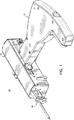
一般に、図1に示されているように、生検装置10として後述されている生検システムは、キャリッジ格納庫12、挿入ユニット14などのような生検機器、および、発射モジュール16を有している。装置の上述の各要素が協働して複数の組織標本の回収を容易にするが、この場合、挿入ユニット14は、刺し通し先端78などのような先端部と、患者の胸部の目標となる塊状部に導入される組織バスケット80などのような側腔とを有している真空チューブ76を備えている。組織バスケット80に隣接している領域に伝達される吸引力が組織支持プレート82などのような真空プレートに付与されて、目標となる組織塊状部の少なくとも一部を組織バスケット80に引き入れる。周囲の組織塊状部から狙った組織部分を切断するために、ナイフチューブ64を、回転させながら、真空チューブ76の外面の周囲を遠位方向に前進させる。
【0030】
目標の組織部分を切断してしまうと、標本を撤回するために、ナイフチューブ64を通して真空チューブ76を刺し通し先端78と一緒に後退させる。特に、後退時には、組織バスケット80は組織収容器の位置に隣接して露出状態となる。組織収容器位置まで真空チューブ76を後退させると、狙った組織部分と接触している組織支持プレート82へと組織剥ぎ取りプレート110が持ち込まれ、狙った組織部分を支持プレートから取り除くが、同組織部分を収容器の中へ落ち込ませるようにするのが好ましい。代替例として、剥ぎ取りプレート110を省いて、鉗子を用いて掴むといったような従来式の方法で、組織を回収してもよい。目標の組織部分の回収などの詳細な説明は、デイビッド・ファラキオーニ(David Faracioni)らにより1998年2月20日に出願された米国特許出願連続番号第09/040,244号に提示されており、この特許出願の全内容は引例として本文中に援用されている。
【0031】
幾つかの図の全体で同一参照番号が類似要素または同一要素を同定している添付の図面を特に詳細に参照し、まず、図1を参照すると、1つの好ましい実施形態が生検装置10として全体が示されている。上述のように、生検装置10はキャリッジ格納庫12、挿入ユニット14、発射モジュール16を備えている。図4を一寸参照すると、挿入ユニット14はキャリッジ格納庫12内に回収され、格納庫と作動可能に嵌合するように、その内部で支持されている。発射モジュール16は、キャリッジ格納庫12および挿入ユニット14と作動可能に嵌合するように、キャリッジ格納庫12に形成された開口内部に横方向に受容されている。
【0032】
図2に示されているように、キャリッジ格納庫12は近位端20から遠位端22まで軸線方向に延びて、その内部に、挿入ユニット14を支持するとともに発射モジュールを受容する(図1)ことを目的とした空洞24を規定している。キャリッジ格納庫12は駆動ユニットと、挿入ユニット14のシステム制御系素子とを備えているのが好ましい。駆動ユニットおよびシステム制御系の具体例は、1998年2月20日に出願された「生検機具駆動装置(Biopsy Instrument Drive Apparatus)」という発明名称の米国特許予備出願連続番号第60/078,748号に開示されており、その全内容は引例として本文中に援用されている。
【0033】
図2から図4を参照すると、キャリッジ格納庫12はカバー26を備えており、これは格納庫12内部に挿入ユニット14を維持するようにキャリッジ格納庫12に蝶番式に装着されている。カバー26にはタブ28が搭載されており、図3Aに示されているように、カバー26に搭載されたH字型ラッチ30を受容および維持している。H字型ラッチ30はフット32を備えており、これは、図3に示されているようにキャリッジ格納庫12の内部に備えられてカバー26を閉鎖位置に維持するためのカバーラッチ組立体34と協働するためのものである。
【0034】
カバーラッチ組立体34は外側ラッチ36および内側ラッチ38を備えている。外側ラッチ36および内側ラッチ38はH字型ラッチ30のフット32と協働して、カバー26を閉鎖位置に維持している。格納庫12は、挿入ユニット14の組織バスケットの配向のためのホイールノブ40を更に備えている。ホイールノブ40は、アナログクロック構造を利用して挿入ユニット14の真空チューブ76(図7)を回転させて調節される。多様な増分構造を利用して、挿入ユニット14の位置決めを操作することができるものと解釈される。
【0035】
ホイールノブ40はカバーラッチ組立体34と協働して、カバー26が開放位置にある間に、「12時」の位置にホイールノブ40を維持する。図1および図3に示されているように、内部ラッチ38はピン230を備え、カバー26が開放位置にある間は、「12時」の位置にホイールノブ40を係合させることができる。開放位置では、ホイールノブ40を装着させるシャフト56がラッチ組立体34と係合する。
【0036】
図3Bに例示されているように、キャリッジ格納庫12はノブロック50を備えている。ノブロック50は上方向に弾性偏倚される。ノブロック50はカム51により下方向に向けることができ、カムはカバー26に搭載されているのが好ましい。カバー26を操作して開放位置まで移動させると、ノブロック50はカム51により上方向に向けられる。ノブロック50は、背面ホイールノブ54の受容とロックのためのチャネル53を規定している。背面ホイールノブ54は平坦部55を有し、チャネル53に係合している。ホイールノブ40および背面ホイールノブ54は、概ね平行な配向でキャリッジ格納庫12に位置決めされ、かつ、図3に示されるように、シャフト56により装着される。
【0037】
キャリッジ格納庫12は、図3および図3Bに示されているナイフチューブ制御系42を更に備え、挿入ユニット14のいずれかの側(図8に示されているとともに、後述される)からナイフチューブ64の運動を制御している。ナイフチューブ制御系42は1対の手動ノブ46を備えており、ノブが一個ずつ、挿入ユニット14の各側に配置されて、ナイフチューブ64の前進および後退を制御している。手動ノブ46は、選択された範囲の両極限の間で偏倚する或る一定範囲の運動にわたって回転自在である。マニュアルノブ46は、約60度のストロークを含む或る一定範囲の運動を行うのが好ましい。ナイフ前進組立体42は、レバーアームの上にボールベアリング組立体と一緒にカムフェイスを備えており、荷重が徐々に増大してオーバーセンター位置で最大閾に達して、ナイフチューブ64をより厳密かつ容易に制御するための人間工学的特性を向上させるのが最も好ましい。
【0038】
キャリッジ格納庫12は、図3および図4に示されたキャリッジ組立体400を備え、挿入ユニット14の受容に備えてもいる。キャリッジ組立体400は、ナイフチューブ64を受容および支持係合するためのナイフキャリッジ410と、挿入ユニット14の真空チューブ76(図3に示されているとともに、後述される)を受容および支持係合するための套管針キャリッジ420とを備えている。
【0039】
図5から図8に示されているように、挿入ユニット14はキャリッジ格納庫12の内部に支持されている。挿入ユニット14は、図8の展開図に最良に示されているように、解放ストリップ60のような較正器部材を備えており、これは、キャリッジ格納庫12内部における支持の適正な軸線方向回転位置に挿入ユニット14の各部材を維持する。解放ストリップ60は、挿入ユニット14をキャリッジ格納庫12の内部に1配向のみに位置決めすることができるように構成されており、この結果、挿入ユニット14は、用途ごとにホイールノブ40の整列と関連して適性に較正される、すなわち、「整合」される。
【0040】
挿入ユニット14は1回きり使用の使い捨て可能な荷重ユニットであるのが好ましく、すなわち、1回だけ挿入しただけで複数の生検標本を獲得した後は廃棄することができることを意味する。挿入ユニット14は、再利用可能なキャリッジ格納庫12に装着するのに適している。図5に示されているように、挿入ユニット14は、患者に経皮導入するように構成され、そのように寸法設定された挿入端部62を備えている。挿入端部62はキャリッジ格納庫12の遠位端22から延在している。
【0041】
図8を参照すると、挿入ユニット14は一連の同心配置された管状部材を備えている。かかる管状部材の第1のものはナイフチューブ64であり、これは、傾斜角を付した切断表面66がその遠位端に形成されているとともに、横方向に面した組織排出ポート68が環状の切断表面66よりも近位方向に配置されている。流体の除去などを補佐するために、横方向に配向された真空ポート70が挿入ユニット格納庫72の遠位端に隣接しているのが分かるが、ユーザが作動させることができる真空源(図示せず)に接続されているのが好ましい。
【0042】
ギア74はナイフチューブ64に堅固に搭載されている。組立て式ナイフチューブ64はキャリッジ格納庫12の内部で支持される。ギア74は市場で入手可能なモータに接続されたギアと係合して、約1200rpmでナイフチューブ64を回転させる。ナイフチューブ64はキャリッジ格納庫12の内部に配置され、格納庫が回転運動と長手方向並進運動とを同時に行うことを容易にしている。
【0043】
真空チューブ76はナイフチューブ64の内部に同心配置されて、刺し通し先端78が環状の切断表面66を越えてナイフチューブ64の遠位端から外へ延びるようにしている。この態様で、刺し通し先端78およびナイフチューブ64は、圧迫された胸部などの患者の組織に挿入するための、実質的に切れ目の無い刺し通し組立体を形成している。組織バスケット80は真空チューブ76の遠位端に隣接して形成されている。組織バスケット80は横方向に面しており、組織支持プレート82によって輪郭が規定されており、この支持プレートには、それに沿って長手方向に形成された一連の真空穴84が設けられている。最近位の真空穴86がこの一連の穴84から或る一定距離に形成されている。ナイフチューブ64の遠位端を封止する補佐を行うために真空穴86が設けられて、装置10を通る真空力の過剰な損失を防いでおり、残余の真空穴84が組織バスケット80に狙った組織を効果的に引き入れることができるようにしている。
【0044】
図6および図7の断面図に示されているように、組織プレート82は弧状に構成され、溶接などにより真空チューブ76に固着され、真空チューブ76の遠位端の付近に実質的に切れ目の無い表面陥凹部を形成しているのが好ましい。組織プレート80の弧状または正弦波状の形状は、ナイフチューブ64が挿入点における装置10の最外径を表しているという事実と組み合わせると、他の既存の組織採取装置の幾何学的形状を利用した場合よりも、より大型の組織標本を採取するのを容易にする。
【0045】
再度、図8を参照すると、真空ポートアダプタ90がナイフチューブ64の近位端92に堅固に取り付けられている。ギア74がナイフチューブ64の周囲で真空ポートアダプタ90に協働状態で嵌合している。真空ポートアダプタ90は真空ライン96に堅固に取付けられている。真空ポート98は開口100を規定し、真空ライン96の近位端102に堅固に取り付けられている。真空ポート98は流体密封係合状態で真空カラー104の内部に載置されている。真空カラー104は真空コネクタ106を受容する。真空コネクタ106は真空ホース(図示せず)の装着を容易にするが、このホースは真空源(図示せず)に接続されて、真空ライン96に真空を供給する。真空ライン96は真空チューブ76と流体導通状態にあり、真空チューブ76は組織バスケット80と流体導通状態にある。
【0046】
組織バスケット80の内部からの組織標本の抽出は修正型のリーフばねの様式である組織剥ぎ取りクリップ110によって容易にされるが、このクリップは、組織排出ポート68と整列した状態で、ナイフチューブ64の上に滑動自在に搭載されるように構成され、そのような寸法に設定されたカラー部112を備えている。カラー部112は側面が開放状態になっていてもよい。組織剥ぎ取りクリップ110は内方向に偏向した遠位端部114を備えており、この端部は、真空チューブ76の外側表面に抗して圧偏倚するように保持されて、ナイフチューブ64の内部で真空チューブ76が後退した時に、組織標本の剥ぎ取りを容易にする。組織剥ぎ取りクリップ110には被覆材または潤滑材が更に設けられて、抽出された標本組織と接触状態になり得る組織剥ぎ取りクリップ110の表面に沿った摩擦力を低減するようにしてもよい。この態様で、組織は、組織剥ぎ取りクリップ110に付着する可能性を減じた状態で、組織バスケット80から一層容易に撤回される。いかなる好適な公知の摩擦低減被膜を組織剥ぎ取りクリップ110および/または組織プレート82に付与してもよい。
【0047】
放射線透過性の外側チューブ120は滑動クリップ124に装着されるが、このクリップは格納庫72にその遠位端で取外し自在に装着される。外側チューブ120は放射線透過性であるため、放射線不透過性のナイフチューブ64および真空チューブ76が存在していなくても、罹病の疑いがある組織の画像化にあたり、組織採取現場に残存させてもかまわない。組織標本領域の表示をユーザに提供するために、外側チューブ120には周辺線のような少なくとも1つの放射線不透過性のマーキングが設けられて、標本回収現場の長手方向間隔を示すようにするのが好ましい。
【0048】
滑動クリップ124には1対の削除可能な脚部126が設けられており、これら脚部は、格納庫72の下側に形成された並列受容式スロットの内部に嵌合する。受容式スロット128は格納庫72の下側に形成されている。1対の菱形のカム表面130が格納庫72の下側の壁部分に沿って形成されている。カム表面130は、滑動クリップ124の長手方向運動に抵抗する一時的抑止具として作用する。滑動クリップ124が完全に遠位方向に移動した時には、狙った組織塊状部の挿入部分で外側チューブ120の遠位端が組織バスケット80の位置のうちでもその遠位端部と実質的に整列状態になって、罹病の疑いがある組織領域から装置10を撤回した際に、組織の標本回収現場の部位にマーカーを供与する。
【0049】
ここで暫時、図5を参照し直すと、挿入ユニット14が格納庫12の内部に挿入ユニット14を適切に設置するための指標化装置矢印150を備えている。
【0050】
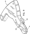
ここで図9から図16を参照しながら、発射モジュール16を詳細に説明する。図9および図10に例示されているように、発射モジュール16は装置10との係合前の状態が示されている。図4に示されているように、発射モジュール16の挿入端15がキャリッジ格納庫12の内部で横方向に、かつ、滑動自在に挿入されている。
【0051】
発射モジュール16は、図11、図11A、および、図11Bに示されているように、発射モジュール16をキャリッジ格納庫12に解放自在に固着するモジュールラッチ組立体180を備えている。モジュールラッチ組立体180のラッチインターフェイス181はピン182を中心として旋回し、ラッチばね183により反時計方向に弾性偏倚させられて、キャリッジ格納庫12に嵌合する。発射モジュール16をキャリッジ格納庫12から解放するために、モジュールラッチ組立体180は、キャリッジ格納庫12から発射モジュール16を解放するように手動で押し下げるラッチ解放ボタン184を備えている。
【0052】
図11、図11B、図13、および、図14に示されているように、発射モジュール16は解放組立体300のような発射安全機構を備えており、この機構は、発射モジュール16が装置10から係合解除された時のラム190の射撃を防止している。発射解放組立体300はカム302、ピン304、ばね306、ラッチピン308を備えている。カム302とばね306とはピン304により支持され、また、ラッチピン308により固定されており、この時、ピン304は発射モジュール16(図9)から外に延在している。発射解放組立体300は、ばね306により軸線方向に弾性偏倚されている。発射モジュール16はキャリッジ格納庫12に挿入されており、ピン304は付勢カム302を後方に押し下げて、図13および図14に示されているように、ラム190の運動を可能にしている。
【0053】
図11Bに示されているように、発射モジュール16は、ラムピン192によってロッカーアーム194に固着的に取付けられているラム190を備えている。ロッカーアーム194は発射モジュール16に取付けられており、ベアリング組立体196を中心として旋回し、ラム190の運動を容易にする。ベアリング組立体196はベアリングフランジ310、スラストワッシャ312、および、ベアリングピン314を備えている。
【0054】
発射モジュール16は、ロッカーアーム194を作動させるための発射ばね202を更に備えている。ロッカーアーム194はロッカーロッド195を有して、その上に発射ばね202を支持している。発射ばね202は、発射モジュール16に固着的に取付けられたばねロッド204上に更に支持されている。ばねロッド204およびロッカーロッド195は、発射ばね202をロッカーアーム194と能動的係合状態にするための誘導支持を供与している。撃発準備ラッチ解放組立体206はロッカーアーム194と嵌合して、ばね202をばねロッド204上の圧縮位置に維持している。この構成はばね202内に最大潜在エネルギーを供与し、これが、解放状態になった時に、ばね202の最大運動エネルギーをロッカーアーム194に伝達する。
【0055】
撃発準備ラッチ解放組立体206は、ピン324の周囲の撃発準備ばね322によって弾性偏倚された撃発準備ラッチ320を備えている。撃発準備ラッチ320はピン324を中心として揺動し、ロッカーアーム194を解放してラム190を発射させる。ロッカーアーム194との係合から撃発準備ラッチ320を解放するためには、トリガーボタン208を押し下げる。トリガーボタン208はピン211によって発射モジュール16に取り付けられ、撃発準備ばね322によって撃発準備ラッチ320に抗して弾性偏倚させられる。撃発準備ばね322はラッチ脚部321によってラッチ320上に支持される。発射モジュール16は、撃発準備アーム210を利用してばね202をロックアーム194と係合接触状態で最大潜在エネルギー位置まで圧縮させて、リセットし、すなわち、再度撃発準備させることができる。
【0056】
撃発準備アーム210は発射モジュール16に搭載されており、撃発準備アームピン212を中心として旋回する。撃発準備アーム210は、図15および図16に最良に示されているように、アームばね216によって、ピン212を中心として反時計方向に弾性偏倚される。撃発準備アーム210は、ベアリングピン201によって支持されている撃発準備ベアリング200を更に備えている。図15に示されているように、非撃発準備位置にあって、ベアリング200はロッカーアーム194に接触する。撃発準備アーム210は時計方向に操作され(図16の斜視図に見られるように)、それにより、ベアリング200がロッカーアーム194を付勢して撃発準備ラッチ解放組立体と係合状態にさせ、また、リセットされた配向にさせる。ロッカーアーム194の撃発準備はラッチ320を利用したカム運動を強制し、これにより、ラッチはトリガーボタン208をリセットし、発射モジュール16に発射させて、ラム190に挿入ユニット14を駆動させる。発射モジュール16は、キャリッジ格納庫12のいずれの側で滑動自在に受容されてもよい。
【0057】
ここで図13から図16を参照しながら、生検装置10の動作をここで説明する。装置10は診断生検用の多様な誘導システムと互換性があり、修正を最小限にして、或いは、全く修正せずに、かかる誘導システムとの交換能力を提供している。この多目的性は、一部には、その新規な構成のゆえであるとともに、システムとは別個の要素である取外し自在な発射モジュール16のために格納庫12の全長が低減されているせいである。
【0058】
図4に示されているように、カバー26は開放位置まで操作される。図3に示されているように、外側ラッチ36は反時計方向最深位置にあり、内側ラッチ38は時計方向最深位置にあって、H字型ラッチ30のフット32の受容に備えている。ホイールノブ40は「12時」の位置にあって、キャリッジ格納庫12内に挿入ユニット14のナイフチューブ64および真空チューブ76をそれぞれに受容し、かつ、それらの支持係合するためのナイフキャリッジ410および套管針キャリッジ420を適切に配向し、かつ、位置決めしている。内側ラッチ33上のピン230はホイールノブ40を「12時」の位置に維持し、また、ピンは内側ラッチ38に固着的に取付けられている。
【0059】
図3Bおよび図3Cに示されているように、背面ホイールノブ54およびノブロック50は、挿入ユニット14を受容し、かつ、それに支持係合するためのナイフキャリッジ410および套管針キャリッジ420を位置決めした状態に維持するようにも機能する。ホイールノブ50および背面ホイールノブ54はシャフト56を介して協働する。
【0060】
挿入ユニット14はキャリッジ格納庫12の内部に据付けられる。キャリッジストリップ60は挿入ユニット14から撤回され、各構成要素がキャリッジ格納庫12にスナップ式に嵌入する。カバー26は閉鎖状態になる。ホイールノブ40および背面ホイールノブ54を後方に滑動させて、ラッチ組立体34とノブロック50から、それぞれに係合離脱させることができる。ラッチ組立体34はフット32と係合して、カバー26を閉鎖位置に維持するとともに、キャリッジ格納庫12による挿入ユニット14の支持を維持する。
【0061】
装置10はここで、定位誘導システム(図示せず)のような画像化誘導システム上に据付けられる。発射モジュール16はキャリッジ格納庫12の内部に滑動自在に挿入される。クロックホイールノブ40は約0.94インチの距離だけ逆に滑動されて、患者の病巣を刺し通すための套管針キャリッジ420に嵌合接触させるように突出させられるラム190に接触させるのが好ましい。撃発準備アーム210を操作して、発射モジュール16のラム190を発射準備位置へと起こす。
【0062】
発射開放組立体300を押し下げて、ラム190の運動を可能にする。ホイールノブ40および背面ホイールノブ54をラム190と接触関係になるまで後方に滑動させる。
【0063】
定位誘導システムを調節して、挿入ユニット14の先端部62を診断治療のために罹病の恐れがある病巣(図示せず)に隣接させる。トリガーボタン208を押し下げて、ラム190にその運動エネルギーを套管針キャリッジ420に付与させて挿入ユニット14と嵌合させ、それにより、病巣を刺し通す。ラム190は套管針キャリッジ420を前方に駆動するにすぎず、それにより、ラム190により作用される総質量を最小限に抑えるとともに、真空チューブ76に付与される力を最大限にするのが好ましい。
【0064】
図17および図18を参照すると、挿入して、胸部生検標本すなわちサンプルなどのような組織を回収するための、生検システム510として概略が例示された、生検システムの代替例が開示されている。生検システム510は、格納庫512と、挿入ユニット514のような生検機具とを備えている。挿入ユニット514は格納庫512と動作的に関連しており、機具全体を1回だけ経皮的に挿入するだけで、患者から複数の組織標本を撤回するような構成にされ、かつ、そのような寸法に設定されている。
【0065】
発射モジュール516は格納庫512と取外し自在に嵌合し、挿入ユニット514と動作的に関連して、患者の目標部位に向けて生検機具の少なくとも一部分を選択的かつ迅速に前進させるのを容易にしている。発射モジュール516は、挿入ユニット514との動作上の関与を目的として、格納庫512によって輪郭規定される空洞518の内部に横方向に受容される。開示された生検システムの利点の1つとして、患者からシステム全体を引き出さずに、罹病の疑いがある組織の複数の標本をオペレータが抽出するのを容易にすることが挙げられる。更に、このシステムは、生検機具と相対的な多様な半径方向の向きからの標本採取を効果的に可能にしている。この結果として、瘢痕は最小限となり、また、患者が通常の活動を直ちに再開することを許容する通院治療状態をもたらす。生検システム510は検針テーブル装備、直立テーブル装備、または、診断/治療装置構造体と協働していてもよい。
【0066】
格納庫512はシステム510の近位端から遠位端まで軸線方向に延在しており、また、挿入ユニット514を支持するための空洞520を規定している。格納庫512はモータ取付式駆動ユニットとシステム制御装置とを備えている。駆動ユニットおよびシステム制御装置の一例が、前述の米国予備出願連続番号第60/078,748号に開示されている。
【0067】
図19を参照すると、生検システム510は格納庫512内に幾つかの作動用の構成要素および機構を備えている。格納庫512は、多様な構成要素を封入するための側面カバー522、正面カバー524、背面カバー526、および、基部プレート528を有している。
【0068】
キャリッジ530は格納庫512の内部に滑動自在に配置されており、格納庫512の内部に挿入ユニット514の少なくとも一部を離脱自在に維持するように構成されている。キャリッジ530は、オーバーセンター配置が発射モジュール516の作動後に適正位置に挿入ユニット514を維持するように構成された維持機構である。維持装置532は駆動スレッド534に取付けられて、套管536を中心として回転運動する。ばね537は套管536の周囲における維持装置532の弾性運動を容易にする。
【0069】
図19および図20を参照すると、駆動スレッド534はキャリッジレール670により格納庫512内で支持されている。キャリッジレール670は背面カバー526に装着され、套管536によって受容される。ロックアウト672はキャリッジ530の底部表面に装着される。ロックアウト672は遠位移動止め674と近位移動止め676と協働して、キャリッジ530の運動限界を設けている。組織バスケット牽引スライド678をキャリッジ530に取付けて、キャリッジの操作に備えている。組織バスケット牽引スライド678は、バー682によって装着されたレバー680を有している。止め684は最遠位位置におけるキャリッジ530の運動を阻止している。止め684は、挿入ユニット514の各部を受容するための空洞686の輪郭を規定している。
【0070】
挿入ユニット514は、格納庫512の内部に離脱自在に受容するための駆動スレッド534の空洞538の内部に離脱自在に受容されている。空洞538の内部に受容した際に、維持装置532は挿入ユニット514を適所に維持させられる。発射モジュール516の作動時には、維持装置532が撃発準備のためにモジュール内の挿入ユニット514の運動を可能にすると同時に、その適切な位置設定を維持している。
【0071】
光学センサー540が生検機具514(より詳細に後述する管状ナイフ部材などのような)の一部に隣接して配置されている。光学センサー540は挿入ユニット514上に配置されたマーカー(図示せず)を検出するような配向にされて、図39に関して詳細に後述される挿入ユニット(管状ナイフ部材の横方向開口部のような)の向きを判定する。光学センサー540は、一般に参照番号542と指定されたプログラミング可能論理制御回路などのような、位置を検知するとともに配向を判定するための、当業者に公知の所要のエレクトロニクスおよびハードウエアを備えている。かかる回路の細部を、図35を参照しながら本文中に詳細に後述する。
【0072】
図20を参照すると、挿入ユニット514が格納庫512の内部で支持されている。挿入ユニット514は、図21に示されているように、格納庫512を装填するのに適切かつ相対的な軸線方向および半径方向の配向に挿入ユニット514の各構成要素を維持するための、較正装置544などのような解放ストリップを備えている。較正装置544は挿入ユニット514と一緒に形成された開口部545に受容される。
【0073】
図22を参照すると、較正装置544は挿入ユニット514に嵌合するためのぺグ547を備えている。図23および図24を参照すると、ぺグ547は挿入ユニット514の各部(後述するナイフチューブおよび真空チューブのような)と嵌合して、挿入ユニット514の組織バスケットが「12時」の位置に位置決めされるといったような適切な配向に挿入ユニット514が格納庫512内に位置決めされて、システム510の整列と関連して挿入ユニット514が適切に較正されるようにすることができる。これは、挿入ユニット514の各構成要素が、後述するように、格納庫512へとスナップ式に嵌入することが可能であるといったような協働を容易にする。較正装置544は、後述する組織バスケットが「12時」の位置に来るような向きにも、挿入ユニット514を配向する。組織バスケットが「12時」の位置に無い限り、挿入ユニット514は格納庫512の内部に装填され得ない。これは各構成要素の不整合と、組織バスケットの不正確な位置決めとを効果的に防止している。挿入ユニット514は1回きりの使用の装填ユニットであり、異なる各種格納庫と交換可能であるものと解釈される。
【0074】
図21を参照すると、挿入ユニット514は一連の同心配置された管状部材を備えており、同部材は、図1から図17に関して説明したものと同様に、ナイフチューブ548などのような管状ナイフ部材を備えている。ナイフチューブ548は傾斜を付けた角切断面550と、横方向に面した組織排出ポート52などのような、前述の切断面を貫通して形成された横方向開口とを有している。ナイフチューブ548の作動と真空源への接続は、前述のとおりである。
【0075】
挿入ユニット514は、図1から図17に関して説明した真空チューブ76と同様に、ナイフチューブ548の内部に同軸配置された、套管針554などのような第1の管状部材も備えている。組織バスケット556は套管針554の遠位端に隣接して形成されているとともに、図1から図17に関して記載したものに類似した構成にされ、そのような寸法に設定されている。真空ライン555は套管針554の管腔と流体連絡状態に設置されている。標本を回収するための動作と真空源への接続も、同様に、後述する。
【0076】
放射線透過性の外側チューブ710を滑動クリップ712に装着させるが、このクリップがその遠位端において挿入ユニット514への着脱自在な装着を可能にする。外側チューブ710は放射線透過性であって、放射線不透過性のナイフチューブ548および套管針554が存在していない場合には、罹病の疑いがある組織の画像化のための組織標本採取現場に残留させることができる。組織標本採取領域の指標をユーザに与えるために、外側チューブ710には周辺線のような少なくとも1種の放射線不透過性のマーキングを設けて、標本採取現場の長手方向の間隔を示すようにするのが好ましい。
【0077】
滑動クリップ712には1対の偏向自在な脚部714が設けられ、これらが挿入ユニット714の下側に形成された平行な受容スロット716の内部に嵌合する。1対のカム表面718が挿入ユニット514の下側の壁部分に沿って形成されている。カム表面718は暫定止めとして作用し、これらが滑動クリップ712の長手方向運動を阻止している。滑動クリップ712は空洞720を備えており、この空洞の中に在る外側チューブ710を整列させ、同チューブを支持している。挿入ユニット514の空洞722も外側管710と整列し、それを支持する。
【0078】
滑動クリップ712が完全に遠位方向に移動した時には、狙った組織の塊状部への挿入地点で外側チューブ710の遠位端が組織バスケットの位置のうち遠位端部分と実質的に整列状態になり、従って、罹病の疑いがある組織領域から装置510を撤回した時に、組織の標本採取現場の位置に対してマーカーを付与する。
【0079】
生検システム510は、組織バスケット556を選択的に配向させるために、挿入ユニット514と作動的に嵌合可能な指標化組立体558を備えている。指標化組立体558は、套管針554と、指標化組立体558の指標化運動を容易にする指標化ギア組立体688と協働状態で配置されたカム組立体を備えている。カム組立体は、先の標本が採取された位置を効果的に想起させ得る異なる半径方向の配向で組織バスケット556を保有しながら、装置510に標本採取させることができる。この構成により、先の標本の位置を呼び起こすとともに、後続の標本撤回処理について適切な位置を得るための再設定を行う自動指標化機能が付与されるが、これは標本処置手順の効率を有利に向上させる。
【0080】
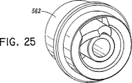
図21に示されているように、図25から図28と関連して、指標化組立体558は、図25および図26に示された、套管針554に取付けるための第1のカム部材562を備えている。第1のカム部材562は、図27に示されているように、格納庫512の内部に配置されている第2のカム部材564と協働するように構成されて、別個の組織標本を獲得するために所定の配向に組織バスケット556を向ける。第1のカム部材562は、図28に示されているように、格納庫512の内部に配置された第3のカム部材566と協働するように構成されて、組織標本を撤回するために所定の配向に組織バスケット556を向ける。
【0081】
図29を参照すると、指標化組立体558は、図20に示されているように、組織バスケット556を選択的に配向するように構成された手動伝動組立体563を備えている。手動伝動組立体568は1対のサムホイール571を備え、組織バスケット556の手動配向と格納庫512の内部の適切な整列とを容易にする。第2のカム部材564は、システム510の標本回収、標本撤回、または、組立てを目的とした所望の半径方向の配向に対して組織バスケット556を指標化するために、手動ギア組立体568を利用して配向される。図19を一寸参照すると、サムホイール571が指標キャリッジ690によって格納庫512の内部に支持されている。側面カバー522は開口692を規定し、サムホイール571の少なくとも1部をその操作のために露出させている。
【0082】
図29を引き続き参照すると、システム510が手動ギア組立体568のサムホイール571を操作することにより組立てられて、第2のカム部材564が「12時」の位置に来るようにしている。ナイフチューブ548は第2のカム部材564によって受容されている。これに対応して、図30に示されているように、第1のカム部材562がキャリッジ530により受容され、これによって、維持装置532がその中に第1のカム部材562と挿入ユニット514とを維持している。
【0083】
図31を参照すると、第2のカム部材564がその中の套管針554を利用して「12時」の位置に配向された状態で、別個の組織標本からの組織の撤回はシステム510によって容易にされている。第1のカム部材562が套管針554に取り付けられている。図32を参照すると、套管針554および第1のカム部材562が、矢印Aと示されているが、前方に駆動され、第1のカム部材562は容量を指標化するための第2のカム部材564と協働するようになる。第1のカム部材562が第2のカム部材564と協働すると、第1のカム部材562は、組織バスケット556を適切に整列させるために矢印Bで示されているように回転させられて、別個の組織標本の回収に備える。
【0084】
手動ギア組立体568のサムホイール571(図29)を操作して、組織標本採取現場に隣接した組織バスケット556を配向させる。指標止め569(図19)は指標化組立体558の伝動動作と協働して、組織標本の回収するために套管針554についての、また、同套管針と相対的な「2時間」ごとの増大を容易にしている。システム510を利用して套管針554を後退させて組織標本を撤回した際に、第2のカム部材564の配向には影響が及ばず、先の標本をどこで回収したかについての位置の記憶を効果的に供与している。
【0085】
図33から図35を参照すると、組織標本の撤回は、第3のカム部材566を採用しているシステム510によって容易にされる。套管針554および第1のカム部材562は、矢印Cによって示された近位方向に駆動されて、第1のカム部材562は第3のカム部材566と協働する。第1のカム部材562が第3のカム部材566と協働すると、第1のカム部材562は図Dに示されているように回転させられ、組織バスケット556をあちこちの側へと配向する。オペレータは常に真空エルボー573の配向を正して、現在指向されている側から逸れる方向を指向するようにするので、図33に示されているように、第1のカム部材566が真空源(図8に関して後述する)への接続部と正反対に組織バスケット556を配向させるのが有利である。
【0086】
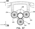
図36から図38を参照すると、生検システム510は、格納庫512の内部に配置され、かつ、ナイフチューブ548の線形作動を実施するように構成された線形前進制御組立体570を備えている。組立体570は、格納庫512と一緒に取付けられ、かつ、ナイフチューブ548の線形運動を実施するように構成されたベアリング574を備えている。3つのベアリング574は、ナイフチューブ548の回転時にその軸線方向並進運動を実施する部分的に螺旋状のネジ構成をベアリング574の接触表面575が形成しているのが好ましい。特に、図38に示されているように、ベアリング574の各々は長手方向軸線から角度αだけオフセットした状態で傾斜されている。1つの特定の効果的な角度は約2度である。
【0087】
典型例として、これらのベアリングは120度の間隔が設けられている。しかし、本件開示の生検システムのために、ベアリングの間隔は有利に修正されている。図37を参照すると、ベアリング574は互いに相対的に配向されて、管状ナイフ部材548がベアリング574のうちの2個の間でスナップ式に嵌入状態になり得るようにしている。ベアリング574はナイフチューブ548の周囲に同心配置され、それと接触状態になる。
【0088】
ナイフチューブ548の回転は電気モータ576(図19)によって実施されるのが好ましい。駆動ギア列694はモータ576と動作的に関連しており、ナイフチューブ548の回転を実施する。ベアリング574はナイフチューブ548の回転を軸線方向並進運動に変換する。生検システム510の自動送り特性は、電気モータ576にナイフの送り速度またはナイフの前進を設定させることができる点で有利である。
【0089】
弾性組織に遭遇した場合には、ベアリング574によって形成された螺旋状ねじがナイフチューブ548を滑動させて、ナイフチューブ548が組織を寸断するまで回転を継続しながら、その前進を減速してゆく。ナイフチューブ548を前進させると、組立体570が送り速度を減速させ、ナイフチューブ548が所望の組織標本を完全に切断する。組立体570は、上述のスナップ式嵌入特性によって更に向上したナイフチューブを前進させるための複雑な機構の必要性を取り除いている。
【0090】
図19を一寸参照すると、ナイフチューブ牽引機構696が駆動ギア列694と嵌合して、ベアリング574の間の組織標本部位からナイフチューブ548を後退させる。ナイフチューブ牽引機構96はそれを操作するためのレバー698を備えている。カム700が、ギア列694に嵌合するための機構696に取付けられている。ねじれネジ702がその可動限界間で機構696を偏倚させる。
【0091】
上述の胸部生検処置手順などのような手術中には、挿入ユニット514が生検システム510の残余の構成要素と共に組立てられる。較正装置544は予備パッケージングされて、挿入ユニット514と一緒に組立てられ、図20から図24に関して先に論じたように、挿入ユニット514の各構成要素の適切な配向を維持する。挿入ユニット514を格納庫512と動作可能に接続した場合には、較正装置544が除去される。
【0092】
挿入ユニット514がシステム510と嵌合し、それにより、挿入ユニットの各部が適所に受容され、或いは、スナップ式に嵌入する。上述のように、ナイフチューブ548は第2のカム部材564(図29)により受容される。第1のカム部材562は、套管針554に取付けられるが、キャリッジ530(図30)により受容され、ナイフチューブ548はベアリング574間にスナップ式に嵌入させられる。生検機具514はシステム510により解放自在に維持されるのが有利である。
【0093】
生検システム510は、上述のものに類似する定位誘導システムなどのような画像化誘導システムに据付けられる。発射モジュール516は、生検機具514と動作的に関連するように、格納庫512の空洞518と離脱自在に係合している。発射モジュール516を操作して発射モジュール516に撃発準備させ、図1から図17に関して論じたものと類似する生検システム510を発射させることができる。簡単に言うと、発射モジュール516の発射時に、ハンマー517(図31)をキャリッジ530に対して押し付けることにより、套管針554を選択した目標組織領域へと迅速に押し込む。代替例として、生検システム510における据付け前に、発射モジュールを予備的に撃発準備状態にすることができる。
【0094】
指標化組立体558は、図29から図35に関して記載したものと同様に、組織バスケット556を選択的に配向するように挿入ユニット514と係合する。套管針554に取付けられた第1のカム部材562は第2のカム部材564と協働するように遠位方向に駆動されて、組織バスケットの配向を有効に指標化する。手動の伝動組立体568を操作して、罹病が疑われる病巣または所望の組織標本の所在である(図示せず)場所に所望の配向で組織バスケット556を位置決めする。
【0095】
ナイフチューブ548を作動させることにより、プログラミング可能論理制御装置(本文中に更に詳細に後述する)が電気モータ576(図19)を始動させ、これがナイフチューブ548の回転を引き起こす。線形前進制御組立体570はナイフチューブ548の動作を制御するが、その一例として、図36から図38に関して論じたように、別個の組織標本を切断するための送り速度の制御が挙げられる。先に注目したように、弾性組織に遭遇した場合に、ナイフチューブ548は軸線方向に滑動させられて、所望の組織を除去するまで送り速度を低減してゆく。第1のカム部材562を近位方向に駆動して、図33から図35に関して論じたように、組織標本を撤回するために第3のカム566と協働させる。第1のカム部材562を遠位方向に駆動して第2のカム部材564と協働させて、先の標本位置についての組織バスケット556の配向を想起させるのが有利である。先の組織をどの位置から標本採取したかを知ったうえで、後続の別個の標本を同一位置または別途選択した位置で回収することができる。
【0096】
図39を参照すると、生検システム510はプログラミング可能論理制御システムを備えている。手術中は、挿入ユニット514を位置決めして発射準備が完了してしまうと、前述の例と同様に、ユーザーが発射モジュール516の発射ボタンを押す。発射モジュール516のハンマーが套管針キャリッジ530に衝撃を加えて、それを迅速に遠位方向に移動させることにより、組織バスケット556と一緒に套管針54を狙った組織領域に陥入させる。切断過程を開始するために、ユーザーは可能化スイッチ621aまたは621bの一方(所与の手順のために生検システム510がどのように装備されているかに依存して、格納庫512の右側か左側のいずれかの側に配置されている)を押す。この動作によってインターフェイス回路620aまたは620bを介して信号を送信するが、同回路が今度は処理信号をプログラミング可能論理制御装置(PLC)610に送信する。それにより、論理状態を変更して可能化されたモードにし、このモードが可能化信号をモーター駆動装置630に供与し、従って、モーター駆動装置630がモーター576を制御できるようにする。可能化スイッチはオン−オフ型の交互動作のスイッチであり、すなわち、1回押してオン状態にし、再度押してオフ状態にし、これに対応して可能化されたLED(発光ダイオード)インジケータをオン状態にする。
【0097】
ナイフ制御ハンドルを押し下げると、この動作が信号をナイフ光学センサー661に送信し、同センサーが、ナイフ制御ハンドルが戻されたという事実を検出して、信号をPLC610に送信し、この動作がピンチバルブをオフ状態にする論理シーケンスを開始し、真空が流されるようにする。ナイフ制御ハンドルがオン状態にされると、真空が始動し、ナイフ制御ハンドルが解放されると、モーター576が始動することによってナイフチューブ548の運動を進行させ始める前に、例えば1秒間というわずかな遅延が生じる。これがまた自動機能LED621aまたは621bをオン状態にして、ユーザーに自動機能モードを可能化したことの視覚表示を与える。
【0098】
オペレータがナイフハンドルを放すと、ハンドルはバネによって前方に移動させられ、これがハンドルセンサー651をオフ状態にし、その情報がPLC610に伝達され、パルス変調信号をモーター576に送信することによって自動シーケンスを開始し、これがモーター576の回転を開始させることにより、ナイフチューブ548を回転させるとともに、ベアリング574の作用のためにナイフチューブを前方に進ませる。切断処理期間中の正常な動作速度は約1200rpmから1600rpmである。
【0099】
ナイフチューブ548が組織バスケット556の遠位端に接近すると、光学標的がナイフギア694に設けられて、これが装置の正面に隣接して設置されたナイフ標的光学センサー661により検出される。モータ−が回転している最中に、例えば、ギアハブの半分に付与された黒色の縞のような光学標的がナイフ標的センサー661の正面で移動し始めると、これによりナイフセンサー661が迅速にオン状態およびオフ状態になり、この状態によりチョップ状態の入力信号が、或る一定期間内のナイフセンサー661の一定数のカウントを検出するように予備プログラミングされたシステム論理に供与される。
【0100】
安全特性として、モーター576が作動している間は、モーター駆動回路630の過電流プロテクター回路パーツによって電流が監視される。電流が、約6アンペアといった極度の閾値よりも過剰に高くなると、モーターが過剰に速度低下したものと判定されて、論理がモーター576に指令を送り、フルパワーに変換させるとともに、パルス変調の代わりに期間中100%稼動でモーターを持続させて、モーターにもっと電力を供給する。また、電流が例えば9アンペアよりも上昇すると、モーターを自動的にオフ状態に遮断する。
【0101】
或る一定数のパルスがナイフ標的センサー660によって検出されると、ナイフの移動の遠位方向限界を設定するために予め定められたパターンをPLC610が認識し、組織バスケット556の遠位端までずっとナイフが移動して標的組織の切断を完了したことを確認するのに約3秒の遅延が生じる。この3秒の期間の終了時点で、論理が異なる状態へと進み、モーター631の速度を低速まで落し、例えば、約125rpmから約208rpmの間まで減速する。この時点で、論理はナイフ標的センサー660からの入力を求めてサーチを実行し、論理はフィードバックシステム駆動回路630を利用して、ナイフ標的センサー660によって測定されている或る速度を達成するために制御モーター576へと送られつつあるパルス信号変調信号を調節する。モーター576の速度が、例えば125rpmから208rpmの許容限界範囲内に達すると、ナイフ標的センサー回路660が光学標的上の縞の端縁を探す。光学標的は一方側が黒色で、他方側白色であり、標的が一方向に変転するにつれて、ナイフセンサー661は黒色から白色に変わる端縁を追尾し、次いで、白色から黒色に変わる端縁を追尾し、その状態を検出した瞬間にモーター576を停止させる。
【0102】
ナイフセンサー661が検出しようと追尾している標的センサー端縁パターンは、どのユーザー可能化スイッチを押したかによって決まる。例えば、オペレータが生検システム510の左側に立って、左側のスイッチを押した場合、1つの端縁パターンシーケンスが発生し、オペレータが反対側に居る場合には、別な端縁パターンシーケンスが発生する。真空が自動的にオフ状態に変わる前のこの時点で、別な時間遅延を制御回路が組み込んでもよい。
【0103】
モーター駆動装置630はモーター576への電圧を制御している。モーター駆動装置630は先に注目したような過電流検知回路を備えている。発信装置回路611が設けられ、多様なシーケンスごとにタイミング信号を生成するための論理がこの発信装置回路を利用する。ナイフチューブ548がその最遠位前進位置に残存している場合には、タイミング信号を停止させる。ナイフチューブ548がここで位置決めされて、指示された側で組織を採取し、スライド577(図34)が回収される。ナイフチューブ548がその現場に残留しているので、組織標本を回収すると、狙った場所に套管針554を再度発射しなくても、この工程を反復することができる。
【0104】
前進期間中のいかなる時にナイフチューブ548を停止させる場合にも、オペレータは可能化スイッチの一方を押して、可能化モードをオフ状態にするだけで、それ以上の前進を阻止する。この手順の期間中のいつでも、手動のボタンを押せば、バルブを開いて、真空を流れさせることができる。
【0105】
本文中に開示された例示の実施形態には多様な修正を行い得るものと解釈される。それゆえに、上記説明は限定と解釈するべきではなく、好ましい実施形態の具体例としか見なすべきではない。本件開示の範囲および精神の範囲内の他の修正例を当業者ならば思い付くであろう。
【図面の簡単な説明】
【図1】 本件開示の原理に従って構成された生検装置の一実施形態の斜視図である。
【図2】 図1の生検装置の一部の拡大側部断面立面図である。
【図3】 図1の生検装置の前端の拡大斜視図である。
【図3A】 H字型ラッチの拡大斜視図である。
【図3B】 図3とは反対側の投射による、生検装置の前端の拡大斜視図である。
【図3C】 ノブロックに嵌合させるためのノブホイールの拡大斜視図である。
【図4】 3つの主要構成要素が分離状態にある、図1の生検装置の斜視図である。
【図5】 図1の生検装置の挿入ユニット較正要素の斜視図である。
【図6】 挿入ユニットの側部断面立面図である。
【図7】 挿入ユニットの遠位部を例示した、図6の細部の指示領域の拡大切取り断面図である。
【図8】 各部が分離状態にある、挿入ユニットの斜視図である。
【図9】 生検装置の発射モジュール部の一実施形態の斜視図である。
【図10】 図9に例示されている実施形態の逆面の斜視図である。
【図11】 発射モジュールの機能的要素を例示するためにカバープレートが分離されている状態の斜視図である。
【図11A】 発射モジュールの挿入端の一実施形態を示す、図11の細部の指示領域の切取り断面図である。
【図11B】 図9の発射モジュールの実施形態の各部が分離された状態の斜視図である。
【図12】 発射モジュールの拡大側部断面図である。
【図13】 図12に示されたものと逆角度の実施形態を例示している、拡大側部断面図である。
【図14】 発射安全機構の動作を例示している、図13に示された実施形態の挿入端の拡大側部断面図である。
【図15】 発射モジュールの作動状態を示している、拡大側部断面図である。
【図16】 発射モジュールのリセット機構の動作を示している、拡大側部断面図である。
【図17】 本件開示に従って構成された生検システムの代替の実施形態の斜視図である。
【図18】 図17に示された生検システムの各部が分離された状態の斜視図である。
【図19】 図17に示された格納庫と格納庫内に配置された生検システムの構成要素の一実施形態の各部が分離された状態の斜視図である。
【図20】 図17の生検システムの指標化組立体の一実施形態を示す拡大斜視図である。
【図21】 図17に示された実施形態についての生検機具と指標化組立体の各部が分離状態にある斜視図である。
【図22】 図21に示された生検機具のための較正装置の拡大斜視図である。
【図23】 較正装置の生検機具との相互作用の拡大部分斜視図である。
【図24】 図23に示された図の逆側の拡大部分斜視図である。
【図25】 図21に示された生検機具の組織バスケット面カムの拡大斜視図である。
【図26】 図25に示された図の逆側の拡大斜視図である。
【図27】 図21に示された生検機具の位置カムの拡大斜視図である。
【図28】 図21に示された生検機具の撤回用カムの拡大斜視図である。
【図29】 図20に示された細部の指示領域の拡大切取り断面図である。
【図30】 図20に示された細部の指示領域の拡大切取り断面図である。
【図31】 図17に示された生検システムの一部の拡大側面図である。
【図32】 図31の細部の指示領域の拡大切取り断面図である。
【図33】 生検システムの多様な機能的組立体を例示するために格納庫カバー構成要素が除去された状態の、図17に示された生検システムの拡大部分斜視図である。
【図34】 図33に示された生検システムの、切断線34−34で破断された頂面断面図である。
【図35】 図34の細部の指示領域の拡大切取り断面図である。
【図36】 図17に示された生検システム格納庫の遠位端付近に配置された多様な構成要素の、拡大斜視図である。
【図37】 図36の切断線37−37に沿って破断された、線形前進制御組立体の一実施形態の断面図である。
【図38】 図37の切断線38−38に沿って破断された部分図である。
【図39】 生検システムの論理制御装置のブロック図である。[0001]
Cross-reference to related applications
No. 60 / 109,989 filed Nov. 25, 1998 by Viola et al. And US Pat. Application Serial No. 60 filed Oct. 8, 1999 by Biora et al. No. 158,667 is claimed and the entire contents of each of the above preliminary applications are incorporated herein by reference.
BACKGROUND OF THE INVENTION
[0002]
[Prior art]
1. Technical field
The present disclosure relates to systems and methods for biopsy of tissue specimens, and more particularly to systems and methods for performing percutaneous biopsies on multiple samples with a single insertion.
[0003]
2. Background of related technology
It is often necessary to sample a tissue to diagnose and treat a patient who may be suffering from a cancerous tumor, a premalignant condition, or other illness or disease. As a typical example, if there is a suspicion of cancerous tissue, the doctor confirms that the suspicious condition exists by a procedure such as palpation, X-ray imaging, or ultrasound imaging, and A biopsy is performed to determine if the cancer is cancerous. The biopsy can be done by incision or percutaneous surgery. The incision involves withdrawing the entire mass (extraction biopsy) or withdrawing a portion of the mass (incision biopsy). On the other hand, percutaneous biopsy is usually performed using a needle-like instrument and can be either a fine needle puncture biopsy (FNA) or a core biopsy. In FNA biopsy, individual cells or individual cell populations can be obtained for the purpose of cytological biopsy and prepared as a Papanicolaou smear or the like. In core biopsy, as the term implies, core tissue or meristem can be obtained for histological examination and performance tests can be performed on frozen or paraffin sections. More recent developments have utilized transcutaneous techniques to retract the entire mass during the initial procedure.
[0004]
The type of biopsy used is largely determined by the current state of the patient, and no single treatment procedure is ideal in all cases. However, core biopsy is extremely useful in many situations and is more frequently employed.
[0005]
Intact tissue taken from an organ or lesion is favored by health professionals with the goal of reaching the most reliable diagnosis of the patient's situation. In most cases, only part of an organ or lesion needs to be sampled. Each piece of tissue removed must represent the entire organ or lesion. In the past, surgery was performed to acquire appropriate tissue from internal organs or lesions, the tissue was located with confidence, the tissue was identified, and withdrawn. Current technologies include medical imaging technologies such as stereotactic imaging, X-ray imaging, fluoroscopy imaging, computed tomography imaging, ultrasound imaging, nuclear medicine imaging, and magnetic resonance imaging. Can be used. The technique described above makes it possible to identify even slight abnormalities in the deep part of the body. However, definitive tissue characterization still requires characterizing the tissue structure of an organ or lesion as a result of obtaining an appropriate tissue specimen.
[0006]
Mammography can identify chest abnormalities that cannot be palpated (cannot be recognized by touch) earlier than can be diagnosed by physical examination. Most non-palpable chest abnormalities are benign, but some are malignant. Breast cancer can reduce mortality if it is diagnosed before it can be palpated. Still, some benign lesions have mammography characteristics similar to malignant tumors, and some malignant lesions have mammography characteristics similar to benign tumors, so that palpation is possible. It is difficult to determine whether a previous abnormality is malignant. Thus, mammography has its limitations. To reach the final diagnosis, tissue from within the chest must be removed and examined under a microscope.
[0007]
The introduction of stereotaxic percutaneous chest biopsy provided an alternative to open surgical chest biopsy. Over time, these various guidance systems have become more accurate and easier to use. Biopsy guns have been introduced for use in conjunction with these guidance systems.
[0008]
Among biopsy devices used in cooperation with the above-described guidance system, there are various types of biopsy devices used particularly for the purpose of diagnostic procedure. The devices described above are manufactured for use with special guidance systems. Modifications and adjustments to the biopsy device are required for use with other systems.
[0009]
Current devices can be limited in use due to their length. Current designs may be too long or have a configuration for a specific mammography table. Thus, the devices described above cannot be used with one or more guidance systems without modification, or may be totally incompatible.
[0010]
Many biopsy procedure procedures require that specimens be collected from different orientations at a tissue site. Another disadvantage of current devices is that it is impossible to remember where the previous specimen was taken. Another wrinkle with current devices is that the tissue is cut with a manual knife. This results in inconsistent sample dimensions due to the elastic tissue that can hit. In addition, the firing of the biopsy gun and the operation of the biopsy device into the tissue can cause unwanted incidental damage to unintended tissue and surrounding body tissue, which results in poor tissue collection. Arise.
[0011]
Therefore, a single biopsy instrument can be inserted once and an appropriate biopsy sample can be reliably extracted, and it is versatile and without the need for extensive modification or adjustment. There is a continuing need for percutaneous biopsy devices that are intended to be used in conjunction with a variety of guidance systems that are used for the purpose of recovery. Such devices preferably provide accurate and precise location and retrieval of tissue specimens while minimizing incidental damage to untargeted tissue and surrounding body tissue. This device may have the ability to remember the specimen collection location. The device may also have the ability to provide speed control for cutting the specimen. Most preferably, ergonomic improvements for easy operation of the device are included.
[0012]
[Structure of the invention]
The present disclosure describes systems and methods for biopsy of tissue specimens, particularly those such as flat table systems and upright installation systems used to retrieve tissue specimens without the need for correction or adjustment. To a biopsy system that percutaneously collects multiple specimens in a single insertion with versatility for use in connection with various types and sizes of imaging guidance systems . The system preferably provides accurate and precise location and retrieval of tissue specimens while minimizing incidental damage to untargeted tissue and surrounding body tissue. Most preferably, it includes ergonomic improvements for easy operation. The versatility of this system is provided, at least in part, by its novel design and configuration.
[0013]
This system is utilized in connection with a vacuum-assisted biopsy that can be employed for diagnosis. This system allows an operator to extract multiple samples of suspected tissue rather than pulling out an active biopsy instrument from a patient and retrieving each separate tissue sample. The systems and methods disclosed herein have little or no need for suturing.
[0014]
In one embodiment, the present disclosure provides a biopsy system, such as a biopsy device that includes a carriage housing with a cavity defined therein. A biopsy instrument such as a hot-water insert is supported inside the hangar cavity. The firing module mates with the hangar wall and operatively mates with the insertion unit, toward the tissue location aimed at the vacuum tube and tissue basket of the insertion unit defining a fluid passage therein. Transport. A tissue stripping member is disposed on the vacuum tube. The insertion unit can be placed in various types of hangars and can be suitable.
[0015]
The tubular knife member is included in the insertion unit, and is coaxially disposed so as to be rotatable and reciprocating around the vacuum tube. The tubular knife member has a cutting edge for cutting tissue. An outer tube is provided that is preferably made of a radiolucent material and is coaxially disposed about the tubular knife member. The outer tube is provided with radiopaque markers.
[0016]
The hangar may include a cover for maintaining the insertion unit inside the cavity. A cover latch assembly may be provided and mounted in the hangar. The hangar may be equipped with a wheel knob for properly calibrating and positioning a carriage for supporting the insertion unit. A latch and lock cooperate with the wheel knob to keep the carriage in place.
[0017]
The carriage hangar may comprise a knife carriage for supporting the tubular knife member of the insertion unit. For the purpose of improved ergonomic control, a knife advancement assembly is preferably provided to bias the tubular knife member within range of motion. The trocar carriage can be included in a carriage hangar for supporting the vacuum tube. The trocar carriage is preferably driven towards the tissue specimen collection site by the firing module ram.
[0018]
In another embodiment, the firing module includes a module latch assembly for releasably engaging the firing module with the carriage housing. The module latch assembly includes a release button to release the firing module from the carriage hangar. A fire release assembly is provided to prevent fire of the hammer when the fire module is disconnected from the hangar. There is a ram attached to a rocker arm that facilitates ram movement. The rocker arm can be actuated by a spring. The trigger button fits into a latch assembly that releases the rocker arm. The rocker arm causes the ram to drive the insertion unit into the patient's lesion.
[0019]
In a further alternative embodiment, a biopsy system according to the present disclosure is provided. The biopsy system includes a hangar and a biopsy instrument that is operatively associated with the hangar. The biopsy instrument is configured to remove the tissue specimen from the patient and is set to such dimensions. The biopsy instrument may include a tissue receiving part. A firing module, similar to that previously noted, is releasably engageable with the hangar and is operably associated with the biopsy instrument, wherein at least one of the biopsy instruments is directed toward the patient's target site. Facilitates selective and rapid advancement of parts. The biopsy system is adapted to an upright diagnostic biopsy table. Further, the biopsy instrument may be removable from the biopsy system.
[0020]
The system includes an indexing assembly disposed in the hangar and configured to selectively orient the tissue receiver in cooperation with the biopsy instrument. The biopsy instrument may include a tubular member that cooperates with the tissue receiving portion. The indexing assembly includes a cam assembly disposed on the tubular member. The cam assembly may include a first cam member attached to the tubular member. The 1st cam member is comprised so that it may fit in the 2nd cam member arrange | positioned inside the storage. The 1st cam member is also comprised so that it may fit in the 3rd cam member arrange | positioned inside the storage.
[0021]
The indexing assembly may comprise a manual transmission assembly configured to selectively orient the tissue receiver. The biopsy instrument may alternatively include a tubular member, which has a tissue receiving portion disposed near its distal end. The biopsy instrument may further include a tubular knife that is coaxially disposed relative to the tubular member and configured to perform a relative operation with the tubular member to cut tissue.
[0022]
A linear advance control assembly may be disposed within the hangar and configured to perform linear motion of the tubular knife member. The linear advance control assembly may include a plurality of bearings mounted in the hangar and configured to perform linear movement of the tubular knife member. The plurality of bearings may comprise three bearings oriented relative to each other so that the tubular knife member can snap fit between two of the bearings. The plurality of bearings may be oriented and configured such that the contact surface of each bearing forms a partially helical screw that performs the axial translation of the tubular knife member.
[0023]
An optical sensor may be positioned adjacent to a portion of the tubular knife member and oriented to detect the orientation of a lateral opening formed through the tubular knife member. The carriage may be slidably disposed within the hangar and configured to releasably maintain at least a portion of the biopsy instrument within the hangar.
[0024]
In another alternative embodiment, the biopsy system includes a hangar and a biopsy instrument operatively associated with the hangar. The hangar includes a first tubular member having a tissue basket formed near its distal end. The tissue basket is configured to retrieve tissue. The biopsy instrument further includes a tubular knife member that is coaxially disposed relative to the first tubular member and configured to cooperate with the first tubular member to cut the tissue specimen from the patient. Yes. The indexing assembly may be operatively engaged with a biopsy instrument for selectively orienting the tissue basket.
[0025]
As described above, the step of inserting the biopsy device into the patient's tissue at the first tissue specimen collection site, the step of applying a suction force to the tissue basket and drawing the tissue into the tissue basket, and the tubular knife of the biopsy instrument Activating the member to cut tissue from the first tissue specimen collection location; recovering the tissue basket from the first tissue specimen collection location and removing the tissue from the tissue basket; A step in which the deployed cam interacts with a cam assembly disposed in the hangar to direct the tissue basket in a predetermined orientation; and from a tissue basket remote from the first tissue sampling site. A method of performing a surgical biopsy including the step of withdrawing tissue obtained from a tissue sampling site is disclosed. The method may further include returning the tissue basket to the first tissue sampling location as determined by the indexing assembly. The method may further include orienting the tissue basket at a second tissue sampling location as determined by the indexing assembly. The method may further include the step of applying a suction force to the tissue basket and drawing the tissue into the tissue basket. The method may further include cutting tissue from the second tissue specimen collection site by actuating the tubular knife member. The method may further include the step of retrieving the tissue basket from the second tissue specimen collection location to withdraw the tissue from the second tissue specimen collection location.
[0026]
In yet another alternative embodiment, a biopsy system includes a biopsy instrument having at least two coaxially arranged tubular members that are movable relative to each other, and is removably attached to the biopsy instrument. And a disposable biopsy instrument kit with an alignment member. The alignment member maintains at least two coaxially arranged tubular members in a fixed and relative position and orientation with respect to each other.
[0027]
In another embodiment, a biopsy instrument includes a drive having a hangar and a carriage assembly slidably disposed within the hangar. The carriage assembly is adapted to receive and maintain a biopsy instrument. The firing module is removably engageable with the hangar and is operably associated with the carriage assembly to facilitate selective and rapid linear advancement of the carriage assembly.
Various embodiments of the present disclosure are described herein with reference to the drawings.
[0028]
DETAILED DESCRIPTION OF THE INVENTION
The present disclosure is directed to a biopsy system and biopsy method for biopsy of a tissue specimen, and particularly to a percutaneous biopsy system and biopsy method for collecting a plurality of samples with a single insertion. Yes.
[0029]
In general, as shown in FIG. 1, a biopsy system, described below as a
[0030]
Once the target tissue section has been cut, the
[0031]
Referring in particular detail to the accompanying drawings in which like reference numerals identify like or identical elements throughout the several views, and referring first to FIG. 1, one preferred embodiment is shown as a
[0032]
As shown in FIG. 2, the
[0033]
2 to 4, the
[0034]
[0035]
The wheel knob 40 cooperates with the
[0036]
As illustrated in FIG. 3B, the
[0037]
The
[0038]
The
[0039]
As shown in FIGS. 5 to 8, the
[0040]
The
[0041]
Referring to FIG. 8, the
[0042]
The
[0043]
The
[0044]
As shown in the cross-sectional views of FIGS. 6 and 7, the
[0045]
Referring again to FIG. 8, the
[0046]
Extraction of the tissue specimen from the interior of the
[0047]
A radiolucent
[0048]
The sliding
[0049]
Here, referring back to FIG. 5 for a while, the
[0050]
The
[0051]
The
[0052]
As shown in FIGS. 11, 11B, 13 and 14, the
[0053]
As shown in FIG. 11B, the
[0054]
The
[0055]
The firing preparation
[0056]
The
[0057]
The operation of the
[0058]
As shown in FIG. 4, the
[0059]
As shown in FIGS. 3B and 3C, the
[0060]
The
[0061]
The
[0062]
The firing
[0063]
The stereotactic guidance system is adjusted so that the
[0064]
With reference to FIGS. 17 and 18, an alternative example of a biopsy system is disclosed, schematically illustrated as a
[0065]
The
[0066]
The
[0067]
Referring to FIG. 19, the
[0068]
The
[0069]
Referring to FIGS. 19 and 20, the
[0070]
The
[0071]
An
[0072]
Referring to FIG. 20, the
[0073]
Referring to FIG. 22, the
[0074]
Referring to FIG. 21, the
[0075]
The
[0076]
A radiolucent
[0077]
The sliding
[0078]
When the sliding
[0079]
The
[0080]
As shown in FIG. 21, in conjunction with FIGS. 25-28, the indexing assembly 558 is a first cam member for attachment to the
[0081]
Referring to FIG. 29, the indexing assembly 558 includes a manual transmission assembly 563 configured to selectively orient the tissue basket 556, as shown in FIG. The
[0082]
With continued reference to FIG. 29, the
[0083]
Referring to FIG. 31, with the
[0084]
The thumbwheel 571 (FIG. 29) of the
[0085]
With reference to FIGS. 33-35, withdrawal of the tissue specimen is facilitated by a
[0086]
With reference to FIGS. 36-38, the
[0087]
As a typical example, these bearings are spaced 120 degrees apart. However, for the biopsy system of the present disclosure, the bearing spacing is advantageously modified. Referring to FIG. 37, the
[0088]
The rotation of the
[0089]
If an elastic tissue is encountered, the helical screw formed by the bearing 574 slides the
[0090]
Referring briefly to FIG. 19, the knife
[0091]
During surgery, such as the chest biopsy procedure described above, the
[0092]
The
[0093]
The
[0094]
The indexing assembly 558 engages the
[0095]
By actuating
[0096]
Referring to FIG. 39, the
[0097]
When the knife control handle is depressed, this action sends a signal to the knife
[0098]
When the operator releases the knife handle, the handle is moved forward by a spring, which turns off the
[0099]
As the
[0100]
As a safety feature, the current is monitored by the overcurrent protector circuit parts of the
[0101]
When a certain number of pulses are detected by the
[0102]
The target sensor edge pattern that the
[0103]
[0104]
To stop the
[0105]
It will be understood that various modifications may be made to the exemplary embodiments disclosed herein. Therefore, the above description should not be construed as limiting, but merely as exemplifications of preferred embodiments. Other modifications within the scope and spirit of the present disclosure will occur to those skilled in the art.
[Brief description of the drawings]
FIG. 1 is a perspective view of one embodiment of a biopsy device constructed in accordance with the principles of the present disclosure.
FIG. 2 is an enlarged side cross-sectional elevation view of a portion of the biopsy device of FIG.
FIG. 3 is an enlarged perspective view of a front end of the biopsy device of FIG.
FIG. 3A is an enlarged perspective view of an H-shaped latch.
FIG. 3B is an enlarged perspective view of the front end of the biopsy device, with the projection on the opposite side of FIG.
FIG. 3C is an enlarged perspective view of a knob wheel for fitting to the no-block.
4 is a perspective view of the biopsy device of FIG. 1 with three main components in a separated state. FIG.
FIG. 5 is a perspective view of an insertion unit calibration element of the biopsy device of FIG. 1;
6 is a side sectional elevation view of the insertion unit. FIG.
7 is an enlarged cut-away cross-sectional view of the detail indicating region of FIG. 6 illustrating the distal portion of the insertion unit.
FIG. 8 is a perspective view of the insertion unit in which each part is in a separated state.
FIG. 9 is a perspective view of one embodiment of a firing module portion of a biopsy device.
10 is a reverse perspective view of the embodiment illustrated in FIG. 9. FIG.
FIG. 11 is a perspective view with the cover plate separated to illustrate the functional elements of the firing module.
11A is a cutaway view of the detail indicating region of FIG. 11 showing one embodiment of the insertion end of the firing module.
11B is a perspective view of the firing module embodiment of FIG. 9 with parts separated. FIG.
FIG. 12 is an enlarged side cross-sectional view of a firing module.
FIG. 13 is an enlarged side cross-sectional view illustrating an embodiment at an opposite angle to that shown in FIG.
14 is an enlarged side cross-sectional view of the insertion end of the embodiment shown in FIG. 13, illustrating the operation of the launch safety mechanism.
FIG. 15 is an enlarged side cross-sectional view showing the operating state of the firing module.
FIG. 16 is an enlarged side cross-sectional view showing the operation of the firing module reset mechanism.
FIG. 17 is a perspective view of an alternative embodiment of a biopsy system configured in accordance with the present disclosure.
18 is a perspective view showing a state in which each part of the biopsy system shown in FIG. 17 is separated.
FIG. 19 is a perspective view showing a state where each part of one embodiment of the constituent elements of the biopsy system arranged in the hangar shown in FIG. 17 is separated.
20 is an enlarged perspective view showing one embodiment of the indexing assembly of the biopsy system of FIG.
FIG. 21 is a perspective view of the biopsy instrument and the indexing assembly according to the embodiment shown in FIG. 17 in a separated state.
22 is an enlarged perspective view of a calibration device for the biopsy instrument shown in FIG. 21. FIG.
FIG. 23 is an enlarged partial perspective view of the interaction of the calibration device with the biopsy instrument.
24 is an enlarged partial perspective view of the opposite side of the view shown in FIG. 23. FIG.
25 is an enlarged perspective view of a tissue basket surface cam of the biopsy instrument shown in FIG. 21. FIG.
FIG. 26 is an enlarged perspective view of the opposite side of the view shown in FIG. 25.
27 is an enlarged perspective view of a position cam of the biopsy instrument shown in FIG. 21. FIG.
FIG. 28 is an enlarged perspective view of a withdrawal cam of the biopsy instrument shown in FIG.
29 is an enlarged cut-away cross-sectional view of the detailed indication area shown in FIG. 20;
30 is an enlarged cut-away cross-sectional view of the detailed indication area shown in FIG. 20;
FIG. 31 is an enlarged side view of a portion of the biopsy system shown in FIG.
32 is an enlarged cut-away cross-sectional view of the detailed indication region of FIG. 31. FIG.
FIG. 33 is an enlarged partial perspective view of the biopsy system shown in FIG. 17 with the hangar cover component removed to illustrate various functional assemblies of the biopsy system.
34 is a top cross-sectional view of the biopsy system shown in FIG. 33, broken at section line 34-34. FIG.
35 is an enlarged cut-away cross-sectional view of the detailed indication region of FIG. 34. FIG.
36 is an enlarged perspective view of various components located near the distal end of the biopsy system hangar shown in FIG. 17. FIG.
37 is a cross-sectional view of one embodiment of a linear advance control assembly, taken along section line 37-37 in FIG. 36. FIG.
38 is a fragmentary view taken along section line 38-38 of FIG. 37. FIG.
FIG. 39 is a block diagram of a logic control device of a biopsy system.
Claims (13)
格納庫と、
格納庫と作動可能に関係する生検機具とを備え、生検機具が患者から組織標本を撤収するような構成および寸法にされており、前記生検機具は、組織受容部と、前記組織受容部と協働する管状部材とを備えており、前記生検システムが、前記格納庫内に配置されているとともに、前記管状部材に配置されたカム組立体を含む指標化組立体を更に備え、前記指標化組立体が、前記生検機具と協働して前記組織受容部を選択的に配向するように構成されており、
格納庫と取外し自在に嵌合可能で、かつ、生検機具と作動可能に関係して、患者の標的部位に向けて生検機具の少なくとも一部を選択的かつ迅速に前進させることを容易にしている発射モジュールを更に備えている、生検システム。 A biopsy system,
A hangar,
A biopsy instrument operatively associated with the hangar, wherein the biopsy instrument is configured and dimensioned to remove a tissue specimen from a patient, the biopsy instrument comprising a tissue receiving portion and the tissue receiving portion A tubular member cooperating with the biopsy system, wherein the biopsy system further comprises an indexing assembly disposed within the hangar and including a cam assembly disposed on the tubular member; An assembly is configured to selectively orient the tissue receiving portion in cooperation with the biopsy instrument;
Facilitating the selective and rapid advancement of at least a portion of the biopsy instrument toward the patient's target site, releasably matable with the hangar and operatively associated with the biopsy instrument A biopsy system further comprising a launch module.
Applications Claiming Priority (5)
| Application Number | Priority Date | Filing Date | Title |
|---|---|---|---|
| US10998998P | 1998-11-25 | 1998-11-25 | |
| US60/109,989 | 1998-11-25 | ||
| US15866799P | 1999-10-08 | 1999-10-08 | |
| US60/158,667 | 1999-10-08 | ||
| PCT/US1999/027838 WO2000030546A1 (en) | 1998-11-25 | 1999-11-24 | Biopsy system |
Publications (3)
| Publication Number | Publication Date |
|---|---|
| JP2003525064A JP2003525064A (en) | 2003-08-26 |
| JP2003525064A5 JP2003525064A5 (en) | 2007-05-17 |
| JP4559630B2 true JP4559630B2 (en) | 2010-10-13 |
Family
ID=26807597
Family Applications (1)
| Application Number | Title | Priority Date | Filing Date |
|---|---|---|---|
| JP2000583435A Expired - Fee Related JP4559630B2 (en) | 1998-11-25 | 1999-11-24 | Biopsy system |
Country Status (6)
| Country | Link |
|---|---|
| US (1) | US6436054B1 (en) |
| EP (1) | EP1133260A4 (en) |
| JP (1) | JP4559630B2 (en) |
| AU (1) | AU760879B2 (en) |
| CA (5) | CA2701699A1 (en) |
| WO (1) | WO2000030546A1 (en) |
Cited By (3)
| Publication number | Priority date | Publication date | Assignee | Title |
|---|---|---|---|---|
| CN112494078A (en) * | 2020-12-16 | 2021-03-16 | 樊应龙 | Stem cell extraction operating forceps and stem cell extraction method |
| CN114027888A (en) * | 2021-11-16 | 2022-02-11 | 重庆西山科技股份有限公司 | Windowing size adjusting method for sampling window of biopsy surgical device |
| CN115836884A (en) * | 2023-03-01 | 2023-03-24 | 北京云力境安科技有限公司 | Human biopsy tissue draws collects mechanism |
Families Citing this family (125)
| Publication number | Priority date | Publication date | Assignee | Title |
|---|---|---|---|---|
| US6758848B2 (en) * | 1998-03-03 | 2004-07-06 | Senorx, Inc. | Apparatus and method for accessing a body site |
| US6482145B1 (en) | 2000-02-14 | 2002-11-19 | Obtech Medical Ag | Hydraulic anal incontinence treatment |
| US6450173B1 (en) | 1999-08-12 | 2002-09-17 | Obtech Medical Ag | Heartburn and reflux disease treatment with controlled wireless energy supply |
| US6471635B1 (en) | 2000-02-10 | 2002-10-29 | Obtech Medical Ag | Anal incontinence disease treatment with controlled wireless energy supply |
| US6464628B1 (en) | 1999-08-12 | 2002-10-15 | Obtech Medical Ag | Mechanical anal incontinence |
| ITCE990004A1 (en) * | 1999-10-25 | 2000-01-25 | Mario Immacolato Paternuosto | VALVE FOR BIOPSY FORCEPS IN DIGESTIVE ENDOSCOPY |
| WO2001058388A1 (en) | 2000-02-10 | 2001-08-16 | Potencia Medical Ag | Urinary incontinence treatment with wireless energy supply |
| ES2249407T3 (en) | 2000-02-10 | 2006-04-01 | Potencia Medical Ag | CONTROLLED URINARY INCONTINENCE TREATMENT. |
| CN1291701C (en) | 2000-02-10 | 2006-12-27 | 波滕西亚医疗公司 | Mechanical impotence treatment appts. |
| BR0108142B1 (en) | 2000-02-11 | 2009-01-13 | apparatus for the controlled treatment of impotence. | |
| ATE416743T1 (en) | 2000-02-11 | 2008-12-15 | Potentica Ag | DEVICE WITH ENERGY CONVERSION MEANS FOR TREATING IMPOTENCY |
| US20030100929A1 (en) | 2000-02-14 | 2003-05-29 | Peter Forsell | Controlled penile prosthesis |
| ATE324087T1 (en) | 2000-02-14 | 2006-05-15 | Potencia Medical Ag | MALE IMPOTENCY PROSTHESIS DEVICE WITH WIRELESS POWER SUPPLY |
| ATE296071T1 (en) | 2000-02-14 | 2005-06-15 | Potencia Medical Ag | PENIS PROSTHESIS |
| US6712773B1 (en) * | 2000-09-11 | 2004-03-30 | Tyco Healthcare Group Lp | Biopsy system |
| US6730044B2 (en) * | 2000-10-13 | 2004-05-04 | Ethicon Endo-Surgery, Inc. | Firing mechanism for use in a surgical biopsy device |
| US6712774B2 (en) | 2000-10-13 | 2004-03-30 | James W. Voegele | Lockout for a surgical biopsy device |
| US6626925B2 (en) * | 2001-03-29 | 2003-09-30 | Becton Dickinson And Company | Shielded surgical scalpel |
| JP4058614B2 (en) * | 2001-08-09 | 2008-03-12 | 株式会社Jimro | Bone marrow needle |
| CA2479339C (en) | 2002-03-19 | 2013-03-12 | Bard Dublin Itc Limited | Vacuum biopsy device |
| JP4342319B2 (en) * | 2002-03-19 | 2009-10-14 | バード ダブリン アイティーシー リミティッド | Biopsy device and biopsy needle module usable for biopsy device |
| US7258694B1 (en) | 2002-06-17 | 2007-08-21 | Origin Medsystems, Inc. | Medical punch and surgical procedure |
| AU2003239060A1 (en) | 2002-07-29 | 2004-02-16 | Potencia Medical Ag | Durable implant |
| US20040034275A1 (en) | 2002-07-29 | 2004-02-19 | Peter Forsell | Multi-material incontinence treatment constriction device |
| US7740597B2 (en) * | 2002-12-11 | 2010-06-22 | Ethicon Endo-Surgery, Inc. | Biopsy device with sample tube |
| US7063672B2 (en) * | 2003-01-31 | 2006-06-20 | Inter-V Manan | Integrated biopsy needle assembly |
| DE20305093U1 (en) | 2003-03-29 | 2003-09-11 | Heske Norbert F | Coaxial cannula with sealing element |
| DE10314240A1 (en) | 2003-03-29 | 2004-10-07 | Bard Dublin Itc Ltd., Crawley | Pressure generating unit |
| US7625346B2 (en) * | 2003-05-30 | 2009-12-01 | Boston Scientific Scimed, Inc. | Transbronchial needle aspiration device |
| US7588545B2 (en) | 2003-09-10 | 2009-09-15 | Boston Scientific Scimed, Inc. | Forceps and collection assembly with accompanying mechanisms and related methods of use |
| JP4500315B2 (en) | 2003-10-14 | 2010-07-14 | シュロス・サージカル・システムズ・インコーポレーテッド | Vacuum assisted biopsy needle set |
| US8357103B2 (en) | 2003-10-14 | 2013-01-22 | Suros Surgical Systems, Inc. | Vacuum assisted biopsy needle set |
| US7988642B2 (en) | 2003-10-14 | 2011-08-02 | Suros Surgical Systems, Inc. | Vacuum assisted biopsy device |
| US8048003B2 (en) | 2003-10-14 | 2011-11-01 | Suros Surgical Systems, Inc. | Vacuum assisted biopsy device |
| US7942896B2 (en) | 2003-11-25 | 2011-05-17 | Scimed Life Systems, Inc. | Forceps and collection assembly and related methods of use and manufacture |
| US8568334B2 (en) | 2004-05-11 | 2013-10-29 | Inrad, Inc. | Core biopsy device |
| CA2506961C (en) * | 2004-05-11 | 2013-05-07 | Inrad, Inc. | Core biopsy device |
| US20050256426A1 (en) * | 2004-05-12 | 2005-11-17 | William Brugge | Apparatus and method for collecting tissue samples |
| US7963928B2 (en) * | 2004-06-01 | 2011-06-21 | Krause William R | Automated biopsy and delivery device |
| PL1768571T3 (en) | 2004-07-09 | 2012-08-31 | Bard Peripheral Vascular Inc | Firing system for biopsy device |
| ITBO20040532A1 (en) * | 2004-08-26 | 2004-11-26 | Aticarta S P A | RIGID WRAPPING FOR SMOKING ITEMS WITH HINGED COVER CONNECTED BY GLUING |
| US20060074345A1 (en) * | 2004-09-29 | 2006-04-06 | Hibner John A | Biopsy apparatus and method |
| US8795195B2 (en) | 2004-11-29 | 2014-08-05 | Senorx, Inc. | Graphical user interface for tissue biopsy system |
| US7611474B2 (en) * | 2004-12-29 | 2009-11-03 | Ethicon Endo-Surgery, Inc. | Core sampling biopsy device with short coupled MRI-compatible driver |
| US20060144548A1 (en) * | 2004-12-30 | 2006-07-06 | Beckman Andrew T | Method of manufacturing a needle assembly for use with a biopsy device |
| US7517321B2 (en) | 2005-01-31 | 2009-04-14 | C. R. Bard, Inc. | Quick cycle biopsy system |
| US7517322B2 (en) * | 2005-03-04 | 2009-04-14 | Ethicon Endo-Surgery, Inc. | Biopsy device with variable side aperture |
| US7762960B2 (en) | 2005-05-13 | 2010-07-27 | Boston Scientific Scimed, Inc. | Biopsy forceps assemblies |
| US7854707B2 (en) | 2005-08-05 | 2010-12-21 | Devicor Medical Products, Inc. | Tissue sample revolver drum biopsy device |
| US7867173B2 (en) | 2005-08-05 | 2011-01-11 | Devicor Medical Products, Inc. | Biopsy device with replaceable probe and incorporating vibration insertion assist and static vacuum source sample stacking retrieval |
| USRE46135E1 (en) | 2005-08-05 | 2016-09-06 | Devicor Medical Products, Inc. | Vacuum syringe assisted biopsy device |
| JP5102207B2 (en) | 2005-08-10 | 2012-12-19 | シー・アール・バード・インコーポレーテッド | Single-insertion, multiple-sampling biopsy device that can be used with various transport systems and integrated markers |
| US8267868B2 (en) | 2005-08-10 | 2012-09-18 | C. R. Bard, Inc. | Single-insertion, multiple sample biopsy device with integrated markers |
| JP4955681B2 (en) | 2005-08-10 | 2012-06-20 | シー・アール・バード・インコーポレーテッド | Single insertion multiple sampling biopsy device with linear drive |
| ATE541600T1 (en) * | 2005-11-02 | 2012-02-15 | Injectica Ag | IMPLANTABLE INFUSION DEVICE WITH EXTENDABLE AND RETRACTABLE NEEDLE |
| US20070156125A1 (en) * | 2005-12-30 | 2007-07-05 | Russell Delonzor | Encodable cryogenic device |
| EP3417792B1 (en) | 2006-08-21 | 2022-03-02 | C. R. Bard, Inc. | Self-contained handheld biopsy needle |
| PT2086418E (en) | 2006-10-06 | 2011-03-29 | Bard Peripheral Vascular Inc | Tissue handling system with reduced operator exposure |
| EP2086417B1 (en) | 2006-10-24 | 2015-07-01 | C.R.Bard, Inc. | Large sample low aspect ratio biopsy needle |
| US8702623B2 (en) | 2008-12-18 | 2014-04-22 | Devicor Medical Products, Inc. | Biopsy device with discrete tissue chambers |
| US9345457B2 (en) | 2006-12-13 | 2016-05-24 | Devicor Medical Products, Inc. | Presentation of biopsy sample by biopsy device |
| US20140039343A1 (en) | 2006-12-13 | 2014-02-06 | Devicor Medical Products, Inc. | Biopsy system |
| US8961551B2 (en) | 2006-12-22 | 2015-02-24 | The Spectranetics Corporation | Retractable separating systems and methods |
| US9028520B2 (en) | 2006-12-22 | 2015-05-12 | The Spectranetics Corporation | Tissue separating systems and methods |
| US8808200B2 (en) | 2007-10-01 | 2014-08-19 | Suros Surgical Systems, Inc. | Surgical device and method of using same |
| US8202229B2 (en) | 2007-10-01 | 2012-06-19 | Suros Surgical Systems, Inc. | Surgical device |
| WO2009058436A1 (en) * | 2007-11-02 | 2009-05-07 | Sharp Surgical Devices, Inc. | Devices, methods, and kits for a biopsy device |
| US8241225B2 (en) | 2007-12-20 | 2012-08-14 | C. R. Bard, Inc. | Biopsy device |
| US7854706B2 (en) | 2007-12-27 | 2010-12-21 | Devicor Medical Products, Inc. | Clutch and valving system for tetherless biopsy device |
| EP4088772A1 (en) * | 2008-01-28 | 2022-11-16 | Implantica Patent Ltd. | A drainage device |
| WO2009096857A1 (en) | 2008-01-29 | 2009-08-06 | Milux Holding Sa | A device, system and method for treating obesity |
| US8206315B2 (en) * | 2008-09-30 | 2012-06-26 | Suros Surgical Systems, Inc. | Real-time pathology |
| US11298113B2 (en) | 2008-10-01 | 2022-04-12 | Covidien Lp | Device for needle biopsy with integrated needle protection |
| US8968210B2 (en) | 2008-10-01 | 2015-03-03 | Covidien LLP | Device for needle biopsy with integrated needle protection |
| US9332973B2 (en) | 2008-10-01 | 2016-05-10 | Covidien Lp | Needle biopsy device with exchangeable needle and integrated needle protection |
| US9782565B2 (en) | 2008-10-01 | 2017-10-10 | Covidien Lp | Endoscopic ultrasound-guided biliary access system |
| US9186128B2 (en) | 2008-10-01 | 2015-11-17 | Covidien Lp | Needle biopsy device |
| US8874215B2 (en) | 2008-10-10 | 2014-10-28 | Peter Forsell | System, an apparatus, and a method for treating a sexual dysfunctional female patient |
| WO2010042046A1 (en) | 2008-10-10 | 2010-04-15 | Milux Holding S.A. | Apparatus, system and operation method for the treatment of female sexual dysfunction |
| US10219898B2 (en) | 2008-10-10 | 2019-03-05 | Peter Forsell | Artificial valve |
| US11123171B2 (en) | 2008-10-10 | 2021-09-21 | Peter Forsell | Fastening means for implantable medical control assembly |
| EP2349386B1 (en) | 2008-10-10 | 2023-06-07 | MedicalTree Patent Ltd. | Heart help device, system, and method |
| EP3689318A1 (en) | 2008-10-10 | 2020-08-05 | MedicalTree Patent Ltd. | Heart help device and system |
| WO2010107424A1 (en) | 2009-03-16 | 2010-09-23 | C.R. Bard, Inc. | Biopsy device having rotational cutting |
| MX339049B (en) | 2009-04-15 | 2016-05-06 | Bard Inc C R | Biopsy apparatus having integrated fluid management. |
| US8206316B2 (en) | 2009-06-12 | 2012-06-26 | Devicor Medical Products, Inc. | Tetherless biopsy device with reusable portion |
| US9949812B2 (en) | 2009-07-17 | 2018-04-24 | Peter Forsell | Vaginal operation method for the treatment of anal incontinence in women |
| US10952836B2 (en) | 2009-07-17 | 2021-03-23 | Peter Forsell | Vaginal operation method for the treatment of urinary incontinence in women |
| EP3572002A1 (en) | 2009-08-12 | 2019-11-27 | C.R. Bard Inc. | Biopsy apparatus having integrated thumbwheel mechanism for manual rotation of biopsy cannula |
| US8430824B2 (en) | 2009-10-29 | 2013-04-30 | Bard Peripheral Vascular, Inc. | Biopsy driver assembly having a control circuit for conserving battery power |
| US8485989B2 (en) | 2009-09-01 | 2013-07-16 | Bard Peripheral Vascular, Inc. | Biopsy apparatus having a tissue sample retrieval mechanism |
| US8597206B2 (en) * | 2009-10-12 | 2013-12-03 | Bard Peripheral Vascular, Inc. | Biopsy probe assembly having a mechanism to prevent misalignment of components prior to installation |
| US8529467B2 (en) | 2010-03-30 | 2013-09-10 | Siteselect Medical Technologies, Inc. | Tissue excision device with a collapsible stylet |
| US8337416B2 (en) * | 2010-07-23 | 2012-12-25 | Cook Medical Technologies Llc | Biopsy device |
| US9220485B2 (en) | 2010-08-28 | 2015-12-29 | Endochoice, Inc. | Tissue collection and separation device |
| US9724122B2 (en) | 2012-09-14 | 2017-08-08 | The Spectranetics Corporation | Expandable lead jacket |
| AU2013348103B2 (en) | 2012-11-21 | 2018-02-22 | C.R. Bard, Inc. | Core needle biopsy device |
| USD735332S1 (en) | 2013-03-06 | 2015-07-28 | C. R. Bard, Inc. | Biopsy device |
| USD737440S1 (en) | 2013-03-07 | 2015-08-25 | C. R. Bard, Inc. | Biopsy device |
| US9291663B2 (en) | 2013-03-13 | 2016-03-22 | The Spectranetics Corporation | Alarm for lead insulation abnormality |
| US9283040B2 (en) | 2013-03-13 | 2016-03-15 | The Spectranetics Corporation | Device and method of ablative cutting with helical tip |
| US10383691B2 (en) | 2013-03-13 | 2019-08-20 | The Spectranetics Corporation | Last catheter with helical internal lumen |
| US9456872B2 (en) | 2013-03-13 | 2016-10-04 | The Spectranetics Corporation | Laser ablation catheter |
| US9883885B2 (en) | 2013-03-13 | 2018-02-06 | The Spectranetics Corporation | System and method of ablative cutting and pulsed vacuum aspiration |
| US10835279B2 (en) | 2013-03-14 | 2020-11-17 | Spectranetics Llc | Distal end supported tissue slitting apparatus |
| WO2017048486A1 (en) | 2013-03-15 | 2017-03-23 | The Spectranetics Corporation | Medical device for removing an implanted object using laser cut hypotubes |
| US10448999B2 (en) | 2013-03-15 | 2019-10-22 | The Spectranetics Corporation | Surgical instrument for removing an implanted object |
| US9925366B2 (en) | 2013-03-15 | 2018-03-27 | The Spectranetics Corporation | Surgical instrument for removing an implanted object |
| US9668765B2 (en) | 2013-03-15 | 2017-06-06 | The Spectranetics Corporation | Retractable blade for lead removal device |
| US10842532B2 (en) | 2013-03-15 | 2020-11-24 | Spectranetics Llc | Medical device for removing an implanted object |
| US9603618B2 (en) | 2013-03-15 | 2017-03-28 | The Spectranetics Corporation | Medical device for removing an implanted object |
| EP3498176B1 (en) | 2013-03-20 | 2021-04-28 | Bard Peripheral Vascular, Inc. | Biopsy device |
| USD735333S1 (en) | 2013-06-26 | 2015-07-28 | C. R. Bard, Inc. | Biopsy device |
| JP6348587B2 (en) | 2013-11-05 | 2018-06-27 | シー・アール・バード・インコーポレーテッドC R Bard Incorporated | Biopsy device with integrated aspirator |
| WO2015134383A1 (en) | 2014-03-03 | 2015-09-11 | The Spectranetics Corporation | Multiple configuration surgical cutting device |
| US10405924B2 (en) | 2014-05-30 | 2019-09-10 | The Spectranetics Corporation | System and method of ablative cutting and vacuum aspiration through primary orifice and auxiliary side port |
| JP6689850B2 (en) | 2014-11-26 | 2020-04-28 | デビコー・メディカル・プロダクツ・インコーポレイテッドDevicor Medical Products, Inc. | Graphic user interface of biopsy device |
| USD765243S1 (en) | 2015-02-20 | 2016-08-30 | The Spectranetics Corporation | Medical device handle |
| USD770616S1 (en) | 2015-02-20 | 2016-11-01 | The Spectranetics Corporation | Medical device handle |
| EP3288467B1 (en) | 2015-05-01 | 2022-01-05 | C. R. Bard, Inc. | Biopsy device |
| WO2018213611A1 (en) | 2017-05-19 | 2018-11-22 | Merit Medical Systems, Inc. | Biopsy needle devices and methods of use |
| US11844500B2 (en) | 2017-05-19 | 2023-12-19 | Merit Medical Systems, Inc. | Semi-automatic biopsy needle device and methods of use |
| US11116483B2 (en) | 2017-05-19 | 2021-09-14 | Merit Medical Systems, Inc. | Rotating biopsy needle |
| US11593972B2 (en) * | 2020-04-29 | 2023-02-28 | Medtronic Navigation, Inc. | System and method for viewing a subject |
| US11628037B2 (en) | 2020-04-29 | 2023-04-18 | Medtronic Navigation, Inc. | System and method for viewing a subject |
Family Cites Families (163)
| Publication number | Priority date | Publication date | Assignee | Title |
|---|---|---|---|---|
| US737293A (en) | 1900-11-01 | 1903-08-25 | George H Summerfeldt | Veterinary surgical instrument. |
| US1585934A (en) | 1923-12-29 | 1926-05-25 | Radium Emanation Corp | Diagnostic needle |
| US1568008A (en) | 1925-05-09 | 1925-12-29 | Cecil C Thomas | Implement for removing cores from citrous fruits |
| US1609456A (en) | 1925-12-03 | 1926-12-07 | Charles H Boyle | Coring device |
| US1663761A (en) | 1927-02-07 | 1928-03-27 | George A Johnson | Surgical instrument |
| US1867624A (en) | 1930-04-01 | 1932-07-19 | Memorial Hospital For The Trea | Device for obtaining biopsy specimens |
| US2117278A (en) | 1937-09-07 | 1938-05-17 | George C Ainsworth | Fruit corer |
| US2541542A (en) | 1946-02-13 | 1951-02-13 | Perez Guillermo Herrera | Trocar for biopsia |
| DE935625C (en) | 1952-10-18 | 1955-11-24 | Guenther Bodendieck | Excision device |
| US2729210A (en) | 1954-06-22 | 1956-01-03 | Frank C Spencer | Medical instrument |
| FR1161400A (en) | 1956-07-16 | 1958-08-28 | Drapier | Automatic biopsy device |
| DE1817555U (en) | 1957-08-16 | 1960-09-01 | Homann Werke Wilhelm Homann | OILBURNER. |
| FR1267960A (en) | 1960-06-17 | 1961-07-28 | Collin | Instrument for biopsy of full viscera |
| FR1311292A (en) | 1961-10-23 | 1962-12-07 | Levallois Optique Et Prec | Advanced biopsy probe and combination of such probe with an endoscope |
| US3470867A (en) | 1964-11-23 | 1969-10-07 | Sidney Goldsmith | Biopsy needle |
| US3400708A (en) | 1965-11-24 | 1968-09-10 | Robert A. Scheidt | Cytologic endocrine evaluation device |
| US3477423A (en) | 1967-01-09 | 1969-11-11 | Baxter Laboratories Inc | Biopsy instrument |
| US3561429A (en) | 1968-05-23 | 1971-02-09 | Eversharp Inc | Instrument for obtaining a biopsy specimen |
| US3590808A (en) | 1968-09-04 | 1971-07-06 | Us Catheter & Instr Corp | Biopsy tool |
| US3732858A (en) | 1968-09-16 | 1973-05-15 | Surgical Design Corp | Apparatus for removing blood clots, cataracts and other objects from the eye |
| US3606878A (en) | 1968-10-04 | 1971-09-21 | Howard B Kellogg Jr | Needle instrument for extracting biopsy sections |
| GB1255330A (en) | 1968-12-27 | 1971-12-01 | Baxter Laboratories Inc | Biopsy instrument |
| US3844272A (en) | 1969-02-14 | 1974-10-29 | A Banko | Surgical instruments |
| US3628524A (en) | 1969-02-28 | 1971-12-21 | Khosrow Jamshidi | Biopsy needle |
| SU400319A1 (en) | 1969-03-31 | 1973-10-01 | DEVICE FOR BIOPSII | |
| AT290712B (en) | 1969-06-30 | 1971-06-11 | Hubert Dr Reinisch | Biopsy collection device |
| US3605721A (en) | 1969-11-03 | 1971-09-20 | Ismet Hallac | Biopsy needle |
| US3734099A (en) | 1971-04-07 | 1973-05-22 | H Bender | Powered surgical cutter |
| US3929123A (en) | 1973-02-07 | 1975-12-30 | Khosrow Jamshidi | Muscle biopsy needle |
| AR196829A1 (en) | 1973-12-06 | 1974-02-19 | Halpern D | SURGICAL INSTRUMENT FOR BIOPSIES |
| SU520976A1 (en) | 1974-12-26 | 1976-07-15 | Biopsy needle | |
| US3995619A (en) | 1975-10-14 | 1976-12-07 | Glatzer Stephen G | Combination subcutaneous suture remover, biopsy sampler and syringe |
| FR2332743A1 (en) | 1975-11-28 | 1977-06-24 | Inst Nat Sante Rech Med | Probe for cerebral biopsy - has coaxial internal and external needles with lateral openings in line |
| SU707576A1 (en) | 1976-03-17 | 1980-01-05 | Всесоюзный Ордена Трудового Красного Знамени Научно-Исследовательский Институт Животноводства | Muscular tissue biopsy apparatus |
| US4099518A (en) | 1976-05-10 | 1978-07-11 | Baylis Shelby M | Biopsy apparatus |
| US4177797A (en) | 1977-03-04 | 1979-12-11 | Shelby M. Baylis | Rotary biopsy device and method of using same |
| SU648219A1 (en) | 1976-11-15 | 1979-02-25 | Белорусский государственный институт усовершенствования врачей | Device for larynx biopsy |
| US4174715A (en) | 1977-03-28 | 1979-11-20 | Hasson Harrith M | Multi-pronged laparoscopy forceps |
| DE2719959C3 (en) | 1977-05-04 | 1980-12-18 | B. Braun Melsungen Ag, 3508 Melsungen | Biopsy device |
| US4200106A (en) | 1977-10-11 | 1980-04-29 | Dinkelkamp Henry T | Fixed arc cyclic ophthalmic surgical instrument |
| US4203444A (en) | 1977-11-07 | 1980-05-20 | Dyonics, Inc. | Surgical instrument suitable for closed surgery such as of the knee |
| US4235238A (en) | 1978-05-11 | 1980-11-25 | Olympus Optical Co., Ltd. | Apparatus for suturing coeliac tissues |
| US4210146A (en) | 1978-06-01 | 1980-07-01 | Anton Banko | Surgical instrument with flexible blade |
| EP0010321A1 (en) | 1978-10-19 | 1980-04-30 | Renzo Dr. Brun Del Re | Device for the single-handed operation of a biopsy instrument |
| EP0019104A3 (en) | 1979-05-19 | 1980-12-10 | Intermedicat GmbH | Biopsy needle for sampling histological specimens |
| US4340066A (en) | 1980-02-01 | 1982-07-20 | Sherwood Medical Industries Inc. | Medical device for collecting a body sample |
| US4306570A (en) | 1980-08-20 | 1981-12-22 | Matthews Larry S | Counter rotating biopsy needle |
| US4396021A (en) | 1980-12-15 | 1983-08-02 | Baumgartner George C | Surgical instrument and process |
| US4445517A (en) | 1981-09-28 | 1984-05-01 | Feild James Rodney | Suction dissector |
| SU1192795A1 (en) | 1982-04-06 | 1985-11-23 | Inst Revmatologii Amn Sssr | Needle for puncture biopsy |
| US4660267A (en) | 1983-03-08 | 1987-04-28 | Richards Medical Company | Method for fabricating an arthroscopic shaver |
| US4600014A (en) | 1984-02-10 | 1986-07-15 | Dan Beraha | Transrectal prostate biopsy device and method |
| SU1178422A1 (en) | 1984-04-27 | 1985-09-15 | Киевский научно-исследовательский институт урологии и нефрологии | Apparatus for puncture biopsy |
| US4678459A (en) | 1984-07-23 | 1987-07-07 | E-Z-Em, Inc. | Irrigating, cutting and aspirating system for percutaneous surgery |
| USRE33258E (en) | 1984-07-23 | 1990-07-10 | Surgical Dynamics Inc. | Irrigating, cutting and aspirating system for percutaneous surgery |
| US4651753A (en) | 1984-10-12 | 1987-03-24 | Jayco Pharmaceuticals | Endoscopic multiple biopsy instrument |
| US4662869A (en) | 1984-11-19 | 1987-05-05 | Wright Kenneth W | Precision intraocular apparatus |
| US4708147A (en) | 1985-02-25 | 1987-11-24 | Haaga John R | Universal biopsy needle |
| US4702260A (en) | 1985-04-16 | 1987-10-27 | Ko Pen Wang | Flexible bronchoscopic needle assembly |
| US4702261A (en) | 1985-07-03 | 1987-10-27 | Sherwood Medical Company | Biopsy device and method |
| US4669473A (en) | 1985-09-06 | 1987-06-02 | Acufex Microsurgical, Inc. | Surgical fastener |
| US4644951A (en) | 1985-09-16 | 1987-02-24 | Concept, Inc. | Vacuum sleeve for a surgical appliance |
| US4674502A (en) | 1985-09-27 | 1987-06-23 | Coopervision, Inc. | Intraocular surgical instrument |
| SE456886B (en) | 1986-02-19 | 1988-11-14 | Radiplast Ab | DEVICE FOR TAPE SAMPLING WITH A NATIONAL DISPENSER |
| US4711250A (en) | 1986-09-09 | 1987-12-08 | Gilbaugh Jr James H | Hand-held medical syringe actuator device |
| US4681123A (en) | 1986-10-31 | 1987-07-21 | Valtchev Konstantin L | Chorion biopsy instrument |
| US4931059A (en) | 1986-11-24 | 1990-06-05 | Markham Charles W | Needle/stylet combination |
| FR2610508A1 (en) | 1987-02-10 | 1988-08-12 | Orlovic Radmila | Bone biopsy apparatus |
| SE459635B (en) | 1987-11-19 | 1989-07-24 | Radiplast Ab | DRIVER CONTAINS A DEVICE FOR TAPE SAMPLING |
| US5048538A (en) | 1989-11-27 | 1991-09-17 | Vance Products Incorporated | Biopsy instrument |
| US5146921A (en) | 1987-11-27 | 1992-09-15 | Vance Products Inc. | Biopsy instrument stylet and cannula assembly |
| US4881551A (en) | 1988-02-01 | 1989-11-21 | Hart Enterprises, Inc. | Soft tissue core biopsy instrument |
| US4907599A (en) | 1988-02-01 | 1990-03-13 | Hart Enterprises, Inc. | Soft tissue core biopsy instrument |
| US4989614A (en) | 1988-02-23 | 1991-02-05 | Vance Products Incorporated | Fine-needle aspiration cell sampling methods |
| US4971067A (en) | 1988-05-05 | 1990-11-20 | Lee Bolduc | Biopsy instrument with a disposable cutting blade |
| US5080655A (en) | 1988-05-26 | 1992-01-14 | Haaga John R | Medical biopsy needle |
| US5195988A (en) | 1988-05-26 | 1993-03-23 | Haaga John R | Medical needle with removable sheath |
| US5254105A (en) | 1988-05-26 | 1993-10-19 | Haaga John R | Sheath for wound closure caused by a medical tubular device |
| US4936835A (en) | 1988-05-26 | 1990-06-26 | Haaga John R | Medical needle with bioabsorbable tip |
| EP0378692A4 (en) | 1988-06-06 | 1990-12-05 | Sumitomo Electric Industries, Ltd | Catheter for medical treatment |
| US5234994A (en) | 1988-11-01 | 1993-08-10 | Asani Kasei Kogyo Kabushiki Kaisha | Thermoplastic polymer composition |
| US4924878A (en) | 1988-11-07 | 1990-05-15 | Nottke James E | Actuating mechanism for biopsy needle |
| US4926877A (en) | 1989-04-24 | 1990-05-22 | Bookwalter John R | Biopsy needle with completely closable cutting end bore |
| US4917100A (en) | 1989-05-08 | 1990-04-17 | Nottke James E | Biopsy needle for use with spring-operated actuating mechanism |
| US5226910A (en) | 1989-07-05 | 1993-07-13 | Kabushiki Kaisha Topcon | Surgical cutter |
| US5106364A (en) | 1989-07-07 | 1992-04-21 | Kabushiki Kaisha Topcon | Surgical cutter |
| US4958625A (en) | 1989-07-18 | 1990-09-25 | Boston Scientific Corporation | Biopsy needle instrument |
| US5535755A (en) | 1989-07-22 | 1996-07-16 | Heske; Norbert | Tissue sampler |
| USRE34056E (en) | 1989-07-31 | 1992-09-08 | C.R. Bard, Inc. | Tissue sampling device |
| US5226909A (en) | 1989-09-12 | 1993-07-13 | Devices For Vascular Intervention, Inc. | Atherectomy device having helical blade and blade guide |
| US4976269A (en) | 1989-10-26 | 1990-12-11 | Creative Research & Manufacturing | Tissue needle |
| US5047008A (en) | 1989-10-27 | 1991-09-10 | Storz Instrument Company | Vitrectomy probe |
| US5240011A (en) * | 1991-11-27 | 1993-08-31 | Fischer Imaging Corporation | Motorized biopsy needle positioner |
| US5415169A (en) | 1989-11-21 | 1995-05-16 | Fischer Imaging Corporation | Motorized mammographic biopsy apparatus |
| FR2654609B1 (en) | 1989-11-22 | 1992-04-10 | Landos Applic Orthopediques Fs | SUPPORT GUIDE FOR BIOPSY NEEDLE. |
| US5036860A (en) | 1989-11-24 | 1991-08-06 | Medical Device Technologies, Inc. | Disposable soft tissue biopsy apparatus |
| US4940061A (en) | 1989-11-27 | 1990-07-10 | Ingress Technologies, Inc. | Biopsy instrument |
| US4991592A (en) | 1989-12-04 | 1991-02-12 | Christ Howard N | Device for obtaining tissue sample in performing a biopsy |
| US5031634A (en) | 1990-01-19 | 1991-07-16 | Beth Israel Hospital Assoc., Inc. | Adjustable biopsy needle-guide device |
| IT1239592B (en) | 1990-02-14 | 1993-11-10 | Mauro Caponi | INTERCHANGEABLE BLADE BLADE SURGICAL INSTRUMENT. |
| US5121751A (en) | 1990-03-16 | 1992-06-16 | Ryder International Corporation | Instrument for tissue sampling |
| US5290294A (en) | 1990-04-17 | 1994-03-01 | Brian Cox | Method and apparatus for removal of a foreign body cavity |
| US5021059A (en) | 1990-05-07 | 1991-06-04 | Kensey Nash Corporation | Plug device with pulley for sealing punctures in tissue and methods of use |
| JPH06114070A (en) | 1990-06-22 | 1994-04-26 | Vance Prod Inc | Tissue abscission device for surgery |
| US5269809A (en) | 1990-07-02 | 1993-12-14 | American Cyanamid Company | Locking mechanism for use with a slotted suture anchor |
| US5111828A (en) | 1990-09-18 | 1992-05-12 | Peb Biopsy Corporation | Device for percutaneous excisional breast biopsy |
| US5353804A (en) | 1990-09-18 | 1994-10-11 | Peb Biopsy Corporation | Method and device for percutaneous exisional breast biopsy |
| US5183052A (en) | 1990-11-07 | 1993-02-02 | Terwilliger Richard A | Automatic biopsy instrument with cutting cannula |
| US5282476A (en) | 1990-11-07 | 1994-02-01 | Terwilliger Richard A | Biopsy apparatus with tapered vacuum chamber |
| US5188118A (en) | 1990-11-07 | 1993-02-23 | Terwilliger Richard A | Automatic biopsy instrument with independently actuated stylet and cannula |
| IL96352A (en) * | 1990-11-14 | 1994-11-11 | Du Kedem Tech Ltd | Hard tissue biopsy instrument |
| US5148813A (en) | 1990-11-20 | 1992-09-22 | Bucalo Brian D | Biopsy instrument with tissue specimen retaining and retrieval device |
| US5249583A (en) | 1991-02-01 | 1993-10-05 | Vance Products Incorporated | Electronic biopsy instrument with wiperless position sensors |
| US5133360A (en) | 1991-03-07 | 1992-07-28 | Spears Colin P | Spears retriever |
| DE4216694B4 (en) | 1991-05-31 | 2005-06-16 | Bip Acquisition Company Inc., Wilmington | biopsy needle |
| GB2256369B (en) | 1991-06-04 | 1995-10-25 | Chiou Rei Kwen | Improved biopsy device |
| US5127419A (en) | 1991-07-02 | 1992-07-07 | Antoine Kaldany | Biopsy instrument with slotted driving member |
| US5199441A (en) | 1991-08-20 | 1993-04-06 | Hogle Hugh H | Fine needle aspiration biopsy apparatus and method |
| US5316013A (en) | 1991-08-26 | 1994-05-31 | Hart Enterprises, Inc. | Oriented biopsy needle assembly |
| US5249582A (en) | 1991-08-30 | 1993-10-05 | Hart Enterprises | Oriented biopsy needle assembly |
| US5284156A (en) | 1991-08-30 | 1994-02-08 | M3 Systems, Inc. | Automatic tissue sampling apparatus |
| US5183054A (en) | 1991-09-09 | 1993-02-02 | Sherwood Medical Company | Actuated biopsy cutting needle with removable stylet |
| US5285795A (en) | 1991-09-12 | 1994-02-15 | Surgical Dynamics, Inc. | Percutaneous discectomy system having a bendable discectomy probe and a steerable cannula |
| US5320110A (en) | 1991-10-29 | 1994-06-14 | Wang Ko P | Pleural biopsy syringe-needles |
| US5289520A (en) | 1991-11-27 | 1994-02-22 | Lorad Corporation | Stereotactic mammography imaging system with prone position examination table and CCD camera |
| US5462062A (en) | 1991-12-13 | 1995-10-31 | Rubinstein; Daniel B. | Bone marrow biopsy needle with cutting and/or retaining device at distal end |
| US5217435A (en) | 1992-01-07 | 1993-06-08 | Kring Robert S | Cardiac catheter apparatus |
| US5213110A (en) | 1992-03-16 | 1993-05-25 | Du-Kedem Projects Ltd. | Pistol-grip vacuum soft tissue biopsy device |
| US5195533A (en) | 1992-05-08 | 1993-03-23 | Boston Scientific Corporation | Biopsy needle instrument for storing multiple specimens |
| JPH07507950A (en) | 1992-05-11 | 1995-09-07 | ボストン サイエンティフィック コーポレイション | Multi-needle biopsy instrument |
| EP0586056B1 (en) | 1992-07-07 | 1998-04-15 | William A. Cook Australia Pty. Ltd. | Medical coupling devices |
| US5220926A (en) | 1992-07-13 | 1993-06-22 | Jones George T | Finger mounted core biopsy guide |
| US5251641A (en) | 1992-07-29 | 1993-10-12 | Hgg Laser Fare, Inc. | Biopsy needle |
| US5224488A (en) | 1992-08-31 | 1993-07-06 | Neuffer Francis H | Biopsy needle with extendable cutting means |
| US5257632A (en) | 1992-09-09 | 1993-11-02 | Symbiosis Corporation | Coaxial bone marrow biopsy coring and aspirating needle assembly and method of use thereof |
| US5271414A (en) | 1992-09-30 | 1993-12-21 | Becton, Dickinson And Company | Biopsy cannula having non-cylindrical interior |
| CA2102084A1 (en) | 1992-11-09 | 1994-05-10 | Howard C. Topel | Surgical cutting instrument for coring tissue affixed thereto |
| US5273051A (en) | 1993-03-16 | 1993-12-28 | Wilk Peter J | Method and associated device for obtaining a biopsy of tissues of an internal organ |
| US5313958A (en) | 1993-04-22 | 1994-05-24 | Alberto Bauer | Surgical biopsy instrument |
| US5301684A (en) | 1993-04-27 | 1994-04-12 | International Electronic Technology Corp. | Biopsy needle |
| US5409004A (en) | 1993-06-11 | 1995-04-25 | Cook Incorporated | Localization device with radiopaque markings |
| US5425376A (en) | 1993-09-08 | 1995-06-20 | Sofamor Danek Properties, Inc. | Method and apparatus for obtaining a biopsy sample |
| DE9414727U1 (en) | 1993-09-09 | 1994-12-08 | Heske Norbert | Biopsy system |
| US5477862A (en) | 1994-03-14 | 1995-12-26 | Haaga; John R. | Cutting tip for biopsy needle |
| US5526822A (en) | 1994-03-24 | 1996-06-18 | Biopsys Medical, Inc. | Method and apparatus for automated biopsy and collection of soft tissue |
| US5649547A (en) | 1994-03-24 | 1997-07-22 | Biopsys Medical, Inc. | Methods and devices for automated biopsy and collection of soft tissue |
| US5817033A (en) | 1994-04-11 | 1998-10-06 | Desantis; Stephen A. | Needle core biopsy device |
| US5511556A (en) | 1994-04-11 | 1996-04-30 | Desantis; Stephen A. | Needle core biopsy instrument |
| US5560373A (en) | 1994-04-11 | 1996-10-01 | De Santis; Stephen A. | Needle core biopsy instrument with durable or disposable cannula assembly |
| US5570699A (en) | 1994-04-26 | 1996-11-05 | Kass; Erik S. | Controlled surgical core biopsy system |
| JP3546074B2 (en) | 1994-05-16 | 2004-07-21 | 株式会社八光 | Biopsy needle |
| US5458112A (en) | 1994-08-15 | 1995-10-17 | Arrow Precision Products, Inc. | Biliary biopsy device |
| US5655542A (en) | 1995-01-26 | 1997-08-12 | Weilandt; Anders | Instrument and apparatus for biopsy and a method thereof |
| US5779647A (en) * | 1995-06-07 | 1998-07-14 | Chau; Sonny | Automated biopsy instruments |
| US5564436A (en) * | 1995-09-21 | 1996-10-15 | Hakky; Said I. | Automatic rotating cassette multiple biopsy device |
| US5782775A (en) * | 1995-10-20 | 1998-07-21 | United States Surgical Corporation | Apparatus and method for localizing and removing tissue |
| US5687739A (en) * | 1995-12-06 | 1997-11-18 | Interventional Concepts, Inc. | Biopsy specimen cutter |
| US5769086A (en) * | 1995-12-06 | 1998-06-23 | Biopsys Medical, Inc. | Control system and method for automated biopsy device |
| US5752923A (en) * | 1996-06-24 | 1998-05-19 | Medical Device Technologies, Inc. | Biopsy instrument with handle and needle set |
| US5902310A (en) * | 1996-08-12 | 1999-05-11 | Ethicon Endo-Surgery, Inc. | Apparatus and method for marking tissue |
| US5913857A (en) * | 1996-08-29 | 1999-06-22 | Ethicon End0-Surgery, Inc. | Methods and devices for collection of soft tissue |
| US5964716A (en) * | 1998-05-14 | 1999-10-12 | Ethicon Endo-Surgery, Inc. | Method of use for a multi-port biopsy instrument |
| US6120462A (en) * | 1999-03-31 | 2000-09-19 | Ethicon Endo-Surgery, Inc. | Control method for an automated surgical biopsy device |
-
1999
- 1999-11-24 CA CA2701699A patent/CA2701699A1/en not_active Abandoned
- 1999-11-24 JP JP2000583435A patent/JP4559630B2/en not_active Expired - Fee Related
- 1999-11-24 CA CA2351331A patent/CA2351331C/en not_active Expired - Fee Related
- 1999-11-24 CA CA2701452A patent/CA2701452C/en not_active Expired - Fee Related
- 1999-11-24 US US09/448,238 patent/US6436054B1/en not_active Expired - Fee Related
- 1999-11-24 AU AU18299/00A patent/AU760879B2/en not_active Ceased
- 1999-11-24 WO PCT/US1999/027838 patent/WO2000030546A1/en active IP Right Grant
- 1999-11-24 CA CA2701455A patent/CA2701455C/en not_active Expired - Fee Related
- 1999-11-24 EP EP99961789A patent/EP1133260A4/en not_active Withdrawn
- 1999-11-24 CA CA2701691A patent/CA2701691C/en not_active Expired - Fee Related
Cited By (5)
| Publication number | Priority date | Publication date | Assignee | Title |
|---|---|---|---|---|
| CN112494078A (en) * | 2020-12-16 | 2021-03-16 | 樊应龙 | Stem cell extraction operating forceps and stem cell extraction method |
| CN114027888A (en) * | 2021-11-16 | 2022-02-11 | 重庆西山科技股份有限公司 | Windowing size adjusting method for sampling window of biopsy surgical device |
| CN114027888B (en) * | 2021-11-16 | 2022-11-15 | 重庆西山科技股份有限公司 | Windowing size adjusting method for sampling window of biopsy surgical device |
| CN115836884A (en) * | 2023-03-01 | 2023-03-24 | 北京云力境安科技有限公司 | Human biopsy tissue draws collects mechanism |
| CN115836884B (en) * | 2023-03-01 | 2023-04-25 | 北京云力境安科技有限公司 | Human biopsy tissue draws collection mechanism |
Also Published As
| Publication number | Publication date |
|---|---|
| CA2701452C (en) | 2011-08-30 |
| WO2000030546A1 (en) | 2000-06-02 |
| JP2003525064A (en) | 2003-08-26 |
| EP1133260A4 (en) | 2003-02-05 |
| CA2351331A1 (en) | 2000-06-02 |
| AU760879B2 (en) | 2003-05-22 |
| CA2701452A1 (en) | 2000-06-02 |
| CA2701691A1 (en) | 2000-06-02 |
| AU1829900A (en) | 2000-06-13 |
| CA2701699A1 (en) | 2000-06-02 |
| CA2701455A1 (en) | 2000-06-02 |
| CA2701455C (en) | 2011-08-23 |
| CA2351331C (en) | 2010-07-20 |
| EP1133260A1 (en) | 2001-09-19 |
| CA2701691C (en) | 2011-09-13 |
| US6436054B1 (en) | 2002-08-20 |
Similar Documents
| Publication | Publication Date | Title |
|---|---|---|
| JP4559630B2 (en) | Biopsy system | |
| US7189207B2 (en) | Biopsy system having a single use loading unit operable with a trocar driver, a knife driver and firing module | |
| US7311673B2 (en) | Biopsy device | |
| US6712774B2 (en) | Lockout for a surgical biopsy device | |
| EP1026992B1 (en) | Biopsy apparatus | |
| AU2001285281A1 (en) | Biopsy system | |
| AU784236B2 (en) | Fork assembly for a surgical biopsy device | |
| WO1999058064A1 (en) | Reusable automated biopsy needle handle | |
| WO2018071530A1 (en) | Core needle biopsy device for collecting multiple samples in a single insertion | |
| WO2023211424A1 (en) | Core needle biopsy device for collecting multiple samples in a single insertion |
Legal Events
| Date | Code | Title | Description |
|---|---|---|---|
| A521 | Written amendment |
Free format text: JAPANESE INTERMEDIATE CODE: A523 Effective date: 20061124 |
|
| A621 | Written request for application examination |
Free format text: JAPANESE INTERMEDIATE CODE: A621 Effective date: 20061124 |
|
| A521 | Written amendment |
Free format text: JAPANESE INTERMEDIATE CODE: A523 Effective date: 20070227 |
|
| A131 | Notification of reasons for refusal |
Free format text: JAPANESE INTERMEDIATE CODE: A131 Effective date: 20090827 |
|
| A521 | Written amendment |
Free format text: JAPANESE INTERMEDIATE CODE: A523 Effective date: 20091127 |
|
| A131 | Notification of reasons for refusal |
Free format text: JAPANESE INTERMEDIATE CODE: A131 Effective date: 20100218 |
|
| A521 | Written amendment |
Free format text: JAPANESE INTERMEDIATE CODE: A523 Effective date: 20100517 |
|
| TRDD | Decision of grant or rejection written | ||
| A01 | Written decision to grant a patent or to grant a registration (utility model) |
Free format text: JAPANESE INTERMEDIATE CODE: A01 Effective date: 20100708 |
|
| A01 | Written decision to grant a patent or to grant a registration (utility model) |
Free format text: JAPANESE INTERMEDIATE CODE: A01 |
|
| A61 | First payment of annual fees (during grant procedure) |
Free format text: JAPANESE INTERMEDIATE CODE: A61 Effective date: 20100723 |
|
| R150 | Certificate of patent or registration of utility model |
Free format text: JAPANESE INTERMEDIATE CODE: R150 |
|
| FPAY | Renewal fee payment (event date is renewal date of database) |
Free format text: PAYMENT UNTIL: 20130730 Year of fee payment: 3 |
|
| LAPS | Cancellation because of no payment of annual fees |