JP4559405B2 - Pouch-type battery and manufacturing method thereof - Google Patents
Pouch-type battery and manufacturing method thereof Download PDFInfo
- Publication number
- JP4559405B2 JP4559405B2 JP2006342802A JP2006342802A JP4559405B2 JP 4559405 B2 JP4559405 B2 JP 4559405B2 JP 2006342802 A JP2006342802 A JP 2006342802A JP 2006342802 A JP2006342802 A JP 2006342802A JP 4559405 B2 JP4559405 B2 JP 4559405B2
- Authority
- JP
- Japan
- Prior art keywords
- pouch
- electrode
- groove
- manufacturing
- type battery
- Prior art date
- Legal status (The legal status is an assumption and is not a legal conclusion. Google has not performed a legal analysis and makes no representation as to the accuracy of the status listed.)
- Active
Links
- 238000004519 manufacturing process Methods 0.000 title claims description 30
- 238000000034 method Methods 0.000 claims description 32
- 239000008151 electrolyte solution Substances 0.000 claims description 17
- 239000000463 material Substances 0.000 claims description 15
- 238000007789 sealing Methods 0.000 claims description 10
- 230000004927 fusion Effects 0.000 claims description 7
- 230000002093 peripheral effect Effects 0.000 claims description 6
- 238000005452 bending Methods 0.000 claims description 4
- 238000004804 winding Methods 0.000 claims description 4
- 238000010030 laminating Methods 0.000 claims description 2
- 238000002844 melting Methods 0.000 claims description 2
- 230000008018 melting Effects 0.000 claims description 2
- 229910052744 lithium Inorganic materials 0.000 description 18
- WHXSMMKQMYFTQS-UHFFFAOYSA-N Lithium Chemical compound [Li] WHXSMMKQMYFTQS-UHFFFAOYSA-N 0.000 description 16
- 239000003792 electrolyte Substances 0.000 description 9
- HBBGRARXTFLTSG-UHFFFAOYSA-N Lithium ion Chemical compound [Li+] HBBGRARXTFLTSG-UHFFFAOYSA-N 0.000 description 8
- 229910001416 lithium ion Inorganic materials 0.000 description 8
- 229910052751 metal Inorganic materials 0.000 description 8
- 239000002184 metal Substances 0.000 description 8
- 229920000642 polymer Polymers 0.000 description 6
- 235000015110 jellies Nutrition 0.000 description 5
- 239000008274 jelly Substances 0.000 description 5
- -1 polypropylene Polymers 0.000 description 5
- 239000011888 foil Substances 0.000 description 4
- 229920005989 resin Polymers 0.000 description 4
- 239000011347 resin Substances 0.000 description 4
- PXHVJJICTQNCMI-UHFFFAOYSA-N Nickel Chemical compound [Ni] PXHVJJICTQNCMI-UHFFFAOYSA-N 0.000 description 3
- 239000011149 active material Substances 0.000 description 3
- 229910052782 aluminium Inorganic materials 0.000 description 3
- XAGFODPZIPBFFR-UHFFFAOYSA-N aluminium Chemical compound [Al] XAGFODPZIPBFFR-UHFFFAOYSA-N 0.000 description 3
- 238000010586 diagram Methods 0.000 description 3
- 239000010410 layer Substances 0.000 description 3
- 239000005486 organic electrolyte Substances 0.000 description 3
- 229920006254 polymer film Polymers 0.000 description 3
- 239000002002 slurry Substances 0.000 description 3
- 239000007787 solid Substances 0.000 description 3
- 239000004677 Nylon Substances 0.000 description 2
- 239000004743 Polypropylene Substances 0.000 description 2
- 230000015572 biosynthetic process Effects 0.000 description 2
- 239000002131 composite material Substances 0.000 description 2
- 239000012793 heat-sealing layer Substances 0.000 description 2
- 239000011244 liquid electrolyte Substances 0.000 description 2
- 229910003002 lithium salt Inorganic materials 0.000 description 2
- 159000000002 lithium salts Chemical class 0.000 description 2
- 229920001778 nylon Polymers 0.000 description 2
- 229920000139 polyethylene terephthalate Polymers 0.000 description 2
- 239000005020 polyethylene terephthalate Substances 0.000 description 2
- 229920001155 polypropylene Polymers 0.000 description 2
- 230000001681 protective effect Effects 0.000 description 2
- OKTJSMMVPCPJKN-UHFFFAOYSA-N Carbon Chemical compound [C] OKTJSMMVPCPJKN-UHFFFAOYSA-N 0.000 description 1
- RYGMFSIKBFXOCR-UHFFFAOYSA-N Copper Chemical compound [Cu] RYGMFSIKBFXOCR-UHFFFAOYSA-N 0.000 description 1
- 229910012851 LiCoO 2 Inorganic materials 0.000 description 1
- 229910015643 LiMn 2 O 4 Inorganic materials 0.000 description 1
- 229910014689 LiMnO Inorganic materials 0.000 description 1
- 229910013716 LiNi Inorganic materials 0.000 description 1
- 229910013290 LiNiO 2 Inorganic materials 0.000 description 1
- 229910001128 Sn alloy Inorganic materials 0.000 description 1
- 239000012790 adhesive layer Substances 0.000 description 1
- 229910052799 carbon Inorganic materials 0.000 description 1
- 229910052802 copper Inorganic materials 0.000 description 1
- 239000010949 copper Substances 0.000 description 1
- 230000000694 effects Effects 0.000 description 1
- 238000007429 general method Methods 0.000 description 1
- 238000010438 heat treatment Methods 0.000 description 1
- 239000012943 hotmelt Substances 0.000 description 1
- 238000002347 injection Methods 0.000 description 1
- 239000007924 injection Substances 0.000 description 1
- 239000007788 liquid Substances 0.000 description 1
- 229910021450 lithium metal oxide Inorganic materials 0.000 description 1
- 239000007769 metal material Substances 0.000 description 1
- 229910044991 metal oxide Inorganic materials 0.000 description 1
- 150000004706 metal oxides Chemical class 0.000 description 1
- 229910052759 nickel Inorganic materials 0.000 description 1
- 150000004767 nitrides Chemical class 0.000 description 1
- 239000011255 nonaqueous electrolyte Substances 0.000 description 1
- 239000003960 organic solvent Substances 0.000 description 1
- 239000005518 polymer electrolyte Substances 0.000 description 1
- 239000002952 polymeric resin Substances 0.000 description 1
- 238000003825 pressing Methods 0.000 description 1
- 230000009257 reactivity Effects 0.000 description 1
- 229910052710 silicon Inorganic materials 0.000 description 1
- 239000013589 supplement Substances 0.000 description 1
- 229920003002 synthetic resin Polymers 0.000 description 1
- 229910052718 tin Inorganic materials 0.000 description 1
- XOLBLPGZBRYERU-UHFFFAOYSA-N tin dioxide Chemical compound O=[Sn]=O XOLBLPGZBRYERU-UHFFFAOYSA-N 0.000 description 1
- 229910001887 tin oxide Inorganic materials 0.000 description 1
- 229910000314 transition metal oxide Inorganic materials 0.000 description 1
Images


Classifications
-
- H—ELECTRICITY
- H01—ELECTRIC ELEMENTS
- H01M—PROCESSES OR MEANS, e.g. BATTERIES, FOR THE DIRECT CONVERSION OF CHEMICAL ENERGY INTO ELECTRICAL ENERGY
- H01M50/00—Constructional details or processes of manufacture of the non-active parts of electrochemical cells other than fuel cells, e.g. hybrid cells
- H01M50/10—Primary casings, jackets or wrappings of a single cell or a single battery
- H01M50/102—Primary casings, jackets or wrappings of a single cell or a single battery characterised by their shape or physical structure
- H01M50/105—Pouches or flexible bags
-
- H—ELECTRICITY
- H01—ELECTRIC ELEMENTS
- H01M—PROCESSES OR MEANS, e.g. BATTERIES, FOR THE DIRECT CONVERSION OF CHEMICAL ENERGY INTO ELECTRICAL ENERGY
- H01M10/00—Secondary cells; Manufacture thereof
- H01M10/04—Construction or manufacture in general
- H01M10/0436—Small-sized flat cells or batteries for portable equipment
-
- H—ELECTRICITY
- H01—ELECTRIC ELEMENTS
- H01M—PROCESSES OR MEANS, e.g. BATTERIES, FOR THE DIRECT CONVERSION OF CHEMICAL ENERGY INTO ELECTRICAL ENERGY
- H01M10/00—Secondary cells; Manufacture thereof
- H01M10/05—Accumulators with non-aqueous electrolyte
- H01M10/052—Li-accumulators
-
- H—ELECTRICITY
- H01—ELECTRIC ELEMENTS
- H01M—PROCESSES OR MEANS, e.g. BATTERIES, FOR THE DIRECT CONVERSION OF CHEMICAL ENERGY INTO ELECTRICAL ENERGY
- H01M10/00—Secondary cells; Manufacture thereof
- H01M10/05—Accumulators with non-aqueous electrolyte
- H01M10/058—Construction or manufacture
-
- H—ELECTRICITY
- H01—ELECTRIC ELEMENTS
- H01M—PROCESSES OR MEANS, e.g. BATTERIES, FOR THE DIRECT CONVERSION OF CHEMICAL ENERGY INTO ELECTRICAL ENERGY
- H01M50/00—Constructional details or processes of manufacture of the non-active parts of electrochemical cells other than fuel cells, e.g. hybrid cells
- H01M50/10—Primary casings, jackets or wrappings of a single cell or a single battery
- H01M50/183—Sealing members
-
- H—ELECTRICITY
- H01—ELECTRIC ELEMENTS
- H01M—PROCESSES OR MEANS, e.g. BATTERIES, FOR THE DIRECT CONVERSION OF CHEMICAL ENERGY INTO ELECTRICAL ENERGY
- H01M50/00—Constructional details or processes of manufacture of the non-active parts of electrochemical cells other than fuel cells, e.g. hybrid cells
- H01M50/50—Current conducting connections for cells or batteries
- H01M50/543—Terminals
- H01M50/547—Terminals characterised by the disposition of the terminals on the cells
- H01M50/55—Terminals characterised by the disposition of the terminals on the cells on the same side of the cell
-
- H—ELECTRICITY
- H01—ELECTRIC ELEMENTS
- H01M—PROCESSES OR MEANS, e.g. BATTERIES, FOR THE DIRECT CONVERSION OF CHEMICAL ENERGY INTO ELECTRICAL ENERGY
- H01M50/00—Constructional details or processes of manufacture of the non-active parts of electrochemical cells other than fuel cells, e.g. hybrid cells
- H01M50/50—Current conducting connections for cells or batteries
- H01M50/543—Terminals
- H01M50/552—Terminals characterised by their shape
- H01M50/553—Terminals adapted for prismatic, pouch or rectangular cells
- H01M50/557—Plate-shaped terminals
-
- Y—GENERAL TAGGING OF NEW TECHNOLOGICAL DEVELOPMENTS; GENERAL TAGGING OF CROSS-SECTIONAL TECHNOLOGIES SPANNING OVER SEVERAL SECTIONS OF THE IPC; TECHNICAL SUBJECTS COVERED BY FORMER USPC CROSS-REFERENCE ART COLLECTIONS [XRACs] AND DIGESTS
- Y02—TECHNOLOGIES OR APPLICATIONS FOR MITIGATION OR ADAPTATION AGAINST CLIMATE CHANGE
- Y02E—REDUCTION OF GREENHOUSE GAS [GHG] EMISSIONS, RELATED TO ENERGY GENERATION, TRANSMISSION OR DISTRIBUTION
- Y02E60/00—Enabling technologies; Technologies with a potential or indirect contribution to GHG emissions mitigation
- Y02E60/10—Energy storage using batteries
-
- Y—GENERAL TAGGING OF NEW TECHNOLOGICAL DEVELOPMENTS; GENERAL TAGGING OF CROSS-SECTIONAL TECHNOLOGIES SPANNING OVER SEVERAL SECTIONS OF THE IPC; TECHNICAL SUBJECTS COVERED BY FORMER USPC CROSS-REFERENCE ART COLLECTIONS [XRACs] AND DIGESTS
- Y02—TECHNOLOGIES OR APPLICATIONS FOR MITIGATION OR ADAPTATION AGAINST CLIMATE CHANGE
- Y02P—CLIMATE CHANGE MITIGATION TECHNOLOGIES IN THE PRODUCTION OR PROCESSING OF GOODS
- Y02P70/00—Climate change mitigation technologies in the production process for final industrial or consumer products
- Y02P70/50—Manufacturing or production processes characterised by the final manufactured product
-
- Y—GENERAL TAGGING OF NEW TECHNOLOGICAL DEVELOPMENTS; GENERAL TAGGING OF CROSS-SECTIONAL TECHNOLOGIES SPANNING OVER SEVERAL SECTIONS OF THE IPC; TECHNICAL SUBJECTS COVERED BY FORMER USPC CROSS-REFERENCE ART COLLECTIONS [XRACs] AND DIGESTS
- Y10—TECHNICAL SUBJECTS COVERED BY FORMER USPC
- Y10T—TECHNICAL SUBJECTS COVERED BY FORMER US CLASSIFICATION
- Y10T29/00—Metal working
- Y10T29/49—Method of mechanical manufacture
- Y10T29/49002—Electrical device making
- Y10T29/49108—Electric battery cell making
- Y10T29/4911—Electric battery cell making including sealing
-
- Y—GENERAL TAGGING OF NEW TECHNOLOGICAL DEVELOPMENTS; GENERAL TAGGING OF CROSS-SECTIONAL TECHNOLOGIES SPANNING OVER SEVERAL SECTIONS OF THE IPC; TECHNICAL SUBJECTS COVERED BY FORMER USPC CROSS-REFERENCE ART COLLECTIONS [XRACs] AND DIGESTS
- Y10—TECHNICAL SUBJECTS COVERED BY FORMER USPC
- Y10T—TECHNICAL SUBJECTS COVERED BY FORMER US CLASSIFICATION
- Y10T29/00—Metal working
- Y10T29/49—Method of mechanical manufacture
- Y10T29/49002—Electrical device making
- Y10T29/49108—Electric battery cell making
- Y10T29/49114—Electric battery cell making including adhesively bonding
Landscapes
- Chemical & Material Sciences (AREA)
- Chemical Kinetics & Catalysis (AREA)
- Electrochemistry (AREA)
- General Chemical & Material Sciences (AREA)
- Engineering & Computer Science (AREA)
- Manufacturing & Machinery (AREA)
- Secondary Cells (AREA)
- Sealing Battery Cases Or Jackets (AREA)
- Connection Of Batteries Or Terminals (AREA)
Description
本発明は、二次電池に関し、より詳細には、外装ケースとしてパウチを使用するパウチ形二次電池に関する。 The present invention relates to a secondary battery, and more particularly to a pouch-type secondary battery that uses a pouch as an exterior case.
リチウム二次電池は、リチウムと水分との反応性のために、非水性電解質を使用する。この電解質は、リチウム塩を含有する固体ポリマーか、あるいはリチウム塩が有機溶媒で解離した液状である。リチウム二次電池を電解質の種類によって区分すると、液体電解質を使用するリチウム金属電池と、リチウムイオン電池と、高分子電解質を使用するリチウムイオンポリマー電池とに分けられる。 Lithium secondary batteries use a non-aqueous electrolyte because of the reactivity between lithium and moisture. The electrolyte is a solid polymer containing a lithium salt or a liquid in which the lithium salt is dissociated with an organic solvent. Lithium secondary batteries can be classified according to the type of electrolyte into lithium metal batteries that use liquid electrolytes, lithium ion batteries, and lithium ion polymer batteries that use polymer electrolytes.
完全固状リチウムイオンポリマー電池の場合は、有機電解液の漏れの問題がなく、有機電解液を含有するゲル状リチウムイオンポリマー電池の場合は、有機電解液の漏れの問題が生じ得る。しかしながら、液体電解質を使用するリチウムイオン電池と比較すると、リチウムイオンポリマー電池の場合、電解液の漏れの問題は、より簡易な対策で防止することができる。たとえば、リチウムイオンポリマー電池では、金属箔と、この金属箔の上下面を覆う一つ以上のポリマー膜とから構成された多層膜パウチを、リチウムイオン電池の金属缶(Can)の代わりに使用できる。 In the case of a completely solid lithium ion polymer battery, there is no problem of leakage of the organic electrolyte, and in the case of a gel-like lithium ion polymer battery containing the organic electrolyte, a problem of leakage of the organic electrolyte can occur. However, compared with a lithium ion battery using a liquid electrolyte, in the case of a lithium ion polymer battery, the problem of electrolyte leakage can be prevented with a simpler measure. For example, in a lithium ion polymer battery, a multilayer film pouch composed of a metal foil and one or more polymer films covering the upper and lower surfaces of the metal foil can be used in place of a metal can (Can) of a lithium ion battery. .
パウチを使用する場合は、金属缶を使用する場合よりも、電池の重さを低減することができ、厚さを薄くすることができ、形状を比較的自由に変更可能である。 When using a pouch, the weight of the battery can be reduced, the thickness can be reduced, and the shape can be changed relatively freely, compared with the case where a metal can is used.
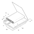
図1は、従来のパウチ形リチウム二次電池の一例であり、パウチが封止される前の状態を示す斜視図である。 FIG. 1 is an example of a conventional pouch-type lithium secondary battery, and is a perspective view showing a state before the pouch is sealed.
従来のパウチ形リチウム二次電池は、電極組立体30と、電極組立体30を収容するパウチ20とを備えている。
A conventional pouch-type lithium secondary battery includes an
図1を参照してパウチ形リチウム二次電池の一般的な製造方法を説明すると、先ず略直方形のパウチ膜の中間を折り畳んで、パウチ20の前面21及び後面22を形成する。後面22には、プレス(Press)加工などを通じて、電極組立体30を収容可能な溝223が形成される。溝223を形成すると、後の工程で電極組立体30を設置しやすくなり、工程を容易にすることができ、溝223を中心にパウチ20の周辺シール部を整えることができるので、パウチをコンパクトに形成することができる。
A general method for manufacturing a pouch-type lithium secondary battery will be described with reference to FIG. 1. First, a
通常の電極組立体30は、正極31、セパレーター33、負極35の順に積層した多層膜を渦状に巻き取ってゼリーロール(Jelly Roll)を形成する。ゼリーロールを巻取形成する時に、正極31と負極35とが短絡することを防ぐために、ロール(Roll)の外部に露呈する電極面、あるいは内部の電極面には、セパレーターが付け加えられる。形成したゼリーロールは、パウチ20の後面22の溝223に置かれ、フランジ状の縁部225において、パウチ20の前面21と後面22とを密着した状態で加熱加圧してパウチの封止を施し、ベアセル電池を形成する。
The
電極組立体30の正極31と負極35とをパウチ20の外部と電気的に連結するために、正極31と負極35の片側には、電極タブ37、38、あるいは電極リ―ドが形成される。これらの電極タブ37、38は、ゼリーロールが巻き取られる方向に対して垂直方向にゼリーロールから突出するように形成され、パウチ20の封止される1辺を介して取り出される。
In order to electrically connect the
パウチの封止過程において、パウチ20の内面のポリマー膜と電極タブ37、38をなす金属との間の接着を強化するために、ポリマー膜の表面に特定の成分を含有させたり、電極タブ37、38がパウチ外装材20との間で短絡することを防止するための絶縁テープ39を封止前に設置することも可能である。
In the sealing process of the pouch, in order to reinforce the adhesion between the polymer film on the inner surface of the
パウチの封止がなされて形成されたベアセル(Bare Cell)に、図示していない保護回路モジュール(PCM: protecting circuit module)やPTC(positive temperature coefficient)のような付属品、あるいは構造体が取り付けられて、コアセル(Core Cell)が形成される。 An accessory or structure such as a protective circuit module (PCM) or positive temperature coefficient (PTC) (not shown) is attached to the bare cell formed by sealing the pouch. Thus, a core cell is formed.
そして、コアセルをハードケースに組み込んで結合させると、完成したハードパック電池が形成される。近年は、省スペース化や工程の単純化のために、別のハードケース無しに、ホットメルト樹脂で回路基板その他の保護装置を取り付けてパウチ電池の長手方向の両端を仕上げて完成させた電池も開発されている。 Then, when the core cell is assembled in a hard case and joined, a completed hard pack battery is formed. In recent years, in order to save space and simplify the process, there are also batteries that have been completed by attaching circuit boards and other protective devices with hot-melt resin and finishing both ends in the longitudinal direction of the pouch battery without a separate hard case. Has been developed.
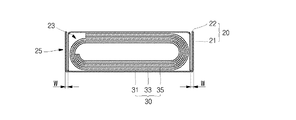
図2は、従来のベアセル状態のパウチ形リチウム二次電池において、電極タブが取り出されていない向い合う2辺の縁を折り曲げた様子を示す斜視図であり、図3は、図2のA−A線に沿って切取したパウチ形リチウム二次電池を示す拡大断面図である。 FIG. 2 is a perspective view showing a state in which the edges of two opposite sides where electrode tabs are not taken out are bent in a conventional bare cell state pouch-type lithium secondary battery, and FIG. It is an expanded sectional view which shows the pouch-type lithium secondary battery cut along the A line.
ベアセル状態で、周辺にシール部25、特に電極タブ37、38が取り出される辺以外の向い合う2辺のシール部25を折り曲げることなく、そのままハードパックを形成すれば、ハードケース内において、これらの部分に相当する幅の分だけ不要な空間が生じてしまう。したがって、ベアセルにおいて、コアパック状態を形成しながら、両側のシール部25を、電極組立体の組み込まれる溝223が形成された側に折り曲げる加工が行われる。パウチをハードケースに入れることなく完成した電池の場合でも、同様にパウチの両側のシール部25を折り曲げて、電池の全幅を減らすようにする。
In the bare cell state, if the hard pack is formed as it is without folding the
したがって、従来のパウチの形成過程では、先ず後面22に溝223が形成される。その溝223の周辺のフランジ部と、溝223に対するカバーをなす前面21の周辺部とが融着されてシールされる。シールされた幅方向の両側のシール部25が、溝223の側に折り曲げられる。
Therefore, in the conventional pouch formation process, the
一方、最近では、パウチ形電池自体のデザイン上の問題、あるいはパウチ形電池が装着される携帯電話などの電気電子機器におけるデザイン上の問題から、パウチの側面を曲面に形成することが、機器のメーカーによって要請されている。また、パウチ電池内の電極組立体の形態も、角の付いた形態ではなく、楕円形やトラック型であるため、パウチ電池の側面を曲面に形成すると、隙間が無く、電極組立体で満たすのに好適であるので、容積に対して電池容量の向上を期待することができる。 On the other hand, recently, due to problems in the design of the pouch-type battery itself or in design of electric and electronic devices such as mobile phones to which the pouch-type battery is attached, it is necessary to form the side surface of the pouch into a curved surface. Requested by the manufacturer. Also, the shape of the electrode assembly in the pouch battery is not an angled form but an oval shape or a track type. Therefore, if the side surface of the pouch battery is formed into a curved surface, there is no gap and the electrode assembly is filled. Therefore, an improvement in battery capacity can be expected with respect to the volume.
ところが、既存の溝を形成したパウチの場合、溝の側壁をなす部分と、溝の周辺のフランジ部とは、溝を形成する深絞り段階で、ほぼ垂直に近い角度をなすことになる。すなわち、角の付いた角部を形成する。シールの後、この部分で両側のシール部を溝側に折り曲げると、既に後面に形成された角の付いた角部の影響で、折曲部は、依然として、角の付いた角部をなすことになる。したがって、見掛け上、パウチの側面は曲面に形成されないので、容積に対して電池容量の面で不利となる。 However, in the case of a pouch in which an existing groove is formed, the portion forming the side wall of the groove and the flange portion around the groove form an angle substantially perpendicular to the deep drawing stage for forming the groove. That is, a corner portion with a corner is formed. After sealing, if the seal part on both sides is folded to the groove side at this part, the bent part will still form a corner with a corner due to the effect of the corner with the corner already formed on the rear surface. become. Therefore, apparently, the side surface of the pouch is not formed into a curved surface, which is disadvantageous in terms of battery capacity with respect to the volume.
また、図3に示すように、ベアセル電池の全幅が、パウチの両側面に形成されたシール部の厚さ(W+ W=2W)の分だけ大きくなってしまう。これにより、幅が一定に定められた電池では、容量を高めるために必要な電極板と電解質の収容空間を、電池の幅方向に増大することは難しい。そして、このような形態を有するパウチコアセルをハードケースに組み付けるなどの後工程において、角の付いた角部の部分が外部と当接して、スクラッチによる損傷が発生しやすい。 Further, as shown in FIG. 3, the entire width of the bare cell battery is increased by the thickness (W + W = 2W) of the seal portions formed on both side surfaces of the pouch. As a result, in a battery having a constant width, it is difficult to increase the electrode plate and electrolyte accommodating space necessary for increasing the capacity in the width direction of the battery. In a subsequent process such as assembling the pouch core cell having such a configuration to the hard case, the corner portions with corners come into contact with the outside, and damage due to scratches is likely to occur.
本発明は、上述したような問題点を解決するためのもので、本発明の目的は、電極組立体を収容するパウチの側壁を曲面に形成することのできるパウチ形電池及びその製造方法を提供することにある。 The present invention is intended to solve the above-described problems, and an object of the present invention is to provide a pouch-type battery in which the side wall of the pouch that accommodates the electrode assembly can be formed into a curved surface, and a method for manufacturing the same. There is to do.
また、本発明の他の目的は、容積に対して電池容量を高めることのできるパウチ形電池及びその製造方法を提供することにある。 Another object of the present invention is to provide a pouch-type battery capable of increasing the battery capacity with respect to the volume and a method for manufacturing the same.
前記目的を達成するための本発明のパウチ形電池は、第1の電極と、第2の電極と、これらの電極との間に介在されるセパレーターとを積層して巻き取られてなる電極組立体と、パウチ形ケースとからなり、パウチ形ケースは、前面部と後面部とに分けられる。ここで、後面部は、電極組立体が設置される溝の側壁と、溝の底面と、溝の周辺の向い合う一対の第1の側辺から延設されたフランジ部とを含んでおり、前面部は溝の周辺の向い合う一対の第2の側辺から延設され、溝に設置された電極組立体を覆うように曲げられた2つの延設部を有する。そして、2つの延設部の端部を重ねて融着し、前記フランジ部と前面部とが重なる部分も融着することで、全体的にシールされたパウチを形成するようになる。 In order to achieve the above object, a pouch-type battery according to the present invention comprises an electrode assembly formed by laminating and winding a first electrode, a second electrode, and a separator interposed between these electrodes. It consists of a solid body and a pouch-type case, and the pouch-type case is divided into a front part and a rear part. Here, the rear surface portion includes a side wall of the groove where the electrode assembly is installed, a bottom surface of the groove, and a flange portion extending from a pair of first side edges facing each other around the groove, The front surface portion has two extending portions that are extended from a pair of second sides facing each other around the periphery of the groove, and are bent so as to cover the electrode assembly installed in the groove. Then, the end portions of the two extending portions are overlapped and fused, and the portion where the flange portion and the front portion overlap is also fused, thereby forming a pouch that is totally sealed.
一方、本発明のパウチ形電池において、延設部の2つの端部を重ねて融着する際には、2つの端部に一定の引張力を印加して、互いに引っ張る力が作用するようにすることが望ましい。これにより、溝の2つの側壁は、電極組立体の該当部分の外周面に対応した曲面形状に形成することが容易になり、パウチベアセルにおいて、パウチケースには電極組立体の外周縁部を取り囲む方向に引張力が印加された状態になる。 On the other hand, in the pouch-type battery of the present invention, when the two ends of the extending portion are overlapped and fused, a constant tensile force is applied to the two ends so that the pulling forces act on each other. It is desirable to do. Accordingly, the two side walls of the groove can be easily formed into a curved shape corresponding to the outer peripheral surface of the corresponding part of the electrode assembly. In the pouch bear cell, the pouch case surrounds the outer peripheral edge of the electrode assembly. A tensile force is applied to the.
本発明のパウチ形電池の製造方法は、溝と、溝の周辺の向い合う2つのフランジ部と、向い合う2つの延設部とを有するパウチ外装材を用意する段階と、巻取型の電極組立体を用意する段階と、電極組立体の2本の電極タブがフランジ部を横切って外部に取り出されるように、電極組立体をパウチ外装材の溝に設置する段階と、電極組立体を覆うように前記2つの延設部を曲げて、その端部を重なるようにして融着し、前面シール部を形成する段階と、フランジ部と2つの延設部とが重なる部分の少なくとも一方を融着する段階とを含むことを特徴とする。 A method of manufacturing a pouch-type battery according to the present invention includes a step of preparing a pouch exterior material having a groove, two flange portions facing each other around the groove, and two extending portions facing each other, and a winding-type electrode Preparing the assembly, installing the electrode assembly in the groove of the pouch exterior so that the two electrode tabs of the electrode assembly are taken out across the flange, and covering the electrode assembly Bending the two extending portions and fusing the end portions so as to overlap each other to form a front seal portion and melting at least one of the overlapping portions of the flange portion and the two extending portions. A stage of wearing.
本発明の方法において、フランジ部と2つの延設部とが重なる部分の少なくとも一方を融着する段階に続いて、フランジ部と2つの延設部とが重なる部分のうち、開放された部分を介して電解液を注入する段階と、開放された部分をシールする段階と、初期の充放電を施す段階とを更に含むようにすることができる。 In the method of the present invention, following the step of fusing at least one of the overlapping portions of the flange portion and the two extending portions, an open portion of the overlapping portion of the flange portion and the two extending portions is defined. The method may further include a step of injecting an electrolyte solution through the step, a step of sealing the opened portion, and a step of performing initial charge / discharge.
本発明によれば、従来のパウチ型二次電池とは異なり、電極組立体を収容するパウチの側壁を曲面に形成することが可能になり、曲面が要請される電気電子機器に対して容易に装着することができる。 According to the present invention, unlike the conventional pouch-type secondary battery, the side wall of the pouch that accommodates the electrode assembly can be formed into a curved surface, which can be easily applied to electric and electronic devices that require a curved surface. Can be installed.
また、パウチの側壁を曲面にすることにより、楕円形やトラック状の横断面を有する電極組立体を、隙間無しに収容することができ、パウチのシール部が側面に位置していた従来と比べて、パウチの幅を減らすことができ、容積に対して電池容量を高めることが可能となる。 In addition, by making the side wall of the pouch curved, the electrode assembly having an elliptical or track-like cross section can be accommodated without a gap, and the sealing part of the pouch is positioned on the side as compared with the conventional case. Thus, the width of the pouch can be reduced, and the battery capacity can be increased with respect to the volume.
また、電極組立体の上面や下面に対して直接電解液を注入できるので、電解液の注入に要する時間を減らすことが可能となる。 In addition, since the electrolytic solution can be directly injected into the upper and lower surfaces of the electrode assembly, the time required for the injection of the electrolytic solution can be reduced.
以下、図面を参照しながら、本発明の実施例に基づいて本発明をより詳細に説明する。 Hereinafter, the present invention will be described in more detail based on embodiments of the present invention with reference to the drawings.
図4乃至図7は、本発明の方法でパウチ形リチウム二次電池を製造するための主要な段階を示す工程図である。 4 to 7 are process diagrams showing main steps for manufacturing a pouch-type lithium secondary battery by the method of the present invention.
図4は、溝が形成されたパウチ外装材40に電極組立体30が位置している様子を示す図である。溝43は、底面及び4つの側面を有するパウチの壁体からなる。底面と側面とが出会う角部は、滑らかな曲面をなすように、深絞りを通じて溝43を形成する。溝43の平面形状は矩形からなり、短い2つの側辺(第1の側辺)には、溝43の周辺に設けられたフランジ部42、44が形成されている。溝43の長い2つの側辺(第2の側辺)と、フランジ部42、44の両側には、2つの延設部46、48が位置する。2つの延設部46、48は、同じ幅で形成されている。このような形態は、平らな四角形のパウチ外装材40に対して溝43の部分を深絞り加工で形成することにより実現することができる。
FIG. 4 is a diagram illustrating a state in which the
ここで、パウチをなす多層膜は、およそアルミニウム(Al)のような金属材からなる芯部と、芯部のパウチの内側面上に形成された熱融着層と、芯部のパウチの外側面上に形成された絶縁膜とからなる。熱融着層は、ポリマー樹脂である変性ポリプロフィレン、例えばCPP(Casted Polypropylene)を使用して接着層として働き、絶縁膜は、ナイロン(Nylon)やポリエチレンテレフタレート(PET)のような樹脂材で形成することができる。 Here, the multilayer film forming the pouch is composed of a core part made of a metal material such as aluminum (Al), a heat-sealing layer formed on the inner side surface of the core part pouch, and an outer part of the core part pouch. And an insulating film formed on the side surface. The heat-sealing layer works as an adhesive layer using a modified polypropylene that is a polymer resin, such as CPP (Casted Polypropylene), and the insulating film is formed of a resin material such as nylon (Nylon) or polyethylene terephthalate (PET) can do.
電極組立体30は、通常の角形電池の電極組立体と同様に、楕円形またはスタジアム型に形成される。このような電極組立体30は、セパレーター、第1の電極、セパレーター、第2の電極、あるいは、第1の電極、セパレーター、第2の電極、セパレーターの順に層状構造を有するように、2本の電極とセパレーターとをマンドレル(Mandrel)を用いて巻取して形成することができる。
The
各電極は、集電体をなす金属箔や金属メッシュの少なくとも一面に活物質を含むスラリ層を形成し、集電体の一部に外部への電気的な接続のためのタブを結合して形成される。 Each electrode is formed by forming a slurry layer containing an active material on at least one surface of a metal foil or metal mesh forming a current collector, and connecting a tab for electrical connection to the outside to a part of the current collector. It is formed.
この実施例において、第1の電極は、アルミニウム(Al)材質からなる集電体に、一定の長さだけ突出したアルミニウムの第1の電極タブ37が溶接されている。第2の電極には、銅材質の集電体に、一般的にニッケル(Ni)材質からなり、一定の長さだけ突出した第2の電極タブ38が溶接されている。第1の電極タブ37及び第2の電極タブ38とパウチ外装材40との間の短絡を防止するための絶縁テープが更に備えられている。
In this embodiment, a
第1の電極タブ37及び第2の電極タブ38は、パウチ外装材40の上フランジ部42を介して外部に取り出され、パウチの外側で保護回路モジュール(図示せず)と電気的に連結される。
The
第1の電極集電体の少なくとも一面に形成されるスラリの活物質としては、カルコゲナイド(Chalcogenide)化合物、例えば、LiCoO2、LiMn2O4、LiNiO2、LiNi1-XCoXO2(0<x<1)、LiMnO2などの複合金属酸化物を用いることができる。第2の電極集電体の少なくとも一面に形成されるスラリの活物質としては、炭素(C)系物質、Si、Sn、スズ酸化物、スズ合金複合体(Composite tin alloys)、遷移金属酸化物、リチウム金属ナイトライド、または、リチウム金属酸化物などを用いることができる。 The slurry active material formed on at least one surface of the first electrode current collector includes a chalcogenide compound such as LiCoO 2 , LiMn 2 O 4 , LiNiO 2 , LiNi 1-X Co X O 2 (0 <x <1), composite metal oxides such as LiMnO 2 can be used. Slurry active materials formed on at least one surface of the second electrode current collector include carbon (C) materials, Si, Sn, tin oxide, composite tin alloys, and transition metal oxides. Lithium metal nitride or lithium metal oxide can be used.
電極タブ37、38が取り出される部分では、電極タブ37、38が上フランジ部42を横切ることになる。この時、パウチ膜の金属箔を通じて互いに短絡することがないように、またパウチのシールに役立つように、電極タブ37、38が取り出される部分には樹脂テープ(絶縁テープ)が貼り付けられている。
In the part where the
図4の状態において、パウチ外装材40の溝43及びフランジ42、44からなる部分と、2つの延設部46、48との間の境界に沿って、延設部46、48が溝43に置かれた電極組立体30を覆うように折り畳まれる。そして、折り畳まれた延設部46と延設部48が互いに出会う2つの端部461、481の融着と、電極タブ37、38が取り出される上フランジ部42に対する融着とが行われて図5に示す状態となり、上シール部52及び前面シール部51が形成される。延設部46、48の2つの端部461、481は、図5aに示すように、パウチ膜の内側に位置する熱融着性の樹脂層が相対向するようにして融着を施し、図5bに示すように融着された前面シール部51を折り曲げて、パウチの他の延設部に当接するようにする。実施例によっては、2つの延設部46、48の融着されるべき端部461、481を対向させた後、融着する前に、これらの端部を、一旦パウチの前面部に当接するように折り曲げ、この状態において、端部461、481を互いに融着することもできる。2つの端部461、481の融着と、電極タブ37、38が取り出される上フランジ部42に対する融着は、互いに順序を逆にして行ってもよいし、また同時に行ってもよい。
In the state shown in FIG. 4, the extending
一方、延設部46、48の2つの端部461、481を融着させる際には、2つの端部461、481をパウチの幅の中央側に引っ張って融着を施す。2つの端部461、481が引っ張られる過程では、2つの端部461、481は、元々パウチの幅の外側に向かっていたものを、パウチ幅の内側に向かうようにする。したがって、パウチ外装材40に形成された溝43の長い側辺と延設部46、48とが接する部分の角の付いた形状が広がるようになる。同時に、溝43の内部に設置されている電極組立体30の外面が支持基準面となり、パウチ溝43の長い側辺の部分に電極組立体30の外面のような形状をした曲面が形成されながら、パウチベアセルの側壁53は、全体として曲面をなすようになる。
On the other hand, when fusing the two
図6を参照すれば、電極タブ37、38が取り出される第1のシール部(上シール部)52の反対側にも第2のシール部(下シール部)があり、この第2のシール部には、図5の状態において、熱融着が行われていないので、内部の電極組立体30に電解液60を供給する通路になり得る。開放された第2のシール部を介して、パウチの内部に電解液60が注入される。
Referring to FIG. 6, there is a second seal portion (lower seal portion) on the opposite side of the first seal portion (upper seal portion) 52 from which the
従来のパウチ形リチウム電池において、電解液の注入は、パウチ溝43の長い側辺、すなわち電極組立体30の横から行われていた。この場合、パウチに注入された電解液は、電極板に遮られて、電極組立体30の内部に流入し難かった。したがって、電解液は、一旦電極組立体30の上下面へ移動し、上下面から、セパレーターと電極との間の隙間を介して、電極組立体30の内部に流れ込む。しかし、本実施例では、開放されたフランジ部側から電解液60を注入するので、電解液が注入される方向に電極板とセパレーターとの間の隙間が見える電極組立体30の上面、あるいは下面が現れるようになる。したがって、電解液が容易に電極組立体30内に流入することができる。別の実施例では、電極タブ37、38が取り出される第1のシール部52の一部を開放した状態にし、反対側の第2のシール部をシールして電解液がパウチ50の第1のシール部52を介して注入されるようにすることもできる。
In the conventional pouch-type lithium battery, the electrolyte is injected from the long side of the
次に、図7に示すように、電解液が注入された状態において、開放されたフランジ部に対する熱融着を行って、パウチの下シール部57'を形成し、パウチが完全に外部から封止されるようにする。下シール部57'は、パウチ50の下面(図6の55)をカバーするように折り曲げられて下シール部57を形成することになる。この時、下シール部57からなるカバーは、パウチ50を二重の多層膜で保護するので、一重の多層膜で形成されたパウチ形ケースの下面部分を補って保護する役割を果たすことができる。
Next, as shown in FIG. 7, in the state in which the electrolytic solution is injected, heat sealing is performed on the opened flange portion to form a
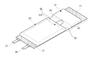
図8及び図9は、本発明の他の実施例に係るパウチ形電池の製造工程を示す工程図である。図7の実施例と比較すると、上部にある第1のシール部72の反対側に第2のシール部64が長く延設され、延設された部分の一部には、ガス室81が存在する。電極組立体30が置かれる溝63の部分とガス室81の部分とは、第2のシール部64に形成された連結溝85を通じて連結される。連結溝85は、電解液が注入される通路、及びガスをガス室81へ捕集する通路としての役割を果たしている。連結溝85を形成するために、溝63を構成する4つの側壁のうち、下面55は、一部が除去された形状を有する。下面55を基準にして、当該除去部は、一種の溝と理解することができ、以下、開口部552として説明する。開放された下フランジ部64を介して電解液を注入した後、下フランジ部64の下側の端部77を融着してパウチをシールする。初期充電を通じて発生したガスは、下フランジ部64に形成されたガス室81に集まるようになる。
8 and 9 are process diagrams showing a process for manufacturing a pouch-type battery according to another embodiment of the present invention. Compared with the embodiment of FIG. 7, the
この後、パウチにおいて、溝63に隣接した下フランジ部64の最終の融着部分79に対する融着を施して、下シール部を形成する。最終の融着により、初期の充放電時に生じたガスが集まったガス室81と、電極組立体30が置かれた溝63とが空間的に分離される。第2のフランジ部64のうち、最終の融着部分79よりも下方にある部分を除去する。図9に示すように、最終の融着部分79をパウチの下面側に折り曲げることで、最終の融着部分である下シール部79により、パウチの下面を保護できるようにする。この時、下シール部79が折り畳まれることから、パウチは、長さが低減され、完成した電池の容積に比べて電池の容量を高めることができるようになる。
Thereafter, in the pouch, the
一方、図8で示した実施例の開口部552を、ガス室が設けられていない図4乃至図7の実施例のような場合でも形成することができる。開口部は、電解液を注入する段階で、電解液をパウチ形ケースの前面部に沿って注入するので、電解液の注入が偏在することを防ぐ役割を果たす。すなわち、開口部を通じて露出した電極組立体の下面の全体に電解液を均一に供給することができ、これによって電極組立体の下面の全体から露出した電極とセパレーターとの間の隙間に沿って、電解液を電極組立体の内部に染み込ませる役割を果たす。
On the other hand, the
一方、図5や図9に示すように形成されたパウチベアセルにおいて、前面部に位置する前面シール部51は、パウチの横方向(第1の側辺が伸びている方向)を基準にして、パウチの外部に取り出されている2本の電極タブ37、38の間に位置することが望ましく、パウチの中央部に位置するようにする。たとえば、電極タブ37、38は、およそ0.1mm程度の厚さを有し、パウチの横方向において、電極組立体30にタブを形成するためには、電極とセパレーターとの間の空間、及び電極組立体とパウチ壁体との間の空間は足りない。したがって、電極タブ37、38は、互いに重ならないように、通常電極組立体30の離隔した位置に形成される。そして、電極組立体30の幅方向の両端部は、屈曲した部分をなしているので、電極組立体30内で電極間の空間が小さい。一方、電極タブが位置しない残りの部分、電極タブ37と電極タブ38との間の部分は、相対的に電極間の空間に余裕がある。したがって、パウチの外部において、前面シール部51がこの部分に配置されるようにすると、二次電池の実質的な厚さを殆ど増加させることがないように形成することができる。前面シール部51が作られる段階で、パウチ50の狭い側壁53は、内部の電極組立体30の外面に沿って曲面を形成するようになる。
On the other hand, in the pouch bear cell formed as shown in FIGS. 5 and 9, the
次に、本発明の一実施形態に係るパウチ形電池の製造方法を説明する。
まず、本実施形態に係るパウチ形電池の製造方法では、パウチ外装材に溝43と、この溝43の周辺で向い合う2つのフランジ部42、44と、向い合う2つの延設部46、48とを形成し、このような形状のパウチ外装材40を用意する。また、その一方で電極タブ37、38が形成された2本の電極と、2本の電極間に介在されるセパレーターとを有する巻取型の電極組立体30も用意する。
そして、用意したパウチ外装材40と電極組立体30とを使い、電極タブ37、38が、フランジ部のうちの1つを横切って外部に取り出されるように、溝43に電極組立体30を設置し、設置した電極組立体30を覆うようにして2つの延設部46、48を曲げて、その端部461、481が重なるようにして融着し、前面シール部51を形成する。
さらに、フランジ部42、44と2つの延設部46、48とが重なる部分のうちの少なくとも一方を融着し、融着されていない開放された部分を介して電解液を注入する。
この後、開放された部分をシールして電極タブ37、38に外部電気端子を接続し、初期充電を施すことで本実施形態に係るパウチ形電池の製造方法は終了する。
本発明では、リチウム二次電池を主な実施例として説明してきたが、本発明は、初期の充放電やガス室の形成の例を除いて、全てのパウチ形電池に適用可能である。
Next, a method for manufacturing a pouch-type battery according to an embodiment of the present invention will be described.
First, in the method for manufacturing a pouch-type battery according to the present embodiment, a
Then, using the prepared
Further, at least one of the overlapping portions of the
Thereafter, the open portion is sealed, external electric terminals are connected to the
In the present invention, the lithium secondary battery has been described as a main embodiment, but the present invention is applicable to all pouch-type batteries except for the example of initial charge / discharge and gas chamber formation.
30 電極組立体
37 第1の電極タブ
38 第2の電極タブ
40 パウチ外装材
43 溝
42、44 フランジ部
46、48 延設部
52 シール部
461、481 端部
30
Claims (14)
前記電極組立体が設置される溝の側壁と、前記溝の底面と、前記溝の周辺の向い合う一対の第1の側辺から延設されたフランジ部とを含む後面部と、
前記溝の周辺の向い合う一対の第2の側辺から延設され、前記溝に設置された前記電極組立体を覆うように曲げられた2つの延設部を含む前面部とを有し、
前記溝をなす4つの前記側壁のうちの前記第2の側辺に連結される2つの前記側壁が曲面からなり、
前記2つの延設部の端部を重ねて融着して前面シール部を形成し、前記フランジ部と前記前面部とが重なる部分を融着して上シール部及び下シール部を形成するパウチ形ケースとを備えるパウチ形電池であって、
前記フランジ部と前記2つの延設部とが重なる部分のうち、開放された部分を介して電解液を注入する段階と、
前記開放された部分をシールする段階と、
前記電極タブに外部電気端子を接続して初期充電を施す段階と
を含むことを特徴とするパウチ形電池の製造方法。 An electrode assembly formed by laminating and winding a first electrode and a second electrode each having an electrode tab, and a separator interposed between the first electrode and the second electrode;
A rear surface portion including a side wall of the groove in which the electrode assembly is installed, a bottom surface of the groove, and a flange portion extending from a pair of first sides facing the periphery of the groove;
A front portion including two extending portions that are extended from a pair of second sides facing each other around the groove and are bent so as to cover the electrode assembly disposed in the groove;
Of the four side walls forming the groove, the two side walls connected to the second side are curved surfaces,
A pouch that forms a front seal portion by overlapping and fusing the ends of the two extending portions, and forms an upper seal portion and a lower seal portion by fusing portions where the flange portion and the front portion overlap. A pouch-type battery comprising a shape case ,
Of the portion where the flange portion and the two extending portions overlap, injecting the electrolyte solution through the open portion;
Sealing the open portion;
Connecting an external electrical terminal to the electrode tab to perform initial charging;
The manufacturing method of the pouch-type battery characterized by including.
前記前面シール部は、前記電極タブが取り出されている位置の間に形成されていることを特徴とする請求項1から請求項5 のいずれか1項に記載のパウチ形電池の製造方法。 The electrode tabs are removed from positions separated from each other;
The method for manufacturing a pouch-type battery according to claim 1, wherein the front seal portion is formed between positions where the electrode tabs are taken out.
前記初期充電を施す段階の後に前記下フランジ部の前記溝に近い側の端部をシールして下シール部を形成し、前記下シール部より下側の部分を除去する段階を、更に含むことを特徴とする請求項1に記載のパウチ形電池の製造方法。 In the step of sealing the opened portion, only the end of the flange portion far from the groove of the lower flange portion where the electrode tab is not taken out is sealed,
The method further includes sealing the end of the lower flange portion closer to the groove to form a lower seal portion and removing a portion below the lower seal portion after the initial charging step. The method for manufacturing a pouch-type battery according to claim 1 .
前記下シール部より下側の部分を除去する段階では、前記ガス室が形成された部分を除去することを特徴とする請求項10に記載のパウチ形電池の製造方法。 In the stage of preparing the pouch exterior material, a gas chamber different from the groove is provided in the lower flange portion,
11. The method of manufacturing a pouch-type battery according to claim 10 , wherein in the step of removing a portion below the lower seal portion, a portion where the gas chamber is formed is removed.
前記下シール部を折り曲げて前記パウチ形ケースの下面に接するようにする段階を更に含むことを特徴とする請求項10から請求項12のいずれか1項に記載のパウチ形電池の製造方法。 Following the step of removing the portion below the lower seal portion,
The method for manufacturing a pouch-type battery according to any one of claims 10 to 12 , further comprising a step of bending the lower seal portion so as to be in contact with a lower surface of the pouch-type case.
前記フランジ部と前記2つの延設部とが重なる部分の少なくとも一方を融着する段階とを同時に行うことを特徴とする請求項10から請求項13のいずれか1項に記載のパウチ形電池の製造方法。 Forming the front seal portion;
The pouch-type battery according to any one of claims 10 to 13 , wherein the step of fusing at least one of the overlapping portions of the flange portion and the two extending portions is performed at the same time. Production method.
Applications Claiming Priority (1)
| Application Number | Priority Date | Filing Date | Title |
|---|---|---|---|
| KR1020050134553A KR100824897B1 (en) | 2005-12-29 | 2005-12-29 | Pouch type Battery and Method of Forming th Same |
Publications (2)
| Publication Number | Publication Date |
|---|---|
| JP2007184267A JP2007184267A (en) | 2007-07-19 |
| JP4559405B2 true JP4559405B2 (en) | 2010-10-06 |
Family
ID=37943890
Family Applications (1)
| Application Number | Title | Priority Date | Filing Date |
|---|---|---|---|
| JP2006342802A Active JP4559405B2 (en) | 2005-12-29 | 2006-12-20 | Pouch-type battery and manufacturing method thereof |
Country Status (5)
| Country | Link |
|---|---|
| US (1) | US8936653B2 (en) |
| EP (1) | EP1804313B1 (en) |
| JP (1) | JP4559405B2 (en) |
| KR (1) | KR100824897B1 (en) |
| CN (1) | CN1992381B (en) |
Families Citing this family (39)
| Publication number | Priority date | Publication date | Assignee | Title |
|---|---|---|---|---|
| KR20060112731A (en) | 2005-04-27 | 2006-11-02 | 삼성에스디아이 주식회사 | Secondary battery |
| JP4559406B2 (en) * | 2005-12-29 | 2010-10-06 | 三星エスディアイ株式会社 | Pouch-type battery |
| KR100913836B1 (en) * | 2006-09-18 | 2009-08-26 | 주식회사 엘지화학 | Pouch-typed Secondary Battery with Improved Safety |
| CN101488566B (en) * | 2008-01-15 | 2011-08-17 | 财团法人工业技术研究院 | Soft packing cell and air tight type conductive connection structure and assembling process |
| KR101002468B1 (en) | 2008-07-01 | 2010-12-17 | 삼성에스디아이 주식회사 | Pouch-type Lithium Secondary Battery |
| KR101042766B1 (en) * | 2009-02-05 | 2011-06-20 | 삼성에스디아이 주식회사 | Battery pack and manufacturing method the same |
| EP2273162B1 (en) | 2009-07-06 | 2019-01-09 | Carl Freudenberg KG | Sealing frame for use in a battery |
| US8623537B2 (en) * | 2009-08-18 | 2014-01-07 | Samsung Sdi Co., Ltd. | Rechargeable battery and battery module |
| KR20110053835A (en) * | 2009-11-16 | 2011-05-24 | 삼성에스디아이 주식회사 | Lithium polymer secondary battery |
| KR20110053836A (en) * | 2009-11-16 | 2011-05-24 | 삼성에스디아이 주식회사 | Lithium polymer secondary battery |
| GB2482324B (en) * | 2010-07-30 | 2018-02-14 | Energy Control Ltd | Battery assembly formed by plural soft packing secondary batteies |
| JP5987336B2 (en) * | 2011-03-25 | 2016-09-07 | 日本電気株式会社 | Secondary battery |
| CN103503196B (en) | 2011-06-30 | 2016-02-03 | 株式会社Lg化学 | There is the secondary cell of the contact resistance of improvement |
| JP5743791B2 (en) * | 2011-08-02 | 2015-07-01 | 三洋電機株式会社 | Power supply device and vehicle equipped with power supply device |
| KR101441645B1 (en) * | 2011-08-08 | 2014-09-23 | 주식회사 엘지화학 | Pouch film for secondary battery and method for manufacturing secondary battery using the same |
| US8989821B2 (en) | 2011-08-31 | 2015-03-24 | Apple Inc. | Battery configurations for electronic devices |
| KR101893958B1 (en) | 2011-12-09 | 2018-08-31 | 삼성에스디아이 주식회사 | Secondary battery |
| US9343716B2 (en) | 2011-12-29 | 2016-05-17 | Apple Inc. | Flexible battery pack |
| US9017852B2 (en) | 2012-03-02 | 2015-04-28 | Samsung Sdi Co., Ltd. | Secondary battery |
| KR20140015769A (en) * | 2012-07-24 | 2014-02-07 | 삼성에스디아이 주식회사 | Rechargable battery |
| US9812680B2 (en) | 2012-08-30 | 2017-11-07 | Apple Inc. | Low Z-fold battery seal |
| JP6103342B2 (en) * | 2012-09-13 | 2017-03-29 | 株式会社Gsユアサ | Electricity storage element |
| US9136510B2 (en) * | 2012-11-26 | 2015-09-15 | Apple Inc. | Sealing and folding battery packs |
| US9593969B2 (en) | 2013-12-27 | 2017-03-14 | Apple Inc. | Concealed electrical connectors |
| DE102014201157A1 (en) * | 2014-01-23 | 2015-07-23 | Robert Bosch Gmbh | Electrochemical energy storage |
| US9479007B1 (en) | 2014-02-21 | 2016-10-25 | Apple Inc. | Induction charging system |
| US20150255776A1 (en) | 2014-03-06 | 2015-09-10 | Apple Inc. | Battery Pack System |
| US9455582B2 (en) | 2014-03-07 | 2016-09-27 | Apple Inc. | Electronic device and charging device for electronic device |
| JP6264196B2 (en) * | 2014-05-30 | 2018-01-24 | 三洋電機株式会社 | Prismatic secondary battery |
| US9917335B2 (en) | 2014-08-28 | 2018-03-13 | Apple Inc. | Methods for determining and controlling battery expansion |
| KR101811837B1 (en) | 2015-01-16 | 2017-12-22 | 주식회사 엘지화학 | Pouch-Type Battery Cell Having Residue Sealing Portion |
| US10637017B2 (en) | 2016-09-23 | 2020-04-28 | Apple Inc. | Flexible battery structure |
| US10686228B2 (en) | 2016-12-14 | 2020-06-16 | Pacesetter, Inc. | Pouch battery for use in implantable electronic devices |
| KR102334022B1 (en) * | 2018-11-02 | 2021-12-02 | 주식회사 엘지에너지솔루션 | Pouch-type Secondary Battery Having Groove for Replenishing an electrolyte |
| KR20200068415A (en) | 2018-12-05 | 2020-06-15 | 에스케이이노베이션 주식회사 | Pouch film and secondary comprising the same |
| KR102455471B1 (en) * | 2019-02-18 | 2022-10-14 | 주식회사 엘지에너지솔루션 | Battery cell, battery module comprising the battery cell, battery rack comprising the battery module and energy storage system comprising the battery rack |
| KR102446570B1 (en) * | 2019-05-03 | 2022-09-23 | 주식회사 엘지에너지솔루션 | Danger sensing battery cell |
| KR102468395B1 (en) * | 2019-07-22 | 2022-11-16 | 주식회사 엘지에너지솔루션 | Separator Sealing Device and Sealing Method to Prevent Folding of separator |
| EP4309228A2 (en) | 2021-09-27 | 2024-01-24 | QuantumScape Battery, Inc. | Electrochemical stack and method of assembly thereof |
Citations (4)
| Publication number | Priority date | Publication date | Assignee | Title |
|---|---|---|---|---|
| JPH10308240A (en) * | 1997-05-09 | 1998-11-17 | Sanyo Electric Co Ltd | Manufacture of battery |
| JP2000215862A (en) * | 1999-01-25 | 2000-08-04 | Sanyo Electric Co Ltd | Thin sealed battery using laminate enclosure |
| JP2000285877A (en) * | 1999-03-30 | 2000-10-13 | Japan Storage Battery Co Ltd | Nonaqueous electrolyte secondary battery |
| JP2005166650A (en) * | 2003-11-14 | 2005-06-23 | Sony Corp | Battery pack |
Family Cites Families (20)
| Publication number | Priority date | Publication date | Assignee | Title |
|---|---|---|---|---|
| JPS62154550A (en) | 1985-12-27 | 1987-07-09 | Matsushita Electric Ind Co Ltd | Sealed lead-acid battery |
| DE3732037A1 (en) | 1986-12-19 | 1988-06-23 | Shin Kobe Electric Machinery | DENSITY LEAD BATTERY AND METHOD FOR THE PRODUCTION THEREOF |
| JP3445065B2 (en) | 1996-07-30 | 2003-09-08 | 東芝電池株式会社 | Outer housing for battery pack and battery pack |
| WO1999040634A1 (en) | 1998-02-05 | 1999-08-12 | Dai Nippon Printing Co., Ltd. | Sheet for cell case and cell device |
| US6797429B1 (en) * | 1998-11-06 | 2004-09-28 | Japan Storage Battery Co, Ltd. | Non-aqueous electrolytic secondary cell |
| JP2000164176A (en) * | 1998-11-26 | 2000-06-16 | Tokai Rubber Ind Ltd | Bag body for thin battery |
| DE60036354T2 (en) | 1999-04-08 | 2008-05-29 | Dai Nippon Printing Co., Ltd. | Laminated multilayer structure for lithium battery packaging |
| JP4438137B2 (en) * | 1999-09-14 | 2010-03-24 | 株式会社ジーエス・ユアサコーポレーション | Battery manufacturing method |
| GB0029625D0 (en) * | 2000-12-05 | 2001-01-17 | Danionics As | Electrochemical cells and their packaging |
| JP3751834B2 (en) * | 2001-02-05 | 2006-03-01 | 日本電気株式会社 | Film seal type non-aqueous electrolyte battery |
| JP2003077435A (en) | 2001-09-06 | 2003-03-14 | Gs-Melcotec Co Ltd | Battery pack |
| US20040048149A1 (en) * | 2001-10-30 | 2004-03-11 | Oliver Gross | Battery packaging construction |
| JP3811388B2 (en) * | 2001-11-09 | 2006-08-16 | 松下電器産業株式会社 | battery |
| US20030129488A1 (en) * | 2002-01-09 | 2003-07-10 | Gross Oliver J. | Planar battery and method of sealing |
| KR100858799B1 (en) * | 2002-06-29 | 2008-09-17 | 삼성에스디아이 주식회사 | Pouch type secondary battery |
| TWI300637B (en) | 2002-09-27 | 2008-09-01 | Sony Corp | Battery pack and method for producing same |
| JP4403375B2 (en) * | 2003-08-28 | 2010-01-27 | パイオニクス株式会社 | Thin pack battery |
| KR100560158B1 (en) | 2003-09-29 | 2006-03-16 | 주식회사 코캄 | Lithium secondary battery with high safety and manufacturing method thereof |
| JP4488717B2 (en) | 2003-10-31 | 2010-06-23 | 三洋電機株式会社 | Pack battery |
| US7556885B2 (en) * | 2003-11-14 | 2009-07-07 | Sony Corporation | Battery pack |
-
2005
- 2005-12-29 KR KR1020050134553A patent/KR100824897B1/en active IP Right Grant
-
2006
- 2006-12-14 US US11/638,376 patent/US8936653B2/en active Active
- 2006-12-20 JP JP2006342802A patent/JP4559405B2/en active Active
- 2006-12-28 EP EP06127267A patent/EP1804313B1/en active Active
- 2006-12-29 CN CN2006101717816A patent/CN1992381B/en active Active
Patent Citations (4)
| Publication number | Priority date | Publication date | Assignee | Title |
|---|---|---|---|---|
| JPH10308240A (en) * | 1997-05-09 | 1998-11-17 | Sanyo Electric Co Ltd | Manufacture of battery |
| JP2000215862A (en) * | 1999-01-25 | 2000-08-04 | Sanyo Electric Co Ltd | Thin sealed battery using laminate enclosure |
| JP2000285877A (en) * | 1999-03-30 | 2000-10-13 | Japan Storage Battery Co Ltd | Nonaqueous electrolyte secondary battery |
| JP2005166650A (en) * | 2003-11-14 | 2005-06-23 | Sony Corp | Battery pack |
Also Published As
| Publication number | Publication date |
|---|---|
| EP1804313A3 (en) | 2009-10-14 |
| KR20070071247A (en) | 2007-07-04 |
| US8936653B2 (en) | 2015-01-20 |
| EP1804313B1 (en) | 2012-05-16 |
| EP1804313A2 (en) | 2007-07-04 |
| JP2007184267A (en) | 2007-07-19 |
| KR100824897B1 (en) | 2008-04-23 |
| CN1992381A (en) | 2007-07-04 |
| US20070154794A1 (en) | 2007-07-05 |
| CN1992381B (en) | 2011-04-06 |
Similar Documents
| Publication | Publication Date | Title |
|---|---|---|
| JP4559405B2 (en) | Pouch-type battery and manufacturing method thereof | |
| JP4559406B2 (en) | Pouch-type battery | |
| JP5281836B2 (en) | Electrode assembly and secondary battery using the same | |
| US7682735B2 (en) | Pouch type lithium secondary battery and method of fabricating the same | |
| US7528573B2 (en) | Rechargeable battery having bare cell and protection circuit module | |
| US8524392B2 (en) | Pouch-type rechargeable battery and its method of manufacture | |
| JP4620552B2 (en) | Secondary battery having jelly roll type electrode assembly | |
| US8936860B2 (en) | Battery pack with reinforcing member | |
| US20090258290A1 (en) | Pouch type lithium secondary battery | |
| JP4823145B2 (en) | Battery pack | |
| KR100670438B1 (en) | Pouch type lithium secondary battery | |
| KR100731436B1 (en) | Pouch type Lithium Secondary Battery | |
| KR20090038117A (en) | Pouch type battery | |
| KR101264432B1 (en) | Battery Pack Including Out-Case With A Step | |
| KR101264434B1 (en) | Battery Pack including out-case assembled on long-side of bare cell | |
| KR100580767B1 (en) | Pouch Type Lithium Ion Polymer Battery | |
| EP2343753B1 (en) | Battery pack | |
| KR20060034508A (en) | Pouch type lithium secondary battery | |
| KR20060059691A (en) | Can type rechargeable battery | |
| JP2006278326A (en) | Pouch-like lithium secondary cell and its manufacturing method |
Legal Events
| Date | Code | Title | Description |
|---|---|---|---|
| A131 | Notification of reasons for refusal |
Free format text: JAPANESE INTERMEDIATE CODE: A131 Effective date: 20100302 |
|
| A521 | Request for written amendment filed |
Free format text: JAPANESE INTERMEDIATE CODE: A523 Effective date: 20100531 |
|
| TRDD | Decision of grant or rejection written | ||
| A01 | Written decision to grant a patent or to grant a registration (utility model) |
Free format text: JAPANESE INTERMEDIATE CODE: A01 Effective date: 20100629 |
|
| A01 | Written decision to grant a patent or to grant a registration (utility model) |
Free format text: JAPANESE INTERMEDIATE CODE: A01 |
|
| A61 | First payment of annual fees (during grant procedure) |
Free format text: JAPANESE INTERMEDIATE CODE: A61 Effective date: 20100722 |
|
| R150 | Certificate of patent or registration of utility model |
Ref document number: 4559405 Country of ref document: JP Free format text: JAPANESE INTERMEDIATE CODE: R150 Free format text: JAPANESE INTERMEDIATE CODE: R150 |
|
| FPAY | Renewal fee payment (event date is renewal date of database) |
Free format text: PAYMENT UNTIL: 20130730 Year of fee payment: 3 |
|
| R250 | Receipt of annual fees |
Free format text: JAPANESE INTERMEDIATE CODE: R250 |
|
| R250 | Receipt of annual fees |
Free format text: JAPANESE INTERMEDIATE CODE: R250 |
|
| R250 | Receipt of annual fees |
Free format text: JAPANESE INTERMEDIATE CODE: R250 |
|
| R250 | Receipt of annual fees |
Free format text: JAPANESE INTERMEDIATE CODE: R250 |
|
| R250 | Receipt of annual fees |
Free format text: JAPANESE INTERMEDIATE CODE: R250 |
|
| R250 | Receipt of annual fees |
Free format text: JAPANESE INTERMEDIATE CODE: R250 |
|
| R250 | Receipt of annual fees |
Free format text: JAPANESE INTERMEDIATE CODE: R250 |
|
| R250 | Receipt of annual fees |
Free format text: JAPANESE INTERMEDIATE CODE: R250 |
|
| R250 | Receipt of annual fees |
Free format text: JAPANESE INTERMEDIATE CODE: R250 |
|
| R250 | Receipt of annual fees |
Free format text: JAPANESE INTERMEDIATE CODE: R250 |
|
| R250 | Receipt of annual fees |
Free format text: JAPANESE INTERMEDIATE CODE: R250 |