JP4557504B2 - Inkjet recording device - Google Patents
Inkjet recording device Download PDFInfo
- Publication number
- JP4557504B2 JP4557504B2 JP2003138612A JP2003138612A JP4557504B2 JP 4557504 B2 JP4557504 B2 JP 4557504B2 JP 2003138612 A JP2003138612 A JP 2003138612A JP 2003138612 A JP2003138612 A JP 2003138612A JP 4557504 B2 JP4557504 B2 JP 4557504B2
- Authority
- JP
- Japan
- Prior art keywords
- head
- ultraviolet irradiation
- plate material
- ultraviolet
- platen
- Prior art date
- Legal status (The legal status is an assumption and is not a legal conclusion. Google has not performed a legal analysis and makes no representation as to the accuracy of the status listed.)
- Expired - Fee Related
Links
Images
Landscapes
- Ink Jet (AREA)
Description
【0001】
【発明の属する技術分野】
本発明は記録ヘッドを搭載したヘッド部に紫外線照射装置を備えたインクジェット記録装置に関する。
【0002】
【従来の技術】
インクが浸透しないメディア例えば樹脂などの表面に印字を行う場合において、インクジェットの印字後に表面を硬化させる目的でUV(紫外線)を照射させる装置が提案されている(例えば特許文献1参照)。
また印字した直後にインクを硬化させるためのUV硬化ランプをヘッドの横に設けた装置が知られている(例えば特許文献2参照)。
【0003】
【特許文献1】
特開平10−16206号公報(第1ページ、第1図)
【特許文献2】
特開昭60−132767号公報(第1ページ、第1図)
【0004】
【発明が解決しようとする課題】
UVインクを使用した装置において、部屋の中での通常の使用環境では、装置がカバーで覆われている事もあり、ノズルが下を向いている記録ヘッドのインクが固まることはあまりない。しかしながら、図5に示すように、紫外線照射装置10,12を、記録ヘッドを内蔵した、ヘッド部6の横に設けた装置では、ヘッド移動方向変換位置又はホームポジションで、紫外線の一次反射光がヘッド部6の記録ヘッドのノズルに入り、記録ヘッド内のインクが固まってしまう恐れがある。通常の印字領域の範囲では、プラテン14が紫外線照射装置10,12のUVランプの下近傍にあり、紫外線照射装置からの一次反射光5が記録ヘッドのノズルまで回り込むことはほとんどないが、ヘッド部6が、洗浄ボックス20のあるホームポジションやその反対側のヘッド移動方向変換位置に位置すると、紫外線照射装置10,12のUVランプの下の近くに何もなく、そのため、装置の基台4からの、紫外線照射装置からの一次反射光5,5などが記録ヘッド内のインクに当たり、記録ヘッドを詰まらせることがある。
本発明は上記問題点を解決することを目的とするものである。
【0005】
【課題を解決するための手段】
上記目的を達成するため、本発明は、印字直後のインク滴に紫外線を照射するための紫外線照射装置を横に備えたヘッド部をプラテン上の印字領域から外れたホームポジションと該ホームポジションとは反対側のヘッド移動方向変換位置へ移動可能としたインクジェット記録装置において、前記ホームポジションと前記ヘッド移動方向変換位置のそれぞれの領域に該領域内の前記紫外線照射装置の照射口の下側に近接するように、前記記録ヘッドへの紫外線の反射を防止する板材を配設したものである。
また本発明は、前記板材の高さを前記プラテンの高さと略同一に設定したものである。
また本発明は、前記板材の前記紫外線照射装置の照射口と対向する面を黒色などの暗色としたものである。
また本発明は、前記板材に隣接して前記紫外線照射装置の移動経路内に載置板を昇降可能に設け、該載置板に照度計を置くことができるようにしたものである。
【0006】
【発明の実施の形態】
以下に本発明の構成を添付した図面を参照して詳細に説明する。
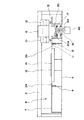
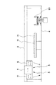
図1において、符号2は大型インクジェットプリンタのYレールであり、基台4に支持部材を介して架設されている。6は記録ヘッドを内蔵搭載したヘッド部であり、前記Yレール2に往復動可能に連結している。前記ヘッド部6には、複数個のインクジェット記録ヘッドが内蔵され、各記録ヘッドのインク吐出ノズルが前記ヘッド部6の底部の開口部に、同一面上に配列配置されている。前記ヘッド部6の、Y軸方向の両側には、UVランプ(紫外線ランプ)を備えた紫外線照射装置10,12が設けられている。14はプラテンであり、紙面垂直方向に延びる載置面に、プリント基板などの板状の印字媒体16を取り付けるためのバキューム機能を備えている。
【0007】
前記プラテン14は、基台4に、床面に対して水平に固設された、紙面垂直方向に延びるXレール(図示省略)上に、移動可能に支持されている。前記プラテン14及びヘッド部6は、それぞれコントローラによって制御されるXY駆動装置に連係している。図1はヘッド部6が、プラテン14上の印字領域から外れたホームポジション22即ちヘッド待機位置に移動した状態を示している。
【0008】
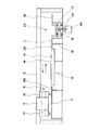
図1において、ヘッド待機位置22にいるヘッド部6の下方には、昇降機構18により昇降可能に支持された洗浄ボックス20が配置されている。前記洗浄ボックス20の底部の排出口にチューブ44が垂直に連結している。46は基台4に配置された廃液タンクであり、これの上蓋に形成された孔に前記チューブ44がスライド自在に嵌合している。7はヘッド移動方向変換位置8に、前記プラテン14に隣接して配置された板材であり、脚台9によって、プラテン14と同一高さに、基台4上に支持されている。前記板材7は、前記ヘッド部6がヘッド移動方向変換位置8に移動してきたとき、図2に示すように、紫外線照射装置10,12の下側に近接して位置するように配置されている。
【0009】
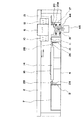
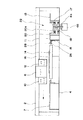
11,13は洗浄ボックス20の、Y軸方向の両側に配置された板材であり、脚台15,17によって、前記プラテン14と同一高さとなるように、基台4上に支持されている。前記板材11,13は、前記ヘッド部6がホームポジション22に移動してきたとき、紫外線照射装置10,12の下側に近接して位置するように配置されている。前記板材7,11,13の上面は、紫外線を吸収し、その反射量を減少させるために、黒色などの暗色となっている。24,26は照度計28を置くための載置板であり、プラテン14と同一の高さと、それより一段低い照度計載置位置との間で昇降可能に、前記脚台9,15に支持されている。
前記載置板24,26の上面は黒などの暗色に着色され、該上面は前記プラテン14のY軸方向の両側と板材7,11との間に配置されている。
【0010】
次に本実施形態の動作について説明する。
まず、プラテン14上にプリント基板などの板状の印字媒体16をセットする。印字動作がスタートすると、ヘッド部6は、コントローラの制御により、Yレール2に沿って、印字領域内で主走査方向に往復駆動される。一方、プラテン14は、Xレールに沿って副走査方向に駆動される。このとき、記録ヘッドから紫外線硬化型のインク滴が吐出され、プラテン14上の印字媒体16に印字が行われると共に、印字媒体16の印字直後の印字部のインク滴及び前の印字ラインに紫外線照射装置10,12のUVランプによって紫外線が照射され、印字直後のドットの硬化が行われる。ヘッド部6が、印字領域外のヘッド移動方向変換位置8に移動すると、紫外線照射装置10,12の照射口は板材7の上面に近接対向する。これにより、紫外線照射装置10,12の照射口から照射する紫外線は、板材7の上面に当たり、その一次反射光が照射口の近傍に当たる。そのため、紫外線の一次反射光が記録ヘッドのノズルに回り込むことがない。
【0011】
また、記録ヘッドから洗浄液を大量に吐出し、ヘッド部6に搭載されたサブタンク及び記録ヘッドのノズルを洗浄する場合、あるいは、サブタンクから記録ヘッドへインクを押し出し、記録ヘッドからインクを吐出して記録ヘッドのクリーニングを行う場合、また記録ヘッドがホームポジション側に戻ってくる場合、ヘッド部6は、Yレール2に沿ってホームポジションの、洗浄ボックス20の直上に向けて移動する。ヘッド部6が洗浄ボックス20の直上に移動すると、紫外線照射装置10,12の照射口は、板材11,13の上面に近接対向し、紫外線の一次反射光が記録ヘッドのノズルの内部に回り込むことがない。また、紫外線照射装置12が洗浄ボックス20の上方を通過するときも、紫外線照射装置12の照射口は、洗浄ボックス20の内部底面20aと近接対向することになり、この場合にも紫外線の一次反射光が記録ヘッドのノズルが開口する底面に回り込むことがない。
【0012】
尚、ヘッド部6が洗浄ボックス20の直上のヘッド待機位置22にあるとき、紫外線照射装置10,12の下側には板材11,13の上面が近接して位置するが、この紫外線照射装置10,12に近接する板材11,13の存在により、記録ヘッドのヘッド待機位置におけるメンテナンス作業のとき、作業者が高温状態にある紫外線照射装置10,12の下側に手を入れることができないようになっている。これにより、作業者が誤って紫外線照射装置10,12の下側に手を入れ、高温状態の照射口に接触する事故を防止している。装置のメンテナンス時、ヘッド部6が移動しているときの、紫外線の光量の計測を行う場合には、載置板24,26を一段下げ、その上にそれぞれ、図4に示すように、照度計28,28を載置し、計測を行う。このように、本実施形態では、ホームポジションでヘッド部6の下に手を入れて作業を行うときに安全であり、また、照度計28を用いて計測をするときに照度計28の置き場所に困らないという効果がある。
【0013】
【発明の効果】
本発明は上述の如く構成したので、紫外線照射装置から照射される紫外線の反射光がヘッド部内のインクに当たり、インクが固化してヘッド部内のインクの通路が詰まるのを防止することができる。
【図面の簡単な説明】
【図1】インクジェット記録装置の全体正面説明図である。
【図2】インクジェット記録装置の全体正面説明図である。
【図3】インクジェット記録装置の全体正面説明図である。
【図4】インクジェット記録装置の全体正面説明図である。
【図5】従来技術の説明図である。
【符号の説明】
2 Yレール
4 基台
6 ヘッド部
7 板材
8 ヘッド移動方向変換位置
9 脚台
10 紫外線照射装置
11 板材
12 紫外線照射装置
13 板材
14 プラテン
15 脚台
16 印字媒体
17 脚台
18 昇降機構
20 洗浄ボックス
22 ホームポジション
24 載置板
26 載置板
28 照度計
44 チューブ
46 廃液タンク[0001]
BACKGROUND OF THE INVENTION
The present invention relates to an ink jet recording apparatus having an ultraviolet irradiation device in a head portion on which a recording head is mounted.
[0002]
[Prior art]
In the case where printing is performed on the surface of a medium, such as a resin, into which ink does not permeate, an apparatus for irradiating UV (ultraviolet rays) has been proposed for the purpose of curing the surface after inkjet printing (see, for example, Patent Document 1).
There is also known an apparatus in which a UV curing lamp for curing ink immediately after printing is provided on the side of the head (for example, see Patent Document 2).
[0003]
[Patent Document 1]
Japanese Patent Laid-Open No. 10-16206 (first page, FIG. 1)
[Patent Document 2]
JP-A-60-132767 (first page, FIG. 1)
[0004]
[Problems to be solved by the invention]
In an apparatus using UV ink, in a normal use environment in a room, the apparatus may be covered with a cover, and the ink of the recording head with the nozzle facing downward is not often solidified. However, as shown in FIG. 5, in the apparatus in which the
The present invention aims to solve the above problems.
[0005]
[Means for Solving the Problems]
In order to achieve the above object, the present invention relates to a home position in which a head unit having an ultraviolet irradiation device for irradiating ultraviolet rays to ink droplets immediately after printing is removed from the printing area on the platen, and the home position. In the ink jet recording apparatus that is movable to the opposite head movement direction conversion position, the area of the home position and the head movement direction conversion position is close to the lower side of the irradiation port of the ultraviolet irradiation apparatus in the area. As described above, a plate material for preventing the reflection of ultraviolet rays to the recording head is provided.
In the present invention, the height of the plate is set to be substantially the same as the height of the platen.
Moreover, this invention makes the surface which opposes the irradiation port of the said ultraviolet irradiation device of the said board | plate material dark color, such as black.
According to the present invention, a mounting plate is provided so as to be movable up and down in the movement path of the ultraviolet irradiation device adjacent to the plate material, and an illuminometer can be placed on the mounting plate.
[0006]
DETAILED DESCRIPTION OF THE INVENTION
Hereinafter, the configuration of the present invention will be described in detail with reference to the accompanying drawings.
In FIG. 1,
[0007]
The
[0008]
In FIG. 1, a
[0009]
The upper surfaces of the
[0010]
Next, the operation of this embodiment will be described.
First, a plate-
[0011]
Also, when a large amount of cleaning liquid is discharged from the recording head to clean the sub tank and the nozzle of the recording head mounted on the
[0012]
When the
[0013]
【The invention's effect】
Since the present invention is configured as described above, it is possible to prevent the reflected light of the ultraviolet rays irradiated from the ultraviolet irradiation device from hitting the ink in the head portion and solidifying the ink and clogging the ink passage in the head portion.
[Brief description of the drawings]
FIG. 1 is an overall front view of an ink jet recording apparatus.
FIG. 2 is an overall front explanatory view of the ink jet recording apparatus.
FIG. 3 is an overall front view of the ink jet recording apparatus.
FIG. 4 is an overall front explanatory view of the ink jet recording apparatus.
FIG. 5 is an explanatory diagram of a prior art.
[Explanation of symbols]
2
Claims (4)
Priority Applications (1)
| Application Number | Priority Date | Filing Date | Title |
|---|---|---|---|
| JP2003138612A JP4557504B2 (en) | 2003-05-16 | 2003-05-16 | Inkjet recording device |
Applications Claiming Priority (1)
| Application Number | Priority Date | Filing Date | Title |
|---|---|---|---|
| JP2003138612A JP4557504B2 (en) | 2003-05-16 | 2003-05-16 | Inkjet recording device |
Publications (2)
| Publication Number | Publication Date |
|---|---|
| JP2004338264A JP2004338264A (en) | 2004-12-02 |
| JP4557504B2 true JP4557504B2 (en) | 2010-10-06 |
Family
ID=33527932
Family Applications (1)
| Application Number | Title | Priority Date | Filing Date |
|---|---|---|---|
| JP2003138612A Expired - Fee Related JP4557504B2 (en) | 2003-05-16 | 2003-05-16 | Inkjet recording device |
Country Status (1)
| Country | Link |
|---|---|
| JP (1) | JP4557504B2 (en) |
Families Citing this family (7)
| Publication number | Priority date | Publication date | Assignee | Title |
|---|---|---|---|---|
| JP4770837B2 (en) | 2005-10-14 | 2011-09-14 | コニカミノルタエムジー株式会社 | Inkjet recording apparatus and inkjet recording method |
| JP2007118414A (en) | 2005-10-28 | 2007-05-17 | Konica Minolta Medical & Graphic Inc | Inkjet recording device |
| JP5078383B2 (en) | 2007-02-19 | 2012-11-21 | 株式会社セイコーアイ・インフォテック | Inkjet recording device |
| JP5262494B2 (en) * | 2008-09-17 | 2013-08-14 | セイコーエプソン株式会社 | Fluid ejection device |
| JP5144615B2 (en) * | 2009-09-14 | 2013-02-13 | 株式会社セイコーアイ・インフォテック | Inkjet recording device |
| JP6497026B2 (en) * | 2014-10-22 | 2019-04-10 | セイコーエプソン株式会社 | Liquid ejector |
| JP7343322B2 (en) | 2019-07-25 | 2023-09-12 | ローランドディー.ジー.株式会社 | inkjet printer |
Family Cites Families (3)
| Publication number | Priority date | Publication date | Assignee | Title |
|---|---|---|---|---|
| JP2002292887A (en) * | 2001-03-30 | 2002-10-09 | Brother Ind Ltd | Ink jet recording device |
| JP2003011334A (en) * | 2001-06-29 | 2003-01-15 | Canon Inc | Ink jet recording apparatus and ink jet recording method |
| JP4292790B2 (en) * | 2002-11-22 | 2009-07-08 | コニカミノルタホールディングス株式会社 | Inkjet printer |
-
2003
- 2003-05-16 JP JP2003138612A patent/JP4557504B2/en not_active Expired - Fee Related
Also Published As
| Publication number | Publication date |
|---|---|
| JP2004338264A (en) | 2004-12-02 |
Similar Documents
| Publication | Publication Date | Title |
|---|---|---|
| JP2009226692A (en) | Inkjet printer | |
| JP4557504B2 (en) | Inkjet recording device | |
| WO2014069494A1 (en) | Inkjet printing device | |
| CN110733263B (en) | Nozzle protection mechanism and nozzle protection method for ink-jet printer | |
| US9022519B2 (en) | Printing device | |
| JP3855724B2 (en) | Inkjet printer and control method thereof | |
| CN110733264B (en) | Nozzle protecting device and nozzle protecting method for ink-jet printer | |
| JP2006110974A (en) | Inkjet printer | |
| JP4142345B2 (en) | Inkjet recording device | |
| JP2007118414A (en) | Inkjet recording device | |
| KR101124211B1 (en) | Inkjet printer equipped with nozzle-relieve-device and Method for relieving blockage of nozzle using the same | |
| US7396103B2 (en) | Inkjet recording apparatus and method for maintenance of recording head | |
| JP2011073271A (en) | Ink jet recorder and ink jet recording method using ink jet recorder | |
| JP4565880B2 (en) | Inkjet printer | |
| JP2003200564A (en) | Ink jet printer | |
| JP2004338263A (en) | Inkjet recording device | |
| JP2006068937A (en) | Inkjet printer | |
| JP3127748U (en) | Inkjet device for large inkjet printer | |
| JP2004001328A (en) | Inkjet recording device | |
| JP4622451B2 (en) | Inkjet recording device | |
| US20050190224A1 (en) | Image recording apparatus | |
| CN103895351B (en) | page width printing device | |
| CN211994708U (en) | Full-automatic UV industry shower nozzle device of moisturizing | |
| JP2004322461A (en) | Image recording device | |
| JP2021014054A (en) | Ink jet printer |
Legal Events
| Date | Code | Title | Description |
|---|---|---|---|
| A621 | Written request for application examination |
Free format text: JAPANESE INTERMEDIATE CODE: A621 Effective date: 20060510 |
|
| A711 | Notification of change in applicant |
Free format text: JAPANESE INTERMEDIATE CODE: A712 Effective date: 20070822 |
|
| A977 | Report on retrieval |
Free format text: JAPANESE INTERMEDIATE CODE: A971007 Effective date: 20090415 |
|
| A131 | Notification of reasons for refusal |
Free format text: JAPANESE INTERMEDIATE CODE: A131 Effective date: 20090420 |
|
| A521 | Request for written amendment filed |
Free format text: JAPANESE INTERMEDIATE CODE: A523 Effective date: 20090527 |
|
| A131 | Notification of reasons for refusal |
Free format text: JAPANESE INTERMEDIATE CODE: A131 Effective date: 20091203 |
|
| A521 | Request for written amendment filed |
Free format text: JAPANESE INTERMEDIATE CODE: A523 Effective date: 20100112 |
|
| TRDD | Decision of grant or rejection written | ||
| A01 | Written decision to grant a patent or to grant a registration (utility model) |
Free format text: JAPANESE INTERMEDIATE CODE: A01 Effective date: 20100706 |
|
| A01 | Written decision to grant a patent or to grant a registration (utility model) |
Free format text: JAPANESE INTERMEDIATE CODE: A01 |
|
| A61 | First payment of annual fees (during grant procedure) |
Free format text: JAPANESE INTERMEDIATE CODE: A61 Effective date: 20100720 |
|
| R150 | Certificate of patent or registration of utility model |
Ref document number: 4557504 Country of ref document: JP Free format text: JAPANESE INTERMEDIATE CODE: R150 Free format text: JAPANESE INTERMEDIATE CODE: R150 |
|
| FPAY | Renewal fee payment (event date is renewal date of database) |
Free format text: PAYMENT UNTIL: 20130730 Year of fee payment: 3 |
|
| FPAY | Renewal fee payment (event date is renewal date of database) |
Free format text: PAYMENT UNTIL: 20130730 Year of fee payment: 3 |
|
| S531 | Written request for registration of change of domicile |
Free format text: JAPANESE INTERMEDIATE CODE: R313531 |
|
| FPAY | Renewal fee payment (event date is renewal date of database) |
Free format text: PAYMENT UNTIL: 20130730 Year of fee payment: 3 |
|
| R350 | Written notification of registration of transfer |
Free format text: JAPANESE INTERMEDIATE CODE: R350 |
|
| R250 | Receipt of annual fees |
Free format text: JAPANESE INTERMEDIATE CODE: R250 |
|
| R250 | Receipt of annual fees |
Free format text: JAPANESE INTERMEDIATE CODE: R250 |
|
| LAPS | Cancellation because of no payment of annual fees |