JP4555411B2 - Hydroformylation process - Google Patents
Hydroformylation process Download PDFInfo
- Publication number
- JP4555411B2 JP4555411B2 JP34176398A JP34176398A JP4555411B2 JP 4555411 B2 JP4555411 B2 JP 4555411B2 JP 34176398 A JP34176398 A JP 34176398A JP 34176398 A JP34176398 A JP 34176398A JP 4555411 B2 JP4555411 B2 JP 4555411B2
- Authority
- JP
- Japan
- Prior art keywords
- hydroformylation
- solvent
- catalyst
- product
- zone
- Prior art date
- Legal status (The legal status is an assumption and is not a legal conclusion. Google has not performed a legal analysis and makes no representation as to the accuracy of the status listed.)
- Expired - Fee Related
Links
Images


Classifications
-
- C—CHEMISTRY; METALLURGY
- C07—ORGANIC CHEMISTRY
- C07C—ACYCLIC OR CARBOCYCLIC COMPOUNDS
- C07C45/00—Preparation of compounds having >C = O groups bound only to carbon or hydrogen atoms; Preparation of chelates of such compounds
- C07C45/49—Preparation of compounds having >C = O groups bound only to carbon or hydrogen atoms; Preparation of chelates of such compounds by reaction with carbon monoxide
- C07C45/50—Preparation of compounds having >C = O groups bound only to carbon or hydrogen atoms; Preparation of chelates of such compounds by reaction with carbon monoxide by oxo-reactions
-
- C—CHEMISTRY; METALLURGY
- C07—ORGANIC CHEMISTRY
- C07C—ACYCLIC OR CARBOCYCLIC COMPOUNDS
- C07C29/00—Preparation of compounds having hydroxy or O-metal groups bound to a carbon atom not belonging to a six-membered aromatic ring
- C07C29/16—Preparation of compounds having hydroxy or O-metal groups bound to a carbon atom not belonging to a six-membered aromatic ring by oxo-reaction combined with reduction
Landscapes
- Chemical & Material Sciences (AREA)
- Organic Chemistry (AREA)
- Chemical Kinetics & Catalysis (AREA)
- Organic Low-Molecular-Weight Compounds And Preparation Thereof (AREA)
- Low-Molecular Organic Synthesis Reactions Using Catalysts (AREA)
Description
【0001】
【発明の属する技術分野】
本発明は、溶媒ならびに8、9または10族金属(1997年使用のIUPAC元素分類参照)に基づく均一触媒の存在下に反応ゾーンで、エチレン性不飽和化合物を一酸化炭素・水素ガスと接触させるヒドロホルミル化方法に関するものである。
【0002】
【従来の技術】
エチレン性不飽和化合物のヒドロホルミル化によるアルデヒドおよび/またはアルコールなどの生成物の形成は、工業的にかなり重要なものである。文献から明らかなように(例えば、“New Syntheses with Carbon Monoxide”, J.Falbe, Springer-Verlag (1980); ISBN 0-387-09674-4および“Carbonylation”, H.M.Colqhoun, D.J.Thompson and M.V.Twigg, Plenum Press, 1991; ISBN 0-306-43747-3)、8族、9族または10族金属(Fe、Ru、Os;Co、Rh、Ir;Ni、PdおよびPt)に基づく複数の触媒がヒドロホルミル化方法で用いられている。現在最も重要な工業的ヒドロホルミル化方法は、9族金属CoおよびRhに基づいたものである。10族金属Ni、PdおよびPtに基づいたヒドロホルミル化方法についても、広範囲の特許技術がある。
【0003】
【発明が解決しようとする課題】
決して失われる触媒の交換のコストのためではなく、各種の理由のために、ヒドロホルミル化生成物から触媒を回収しなければならない。しかしながら、ヒドロホルミル化生成物の単なる蒸留は触媒を失活させ、従って破壊する可能性がある。従って、破壊する傾向のある触媒は、例えば抽出によって分離する。
【0004】
国際出願WO 95/05354には、反応終了後に粗生成物を混和しない2層とし、ヒドロホルミル化生成物を含む層を触媒を含む層から分離することで、触媒系の金属成分の大部分を回収する方法が開示されている。しかしながら、生成物層にはなお、活性な触媒が含まれている。その引例には、その触媒をどのようにして回収すべきかについての記載はない。
【0005】
EP−A−0350922からは、非水系ヒドロホルミル化反応生成物組成物からアルデヒド生成物を分離・回収する方法が公知である。その方法では、水を加えるかあるいは水と非極性炭化水素系化合物の両方を加えることによる相分離が関与する。その引例の比較例1には、単なる相分離による回収が不十分であることが示されているが、水を加えると相分離が改善されることが示されている。
しかしながら、その方法を水溶性ヒドロホルミル化触媒系の存在下に実施する場合を観察すべきである。そこで、金属錯体とともに、相分離段階で容易に分かれて水相に入るイオン的に帯電したリン配位子を用いる。比較的一般的な種類の配位子である非イオン帯電リン配位子に基づいた触媒系の場合については、当該明細書にも記載はない。
【0006】
本発明者らは、非イオン帯電配位子に基づく、触媒がほぼ完全に回収されるヒドロホルミル化方法を開発すべく尽力した。
【0007】
【課題を解決するための手段】
従って、
(a)溶媒および8、9または10族金属に基づく均一触媒ならびに非イオン帯電配位子の存在下に、反応ゾーンで、一酸化炭素・水素ガスと1以上のエチレン性不飽和化合物を接触させて、粗反応生成物を形成させる段階;
(b)大部分の触媒が溶解している溶媒の大部分を分離させ、相分離ゾーンで粗ヒドロホルミル化生成物から回収する段階;ならびに
(c)抽出ゾーンで、非水系抽出剤を用いて、実質的に全ての溶解残留触媒を、段階(b)から得られた分離ヒドロホルミル化生成物から除去する段階
を有することを特徴とするヒドロホルミル化方法が提供される。
【0008】
段階(c)では、抽出剤として、好ましくは段階(a)で使用した溶媒と同じ物質を用いることで、循環流の汚染を回避する。
【0009】
循環流を用いる(完全統合型の)方法では、抽出段階(c)は好ましくは、段階(c)で得られるヒドロホルミル化生成物中に溶解している溶媒の量に一致する量の抽出剤で(他段階にて)行う。分離段階(b)後では、ヒドロホルミル化生成物はなお、溶媒で飽和していることは留意すべき点である。例えば40℃の温度では、スルホラン飽和粗C11〜C12オレフィン由来ヒドロホルミル化生成物100gには、スルホランが約8g含有されていることから、スルホラン約8gを用いて抽出を行うべきである。明らかに、抽出剤の量は正確に一致している必要はない。その方法は、例えば0.9〜1.1倍の量で処理するよう調整することができる。
【0010】
抽出段階(c)によって、触媒を含んだ抽出剤が得られる。段階(c)からの抽出剤と溶媒が同一の物質である場合は、触媒含有抽出剤を段階(a)の反応ゾーンおよび/または段階(b)の分離ゾーンに送ることができる。本発明者らは、段階(b)で分離効率の大幅向上が得られたことから、後者の実施態様が有効であることを認めている。
【0011】
段階(c)から得られる溶媒抽出ヒドロホルミル化生成物には、溶媒および/または抽出剤が含まれている。その溶媒および/または抽出剤も除去する必要があるのが普通である。この時点で抽出されたヒドロホルミル化生成物は貴重な触媒を含まないことから、蒸留が一つの選択肢である。しかしながら、その分離方法は、溶媒、抽出剤および生成物が類似した沸点を有する場合には適用可能性が低いものになると考えられる。従って、洗浄による除去が好ましい。
【0012】
【発明の実施の形態】
明らかに、溶媒および/または抽出剤を洗浄によって除去する場合には、洗浄に使用する媒体の存在によって、問題が大きくなってはならない。すなわち、ヒドロホルミル化生成物の該媒体への溶解度は、前記溶媒および/または抽出剤への溶解度より低いものでなければならない。さらに、洗浄媒体は好ましくは、循環流の一部になった場合に、望ましくない副作用を起こさない無害の不純物でなければならない。さらに、該媒体は安価でなければならない。
【0013】
水は洗浄媒体として非常に有効であることが認められた。そこで好ましくは、(d)段階(c)から得られた抽出ヒドロホルミル化生成物から、洗浄ゾーンにて、洗浄媒体(好ましくは水)を用いて、実質的に全ての溶解している残留溶媒および/または残留抽出剤を除去し、洗浄ゾーンから得られる洗浄媒体から溶媒および/または抽出剤を分離し、適宜にそれぞれを再使用するという段階(d)を加える。
【0014】
好ましくは、水洗は60℃を超える温度、より好ましくは70℃を超える温度で、粗生成物と媒体の相比が重量基準で1:0.2〜1:1となるように行う(多段階にて)。乳濁を回避するには、その低い方の温度が重要である。
【0015】
抽出剤と溶媒が同じ物質である好ましい実施態様においては、単離された抽出剤を段階(c)での抽出剤として再使用することが好ましい。驚くべきことに、その少量の抽出剤が、段階(b)で得られる分離ヒドロホルミル化生成物から実質的に全ての残留触媒を効果的に除去するのに十分である。
【0016】
抽出は、回転円板式接触反応器(PerryのChemical Engineers' Handbook, 6th ed., p.21-77およびそれ以降参照)または充填床カラムで実施することができる。本発明の方法では、充填床カラムの方が有効であり、望ましくない乳濁が回避されることから好ましい。最も高い抽出効率が得られるのは、充填床カラムを用い、構造化充填を行った場合である。
【0017】
段階(b)から得られる分離された溶媒は貴重な触媒を含むことから、好ましくは、当該方法の段階(a)の反応ゾーンに送る。
【0018】
好ましくは、段階(b)の相分離は、(単相の)ヒドロホルミル化生成物を0〜80℃の範囲、好ましくは15〜60℃の範囲の温度まで冷却することで生じる。しかしながら、各場合について、冷却の程度および相分離を起こすのに必要な溶媒の最適量を決めることは当業者の裁量の範囲内である。圧力については具体的な必要条件はない。以下に示す実験結果は、使用が好ましい溶媒の量を示しているものでもある。
【0019】
本発明の方法のさらに別の実施態様は、相分離の問題に関係するものである。それらの問題は、層分離を明瞭に行う上で過度に長時間を要すること、ならびに室温での相分離の場合に室温より低い温度の冷媒を用いる必要があることに関するものである。前者の問題は、細かい乳濁液が形成されるためであると思われ、後者の問題は、温度と両層での触媒分布との間の関係によるものであると思われる。上記の第2の問題は、生成物層に溶解している触媒が抽出によって回収されることから、本発明の方法によって既に部分的に解決されていることは留意すべき点である。
【0020】
本発明者らは、上記方法の段階(b)で遠心機、濾床コアレッサもしくは静電コアレッサを用いることで、貴重な材料を損失することなく、非常に適切な形で乳濁が破壊されることを見出した。他方、開放沈降機、平行板沈降機および水力サイクロンなどの従来の装置を使用すると、良好な結果が得られないことがわかっている(乳濁液を破壊する装置に関する定義については、“Perry's Chemical Engineers' Handbook”, 6 th ed., pp.21-64; 21-65 and 21-66参照)。
【0021】
EP−A−0350922号にあるように、相分離の前に、粗ヒドロホルミル化生成物に液体飽和炭化水素類を加えることが有効であることが認められている。好ましくは、その炭化水素は、ライトエンド以下の沸点を有するものである(すなわち、その工程で生じるパラフィン系副産物)。実際には、ライトエンド自体を用いることができる。それによって、比較的高温であっても相分離を促進する効果などが得られる。それによって、温度がさほど低くない、従って比較的安価な冷媒を使用することができる。さらに別の利点としては、抽出の向上(飽和炭化水素中では触媒の溶解度は小さいのが普通であることから)、および抽出されたヒドロホルミル化生成物の洗浄の向上がある。好適には、炭化水素の使用量は、生成物流基準で10〜50%である。
【0022】
上記のような主要工程に加えて、ヒドロホルミル化生成物の一部を反応ゾーンに循環させて、溶媒中のエチレン性不飽和化合物の溶解を促進することが有利であることが認められた。それは特に、運転開始時に有利である。好適には、20%以下のヒドロホルミル化生成物を循環させることができる。
【0023】
原料として使用されるエチレン性不飽和化合物は、1個の二重結合を有する化合物であることができる。それは、骨格鎖に結合した官能基を有することができるか、あるいは骨格鎖内に炭素以外の原子を有することができる。好ましくは、1分子当たり2〜30個の炭素原子を有するものとする。それら化合物は、そのようなエチレン性不飽和化合物の混合物として使用することもできる。より好ましくは、エチレン性不飽和化合物は、1分子当たり4〜24個の炭素原子を有するオレフィンであるか、あるいはそのようなオレフィン類の混合物である。1分子当たり2個または3個のみの炭素原子を有するオレフィンを用いた場合、段階(b)での相分離を起こさせることが困難な場合がある。最も好ましくは、炭素数6〜18のオレフィンまたはそれの混合物である。そのようなオレフィン混合物は市販されていて容易に入手でき、それらの生成物は、貴重な洗剤および可塑剤中間体を提供するものである。
【0024】
一酸化炭素・水素ガスは、等モル比または非等モル比、例えば5:1〜1:5の範囲内の比率で供給することができる。好ましくはそのガスは、2:1〜1:2.5の範囲内の比率で供給する。
【0025】
ヒドロホルミル化は、中等度の反応条件で好適に実施することができる。従って、50〜200℃の範囲の温度が望ましく、好ましい温度は70〜160℃の範囲である。絶対圧1〜300バールの範囲の反応圧力が好適であるが、絶対圧5〜100バールの範囲が好ましい。それより低いまたは高い圧力を選択することができるが、あまり有利とは思われない。
【0026】
ヒドロホルミル化生成物からほとんどの全ての触媒系を選択的に溶解させることができる好適な溶媒は、分子内において非プロトン性の極性基が存在することを特徴とするものである。不飽和原料が比較的低い分子量を有する場合、例えば、炭素数5〜7のエチレン性不飽和化合物を用いる場合、強力な極性基を有する溶媒が特に好ましい。比較的高い分子量の不飽和化合物、例えば炭素数12〜16のオレフィンのヒドロホルミル化の場合、極性の相対的に低い溶媒を用いることで、満足できる結果が得られるのが普通である。
【0027】
スルホンを含む溶媒または実質的にスルホンからなる溶媒が好ましい。特に好ましい溶媒には、ジメチルスルホンおよびジエチルスルホンなどのジアルキルスルホン類、ならびにスルホラン(テトラヒドロチオフェン−2,2−ジオキサイド)、2−メチルスルホランおよび2−メチル−4−エチルスルホランなどの環状スルホンなどがある。さらに別の種類の好適な溶媒には、マロノニトリル、スクシノニトリル、アジポニトリル、ジヒドロムコニトリル、ピメロニトリル、スベロニトリル、1,6−ジシアノシクロヘキサン、1,2,4−トリシアノブタンなどの2以上のシアノ基を有する種類の化合物、ならびにそれらの混合物でスルホランを含むものまたは含まないものなどがある。
【0028】
他の混合溶媒も使用することができ、それには例えば、スルホンおよび/または2以上のシアノ基を有する化合物とアルコールなどのプロトン性溶媒との混合物などがある。オレフィンのヒドロホルミル化では、ヒドロホルミル化反応で生じるアルコールと同一または類似のアルコールを選択するのが普通である。スルホランが、本方法では好ましい溶媒である。
【0029】
抽出剤はさらに、分子内に非プロトン性極性基を有することを特徴とするものでもある。従って、上記の化合物(溶媒としての)が好適な抽出剤である。好ましい実施態様においては、抽出剤および溶媒は同一のものとする。
【0030】
本発明の方法で使用される溶媒の量は、かなり変動し得るものである。例えば、溶媒量は、溶媒、エチレン性不飽和化合物および触媒を含む反応混合物の体積の3〜50体積%で変動し得る。
【0031】
本明細書では、触媒は、非修飾の8族、9族もしくは10族金属カルボニルならびに8族、9族もしくは10族金属水素化カルボニルとすることができるが、より好ましくは触媒は、1以上の非カルボニル配位子で修飾されたものとする。ヒドロホルミル化生成物の製造ですでに使用されている非カルボニル配位子の例としては、ホスフィン類、ホスフィンオキサイド類、亜リン酸化合物などがある。本発明は、修飾された8族、9族もしくは10族金属に基づく触媒、特にはCo、Rh、Ni、PdもしくはPtに基づく触媒を用いた場合に特に有用である。本発明は、EP−A−0220767、US−A−3527818、EP−A−0495547に記載のいずれかの触媒を用いる場合、及び特にはWO 95/05354の触媒を用いる場合に特に有用である(これらはいずれも、引用によって本明細書に含まれるものとする)。
【0032】
好適な触媒系は例えば、以下のものを含有する:
(i)10族金属カチオン源;
(ii)ハライドアニオン以外のアニオン源、例えば18℃の水溶液で測定した場合のpKa値が3未満である酸から誘導したもの;及び
(iii)一般式:
R1R2P−R−PR3R4 (I)
で示される二座配位子源[上記式中、Rは架橋部に1〜10個の原子を有する二価の架橋基であり、R1、R2、R3およびR4は独立に、置換もしくは未置換の脂肪族基を表すか、あるいはR1とR2および/またはR3とR4とが一体となって、5以上の環原子を有する二価の基を表すことで、2個の遊離原子価がリン原子に結合している]。
【0033】
好適な金属源の例としては、酢酸パラジウム(II)およびアセチルアセトン酸白金(II)である。
【0034】
ハライドアニオン以外のアニオン源としては、アニオンを発生するいかなる化合物も使用することができる。そのような化合物には、酸またはそれの塩などがあり、例えば、上記の酸のいずれかがあり、それらはまた8族、9族もしくは10族金属の塩にも含まれ得るものである。アニオンは好ましくは、強酸、すなわち18℃の水溶液で測定した場合のpKa値が3未満、好ましくは2未満の酸から誘導されるものである。それらの酸から誘導されるアニオンは、金属に配位しないか、弱く配位するものである。酸が強いほど、金属カチオンへのアニオンの配位は弱くなり、ヒドロホルミル化生成物の直線性が高くなる。
【0035】
好適なアニオンの代表例は、リン酸、硫酸、スルホン酸ならびにトリフルオロ酢酸などのハロゲン化カルボン酸のアニオンである。さらに、錯アニオンも好適であり、それには例えば、BF3、B(C6F5)3、AlCl3、SnF2、Sn(CF3SO3)2、SnCl2もしくはGeCl2などのルイス酸と、CF3SO3HもしくはCH3SO3Hなどのスルホン酸などのプロトン酸またはHFもしくはHClなどのハロゲン化水素酸との組み合わせ、あるいはルイス酸とアルコールとの組み合わせによって発生するアニオン等がある。そのような錯アニオンの例としては、BF4 −、SnCl3 −、[SnCl2・CF3SO3]−およびPF6 −がある。好ましいアニオン源は、トリフルオロメタンスルホン酸である。
【0036】
Rで表されるジホスフィンにおける架橋基は代表的には、炭素原子から成るものである。好ましくは、該架橋基には、架橋部に2もしくは3個の炭素原子がある。
【0037】
式(I)の配位子では、R1、R2、R3およびR4は独立に、炭素数1〜4のアルコキシ基、ハロゲン原子または(C1〜C4アルキル)アミノ基などの置換基で置換されていても良い各種の非環状基もしくは環状基を表すことができる。その例としては、エチル基、イソプロピル基、sec−ブチル基およびtert−ブチル基などのアルキル基;シクロペンチル基およびシクロヘキシル基などのシクロアルキル基;フェニル基およびトリル基などのアリール基がある。
【0038】
しかしながら好ましくは、R1とR2あるいはR3とR4の一方または両方が一体となって、二価の(置換された)基を表すものとする。
【0039】
二価の(置換された)基は好ましくは、6〜9個の環原子を有し、より好ましくは8個の環原子を有する環状基である。置換基がある場合それは、炭素数1〜4のアルキル基であるのが普通である。原則として、全ての環原子が炭素原子であるが、環中に酸素原子もしくは窒素原子などの1個もしくは2個のヘテロ原子を有する二価の環状基も除外されない。好適な二価環状基の例としては、1,4−シクロヘキシレン基、1,4−シクロへプチレン基、1,4−シクロオクチレン基、1,5−シクロオクチレン基、2−メチル−1,5−シクロオクチレン基、2,6−ジメチル−1,4−シクロオクチレン基および2,6−ジメチル−1,5−シクロオクチレン基がある。
【0040】
好ましい二価環状基は、1,4−シクロオクチレン、1,5−シクロオクチレンおよびそれらのメチル(ジ)置換誘導体から選択される。
【0041】
異なる二価環状基を有する配位子の混合物も使用することができ、その例としては1,4−シクロオクチレン基を有する配位子および1,5−シクロオクチレン基を有する配位子の混合物などがある。従って、好ましい式(I)の二座配位子は、1,2−ビス(1,4−シクロオクチレンホスフィノ)エタン、1,2−ビス(1,5−シクロオクチレンホスフィノ)エタンおよびそれらの混合物ならびに1,3−ビス(1,4−シクロオクチレンホスフィノ)プロパン、1,3−ビス(1,5−シクロオクチレンホスフィノ)プロパンおよびそれらの混合物である。
【0042】
二座配位子の製造については、例えばGB−A−1127965に開示の方法のような公知の方法を参照する。
【0043】
触媒系の使用量は重要ではなく、広範囲で変動することができる。通常、エチレン性不飽和化合物1モル当たり10−8〜10−1、好ましくは10−7〜10−2モル金属原子の範囲の量を用いる。触媒系に含まれる各物質の量は、金属1モル原子当たりで、二座配位子を0.5〜10モル、好ましくは1〜6モルを用い、アニオン源もしくは錯アニオン源を0.5〜15モル、好ましくは1〜8モル用いるように適宜に選択する。
【0044】
本発明の方法の好ましい特徴は、ハライドアニオン(Clアニオン、BrアニオンまたはIアニオン)源を含む助触媒の存在にある。ただし、ハライドアニオンと金属カチオンとの間のモル比は多くとも5:1でなければならない。好ましくは、ハライドアニオンと金属カチオンの間のモル比は、多くとも1:1、例えば0.02:1〜1:1である。
【0045】
ハライドアニオン源として、上記反応条件下でハライドアニオンを発生させるいかなる化合物も使用することができる。
【0046】
望ましいものとしては、HCl、HBrおよびHIなどのハロゲン化水素およびNaCl、MgBr2、ZnCl2、ZnI2、KBr、RbCl、CsCl、CsI、MgI2およびCuClなどのハロゲン化金属などの無機化合物がある。塩素アニオン源を含む助触媒が特に好ましい。
【0047】
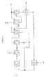
本発明の方法の各種実施態様を、添付の模式的ブロック図(図1、2および3)に示してある。
【0048】
これらの図において、記号は以下のものを表す:
1:一酸化炭素・水素ガス(合成ガス)
2:エチレン性不飽和化合物
3:触媒成分
4:溶媒
5:水
6:粗アルコール
7:ライトエンド
8:ヘビーエンド
9:最終品アルコール
10:水素ガス
11:1以上の気/液反応槽
12:1以上の気/液分離器
13:遠心器、コアレッサまたは沈降機
14:溶媒抽出カラム(触媒除去)
15:水抽出カラム(溶媒除去)
16:水/溶媒蒸留カラム
17:中間溶媒貯蔵槽
18:触媒調製
19:トッピング蒸留カラム(ライトエンド)
20:テーリング蒸留カラム(ヘビーエンド)
21:水素化仕上げ。
【0049】
図1では、ユニット(18)で調製した触媒の入った反応槽(11)に、エチレン性不飽和化合物(2)、一酸化炭素・水素ガス(1)を導入する。生成物を1以上の気/液分離器(12)に通す。その後生成物を、遠心器、濾床コアレッサもしくは静電コアレッサ(13)のいずれかに送る。溶媒層を、触媒とともに反応槽(11)に循環させる。生成物層を溶媒抽出カラム(14)に送り、そこで残留している触媒を除去する。負荷溶媒を、導管AまたはBを通過させて、(11)および/または(13)に送る。生成物を水抽出カラム(15)に送り、そこで溶媒が除去される。水層を蒸留カラム(16)に通して、頂部から水(5)を回収し、それを(15)に循環させ、溶媒(4)を(16)の底部から回収して、それを貯蔵槽(17)に循環させる。水および溶媒を循環させるための導管には、水(5)用導入口と溶媒(4)用導入口とがある。(15)から回収された生成物層(6)は、例えば図3に開示したような好適な後処理手順に送ることができる。
【0050】
図2は、好ましい実施態様を表したものであり、負荷溶媒が導管Bを通って(13)に送られる。さらにこの図には、粗反応生成物の一部を(11)に循環させる工程が描いてある。
【0051】
最後に図3には、好適な後処理手順が示してあり、そこでは生成物(6)が、さらに残留する水分を除去する1以上のライトエンド蒸留カラム(9)、1以上のヘビーエンド蒸留カラム(10)および最後に水素化仕上げ反応槽(11)に送られる。蒸留カラムの前に設けるケン化ユニット(不図示)は適宜設置するものである。さらに、水からの分離後に(不図示)、ライトエンド(7)および/またはヘビーエンド(8)を、反応槽(11)に循環させることができる。それは、飽和炭化水素を加えて相分離段階を行いやすくする場合に、特に有利である。
【0052】
以下の実施例によって、本発明をさらに説明する。これらの実施例では、以下の略称を用いる。
【0053】
BCPE=1,2−ビス(シクロオクチレンホスフィノ)エタン、
TFSA=トリフルオロメタンスルホン酸、
NaCl=塩化ナトリウム。
【0054】
【実施例】
参考例A
300mLのバッチ式オートクレーブ中で、ヒドロホルミル化を行った。アルゴン雰囲気下に、C11〜C12内部直鎖オレフィン62mL、水0.63mLおよびn−トリデカン0.755g(GC内部標準として)をオートクレーブに充填した。別個に、アルゴン雰囲気下で、無水スルホラン99.0g(40℃で攪拌したもの)に、酢酸Pd0.525g、BCPE1.01g、塩化亜鉛0.522gおよびTFSA0.92gを加えて、Pd濃度を約400ppmwとし、モル触媒比(Pd/BCPE/TFSA/塩化物)を1:1.4:2.6:3.2とすることで、触媒の調製を行った。その触媒ストックの1/6(16.96g)を、上記のバッチ式オートクレーブに加えた。その後、2−エチルヘキサノールも加えた。オートクレーブを閉じ、減圧および合成ガスによる加圧のサイクルを3回行うことで残留空気を除去した。中空軸攪拌機を用いて、攪拌速度を1000rpmとした。次に、圧力を56バール合成ガス(H2/COのモル比2.0)に設定し、急速に昇温して90℃とした。反応開始時には温度は105℃まで上昇し、圧力は降下した。その温度および50バールの圧力にて反応を維持した(恒圧バルブによる合成ガス補給を用いて)。105℃で3時間後、反応槽内容物を冷却して室温とした。GC分析は、3時間後のオレフィン変換率が>99.9%であり、アルコール、パラフィンおよびヘビーエンドに対する選択性がそれぞれ、99.0%、0.5%および0.5%であることを示していた(アルデヒドは認められなかった)。
【0055】
参考例B
参考例Aの生成物の一部を加熱して40℃とした(冷却用軟水を用いる、市販ユニットでの相分離には妥当なモデル温度)。この温度では、2つの液相が存在していた。上層は粗アルコールのほとんど白色の層であり、下層はスルホランに溶解したPd触媒の層(Pd触媒が存在するために黄色)である。これらの層を分離し、サンプリングし、n−ブタノールで希釈し、元素分析によって分析を行った。データは以下の表の通りである。
【0056】
【表1】

【0057】
参考例C
参考例Aで記載の実験を、2−エチルヘキサノールに代えて40:60(重量基準)C12/C13洗剤アルコール("DOBANOL" 23、商品名、直線性約80%)を用いて繰り返した。モル触媒比(Pd/BCPE/TFSA/Cl)は1:1.4:2.0:3.2とした。2時間後および4時間後のオレフィン変換率はそれぞれ、94.6%および>99.9%であった。4時間後の選択性はアルコール99.5%、パラフィン0.4%、アルデヒド0.1%(ヘビーエンドは検出されず)であった。4時間の反応時間経過後、生成物を冷却して60℃とし(なお、単一相)、それを3つのほぼ同量部分に分けた。これらの部分をそれぞれ、さらに25℃、35℃および45℃まで冷却したところ、これら3部分のいずれにおいても相分離が生じた。十分な平衡時間経過後、層分離を行い、両方の層からサンプリングを行い、メタノールで希釈し、Pdについて分析した。25℃、35℃および45℃でのPdについての分配係数は、それぞれ64、51および35であった。これらのデータは、参考例Bのデータと一致するものであった。やはり、Pd触媒回収は完全なものからはほど遠く、温度を下げることで分配が改善されたが、室温程度の温度であっても、アルコール相によってかなりの量のPdが失われた。25℃での質量バランスは、スルホラン層によって回収されたPdは85%に過ぎないことを示していた。
【0058】
実施例1
本発明の利点を明らかにするため、原料供給ゾーン、反応槽ゾーン、第1の触媒循環用第1相分離ゾーン、ならびにPd触媒およびスルホランのほぼ完全な回収および循環のための抽出ゾーンからなる連続運転ミニパイロットプラントで実験を行った。
【0059】
原料供給ゾーンによって、C11〜C12内部直鎖オレフィン(アルミナ精製によって過酸化物除去したもの)、H2(Cu/アルミナ精製によって酸素除去したもの)、CO(Cu/アルミナ精製による酸素除去および活性炭精製によるカルボニル類除去を行ったもの)、BCPE(トルエンに溶解したもの)および水を供給した。運転開始に先だって、Pd触媒ストック(Pd2.7g、Pd/BCPE/TFSA/Clのモル比1:1.1:2.0:0.43、3重量%の水を含むスルホラン中3000ppmwのPd濃度)を反応槽ゾーンに加えた。
触媒系の中では、実験中に補給したのはBCPEのみであった。
【0060】
反応ゾーンは、1.5リットルの反応槽2槽(Inconel-600 Continuous Stirred Tank Reactors;攪拌機速度800rpm、各液体容量900mL)からなるものである。反応条件は代表的には、105℃、70バール合成ガス(H2/COモル比2.0)、オレフィン供給量150〜300g/h、スルホラン15重量%、水1.6重量%、両反応槽中でのPd300〜400ppm、第1および第2の反応槽におけるオレフィン変換率がそれぞれ86〜93%および97.5〜99.5%であった。第2の反応槽の後、反応槽生成物を冷却して35〜40℃とし、減圧して1.2バールとした。
【0061】
相分離は直ちに開始したが、完全ではなかった。得られた2相混合物を次に、入口から出口にかけて2mmから22mmへと徐々に大きくなる繊維を有する平坦なステンレス製フィルター要素から成る小さい濾床コアレッサ(35〜40℃)を通して下降流にて送った。生成物は完全に相分離し、それを沈殿機に導入し、そこからスルホラン相(濃縮Pd触媒を含む)を反応槽に循環させ、アルコール相(この段階でも、希釈Pd触媒およびスルホラン溶媒をかなりの量で含有している)を別個のアルコール緩衝液容器に移し入れる。
【0062】
抽出ゾーンではアルコール相を、2本の向流液/液抽出カラム(ガラスカラム、直径3cm、高さ3.4m、大きさ4×4mmのステンレス製内壁)で精製した。スルホラン抽出カラムでは、清浄な循環スルホランを用いて、アルコールからほぼ全てのPd残留分を除去した(相比アルコール/スルホランは約9:1(重量基準)であり、温度は40℃であり、連続相としてスルホラン)。水抽出カラムでは、清浄な循環水を用いて、アルコールからほぼ全てのスルホランを除去した(アルコール/水の相比が約5:2(重量基準)、温度70℃、連続相として水)。スルホラン抽出カラムからの触媒含有スルホランは、濾床コアレッサに戻した。スルホラン含有水は蒸留カラムに送り込んで、頂部から清浄水(水抽出まで循環)および底部からスルホラン(若干の残留水分、約3%を含有)を得た。そのスルホランは緩衝液容器を介してスルホラン回収カラムへと循環させた。ミニパイロットプラントからの粗アルコールは、実質的にPd触媒およびスルホランを含有しなかった。
【0063】
定常状態時の代表的なPd濃度は、反応槽で400ppm、スルホラン循環で2600ppmw、濾床コアレッサからの粗アルコール生成物で90ppmw、スルホラン抽出のスルホラン下層生成物で900ppmw、スルホラン抽出の上層生成物で0.2ppmwであった。他の触媒成分は概してPdと同様の挙動を示し、スルホラン抽出の上層アルコール生成物中でのリン、TFSAおよび塩化物の代表的な残留濃度は、それぞれ10ppmw、<5ppmwおよび<10ppmwである。定常状態時の代表的なスルホラン濃度は、反応槽で15重量%、水抽出カラムの前のアルコール相で8〜10重量%(飽和)、ならびに水抽出カラムのアルコール上層生成物で40ppmwであった。
【0064】
実験を732時間継続したところ、良好な触媒保持以外に、優れた化学触媒安定性を有することが明らかになっている。
【0065】
実施例2
モデル実験を行って、代表的な生成物アルコールからスルホランを回収する上での水抽出の効率を求めた。原料混合物は、93/7(重量基準)の比の「ドバノール(DOBANOL)23」(商品名)およびスルホランからなるものとした。この混合物に、10重量%または30重量%の水を4つの異なる温度(35℃、70℃、80℃、90℃)で加えた。混合物を攪拌して平衡状態とし、その後十分な時間を経過させて沈殿させた。得られた2層(上層がアルコール層で下層が水層)を分離し、GCによって、両層中のスルホランについての分析を行った。以下の分配係数を得た。
【0066】
【表2】
【0067】
実施例3
スルホラン相およびアルコール相でのPdの分配係数を改善する上で添加物の効果を調べるために、実験を行った。そこで、バッチ式オートクレーブ実験を、参考例AおよびCに記載の方法に従って、300mLのバッチ式オートクレーブにて行った。C6〜C8もしくはC11〜C12内部直鎖オレフィン(それぞれ、IもしくはII)、水およびn−トリデカン(GC内部標準として)をオートクレーブに充填した。C6〜C8オレフィンの場合にはヨウ化ナトリウムを用い、C11〜C12オレフィンの場合には塩化ナトリウムを用いて、触媒を調製した(無水スルホラン中、Pd濃度約400ppmwおよびモル触媒比Pd/BCPE/TFSA/ハライド1:1.4:2.0:0.4を得た)。次に、生成物アルコールも加えた(約40重量%)。反応は105℃、50バールで行った。105℃で2時間経過させて変換を完全に行った後に、反応槽の内容物を冷却して室温とした。次に、生成物を各種量のn−ヘプタン(0〜50重量%)と混合し、所定の温度で平衡に達せしめた。その後、両層についてサンプリングを行い、AASを用いてPd濃度を分析した。結果は下記の表の通りである。
【0068】
【表3】
【0069】
実施例4
有効かつ迅速な相分離を行うため、最初にバッチ遠心機を使用した。次に、連続型遠心機(Alfa-Laval LAB 102B-05)を用いて試験を行った。その遠心機には、2つの排出口を有する液−液分離に必要な種類のボウルである、いわゆる清浄器ボウルを取り付けた。実験は、流量125〜850mL/分とし、35〜50℃の温度で、回転速度1500rpmで、「ドバノール」23(商品名)およびPd触媒含有スルホラン(スルホラン13.3重量%、残量はアルコール)の十分混和された供給液を用いて行った。いずれの場合も、曇り(残留スルホラン液滴)がなく、アルコール相に(Pd触媒に関係する)黄色着色がないことからわかるように、分離は迅速かつ完全であった。
【図面の簡単な説明】
【図1】本発明の方法の1実施態様を示す模式的ブロック図である。
【図2】本発明の方法の別の実施態様を示す模式的ブロック図である。
【図3】好適な後処理手順を示す模式的ブロック図である。
【符号の説明】
1 一酸化炭素・水素ガス(合成ガス)
2 エチレン性不飽和化合物
3 触媒成分
4 溶媒
5 水
6 粗アルコール
7 ライトエンド
8 ヘビーエンド
9 最終品アルコール
10 水素ガス
11 1以上の気/液反応槽
12 1以上の気/液分離器
13 遠心器、コアレッサまたは沈降機
14 溶媒抽出カラム(触媒除去)
15 水抽出カラム(溶媒除去)
16 水/溶媒蒸留カラム
17 中間溶媒貯蔵槽
18 触媒調製
19 トッピング蒸留カラム(ライトエンド)
20 テーリング蒸留カラム(ヘビーエンド)
21 水素化仕上げ[0001]
BACKGROUND OF THE INVENTION
The present invention contacts an ethylenically unsaturated compound with carbon monoxide / hydrogen gas in the reaction zone in the presence of a solvent and a homogeneous catalyst based on
[0002]
[Prior art]
The formation of products such as aldehydes and / or alcohols by hydroformylation of ethylenically unsaturated compounds is of considerable industrial importance. As is clear from the literature (eg “New Syntheses with Carbon Monoxide”, J. Falbe, Springer-Verlag (1980); ISBN 0-387-09674-4 and “Carbonylation”, HMColqhoun, DJThompson and MVTwigg, Plenum Press, 1991; ISBN 0-306-43747-3), multiple catalysts based on
[0003]
[Problems to be solved by the invention]
The catalyst must be recovered from the hydroformylation product for various reasons, not due to the cost of catalyst replacement being never lost. However, mere distillation of the hydroformylation product can deactivate the catalyst and thus destroy it. Thus, catalysts that tend to break down are separated, for example, by extraction.
[0004]
International application WO 95/05354 recovers most of the metal components of the catalyst system by separating the layer containing the hydroformylation product from the layer containing the catalyst into two layers that are immiscible with the crude product after the reaction is complete. A method is disclosed. However, the product layer still contains active catalyst. The reference does not describe how the catalyst should be recovered.
[0005]
EP-A-0350922 discloses a method for separating and recovering an aldehyde product from a non-aqueous hydroformylation reaction product composition. The method involves phase separation by adding water or by adding both water and non-polar hydrocarbon compounds. The reference, Comparative Example 1, shows that recovery by mere phase separation is insufficient, but it shows that addition of water improves phase separation.
However, it should be observed when the process is carried out in the presence of a water-soluble hydroformylation catalyst system. Thus, together with the metal complex, an ionically charged phosphorus ligand that is easily separated in the phase separation step and enters the aqueous phase is used. The case of catalyst systems based on non-ionically charged phosphorus ligands, which are a relatively common type of ligand, is also not described in the specification.
[0006]
The inventors have worked to develop a hydroformylation process based on non-ionically charged ligands in which the catalyst is almost completely recovered.
[0007]
[Means for Solving the Problems]
Therefore,
(A) contacting carbon monoxide / hydrogen gas with one or more ethylenically unsaturated compounds in the reaction zone in the presence of a homogeneous catalyst based on a solvent and a
(B) separating the majority of the solvent in which the majority of the catalyst is dissolved and recovering from the crude hydroformylation product in the phase separation zone;
(C) Non-aqueous in the extraction zoneExtractantRemoving substantially all of the dissolved residual catalyst from the separated hydroformylation product obtained from step (b)
A hydroformylation process characterized by having:
[0008]
In step (c),ExtractantAs such, preferably the same material as the solvent used in step (a) is used to avoid contamination of the circulation.
[0009]
In a (fully integrated) process using circulating flow, the extraction step (c) is preferably in an amount corresponding to the amount of solvent dissolved in the hydroformylation product obtained in step (c).Extractant(At another stage). It should be noted that after the separation step (b), the hydroformylation product is still saturated with the solvent. For example, at a temperature of 40 ° C., sulfolane saturated crude C11~ C12Since 100 g of the olefin-derived hydroformylation product contains about 8 g of sulfolane, it should be extracted with about 8 g of sulfolane. clearly,ExtractantThe amount does not need to match exactly. The method can be adjusted to process, for example, 0.9 to 1.1 times the amount.
[0010]
The catalyst was included by the extraction step (c)ExtractantIs obtained. From step (c)ExtractantAnd the solvent is the same substanceExtractantCan be sent to the reaction zone of step (a) and / or the separation zone of step (b). The inventors have recognized that the latter embodiment is effective because a significant improvement in separation efficiency was obtained in step (b).
[0011]
The solvent extracted hydroformylation product obtained from step (c) includes a solvent and / orExtractantIt is included. Its solvent and / orExtractantIt is usually necessary to remove also. Distillation is one option because the hydroformylation product extracted at this point does not contain valuable catalyst. However, the separation method is solvent,ExtractantAnd if the product has a similar boiling point, the applicability will be low. Therefore, removal by washing is preferred.
[0012]
DETAILED DESCRIPTION OF THE INVENTION
Clearly the solvent and / orExtractantWhen removing by washing, the problem should not be increased by the presence of the medium used for washing. That is, the solubility of the hydroformylation product in the medium is such that the solvent and / orExtractantMust be less than the solubility in Furthermore, the cleaning medium should preferably be an innocuous impurity that does not cause undesirable side effects when it becomes part of the circulation. Furthermore, the medium must be inexpensive.
[0013]
Water has been found to be very effective as a cleaning medium. Thus, preferably, from the extracted hydroformylation product obtained from (d) step (c), substantially all of the dissolved residual solvent and, using a washing medium (preferably water) in the washing zone, and / Or residualExtractantFrom the washing medium obtained from the washing zone and / orExtractantAre added, and step (d) is added in which each is reused as appropriate.
[0014]
Preferably, the water washing is carried out at a temperature above 60 ° C., more preferably above 70 ° C., so that the phase ratio of the crude product to the medium is 1: 0.2 to 1: 1 on a weight basis (multistage). At). The lower temperature is important to avoid emulsion.
[0015]
ExtractantIn a preferred embodiment where the solvent and the solvent are the same material,ExtractantIn step (c)ExtractantIt is preferable to reuse as. Surprisingly, that small amountExtractantIs sufficient to effectively remove substantially all residual catalyst from the separated hydroformylation product obtained in step (b).
[0016]
Extraction can be carried out in a rotating disk contact reactor (see Perry's Chemical Engineers' Handbook, 6th ed., P. 21-77 and beyond) or packed bed columns. In the process of the present invention, packed bed columns are preferred because they are more effective and avoid unwanted emulsions. The highest extraction efficiency is obtained when structured packing is performed using a packed bed column.
[0017]
Since the separated solvent obtained from step (b) contains valuable catalyst, it is preferably sent to the reaction zone of step (a) of the process.
[0018]
Preferably, the phase separation in step (b) occurs by cooling the (single phase) hydroformylation product to a temperature in the range 0-80 ° C, preferably in the range 15-60 ° C. However, for each case, it is within the discretion of one skilled in the art to determine the degree of cooling and the optimum amount of solvent required to cause phase separation. There are no specific requirements for pressure. The experimental results shown below also indicate the amount of solvent that is preferred for use.
[0019]
Yet another embodiment of the method of the invention relates to the problem of phase separation. These problems are related to the fact that it takes an excessively long time to clearly carry out the layer separation and that it is necessary to use a refrigerant having a temperature lower than room temperature in the case of phase separation at room temperature. The former problem appears to be due to the formation of a fine emulsion, and the latter problem appears to be due to the relationship between temperature and catalyst distribution in both layers. It should be noted that the above second problem has already been partially solved by the method of the present invention because the catalyst dissolved in the product layer is recovered by extraction.
[0020]
By using a centrifuge, a filter bed coalescer or an electrostatic coalescer in step (b) of the above method, the emulsion is destroyed in a very suitable manner without losing valuable material. I found out. On the other hand, it has been found that the use of conventional equipment such as open settling machines, parallel plate settling machines and hydrocyclones does not give good results (see “Perry's Chemical for a definition of equipment for breaking emulsions). Engineers' Handbook ”, 6 th ed., Pp. 21-64; 21-65 and 21-66).
[0021]
As in EP-A-0350922, it has been found useful to add liquid saturated hydrocarbons to the crude hydroformylation product prior to phase separation. Preferably, the hydrocarbon has a boiling point below the light end (ie, paraffinic by-products generated in the process). In practice, the light end itself can be used. Thereby, an effect of promoting phase separation can be obtained even at a relatively high temperature. Thereby, it is possible to use a refrigerant whose temperature is not so low and therefore relatively inexpensive. Yet another advantage is improved extraction (since the solubility of the catalyst is usually low in saturated hydrocarbons) and improved washing of the extracted hydroformylation product. Preferably, the amount of hydrocarbon used is 10-50% on a product stream basis.
[0022]
In addition to the main steps as described above, it has been found advantageous to circulate a portion of the hydroformylation product to the reaction zone to facilitate dissolution of the ethylenically unsaturated compound in the solvent. It is particularly advantageous at the start of operation. Preferably, up to 20% of the hydroformylation product can be circulated.
[0023]
The ethylenically unsaturated compound used as a raw material can be a compound having one double bond. It can have a functional group attached to the backbone chain or can have atoms other than carbon in the backbone chain. Preferably, it has 2 to 30 carbon atoms per molecule. They can also be used as a mixture of such ethylenically unsaturated compounds. More preferably, the ethylenically unsaturated compound is an olefin having 4 to 24 carbon atoms per molecule, or a mixture of such olefins. When using olefins having only 2 or 3 carbon atoms per molecule, it may be difficult to cause phase separation in step (b). Most preferred is an olefin having 6 to 18 carbon atoms or a mixture thereof. Such olefin mixtures are commercially available and readily available and their products provide valuable detergent and plasticizer intermediates.
[0024]
The carbon monoxide / hydrogen gas can be supplied at an equimolar ratio or a non-equal molar ratio, for example, a ratio in the range of 5: 1 to 1: 5. Preferably, the gas is supplied at a ratio in the range of 2: 1 to 1: 2.5.
[0025]
Hydroformylation can be suitably carried out at moderate reaction conditions. Therefore, a temperature in the range of 50 to 200 ° C is desirable, and a preferred temperature is in the range of 70 to 160 ° C. A reaction pressure in the range of 1 to 300 bar absolute pressure is preferred, but a range of 5 to 100 bar absolute pressure is preferred. Lower or higher pressures can be selected but do not appear to be very advantageous.
[0026]
Suitable solvents capable of selectively dissolving almost all catalyst systems from hydroformylation products are characterized by the presence of aprotic polar groups in the molecule. When the unsaturated raw material has a relatively low molecular weight, for example, when an ethylenically unsaturated compound having 5 to 7 carbon atoms is used, a solvent having a strong polar group is particularly preferable. In the case of hydroformylation of relatively high molecular weight unsaturated compounds, such as olefins having 12 to 16 carbon atoms, satisfactory results are usually obtained by using relatively less polar solvents.
[0027]
A solvent containing sulfone or a solvent substantially consisting of sulfone is preferred. Particularly preferred solvents include dialkyl sulfones such as dimethyl sulfone and diethyl sulfone, and cyclic sulfones such as sulfolane (tetrahydrothiophene-2,2-dioxide), 2-methylsulfolane and 2-methyl-4-ethylsulfolane. is there. Yet another class of suitable solvents include two or more cyano groups such as malononitrile, succinonitrile, adiponitrile, dihydromuconitrile, pimeonitrile, suberonitrile, 1,6-dicyanocyclohexane, 1,2,4-tricyanobutane, and the like. As well as mixtures of these with and without sulfolane.
[0028]
Other mixed solvents can also be used, such as a mixture of a sulfone and / or a compound having two or more cyano groups and a protic solvent such as an alcohol. In the hydroformylation of olefins, it is common to select an alcohol that is the same as or similar to the alcohol produced in the hydroformylation reaction. Sulfolane is a preferred solvent in the present method.
[0029]
ExtractantIs further characterized by having an aprotic polar group in the molecule. Therefore, the above compounds (as solvents) are preferredExtractantIt is. In a preferred embodiment,ExtractantAnd the solvent are the same.
[0030]
The amount of solvent used in the process of the present invention can vary considerably. For example, the amount of solvent can vary from 3 to 50% by volume of the volume of the reaction mixture comprising solvent, ethylenically unsaturated compound and catalyst.
[0031]
As used herein, the catalyst can be an
[0032]
Suitable catalyst systems include, for example:
(I) a
(Ii) derived from an anion source other than a halide anion, such as an acid having a pKa value of less than 3 when measured in an aqueous solution at 18 ° C .; and
(Iii) General formula:
R1R2PR-PR3R4 (I)
[In the above formula, R is a divalent bridging group having 1 to 10 atoms in the bridging portion;1, R2, R3And R4Independently represents a substituted or unsubstituted aliphatic group or R1And R2And / or R3And R4Together represent a divalent group having 5 or more ring atoms, so that two free valences are bonded to the phosphorus atom].
[0033]
Examples of suitable metal sources are palladium (II) acetate and platinum (II) acetylacetonate.
[0034]
As an anion source other than a halide anion, any compound that generates an anion can be used. Such compounds include acids or salts thereof, for example, any of the acids described above, which can also be included in
[0035]
Representative examples of suitable anions are the anions of halogenated carboxylic acids such as phosphoric acid, sulfuric acid, sulfonic acid and trifluoroacetic acid. Furthermore, complex anions are also suitable, for example BF3, B (C6F5)3AlCl3, SnF2, Sn (CF3SO3)2, SnCl2Or GeCl2Lewis acid such as CF and CF3SO3H or CH3SO3Examples include anions generated by a combination of a protonic acid such as sulfonic acid such as H or a hydrohalic acid such as HF or HCl, or a combination of a Lewis acid and an alcohol. Examples of such complex anions include BF4 −, SnCl3 −, [SnCl2・ CF3SO3]−And PF6 −There is. A preferred anion source is trifluoromethanesulfonic acid.
[0036]
The bridging group in the diphosphine represented by R is typically composed of carbon atoms. Preferably, the bridging group has 2 or 3 carbon atoms in the bridging portion.
[0037]
For ligands of formula (I), R1, R2, R3And R4Is independently an alkoxy group having 1 to 4 carbon atoms, a halogen atom or (C1~ C4Various acyclic groups or cyclic groups which may be substituted with a substituent such as an (alkyl) amino group can be represented. Examples include alkyl groups such as ethyl, isopropyl, sec-butyl and tert-butyl groups; cycloalkyl groups such as cyclopentyl and cyclohexyl groups; and aryl groups such as phenyl and tolyl groups.
[0038]
However, preferably R1And R2Or R3And R4One or both of them together represent a divalent (substituted) group.
[0039]
The divalent (substituted) group is preferably a cyclic group having 6 to 9 ring atoms, more preferably 8 ring atoms. When there is a substituent, it is usually an alkyl group having 1 to 4 carbon atoms. In principle, all ring atoms are carbon atoms, but divalent cyclic groups having one or two heteroatoms such as oxygen or nitrogen atoms in the ring are not excluded. Examples of suitable divalent cyclic groups include 1,4-cyclohexylene group, 1,4-cycloheptylene group, 1,4-cyclooctylene group, 1,5-cyclooctylene group, 2-methyl- There are 1,5-cyclooctylene groups, 2,6-dimethyl-1,4-cyclooctylene groups and 2,6-dimethyl-1,5-cyclooctylene groups.
[0040]
Preferred divalent cyclic groups are selected from 1,4-cyclooctylene, 1,5-cyclooctylene and their methyl (di) substituted derivatives.
[0041]
Mixtures of ligands having different divalent cyclic groups can also be used, for example, ligands having 1,4-cyclooctylene groups and ligands having 1,5-cyclooctylene groups. A mixture of Accordingly, preferred bidentate ligands of formula (I) are 1,2-bis (1,4-cyclooctylenephosphino) ethane, 1,2-bis (1,5-cyclooctylenephosphino) ethane. And mixtures thereof, and 1,3-bis (1,4-cyclooctylenephosphino) propane, 1,3-bis (1,5-cyclooctylenephosphino) propane, and mixtures thereof.
[0042]
For the preparation of bidentate ligands, reference is made to known methods such as, for example, the method disclosed in GB-A-11279965.
[0043]
The amount of catalyst system used is not critical and can vary over a wide range. Usually 10 per mole of ethylenically unsaturated compound-8-10-1, Preferably 10-7-10-2An amount in the range of molar metal atoms is used. The amount of each substance contained in the catalyst system is 0.5 to 10 mol, preferably 1 to 6 mol of bidentate ligand per mol atom of metal, and 0.5 to 0.5 mol of anion source or complex anion source. -15 mol, preferably 1-8 mol, is appropriately selected.
[0044]
A preferred feature of the process of the present invention is the presence of a promoter comprising a halide anion (Cl anion, Br anion or I anion) source. However, the molar ratio between the halide anion and the metal cation must be at most 5: 1. Preferably, the molar ratio between the halide anion and the metal cation is at most 1: 1, such as 0.02: 1 to 1: 1.
[0045]
Any compound capable of generating a halide anion under the above reaction conditions can be used as a halide anion source.
[0046]
Desirably, hydrogen halides such as HCl, HBr and HI and NaCl, MgBr2ZnCl2, ZnI2, KBr, RbCl, CsCl, CsI, MgI2And inorganic compounds such as metal halides such as CuCl. Co-catalysts containing a chlorine anion source are particularly preferred.
[0047]
Various embodiments of the method of the present invention are illustrated in the accompanying schematic block diagrams (FIGS. 1, 2 and 3).
[0048]
In these figures, the symbols represent:
1: Carbon monoxide and hydrogen gas (synthesis gas)
2: Ethylenically unsaturated compound
3: Catalyst component
4: Solvent
5: Water
6: Crude alcohol
7: Light end
8: Heavy end
9: Final alcohol
10: Hydrogen gas
11: 1 or more gas / liquid reactor
12: 1 or better gas / liquid separator
13: Centrifuge, coalescer or settling machine
14: Solvent extraction column (catalyst removal)
15: Water extraction column (solvent removal)
16: Water / solvent distillation column
17: Intermediate solvent storage tank
18: Catalyst preparation
19: Topping distillation column (light end)
20: Tailing distillation column (heavy end)
21: Hydrogenation finish.
[0049]
In FIG. 1, the ethylenically unsaturated compound (2) and the carbon monoxide / hydrogen gas (1) are introduced into the reaction vessel (11) containing the catalyst prepared in the unit (18). The product is passed through one or more gas / liquid separators (12). The product is then sent to either a centrifuge, a filter bed coalescer or an electrostatic coalescer (13). The solvent layer is circulated with the catalyst to the reaction vessel (11). The product layer is sent to a solvent extraction column (14) where residual catalyst is removed. The loading solvent is passed through conduit A or B to (11) and / or (13). The product is sent to a water extraction column (15) where the solvent is removed. The aqueous layer is passed through a distillation column (16) to recover water (5) from the top, it is circulated to (15), solvent (4) is recovered from the bottom of (16) and it is stored in a reservoir. Circulate to (17). The conduit for circulating water and solvent has an inlet for water (5) and an inlet for solvent (4). The product layer (6) recovered from (15) can be sent to a suitable post-treatment procedure as disclosed, for example, in FIG.
[0050]
FIG. 2 represents a preferred embodiment, in which the loaded solvent is sent through conduit B to (13). Further, this figure depicts a step of circulating a part of the crude reaction product to (11).
[0051]
Finally, FIG. 3 shows a suitable work-up procedure, in which the product (6) further removes residual moisture by one or more light-end distillation columns (9), one or more heavy-end distillations. It is sent to the column (10) and finally to the hydrofinishing reactor (11). A saponification unit (not shown) provided in front of the distillation column is appropriately installed. Furthermore, after separation from water (not shown), the light end (7) and / or heavy end (8) can be circulated to the reaction vessel (11). It is particularly advantageous when saturated hydrocarbons are added to facilitate the phase separation step.
[0052]
The following examples further illustrate the present invention. In these examples, the following abbreviations are used.
[0053]
BCPE = 1,2-bis (cyclooctylenephosphino) ethane,
TFSA = trifluoromethanesulfonic acid,
NaCl = sodium chloride.
[0054]
【Example】
Reference example A
Hydroformylation was performed in a 300 mL batch autoclave. Under an argon atmosphere, C11~ C12An autoclave was charged with 62 mL of internal linear olefin, 0.63 mL of water and 0.755 g of n-tridecane (as GC internal standard). Separately, under an argon atmosphere, 0.525 g of Pd acetate, 1.01 g of BCPE, 0.522 g of zinc chloride and 0.92 g of TFSA were added to 99.0 g of anhydrous sulfolane (stirred at 40 ° C.) to obtain a Pd concentration of about 400 ppmw. The catalyst was prepared by setting the molar catalyst ratio (Pd / BCPE / TFSA / chloride) to 1: 1.4: 2.6: 3.2. 1/6 (16.96 g) of the catalyst stock was added to the batch autoclave described above. Thereafter, 2-ethylhexanol was also added. The autoclave was closed and residual air was removed by performing three cycles of decompression and pressurization with synthesis gas. The stirring speed was set to 1000 rpm using a hollow shaft stirrer. The pressure is then increased to 56 bar synthesis gas (H2/ CO molar ratio was set to 2.0), and the temperature was rapidly raised to 90 ° C. At the start of the reaction, the temperature rose to 105 ° C. and the pressure dropped. The reaction was maintained at that temperature and a pressure of 50 bar (using syngas replenishment with a constant pressure valve). After 3 hours at 105 ° C., the reactor contents were cooled to room temperature. GC analysis shows that the olefin conversion after 3 hours is> 99.9% and the selectivity for alcohol, paraffin and heavy end is 99.0%, 0.5% and 0.5%, respectively. (Aldehyde was not observed).
[0055]
Reference example B
A part of the product of Reference Example A was heated to 40 ° C. (model temperature reasonable for phase separation in a commercial unit using soft water for cooling). At this temperature, two liquid phases were present. The upper layer is an almost white layer of crude alcohol, and the lower layer is a layer of Pd catalyst dissolved in sulfolane (yellow due to the presence of Pd catalyst). These layers were separated, sampled, diluted with n-butanol and analyzed by elemental analysis. The data is shown in the table below.
[0056]
[Table 1]
[0057]
Reference example C
The experiment described in Reference Example A was replaced with 40:60 (weight basis) C instead of 2-ethylhexanol.12/ C13Repeated with detergent alcohol ("DOBANOL" 23, trade name, linearity about 80%). The molar catalyst ratio (Pd / BCPE / TFSA / Cl) was 1: 1.4: 2.0: 3.2. The olefin conversions after 2 hours and 4 hours were 94.6% and> 99.9%, respectively. The selectivity after 4 hours was alcohol 99.5%, paraffin 0.4%, aldehyde 0.1% (heavy end was not detected). After a reaction time of 4 hours, the product was cooled to 60 ° C. (note that it was a single phase) and divided into three approximately equal portions. When these portions were further cooled to 25 ° C., 35 ° C., and 45 ° C., phase separation occurred in any of these three portions. After sufficient equilibration time, the layers were separated, sampled from both layers, diluted with methanol and analyzed for Pd. The partition coefficients for Pd at 25 ° C, 35 ° C and 45 ° C were 64, 51 and 35, respectively. These data were consistent with the data of Reference Example B. Again, Pd catalyst recovery was far from perfect and the distribution was improved by lowering the temperature, but a significant amount of Pd was lost by the alcohol phase, even at temperatures around room temperature. The mass balance at 25 ° C. indicated that only 85% of the Pd was recovered by the sulfolane layer.
[0058]
Example 1
To demonstrate the advantages of the present invention, a continuous zone consisting of a feed zone, a reactor zone, a first phase separation zone for first catalyst circulation, and an extraction zone for almost complete recovery and circulation of Pd catalyst and sulfolane. Experiments were conducted at the operating minipilot plant.
[0059]
Depending on the feed zone, C11~ C12Internal linear olefin (peroxide removed by alumina purification), H2(Oxygen removed by Cu / alumina purification), CO (oxygen removed by Cu / alumina purification and carbonyls removed by activated carbon purification), BCPE (dissolved in toluene) and water were supplied. Prior to start of operation, Pd catalyst stock (Pd 2.7 g, Pd / BCPE / TFSA / Cl molar ratio 1: 1.1: 2.0: 0.43, Pd concentration of 3000 ppmw in sulfolane with 3 wt% water ) Was added to the reactor zone.
In the catalyst system, only BCPE was replenished during the experiment.
[0060]
The reaction zone consists of two 1.5 liter reaction tanks (Inconel-600 Continuous Stirred Tank Reactors; stirrer speed 800 rpm, each liquid volume 900 mL). The reaction conditions are typically 105 ° C., 70 bar synthesis gas (H2/ CO molar ratio 2.0), olefin feed rate 150-300 g / h, sulfolane 15 wt%, water 1.6 wt%, Pd 300-400 ppm in both reactors, olefins in the first and second reactors The conversion rates were 86-93% and 97.5-99.5%, respectively. After the second reactor, the reactor product was cooled to 35-40 ° C. and depressurized to 1.2 bar.
[0061]
Phase separation started immediately but was not complete. The resulting two-phase mixture is then sent in a downward flow through a small filter bed coalescer (35-40 ° C.) consisting of a flat stainless steel filter element with fibers that gradually increase from 2 mm to 22 mm from inlet to outlet. It was. The product is completely phase separated and introduced into the precipitator, from which the sulfolane phase (containing the concentrated Pd catalyst) is circulated to the reactor and the alcohol phase (again at this stage, the diluted Pd catalyst and the sulfolane solvent are considerably removed. In a separate alcohol buffer container.
[0062]
In the extraction zone, the alcohol phase was purified by two counter-current liquid / liquid extraction columns (glass column,
[0063]
Typical Pd concentrations at steady state are 400 ppm in the reactor, 2600 ppmw in the sulfolane circulation, 90 ppmw in the crude alcohol product from the filter bed coalescer, 900 ppmw in the sulfolane lower product of sulfolane extraction, and the upper product of the sulfolane extraction. It was 0.2 ppmw. The other catalyst components generally behave similarly to Pd, with typical residual concentrations of phosphorus, TFSA and chloride in the upper alcohol product of sulfolane extraction being 10 ppmw, <5 ppmw and <10 ppmw, respectively. Typical sulfolane concentrations at steady state were 15 wt% in the reactor, 8-10 wt% (saturated) in the alcohol phase prior to the water extraction column, and 40 ppmw in the alcohol top product of the water extraction column. .
[0064]
The experiment was continued for 732 hours and found to have excellent chemical catalyst stability in addition to good catalyst retention.
[0065]
Example 2
A model experiment was conducted to determine the efficiency of water extraction in recovering sulfolane from a representative product alcohol. The raw material mixture was composed of “DOBANOL 23” (trade name) in a ratio of 93/7 (weight basis) and sulfolane. To this mixture, 10 wt% or 30 wt% water was added at four different temperatures (35 ° C, 70 ° C, 80 ° C, 90 ° C). The mixture was stirred to equilibrate and then allowed to settle for a sufficient time. The obtained two layers (the upper layer was an alcohol layer and the lower layer was an aqueous layer) were separated, and the sulfolane in both layers was analyzed by GC. The following partition coefficients were obtained.
[0066]
[Table 2]
[0067]
Example 3
An experiment was conducted to investigate the effect of additives in improving the partition coefficient of Pd in the sulfolane and alcohol phases. Therefore, a batch autoclave experiment was carried out in a 300 mL batch autoclave according to the method described in Reference Examples A and C. C6~ C8Or C11~ C12An internal linear olefin (I or II, respectively), water and n-tridecane (as GC internal standard) were charged to the autoclave. C6~ C8In the case of olefin, sodium iodide is used and C11~ C12In the case of olefins, sodium chloride was used to prepare the catalyst (in anhydrous sulfolane, Pd concentration about 400 ppmw and molar catalyst ratio Pd / BCPE / TFSA / halide 1: 1.4: 2.0: 0.4 was obtained. ) The product alcohol was then added (about 40% by weight). The reaction was carried out at 105 ° C. and 50 bar. After complete conversion at 105 ° C. for 2 hours, the reactor contents were cooled to room temperature. The product was then mixed with various amounts of n-heptane (0-50% by weight) and allowed to reach equilibrium at a given temperature. Thereafter, sampling was performed for both layers, and the Pd concentration was analyzed using AAS. The results are shown in the table below.
[0068]
[Table 3]
[0069]
Example 4
A batch centrifuge was first used for effective and rapid phase separation. Next, the test was performed using a continuous centrifuge (Alfa-Laval LAB 102B-05). The centrifuge was fitted with a so-called purifier bowl, which is the kind of bowl required for liquid-liquid separation with two outlets. The experiment was conducted at a flow rate of 125 to 850 mL / min, a temperature of 35 to 50 ° C., a rotation speed of 1500 rpm, “Dovanol” 23 (trade name) and Pd catalyst-containing sulfolane (sulfolane 13.3% by weight, remaining amount of alcohol) Of the well-mixed feed solution. In each case, the separation was fast and complete, as can be seen from the lack of haze (residual sulfolane droplets) and the yellow color in the alcohol phase (related to the Pd catalyst).
[Brief description of the drawings]
FIG. 1 is a schematic block diagram illustrating one embodiment of the method of the present invention.
FIG. 2 is a schematic block diagram illustrating another embodiment of the method of the present invention.
FIG. 3 is a schematic block diagram showing a preferred post-processing procedure.
[Explanation of symbols]
1 Carbon monoxide / hydrogen gas (synthesis gas)
2 Ethylenically unsaturated compounds
3 Catalyst component
4 Solvent
5 Water
6 Crude alcohol
7 Light end
8 Heavy end
9 Final alcohol
10 Hydrogen gas
11 One or more gas / liquid reactors
12 One or more gas / liquid separators
13 Centrifuge, coalescer or settling machine
14 Solvent extraction column (catalyst removal)
15 Water extraction column (solvent removal)
16 Water / solvent distillation column
17 Intermediate solvent storage tank
18 Catalyst preparation
19 Topping distillation column (light end)
20 Tailing distillation column (heavy end)
21 Hydrogenation finish
Claims (9)
(b)大部分の触媒が溶解している溶媒の大部分を分離させ、相分離ゾーンで粗ヒドロホルミル化生成物から回収する段階;
(c)抽出ゾーンで、非水系抽出剤を用いて、実質的に全ての溶解残留触媒を、段階(b)から得られた分離ヒドロホルミル化生成物から除去する段階;ならびに
(d)段階(c)から得られた抽出ヒドロホルミル化生成物から、洗浄ゾーンにて、洗浄媒体を用いて、実質的に全ての溶解している残留溶媒および/または残留抽出剤を除去し、洗浄ゾーンから得られる洗浄媒体から溶媒および/または抽出剤を分離し、それぞれを再使用する段階
を有し、かつ、
段階(c)で使用される非水系抽出剤が、段階(a)で使用される溶媒と同一物質であることを特徴とするヒドロホルミル化方法。(A) contacting carbon monoxide / hydrogen gas with one or more ethylenically unsaturated compounds in the reaction zone in the presence of an aprotic polar solvent and a homogeneous catalyst based on palladium and a non-ionically charged phosphorus ligand; Forming a crude hydroformylation product;
(B) the majority catalyst was the separation of most of the solvent, dissolved in, stage to recover from the crude hydroformylation product in a phase separation zone;
(C) extraction zone, with a non-aqueous extractant, substantially all of the dissolved residual catalyst stage is removed from the resulting separated hydroformylation product from step (b); and
(D) removing substantially all of the dissolved residual solvent and / or residual extractant from the extracted hydroformylation product obtained from step (c) using a wash medium in the wash zone; Separating the solvent and / or extractant from the washing medium obtained from the washing zone and reusing each one
And having
A hydroformylation method, wherein the non-aqueous extractant used in step (c) is the same substance as the solvent used in step (a) .
Applications Claiming Priority (2)
| Application Number | Priority Date | Filing Date | Title |
|---|---|---|---|
| NL97309765.2 | 1997-12-03 | ||
| EP97309765 | 1997-12-03 |
Related Child Applications (1)
| Application Number | Title | Priority Date | Filing Date |
|---|---|---|---|
| JP2009291816A Division JP2010065061A (en) | 1997-12-03 | 2009-12-24 | Hydroformylation method |
Publications (2)
| Publication Number | Publication Date |
|---|---|
| JPH11228465A JPH11228465A (en) | 1999-08-24 |
| JP4555411B2 true JP4555411B2 (en) | 2010-09-29 |
Family
ID=8229654
Family Applications (2)
| Application Number | Title | Priority Date | Filing Date |
|---|---|---|---|
| JP34176398A Expired - Fee Related JP4555411B2 (en) | 1997-12-03 | 1998-12-01 | Hydroformylation process |
| JP2009291816A Pending JP2010065061A (en) | 1997-12-03 | 2009-12-24 | Hydroformylation method |
Family Applications After (1)
| Application Number | Title | Priority Date | Filing Date |
|---|---|---|---|
| JP2009291816A Pending JP2010065061A (en) | 1997-12-03 | 2009-12-24 | Hydroformylation method |
Country Status (9)
| Country | Link |
|---|---|
| US (1) | US6187962B1 (en) |
| JP (2) | JP4555411B2 (en) |
| KR (1) | KR19990062688A (en) |
| CN (1) | CN1134392C (en) |
| BR (1) | BR9804982A (en) |
| CA (1) | CA2255358C (en) |
| DE (1) | DE69823463T2 (en) |
| SG (1) | SG77661A1 (en) |
| ZA (1) | ZA9810973B (en) |
Families Citing this family (6)
| Publication number | Priority date | Publication date | Assignee | Title |
|---|---|---|---|---|
| US6307109B1 (en) * | 2000-03-15 | 2001-10-23 | Union Carbide Chemicals & Plastics Technology Corporation | Separation processes |
| US6307110B1 (en) * | 2000-03-15 | 2001-10-23 | Union Carbide Chemicals & Plastics Technology Corporation | Separation processes |
| EP1537247B1 (en) | 2002-07-08 | 2007-09-12 | Engelhard Corporation | Metal compound removal |
| WO2004020380A1 (en) * | 2002-08-31 | 2004-03-11 | Oxeno Olefinchemie Gmbh | Method for the hydroformylation of olefinically unsaturated compounds, especially olefins, in the presence of cyclic carbonic acid esters |
| CN101497561B (en) * | 2008-01-29 | 2015-03-18 | 财团法人工业技术研究院 | Hydroformylation process |
| ES2425195T3 (en) * | 2008-09-19 | 2013-10-14 | Lanxess International Sa | Procedure for the production of synthetic rubber free of water and solvent |
Citations (3)
| Publication number | Priority date | Publication date | Assignee | Title |
|---|---|---|---|---|
| JPS5030808A (en) * | 1973-06-06 | 1975-03-27 | ||
| JPS55118429A (en) * | 1979-03-05 | 1980-09-11 | Mitsubishi Petrochem Co Ltd | Preparation of tricyclodecanedimethylol |
| WO1997015543A1 (en) * | 1995-10-25 | 1997-05-01 | Shell Internationale Research Maatschappij B.V. | Hydroformylation process |
Family Cites Families (9)
| Publication number | Priority date | Publication date | Assignee | Title |
|---|---|---|---|---|
| JPS57102236A (en) * | 1980-12-16 | 1982-06-25 | Daicel Chem Ind Ltd | Separation of catalyst |
| JPH0662480B2 (en) * | 1985-04-15 | 1994-08-17 | 株式会社クラレ | Method for producing α, ω-dialdehyde |
| JPH0662479B2 (en) * | 1985-07-16 | 1994-08-17 | 株式会社クラレ | Dialdehyde separation method |
| YU47327B (en) | 1988-07-14 | 1995-01-31 | Union Carbide Chemicals And Plastic Company Inc. | PROCEDURE FOR THE RELEASE OF THE CATALYTIC ALDEHYDE PRODUCT |
| KR950000633B1 (en) * | 1988-07-14 | 1995-01-26 | 유니온 카바이드 케미칼즈 앤드 플라스틱스 캄파니 인코포레이티드 | Process for producing alcohols and aldehydes |
| BR9407280A (en) | 1993-08-19 | 1996-10-01 | Shell Int Research | Process for the hydroformylation of ethylenically unsaturated compounds |
| JP2857056B2 (en) * | 1994-03-30 | 1999-02-10 | 株式会社クラレ | Method for producing 1,9-nonandial |
| JP3959754B2 (en) * | 1995-04-12 | 2007-08-15 | 三菱化学株式会社 | Method for producing aldehydes |
| EP0805139B1 (en) * | 1995-09-26 | 2000-04-26 | Kuraray Co., Ltd. | Hydroformylation method |
-
1998
- 1998-12-01 KR KR1019980052212A patent/KR19990062688A/en not_active Application Discontinuation
- 1998-12-01 ZA ZA9810973A patent/ZA9810973B/en unknown
- 1998-12-01 BR BR9804982-8A patent/BR9804982A/en not_active IP Right Cessation
- 1998-12-01 CA CA002255358A patent/CA2255358C/en not_active Expired - Fee Related
- 1998-12-01 JP JP34176398A patent/JP4555411B2/en not_active Expired - Fee Related
- 1998-12-01 SG SG1998005060A patent/SG77661A1/en unknown
- 1998-12-03 DE DE69823463T patent/DE69823463T2/en not_active Expired - Lifetime
- 1998-12-03 CN CNB981265235A patent/CN1134392C/en not_active Expired - Fee Related
-
1999
- 1999-02-10 US US09/247,359 patent/US6187962B1/en not_active Expired - Lifetime
-
2009
- 2009-12-24 JP JP2009291816A patent/JP2010065061A/en active Pending
Patent Citations (3)
| Publication number | Priority date | Publication date | Assignee | Title |
|---|---|---|---|---|
| JPS5030808A (en) * | 1973-06-06 | 1975-03-27 | ||
| JPS55118429A (en) * | 1979-03-05 | 1980-09-11 | Mitsubishi Petrochem Co Ltd | Preparation of tricyclodecanedimethylol |
| WO1997015543A1 (en) * | 1995-10-25 | 1997-05-01 | Shell Internationale Research Maatschappij B.V. | Hydroformylation process |
Also Published As
| Publication number | Publication date |
|---|---|
| KR19990062688A (en) | 1999-07-26 |
| CN1134392C (en) | 2004-01-14 |
| BR9804982A (en) | 1999-12-07 |
| CA2255358C (en) | 2009-02-10 |
| JPH11228465A (en) | 1999-08-24 |
| JP2010065061A (en) | 2010-03-25 |
| SG77661A1 (en) | 2001-01-16 |
| US6187962B1 (en) | 2001-02-13 |
| DE69823463T2 (en) | 2005-04-14 |
| DE69823463D1 (en) | 2004-06-03 |
| ZA9810973B (en) | 1999-06-01 |
| CN1227214A (en) | 1999-09-01 |
| CA2255358A1 (en) | 1999-06-03 |
Similar Documents
| Publication | Publication Date | Title |
|---|---|---|
| KR830001322B1 (en) | Hydroformylation Method | |
| JP6294374B2 (en) | Relaxation of fouling in hydroformylation by addition of water. | |
| RU2336261C2 (en) | Method of catalitic hydrophormilation of higher olefines in presence of cyclic ethers of carbonic acid | |
| JP2010065061A (en) | Hydroformylation method | |
| JP5729884B2 (en) | Finishing process for liquid hydroformylation products. | |
| EP0922691B1 (en) | Hydroformylation process | |
| JP2008528689A (en) | Treatment of aqueous mixtures containing alkylene oxide with ion exchange resins. | |
| JP4280625B2 (en) | Method | |
| JP2016540766A (en) | Hydroformylation process | |
| JP2557767B2 (en) | Reactivation of hydroformylation catalysts | |
| KR101621276B1 (en) | Method for obtaining aliphatic to aldehydes from high-boiling substances by thermal processing | |
| JPS6157814B2 (en) | ||
| JP2002535321A (en) | Preparation of a mixture aqueous solution of formyltetrahydrofuran and its hydrate | |
| TWI378915B (en) | Process for the hydroformylation of olefinically unsaturated compounds | |
| EP3538263B1 (en) | Methods to rejuvenate a deactivated hydroformylation catalyst solution | |
| JP4534732B2 (en) | Hydroformylation process | |
| JP3847466B2 (en) | Process for hydroformylation of olefins | |
| KR100886977B1 (en) | One step hydroformylation and hydrogenation process for preparing a 1,3-propanediol | |
| JP2841689B2 (en) | Purification method of valeraldehyde | |
| RU2149156C1 (en) | Method of preparing 1,3-alkanediols and 3- hydroxyaldexydes | |
| US4374287A (en) | Synthesis of alcohols | |
| KR100969474B1 (en) | Method for recovering rhodium catalyst from products obtained by hydroformylation reaction | |
| US20060281953A1 (en) | Recovery of an active catalyst component from a process stream | |
| CN118317834A (en) | Compound, transition metal complex hydroformylation catalyst precursor composition comprising such compound, and hydroformylation process | |
| CN118338965A (en) | Transition metal complex hydroformylation catalyst precursor compositions comprising such compounds and hydroformylation process |
Legal Events
| Date | Code | Title | Description |
|---|---|---|---|
| A621 | Written request for application examination |
Free format text: JAPANESE INTERMEDIATE CODE: A621 Effective date: 20051124 |
|
| A977 | Report on retrieval |
Free format text: JAPANESE INTERMEDIATE CODE: A971007 Effective date: 20081030 |
|
| A131 | Notification of reasons for refusal |
Free format text: JAPANESE INTERMEDIATE CODE: A131 Effective date: 20090127 |
|
| A601 | Written request for extension of time |
Free format text: JAPANESE INTERMEDIATE CODE: A601 Effective date: 20090424 |
|
| A602 | Written permission of extension of time |
Free format text: JAPANESE INTERMEDIATE CODE: A602 Effective date: 20090430 |
|
| A524 | Written submission of copy of amendment under section 19 (pct) |
Free format text: JAPANESE INTERMEDIATE CODE: A524 Effective date: 20090724 |
|
| A02 | Decision of refusal |
Free format text: JAPANESE INTERMEDIATE CODE: A02 Effective date: 20090825 |
|
| A521 | Written amendment |
Free format text: JAPANESE INTERMEDIATE CODE: A523 Effective date: 20091224 |
|
| A911 | Transfer to examiner for re-examination before appeal (zenchi) |
Free format text: JAPANESE INTERMEDIATE CODE: A911 Effective date: 20100209 |
|
| TRDD | Decision of grant or rejection written | ||
| A01 | Written decision to grant a patent or to grant a registration (utility model) |
Free format text: JAPANESE INTERMEDIATE CODE: A01 Effective date: 20100629 |
|
| A01 | Written decision to grant a patent or to grant a registration (utility model) |
Free format text: JAPANESE INTERMEDIATE CODE: A01 |
|
| A61 | First payment of annual fees (during grant procedure) |
Free format text: JAPANESE INTERMEDIATE CODE: A61 Effective date: 20100716 |
|
| FPAY | Renewal fee payment (event date is renewal date of database) |
Free format text: PAYMENT UNTIL: 20130723 Year of fee payment: 3 |
|
| R150 | Certificate of patent or registration of utility model |
Free format text: JAPANESE INTERMEDIATE CODE: R150 |
|
| R250 | Receipt of annual fees |
Free format text: JAPANESE INTERMEDIATE CODE: R250 |
|
| LAPS | Cancellation because of no payment of annual fees |