JP4553748B2 - Building inspection system - Google Patents
Building inspection system Download PDFInfo
- Publication number
- JP4553748B2 JP4553748B2 JP2005041656A JP2005041656A JP4553748B2 JP 4553748 B2 JP4553748 B2 JP 4553748B2 JP 2005041656 A JP2005041656 A JP 2005041656A JP 2005041656 A JP2005041656 A JP 2005041656A JP 4553748 B2 JP4553748 B2 JP 4553748B2
- Authority
- JP
- Japan
- Prior art keywords
- tag
- position information
- relative position
- tags
- building
- Prior art date
- Legal status (The legal status is an assumption and is not a legal conclusion. Google has not performed a legal analysis and makes no representation as to the accuracy of the status listed.)
- Active
Links
- 238000007689 inspection Methods 0.000 title claims description 26
- 239000000470 constituent Substances 0.000 claims description 15
- 230000005540 biological transmission Effects 0.000 claims description 13
- 230000000052 comparative effect Effects 0.000 claims description 8
- 238000001514 detection method Methods 0.000 description 36
- 238000010586 diagram Methods 0.000 description 22
- 238000000034 method Methods 0.000 description 10
- 239000004065 semiconductor Substances 0.000 description 3
- 230000015572 biosynthetic process Effects 0.000 description 1
- 230000002950 deficient Effects 0.000 description 1
- 230000000694 effects Effects 0.000 description 1
- 238000004519 manufacturing process Methods 0.000 description 1
- 239000000463 material Substances 0.000 description 1
- 230000004044 response Effects 0.000 description 1
- 230000008054 signal transmission Effects 0.000 description 1
Images


Landscapes
- Management, Administration, Business Operations System, And Electronic Commerce (AREA)
Description
本発明は、家屋等の建物の検査システムに係り、具体的にはICタグを用いた建物検査システムに係るものである。 The present invention relates to a building inspection system such as a house, and more specifically to a building inspection system using an IC tag.
建物が完成したとき、建物の構成部材が適切な位置に適切な方向で取り付けられているか否かの検査をする必要がある。最近では、量産化のために標準化された構成部材が多数用いられることも多く、構成部材の数の検査をすることに加えて、正しい位置に組み付けられているか否かの検査を行うことは重要である。従来この検査作業は、検査員が建物の構成部材を直接目視することで行っていた。 When the building is completed, it is necessary to check whether or not the building components are attached at appropriate positions and in appropriate directions. Recently, many standardized components are often used for mass production, and in addition to checking the number of components, it is important to check whether they are assembled in the correct position. It is. Conventionally, this inspection work has been performed by an inspector directly viewing the building components.
尚、建物の構成部材にICタグを取り付けて、部材の履歴情報を管理する方法があるが、建物の組みつけの検査には用いられていなかった。 Note that there is a method of managing the history information of a member by attaching an IC tag to a component member of the building, but it has not been used for inspection of assembly of the building.
しかしながら、建物が完成した場合、構成部材が他の構成部材の陰に隠れてしまうこともある。この場合、構成部材に取り付けられて該構成部材の種類を表示するラベルが隠れてしまうと、ラベルを目視することで構成部材の確認をすることができない。このため、組み付けられた構成部材が、実際に正しい位置に組み付けられているかの検査は困難であった。 However, when the building is completed, the structural member may be hidden behind other structural members. In this case, if the label attached to the constituent member and displaying the type of the constituent member is hidden, the constituent member cannot be confirmed by visually observing the label. For this reason, it has been difficult to inspect whether the assembled components are actually assembled at the correct positions.
本発明は前記課題を解決するものであり、その目的は、構成部材のラベルを直接目視せずとも、構成部材が正しい位置に組みつけられているか否かを検査することである。 The present invention solves the above-mentioned problems, and an object thereof is to inspect whether or not the constituent member is assembled at a correct position without directly observing the label of the constituent member.
前記目的を達成するための本発明に係る建物検査システムの第1構成は、建物の各構成部材に付帯されたICタグの情報を取得し建物に配置された全てのICタグ間の相対位置情報を形成する位置情報形成手段と、前記相対位置情報を取得するための相対位置情報取得手段と、建物完成後のICタグの相対位置である完成位置情報が予め記憶された完成位置情報記憶手段と、前記相対位置情報取得手段から得たICタグ間の相対位置情報と前記完成位置情報記憶手段に記憶された完成位置情報とを比較して建物が完成しているか否かを検討する比較検討手段と、を有することを特徴とする。 In order to achieve the above object, the first configuration of the building inspection system according to the present invention obtains information on the IC tags attached to each component of the building and obtains relative position information between all the IC tags arranged in the building. Position information forming means for forming the relative position information, relative position information acquisition means for acquiring the relative position information, and completed position information storage means in which completed position information that is the relative position of the IC tag after completion of the building is stored in advance. Comparative examination means for examining whether the building is completed by comparing the relative position information between the IC tags obtained from the relative position information acquisition means and the completed position information stored in the completed position information storage means It is characterized by having.
以上の構成により、前記相対位置情報形成手段が、前記構成部材に付帯されるICタグの相対位置情報を形成する。当該相対位置情報を前記相対位置情報取得手段が取得し、前記比較検討手段に伝達する。一方、前記完成位置情報記憶手段は、予め記憶された前記完成位置情報を前記比較検討手段に伝達する。前記比較検討手段は、前記相対位置情報と前記完成位置情報を照合し、一致した場合には、建物の構成部材は確実に組み付けられていると判断し、一致しない場合には、建物の構成部材が確実に組み付けられていないと判断する。 With the above configuration, the relative position information forming unit forms the relative position information of the IC tag attached to the constituent member. The relative position information acquisition unit acquires the relative position information and transmits the relative position information to the comparison examination unit. On the other hand, the completion position information storage means transmits the completion position information stored in advance to the comparison and examination means. The comparative examination means collates the relative position information and the completed position information, and if they match, it determines that the building component is securely assembled, and if they do not match, the building component It is determined that is not securely assembled.
建物検査システムの第2構成は、第1構成に係る前記位置情報形成手段は、信号を送受信するための送受信手段と、前記ICタグが付帯された構成部材の情報が記憶され前記送受信手段により送受信された信号により情報の読み書きがなされる記憶手段と、前記送受信手段及び前記記憶手段を制御する制御手段とを、前記各構成部材に付帯されたICタグに一体的に配設し、前記各構成部材に付帯されるICタグ間で情報を中継することにより、ICタグ間の相対位置情報を形成することを特徴とする。 In the second configuration of the building inspection system, the position information forming unit according to the first configuration stores information on a transmission / reception unit for transmitting and receiving signals and a component member attached with the IC tag, and is transmitted and received by the transmission / reception unit. The storage means for reading and writing information by the received signal, and the control means for controlling the transmission / reception means and the storage means are integrally disposed on an IC tag attached to each of the constituent members, Relative position information between IC tags is formed by relaying information between IC tags attached to members.
以上の構成により、前記位置情報形成手段は、前記制御手段が前記送受信手段で送受信される検知信号等に基づいて前記記憶手段に記憶しつつ、ICタグ相互間で情報を中継するように情報のやり取りをする。このように、ICタグ間で中継して情報をやり取りすることにより、各ICタグの前記記憶手段の記憶容量を減らすことができる。このため、ICタグの小型化が可能となる。また、やり取りする情報の容量が少なくて済むため、通信速度が速くなり、相対位置情報を取得し、建物の検査が完了するまでの時間も短縮することができる。さらに、電波を伝達する距離が近くて済むため、消費電力を低く抑えることができる。 With the above configuration, the position information forming unit stores information in the storage unit based on a detection signal transmitted / received by the transmission / reception unit, and relays information between IC tags. Communicate. As described above, by relaying information between IC tags, the storage capacity of the storage means of each IC tag can be reduced. For this reason, the IC tag can be miniaturized. In addition, since the amount of information to be exchanged is small, the communication speed is increased, and the time until the relative position information is acquired and the building inspection is completed can be shortened. Furthermore, since the distance for transmitting radio waves is short, power consumption can be kept low.
建物検査システムの第3構成は、第1構成又は第2構成の建物検査システムであって、前記位置情報形成手段は、隣接する構成部材のICタグを検索しつつ、前記相対位置情報を形成することを特徴とする。 The third configuration of the building inspection system is the building inspection system of the first configuration or the second configuration, and the position information forming unit forms the relative position information while searching for an IC tag of an adjacent component. It is characterized by that.
以上の構成により、構成部材に付帯されるICタグは、各構成部材に隣接する構成部材のICタグを検索しつつ、前記相対位置情報を形成する。このため、確実に隣接する構成部材の組み付きを検索することができる。 With the above configuration, the IC tag attached to the component member forms the relative position information while searching for the IC tag of the component member adjacent to each component member. For this reason, the assembly | attachment of the adjacent structural member can be searched reliably.
本発明は、上述の如き構成と作用とを有する。このため、第1構成によれば、前記位置情報形成手段が、ICタグ間の相対位置情報を形成する。このため、建物の陰に構成部材が隠れてしまっても、検査員が建物の構成部材を直接目視せずとも検査することが可能である。このため、組み付けられた構成部材が、実際に正しい位置に組み付けられているかの検査が容易となる。 The present invention has the configuration and operation as described above. For this reason, according to the first configuration, the position information forming means forms the relative position information between the IC tags. For this reason, even if the structural member is hidden behind the building, the inspector can inspect the structural member without directly observing the structural member. For this reason, it becomes easy to inspect whether the assembled components are actually assembled at the correct positions.
また、第2構成によれば、前記相対位置情報取得手段により、ICタグの記憶手段の部材情報を取得することができる。このため、建物の構成部材の種類を表示するラベルが隠れてしまっても、ICタグの種類を認識することができる。 According to the second configuration, the member information of the storage unit of the IC tag can be acquired by the relative position information acquisition unit. For this reason, even if the label which displays the kind of building component is hidden, the kind of IC tag can be recognized.
また、第3構成によれば、隣接する構成部材を確実に検索していくことができる。このため、確実に立体的な建物の組み付きを検索することができる。 Moreover, according to the 3rd structure, the adjacent structural member can be searched reliably. For this reason, the assembly | attachment of a three-dimensional building can be searched reliably.
以上のように本発明によれば、構成部材のラベルを直接目視せずとも、構成部材が正しい位置に組みつけられているか否かを検査することができる。 As described above, according to the present invention, it is possible to inspect whether or not the component member is assembled at the correct position without directly viewing the label of the component member.
〔第1実施形態〕 [First Embodiment]
図を用いて本発明の一つの実施形態を説明する。説明にあたっては、建物検査システムの概略構成、建物検査システムの詳細構成、ICタグ間の情報のやり取りの方法、ICタグによる相対位置情報の形成方法、の順に説明する。尚、本発明は、以下の実施形態に限られるものではない。 An embodiment of the present invention will be described with reference to the drawings. In the description, a schematic configuration of the building inspection system, a detailed configuration of the building inspection system, a method for exchanging information between IC tags, and a method for forming relative position information using IC tags will be described in this order. The present invention is not limited to the following embodiment.
(建物検査システムの概略構成)
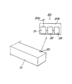
建物検査システムの概略構成について説明する。図1は建物検査システム1の構成要素の説明図であり、図2は構成部材10に付帯されるICタグ20の説明図である。
(Schematic configuration of building inspection system)
A schematic configuration of the building inspection system will be described. FIG. 1 is an explanatory diagram of components of the
図1に示すように、本実施形態の建物検査システム1は、建物の全ての構成部材に付帯されるICタグ20により構成される位置情報形成手段2と、位置情報形成手段2により形成されたICタグ20の相対的な位置関係を示した相対位置情報を取得するための相対位置情報取得手段3と、建物完成時のICタグ20の相対位置である完成位置情報が予め記憶された完成位置情報記憶手段4と、相対位置情報取得手段3から得たICタグ20間の相対位置情報と完成位置情報記憶手段4に記憶された完成位置情報とを比較して各構成部材が正しく配置されているか否かを検討する比較検討手段5と、を有する。
As shown in FIG. 1, the
また、図2に示すように、位置情報形成手段2は、信号を送受信するための送受信手段21と、ICタグ20が貼付された構成部材10の情報が記憶され送受信手段21により送受信された信号により情報の読み書きがなされる記憶手段23と、送受信手段21及び記憶手段23を制御する制御手段22とを、各構成部材10に付帯されたICタグ20に一体的に配設している。尚、ここで示す構成部材10は、ICタグ20が付帯された構成部材一般を示しており、ある特定の部材を示したものではない。
Further, as shown in FIG. 2, the position information forming means 2 includes a transmission / reception means 21 for transmitting / receiving signals and a signal transmitted / received by the transmission / reception means 21 in which information on the
(建物検査システムの詳細構成)
上述のように、建物検査システム1は、位置情報形成手段2、相対位置情報取得手段3、完成位置情報記憶手段4及び比較検討手段5によって構成される。次に、各手段の詳細構成を具体的に説明する。
(Detailed structure of building inspection system)
As described above, the
位置情報形成手段2は、各構成部材に付帯されるICタグ20間で情報のやり取りが行われることによって構成される。図2に示すように、ICタグ20は、アンテナ20aと半導体ICチップ20bから構成される。尚、ICタグ20間の情報のやり取りについては後に詳述する。
The position information forming means 2 is configured by exchanging information between the
半導体ICチップ20bには、アンテナ20aを介して信号の送受信を行う送受信手段21、CPU等の制御手段22、メモリ等の記憶手段23、及び不図示の電源が実装されている。
The
記憶手段23には、ICタグ20が付帯する構成部材10の部材情報が予め記憶されている。ここで、部材情報とは、構成部材10の寸法等の大きさ、構成部材10に付帯されたICタグ20の位置、構成部材10の種類(柱、壁、梁など)、部品番号、材質、他の部材が組み付けられるジョイント位置等、構成部材10を示す情報をいう。
In the storage means 23, member information of the
相対位置情報取得手段3としては、ICタグのリーダライタを用いることができる。相対位置情報取得手段3は、全てのICタグ20間の情報のやり取りによって、全てのICタグ20の相対的な位置関係が形成された後、任意に特定した特定ICタグから相対位置情報を読取るものである。
As the relative position
完成位置情報記憶手段4としては、パーソナルコンピュータ等のハードディスクを用いることができる。完成位置情報記憶手段4には、予め3次元CAD等のコンピュータで構築された仮想の建物の情報(CADデータ)に基づいて、完成位置情報が記憶されている。前記完成位置情報には、建物の全ての構成部材の状況、ICタグに含まれる部材情報、構成部材に付帯されるICタグの位置及び完成時のICタグ間の相対的な位置等が含まれる。 As the completion position information storage means 4, a hard disk such as a personal computer can be used. Completion position information storage means 4 stores completion position information based on information (CAD data) of a virtual building previously constructed by a computer such as a three-dimensional CAD. The completion position information includes the status of all the structural members of the building, the member information included in the IC tag, the position of the IC tag attached to the structural member, the relative position between the IC tags when completed, and the like. .
比較検討手段5としては、コンピュータ等のCPUを用いることができる。比較検討手段5では、相対位置情報取得手段3によって得られた前記相対位置情報と、完成位置情報記憶手段4に入力された前記完成位置情報とを照合し、比較検討する。比較検討した後、前記相対位置情報と前記完成位置情報とが一致した場合には、建物の構成部材は確実に組み付けられていると判断し、その旨のメッセージをディスプレイ等の表示手段に表示する。一方、比較検討した後、前記相対位置情報と前記完成位置情報とが一致しない場合には、建物の構成部材が確実に組み付けられていないと判断し、不具合のある場所とともに組み付けられていない旨のメッセージを表示手段に表示する。
As the comparative examination means 5, a CPU such as a computer can be used. The comparison review unit 5 compares the relative position information obtained by the relative position
(ICタグ20間の情報のやり取りの方法について)
ICタグ20間の情報のやり取りの方法について、図3を用いて説明する。図3はICタグ20間の情報のやり取りの説明図である。本発明の特徴としては、各ICタグ20が他の近隣のICタグを検知すること、ICタグ間で情報を中継すること、相対位置情報取得手段3によって特定された特定ICタグを基準として相対位置情報を構築すること、が挙げられる。このようにICタグ間で中継して情報をやり取りすることにより、各ICタグの記憶手段23の記憶容量を減らすことができる。このため、ICタグの小型化が可能となる。また、やり取りする情報の容量が少なくて済むため、通信速度が速くなり、相対位置情報を取得し、建物の検査が完了するまでの時間も短縮することができる。また、中継をすることにより、遠くのICタグまで電波を到達させなくてもよいため、消費電力を低く抑えることができる。
(How to exchange information between IC tags 20)
A method of exchanging information between the IC tags 20 will be described with reference to FIG. FIG. 3 is an explanatory diagram of the exchange of information between the IC tags 20. The feature of the present invention is that each
図3を用いて、相対位置情報取得手段3と複数のICタグ20とで、どのようなやり取りが行われるかを具体的に説明する。尚、本例においては、説明の都合上ICタグ20が近隣のICタグを1つずつ検知しているが、同時に複数のICタグを検知することもできる。
With reference to FIG. 3, what is exchanged between the relative position
図3において、3つのICタグ20A、20B、20Cの記憶手段23には、部材情報としてA、B、Cの情報が記憶されているとし、ICタグ20A、20B、20Cの順で、相対位置情報取得手段3からの距離が遠くなっているとする。
In FIG. 3, the storage means 23 of the three
図3(a)に示すように、相対位置情報取得手段3は、建物のICタグのうち1つを特定する。ここでは、部材情報Aが記憶手段23に記憶されているICタグ20Aを特定した。次に、相対位置情報取得手段3は、ICタグ20Aに対して、近隣のICタグに対して検知信号を発信するように指令する。この指令に基づいて、ICタグ20Aからは検知信号が周囲へ発信される。ここで検知信号は、ICタグ20Aから一定の範囲全域に送信される。
As shown in FIG. 3A, the relative position
図3(b)に示すように、ICタグ20Aの近隣にあるICタグ20Bは、ICタグ20Aからの検知信号を受信する。するとICタグ20Bの制御手段22は、ICタグ20Bが次回からICタグ20Aからの信号を受けることを記憶手段23に記憶した後、ICタグ20Aに向けて、ICタグ20Bが検知信号を受信し、ICタグ20Aの近隣にはICタグ20Bがあるという受信信号を送信する。この情報をICタグ20Aが受信すると、ICタグ20Aの制御手段22は、当該受信信号をそのまま中継して相対位置情報取得手段3に送信する。このように、検知信号を受けたICタグ20Bからは、受信信号がICタグ20Aを中継して相対位置情報取得手段3まで伝達される。これにより、相対位置情報取得手段3は、ICタグが、ICタグ20A、20Bの順で配置されていることを認識することができる。
As shown in FIG. 3B, the
図3(c)に示すように、ICタグ20A、20Bの順で配置されていることを認識した相対位置情報取得手段3は、ICタグ20Aを中継して、ICタグ20Bに対して検知信号を発信するように指令する。この指令に基づいて、ICタグ20Bからは検知信号が発信される。
As shown in FIG. 3 (c), the relative position information acquisition means 3 that has recognized that the IC tags 20A and 20B are arranged in this order relays the
図3(d)に示すように、ICタグ20Bの近隣にあるICタグ20Cは、ICタグ20Bからの検知信号を受信する。すると、前述と同様に、ICタグ20B、ICタグ20Aを中継して、相対位置情報取得手段3にまで情報を伝達する。これにより、相対位置情報取得手段3は、ICタグが、ICタグ20A、20B、20Cの順で配置されていることを認識することができる。
As shown in FIG. 3D, the
図3(e)に示すように、ICタグ20A、20B、20Cの順で配置されていることを認識した相対位置情報取得手段3は、ICタグ20A、20Bを中継して、ICタグ20Cに対して検知信号を発信するように指令する。この指令に基づいて、ICタグ20Cからは検知信号が発信される。
As shown in FIG. 3E, the relative position
図3(f)に示すように、ICタグ20Cの送受信手段21が、他のICタグからの受信信号を一定時間受信しなかった場合、制御手段22はICタグ20Cの近隣には他のICタグ20はないという情報を、ICタグ20Bに向けて送信する。この情報はICタグ20B、ICタグ20Aを中継して、相対位置情報取得手段3にまで伝達する。これにより、相対位置情報取得手段3は、ICタグが、ICタグ20A、20B、20Cの順で配置され、ICタグ20Cよりも遠くにはICタグがないことを認識することができる。
As shown in FIG. 3 (f), when the transmission / reception means 21 of the
(ICタグによる相対位置情報の形成方法)
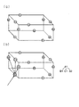
前述した方法で、相対位置情報取得手段3は、特定ICタグを基準としてICタグの並びを把握することができる。次に、建物の構成部材を組み付けた後に、ICタグの前述の情報のやり取りを行うことにより、相対位置情報をどのように形成するかを図4乃至図6を用いて説明する。図4乃至図6は建物とICタグ20の模式図及び相対位置情報取得手段により認識されたICタグの相対位置情報のツリー図である。
(Method for forming relative position information by IC tag)
By the method described above, the relative position
まず、構成部材を組み付けた建物の立体的な模式図を図4(a)に示す。立体的な模式図の各辺は構成部材を示し、丸付きのアルファベットA1〜A2、B1〜B4、C1〜C2、D1〜D2、E1〜E2は、それぞれICタグ20を示す。同一のアルファベットで示されたものは、同一の部材情報がICタグ20の記憶手段23に記録されている同一の構成部材とする。
First, FIG. 4A shows a three-dimensional schematic diagram of a building in which components are assembled. Each side of the three-dimensional schematic diagram indicates a component, and circled alphabets A1 to A2, B1 to B4, C1 to C2, D1 to D2, and E1 to E2 indicate the
図4(b)に示すように、相対位置情報取得手段3によって、例えばICタグ20A1が特定ICタグとされる。すると、相対位置情報取得手段3は、特定ICタグ20A1に対し、検知信号を発信するように指令する。すると、ICタグ20Aから一定範囲にあるタグ(図中破線のタグ)に検知信号が発信される。
As shown in FIG. 4B, the relative position
前記検知信号を受信したICタグ20B1、ICタグ20C1、ICタグ20B1は、受信信号をICタグ20A1を中継して、相対位置情報取得手段3に送信する。ここで受信信号は、前記検知信号を発信したICタグ20A1から近い順に相対位置情報取得手段3により認識される。
The IC tag 20B1, the IC tag 20C1, and the IC tag 20B1 that have received the detection signal relay the received signal to the relative position
図5(a)に示すように、相対位置情報取得手段3は、ICタグ20A1を中継して、最もICタグ20A1から近い側のICタグ20B1に対し、検知信号を発信するように指令する。すると、ICタグ20B1は、ICタグ20B1から一定範囲にあるタグ(図中破線のタグ)に検知信号を発信する。すると、前記検知信号を受信したICタグ20D2が、相対位置情報取得手段3に対して受信信号を送信する。
As shown in FIG. 5A, the relative position
尚、この場合、ICタグ20B1から発信された検知信号の一定範囲には、ICタグ20C1も含まれるが、ICタグ20C1は既に検知されている。ここで、ICタグ20C1の制御手段22は、受信信号を相対位置情報取得手段3には送信しない。これにより、情報の重複を防ぐことができる。具体的には、一度、ICタグ20が検知信号を受信した場合には、記憶手段23に既に検知信号を受信したことを記憶する等して、これを行うことができる。尚、図面においては、既に検知されたICタグ20を円で囲って示す。
In this case, the IC tag 20C1 is included in a certain range of the detection signal transmitted from the IC tag 20B1, but the IC tag 20C1 has already been detected. Here, the control means 22 of the IC tag 20C1 does not transmit the received signal to the relative position information acquisition means 3. Thereby, duplication of information can be prevented. Specifically, once the
以上の手順を踏むことにより、相対位置情報取得手段3は、ICタグ20A1、ICタグ20B1、ICタグ20D2の並びを認識することができる。
By following the above procedure, the relative position
図5(b)に示すように、相対位置情報取得手段3は、ICタグ20A1を中継して、2番目にICタグ20A1から近い側のICタグ20C1に対し、検知信号を発信するように指令する。するとICタグ20C1は、前述と同様に検知信号を発信する。前記検知信号を受信したICタグ20D1が、相対位置情報取得手段3に対して受信信号を送信する。尚、前述と同様、ICタグ20D2も検知信号の一定範囲に入るが、既にICタグ20B1により検知されているため、ICタグ20D2が相対位置情報取得手段3に対して受信信号を送信することはない。
As shown in FIG. 5B, the relative position information acquisition means 3 relays the IC tag 20A1, and instructs the IC tag 20C1 closest to the second IC tag 20A1 to send a detection signal. To do. Then, the IC tag 20C1 transmits a detection signal as described above. The IC tag 20D1 that has received the detection signal transmits a reception signal to the relative position
図5(c)に示すように、相対位置情報取得手段3は、ICタグ20A1を中継して、3番目にICタグ20A1から近い側のICタグ20B2に対し、検知信号を発信するように指令する。するとICタグ20B2は、前述と同様に検知信号を発信する。前記検知信号は近隣のICタグ20C1、ICタグ20D1に達するが、既に検知されているため、前述と同様に、相対位置情報取得手段3に対して受信信号を送信することはない。これにより、この後相対位置情報取得手段3は、ICタグ20A1、ICタグ20B2を中継して検知手段を発信する指令を出すことはない。
As shown in FIG. 5C, the relative position information acquisition means 3 relays the IC tag 20A1 and instructs the IC tag 20B2 closest to the third IC tag 20A1 to send a detection signal. To do. Then, the IC tag 20B2 transmits a detection signal as described above. The detection signal reaches the neighboring IC tag 20C1 and IC tag 20D1, but since the detection signal has already been detected, the reception signal is not transmitted to the relative position
このようにして、相対位置情報取得手段3は、ICタグ20A1からの検知信号を受信したICタグ20B1、ICタグ20C1及びICタグ20B2に対して、一通り検知信号の発信指令を出す。
In this way, the relative position
図6(a)に示すように、次に相対位置情報取得手段3は、最もICタグ20A1から近い側のICタグ20B1を中継して、ICタグ20D2に対して検知信号を発信するように指令する。この検知信号を受信したICタグ20E1は、相対位置情報取得手段3に対して受信信号を送信する。 As shown in FIG. 6A, the relative position information acquisition means 3 then instructs to relay the IC tag 20B1 closest to the IC tag 20A1 and to send a detection signal to the IC tag 20D2. To do. The IC tag 20E1 that has received this detection signal transmits a reception signal to the relative position information acquisition means 3.
以上の作業を繰り返すことにより、各ICタグ20間では、特定ICタグ20A1を基準として、情報を中継することにより、ICタグ間の相対位置情報を形成する(図6(b)参照)。 By repeating the above operation, the relative position information between the IC tags is formed between the IC tags 20 by relaying information with the specific IC tag 20A1 as a reference (see FIG. 6B).
〔第2実施形態〕
本発明の第2実施形態について、図7及び図8を用いて説明する。前述と同様の構成については、同じ符号を付すことで、説明を省略する。前述の実施形態と本実施形態とは、ICタグによる相対位置情報の形成方法のみが異なる。
[Second Embodiment]
A second embodiment of the present invention will be described with reference to FIGS. About the structure similar to the above, description is abbreviate | omitted by attaching | subjecting the same code | symbol. The above-described embodiment and this embodiment differ only in the method of forming relative position information using an IC tag.
(ICタグによる相対位置情報の形成方法)
構成部材を組み付けた建物の立体的な模式図を図7(a)に示す。符号の付し方は前述の実施形態と同様である。ここで、相対位置情報取得手段3によって、例えばICタグ20A1が特定ICタグとされる。この特定ICタグ20A1から、相対位置情報取得手段3が相対位置情報を取得することになる。
(Method for forming relative position information by IC tag)
FIG. 7A shows a three-dimensional schematic diagram of the building in which the constituent members are assembled. The way of attaching the reference numerals is the same as in the above-described embodiment. Here, for example, the IC tag 20A1 is set as the specific IC tag by the relative position information acquisition means 3. The relative position information acquisition means 3 acquires the relative position information from the specific IC tag 20A1.
ここで、本実施形態の前記位置情報形成手段は、各ICタグ間のやり取りを行って、各ICタグが隣接する構成部材に付帯したICタグを検索し、相対位置情報を形成する。 Here, the position information forming unit of the present embodiment performs exchange between the IC tags, searches for the IC tag attached to the adjacent structural member of each IC tag, and forms relative position information.
この構成により、図7(b)に示すように、まず特定ICタグ20A1の制御手段22は、送受信手段21から近隣のICタグ20に向かって検索信号を発する。これにより、近隣にあるICタグ20(ICタグ20B1、ICタグ20C1、ICタグ20B2、ICタグ20E1、ICタグ20E2)が、前記検索信号を受信する。ここで本実施形態においては、ICタグ20A1に隣接する構成部材に付帯されているICタグ20B1、ICタグ20B2、ICタグ20E1、ICタグ20E2は、受信信号をICタグ20A1に送信するが、ICタグ20A1と隣接しない構成部材に付帯されているICタグ20C1は隣接しない構成部材であるため、相対位置情報が形成できず、ICタグ20C1はICタグ20A1に対して受信信号を送信しない。
With this configuration, as shown in FIG. 7B, first, the control means 22 of the specific IC tag 20A1 issues a search signal from the transmission / reception means 21 toward the neighboring
したがって、隣接する構成部材に付帯されているICタグ20B1、ICタグ20B2、ICタグ20E1、ICタグ20E2のみが、ICタグ20A1に向かって受信信号を送信することとなる。このようにやり取りを行って形成された相対位置情報(図7(b)右側のツリー図)は、特定ICタグ20A1を中継して、相対位置情報取得手段3から取得される。尚、図面においては、既に検出した構成部材を示す線を、二重線でなぞることで示す。 Therefore, only the IC tag 20B1, the IC tag 20B2, the IC tag 20E1, and the IC tag 20E2 attached to the adjacent components transmit the reception signal toward the IC tag 20A1. The relative position information (the tree diagram on the right side of FIG. 7B) formed through such exchange is acquired from the relative position information acquisition means 3 via the specific IC tag 20A1. In the drawings, lines indicating already detected components are shown by tracing with double lines.
次に図8(a)に示すように、特定ICタグ20Aの制御手段22は、検出したICタグ20B1、ICタグ20B2、ICタグ20E1、ICタグ20E2に対して、隣接するICタグ20が何かを検索するように指令を出す。
Next, as shown in FIG. 8A, the control means 22 of the
例えば、特定ICタグ20Aの制御手段22が、隣接するICタグ20B1、ICタグ20B2、ICタグ20E1、ICタグ20E2のうち、ICタグ20B1に対して、隣接する構成部材のICタグ20を検索するように指令を出す。この指令を受けて、ICタグ20B1が検索信号を発信する。すると、当該検索信号を受信したICタグ20のうち、ICタグ20B1に隣接する構成部材に付帯しているICタグ20C1、ICタグ20D2が、受信信号をICタグ20B1に対して送信する。当該受信信号はICタグ20B1、ICタグ20A1に中継され、相対位置情報取得手段3に到達する。
For example, the control means 22 of the
次に特定ICタグ20Aの制御手段22は、隣接するICタグ20B1、ICタグ20B2、ICタグ20E1、ICタグ20E2のうち、ICタグ20B2に対して、隣接する構成部材のICタグ20を検索するように指令を出す。すると、指令を受けたICタグ20B2は、検出信号を発信する。当該検出信号を受信したICタグ20D1は受信信号をICタグ20B2に向けて送信する。ここで、ICタグ20E2は既に検出されているので、再び受信信号を送信することはない。
Next, the control means 22 of the
このやり取りを各ICタグ20間で情報を中継しつつ繰り返す。これにより、図8(a)の矢印で示し、右側のツリー図に示すように、順次、特定ICタグ20A1に隣接するICタグ20にさらに隣接するICタグ20C1、ICタグ20D2、ICタグ20D1、ICタグ20A2、ICタグ20B4、ICタグ20B3、が順に検出される。 This exchange is repeated while relaying information between the IC tags 20. As a result, as indicated by the arrows in FIG. 8A and as shown in the tree diagram on the right side, the IC tag 20C1, the IC tag 20D2, the IC tag 20D1, IC tag 20A2, IC tag 20B4, and IC tag 20B3 are detected in order.
最後に、ICタグ20C2が検索信号を受信すると、ICタグ20C2の受信信号がICタグ20D2、ICタグ20B1を中継して、特定ICタグ20A1に送信される。 Finally, when the IC tag 20C2 receives the search signal, the reception signal of the IC tag 20C2 is transmitted to the specific IC tag 20A1 via the IC tag 20D2 and the IC tag 20B1.
このようなやり取りを行うことにより、図8(b)に示すように、全てのICタグ20が検出され、ICタグ間の相対位置情報が形成される。 By performing such exchange, as shown in FIG. 8B, all the IC tags 20 are detected, and relative position information between the IC tags is formed.
尚、本実施形態においては、柱状と梁状の部材のみを使用して立体的な模式図を形成したが、壁や屋根のような部材についても使用することができる。 In the present embodiment, a three-dimensional schematic diagram is formed using only columnar and beam-shaped members, but members such as walls and roofs can also be used.
尚、実施形態では、建物の完成したときの検査の例を示したが、所定の中間完成時の中間検査に対しても、本発明を適用することができる。 In the embodiment, the example of the inspection when the building is completed is shown. However, the present invention can be applied to the intermediate inspection at a predetermined intermediate completion.
本発明の活用例として、建物以外の構造物にも使用することができる。例えば、建物以外で多くの構成部品を使用する自動車、航空機、船舶等にもこの技術を転用することが可能である。 As an application example of the present invention, it can also be used for structures other than buildings. For example, this technique can be diverted to automobiles, aircraft, ships, and the like that use many components other than buildings.
1 …建物検査システム
2 …位置情報形成手段
3 …相対位置情報取得手段
4 …完成位置情報記憶手段
5 …比較検討手段
10 …構成部材
20 …ICタグ
20a …アンテナ
20b …半導体ICチップ
21 …送受信手段
22 …制御手段
23 …記憶手段
DESCRIPTION OF
10 ... Components
20 ... IC tag
20a ... Antenna
20b Semiconductor IC chip
21 ... Transmission / reception means
22… Control means
23… Memory means
Claims (3)
前記相対位置情報を取得するための相対位置情報取得手段と、
建物完成後のICタグの相対位置である完成位置情報が予め記憶された完成位置情報記憶手段と、
前記相対位置情報取得手段から得たICタグ間の相対位置情報と前記完成位置情報記憶手段に記憶された完成位置情報とを比較して前記各構成部材が正しく配置されているか否かを検討する比較検討手段と、
を有することを特徴とする建物検査システム。 Position information forming means for acquiring information on the IC tag attached to each component of the building and forming relative position information between all the IC tags arranged in the building;
Relative position information acquisition means for acquiring the relative position information;
Completion position information storage means in which completion position information, which is the relative position of the IC tag after completion of the building, is stored in advance;
The relative position information between the IC tags obtained from the relative position information acquisition means and the completed position information stored in the completed position information storage means are compared to determine whether or not each of the constituent members is correctly arranged. A comparative study means;
A building inspection system characterized by comprising:
信号を送受信するための送受信手段と、
前記ICタグが貼付された構成部材の情報が記憶され前記送受信手段により送受信された信号により情報の読み書きがなされる記憶手段と、
前記送受信手段及び前記記憶手段を制御する制御手段とを、
前記各構成部材に付帯されたICタグに一体的に配設し、前記各構成部材に付帯されるICタグ間で情報を中継することにより、ICタグ間の相対位置情報を形成することを特徴とする請求項1に記載の建物検査システム。 The position information forming means includes
Transmitting and receiving means for transmitting and receiving signals;
Storage means for storing and reading information by signals transmitted and received by the transmission / reception means;
Control means for controlling the transmission / reception means and the storage means;
Relative position information between the IC tags is formed by integrally arranging the IC tags attached to the respective constituent members and relaying information between the IC tags attached to the respective constituent members. The building inspection system according to claim 1.
The building inspection system according to claim 1, wherein the position information forming unit forms the relative position information while searching for IC tags of adjacent components.
Priority Applications (1)
| Application Number | Priority Date | Filing Date | Title |
|---|---|---|---|
| JP2005041656A JP4553748B2 (en) | 2005-02-18 | 2005-02-18 | Building inspection system |
Applications Claiming Priority (1)
| Application Number | Priority Date | Filing Date | Title |
|---|---|---|---|
| JP2005041656A JP4553748B2 (en) | 2005-02-18 | 2005-02-18 | Building inspection system |
Publications (2)
| Publication Number | Publication Date |
|---|---|
| JP2006227961A JP2006227961A (en) | 2006-08-31 |
| JP4553748B2 true JP4553748B2 (en) | 2010-09-29 |
Family
ID=36989291
Family Applications (1)
| Application Number | Title | Priority Date | Filing Date |
|---|---|---|---|
| JP2005041656A Active JP4553748B2 (en) | 2005-02-18 | 2005-02-18 | Building inspection system |
Country Status (1)
| Country | Link |
|---|---|
| JP (1) | JP4553748B2 (en) |
Families Citing this family (2)
| Publication number | Priority date | Publication date | Assignee | Title |
|---|---|---|---|---|
| JP7215846B2 (en) * | 2018-08-10 | 2023-01-31 | 積水化学工業株式会社 | Inspection system, inspection method, and refractory material |
| JP7489279B2 (en) | 2020-09-24 | 2024-05-23 | センクシア株式会社 | Anchor frame and mounting construction management system |
Citations (3)
| Publication number | Priority date | Publication date | Assignee | Title |
|---|---|---|---|---|
| JP2001349057A (en) * | 2000-06-07 | 2001-12-21 | Mitsubishi Heavy Ind Ltd | Information storage medium and construction supporting method using it |
| JP2005327170A (en) * | 2004-05-17 | 2005-11-24 | Shimizu Corp | Quality check system in construction site |
| JP2006207183A (en) * | 2005-01-26 | 2006-08-10 | Hitachi Plant Technologies Ltd | Supporting system and method for positioning installation of construction material |
-
2005
- 2005-02-18 JP JP2005041656A patent/JP4553748B2/en active Active
Patent Citations (3)
| Publication number | Priority date | Publication date | Assignee | Title |
|---|---|---|---|---|
| JP2001349057A (en) * | 2000-06-07 | 2001-12-21 | Mitsubishi Heavy Ind Ltd | Information storage medium and construction supporting method using it |
| JP2005327170A (en) * | 2004-05-17 | 2005-11-24 | Shimizu Corp | Quality check system in construction site |
| JP2006207183A (en) * | 2005-01-26 | 2006-08-10 | Hitachi Plant Technologies Ltd | Supporting system and method for positioning installation of construction material |
Also Published As
| Publication number | Publication date |
|---|---|
| JP2006227961A (en) | 2006-08-31 |
Similar Documents
| Publication | Publication Date | Title |
|---|---|---|
| JP2007140886A (en) | Rfid built-in cable system, its manufacturing method, method of use, and rfid reader used for the same | |
| JP2008117039A (en) | Patrol assistance system, patrol assistance method, patrol assistance program and program recording medium | |
| CN106933740B (en) | Star sensor software online fault monitoring system and monitoring method thereof | |
| US7583193B2 (en) | Method for supporting an antenna wiring, and a system | |
| JP4511964B2 (en) | production management system | |
| JP3910185B2 (en) | Tag unit reader | |
| JP4553748B2 (en) | Building inspection system | |
| JP2007058713A (en) | Danger avoidance system | |
| US20140244971A1 (en) | Array of processor core circuits with reversible tiers | |
| CN106250384A (en) | information retrieval system and information retrieval method | |
| US20060287762A1 (en) | Method and apparatus for planning the installation position of RFID tags | |
| JP2009009521A (en) | Overlook prevention method for radio tag and radio tag information management system using the same | |
| JP2009064282A (en) | Rfid tag, rfid system, manufacturing device for rfid tag, and manufacturing method therefor | |
| CN100361433C (en) | Communication device using three step communication buffer storage | |
| JP2009205603A (en) | Ic tag, production line system, and inspection line system | |
| CN205563570U (en) | High -speed railway station room MEP pipeline collision detection system based on BIM | |
| JP6788451B2 (en) | Crew operation support system | |
| CN110661554A (en) | Radio frequency circuit, radio frequency tag and communication system | |
| WO2017159781A1 (en) | Tag management device, tag management method, and program | |
| JP6459779B2 (en) | RFID built-in terminal module and RFID identification number provisional numbering method | |
| JP2007026275A (en) | Reader-writer monitoring system, reader-writer monitoring method, reader-writer monitoring computer, and reader-writer | |
| CN103914714B (en) | For the initialized system of electronic tag | |
| JP5339116B2 (en) | Civil engineering structure and civil engineering structure management system | |
| CN113326212B (en) | Data processing method and device and related equipment | |
| US7520432B2 (en) | Sensor system |
Legal Events
| Date | Code | Title | Description |
|---|---|---|---|
| RD02 | Notification of acceptance of power of attorney |
Free format text: JAPANESE INTERMEDIATE CODE: A7422 Effective date: 20080131 |
|
| A621 | Written request for application examination |
Free format text: JAPANESE INTERMEDIATE CODE: A621 Effective date: 20080206 |
|
| A977 | Report on retrieval |
Free format text: JAPANESE INTERMEDIATE CODE: A971007 Effective date: 20100702 |
|
| TRDD | Decision of grant or rejection written | ||
| A01 | Written decision to grant a patent or to grant a registration (utility model) |
Free format text: JAPANESE INTERMEDIATE CODE: A01 Effective date: 20100713 |
|
| A01 | Written decision to grant a patent or to grant a registration (utility model) |
Free format text: JAPANESE INTERMEDIATE CODE: A01 |
|
| A61 | First payment of annual fees (during grant procedure) |
Free format text: JAPANESE INTERMEDIATE CODE: A61 Effective date: 20100713 |
|
| FPAY | Renewal fee payment (event date is renewal date of database) |
Free format text: PAYMENT UNTIL: 20130723 Year of fee payment: 3 |
|
| R150 | Certificate of patent or registration of utility model |
Ref document number: 4553748 Country of ref document: JP Free format text: JAPANESE INTERMEDIATE CODE: R150 Free format text: JAPANESE INTERMEDIATE CODE: R150 |
|
| FPAY | Renewal fee payment (event date is renewal date of database) |
Free format text: PAYMENT UNTIL: 20130723 Year of fee payment: 3 |
|
| S531 | Written request for registration of change of domicile |
Free format text: JAPANESE INTERMEDIATE CODE: R313531 |
|
| FPAY | Renewal fee payment (event date is renewal date of database) |
Free format text: PAYMENT UNTIL: 20130723 Year of fee payment: 3 |
|
| R350 | Written notification of registration of transfer |
Free format text: JAPANESE INTERMEDIATE CODE: R350 |
|
| S531 | Written request for registration of change of domicile |
Free format text: JAPANESE INTERMEDIATE CODE: R313531 |
|
| R350 | Written notification of registration of transfer |
Free format text: JAPANESE INTERMEDIATE CODE: R350 |