JP4553501B2 - Endoscope shaft with movable distal end - Google Patents
Endoscope shaft with movable distal end Download PDFInfo
- Publication number
- JP4553501B2 JP4553501B2 JP2001060628A JP2001060628A JP4553501B2 JP 4553501 B2 JP4553501 B2 JP 4553501B2 JP 2001060628 A JP2001060628 A JP 2001060628A JP 2001060628 A JP2001060628 A JP 2001060628A JP 4553501 B2 JP4553501 B2 JP 4553501B2
- Authority
- JP
- Japan
- Prior art keywords
- endoscope shaft
- distal end
- clock
- endoscope
- longitudinal direction
- Prior art date
- Legal status (The legal status is an assumption and is not a legal conclusion. Google has not performed a legal analysis and makes no representation as to the accuracy of the status listed.)
- Expired - Lifetime
Links
Images


Classifications
-
- A—HUMAN NECESSITIES
- A61—MEDICAL OR VETERINARY SCIENCE; HYGIENE
- A61B—DIAGNOSIS; SURGERY; IDENTIFICATION
- A61B1/00—Instruments for performing medical examinations of the interior of cavities or tubes of the body by visual or photographical inspection, e.g. endoscopes; Illuminating arrangements therefor
- A61B1/005—Flexible endoscopes
-
- A—HUMAN NECESSITIES
- A61—MEDICAL OR VETERINARY SCIENCE; HYGIENE
- A61B—DIAGNOSIS; SURGERY; IDENTIFICATION
- A61B1/00—Instruments for performing medical examinations of the interior of cavities or tubes of the body by visual or photographical inspection, e.g. endoscopes; Illuminating arrangements therefor
- A61B1/012—Instruments for performing medical examinations of the interior of cavities or tubes of the body by visual or photographical inspection, e.g. endoscopes; Illuminating arrangements therefor characterised by internal passages or accessories therefor
- A61B1/018—Instruments for performing medical examinations of the interior of cavities or tubes of the body by visual or photographical inspection, e.g. endoscopes; Illuminating arrangements therefor characterised by internal passages or accessories therefor for receiving instruments
Abstract
Description
【0001】
【発明の属する技術分野】
本発明は運動し得る遠位端部と操作デバイスとを備えた内視鏡シャフトに関する。さらに詳しくは、当該操作デバイスが内視鏡シャフトを介して内視鏡シャフトの操作のための当該遠位端部に操作自在に接続された内視鏡シャフトに関する。
【0002】
【従来の技術】
内視鏡は、とくに身体の管状臓器内の空洞ないしは内腔を診察するための医療用の器具である。たとえば医療目的でとくに身体の管状臓器内の空洞ないしは内腔を診察するための器械である。内視鏡は、とくに食道、胃、胃から十二指腸、肛門から腸、尿道、膀胱および尿管を診察するために使用される。内視鏡にはほとんどの場合、前端に取り付けられた照明器具と内視鏡の前方に位置する内腔の領域を視覚的に検知するための光学系が設けられている。最近まで内視鏡の前端部で検知された光学的情報は、通常、内視鏡を貫いている光ファイバーによって内視鏡の操作端に伝達され、内視鏡前端のカメラチップ(camera chip)の挿入と、電気的な画像の伝達および得られた光学的情報のモニター上での描写とが現在の先行技術を構成している。
【0003】
そのうえ、内視鏡は、通常、たとえば組織標本を採取するための鉗子、生検針、加熱したた切開用ワイヤー、小型のメス等のような様々な作業器具を挿入し、操作できるのでそのように呼ばれる作用導管(working conduit)を含んでいる。最後に、一般には、洗浄するための流体導管と、内視鏡の先端を様々な方向に屈曲させるための操作ワイヤとが設けられている。当該操作ワイヤは、内視鏡シャフト内の個々の導管を経てその前端ないしは遠位端に向けてガイドされ、該内視鏡シャフトの反対方向において160度まで三次元的に曲げられる。
【0004】
内視鏡はこれまで、圧力に対して剛性をもつ(pressure-stiff)内視鏡および/または内視鏡シャフトを本体から突き出ている内視鏡の部分から身体内へ押し入れることによって身体内に挿入されていた。内視鏡のかかる導入方法はとくに結腸鏡の場合には特別に困難で長い時間がかかるが、それは腸には屈曲部やしばしば峡部があるためである。したがって、結腸鏡検査はこれまで患者にとって不快な費用が高くつく検査であり、このため広範に適用することはほとんど考慮に入れられていなかった。さらに、結腸鏡を取り扱えるのは、この問題に関して経験を積んだ医師に限られている。
【0005】
【発明が解決しようとする課題】
このため、オペレータに与えられる診断上の操作フィーリングに関して本質的な問題を惹起している。すなわち、腸が診断されるとき、遠位端の曲げプロセスのあいだに腸壁が傷つけられる危険性がある。そのうえ、診断され、処置されるべき領域に当該遠位端を正確に位置づけることができなければならず、所定の曲げプロセスののち、必用なら、充分な柔軟性と同時に充分な剛性が要求される。
【0006】
叙上の問題に鑑みて、本発明の目的は、所定の曲げ位置に達したときに、充分な柔軟性と充分な剛性とを保証し、そのうえオペレータに充分な診断上の操作フィーリングを与える内視鏡の遠位端の構造を提供することである。
【0007】
【課題を解決するための手段】
本発明によれば、この目的は、運動し得る遠位端部と操作デバイスとを備えた内視鏡シャフトであって、
該操作デバイスが内視鏡シャフトを介して内視鏡シャフトの操作のための当該遠位端部に操作自在に接続され、
前記遠位端部が、長手方向に積み重ねられた複数の膨出体を備え、
該複数の膨出体のうちの2つが互いに直径方向に設けられて1つの層を形成し、長手方向に直接隣接する前記層の2対の位相が互いに90度だけずらされてなることを特徴とする内視鏡シャフトによって達成される。
【0008】
長手方向において個々の膨出体が1つの層では12時の方向と6時の方向とに配列され、該1つの層に隣接する層では3時の方向と9時の方向とに交互に配列されてなる構成が得られる。この方法では、ベローズが膨張したり、収縮したりするときに、同一の角位置を有するベローズを同期させて操作することによって意図された方向への遠位端のベンドオフ(bend-off)を達成することができ、該遠位端の所定の角位置に達したとき、前記膨出体がこの位置に固定され、該遠位端の固定が維持される。
【0009】
本発明の請求項1によって液圧ないしは油圧または空気圧によって操作し得るベローズとして膨出体を形成すると、たとえば、単純で、操作の少ない膨張モードが、たとえば操作者に充分な診断上の操作フィーリングを与えるハンドポンプの形体における同期して形成された圧力媒体源によって引き出せるので好ましい。
【0010】
本発明のさらに有利な実施の形態は、他の従属クレームの主題である。
【0011】
【発明の実施の形態】
添付図面を参照しながら本発明の実施の形体について、以下に詳細に述べる。
【0012】
図1は本発明の一実施の形態にかかわる内視鏡の遠位端の概要を示す断面図、図2は図1の遠位端の上面図、図3は本発明の一実施の形態にかかわる内視鏡の膨出体の構造を示す説明図、図4は本発明の一実施の形態にかかわる内視鏡シャフトの可動遠位端を構成している複数の膨出体を示す斜視図である。
【0013】
図1では、本発明の好ましい実施態様にしたがっている内視鏡シャフトの可動先端部分が略図として示されている。
【0014】
図1から読み取ることができるように、本発明にしたがっている内視鏡シャフトの可動先端部分1は長手方向に並列させられたおよび/または積み重ねられた複数の本体2、3、4を備えており、各層は相互に対して直径方向に(ないしは正反対)に配列された2つの本体から形成されている。
【0015】
図2は略図として示された可動先端部分の平面図を示している。したがって、各本体2、3、4は円周方向に見られる中央部分で膨出体6を形成する半円形リング状ディスク素子5から構成されている。半円形リング状ディスク5の2つの各端面では、ディスク5の厚さの方向に伸長している切り欠き7、7′が好ましくは半円形で形成されている。半円形リング状ディスク5は、対向する切り欠き7、7;7′、7′が各端面で2つの正反対に向合う貫通孔9、9′を限定するようにそれの2つの端面8、8′で各層において相互に隣接して配列されている。
【0016】
さらに図1から読み取ることができるように、先端部分の長手方向において直接に隣接する対の本体はさらに位置が90度ずれている。これによって膨出体6は1つの層に関して3時と6時の位置に、および各々隣の層上では12時と6時の位置に交互に配列されている。
【0017】
本実施の形態によれば、膨出体6は空気圧または液圧(たとえば油圧)により作動させることのできる伸縮ベローズとして形成される。あるいはまた、もちろん膨出体6を圧電素子として形成することも可能である。
【0018】
伸縮ベローズの場合における膨出体6は、可動先端部の旋回および/またはベンドオフ機構を形成する。このために、同一の角位置を有するすべてのベローズ、すなわち12時の位置、3時の位置、6時の位置および9時の位置にあるベローズは相互に結合されている。この結合は、機械的および液圧(油圧)および/または空気圧の両方で同一屈曲位置を有する2個の長手方向に離間したベローズを接続するダクト10から構成され、これらの複数のダクト10はそれらの間に取り付けられた対の本体の貫通孔9、9′を通って伸長している。その結果、個々の層がバラバラになるのを防止するために、液圧(油圧)および/または空気圧による流体連絡並びに機械的結合が複数のダクト10によって作り出される。
【0019】
図1によれば、ベローズは主として半円形リング状ディスク5の対向する扁平な側に用意されており、それを通ってリング状ディスク5が伸長している貫通孔11によって相互に液体連絡(ないしは連通)している。
【0020】
図2から明らかであるるように、各層について全可動先端部分1に沿って伸長していて外科用器具、補助器具または光学装置を導入するための作用導管を形成する中央貫通孔12は、本発明にしたがって半円形リング状ディスク5を並列させることによって形成されている。
【0021】
本発明による可動先端部分の機能原理は次のようにまとめることができる:
たとえば作動油(ないしは作動流体)のような圧力媒体が選択された角位置で複数のダクト10を通して液体結合ベローズ内にポンプで注ぎ込まれると、これはベローズが先端部分1の長手方向に実質的に拡大することを惹起し、これによって半円形リング状ディスク5はこの角位置の領域で互いに離間している。他の各角位置では圧力が印加されず、および/または圧力がその他の全ベローズから開放されるので、これは2個のリング状ディスク5から構成される各層が傾くことを惹起し、それによって先端部分は徐々にそれの全長手伸長部分にわたって屈曲する。油圧流体が加圧されたベローズによって多量に注入されるほど、ほぼ160度の屈曲が達成できるまで先端部分の屈曲度はより大きくなる。
【0022】
運動方向におけるそうした屈曲運動は、もちろん相違する角位置、たとえばそれを90度ずれた角位置でベローズを加圧することによって重ね合わせることができ、それによって結果として先端部分のある種の回転運動が生じる。さらにまた、相互に長手方向に間隔を空けて離れた全ベローズのすべての可能性のある伸長領域において先端部分を長手方向で移動または収縮させることができるように全角位置で全ベローズに圧力を適用する、または圧力を解除することも可能である。
【0023】
可動先端部分の先端部が特定の屈曲位置を採用するとすぐに、1または複数の角位置の各ベローズの加圧が停止され、それによって先端部分は油圧流体の圧縮不能な特性のためにこの屈曲位置で固定して維持される。
【0024】
この固定はベローズ自体の半径方向における弾性に依存するが、このとき各半円形リング状ディスクの設計に関しては、下記で具体的な設計によって説明されるように、長手方向においては弾性が良好であるが半径方向ではできる限り剛性の構造であるように努力されている。
【0025】
図1からさらに読み取ることができるように、図1に従った最下層の半円形リング状ディスク5は油圧パイプシステムを結合するための連結スリーブ13を含んでいる。この図には示されていないこの油圧パイプシステムは、実質的にその中に形成された作用導管内で内視鏡シャフトを通って誘導され、中央油圧源に接続されているいずれも図示されていない4本の導管を含んでいる。油圧源としては好ましくは、圧力が1つの角位置のベローズに適用されたときに対向する角位置にあるベローズ内の圧力が解放されるような方法で相互から独立してもしくは結合して操作可能な4個の個別ポンプから構成される手動操作型の圧力ポンプが適している。各々対向する列のベローズにおいて圧力の印加と圧力の解放との間のそうした相互関係があると、先端部分の可動性はさらに増加させることができ、位置決め能力を向上させることができる。
【0026】
そうした圧力ポンプは、さらにたとえば腸の側から括約筋の領域における腸壁の探索さえ可能にする。
【0027】
図3の(a)〜(d)には、半円形のリング状ディスク5の設計が詳細に示されている。そこから読み取ることができるように、リング状ディスク5は中空間隙を形成する所定厚さを有する基部として機能する合成体から構成される。この本体の壁はベローズ14を形成できるように半径方向の外側で少なくとも1回内側に折り畳まれている。
【0028】
リング状ディスク5の相互に対向する側面15、16では、整列してリング状体5の中空内に開いて配列されている連結スリーブ17、18が形成されている。連結スリーブ17、18はリング状ディスク5と一体型として形成することができる、またはその上に溶接することもできる。リング状ディスク5は、好ましくは円周方向において半径方向の外側および半径方向の内側に沿って相互に融着されている外皮の2つの半分から構成される。
【0029】
半円形切り欠き7、7′はリング状ディスク5の厚さの方向に半円形リング状ディスク5の両端面8、8′で形成されている。
【0030】
図4には可動先端部分が構造的に示されている。
【0031】
そこから明らかであるように、それらの各端面8、8′で同時に並列させられた上記で説明された2個のリング状ディスク5が1つの層を形成しているが、このとき相互に直接隣接して配列される各層の対のリング状ディスクは位置が90度ずれている。長手方向で見られる角位置に位置するリング状ディスク5を固定するために、端面に形成された切り欠き7、7′によって1つの層において形成される貫通孔9、9′を通って伸長している連結スリーブ17、18は相互に接着または溶接されている。これによって上記のダクト10並びに長手方向に結合されたリング状ディスク5の機械的接続が達成される。
【0032】
上記の設計での合成材料の代わりの材料として、さらにもちろんゴムまたは積層ゴムもまた先端部分1に使用されてもよい。先端部分は、2つの最下層において自由連結スリーブ13が油圧シャフトに沿って油圧管と液体連絡するように内視鏡シャフトの端面上に融着される。
【0033】
本発明は、可動遠位端部と作動デバイスとを備えた内視鏡シャフトに関するものである。該作動デバイスは、操作のために内視鏡シャフトを介して遠位端部に操作自在に連結されている。該遠位端部は、長手方向に積み重ねられた複数の膨出体を備えており、該複数の膨出体のうちの2つが互いに直径方向に設けられて1つの層を形成し、該層と長手方向に直接隣接する他の1つの層の位相が互いに90度だけずれている。
【0034】
【発明の効果】
本発明によれば、所定の曲げ位置に達したときに、充分な柔軟性と充分な剛性とを保証し、そのうえオペレータに充分な診断上の操作フィーリングを与える内視鏡の遠位端の構造を提供することができる。
【図面の簡単な説明】
【図1】本発明の一実施の形態にかかわる内視鏡の遠位端の概要を示す断面図である。
【図2】図1の遠位端の上面図である。
【図3】本発明の一実施の形態にかかわる内視鏡の膨出体の構造を示す説明図である。
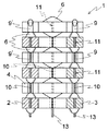
【図4】本発明の一実施の形態にかかわる内視鏡シャフトの可動遠位端を構成している複数の膨出体を示す斜視図である。
【符号の説明】
1 可動先端部分
2、3、4 本体
5 ディスク
6 膨出体
7、7′ 切り欠き
10 ダクト[0001]
BACKGROUND OF THE INVENTION
The present invention relates to an endoscope shaft having a movable distal end and an operation device. More specifically, the present invention relates to an endoscope shaft that is operably connected to the distal end portion for operation of the endoscope shaft via the endoscope shaft.
[0002]
[Prior art]
An endoscope is a medical instrument for examining a cavity or lumen in a tubular organ of the body. For example, for medical purposes, an instrument for examining a cavity or lumen in a tubular organ of the body. Endoscopes are used in particular to examine the esophagus, stomach, stomach to duodenum, anus to intestine, urethra, bladder and ureter. In most cases, an endoscope is provided with an illuminating device attached to the front end and an optical system for visually detecting a region of a lumen located in front of the endoscope. Until recently, optical information detected at the front end of the endoscope is usually transmitted to the operation end of the endoscope by an optical fiber penetrating the endoscope, and the camera chip (camera chip) at the front end of the endoscope is transmitted. Insertion and transmission of electrical images and depiction of the resulting optical information on a monitor constitute the current prior art.
[0003]
In addition, endoscopes are usually capable of inserting and manipulating various working instruments such as forceps, biopsy needles, heated incision wires, small scalpels, etc. for collecting tissue specimens. It contains a working conduit called. Finally, generally, a fluid conduit for cleaning and an operation wire for bending the distal end of the endoscope in various directions are provided. The operation wire is guided through the individual conduits in the endoscope shaft toward its front end or distal end, and is bent three-dimensionally up to 160 degrees in the opposite direction of the endoscope shaft.
[0004]
Endoscopes have hitherto been introduced into the body by pushing the pressure-stiff endoscope and / or the endoscope shaft into the body from the part of the endoscope protruding from the body. Had been inserted into. This method of introducing an endoscope is particularly difficult and time consuming, especially in the case of a colonoscope, because the intestine has a bend and often a gorge. Thus, colonoscopy has so far been a costly test that is uncomfortable for the patient, and thus has not been considered for widespread application. In addition, colonoscopy can only be handled by physicians who have experience with this issue.
[0005]
[Problems to be solved by the invention]
For this reason, the essential problem is raised about the operation feeling on diagnosis given to an operator. That is, when the intestine is diagnosed, there is a risk that the intestinal wall will be damaged during the bending process of the distal end. In addition, the distal end must be able to be accurately positioned in the area to be diagnosed and treated, and after a predetermined bending process, sufficient flexibility as well as sufficient rigidity is required if necessary. .
[0006]
In view of the above problems, the object of the present invention is to ensure sufficient flexibility and sufficient rigidity when a predetermined bending position is reached, and also to provide a sufficient diagnostic operational feeling to the operator. To provide a structure at the distal end of an endoscope.
[0007]
[Means for Solving the Problems]
According to the invention, the object is an endoscope shaft with a movable distal end and an operating device,
The operating device is operably connected to the distal end for operation of the endoscope shaft via the endoscope shaft;
The distal end comprises a plurality of bulges stacked longitudinally;
Two of the plurality of bulges are provided diametrically to each other to form one layer, and two phases of the layers directly adjacent to each other in the longitudinal direction are shifted from each other by 90 degrees. This is achieved by the endoscope shaft.
[0008]
In the longitudinal direction, the individual bulges are arranged in a 12 o'clock direction and a 6 o'clock direction in one layer, and in layers adjacent to the one layer, they are alternately arranged in a 3 o'clock direction and a 9 o'clock direction. The structure which is made is obtained. This method achieves a bend-off of the distal end in the intended direction by synchronously manipulating bellows with the same angular position when the bellows expands or contracts. When the predetermined angular position of the distal end is reached, the bulge is fixed in this position and the distal end remains fixed.
[0009]
According to the first aspect of the present invention, when the bulging body is formed as a bellows that can be operated by hydraulic pressure, hydraulic pressure or pneumatic pressure, for example, a simple and low-expansion mode provides a diagnostic operation feeling sufficient for the operator Is preferred because it can be drawn by a synchronously formed pressure medium source in the form of a hand pump providing
[0010]
Further advantageous embodiments of the invention are the subject of other dependent claims.
[0011]
DETAILED DESCRIPTION OF THE INVENTION
Embodiments of the present invention will be described in detail below with reference to the accompanying drawings.
[0012]
1 is a cross-sectional view showing an outline of a distal end of an endoscope according to an embodiment of the present invention, FIG. 2 is a top view of the distal end of FIG. 1, and FIG. 3 is an embodiment of the present invention. FIG. 4 is a perspective view showing a plurality of bulging bodies constituting a movable distal end of an endoscope shaft according to an embodiment of the present invention. It is.
[0013]
In FIG. 1, a movable tip portion of an endoscope shaft according to a preferred embodiment of the present invention is shown schematically.
[0014]
As can be read from FIG. 1, the movable tip portion 1 of the endoscope shaft according to the invention comprises a plurality of
[0015]
FIG. 2 shows a plan view of the movable tip portion shown as a schematic. Accordingly, each of the
[0016]
Further, as can be read from FIG. 1, the paired main bodies directly adjacent to each other in the longitudinal direction of the tip portion are further shifted by 90 degrees. In this way, the
[0017]
According to the present embodiment, the bulging
[0018]
The bulging
[0019]
According to FIG. 1, the bellows are provided mainly on the opposite flat sides of the semicircular ring-shaped
[0020]
As is apparent from FIG. 2, the central through-
[0021]
The functional principle of the movable tip according to the present invention can be summarized as follows:
For example, when a pressure medium such as hydraulic oil (or hydraulic fluid) is pumped into the liquid coupling bellows through the plurality of
[0022]
Such bending movements in the direction of movement can of course be superimposed by pressurizing the bellows at different angular positions, for example angular positions offset by 90 degrees, resulting in some rotational movement of the tip portion. . Furthermore, pressure is applied to all bellows at full angle so that the tip can be moved or shrunk longitudinally in all possible extension regions of all bellows spaced longitudinally from each other. It is also possible to release the pressure.
[0023]
As soon as the tip of the movable tip adopts a specific bending position, the pressurization of each bellows at one or more angular positions is stopped, so that the tip is not bent due to the incompressible nature of the hydraulic fluid. Fixed and maintained in position.
[0024]
This fixing depends on the elasticity of the bellows itself in the radial direction. At this time, as to the design of each semicircular ring-shaped disk, the elasticity is good in the longitudinal direction, as will be explained by the specific design below. Efforts are made to make the structure as rigid as possible in the radial direction.
[0025]
As can be further read from FIG. 1, the lowermost
[0026]
Such a pressure pump also makes it possible, for example, to search for the intestinal wall in the region of the sphincter from the side of the intestine.
[0027]
3 (a) to 3 (d) show in detail the design of the semi-circular ring-shaped
[0028]
On the mutually opposite side surfaces 15 and 16 of the ring-shaped
[0029]
The
[0030]
FIG. 4 shows the movable tip portion structurally.
[0031]
As is clear from this, the two ring-shaped
[0032]
Of course, rubber or laminated rubber may also be used for the tip portion 1 as an alternative to the synthetic material in the above design. The tip portion is fused onto the end face of the endoscope shaft so that the
[0033]
The present invention relates to an endoscope shaft with a movable distal end and an actuation device. The actuation device is operably connected to the distal end via an endoscope shaft for manipulation. The distal end includes a plurality of bulges stacked in a longitudinal direction, two of the bulges being provided diametrically to each other to form a layer, And the phase of another layer directly adjacent in the longitudinal direction are shifted from each other by 90 degrees.
[0034]
【The invention's effect】
According to the present invention, the distal end of the endoscope ensures sufficient flexibility and sufficient rigidity when a predetermined bending position is reached, and also provides sufficient diagnostic operational feeling to the operator. Structure can be provided.
[Brief description of the drawings]
FIG. 1 is a cross-sectional view schematically showing a distal end of an endoscope according to an embodiment of the present invention.
FIG. 2 is a top view of the distal end of FIG.
FIG. 3 is an explanatory view showing a structure of a bulging body of an endoscope according to an embodiment of the present invention.
FIG. 4 is a perspective view showing a plurality of bulging bodies constituting the movable distal end of the endoscope shaft according to the embodiment of the present invention.
[Explanation of symbols]
DESCRIPTION OF SYMBOLS 1 Movable front-end | tip
Claims (2)
該操作デバイスが内視鏡シャフトを介して内視鏡シャフトの操作のための当該遠位端部(1)に操作自在に接続され、
前記遠位端部(1)が、長手方向に積み重ねられた複数の本体(2、3、4)を備え、各本体(2、3、4)は、それぞれ当該本体の中央部分に膨出体(6)を有する半円形リング状ディスク素子5を備え、
該複数の本体(2、3、4)のうちの2つが互いに直径方向に設けられて1つの層を形成し、長手方向に直接隣接する前記層の2対の位相が互いに90度だけずらされることにより外科器具を導入するための作用導管を画定する中央貫通孔(12)が形成され、
12時、3時、6時および9時の位置に配列された全膨出体(6)が、それぞれ長手方向に機械的結合による手段によって互いに結合され、
該機械的結合による手段は、液圧または空気圧の結合を同時に形成する少なくとも1つのダクト(10)からそれぞれ構成され、
前記ダクトは、互いに直径方向に設けられた2つの膨出体(6)の間で伸長し、該膨出体(6)に固定して取り付けられることを特徴とする内視鏡シャフト。An endoscope shaft comprising a movable distal end (1) and an operating device,
The operating device is operably connected to the distal end (1) for operation of the endoscope shaft via an endoscope shaft;
The distal end (1) includes a plurality of main bodies (2, 3, 4) stacked in a longitudinal direction, and each main body (2, 3, 4) is a bulging body at a central portion of the main body, respectively. A semicircular ring-shaped disk element 5 having (6),
Two of the plurality of bodies (2, 3, 4) are provided diametrically to each other to form one layer, and the two pairs of layers of the layers directly adjacent to each other in the longitudinal direction are shifted from each other by 90 degrees. Thereby forming a central through hole (12) defining a working conduit for introducing a surgical instrument;
All the bulges (6) arranged at the 12 o'clock, 3 o'clock, 6 o'clock and 9 o'clock positions are joined together by means of mechanical coupling in the longitudinal direction,
The means by mechanical coupling are each composed of at least one duct (10) forming simultaneously a hydraulic or pneumatic coupling;
An endoscope shaft characterized in that the duct extends between two bulging bodies (6) provided in a diametrical direction and is fixedly attached to the bulging body (6) .
Applications Claiming Priority (2)
| Application Number | Priority Date | Filing Date | Title |
|---|---|---|---|
| DE10010932:2 | 2000-03-06 | ||
| DE10010932A DE10010932A1 (en) | 2000-03-06 | 2000-03-06 | Endoscope probe shaft for intestinal examination has orthogonal bellows stack is easy to move to accurate position |
Publications (2)
| Publication Number | Publication Date |
|---|---|
| JP2001292957A JP2001292957A (en) | 2001-10-23 |
| JP4553501B2 true JP4553501B2 (en) | 2010-09-29 |
Family
ID=7633737
Family Applications (1)
| Application Number | Title | Priority Date | Filing Date |
|---|---|---|---|
| JP2001060628A Expired - Lifetime JP4553501B2 (en) | 2000-03-06 | 2001-03-05 | Endoscope shaft with movable distal end |
Country Status (5)
| Country | Link |
|---|---|
| EP (1) | EP1132040B1 (en) |
| JP (1) | JP4553501B2 (en) |
| AT (1) | ATE268561T1 (en) |
| DE (2) | DE10010932A1 (en) |
| ES (1) | ES2222943T3 (en) |
Families Citing this family (6)
| Publication number | Priority date | Publication date | Assignee | Title |
|---|---|---|---|---|
| DE10209986B4 (en) * | 2002-03-07 | 2004-07-29 | Stm Medizintechnik Starnberg Gmbh | Endoscope shaft with a movable end section |
| DE102004052036A1 (en) | 2004-10-26 | 2006-04-27 | Stm Medizintechnik Starnberg Gmbh | Endoscope for examining channel-like cavity e.g. duodenum, has alternating propulsion system to propel endoscope shaft into cavity using auxiliary unit e.g. flexible tube with fluid pad, or guided wire |
| EP1795115B1 (en) | 2005-12-12 | 2016-04-13 | Invendo Medical GmbH | Endoscope having guiding means with variable stiffness |
| JP2007215932A (en) * | 2006-02-20 | 2007-08-30 | Olympus Corp | Endoscope and manufacturing method of insertion part of endoscope |
| DE102019000691A1 (en) | 2019-01-31 | 2020-08-06 | Daimler Ag | Guide device for guiding at least one line and / or at least one medium and using such a guiding device |
| CN114010132A (en) * | 2021-11-05 | 2022-02-08 | 苏州爱宝德生物科技有限公司 | Modular electronic lens inserting device and using method thereof |
Citations (4)
| Publication number | Priority date | Publication date | Assignee | Title |
|---|---|---|---|---|
| JPS5825140A (en) * | 1981-08-05 | 1983-02-15 | オリンパス光学工業株式会社 | Endoscope curving apparatus by memory metal |
| JPH05293787A (en) * | 1992-04-16 | 1993-11-09 | Ishikawajima Harima Heavy Ind Co Ltd | Three-dimensional bent type robot arm |
| JPH06296577A (en) * | 1993-02-19 | 1994-10-25 | Olympus Optical Co Ltd | Thermal expansion type actuator and inserting device for medical use |
| US5469756A (en) * | 1991-10-10 | 1995-11-28 | Siemens Aktiengesellschaft | Flexible robot arm |
Family Cites Families (2)
| Publication number | Priority date | Publication date | Assignee | Title |
|---|---|---|---|---|
| US4580551A (en) * | 1984-11-02 | 1986-04-08 | Warner-Lambert Technologies, Inc. | Flexible plastic tube for endoscopes and the like |
| US5337732A (en) * | 1992-09-16 | 1994-08-16 | Cedars-Sinai Medical Center | Robotic endoscopy |
-
2000
- 2000-03-06 DE DE10010932A patent/DE10010932A1/en not_active Withdrawn
-
2001
- 2001-03-05 EP EP01105296A patent/EP1132040B1/en not_active Expired - Lifetime
- 2001-03-05 ES ES01105296T patent/ES2222943T3/en not_active Expired - Lifetime
- 2001-03-05 DE DE50102506T patent/DE50102506D1/en not_active Expired - Lifetime
- 2001-03-05 AT AT01105296T patent/ATE268561T1/en not_active IP Right Cessation
- 2001-03-05 JP JP2001060628A patent/JP4553501B2/en not_active Expired - Lifetime
Patent Citations (4)
| Publication number | Priority date | Publication date | Assignee | Title |
|---|---|---|---|---|
| JPS5825140A (en) * | 1981-08-05 | 1983-02-15 | オリンパス光学工業株式会社 | Endoscope curving apparatus by memory metal |
| US5469756A (en) * | 1991-10-10 | 1995-11-28 | Siemens Aktiengesellschaft | Flexible robot arm |
| JPH05293787A (en) * | 1992-04-16 | 1993-11-09 | Ishikawajima Harima Heavy Ind Co Ltd | Three-dimensional bent type robot arm |
| JPH06296577A (en) * | 1993-02-19 | 1994-10-25 | Olympus Optical Co Ltd | Thermal expansion type actuator and inserting device for medical use |
Also Published As
| Publication number | Publication date |
|---|---|
| EP1132040A3 (en) | 2002-09-04 |
| DE50102506D1 (en) | 2004-07-15 |
| DE10010932A1 (en) | 2001-09-13 |
| ATE268561T1 (en) | 2004-06-15 |
| EP1132040B1 (en) | 2004-06-09 |
| EP1132040A2 (en) | 2001-09-12 |
| ES2222943T3 (en) | 2005-02-16 |
| JP2001292957A (en) | 2001-10-23 |
Similar Documents
| Publication | Publication Date | Title |
|---|---|---|
| US11191424B2 (en) | Method for forming an endoscope articulation joint | |
| JP4553502B2 (en) | Endoscope shaft | |
| US9408524B2 (en) | Inflatable member for an endoscope sheath | |
| US20200000322A1 (en) | Apparatus and method for endoscopic colectomy | |
| JP4459047B2 (en) | System for advancing an endoscope through a meandering path | |
| US5025778A (en) | Endoscope with potential channels and method of using the same | |
| US6461294B1 (en) | Inflatable member for an endoscope sheath | |
| JP4541559B2 (en) | Propulsion of an intracolonic probe using a flexible sleeve | |
| AU2014206453B2 (en) | Integrated steering device | |
| US6616600B2 (en) | Endoscope shaft | |
| JP5489418B2 (en) | Ultrasonic probe hood and ultrasonic probe | |
| JP2005512693A (en) | Catheter introduction device having everting tube | |
| AU2002253843A1 (en) | Inflatable member for an endoscope sheath | |
| JP2008529647A (en) | Endoscope with improved operability | |
| US20010053874A1 (en) | Endoscope shaft comprising a movable distal end | |
| JP4553501B2 (en) | Endoscope shaft with movable distal end | |
| Abad et al. | Soft robotic systems for endoscopic interventions | |
| JP3580867B2 (en) | Medical sonde | |
| JP2020121058A (en) | Mirror catheter | |
| WO1999053828A1 (en) | Flexible endoscopic system and methods |
Legal Events
| Date | Code | Title | Description |
|---|---|---|---|
| A621 | Written request for application examination |
Free format text: JAPANESE INTERMEDIATE CODE: A621 Effective date: 20070406 |
|
| A131 | Notification of reasons for refusal |
Free format text: JAPANESE INTERMEDIATE CODE: A131 Effective date: 20091110 |
|
| A521 | Request for written amendment filed |
Free format text: JAPANESE INTERMEDIATE CODE: A523 Effective date: 20100208 |
|
| TRDD | Decision of grant or rejection written | ||
| A01 | Written decision to grant a patent or to grant a registration (utility model) |
Free format text: JAPANESE INTERMEDIATE CODE: A01 Effective date: 20100615 |
|
| A01 | Written decision to grant a patent or to grant a registration (utility model) |
Free format text: JAPANESE INTERMEDIATE CODE: A01 |
|
| A61 | First payment of annual fees (during grant procedure) |
Free format text: JAPANESE INTERMEDIATE CODE: A61 Effective date: 20100713 |
|
| FPAY | Renewal fee payment (event date is renewal date of database) |
Free format text: PAYMENT UNTIL: 20130723 Year of fee payment: 3 |
|
| R150 | Certificate of patent or registration of utility model |
Free format text: JAPANESE INTERMEDIATE CODE: R150 Ref document number: 4553501 Country of ref document: JP Free format text: JAPANESE INTERMEDIATE CODE: R150 |
|
| R250 | Receipt of annual fees |
Free format text: JAPANESE INTERMEDIATE CODE: R250 |
|
| R250 | Receipt of annual fees |
Free format text: JAPANESE INTERMEDIATE CODE: R250 |
|
| R250 | Receipt of annual fees |
Free format text: JAPANESE INTERMEDIATE CODE: R250 |
|
| R250 | Receipt of annual fees |
Free format text: JAPANESE INTERMEDIATE CODE: R250 |
|
| R250 | Receipt of annual fees |
Free format text: JAPANESE INTERMEDIATE CODE: R250 |
|
| R250 | Receipt of annual fees |
Free format text: JAPANESE INTERMEDIATE CODE: R250 |
|
| R250 | Receipt of annual fees |
Free format text: JAPANESE INTERMEDIATE CODE: R250 |
|
| R250 | Receipt of annual fees |
Free format text: JAPANESE INTERMEDIATE CODE: R250 |
|
| EXPY | Cancellation because of completion of term |