JP4552282B2 - Dishwasher - Google Patents
Dishwasher Download PDFInfo
- Publication number
- JP4552282B2 JP4552282B2 JP2000194202A JP2000194202A JP4552282B2 JP 4552282 B2 JP4552282 B2 JP 4552282B2 JP 2000194202 A JP2000194202 A JP 2000194202A JP 2000194202 A JP2000194202 A JP 2000194202A JP 4552282 B2 JP4552282 B2 JP 4552282B2
- Authority
- JP
- Japan
- Prior art keywords
- door body
- opening
- door
- main body
- dishwasher
- Prior art date
- Legal status (The legal status is an assumption and is not a legal conclusion. Google has not performed a legal analysis and makes no representation as to the accuracy of the status listed.)
- Expired - Lifetime
Links
Images


Classifications
-
- A—HUMAN NECESSITIES
- A47—FURNITURE; DOMESTIC ARTICLES OR APPLIANCES; COFFEE MILLS; SPICE MILLS; SUCTION CLEANERS IN GENERAL
- A47L—DOMESTIC WASHING OR CLEANING; SUCTION CLEANERS IN GENERAL
- A47L15/00—Washing or rinsing machines for crockery or tableware
- A47L15/0076—Washing or rinsing machines for crockery or tableware of non-domestic use type, e.g. commercial dishwashers for bars, hotels, restaurants, canteens or hospitals
- A47L15/0081—Washing or rinsing machines for crockery or tableware of non-domestic use type, e.g. commercial dishwashers for bars, hotels, restaurants, canteens or hospitals with vertical sliding closing doors, e.g. hood-type dishwashers
Description
【0001】
【発明の属する技術分野】
本発明は、一般家庭等で使用される食器洗浄機や食器洗い乾燥機に関するものである。
【0002】
【従来の技術】
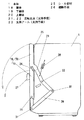
従来、この種の食器洗浄機には、特開平10−337225号公報に記載されているようなものがある。この装置は図6に示すような構成であり、食器等の被洗浄物を洗浄槽に収納し、本体1に設けた開口部2を扉体3により閉塞してから、洗浄ポンプが洗浄水を噴射することにより、被洗浄物の洗浄およびすすぎ工程を行うようになっていた。
【0003】
扉体3は、2個の扉体3aと3b同士を連結した2つ折れ構造となっており、外部への突出長さが小さく、扉体3の開閉に必要な空間を小さくできることから、水切り棚等が扉体3開閉の邪魔になず、開閉しやすいようになっていた。また、卓上設置型の場合には、装置の設置性が向上するようになっていた。
【0004】
【発明が解決しようとする課題】
しかしながら、従来の食器洗浄機では、扉体3は2つ折れ構造であり、1個の扉体3aは本体に直接回動支持されているが、他方の扉体3bは扉体3aに連結支持されていた。このため、扉体3aは、本体に対して一意的に移動せず、開閉操作は不安定となり、開閉しずらいという課題を有していた。また、一意的に動作させるためには、他の規制手段が別途必要とされていた。
【0005】
また、食器洗浄機では、洗浄用の噴流が扉体にも衝突するため、確実なシール構造を必要とするが、扉体の分割面の端部付近4のシールは、2つの扉体と本体との間の各々のシールと扉体同士の分割面のシールとの合計3箇所のシールを、閉塞過程において同時に行う必要があり、確実にシールすることは非常に困難であり、また確実に行なうためには、剛性を高めたり、形状が複雑化するなどという課題も有していた。
【0006】
【課題を解決するための手段】
本発明は上記課題を解決するために、本体と、前記本体内に設けた洗浄槽と、前記本体の前面で前記洗浄槽に設けた開口部と、前記開口部の上部及び下部をそれぞれ閉塞するとともに互いに分割している上及び下扉体とを備え、前記上及び下扉体を前記本体に対して移動自在に支持する支持手段を前記上及び下扉体に設け、前記上及び下扉体は、前記支持手段により前記開口部の下方向側へ開成する構成としたものである。
【0007】
上記発明によれば、下扉体と上扉体との複数個に分割した扉体を支持する支持手段は、各々の扉体を本体に対して移動自在に支持しており、各扉体は、移動する扉体ではなく、固定された本体に対して支持されていることから、安定した開閉操作を行うことができる。また、支持手段を、回動支点のように、本体に対して一意的に動作する構成とした場合には、より扉体開閉の操作性は向上する。また、支持手段は全ての扉体を開口部の下方向側へ開成する構成としたものであり、被洗浄物の出し入れ等の邪魔にならない方向に開成すれば、使い勝手を損なわない。また、本体の上方に空間を必要としないため、日本の狭い厨房空間においても設置できる可能性が高まる。また、扉体は分割されており、前方への突出長さは小さくなっていることから、より設置性は向上する。
さらに、開口部は本体の前面に設けられることにより、食器等を出し入れする際に、汁や水滴が洗浄機の外部に落下することを防止できる。また、前面を開口部とした場合は、上面に開口部がある場合と違って、わずかな水漏れであっても発生すれば装置外に漏れ出すため、より確実なシールが行える本発明の効果を十分に発揮できる。
【0008】
【発明の実施の形態】
本発明は、請求項1に記載のように、本体と、前記本体内に設けた洗浄槽と、前記本体の前面で前記洗浄槽に設けた開口部と、前記開口部の上部及び下部をそれぞれ閉塞するとともに互いに分割している上及び下扉体とを備え、前記上及び下扉体を前記本体に対して移動自在に支持する支持手段を前記上及び下扉体に設け、前記上及び下扉体は、前記支持手段により前記開口部の下方向側へ開成する構成としたものである。
【0009】
下扉体と上扉体との複数個に分割した扉体を支持する支持手段は、各々の扉体を本体に対して移動自在に支持しており、各扉体は、移動する扉体ではなく、固定された本体に対して支持されていることから、安定した開閉操作を行うことができる。また、支持手段を、回動支点のように、本体に対して一意的に動作する構成とした場合には、より扉体開閉の操作性は向上する。また、支持手段は全ての扉体を開口部の一方向側へ開成する構成としたものであり、被洗浄物の出し入れ等の邪魔にならない方向に開成すれば、使い勝手を損なわない。また、一方の扉体を閉塞後に他方の扉体を閉塞する構成とすれば、全てのシールを同時に行う必要はなく、容易に、かつ確実にシールを行うことができる。また、本体の上方に空間を必要としないため、日本の狭い厨房空間においても設置できる可能性が高まる。また、扉体は分割されており、前方への突出長さは小さくなっていることから、より設置性は向上する。
さらに、開口部は本体の前面に設けられることにより、食器等を出し入れする際に、汁や水滴が洗浄機の外部に落下することを防止できる。また、前面を開口部とした場合は、上面に開口部がある場合と違って、わずかな水漏れであっても発生すれば装置外に漏れ出すため、より確実なシールが行える本発明の効果を十分に発揮できる。
【0010】
また、請求項2の食器洗浄機は、全ての支持手段は、扉体を回動支持する構成としたものであり、扉体は本体に対して一意的に動作することから、より扉体の開閉操作性は向上する。また、扉体と本体とをスライドしない構成となることから、シール構造も容易となる。
【0012】
また、請求項3の食器洗浄機は、扉体の開成状態において扉体の最上面は、洗浄槽内に設けた洗浄かごの底部より下方に位置する構成としたものであり、扉体の開成状態で、洗浄かごを前方に引き出すことが可能となり、被洗浄物の出し入れを容易に行うことができる。
【0013】
また、請求項4の食器洗浄機は、扉体の開成状態における各扉体の先端位置は、略一致するように各扉体の長さを設定したものであり、開成位置における扉体の外部への突出長さを最小にでき、食器洗浄機の設置に必要な面積が小さくなることから、厨房等に設置できる可能性が高まる。
【0014】
また、請求項5の食器洗浄機は、支持手段は、本体の壁面内部に設置したものであり、扉体の閉塞状態では、支持手段は外側へ露出しないため、良好な外観が得られると共に、始動時に指を挟む等の危険を生じる恐れがない。また、開閉動作中も、本体に手を添えながら扉体を操作しても、指を挟む等の危険はない。
【0015】
また、請求項6の食器洗浄機は、本体と扉体とをシールするシール部材は、支持手段より内側に設けたものであり、洗浄中も支持手段は洗浄槽内とは完全にシールされた状態となることから、支持手段の耐久性が向上する。また、回動支点等の潤滑状態が保たれるため、開閉操作の安定性を維持できる。
【0016】
また、請求項7の食器洗浄機は、扉体の開閉動作を連動する連動手段を設けたものであり、1回の操作で全ての扉体を開閉させることが可能であり、装置の使い勝手が飛躍的に向上する。また、扉体同士間のシールを確実に行うためには、扉体の開閉順序を規定する必要があるが、連動手段を用いることで順序通りの開閉を確実に行うことができる。
【0017】
【実施例】
以下、本発明の実施例について図面を用いて説明する。
【0018】
(実施例1)
図1、図2は本発明の実施例1の食器洗浄機の側面図および断面図である。
【0019】
図において、本体1内に設けた洗浄槽5があり、食器等の被洗浄物6は洗浄かご7にセットされ、洗浄槽5内に収納されている。洗浄槽5に洗浄水を供給する給水弁8、洗浄水を加圧する洗浄ポンプ9があり、洗浄水を噴射する洗浄ノズル10には噴射孔11が複数個設けられている。また、洗浄槽5内には残菜を収集するフィルタ12と加熱用の発熱体13があり、洗浄槽の温度を検知する温度センサ14を備えている。また、洗浄水を排出する排水ポンプ14aと、洗浄槽5に空気を送る送風機15を備えており、送風機15により送風された空気を洗浄槽5に導く送風経路16を設け、その排気を排出する排気口17を扉体18に設けている。
【0020】
また、洗浄槽5の開口部2を閉塞する2個の扉体18(下扉体19と上扉体20)を設けており、各々の扉体19、20を本体1に対して移動自在に支持する支持手段として回転支点21、22および上扉体と一体化して設けた支持アーム23とを設置している。また、扉体18と本体1間をシールするシール部材24は本体1側に、扉体19、20同士の分割位置をシールするシール部材25は上扉体に設置しており、開放時には下扉体を先に開放し、閉塞時には上扉体を先に閉塞する構成としている。また、2個の扉体18の開閉動作を連動させる連動手段26を備えており、扉体18の開閉操作を行うハンドル部27は下扉体19に設け、扉体18を上方向に付勢する付勢手段として引っ張りバネ28を設けている。また、扉体の開成状態において扉体の最上面は、洗浄槽内に設けた洗浄かごの底部より下方に位置する構成としている。図示していないが、扉体18の閉塞位置で扉体19を係止するロック手段を備えている。
【0021】
次に動作、作用について説明するが、まず食器洗浄機の基本動作について説明すると、食器等の被洗浄物6を洗浄かご7にセットしてから洗浄槽5に収納し、洗剤を投入した後、扉体18により本体1の開口部2を閉塞し、装置の運転を開始する。被洗浄物6の汚れを落とす洗浄工程、付着した洗剤や残菜を流すすすぎ工程、そして被洗浄物6に付着している水適を乾燥させる乾燥工程の順に実行される。まず、給水弁8が動作して所定量の洗浄水を洗浄槽5に供給し、続いて洗浄ポンプ9が洗浄水を加圧し、洗浄ノズル10から噴射する。この際、洗浄槽5内に設けたシーズヒータ等の発熱体13に通電しており、洗浄水を加温しながら洗浄工程は行われる。また、温度センサ14は洗浄槽5の温度を検知しており、所定温度以上になると発熱体13への通電を停止するようになっている。
【0022】
所定時間の洗浄工程を終えると、汚れを含む洗浄水は排水ポンプ14aにより機外に排出され、新たに洗浄水が供給される。洗浄ポンプ9を運転し、洗浄ノズル10から再び洗浄水を噴射して、洗剤や残菜等の付着した被洗浄物6のすすぎを行う。所定時間運転した後、洗浄水を排出し、再び洗浄水を供給するという動作を繰り返し、このすすぎ工程は連続して3回程度行う。最後に、洗浄水を機外に排出して、すすぎ工程は終了する。
【0023】
続いて乾燥工程が行われ、送風機15を動作させることにより、送風経路16を通って外気が洗浄槽5内に送風され、排気口17から排出される。この際、発熱体13には通電されており、送風と温度の両方の効果によって被洗浄物6に付着した水滴の蒸発は促進される。所定時間これらの乾燥工程を行い、運転を終了する。
【0024】
次に、扉体18に関して説明すると、2個に分割した扉体19、20を支持する支持手段21、22は、各々の扉体19、20を本体1に対して回動自在に支持しており、本体1に対して支持されていることから、不意な扉体19、20の動きが発生する恐れはなく、安定した開閉操作を行うことができる。また、各扉体19、20は、回動状に一意的に動作するため、より安定した開閉操作を行うことができる。
【0025】
また、扉体19、20の開閉順序を定めた構成であり、上扉体20を閉塞後に下扉体19を閉塞する構成とすることで、まず上扉体20と本体1とのシールをシール部材25により確実に行い、続いて下扉体19の全周を本体1および上扉体20の下辺に設けたシール部材25および24によってシールするとで、容易に、かつ確実にシールすることができる。また、本体の前面を開口部2とした場合は、上面に開口部がある場合と違って、わずかな水漏れであっても発生すれば装置外に漏れ出すため、より確実なシールが行える本発明の効果を十分に発揮できる。
【0026】
また、扉体18は開口部の一方向のみに開放する構成であり、被洗浄物6の出し入れ等の邪魔にならない方向に開成すれば、扉体18によって使い勝手は損なわれない。本実施例の場合、扉体18を下方に開放することで、食器等を出し入れする際に、汁や水滴が洗浄機の外部に落下することも防止できる。また、上方に扉体は開成しないため、流し台等の天面に設置した場合でも、洗浄槽5内の確認の妨げにならない。
【0027】
なお、上方開放であっても、使用の妨げとならない構成であればよく、この場合は、下方に開放した扉体18が存在しないため、本体1の床面積程度の設置面積があれば、本装置を設置することができ、より設置性を高めることができる。また、上下方向以外の横方向に開成する構成であっても、同様の効果が得られる。
【0028】
また、図1では、卓上設置型としたが、開口部2は本体1の前面に設け、両扉体19、20ともに下方に開放することで、本体の上方に空間を必要としないことから、前面開放のビルトイン型の食器洗浄機の扉体構造に利用できる。また、卓上設置型の洗浄機に適用した場合でも、本体1の上方に空間を必要としないため、日本の狭い厨房空間においても設置できる可能性が高まる。また、扉体18は分割されており、前方への突出長さは小さくなっていることから、より設置性は向上する。特に、扉体18の開成状態で、各扉体19、20の先端位置が略一致するように各扉体19、20の長さを設定した場合には、開成位置における扉体18の外部への突出長さを最小にできるため、食器洗浄機の設置に必要な面積は最も小さくなる。また、設置面積が小さいことから、縦置き、横置き等の多くの設置バリエーションにも対応でき、各家庭の形態に適合することができる。
【0029】
また、図1のように、扉体19、20の開閉順序を定めてた構成としており、開成時には下扉体19の開成後に上扉体20を開成するもので、開閉順序に適応したシール部材24の設置構成となっており、シール部材24の損傷等を与えずに、かつ小さな操作力で確実にシールを行うことが可能である。
【0030】
また、図1では、上下の扉体19、20の開閉動作を連動する連動手段26を設けており、下扉体19に設けたハンドル部27を持って開放すれば、両方の扉体19、20が1つの動作で開閉ができる。これにより、装置の使い勝手が飛躍的に向上するとともに、扉体18の開閉順序を一意的に規制できることから、先に下扉体19が開くような構成としておけば、作業者は扉体18の開閉順序を考慮する必要がなくなる。なお、下扉体19が完全に先に開かなくとも、下扉体19の移動量が上扉体20の移動量よりも大きければよく、具体的には、図のように、下扉体19の回転支点21の反対側に延長した位置に設けた支点31と、支持アーム23を回転支点22の反対側に延長した位置に設けた支点32とを連動手段26で連結することで実現できる。
【0031】
なお、連動手段26の設置に限定するものではなく、連動手段26を用いない場合でも、先に開放する扉体にのみハンドル部27を設ける等の手段で、開閉順序を規定することができる。
【0032】
また、連動手段26はリンク構造としたため、開放時、閉塞時ともに連動動作を一意的に規制できるため、いかなる扉体の動作に対しても、確実に連動開閉動作が行える。また、上扉体20を動作させた場合でも、下扉体19は連動して動くことから、操作する扉体を問わない。なお、連動手段26はリンク構造に限定するものではなく、ワイヤで連結したり、歯車やベルト、チェーン等で連動させるなど、他の構成であっても同様の効果が得られる。
【0033】
また、図1に示した構成だと、連動手段26が本体1の外側にはみ出すことはなく、リンクの間に指を挟む等の危険を生じる恐れがなく、良好な外観が得られる。
【0034】
また、扉体18の開成状態において扉体18の最上面29は、洗浄槽5内に設けた洗浄かご7の底部30より下方に位置する構成としたものであり、図2のように扉体18の開成状態で、洗浄かご7を前方に引き出すことが可能となり、洗浄かごの7の奥に収納した被洗浄物7の出し入れも容易に行うことができる。この際、下方に扉体18が開放されていることから、洗浄かご7を引き出した時に、水滴等が装置の前方に落下することを防止できる。また、洗浄かご7に設けたローラー33等が、扉体20の上面をスライドする構成であれば、引き出した状態で洗浄かごを安定させることができ、被洗浄物6の出し入れも容易に行える。
【0035】
また、付勢手段として設けた引っ張りバネ28は、扉体18を上方へ付勢するため、扉体18の開閉操作力が小さくなり、操作性が向上する。また、扉体18が重力によって自由降下する際の衝撃力を低減でき、装置にかかる応力が小さくなることから、耐久性向上や装置の小型化につながる。また、閉塞位置近傍では扉体18は自然に閉塞し、開放位置近傍では扉体18は自然に開放する構成とすることで、より快適な操作性が得られる。なお、ねじりバネ等の他の弾性手段であっても同様の効果が得られる。
【0036】
また、図示していないが、扉体18の閉塞位置で扉体18を係止するロック手段を設けており、運転中に扉体18が開放したり、シールが不完全となり水漏れ等が発生することを防止する。まお、このロック手段は、扉体18と本体1と係止する構成であったり、扉体19と20同士を係止する構成であったり、あるいは連動手段26と本体1とを係止するなど、いかなる構成であっても効果が得られる。また、扉体18の閉塞動作と動時にロックされる構成であっても、閉塞動作とは別にレバー等を移動させる構成であってもよい。
【0037】
なお、図1、図2では、卓上設置型で前面に開口部2を有する食器洗浄機の例を示したが、これに限定するものではなく、ビルトイン型の食器洗浄機であっても同様の効果が得られる。また、従来と同じトップロード型で、図3に示したように上方に開口部2を有する構造であっても、扉体の開閉操作が一意的に行えることから、安定した開閉操作が行えるなど上記と同様の効果が得られる。また、本体1の水平断面の矩形形状における長辺を含む面を開口部2としたが、短辺側を開口部2とすることもできる。また、扉体18は2分割とし、上下方向に開閉する構成としたが、3個あるいはそれ以上に分割した構成も考えられる。また、上下方向以外にも、横方向に回動する構成であっても同様の効果が得られる。
【0038】
また、支持手段21、22は回動支点としたが、図4に示すようにスライド部34を有するなどの構成であってもよい。
【0039】
なお、本発明は扉体18の開閉構造に関するものであり、洗浄や乾燥の方式や構成、運転モード等を限定するものではない。実施例では、乾燥機能を有する食器洗い乾燥機の例を示したが、乾燥機能を伴わない食器洗浄機や乾燥のみを行なう食器乾燥機、あるいは収納装置等の他の機器にも、本発明の扉構造を利用できる。また、他の装置にも本扉構成なお、他の実施例についても同様である。
【0040】
(実施例2)
図5は本発明の実施例2の食器洗浄機の部分斜視図であり、図1に示した実施例1と同じ構成要素には同一の符号を付与している。
【0041】
図5に示すように、支持手段は本体の壁面35内部に設置しており、本体と扉体とをシールするシール部材25は支持手段より内側に設置している。
【0042】
次に動作、作用について説明すると、支持手段を本体の側壁35内部に収めることで、扉体18の閉塞状態では、回転支点22や支持アーム23等は外側へ露出しないため、良好な外観が得られると共に、始動時に指を挟む等の危険を生じる恐れがない。また、開閉動作中も、本体1に手を添えながら扉体18を操作しても、指を挟む等の危険はない。また、シール部材25は、支持手段である回転支点22や支持アーム23等より内側部分に設置することで、洗浄槽5内とは完全にシールされた状態となり、金属製であっても、錆や腐食を防止できるなど、耐久性が向上する。また、回動支点等の潤滑状態が保たれるため、開閉操作の安定性を維持できる。
【0043】
また、側壁35の強度を確保し、かつ幅を小型化するためには、本体から出入りする部材は薄い方がよく、図1のように、連動手段26が本体1の外側にはみ出さないような構成だと、本体1から出入りする部材は支持アーム23のみで済むことから、幅方向の小型化につながる。
【0044】
なお、実施例1では、分かりやすいように壁面の外側にある如くに図示したが、同様に本体の壁面35内部に収めることが可能である。
【0045】
【発明の効果】
以上のように本発明によれば、複数個の扉体を本体に対して移動自在に支持する支持手段を各々の扉体に対して設け、支持手段は全ての扉体を開口部の一方向側へ開成する構成としたものであり、扉体同士ではなく、固定された本体に対して各々の扉体は支持されていることから、安定した開閉操作を行うことができる。また、支持手段は全ての扉体を開口部の一方向側へ開成する構成としたものであり、被洗浄物の出し入れ等の邪魔にならない方向に開成すれば、使い勝手を損なわない。また、一方の扉体を閉塞後に他方の扉体を閉塞する構成とすれば、全てのシールを同時に行う必要はなく、容易に、かつ確実にシールを行うことができる。また、本体の上方に空間を必要としないため、日本の狭い厨房空間においても設置できる可能性が高まる。また、扉体は分割されており、前方への突出長さは小さくなっていることから、より設置性は向上する。
【図面の簡単な説明】
【図1】 本発明の実施例1の食器洗浄機の側面図
【図2】 同実施例1の食器洗浄機の断面図
【図3】 同実施例1における開口部を上面に設けた場合の食器洗浄機の概略図
【図4】 同実施例1における他の支持手段を用いた場合の食器洗浄機の側面図
【図5】 本発明の実施例2の食器洗浄機の扉体部分の断面図
【図6】 従来の食器洗浄機の側面図
【符号の説明】
1 本体
2 開口部
5 洗浄槽
18 扉体
19 下扉体
20 上扉体
21、22 回転支点(支持手段)
23 支持アーム(支持手段)
25 シール部材
26 連動部材
29 扉体開成時の最上面
30 洗浄かごの底部
35 壁面[0001]
BACKGROUND OF THE INVENTION
The present invention relates to a dishwasher and a dishwasher used in general households.
[0002]
[Prior art]
Conventionally, this type of dishwasher includes one described in JP-A-10-337225. This apparatus is configured as shown in FIG. 6, and the object to be cleaned such as tableware is stored in the cleaning tank, and the
[0003]
Since the
[0004]
[Problems to be solved by the invention]
However, in the conventional dishwasher, the
[0005]
Moreover, in the dishwasher, since the cleaning jet also collides with the door body, a reliable sealing structure is required. However, the seal in the vicinity of the end portion 4 of the split surface of the door body includes the two door bodies and the main body. It is necessary to perform a total of three seals including a seal on each of the doors and a seal on the split surface of the doors simultaneously in the closing process, and it is very difficult to perform the seal reliably and is performed reliably. For this purpose, there have been problems such as increased rigidity and complicated shapes.
[0006]
[Means for Solving the Problems]
In order to solve the above problems, the present invention closes the main body , the cleaning tank provided in the main body, the opening provided in the cleaning tank on the front surface of the main body, and the upper and lower parts of the opening. and a upper and lower door body are separated from each other with, provided a support means for supporting the upper and lower door body movably relative to the body on said and lower door body, before SL on and lower door The body is configured to open to the lower side of the opening by the support means.
[0007]
According to the above invention, the support means for supporting the door body divided into a plurality of lower door bodies and upper door bodies supports each door body movably with respect to the main body, and each door body is Since it is supported not on the moving door body but on the fixed main body, a stable opening / closing operation can be performed. Further, when the support means is configured to operate uniquely with respect to the main body, such as a rotation fulcrum, the operability for opening and closing the door body is further improved. Further, the support means is configured to open all the doors downward in the opening portion, and if it is opened in a direction that does not interfere with the removal and insertion of the object to be cleaned, the usability is not impaired. In addition, since no space is required above the main body, the possibility of installation in a small kitchen space in Japan increases. Moreover, since the door body is divided | segmented and the protrusion length ahead is small, installation property improves more.
Furthermore, the opening is provided on the front surface of the main body, so that it is possible to prevent the juice and water droplets from dropping outside the washing machine when taking out and taking in tableware and the like. In addition, when the front surface is an opening, unlike the case where there is an opening on the upper surface, even if a slight water leak occurs, it leaks out of the device, so the effect of the present invention that can provide a more reliable seal Can be fully demonstrated.
[0008]
DETAILED DESCRIPTION OF THE INVENTION
According to the present invention, as described in
[0009]
The support means for supporting the door body divided into a plurality of lower door bodies and upper door bodies supports each door body movably with respect to the main body, and each door body is a moving door body. Since it is supported with respect to the fixed main body, a stable opening / closing operation can be performed. Further, when the support means is configured to operate uniquely with respect to the main body, such as a rotation fulcrum, the operability for opening and closing the door body is further improved. Further, the support means is configured to open all the door bodies in one direction of the opening, and the usability is not impaired if it is opened in a direction that does not interfere with the removal and insertion of the object to be cleaned. Further, if one door is closed, then the other door is closed, it is not necessary to perform all the sealing simultaneously, and the sealing can be performed easily and reliably. In addition, since no space is required above the main body, the possibility of installation in a small kitchen space in Japan increases. Moreover, since the door body is divided | segmented and the protrusion length ahead is small, installation property improves more.
Furthermore, the opening is provided on the front surface of the main body, so that it is possible to prevent the juice and water droplets from dropping outside the washing machine when taking out and taking in tableware and the like. In addition, when the front surface is an opening, unlike the case where there is an opening on the upper surface, even if a slight water leak occurs, it leaks out of the device, so the effect of the present invention that can provide a more reliable seal Can be fully demonstrated.
[0010]
Further, in the dishwasher according to
[0012]
The dishwasher according to
[0013]
Moreover, the dishwasher of Claim 4 sets the length of each door body so that the front-end | tip position of each door body in the open state of a door body may correspond substantially, The exterior of the door body in an open position Since the protrusion length to the wall can be minimized and the area required for installing the dishwasher is reduced, the possibility of being installed in a kitchen or the like is increased.
[0014]
In the dishwasher of claim 5 , the support means is installed inside the wall surface of the main body, and in the closed state of the door body, the support means is not exposed to the outside, so that a good appearance is obtained, There is no risk of pinching your fingers when starting. Further, even during the opening / closing operation, there is no danger of pinching a finger even if the door body is operated while putting a hand on the main body.
[0015]
Further, in the dishwasher according to claim 6 , the sealing member for sealing the main body and the door body is provided inside the support means, and the support means is completely sealed from the inside of the washing tank even during cleaning. Since it will be in a state, durability of a support means will improve. Further, since the lubrication state such as the rotation fulcrum is maintained, the stability of the opening / closing operation can be maintained.
[0016]
The dishwasher according to claim 7 is provided with interlocking means for interlocking opening and closing operations of the door body, and can open and close all the door bodies by one operation, and the usability of the apparatus is improved. Improve dramatically. Moreover, in order to perform the sealing between door bodies reliably, it is necessary to prescribe | regulate the opening-and-closing order of a door body, but it can perform opening and closing in order according to an interlocking means.
[0017]
【Example】
Embodiments of the present invention will be described below with reference to the drawings.
[0018]
Example 1
1 and 2 are a side view and a sectional view of the dishwasher according to the first embodiment of the present invention.
[0019]
In the figure, there is a cleaning tank 5 provided in the
[0020]
Further, two door bodies 18 (a
[0021]
Next, the operation and action will be described. First, the basic operation of the dishwasher will be described. After the object 6 to be cleaned such as tableware is set in the cleaning basket 7, it is stored in the cleaning tank 5, and the detergent is introduced. The
[0022]
When the cleaning process for a predetermined time is finished, the cleaning water containing dirt is discharged out of the apparatus by the
[0023]
Subsequently, a drying process is performed, and by operating the
[0024]
Next, the
[0025]
Moreover, it is the structure which defined the opening-and-closing order of the
[0026]
Further, the
[0027]
In addition, even if it is upwardly open, any configuration that does not hinder use is sufficient. In this case, since there is no
[0028]
Further, in FIG. 1, a desktop installation type is provided, but the
[0029]
Further, as shown in FIG. 1, the opening / closing order of the
[0030]
In FIG. 1, interlocking means 26 for interlocking the opening and closing operations of the upper and
[0031]
In addition, it is not limited to installation of the interlocking means 26, and even when the interlocking means 26 is not used, the opening / closing order can be defined by means such as providing the
[0032]
Further, since the interlocking
[0033]
Further, with the configuration shown in FIG. 1, the interlocking means 26 does not protrude outside the
[0034]
Further, the
[0035]
Further, since the
[0036]
Although not shown, a lock means for locking the
[0037]
In addition, in FIG. 1, FIG. 2, although the example of the dishwasher which has the
[0038]
Moreover, although the support means 21 and 22 were the rotation fulcrum, as shown in FIG. 4, the structure of having the
[0039]
Note that the present invention relates to the opening / closing structure of the
[0040]
(Example 2)
FIG. 5 is a partial perspective view of the dishwasher according to the second embodiment of the present invention. The same components as those in the first embodiment shown in FIG.
[0041]
As shown in FIG. 5, the support means is installed inside the
[0042]
Next, the operation and action will be described. By placing the support means inside the
[0043]
Further, in order to ensure the strength of the
[0044]
In the first embodiment, for the sake of easy understanding, it is shown as being outside the wall surface, but it can be similarly housed inside the
[0045]
【The invention's effect】
As described above, according to the present invention, the support means for movably supporting the plurality of door bodies with respect to the main body is provided for each door body, and the support means has all the door bodies in one direction of the opening. Since each door body is supported with respect to the fixed main body instead of the door bodies, a stable opening / closing operation can be performed. Further, the support means is configured to open all the door bodies in one direction of the opening, and the usability is not impaired if it is opened in a direction that does not interfere with the removal and insertion of the object to be cleaned. Further, if one door is closed, then the other door is closed, it is not necessary to perform all the sealing simultaneously, and the sealing can be performed easily and reliably . In addition, since no space is required above the main body, the possibility of installation in a small kitchen space in Japan increases. Moreover, since the door body is divided | segmented and the protrusion length ahead is small, installation property improves more.
[Brief description of the drawings]
FIG. 1 is a side view of a dishwasher according to a first embodiment of the present invention. FIG. 2 is a cross-sectional view of the dishwasher according to the first embodiment. FIG. 4 is a schematic view of a dishwasher. FIG. 4 is a side view of the dishwasher when other support means is used in the first embodiment. FIG. 5 is a cross-sectional view of the door body portion of the dishwasher according to the second embodiment of the present invention. [Fig. 6] Side view of a conventional dishwasher [Explanation of symbols]
DESCRIPTION OF
23 Support arm (support means)
25
Claims (7)
Priority Applications (5)
| Application Number | Priority Date | Filing Date | Title |
|---|---|---|---|
| JP2000194202A JP4552282B2 (en) | 2000-06-28 | 2000-06-28 | Dishwasher |
| KR1020010028019A KR100567506B1 (en) | 2000-05-23 | 2001-05-22 | Dish washer |
| CNB011233982A CN100441135C (en) | 2000-05-23 | 2001-05-22 | Tableware washer |
| CN01228502U CN2505024Y (en) | 2000-05-23 | 2001-05-22 | Tableware-washing machine |
| TW090112293A TW555542B (en) | 2000-05-23 | 2001-05-23 | Tableware washing machine |
Applications Claiming Priority (1)
| Application Number | Priority Date | Filing Date | Title |
|---|---|---|---|
| JP2000194202A JP4552282B2 (en) | 2000-06-28 | 2000-06-28 | Dishwasher |
Publications (2)
| Publication Number | Publication Date |
|---|---|
| JP2002010961A JP2002010961A (en) | 2002-01-15 |
| JP4552282B2 true JP4552282B2 (en) | 2010-09-29 |
Family
ID=18693068
Family Applications (1)
| Application Number | Title | Priority Date | Filing Date |
|---|---|---|---|
| JP2000194202A Expired - Lifetime JP4552282B2 (en) | 2000-05-23 | 2000-06-28 | Dishwasher |
Country Status (1)
| Country | Link |
|---|---|
| JP (1) | JP4552282B2 (en) |
Families Citing this family (4)
| Publication number | Priority date | Publication date | Assignee | Title |
|---|---|---|---|---|
| JP4544344B2 (en) * | 2008-05-19 | 2010-09-15 | パナソニック株式会社 | dishwasher |
| JP5012755B2 (en) * | 2008-10-16 | 2012-08-29 | パナソニック株式会社 | dishwasher |
| WO2019045210A1 (en) * | 2017-08-31 | 2019-03-07 | 삼성전자주식회사 | Dishwasher and home appliances |
| KR102491589B1 (en) | 2017-08-31 | 2023-01-26 | 삼성전자주식회사 | Dish washing machine and home appliance |
-
2000
- 2000-06-28 JP JP2000194202A patent/JP4552282B2/en not_active Expired - Lifetime
Also Published As
| Publication number | Publication date |
|---|---|
| JP2002010961A (en) | 2002-01-15 |
Similar Documents
| Publication | Publication Date | Title |
|---|---|---|
| US9888828B2 (en) | Dishwasher with pivoting handle | |
| KR102002419B1 (en) | Dish washer | |
| JP4552282B2 (en) | Dishwasher | |
| KR100892672B1 (en) | Dispenser for dish washer | |
| JP4388086B2 (en) | Dishwasher | |
| JP3546809B2 (en) | Dishwasher | |
| JP3494117B2 (en) | Dishwasher | |
| JP2006263174A (en) | Dish washer and door open/close detecting device | |
| JP2008119205A (en) | Dishwasher | |
| JP2004049443A (en) | Dishwasher | |
| JP2006255277A (en) | Dishwasher | |
| JP2007301066A (en) | Dishwasher | |
| KR20070078131A (en) | Door openning and closing apparatus of dish washer | |
| JP3494179B2 (en) | Dishwasher | |
| JP3988739B2 (en) | dishwasher | |
| JP2004000790A (en) | Dish washer | |
| JP3654298B2 (en) | Dishwasher | |
| JP4042709B2 (en) | dishwasher | |
| JP4327664B2 (en) | Dishwasher | |
| KR101369321B1 (en) | Dishwasher | |
| JP7117600B2 (en) | dishwasher | |
| KR101127987B1 (en) | Apparatus for prevention splash in dish washer | |
| JP2620141B2 (en) | Dishwasher | |
| JP2004081889A (en) | Dishwasher | |
| JP5881674B2 (en) | dishwasher |
Legal Events
| Date | Code | Title | Description |
|---|---|---|---|
| A621 | Written request for application examination |
Free format text: JAPANESE INTERMEDIATE CODE: A621 Effective date: 20070402 |
|
| RD01 | Notification of change of attorney |
Free format text: JAPANESE INTERMEDIATE CODE: A7421 Effective date: 20070514 |
|
| A977 | Report on retrieval |
Free format text: JAPANESE INTERMEDIATE CODE: A971007 Effective date: 20090724 |
|
| A131 | Notification of reasons for refusal |
Free format text: JAPANESE INTERMEDIATE CODE: A131 Effective date: 20090804 |
|
| A521 | Written amendment |
Free format text: JAPANESE INTERMEDIATE CODE: A523 Effective date: 20090930 |
|
| RD01 | Notification of change of attorney |
Free format text: JAPANESE INTERMEDIATE CODE: A7421 Effective date: 20091119 |
|
| A131 | Notification of reasons for refusal |
Free format text: JAPANESE INTERMEDIATE CODE: A131 Effective date: 20100330 |
|
| A521 | Written amendment |
Free format text: JAPANESE INTERMEDIATE CODE: A523 Effective date: 20100528 |
|
| TRDD | Decision of grant or rejection written | ||
| A01 | Written decision to grant a patent or to grant a registration (utility model) |
Free format text: JAPANESE INTERMEDIATE CODE: A01 Effective date: 20100622 |
|
| A01 | Written decision to grant a patent or to grant a registration (utility model) |
Free format text: JAPANESE INTERMEDIATE CODE: A01 |
|
| A61 | First payment of annual fees (during grant procedure) |
Free format text: JAPANESE INTERMEDIATE CODE: A61 Effective date: 20100705 |
|
| FPAY | Renewal fee payment (event date is renewal date of database) |
Free format text: PAYMENT UNTIL: 20130723 Year of fee payment: 3 |
|
| R151 | Written notification of patent or utility model registration |
Ref document number: 4552282 Country of ref document: JP Free format text: JAPANESE INTERMEDIATE CODE: R151 |
|
| FPAY | Renewal fee payment (event date is renewal date of database) |
Free format text: PAYMENT UNTIL: 20130723 Year of fee payment: 3 |
|
| EXPY | Cancellation because of completion of term |