JP4551893B2 - Robot toy - Google Patents
Robot toy Download PDFInfo
- Publication number
- JP4551893B2 JP4551893B2 JP2006352818A JP2006352818A JP4551893B2 JP 4551893 B2 JP4551893 B2 JP 4551893B2 JP 2006352818 A JP2006352818 A JP 2006352818A JP 2006352818 A JP2006352818 A JP 2006352818A JP 4551893 B2 JP4551893 B2 JP 4551893B2
- Authority
- JP
- Japan
- Prior art keywords
- block
- servo
- output shaft
- robot toy
- gear
- Prior art date
- Legal status (The legal status is an assumption and is not a legal conclusion. Google has not performed a legal analysis and makes no representation as to the accuracy of the status listed.)
- Expired - Fee Related
Links
Images


Classifications
-
- A—HUMAN NECESSITIES
- A63—SPORTS; GAMES; AMUSEMENTS
- A63H—TOYS, e.g. TOPS, DOLLS, HOOPS OR BUILDING BLOCKS
- A63H29/00—Drive mechanisms for toys in general
- A63H29/24—Details or accessories for drive mechanisms, e.g. means for winding-up or starting toy engines
-
- A—HUMAN NECESSITIES
- A63—SPORTS; GAMES; AMUSEMENTS
- A63H—TOYS, e.g. TOPS, DOLLS, HOOPS OR BUILDING BLOCKS
- A63H11/00—Self-movable toy figures
- A63H11/18—Figure toys which perform a realistic walking motion
-
- A—HUMAN NECESSITIES
- A63—SPORTS; GAMES; AMUSEMENTS
- A63H—TOYS, e.g. TOPS, DOLLS, HOOPS OR BUILDING BLOCKS
- A63H3/00—Dolls
- A63H3/36—Details; Accessories
- A63H3/46—Connections for limbs
-
- B—PERFORMING OPERATIONS; TRANSPORTING
- B25—HAND TOOLS; PORTABLE POWER-DRIVEN TOOLS; MANIPULATORS
- B25J—MANIPULATORS; CHAMBERS PROVIDED WITH MANIPULATION DEVICES
- B25J17/00—Joints
-
- B—PERFORMING OPERATIONS; TRANSPORTING
- B25—HAND TOOLS; PORTABLE POWER-DRIVEN TOOLS; MANIPULATORS
- B25J—MANIPULATORS; CHAMBERS PROVIDED WITH MANIPULATION DEVICES
- B25J9/00—Programme-controlled manipulators
- B25J9/08—Programme-controlled manipulators characterised by modular constructions
-
- A—HUMAN NECESSITIES
- A63—SPORTS; GAMES; AMUSEMENTS
- A63H—TOYS, e.g. TOPS, DOLLS, HOOPS OR BUILDING BLOCKS
- A63H2200/00—Computerized interactive toys, e.g. dolls
-
- A—HUMAN NECESSITIES
- A63—SPORTS; GAMES; AMUSEMENTS
- A63H—TOYS, e.g. TOPS, DOLLS, HOOPS OR BUILDING BLOCKS
- A63H30/00—Remote-control arrangements specially adapted for toys, e.g. for toy vehicles
- A63H30/02—Electrical arrangements
- A63H30/04—Electrical arrangements using wireless transmission
-
- Y—GENERAL TAGGING OF NEW TECHNOLOGICAL DEVELOPMENTS; GENERAL TAGGING OF CROSS-SECTIONAL TECHNOLOGIES SPANNING OVER SEVERAL SECTIONS OF THE IPC; TECHNICAL SUBJECTS COVERED BY FORMER USPC CROSS-REFERENCE ART COLLECTIONS [XRACs] AND DIGESTS
- Y10—TECHNICAL SUBJECTS COVERED BY FORMER USPC
- Y10T—TECHNICAL SUBJECTS COVERED BY FORMER US CLASSIFICATION
- Y10T29/00—Metal working
- Y10T29/53—Means to assemble or disassemble
- Y10T29/53978—Means to assemble or disassemble including means to relatively position plural work parts
Description
本発明は、ロボット玩具に関し、さらに詳しくは、サーボを備えたロボット玩具に係わる。 The present invention relates to a robot toy , and more particularly to a robot toy equipped with a servo.
従来、一のブロックと他のブロックとをサーボを介して連結した構造のロボット玩具が知られている。このロボット玩具においては、次のようにしてロボット玩具を組み立てるのが一般的であった。
まず、人型のロボット玩具の足について説明する。ここで、足の構成要素として、RCターボが取り付けられた一のブロックと、この一のブロックに連結すべき他のブロックとを含むものとする。この場合、まず、サーボの信号線に初期パルスを与えて中心位置(サーボ・ゼロ位置)を出しておき、一のブロックと他のブロックの関節部を伸ばした位置(メカニカル・ゼロ位置)で、サーボの出力軸に他方のブロックに形成された軸孔を嵌合する。このようにして、隣接するブロックを組み付けてゆく。これによって、足全体を組み立てる。
また、足と同様にして手の構成要素同士、胴部と頭部、胴部と手足を連結する。
なお、「メカニカル・ゼロ位置」とはロボット玩具が基本姿勢を取る場合の各構成要素の位置を言う。2足歩行のロボット玩具の場合には直立姿勢が基本姿勢となるのが一般である(例えば、非特許文献1)。
First, the legs of a humanoid robot toy will be described. Here, as a leg component, one block to which the RC turbo is attached and another block to be connected to the one block are included. In this case, first give an initial pulse to the servo signal line to give the center position (servo zero position), and at the position where the joint part of one block and the other block is extended (mechanical zero position), A shaft hole formed in the other block is fitted to the output shaft of the servo. In this way, adjacent blocks are assembled. This assembles the entire foot.
In addition, the components of the hand, the torso and head, and the torso and limbs are connected in the same manner as the foot.
The “mechanical zero position” refers to the position of each component when the robot toy takes the basic posture. In the case of a biped walking robot toy, the upright posture is generally the basic posture (for example, Non-Patent Document 1).
ところが、ロボット玩具のメカニカル・ゼロ位置と基本始動位置(ホームポジション)とが異なっていることも多い。例えば、2足歩行のロボット玩具について言えば、直立姿勢位置がメカニカル・ゼロ位置であり、腰を少し落とした位置がホームポジションである。この2足歩行のロボット玩具の場合、腰を少し落とした位置(ホームポジション)から左右の脚を交互に前方に出して歩行するのが自然である。
しかし、上述のように、サーボ・ゼロ位置はメカニカル・ゼロ位置に合致しているため、サーボの信号線に初期パルスを与えると、ロボット玩具の足はまず直立姿勢位置を取る。そして、その後に、ロボット玩具は腰を少し落とし、その後に左右の足を交互に前方に出して歩行することとなる。
このようなロボット玩具の動作は不自然である。
そこで、サーボ・ゼロ位置を基本始動位置に合致させる必要がある。例えば、2足歩行のロボット玩具の場合には、サーボの信号線に初期パルスを与えたときに、直ちに、ロボット玩具が腰を少し落とした姿勢位置(基本始動位置;ホームポジション)となるように調整する必要がある。
そのため、従来、ロボット玩具内の制御用ICをパソコンに繋いで、エディタによって、初期パルスのパルス幅を変更することで、サーボ・ゼロ位置とホームポジションとを合致させていた。
しかし、その作業は煩雑である。
このような事態は、ロボット玩具の構成要素に設計誤差がある場合などにも生じる。
また、このようなロボット玩具においては、サーボモータの軸が回転中に出力軸が何らかの原因により強制的に停止させられた際に、出力軸への動力伝達を遮断する必要がある。
However, the mechanical zero position and the basic starting position (home position) of the robot toy are often different. For example, for a biped robot toy, the upright position is the mechanical zero position, and the position where the waist is slightly dropped is the home position. In the case of this biped robot toy, it is natural to walk with the left and right legs alternately coming forward from a position where the waist is slightly lowered (home position).
However, since the servo zero position coincides with the mechanical zero position as described above, when an initial pulse is applied to the servo signal line, the robot toy foot first takes an upright posture position. After that, the robot toy falls a little and then walks with the left and right feet alternately forward.
The operation of such a robot toy is unnatural.
Therefore, it is necessary to make the servo zero position coincide with the basic starting position. For example, in the case of a robot toy walking on two legs, when an initial pulse is applied to the servo signal line, the robot toy immediately assumes a posture position (basic starting position; home position) where the waist is slightly lowered. It needs to be adjusted.
Therefore, conventionally, the servo zero position and the home position are matched by connecting the control IC in the robot toy to the personal computer and changing the pulse width of the initial pulse by an editor.
However, the work is complicated.
Such a situation also occurs when there are design errors in the components of the robot toy.
Further, in such a robot toy, when the output shaft is forcibly stopped for some reason while the servo motor shaft is rotating, it is necessary to cut off the power transmission to the output shaft.
本発明は、かかる問題点を解決するためになされたもので、ロボット玩具においては、サーボモータの軸が回転中に出力軸が何らかの原因により強制的に停止させられた際に、出力軸への動力伝達を遮断するクラッチ機構を備えるロボット玩具を提供することを目的としている。 The present invention has been made to solve such a problem, and in a robot toy, when the output shaft is forcibly stopped for some reason while the shaft of the servo motor is rotating, it is applied to the output shaft. An object of the present invention is to provide a robot toy including a clutch mechanism that cuts off power transmission .
請求項1記載のロボット玩具は、ケースに収納されたサーボモータ、減速歯車機構及びロータリーエンコーダから構成されるサーボを手足の関節部分に組み込んだロボット玩具において、
前記減速歯車機構の最終段の歯車と該歯車の軸心と合致した軸心を持つ前記サーボの出力軸とは独立して回転できるように構>成され、
前記最終段の歯車と前記出力軸との間にはクラッチ機構が組み込まれ、
前記クラッチ機構は、
前記最終段の歯車の端面の軸から離間した部分に該軸を挟んで対向するよう立設され外側面が湾曲した半円柱状の2つの突起と、
環状を呈し内周に前記半円柱状の2つの突起と係合する2つの凹部と該2つの凹部同士を結ぶ線と直交する方向で対向し前記出力軸に付設された歯車の歯に噛み合う2つの凸部とが形成された弾性変形可能なクラッチ部材とを備える、
ことを特徴とする。
The robot toy according to
The final stage gear of the reduction gear mechanism and the output shaft of the servo having an axis coincident with the axis of the gear are configured to be able to rotate independently,
A clutch mechanism is incorporated between the final stage gear and the output shaft,
The clutch mechanism is
Two semi-cylindrical protrusions that are erected so as to oppose each other with the shaft sandwiched between the end surface of the gear of the final stage, and the outer surface is curved;
2 meshing with gear teeth that are attached to opposite in direction said output shaft perpendicular to the line connecting the two recesses and the two recesses each other to engage the two protrusions of the semi-cylindrical circumferentially in an annular shape An elastically deformable clutch member formed with two convex portions,
It is characterized by that.
本発明によれば、ロボット玩具において、サーボモータの軸が回転中に出力軸が何らかの原因により強制的に停止させられた際に、出力軸への動力伝達を遮断することができる。 According to the present invention, in the robot toy, power transmission to the output shaft can be interrupted when the output shaft is forcibly stopped for some reason while the shaft of the servo motor is rotating.
図1はロボット本体の正面図、図2はロボット本体の右側面図である。
ロボット玩具1は、図示しないコントローラの操作によって遠隔で動作制御されるものである。具体的には、このロボット玩具1は、コントローラの操作によって、ロボット玩具1の手足の動作が制御されるように構成されている。
FIG. 1 is a front view of the robot body, and FIG. 2 is a right side view of the robot body.
The
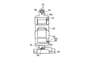
このロボット玩具1の手足の関節部分には、図3に示すようなサーボ3が組み込まれている。このサーボ3は、ケース30に収納されたサーボモータ31、減速歯車機構32およびロータリーエンコーダ33によって構成されている。減速歯車機構32は、歯車32a〜32jを含んで構成されている。
そして、この減速歯車機構32の最終段の歯車32jと出力軸34との間にはクラッチ機構35が組み込まれている。
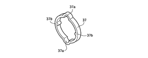
すなわち、歯車32jと出力軸34とは互いに独立して回転できるように構成されている。このうち、歯車32jの端面には、図4に示すように、2つの半円柱状の突起32j−a,32j−aが付設されている。この2つの突起32j−a,32j−aは歯車32jの軸を挟んで対向するよう設けられている。一方、出力軸34の端面には、図5に示すように、歯車36が付設されている。そして、歯車32jと歯車35とは図6に示すクラッチ部材37を介して連結されている。クラッチ部材37は環状を呈しており、その内周には、2つの半円柱状の突起32j−a,32j−aに係合する2つの凹部37a,37aと、歯車36の歯に噛み合う2つの凸部37b,37bとが形成されている。2つの凸部37b,37bは、2つの凹部37a,37aを結ぶ線と直交する方向で対向している。そして、サーボモータ31の軸が回転中に出力軸34が何らかの原因により強制的に停止させられた際に、クラッチ部材37が弾性変形して歯車32jから歯車36ひいては出力軸34への動力伝達を遮断する。
A
A
That is, the
また、ロボット玩具1の胴部には、電池(図示せず)と、処理装置100および受信回路110が組み込まれている(図7参照)。処理装置100は、受信回路110、サーボモータ3に接続されている。処理装置100は、内部の記憶装置に記憶されたプログラムに従って、受信回路110およびサーボ3からの信号等を処理し、サーボモータ31の動作の制御を行う。例えば、ロボット玩具1の電源が投入された場合、初期パルスをサーボモータ31に与え、サーボ3を中心位置(サーボ・ゼロ位置)に移行させる。
Moreover, the battery (not shown), the
続いて、このロボット玩具1の外観構成について説明すれば、このロボット玩具1は、胴部10、頭部11、足部12及び手部13を備えている。そして、ロボット玩具1の関節部にはサーボ3がそれぞれ組み込まれている。
Then, if the external structure of this
ここで、足部12の構造について説明すれば、このロボット玩具1の足部12は、図8(正面図)および図9(右側面図)に示すように、大別して、5つのブロック21,22,23,24,25から構成されている。
Here, the structure of the
このうち、ブロック21は胴部(ブロック)10に連結されている。すなわち、胴部10にはサーボ3a(他のサーボと区別するために符号3aを用いる)が組み込まれている。そして、ブロック21は、サーボ3aの出力軸34に嵌合し、これによって、ブロック21は胴部10に連結されている。したがって、サーボ3aのサーボモータ31を回転駆動した際に、胴部10に対してブロック21が動作することになる。
Among these, the
この場合のブロック21と胴部10との連結構造について詳細に説明すれば、ブロック21の連結部には、図10に示すように、軸孔50aに達するすり割り(スリット)50bが形成されている。このすり割り50bの隙間はねじ50cによって調整できるように構成されている。そして、ねじ50cの締結具合によるすり割り50bの隙間調整によって軸孔50aの径を変更できるように構成されている。この場合のねじ50cは、隙間調整部材ひいては軸孔径調整部材を構成する。軸孔径調整部材としては、単なるねじの他、クランプ、又は、すり割り50bを挟んで対峙する部分を外方から挟み込むクリップなどが考えられる。以下、同様である。
具体的には、ねじ50cを緩めた場合には、軸孔50aは出力軸34にゆるく嵌った状態(遊嵌状態)となる。この状態では、出力軸34はブロック21と一体化せず、出力軸34は軸孔50a内で空転可能となる。一方、ねじ50cを締め付けた場合には、軸孔50aは出力軸34にきつく嵌った状態(嵌合状態)となる。この状態では、出力軸34はブロック21と一体化し、出力軸34が回転するとブロック21も出力軸34を中心に回転することとなる。
The connecting structure between the
Specifically, when the
また、ブロック21にはブロック22が連結されている。すなわち、ブロック21にはサーボ3b(他のサーボと区別するために符号3bを用いる)が組み込まれている。そして、ブロック22の連結部の軸孔は、サーボ3bの出力軸34に嵌合し、これによって、ブロック22はブロック21に連結されている。したがって、サーボ3bのサーボモータ31を回転駆動した際に、ブロック21に対してブロック22が動作することになる。
この場合の出力軸34とブロック22との連結構造は、胴部10に組み込まれたサーボ3bの出力軸34とブロック21との連結構造と同じである。すなわち、ブロック22の連結部にはすり割り50bが形成され、すり割り50bの隙間はねじによって調整可能となっている。そして、すり割り50bの隙間調整によって、ブロック22の軸孔50aの径がサーボ3bの出力軸34に対して遊嵌状態と嵌合状態との間で変化するように構成されている。
A
In this case, the connection structure between the
また、ブロック22にはブロック23が連結されている。すなわち、ブロック23にはサーボ3c(他のサーボと区別するために符号3cを用いる)が組み込まれている。そして、ブロック22は、サーボ3cの出力軸34に嵌合し、これによって、ブロック22にブロック23が連結されている。したがって、サーボ3cのサーボモータ31が回転駆動した際に、ブロック22に対してブロック23が動作することになる。
この場合の出力軸34とブロック22との連結構造は、胴部10に組み込まれたサーボ3cの出力軸34とブロック21との連結構造と同じである。すなわち、ブロック22の連結部にはすり割り50bが形成され、すり割り50bの隙間はねじによって調整可能となっている。そして、すり割り50bの隙間調整によって、ブロック22の軸孔50aの径がサーボ3cの出力軸34に対して遊嵌状態と嵌合状態との間で変化するように構成されている。
A
In this case, the connection structure between the
また、ブロック23にはブロック24が連結されている。すなわち、ブロック23にはサーボ3d(他のサーボと区別するために符号3dを用いる)が組み込まれている。そして、ブロック24は、サーボ3dの出力軸34に嵌合し、これによって、ブロック23にブロック24が連結されている。したがって、サーボ3dのサーボモータ31を回転駆動した際に、ブロック23に対してブロック24が動作することになる。
この場合の出力軸34とブロック24との連結構造は、胴部10に組み込まれたサーボ3dの出力軸34とブロック21との連結構造と同じである。すなわち、ブロック24の連結部にはすり割り50bが形成され、すり割り50bの隙間はねじによって調整可能となっている。そして、すり割り50bの隙間調整によって、ブロック24の軸孔50aの径がサーボ3dの出力軸34に対して遊嵌状態と嵌合状態との間で変化するように構成されている。
The
In this case, the connection structure between the
また、ブロック24にはブロック25が連結されている。すなわち、ブロック24にはサーボ3e(他のサーボと区別するために符号3dを用いる)が組み込まれている。そして、ブロック25は、サーボ3eの出力軸34に嵌合し、これによって、ブロック24にブロック25が連結されている。したがって、サーボ3eのサーボモータ31を回転駆動した際に、ブロック24に対してブロック25が動作することになる。
この場合の出力軸34とブロック25との連結構造は、胴部10に組み込まれたサーボ3eの出力軸34とブロック21との連結構造と同じである。すなわち、ブロック25の連結部にはすり割り50bが形成され、すり割り50bの隙間はねじによって調整可能となっている。そして、すり割り50bの隙間調整によって、ブロック25の軸孔50aの径がサーボ3eの出力軸34に対して遊嵌状態と嵌合状態との間で変化するように構成されている。
The
In this case, the connection structure between the
続いて、手部13の構造について説明すれば、手部13は、図11(正面図)および図12(右側面図)に示すように、大別して、4つのブロック41,42,43,44,45から構成されている。そして、ブロック41,42,43,44,45はこの順に連結されている。この場合の隣り合うブロック同士の連結構造は足部12の隣り合うブロック同士の連結構造と同じとなっている。なお、胴部(ブロック)10とブロック41の連結構造は手部13のブロック同士の連結構造と同じであっても良いし、胴部10にブロック41が固定されていても良い。
Next, the structure of the
次に、ロボット玩具1の組立方法について足部12を例にして説明する。
例えば、胴部10とブロック21とを連結する場合、ねじ50cを緩め、ブロック21の軸孔50aを、胴部10に組み込まれたサーボ3の出力軸34に遊嵌させる。この状態では、出力軸34はブロック21と一体化せず、出力軸34は軸孔50a内で空転可能である。この状態で、胴部10とブロック21との角度を位置調整治具を使って調整する。具体的には、胴部10とブロック21との角度をホームポジションに合わせる。そして、この状態を保ったままで、サーボ3に通電し、サーボ3の中心位置(サーボ・ゼロ位置)を出した後に、ねじ50cを締め付ける。これによって、サーボ・ゼロ位置と、胴部10とブロック21とのホームポジションとを合わせることができる。
Next, a method for assembling the
For example, when connecting the trunk | drum 10 and the
以上と同様にして、足部12の隣り合うブロック同士を連結するとともに、手部13の隣り合うブロック同士を連結する。
In the same manner as described above, adjacent blocks of the
以上、本発明の実施形態について説明したが、本発明は、かかる実施形態に限定されるものではなく、その要旨を逸脱しない範囲で種々の変形が可能であることは言うまでもない。
例えば、上記実施形態では、ブロックを1つずつ順番に連結する場合について説明したが、例えば、足部12の構成ブロック全体を緩く連結しておいた状態(サーボ3の軸34と軸孔50aが遊嵌した状態)で、ロボット玩具1の電源をリセットボタンを押しながらONした後、サーボ3を中心位置にした状態で、位置調整治具によって足部12における隣接するブロック同士の位置関係をロボット玩具1自体のホームポジションに合致させ、隙間調整部材によって出力軸34と軸孔50aとを嵌合状態とするようにしても良い。
この場合に使用される位置調整治具60の一例が図12に示されている。同図において、符号60aはサーボ3の出力軸34に対応する位置を示す指標であり、この指標60aにサーボ3の出力軸34を合致させれば自動的にブロック同士の位置関係をロボット玩具1自体のホームポジションに合致させることができるようになっている。
なお、位置調整治具は、嵌込み式になっていて、ロボット玩具1をセットすれば、自動的にブロック同士の位置関係をロボット玩具1自体のホームポジションに合致させることができるようになっていても良い。
As mentioned above, although embodiment of this invention was described, it cannot be overemphasized that this invention is not limited to this embodiment, A various deformation | transformation is possible in the range which does not deviate from the summary.
For example, in the above-described embodiment, the case where the blocks are sequentially connected one by one has been described. However, for example, the entire constituent block of the
An example of the
The position adjustment jig is a fitting type, and if the
1 ロボット玩具
3,3a〜3e サーボ
10 胴部
11 頭部
12 足部
13 手部
21〜25 ブロック
31 サーボモータ
34 出力軸
41〜44 ブロック
50a 軸孔
50b すり割り
50c ねじ(隙間調整治具)
60 位置調整治具
DESCRIPTION OF
60 Position adjustment jig
Claims (1)
前記減速歯車機構の最終段の歯車と該歯車の軸心と合致した軸心を持つ前記サーボの出力軸とは独立して回転できるように構成され、
前記最終段の歯車と前記出力軸との間にはクラッチ機構が組み込まれ、
前記クラッチ機構は、
前記最終段の歯車の端面の軸から離間した部分に該軸を挟んで対向するよう立設され外側面が湾曲した半円柱状の2つの突起と、
環状を呈し内周に前記半円柱状の2つの突起と係合する2つの凹部と該2つの凹部同士を結ぶ線と直交する方向で対向し前記出力軸に付設された歯車の歯に噛み合う2つの凸部とが形成された弾性変形可能なクラッチ部材とを備える、
ことを特徴とするロボット玩具。 In a robot toy in which a servo composed of a servo motor, a reduction gear mechanism and a rotary encoder housed in a case is incorporated in a joint part of a limb,
The final stage gear of the reduction gear mechanism and the output shaft of the servo having an axis coincident with the axis of the gear are configured to be able to rotate independently.
A clutch mechanism is incorporated between the final stage gear and the output shaft,
The clutch mechanism is
Two semi-cylindrical protrusions that are erected so as to oppose each other with the shaft sandwiched between the end surface of the gear of the final stage, and the outer surface is curved;
2 meshing with gear teeth that are attached to opposite in direction said output shaft perpendicular to the line connecting the two recesses and the two recesses each other to engage the two protrusions of the semi-cylindrical circumferentially in an annular shape An elastically deformable clutch member formed with two convex portions,
A robot toy characterized by that.
Priority Applications (7)
| Application Number | Priority Date | Filing Date | Title |
|---|---|---|---|
| JP2006352818A JP4551893B2 (en) | 2006-12-27 | 2006-12-27 | Robot toy |
| US11/822,300 US7862398B2 (en) | 2006-12-27 | 2007-07-03 | Robot toy |
| EP10156604A EP2196248B1 (en) | 2006-12-27 | 2007-12-05 | Robot toy and assembling method thereof |
| DE602007007718T DE602007007718D1 (en) | 2006-12-27 | 2007-12-05 | Toy robot and assembly method for it |
| EP07122348A EP1938877B1 (en) | 2006-12-27 | 2007-12-05 | Robot toy and assembling method thereof |
| KR1020070128782A KR20080061277A (en) | 2006-12-27 | 2007-12-12 | Robot toy and assembling method thereof |
| CNA2007101608654A CN101209383A (en) | 2006-12-27 | 2007-12-27 | Robot toy and assembling method thereof |
Applications Claiming Priority (1)
| Application Number | Priority Date | Filing Date | Title |
|---|---|---|---|
| JP2006352818A JP4551893B2 (en) | 2006-12-27 | 2006-12-27 | Robot toy |
Publications (2)
| Publication Number | Publication Date |
|---|---|
| JP2008161350A JP2008161350A (en) | 2008-07-17 |
| JP4551893B2 true JP4551893B2 (en) | 2010-09-29 |
Family
ID=39292819
Family Applications (1)
| Application Number | Title | Priority Date | Filing Date |
|---|---|---|---|
| JP2006352818A Expired - Fee Related JP4551893B2 (en) | 2006-12-27 | 2006-12-27 | Robot toy |
Country Status (6)
| Country | Link |
|---|---|
| US (1) | US7862398B2 (en) |
| EP (2) | EP1938877B1 (en) |
| JP (1) | JP4551893B2 (en) |
| KR (1) | KR20080061277A (en) |
| CN (1) | CN101209383A (en) |
| DE (1) | DE602007007718D1 (en) |
Families Citing this family (20)
| Publication number | Priority date | Publication date | Assignee | Title |
|---|---|---|---|---|
| JP4551893B2 (en) | 2006-12-27 | 2010-09-29 | 株式会社タカラトミー | Robot toy |
| JP4397412B2 (en) | 2007-12-07 | 2010-01-13 | 株式会社タカラトミー | Robot toy and its assembly method |
| AU2012359758A1 (en) * | 2012-01-31 | 2013-09-19 | Tomy Company, Ltd. | Robot toy |
| CN103252093B (en) * | 2012-06-21 | 2015-04-29 | 上海未来伙伴机器人有限公司 | Steering engine component |
| US10695686B2 (en) * | 2013-09-27 | 2020-06-30 | Innovation First, Inc. | Mechanical spinning robot toy |
| ES2752126T3 (en) * | 2014-03-31 | 2020-04-03 | Artec Co Ltd | Mounting block with servo motor, and mounting block kit |
| US10081098B1 (en) | 2014-08-25 | 2018-09-25 | Boston Dynamics, Inc. | Generalized coordinate surrogates for integrated estimation and control |
| US9387588B1 (en) | 2014-08-25 | 2016-07-12 | Google Inc. | Handling gait disturbances with asynchronous timing |
| US9618937B1 (en) | 2014-08-25 | 2017-04-11 | Google Inc. | Slip detection using robotic limbs |
| US9446518B1 (en) * | 2014-11-11 | 2016-09-20 | Google Inc. | Leg collision avoidance in a robotic device |
| US9499218B1 (en) | 2014-12-30 | 2016-11-22 | Google Inc. | Mechanically-timed footsteps for a robotic device |
| US9594377B1 (en) * | 2015-05-12 | 2017-03-14 | Google Inc. | Auto-height swing adjustment |
| US10331105B2 (en) * | 2015-08-07 | 2019-06-25 | Spm Automation (Canada) Inc. | Machine for self-adjusting its operation to compensate for part-to-part variations |
| US9586316B1 (en) | 2015-09-15 | 2017-03-07 | Google Inc. | Determination of robotic step path |
| US9789919B1 (en) | 2016-03-22 | 2017-10-17 | Google Inc. | Mitigating sensor noise in legged robots |
| USD835214S1 (en) * | 2017-06-13 | 2018-12-04 | Ubtech Education (Shenzhen) Co., Ltd | Robot |
| USD832373S1 (en) * | 2017-10-06 | 2018-10-30 | Kma Concepts Limited | Posable toy gorilla |
| CN107791242A (en) * | 2017-11-23 | 2018-03-13 | 深圳市优必选科技有限公司 | Steering wheel and robot |
| KR20210143461A (en) * | 2020-05-20 | 2021-11-29 | 로보티즈 인코포레이티드 | Small actuator for robot |
| CN117018639A (en) * | 2023-08-18 | 2023-11-10 | 蔡泽銮 | Assembling robot toy |
Citations (5)
| Publication number | Priority date | Publication date | Assignee | Title |
|---|---|---|---|---|
| JPS6443996U (en) * | 1987-09-14 | 1989-03-16 | ||
| JP2002059388A (en) * | 2000-08-23 | 2002-02-26 | Sony Corp | Rotary actuator and walking robot with rotary actuator |
| JP2003136461A (en) * | 2001-10-31 | 2003-05-14 | Omron Corp | Joint part structure of robot |
| JP2004209250A (en) * | 2003-01-03 | 2004-07-29 | Megarobotics Co Ltd | Artificial intelligence type robot toy and control method thereof |
| JP2006035405A (en) * | 2004-07-30 | 2006-02-09 | Sanko Gosei Ltd | Joint device for robot |
Family Cites Families (22)
| Publication number | Priority date | Publication date | Assignee | Title |
|---|---|---|---|---|
| US3547240A (en) * | 1968-09-19 | 1970-12-15 | Frank Holper | Clutch means for selectively coupling a single input to one or more plural outputs |
| US5155423A (en) * | 1986-02-18 | 1992-10-13 | Robotics Research Corporation | Industrial robot with servo |
| JP2602815B2 (en) * | 1986-08-08 | 1997-04-23 | 株式会社東芝 | Joint device |
| JPH0377754A (en) | 1989-08-18 | 1991-04-03 | Kawasaki Steel Corp | Method for preventing drift stream of molten steel poured into continuous casting mold |
| US5280981A (en) * | 1991-02-01 | 1994-01-25 | Odetics, Inc. | End effector with load-sensitive digit actuation mechanisms |
| US5158493A (en) * | 1991-05-30 | 1992-10-27 | Richard Morgrey | Remote controlled, multi-legged, walking robot |
| US5318471A (en) * | 1991-12-06 | 1994-06-07 | Glovier Lloyd H | Robotic joint movement device |
| JPH09193059A (en) | 1996-01-17 | 1997-07-29 | Canon Inc | Origin position calibrating method of robot, its origin position calibrating device, calibrating jig and arm positioning device of robot |
| US5823845A (en) * | 1996-03-12 | 1998-10-20 | Kieran Bergin, Inc. | Mobile, gyroscopically stabilized toy with controlled multi-action movements |
| US6032548A (en) * | 1997-08-08 | 2000-03-07 | Del Castillo; Leonardo | System and method for creating movement utilizing a servo mechanism with a self-aligning clutch |
| US6481512B1 (en) * | 1999-01-28 | 2002-11-19 | Sony Corporation | Joint device for robot device and leg- walking robot device |
| US6902048B1 (en) * | 1999-04-14 | 2005-06-07 | Caleb Chung | Clutch |
| KR100532685B1 (en) | 2000-11-17 | 2005-12-01 | 혼다 기켄 고교 가부시키가이샤 | Legged robot |
| US6454624B1 (en) * | 2001-08-24 | 2002-09-24 | Xerox Corporation | Robotic toy with posable joints |
| JP3558220B2 (en) * | 2002-03-18 | 2004-08-25 | ソニー株式会社 | Hand device and robot device used for robot device |
| US6989645B2 (en) * | 2002-12-18 | 2006-01-24 | Sony Corporation | Robot apparatus, and load absorbing apparatus and method |
| JP2004255475A (en) | 2003-02-24 | 2004-09-16 | Oki Electric Ind Co Ltd | Servo apparatus |
| JP4299567B2 (en) | 2003-03-31 | 2009-07-22 | 本田技研工業株式会社 | Legged mobile robot |
| JP4305323B2 (en) * | 2004-08-11 | 2009-07-29 | ソニー株式会社 | Robot apparatus motion control device and motion control method |
| JP4506512B2 (en) | 2005-03-07 | 2010-07-21 | トヨタ自動車株式会社 | Offset adjustment system and offset adjustment method for walking robot with supporting legs |
| JP4254804B2 (en) * | 2006-05-15 | 2009-04-15 | 双葉電子工業株式会社 | Coupling mechanism of connecting member for robot and walking robot |
| JP4551893B2 (en) | 2006-12-27 | 2010-09-29 | 株式会社タカラトミー | Robot toy |
-
2006
- 2006-12-27 JP JP2006352818A patent/JP4551893B2/en not_active Expired - Fee Related
-
2007
- 2007-07-03 US US11/822,300 patent/US7862398B2/en not_active Expired - Fee Related
- 2007-12-05 DE DE602007007718T patent/DE602007007718D1/en active Active
- 2007-12-05 EP EP07122348A patent/EP1938877B1/en not_active Expired - Fee Related
- 2007-12-05 EP EP10156604A patent/EP2196248B1/en not_active Expired - Fee Related
- 2007-12-12 KR KR1020070128782A patent/KR20080061277A/en not_active Application Discontinuation
- 2007-12-27 CN CNA2007101608654A patent/CN101209383A/en active Pending
Patent Citations (5)
| Publication number | Priority date | Publication date | Assignee | Title |
|---|---|---|---|---|
| JPS6443996U (en) * | 1987-09-14 | 1989-03-16 | ||
| JP2002059388A (en) * | 2000-08-23 | 2002-02-26 | Sony Corp | Rotary actuator and walking robot with rotary actuator |
| JP2003136461A (en) * | 2001-10-31 | 2003-05-14 | Omron Corp | Joint part structure of robot |
| JP2004209250A (en) * | 2003-01-03 | 2004-07-29 | Megarobotics Co Ltd | Artificial intelligence type robot toy and control method thereof |
| JP2006035405A (en) * | 2004-07-30 | 2006-02-09 | Sanko Gosei Ltd | Joint device for robot |
Also Published As
| Publication number | Publication date |
|---|---|
| EP2196248A3 (en) | 2011-03-16 |
| KR20080061277A (en) | 2008-07-02 |
| EP2196248A2 (en) | 2010-06-16 |
| US7862398B2 (en) | 2011-01-04 |
| EP1938877A1 (en) | 2008-07-02 |
| JP2008161350A (en) | 2008-07-17 |
| CN101209383A (en) | 2008-07-02 |
| EP2196248B1 (en) | 2012-04-04 |
| DE602007007718D1 (en) | 2010-08-26 |
| EP1938877B1 (en) | 2010-07-14 |
| US20080160873A1 (en) | 2008-07-03 |
Similar Documents
| Publication | Publication Date | Title |
|---|---|---|
| JP4551893B2 (en) | Robot toy | |
| JP4397412B2 (en) | Robot toy and its assembly method | |
| JP4254804B2 (en) | Coupling mechanism of connecting member for robot and walking robot | |
| US7429844B2 (en) | Servo unit and joint servo for use in a robot system | |
| JP3545995B2 (en) | Robot joint structure | |
| KR20110080922A (en) | Robot hand and robot having the same | |
| KR100639900B1 (en) | Joint device for robot device and leg-walking robot device | |
| WO2001062448A1 (en) | Unit set for robot | |
| JP2007160482A (en) | Neck part joint mechanism and robot provided with the same | |
| JPH1128629A (en) | Gear assembly device | |
| JP5478387B2 (en) | Robot link device | |
| KR101749572B1 (en) | Structure of robot joint and robot having the same | |
| JP2002254259A (en) | Tool for two-shaft concurrent fastening | |
| JP2005131733A (en) | Link for walking type robot | |
| JP2000280195A (en) | Joint device, leg type traveling device and arm device for robot device, leg type traveling robot device, and driving force transmitting device | |
| KR20120043887A (en) | Joint module of universal robot | |
| JP5125841B2 (en) | Key fitting | |
| JPH0932819A (en) | Member assembling and adjusting device | |
| JP6875364B2 (en) | Gear mechanism, gear adjustment method and robot | |
| JPH045192Y2 (en) | ||
| JPS6119590A (en) | Wrist device for robot | |
| JP2007243710A (en) | Antenna supporting structure | |
| KR20110034065A (en) | Method for manufacturing of frame using sticker | |
| KR20180092607A (en) | Multi joint robot | |
| JP2006102898A (en) | Robot device |
Legal Events
| Date | Code | Title | Description |
|---|---|---|---|
| A621 | Written request for application examination |
Free format text: JAPANESE INTERMEDIATE CODE: A621 Effective date: 20080818 |
|
| A521 | Request for written amendment filed |
Free format text: JAPANESE INTERMEDIATE CODE: A523 Effective date: 20081105 |
|
| A521 | Request for written amendment filed |
Free format text: JAPANESE INTERMEDIATE CODE: A821 Effective date: 20081105 |
|
| A131 | Notification of reasons for refusal |
Free format text: JAPANESE INTERMEDIATE CODE: A131 Effective date: 20090127 |
|
| A521 | Request for written amendment filed |
Free format text: JAPANESE INTERMEDIATE CODE: A523 Effective date: 20090330 |
|
| A131 | Notification of reasons for refusal |
Free format text: JAPANESE INTERMEDIATE CODE: A131 Effective date: 20090825 |
|
| A521 | Request for written amendment filed |
Free format text: JAPANESE INTERMEDIATE CODE: A523 Effective date: 20091026 |
|
| TRDD | Decision of grant or rejection written | ||
| A01 | Written decision to grant a patent or to grant a registration (utility model) |
Free format text: JAPANESE INTERMEDIATE CODE: A01 Effective date: 20100629 |
|
| A01 | Written decision to grant a patent or to grant a registration (utility model) |
Free format text: JAPANESE INTERMEDIATE CODE: A01 |
|
| A61 | First payment of annual fees (during grant procedure) |
Free format text: JAPANESE INTERMEDIATE CODE: A61 Effective date: 20100712 |
|
| R150 | Certificate of patent or registration of utility model |
Ref document number: 4551893 Country of ref document: JP Free format text: JAPANESE INTERMEDIATE CODE: R150 Free format text: JAPANESE INTERMEDIATE CODE: R150 |
|
| FPAY | Renewal fee payment (event date is renewal date of database) |
Free format text: PAYMENT UNTIL: 20130716 Year of fee payment: 3 |
|
| R250 | Receipt of annual fees |
Free format text: JAPANESE INTERMEDIATE CODE: R250 |
|
| R250 | Receipt of annual fees |
Free format text: JAPANESE INTERMEDIATE CODE: R250 |
|
| R250 | Receipt of annual fees |
Free format text: JAPANESE INTERMEDIATE CODE: R250 |
|
| R250 | Receipt of annual fees |
Free format text: JAPANESE INTERMEDIATE CODE: R250 |
|
| R250 | Receipt of annual fees |
Free format text: JAPANESE INTERMEDIATE CODE: R250 |
|
| R250 | Receipt of annual fees |
Free format text: JAPANESE INTERMEDIATE CODE: R250 |
|
| R250 | Receipt of annual fees |
Free format text: JAPANESE INTERMEDIATE CODE: R250 |
|
| LAPS | Cancellation because of no payment of annual fees |