JP4551685B2 - Information processing apparatus and information processing apparatus control method - Google Patents
Information processing apparatus and information processing apparatus control method Download PDFInfo
- Publication number
- JP4551685B2 JP4551685B2 JP2004108044A JP2004108044A JP4551685B2 JP 4551685 B2 JP4551685 B2 JP 4551685B2 JP 2004108044 A JP2004108044 A JP 2004108044A JP 2004108044 A JP2004108044 A JP 2004108044A JP 4551685 B2 JP4551685 B2 JP 4551685B2
- Authority
- JP
- Japan
- Prior art keywords
- fuel cell
- program
- information processing
- processing apparatus
- unit
- Prior art date
- Legal status (The legal status is an assumption and is not a legal conclusion. Google has not performed a legal analysis and makes no representation as to the accuracy of the status listed.)
- Expired - Fee Related
Links
Images


Classifications
-
- H—ELECTRICITY
- H01—ELECTRIC ELEMENTS
- H01M—PROCESSES OR MEANS, e.g. BATTERIES, FOR THE DIRECT CONVERSION OF CHEMICAL ENERGY INTO ELECTRICAL ENERGY
- H01M8/00—Fuel cells; Manufacture thereof
- H01M8/04—Auxiliary arrangements, e.g. for control of pressure or for circulation of fluids
- H01M8/04298—Processes for controlling fuel cells or fuel cell systems
- H01M8/04992—Processes for controlling fuel cells or fuel cell systems characterised by the implementation of mathematical or computational algorithms, e.g. feedback control loops, fuzzy logic, neural networks or artificial intelligence
-
- H—ELECTRICITY
- H01—ELECTRIC ELEMENTS
- H01M—PROCESSES OR MEANS, e.g. BATTERIES, FOR THE DIRECT CONVERSION OF CHEMICAL ENERGY INTO ELECTRICAL ENERGY
- H01M8/00—Fuel cells; Manufacture thereof
- H01M8/04—Auxiliary arrangements, e.g. for control of pressure or for circulation of fluids
- H01M8/04298—Processes for controlling fuel cells or fuel cell systems
- H01M8/04313—Processes for controlling fuel cells or fuel cell systems characterised by the detection or assessment of variables; characterised by the detection or assessment of failure or abnormal function
- H01M8/0444—Concentration; Density
- H01M8/04447—Concentration; Density of anode reactants at the inlet or inside the fuel cell
-
- H—ELECTRICITY
- H01—ELECTRIC ELEMENTS
- H01M—PROCESSES OR MEANS, e.g. BATTERIES, FOR THE DIRECT CONVERSION OF CHEMICAL ENERGY INTO ELECTRICAL ENERGY
- H01M8/00—Fuel cells; Manufacture thereof
- H01M8/04—Auxiliary arrangements, e.g. for control of pressure or for circulation of fluids
- H01M8/04298—Processes for controlling fuel cells or fuel cell systems
- H01M8/04694—Processes for controlling fuel cells or fuel cell systems characterised by variables to be controlled
- H01M8/04791—Concentration; Density
- H01M8/04798—Concentration; Density of fuel cell reactants
-
- H—ELECTRICITY
- H01—ELECTRIC ELEMENTS
- H01M—PROCESSES OR MEANS, e.g. BATTERIES, FOR THE DIRECT CONVERSION OF CHEMICAL ENERGY INTO ELECTRICAL ENERGY
- H01M8/00—Fuel cells; Manufacture thereof
- H01M8/04—Auxiliary arrangements, e.g. for control of pressure or for circulation of fluids
- H01M8/04298—Processes for controlling fuel cells or fuel cell systems
- H01M8/04694—Processes for controlling fuel cells or fuel cell systems characterised by variables to be controlled
- H01M8/04955—Shut-off or shut-down of fuel cells
-
- Y—GENERAL TAGGING OF NEW TECHNOLOGICAL DEVELOPMENTS; GENERAL TAGGING OF CROSS-SECTIONAL TECHNOLOGIES SPANNING OVER SEVERAL SECTIONS OF THE IPC; TECHNICAL SUBJECTS COVERED BY FORMER USPC CROSS-REFERENCE ART COLLECTIONS [XRACs] AND DIGESTS
- Y02—TECHNOLOGIES OR APPLICATIONS FOR MITIGATION OR ADAPTATION AGAINST CLIMATE CHANGE
- Y02E—REDUCTION OF GREENHOUSE GAS [GHG] EMISSIONS, RELATED TO ENERGY GENERATION, TRANSMISSION OR DISTRIBUTION
- Y02E60/00—Enabling technologies; Technologies with a potential or indirect contribution to GHG emissions mitigation
- Y02E60/30—Hydrogen technology
- Y02E60/50—Fuel cells
Landscapes
- Engineering & Computer Science (AREA)
- Life Sciences & Earth Sciences (AREA)
- Manufacturing & Machinery (AREA)
- Sustainable Development (AREA)
- Sustainable Energy (AREA)
- Chemical & Material Sciences (AREA)
- Chemical Kinetics & Catalysis (AREA)
- Electrochemistry (AREA)
- General Chemical & Material Sciences (AREA)
- Artificial Intelligence (AREA)
- Health & Medical Sciences (AREA)
- Automation & Control Theory (AREA)
- Computing Systems (AREA)
- Evolutionary Computation (AREA)
- Fuzzy Systems (AREA)
- Medical Informatics (AREA)
- Software Systems (AREA)
- Theoretical Computer Science (AREA)
- Fuel Cell (AREA)
- Power Sources (AREA)
Description
本発明は、情報処理装置および情報処理装置の制御方法に係り、特に、燃料電池ユニットを備えた情報処理装置および燃料電池ユニットの制御プログラムを更新する情報処理装置の制御方法に関する。 The present invention relates to an information processing apparatus and an information processing apparatus control method, and more particularly, to an information processing apparatus including a fuel cell unit and an information processing apparatus control method for updating a fuel cell unit control program.
現在、情報処理装置への電源供給源の一つである二次電池として例えばリチウムイオン電池が使用されている。二次電池の有する特徴の一つは、使い捨てタイプである一次電池と比較して、例えば商用電源を用いて充電することで繰り返し使用可能な点にある。 Currently, for example, a lithium ion battery is used as a secondary battery which is one of the power supply sources to the information processing apparatus. One of the characteristics of a secondary battery is that it can be used repeatedly by charging it with a commercial power source, for example, as compared with a disposable primary battery.
一方で、リチウムイオン電池は二次電池であるため、例えば商用電源を用いて充電する必要である。 On the other hand, since a lithium ion battery is a secondary battery, it needs to be charged using, for example, a commercial power source.
また、近年における情報処理装置の機能性能の向上は著しく、これに伴って情報処理装置の消費電力は増加の傾向にある。そこで、情報処理装置に電力を供給するリチウムイオン電池が提供するエネルギの密度、即ち単位体積或いは単位質量あたりの出力エネルギ量の向上が図られているものの、顕著な向上を望むのは難しい状況にある。 In recent years, the functional performance of information processing apparatuses has been remarkably improved, and the power consumption of information processing apparatuses has been increasing accordingly. Therefore, although the energy density provided by the lithium ion battery that supplies power to the information processing apparatus, that is, the amount of output energy per unit volume or unit mass has been improved, it is difficult to expect a significant improvement. is there.
一方、燃料電池のエネルギ密度は、理論的にはリチウムイオン電池の10倍とも言われている(例えば、非特許文献1参照)。これは、燃料電池がリチウムイオン電池に対して、体積或いは質量が同じとすると、より長時間(例えば10倍)の電力供給が可能となる潜在的能力を有していることを意味する。また、両者の電力供給時間を等しいとするならば、燃料電池の方がリチウムイオン電池に対して小型・軽量化が可能となる潜在的能力を有している事を意味する。 On the other hand, the energy density of a fuel cell is theoretically said to be 10 times that of a lithium ion battery (see Non-Patent Document 1, for example). This means that if the fuel cell has the same volume or mass as the lithium ion battery, it has the potential to supply power for a longer time (for example, 10 times). Further, if the power supply times of both are equal, it means that the fuel cell has the potential to be smaller and lighter than the lithium ion battery.
また、燃料電池は、燃料、例えばメタノール等を小型の容器に封入してユニット化し、小型の容器ごと交換して使用すれば、外部からの充電を必要としない。従って、例えばAC電源設備の無い場所において、リチウムイオン電池を使用して電力を確保する場合と比較して燃料電池を使用して電力を確保する場合の方が、より長時間にわたって情報処理装置を使用可能である。 Further, the fuel cell does not require charging from the outside if the fuel cell, for example, methanol, is enclosed in a small container to form a unit and the small container is replaced and used. Therefore, for example, in a place where there is no AC power supply facility, the information processing apparatus is used for a longer time when the power is secured using the fuel cell than when the power is secured using the lithium ion battery. It can be used.
さらに、リチウムイオン電池を使用した情報処理装置(例えばノート型パーソナルコンピュータ)を長時間使用する場合、リチウムイオン電池の供給する電力を用いて長時間使用することは困難であるため、AC電源による電力供給が可能な環境で情報処理装置を使用しなければならないという制約が課せられる。しかしながら、燃料電池の供給する電力で情報処理装置を使用するとリチウムイオン電池を用いる場合と比較して長時間に渡る情報処理装置の使用が可能になるとともに、上述の制約から解放されることが期待できる。 Furthermore, when an information processing device using a lithium ion battery (for example, a notebook personal computer) is used for a long time, it is difficult to use the power supplied by the lithium ion battery for a long time. There is a restriction that the information processing apparatus must be used in an environment where supply is possible. However, when an information processing device is used with the power supplied by the fuel cell, it is possible to use the information processing device for a long time compared to the case of using a lithium ion battery, and it is expected to be freed from the above-mentioned restrictions. it can.
以上のような観点から、情報処理装置への電力供給を目的とした燃料電池の研究・開発が進められており、これまでにも、例えば特許文献1,特許文献2に開示されている。
From the above viewpoint, research and development of a fuel cell for the purpose of supplying power to the information processing apparatus has been advanced, and so far, for example, disclosed in Patent Document 1 and
燃料電池の方式には種々のものがあるが(例えば非特許文献2参照)、情報処理装置に適するものとして、小型・軽量化、さらに燃料の取り扱いやすさといった観点を考慮すると、ダイレクトメタノール型燃料電池(DMFC:Direct Methanol Fuel Cell)方式が挙げられる。この方式の燃料電池は、燃料としてメタノールを用いるものであり、メタノールを水素に変換することなく直接、燃料極に注入する方式である。 There are various types of fuel cells (see, for example, Non-Patent Document 2), but considering that they are suitable for information processing apparatuses, direct methanol type fuel is considered in view of miniaturization, weight reduction, and ease of fuel handling. Examples thereof include a battery (DMFC: Direct Methanol Fuel Cell) system. This type of fuel cell uses methanol as the fuel, and is a method in which methanol is directly injected into the fuel electrode without being converted to hydrogen.
ダイレクトメタノール型燃料電池においては、燃料極に注入するメタノールの濃度が重要であり、この濃度が高いと発電効率が悪くなり十分な性能が得られない。これは燃料となるメタノールの一部が燃料極(負極)と空気極(正極)とに挟まれる電解質膜(固体高分子電解質膜)を透過してしまう現象(これをクロスオーバ現象と呼んでいる。)に起因するものである。クロスオーバ現象はメタノールの濃度が高濃度の場合に顕著になり、低濃度のメタノールを燃料極に注入した場合は低減される。 In the direct methanol fuel cell, the concentration of methanol injected into the fuel electrode is important. If this concentration is high, the power generation efficiency deteriorates and sufficient performance cannot be obtained. This is a phenomenon in which a part of methanol as fuel passes through an electrolyte membrane (solid polymer electrolyte membrane) sandwiched between a fuel electrode (negative electrode) and an air electrode (positive electrode) (this is called a crossover phenomenon). )). The crossover phenomenon becomes remarkable when the concentration of methanol is high, and is reduced when low concentration of methanol is injected into the fuel electrode.
一方、低濃度のメタノールを燃料として使用した場合、高性能を確保し易いものの、高濃度メタノールに比べると燃料の容積が大きくなるため(例えば10倍)、燃料の収納容器(燃料カートリッジ)が大型となってしまう。 On the other hand, when low-concentration methanol is used as a fuel, high performance is easy to ensure, but the volume of fuel is larger than that of high-concentration methanol (for example, 10 times), so the fuel container (fuel cartridge) is large. End up.
そこで、燃料カートリッジ内には高濃度のメタノールを収納することによって小型化をはかりつつ、一方で、発電時に発生する水を小型のポンプやバルブ等で循環させて高濃度メタノールを燃料極に注入する前に希釈することによってメタノールの濃度を下げ、その結果クロスオーバ現象を低減させることができる。この方式によって発電効率を向上させることが可能となる。なお、以降、循環させるためのポンプやバルブ等を補機と呼び、また、このように循環させる方式を希釈循環システムと呼ぶ。 Therefore, while miniaturization is achieved by storing high-concentration methanol in the fuel cartridge, the high-concentration methanol is injected into the fuel electrode by circulating water generated during power generation with a small pump or valve. By diluting in advance, the concentration of methanol can be lowered and, as a result, the crossover phenomenon can be reduced. This method makes it possible to improve the power generation efficiency. Hereinafter, a pump, a valve and the like for circulation are referred to as an auxiliary machine, and such a circulation system is referred to as a dilution circulation system.
このように、燃料電池ユニット全体としては小型軽量化を図りつつ、希釈されたメタノールによって、発電効率の高い燃料電池ユニットが実現できる(非特許文献1)。
燃料電池ユニットを備えた情報処理装置は、特に携帯型の情報処理装置であって商用電源の供給を受けない態様での動作においては、二次電池を電源とする場合に比べてより長時間の動作が可能となる。 An information processing apparatus provided with a fuel cell unit is a portable information processing apparatus, and in operation in a mode in which commercial power is not supplied, it takes a longer time than when a secondary battery is used as a power source. Operation is possible.
しかしながら、燃料電池ユニットを備えた情報処理装置では燃料電池ユニット固有の制御が必要となってくる。例えば、所定の発電効率を得るためには、燃料電池に注入される燃料の量や濃度、或いは空気(酸素)の量を、複数の補機の駆動によって適切に制御する必要がある。 However, the information processing apparatus provided with the fuel cell unit requires control specific to the fuel cell unit. For example, in order to obtain a predetermined power generation efficiency, it is necessary to appropriately control the amount and concentration of fuel injected into the fuel cell or the amount of air (oxygen) by driving a plurality of auxiliary machines.
また、燃料電池ユニットの情報、例えば燃料電池ユニットの識別情報、燃料自体の種別情報、燃料の残量情報等をモニタし、これらの情報を例えば情報処理装置のユーザに提供することも重要である。 It is also important to monitor fuel cell unit information, for example, identification information of the fuel cell unit, type information of the fuel itself, remaining amount information of the fuel, etc., and provide such information to the user of the information processing apparatus, for example. .
補機の制御や情報のモニタ等は、例えばマイクロコンピュータを用いて制御プログラムを実行させる制御方法が有効である。 A control method for executing a control program using, for example, a microcomputer is effective for controlling an auxiliary machine and monitoring information.
一般に、制御プログラム等のソフトウェアを用いたシステムでは、ハードウェアを変更せずにソフトウェアのみを変更することによってシステム全体の機能・性能を向上させることが可能である。また例えば、燃料電池ユニットに用いる燃料自体の種類が発電効率の向上等を目的として変更される場合も考えられ、これに伴って制御プログラムが保有する燃料自体の種別情報の変更が必要となってくる場合も考えられる。 In general, in a system using software such as a control program, it is possible to improve the function and performance of the entire system by changing only the software without changing the hardware. In addition, for example, the type of fuel used for the fuel cell unit may be changed for the purpose of improving the power generation efficiency, and accordingly, the type information of the fuel itself held by the control program needs to be changed. It may be possible to come.
制御プログラムの変更の方法は種々考えられるが、情報処理装置のユーザが、例えばインターネット等の電気通信回線を介して更新用の制御プログラム入手し、ユーザ自信が制御プログラムを容易にインストールできる方法とすれば、ユーザにとって極めて利便性の高いものとなる。 Various methods for changing the control program are conceivable. However, it is assumed that the user of the information processing apparatus obtains the control program for updating via a telecommunication line such as the Internet and the user can easily install the control program. For example, it is extremely convenient for the user.
また、燃料電池ユニットを備えた情報処理装置においては、燃料電池ユニットの制御プログラムの更新中は燃料電池ユニット自体を制御することができない。このため、制御プログラムの更新前に燃料電池ユニットの発電を停止する一方、制御プログラムの更新に必要となる電源を発電電力以外から確保しておく必要がある。 Further, in an information processing apparatus including a fuel cell unit, the fuel cell unit itself cannot be controlled while the control program for the fuel cell unit is being updated. For this reason, it is necessary to stop the power generation of the fuel cell unit before updating the control program, while securing a power source necessary for updating the control program from other than the generated power.
本発明は、上記事情に鑑みてなされたもので、本発明が解決すべき課題は、燃料電池ユニットの制御プログラムを簡便な方法で更新することができる情報処理装置および情報処理装置の制御方法を提供することにある。 The present invention has been made in view of the above circumstances, and a problem to be solved by the present invention is an information processing apparatus capable of updating a control program for a fuel cell unit by a simple method and a control method for the information processing apparatus. It is to provide.
本発明に係る情報処理装置は、上述した課題を解決するため、燃料電池と、第1のプログラムを記憶する記憶部と、燃料電池制御部とを有する燃料電池ユニットに接続可能な情報処理装置において、外部から第2のプログラムの入力を受ける入力部と、前記前記燃料電池ユニットと通信を行う制御部と、二次電池と、を備え、前記燃料電池ユニットがスタンバイ状態にあり、前記燃料電池制御部が前記二次電池から供給される電力によって動作しているときに、前記第1のプログラムは前記第2のプログラムによって更新される、ことを特徴とするものである。 In order to solve the above-described problem, an information processing apparatus according to the present invention is an information processing apparatus that can be connected to a fuel cell unit that includes a fuel cell , a storage unit that stores a first program, and a fuel cell control unit . An input unit that receives an input of a second program from the outside , a control unit that communicates with the fuel cell unit, and a secondary battery, wherein the fuel cell unit is in a standby state, and the fuel cell control The first program is updated by the second program when the unit is operating with electric power supplied from the secondary battery .
本発明に係る情報処理装置および情報処理装置の制御方法によれば、燃料電池ユニットの制御プログラムを簡便な方法で更新することができる。 According to the information processing apparatus and the control method for the information processing apparatus according to the present invention, the control program for the fuel cell unit can be updated by a simple method.
本発明に係る情報処理装置および情報処理装置の制御方法の第一の実施形態について、添付図面を参照して説明する。 A first embodiment of an information processing apparatus and an information processing apparatus control method according to the present invention will be described with reference to the accompanying drawings.
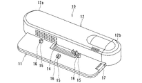
図1は本発明に係る情報処理装置1の構成品である燃料電池ユニット10の一実施形態を示す外観図である。図1に示すように、この燃料電池ユニット10は、情報処理装置本体、例えばノート型パーソナルコンピュータの後部を載置するための載置部11と、燃料電池ユニット本体12とから構成される。燃料電池ユニット本体12には、電気化学反応で発電を行う燃料電池(DMFC)の一単位(セル)を積み重ねて構成したDMFCスタックや、DMFCスタックに対して燃料となるメタノールや空気を注入、循環させるための補機(ポンプやバルブ等)を内蔵している。
FIG. 1 is an external view showing an embodiment of a
また、燃料電池ユニット本体12のユニットケース12a内部の例えば右端に、燃料カートリッジ(図示していない)が着脱可能に内蔵されており、この燃料カートリッジを交換できるように、カバー12bはユニットケース12aの側面に取り外し可能に設けられている。
In addition, a fuel cartridge (not shown) is detachably built in, for example, the right end inside the
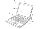
載置部11には図2に示す情報処理装置本体2が載置される。載置部11の上面には、情報処理装置本体2と接続するための接続部としてドッキングコネクタ14が設けられている。一方、情報処理装置本体2の例えば底面後部には、燃料電池ユニット10と接続するための接続部としてドッキングコネクタ(図示していない)が設けられており、燃料電池ユニット10のドッキングコネクタ14と機械的、電気的に接続される。また、載置部11上に三箇所の位置決め突起15とフック16が設けられており、対応して設けられた情報処理装置の底面後部の三箇所の穴に、位置決め突起15とフック16が挿入される。
The information processing apparatus
情報処理装置本体2を燃料電池ユニット10から取り外す時は、図1に示した燃料電池ユニット10のイジェクトボタン17を押すことにより、ロック機構(図示していない)の解除が行われて、容易に取り外すことができる。
When the information processing device
図2は、情報処理装置本体2(例えば、ノート型パーソナルコンピュータ)を燃料電池ユニット10の載置部11の上に載置、接続した時の外観を示す図である。情報処理装置本体2は、本体部3と開閉自在のパネル部4とから構成される。パネル部4は例えばLCD(Liquid Crystal Display)から構成されるディスプレイ68を備えている。
FIG. 2 is a diagram showing an appearance when the information processing apparatus main body 2 (for example, a notebook personal computer) is placed on and connected to the
また、本体部3の上面にはポインタデバイス71、キーボード72、電源スイッチ104等が配設される。
A
なお、図1および図2に示した情報処理装置本体2および燃料電池ユニット10の形状や大きさ、或いはドッキングコネクタ14の形状や位置等は、種々の形態が考えられる。
Various shapes can be considered for the shape and size of the information processing apparatus
また、燃料電池ユニット10は、ドッキングコネクタ14,21を介さずに情報処理装置本体2と一体的に構成された形態でもよい。
Further, the
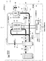
図3は、燃料電池ユニット10の構成について、特に、DMFCスタックとその周辺に設けられた補機による発電メカニズムに関する構成を示したものである。
FIG. 3 shows the configuration of the
燃料電池ユニット10は、発電部40と、燃料電池制御部41とから構成される。燃料電池制御部41は発電部40の制御を行う他、情報処理装置本体2との通信を行う通信制御部としての機能を有する。
The
発電部40は、発電を行うための中心となるDMFCスタック42を有する他、燃料となるメタノールを収納する燃料カートリッジ43を有する。燃料カートリッジ43には高濃度のメタノールが封入されている。燃料カートリッジ43は、燃料を消費した時には容易に交換できるよう、着脱可能となっている。
The
また、一般に、ダイレクトメタノール型燃料電池においては、発電効率をあげるにクロスオーバ現象を低減する必要がある。このために高濃度メタノールを希釈して低濃度化し、これを燃料極47に注入することが有効である。この実現のため、燃料電池ユニット10では、希釈循環システム62を採用しており、発電部40に希釈循環システム62の実現に必要な補機63を設ける。
In general, in a direct methanol fuel cell, it is necessary to reduce the crossover phenomenon in order to increase the power generation efficiency. For this purpose, it is effective to dilute high-concentration methanol to lower the concentration and inject it into the
補機63には液体流路に設けられるものと気体流路に設けられるものがある。
There are
液体流路に設けられる補機63の接続関係は、燃料電池カートリッジ43の出力部から燃料供給ポンプ44が配管接続され、さらに燃料供給ポンプ44の出力部から混合タンク45に接続される。さらに、混合タンク45の出力部は送液ポンプ46に接続され、送液ポンプ46の出力部はDMFCスタック42の燃料極47に接続される。燃料極47の出力部は混合タンク45に配管接続される。また、水回収タンク55の出力部は水回収ポンプ56に配管接続され、水回収ポンプ56は混合タンク45へ接続される。
The
一方、気体流路においては、送気ポンプ50が送気バルブ51を介してDMFCスタック42の空気極52に接続される。空気極52の出力部は凝縮器53に接続される。また、混合タンク45からも、混合タンクバルブ48を介して凝縮器53に接続される。凝縮器53は排気バルブ57を介して排気口58に接続される。また、冷却ファン54は凝縮器53の近傍に配設される。
On the other hand, in the gas flow path, the
次に、燃料電池ユニット10の発電部40の発電メカニズムについて、燃料と空気(酸素)の流れに沿って説明する。
Next, the power generation mechanism of the
まず、燃料カートリッジ43内の高濃度メタノールは、燃料供給ポンプ44によって、混合タンク45に流入する。混合タンク45の内部で高濃度メタノールは、回収された水や燃料極47からの低濃度メタノール(発電反応の残余分)等と混合されて希釈され、低濃度メタノールが生成される。低濃度メタノールの濃度は発電効率の高い濃度(例えば3〜6質量%)を保てるように制御される。この制御は、例えば、濃度センサ60の情報を基に燃料供給ポンプ44によって混合タンク45に供給される高濃度メタノールの量を制御したり、また、混合タンク45に環流する水の量を水回収ポンプ56等で制御することによって実現できる。
First, the high-concentration methanol in the
混合タンク45で希釈されたメタノール水溶液は送液ポンプ46で加圧されて、DMFCスタック42の燃料極(負極)47に注入される。燃料極47では、メタノールの酸化反応が行われることで電子が発生する。酸化反応で生成される水素イオン(H+)はDMFCスタック42内の固体高分子電解質膜42aを透過して空気極(正極)52に達する。
The methanol aqueous solution diluted in the
一方、燃料極47で行われる酸化反応によって生成される二酸化炭素は、反応に供されなかったメタノール水溶液とともに再び混合タンク45に環流する。二酸化炭素は混合タンク45内で気化し、混合タンクバルブ48を介して、凝縮器53へ向かい、最終的には排気バルブ57を介して、排気口58から外部へ排気される。
On the other hand, the carbon dioxide produced by the oxidation reaction performed at the
他方、空気(酸素)の流れは、吸気口49から取り込まれ、送気ポンプ50で加圧され、送気バルブ51を介し空気極(正極)52に注入される。空気極52では、酸素(O2)の還元反応が進行し、外部の負荷からの電子(e―)と、燃料極47からの水素イオン(H+)と、酸素(O2)から水(H2O)が水蒸気として生成される。この水蒸気は空気極52から排出され、凝縮器53に入る。凝縮器53では、冷却ファン54によって水蒸気が冷却されて水(液体)となり、水回収タンク55内に一時的に蓄積される。この回収された水は水回収ポンプ56によって混合タンク45へと環流し、高濃度メタノールを希釈するための希釈循環システム62が構成される。
On the other hand, the flow of air (oxygen) is taken from the
上述にて説明した希釈循環システム62による燃料電池ユニット10の発電メカニズムからわかるように、DMFCスタック42から電力が取り出される、即ち、発電を開始するために、各部のポンプ44,46,50,56やバルブ48、51、57或いは冷却ファン54等の補機63を駆動させる。これによってメタノール水溶液と空気(酸素)がDMFCスタック42内に注入されそこで電気化学反応が進行することによって電力が得られる。一方、発電を停止するには、これらの補機63の駆動を停止させればよい。
As can be seen from the power generation mechanism of the
図4は、燃料電池ユニット10がドッキングコネクタ14,21を介して情報処理装置本体2に接続された状態のシステム構成を示す図である。
FIG. 4 is a diagram showing a system configuration in a state in which the
情報処理装置本体2は、CPU65、主記憶66、ディスプレイコントローラ67、ディスプレイ68、HDD(Hard Disc Drive)69、キーボードコントローラ70、ポインタデバイス71、キーボード72、FDD(Floppy Disc Drive)73、CD−ROMドライバ84,LANインタフェース85、これら構成品間において信号を伝送するバス74、バス74を介して伝送される信号を変換するためのノースブリッジ75、サウスブリッジ76と呼ばれるデバイス等から構成される。
The information
また、情報処理装置本体2の内部に電源部79を設け、ここに二次電池80として、例えばリチウムイオン電池を保有している。電源部79は、制御部77(以降、電源制御部77と記載する。)によって制御される。
In addition, a
燃料電池ユニット10と情報処理装置本体2との電気的インタフェースとして制御系インタフェースと電源系インタフェースとを設ける。制御系インタフェースは情報処理装置本体2の電源制御部77と燃料電池ユニット10の燃料電池制御部41との間にて通信を行うために設けられるインタフェースである。制御系インタフェースを介して情報処理装置本体2と燃料電池ユニット10との間で行われる通信は、例えばI2Cバス78といったシリアルバスを介して行われる。
As an electrical interface between the
電源系インタフェースは、燃料電池ユニット10と情報処理装置本体2との間における電力の授受のために設けられるインタフェースである。例えば、発電部40のDMFCスタック42で発電された電力が燃料電池制御部41およびドッキングコネクタ14、21を介して情報処理装置本体2に供給される。また、電源系インタフェースには、情報処理装置本体2の電源部79から、燃料電池ユニット10内の補機63等への電力供給83もある。
The power system interface is an interface provided for power transfer between the
なお、情報処理装置本体2の電源部79に対してACアダプタ用コネクタ81を介してAC/DC変換された直流電源が供給され、これによって情報処理装置本体2の動作、二次電池(リチウムイオン電池)80の充電が可能である。
Note that a DC power source that is AC / DC converted is supplied to the
図5は、燃料電池ユニット10の燃料電池制御部41と、情報処理装置本体2の電源部79の一実施例における機能系統を示したものである。
FIG. 5 shows a functional system in one embodiment of the fuel
燃料電池ユニット10と情報処理装置本体2とはドッキングコネクタ14、21によって機械的かつ電気的に接続される。ドッキングコネクタ14、21には、燃料電池ユニット10のDMFCスタック42で発電された電力を情報処理装置本体2へ供給するための第1の電源端子(出力電源端子)91と、情報処理装置本体2から燃料電池ユニット10のマイクロコンピュータ95に電源を供給し、かつ補機用電源回路97にスイッチ101を介して電源を供給するための第2の電源端子(補機用入力電源端子)92とを有する。さらに、情報処理装置本体2からEEPROM99および燃料カートリッジ43に内蔵されたEEPROM43aへ電源供給するための第3の電源端子92aを有している。
The
マイクロコンピュータ95は、制御プログラムや制御データ等を記憶するための記憶部95aを内蔵しており、記憶部95aは例えばフラッシュメモリ等で構成される。
The
EEPROM99は例えば燃料電池ユニット10の識別情報が記憶されており、電子的に書き込み可能な不揮発性メモリで構成される。燃料カートリッジ43のEEPROM43aには、例えば燃料カートリッジ43に収納される燃料の種別を示す情報等が記憶され、同様に電子的に書き込み可能な不揮発性メモリで構成される。
The
さらに、ドッキングコネクタ14、21は情報処理装置本体2の電源制御部77と燃料電池ユニット10のマイクロコンピュータ95との通信や、EEPROM99、EEPROM43aとの通信を行うための通信用入出力端子93を有している。
Further, the
図6は、燃料電池ユニット10の発電開始シーケンスおよび発電停止シーケンスにおける状態の遷移を示したものである。図5に示した系統図を参照しつつ図6の状態遷移について説明する。
FIG. 6 shows a state transition in the power generation start sequence and the power generation stop sequence of the
なお、図5において、情報処理装置本体2の二次電池(リチウムイオン電池)80には所定の電力が充電されているものとする。また、図5の中のスイッチは全て開いているものとする。
In FIG. 5, it is assumed that the secondary battery (lithium ion battery) 80 of the information processing apparatus
(1)「ストップステート」ST10:この状態は、情報処理装置本体2と燃料電池ユニット10は接続されているものの、燃料電池ユニット10に設けられるマイクロコンピュータ95や補機63への電力は供給されておらず、DMFCスタック42での発電も行われていない状態である。ただし、第3の電源端子92aを介してEEPROM99およびEEPROM43aには電力が供給されている。
(1) “Stop state” ST10: In this state, the information processing apparatus
(2)「スタンバイステート」ST20:燃料電池ユニット10側に設けられるメインスイッチ103が閉じられると情報処理装置本体2に設けられる電源制御部77は、燃料電池ユニット10での発電が許可されたものと認識する。メインスイッチ103は例えばスライドスイッチ等で構成される。メインスイッチ103が閉じられたことを検出した電源制御部77は、I2Cバス78を介してEEPROM99に記憶されている燃料電池ユニット10の識別情報およびEEPROM43aに記憶されている例えば燃料の種別情報を読み出す。読み出された識別情報や燃料の種別情報が適切なものであると電源制御部77が判断すると、電源制御部77は、情報処理装置2に設けられるスイッチ100を閉じて二次電池80の電力をマイクロコンピュータ95へ供給する。この状態が「スタンバイステート」ST20である。
(2) “Standby state” ST20: When the
「スタンバイステート」ST20では、マイクロコンピュータ95は動作状態となるが、補機63には電源が供給されておらず、DMFCスタック42での発電は開始されていない。
In the “standby state” ST20, the
(3)「ウォームアップステート」ST30:電源制御部77がI2Cバス78を介して発電の開始を指令する「運転ON要求」コマンドをマイクロコンピュータ95に送信すると、このコマンドを受信したマイクロコンピュータ95は燃料電池ユニット10に設けられるスイッチ101を閉じる。この結果、情報処理装置本体2の二次電源80の電力は補機用電源回路97に入力され、さらに補機63へ電力が供給されることによって補機63の駆動が開始される。
(3) “Warm-up state” ST30: When the power
補機63の駆動によってDMFCスタック42へ燃料および空気が供給されDMFCスタック42での発電が開始される。
By driving the
さらに、マイクロコンピュータ95は燃料電池ユニット10に設けられるスイッチ102を閉じ、情報処理装置用電源回路105で所定の電圧に変換した後、発電電力の供給を開始する。
Further, the
ただし、発電出力は、瞬時に定格値に達するわけではないため、定格値に達するまでの状態を「ウォームアップステート」ST30と呼んでいる。 However, since the power generation output does not instantaneously reach the rated value, the state until the rated value is reached is called “warm-up state” ST30.
なお、「運転ON要求」コマンドは、例えば情報処理装置本体2が起動された場合などに電源制御部77がマイクロコンピュータ95へ送信する。具体的には、例えば情報処理装置本体2に設けられた電源スイッチ104がユーザによって押されたことを電源制御部77が検出することによって情報処理装置本体2自体を起動させるとともに、電源制御部77が「運転ON要求」コマンドを燃料電池ユニット10に設けられるマイクロコンピュータ95へ送信する。
The “operation ON request” command is transmitted from the power
(4)「オンステート」ST40:マイクロコンピュータ95は、例えばDMFCスタック42の出力電圧およびDMFCスタック42の温度をモニタすることにより、DMFCスタック42の出力が定格値に達したと判断すると、燃料電池ユニット10に設けられるスイッチ101を開き、補機63への電力供給源を情報処理装置本体2からDMFCスタック42に切り替える。この状態が「オンステート」ST40である。
(4) “On-state” ST40: When the
以上が「ストップステート」ST10から「オンステート」ST40への基本的な処理の流れであり、「オンステート」ST40が燃料電池ユニット10の通常の発電状態である。
The above is the basic processing flow from the “stop state” ST10 to the “on state” ST40, and the “on state” ST40 is the normal power generation state of the
(5)「クールダウンステート」ST50:燃料電池ユニット10が「オンステート」ST40あるいは「ウォームアップステート」ST30にある時に、電源制御部77から燃料電池ユニット10に設けられるマイクロコンピュータ95に対して発電の停止を指令する「運転OFF要求」コマンドが送信されると、燃料電池ユニット10は状態を「クールダウンステート」ST50に遷移させる。「クールダウンステート」ST50における処理内容は次の通りである。
(5) “Cool-down state” ST50: When the
まず、マイクロコンピュータ95が燃料電池ユニット10内に設けられるスイッチ101を閉じることで、補機63を駆動させるために使用される補機用電源回路97の電力源を、第1の電源端子92を介して供給される二次電池80に切替える。
First, the
さらに,マイクロコンピュータ95が燃料電池ユニット内に設けられるスイッチ102を開くことで、DMFCスタック42にて発電される電力の情報処理装置18への供給を停止する。
Further, the
次に、マイクロコンピュータ95が送気ポンプ50を停止させるとともに、送液ポンプ46を作動させこのポンプ作動状態を所定期間継続する。このポンプ作動によって燃料極47の内部の送液経路内に付着した二酸化炭素の気泡を流失・除去することができる。
Next, the
次に、マイクロコンピュータ95が送液ポンプ46を停止し、送気ポンプ50を最大能力で作動させる。このポンプ作動状態を所定期間継続する。このポンプ作動によって空気極52の内部の送気経路内に付着した水滴を流失・除去することができる。
Next, the
DMFCスタックの発電によって発生した気泡や水滴を、発電の停止シーケンスのなかで自動的に流出・除去させることによって、次回発電を開始する時の発電効率を向上させることが可能となる。 By automatically flowing out and removing bubbles and water droplets generated by the power generation of the DMFC stack in the power generation stop sequence, it is possible to improve the power generation efficiency when starting the next power generation.
その後、燃料電池ユニット10の周囲外気から塵埃等の不要物が混入すること、および燃料電池ユニット10内にセットされる液体燃料が漏れることを避けるために、排気バルブ57や送気バルブ51を閉じる。さらに、マイクロコンピュータ95は補機用電源回路97から補機63への電力の供給を停止する。
Thereafter, the
以上が燃料電池ユニット10で行われる「クールダウンステート」ST50の処理内容である。
The above is the processing content of the “cool down state” ST50 performed in the
「クールダウンステート」ST50の処理は、例えば概ね30秒間行われる。クールダウン処理終了後は、燃料電池ユニット10に設けられるスイッチ101を開くことによって補機63の駆動を停止させ、「スタンバイステート」ST20に戻る。
The “cool-down state” ST50 is performed, for example, for approximately 30 seconds. After completion of the cool-down process, the driving of the
図7は、例えばマイクロコンピュータ95に設けられる記憶部95aに記憶される制御プログラム95bを更新する際の状態遷移を説明する図である。
FIG. 7 is a diagram for explaining the state transition when the control program 95b stored in the
制御プログラム95bの更新は、図7の「更新ステート」ST60で行われる。「更新ステート」ST60への遷移は、情報処理装置本体2に設けられる電源制御部77が送信する「更新」コマンドをマイクロコンピュータ95が受信することによって行われる。
The control program 95b is updated in the “update state” ST60 in FIG. The transition to the “update state” ST60 is performed when the
燃料電池ユニット10の状態が「スタンバイステート」ST20である場合、燃料電池ユニット10の状態は「更新ステート」ST60に遷移することが可能な状態である。
When the state of the
燃料電池ユニット10の状態が「ストップステート」ST10である場合、燃料電池ユニット10に設けられるメインスイッチ103をオンにすることで、「スタンバイステート」ST20に遷移する。燃料電池ユニット10の状態が「スタンバイステート」ST20において、マイクロコンピュ―タ95が「更新」コマンドを受信すると「更新ステート」ST60に遷移する。
When the state of the
一方、燃料電池ユニット10が「ウォームアップステート」ST30或いは「オンステート」ST40にある場合、マイクロコンピュータ95が「更新」コマンドを受信した後に、燃料電池ユニット10の状態が「クールダウンステート」ST50に遷移する。「クールダウンステート」ST50にて、燃料電池ユニット10は所定期間クールダウン処理を行った後、「スタンバイステート」ST20に遷移する。燃料電池ユニット10がクールダウン処理を行う理由は、次回、発電を開始する場合に発電効率を向上させるためである。
On the other hand, when the
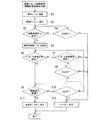
図8は、制御プログラム更新処理(情報処理装置本体2側)の手順を説明するフローチャートである。
FIG. 8 is a flowchart for explaining the procedure of the control program update process (information processing apparatus
まず、電源制御部77は、燃料電池ユニット10に設けられるマイクロコンピュータ95に「更新」コマンドを送信する(S1)。さらに、ユーザの利便性のため、例えば情報処理装置本体2のパネル部4のディスプレイ68に、制御プログラム95bを更新中である旨を表示させる(S2)。
First, the power
図9(a)は、ディスプレイ68への表示例を示した図である。
FIG. 9A is a diagram showing a display example on the
マイクロコンピュータ95は「更新」コマンドを受信すると、燃料電池ユニット10の状態が「スタンバイステート」ST20である、つまり、プログラム更新準備完了状態であることを示す信号(以下、「更新準備完了」信号と称す。)を、電源制御部77に送信する。また、マイクロコンピュータ95は電源制御部77から送信される「更新」コマンドを受信すると、燃料電池ユニット10の状態を「更新ステート」に遷移させる。その後、電源制御部77は更新用制御プログラム95cをマイクロコンピュータ95に送信する。
When the
ここで、情報処理装置本体2には、マイクロコンピュータ95に送信される更新用制御プログラム95cが入力されていなければならい。更新用制御プログラム95cの情報処理装置本体2への入力方法は、例えば、図4のシステム構成図に示したLANインタフェース85を介して電気通信回線86(例えばインターネット等)から更新用制御プログラム95cを入力する方法や、CD−ROMに記憶されている更新用制御プログラム95cをCD−ROMドライバ84を介して入力する方法等が考えられる。更新用制御プログラム95cの情報処理装置本体2への入力方法は、上記にて説明した方法に限定されず、情報処理装置本体2が備えたその他データ入力方法を適用することが可能である。
Here, the information processing apparatus
なお、電源制御部77が所定期間以内に「更新準備完了」信号を受信しない場合は、タイムアウトであるとして(S4のyes)、ディスプレイ68にエラーメッセージを表示する。この表示内容は例えば図9(c)に示した内容である。
When the power
一方、電源制御部77が所定期間以内に「更新準備完了」信号を受信すると(S3のyes)、電源制御部77は更新用制御プログラム95cをマイクロコンピュータ95へ送信する(S5)。
On the other hand, when the power
次に、電源制御部77は、マイクロコンピュータ95から送信される「プログラム受信正常」信号を受信したか否かを判断する(S6)。「プログラム受信正常」信号とは、マイクロコンピュータ95が更新用制御プログラム95cを正常に受信したことを示す情報である。
Next, the power
電源制御部77が「プログラム受信正常」を受信すると(S6のyes)、電源制御部77は、マイクロコンピュータ95から送信される「更新完了」信号を受信したか否かを判断する(S9)。
When the
「更新完了」信号とは、マイクロコンピュータ95において更新用制御プログラム95cが正常に更新されたことを示す情報である。
The “update complete” signal is information indicating that the update control program 95c has been normally updated in the
電源制御部77が「更新完了」信号を受信すると(S9のyes)、燃料電池ユニット10側にて更新用制御プログラム95の更新が完了したことを示すメッセージ(例えば図9(b))をディスプレイ68に表示する(S11)。その後、制御プログラム更新処理を終了する。
When the power
一方、電源制御部77が「プログラム受信正常」を受信せず(S6のno)、かつ「プログラム受信異常」信号を受信した場合(S7のyes)は、ディスプレイ68にエラーメッセージ(例えば図9(c))が表示される(S12)。その後、制御プログラム更新処理を終了する。
On the other hand, if the power
「プログラム受信異常」信号とは、マイクロコンピュータ95が更新用制御プログラム95cを正常に受信できなかったことを示す情報である。
The “program reception abnormality” signal is information indicating that the
この他、電源制御部77が「プログラム受信正常」または「プログラム受信異常」のいずれの信号を所定期間に受信しなかった(タイムアウト)場合(S8のyes)であっても、ディスプレイ68にエラーメッセージを表示して(S12)、その後、制御プログラム更新処理を終了する。
In addition, even if the power
また、電源制御部77が「更新完了」を所定期間内に受信しなかった場合(S10のyes)であっても、ディスプレイ68にエラーメッセージを表示し(S12)、制御プログラム更新処理を終了する。
Even if the power
図10は、燃料電池ユニット10側における制御プログラム更新処理手順を示したフローチャートである。
FIG. 10 is a flowchart showing a control program update processing procedure on the
まず、マイクロコンピュータ95は、電源制御部77から「更新」コマンドを受信したか否かを判断する(S20)。マイクロコンピュータ95が「更新」コマンドを受信すると(S20のyes)、マイクロコンピュータ95は、燃料電池ユニット10にて行われている発電の停止処理を実施する(S21)。
First, the
ステップ21(S21)の燃料電池ユニット10にて行われる発電停止処理の詳細を図11に示す。
Details of the power generation stop process performed in the
図11のステップ21aないし21cにおいて、マイクロコンピュータ95は、燃料電池ユニット10の状態が「スタンバイステート」ST20、「ウォームアップステート」ST30或いは「オンステート」ST40のいずれであるかを判断する。
In steps 21a to 21c of FIG. 11, the
燃料電池ユニット10の状態が「スタンバイステート」ST20の状態である場合は(S21aのyes)、その状態が維持される(S21e)。
When the state of the
一方、燃料電池ユニット10の状態が「ウォームアップステート」ST30の場合(s21bのyes)、或いは「オンステート」ST40の場合(S21cのyes)には「クールダウンステート」ST50に遷移させて、クールダウン処理を行なう(S21d)。その後「スタンバイステート」ST20に移行させる(S21e)。
On the other hand, when the state of the
このように、燃料電池ユニット10の発電停止処理(S21)によって、燃料電池ユニット10は更新コマンドを受信した時の状態にかかわらず「スタンバイステート」ST20に移行させる。
As described above, by the power generation stop process (S21) of the
「スタンバイステート」ST20に移行させた後(図10のステップ21)、マイクロコンピュータ95は電源制御部77に対して「更新準備完了」信号を送信する(S22)。
After shifting to the “standby state” ST20 (
この後、電源制御部77から送信されてくる更新用制御プログラム95cを受信する(S23)。
Thereafter, the update control program 95c transmitted from the power
マイクロコンピュータ95は、更新用制御プログラム95cが正常に受信されたことを例えばチェックサムを用いて判断する(S24)。
The
チェックサム法はデータを送受信する際の誤り検出方法の一つである。送信前にデータを所定長のブロックに分割し、それぞれのブロック内のデータを数値とみなして合計を取ったものをチェックサムと呼ぶ。求めたチェックサムはデータと一緒に送信する。受信側では送られてきたデータ列から同様にチェックサムを計算し、送信側から送られてきたチェックサムと一致するかどうかを検査する。両者が異なれば、通信系路上でデータに誤りが生じたと判断するものである。 The checksum method is one of error detection methods when transmitting / receiving data. The data is divided into blocks of a predetermined length before transmission, and the sum obtained by regarding the data in each block as a numerical value is called a checksum. The obtained checksum is transmitted together with the data. On the receiving side, a checksum is calculated in the same manner from the data string sent, and it is checked whether it matches the checksum sent from the sending side. If they are different, it is determined that an error has occurred in the data on the communication path.
チェックサムが正常の場合は、マイクロコンピュータ95は「プログラム受信正常」情報を電源制御部77に送信する(S25)。
If the checksum is normal, the
その後、マイクロコンピュータ95の記憶部95aに記憶されている制御プログラム95b(旧プログラム)を、情報処理装置本体2の電源制御部77から送られてきた更新用制御プログラム95c(新プログラム)に更新する(S27)。
Thereafter, the control program 95b (old program) stored in the
さらに記憶部95aの所定のデータ領域に対して初期化処理を実行させることにより、更新用制御プログラム95cを実行可能な状態に設定する(S28)。
Further, the update control program 95c is set in an executable state by executing an initialization process on a predetermined data area of the
その後、電源制御部77へ更新処理が完了したことを示す「更新完了」信号を送信する(S29)。「更新完了」信号を送信後、燃料電池ユニット10は状態「スタンバイステート」に戻して(S30)、制御プログラムの更新処理を終了する。
Thereafter, an “update complete” signal indicating that the update process has been completed is transmitted to the power supply control unit 77 (S29). After transmitting the “update complete” signal, the
一方、チェックサムが異常と判断された場合は、「プログラム受信異常」を電源制御部77に対して送信した後(S26)、「スタンバイステート」に戻して(S30)、制御プログラムの更新処理を終了する。 On the other hand, if it is determined that the checksum is abnormal, “program reception abnormality” is transmitted to the power supply control unit 77 (S26), and then returned to the “standby state” (S30). finish.
上述した燃料電池ユニット10の制御プログラム更新処理によれば、
(1)情報処理装置1が保有しているデータバス(例えばI2Cバス)を用いて更新用制御プログラム95cを燃料電池ユニットに設けられるマイクロコンピュータ95へ送信できるため、新たなデータ書き込み用のケーブルインターフェースが不要である。
(2)更新用制御プログラム95cの入手は、情報処理装置本体2が有しているLANインタフェース85やCD−ROMドライバ84等を利用することによって容易に情報処理装置本体2に入力できる。
(3)情報処理装置本体2の操作によって更新コマンドを送信することができ、この更新コマンドの送信のみによって制御プログラムの更新処理を自動的に行うことができる。 (4)燃料電池ユニット10が発電中であっても自動的に発電を停止させ、かつ自動的に制御プログラムの更新処理に必要な電力を情報処理装置本体2から燃料電池ユニット10に供給することができる。
等の優れた効果により、ユーザにとって利便性の高い情報処理装置あるいは情報処理装置の制御方法を提供することができる。
According to the control program update process of the
(1) Since the update control program 95c can be transmitted to the
(2) The update control program 95c can be easily input to the information
(3) The update command can be transmitted by operating the information processing apparatus
With such excellent effects, it is possible to provide an information processing apparatus that is highly convenient for the user or a method for controlling the information processing apparatus.
なお、本発明は上記実施形態そのままに限定されるものではなく、実施段階ではその要旨を逸脱しない範囲で構成要素を変形して具体化できる。また、上記実施形態に開示されている複数の構成要素の適宜な組み合わせにより、種々の発明を形成できる。例えば、実施形態に示される全構成要素から幾つかの構成要素を削除してもよい。さらに、異なる実施形態にわたる構成要素を適宜組み合わせても良い。 Note that the present invention is not limited to the above-described embodiment as it is, and can be embodied by modifying the constituent elements without departing from the scope of the invention in the implementation stage. In addition, various inventions can be formed by appropriately combining a plurality of constituent elements disclosed in the embodiment. For example, some components may be deleted from all the components shown in the embodiment. Furthermore, the constituent elements over different embodiments may be appropriately combined.
1 情報処理装置
2 情報処理装置本体
3 本体部
4 パネル部
10 燃料電池ユニット
14 ドッキングコネクタ(燃料電池ユニット側)
21 ドッキングコネクタ(情報処理装置側)
40 発電部
41 燃料電池制御部
42 DMFCスタック
46 送液ポンプ
50 送気ポンプ
51 送気バルブ
57 排気バルブ
63 補機
68 ディスプレイ
70 キーボードコントローラ
72 キーボード
77 電源制御部
78 I2Cバス
79 電源部
80 二次電池
84 CD−ROMドライバ
85 LANインタフェース
86 電気通信回線
95 マイクロコンピュータ
95a 記憶部
95b 制御プログラム
95c 更新用制御プログラム
97 補機用電源回路
99 不揮発性メモリ(EEPROM)
103 メインスイッチ
104 電源スイッチ
DESCRIPTION OF SYMBOLS 1
21 Docking connector (information processing equipment side)
40
103
Claims (10)
外部から第2のプログラムの入力を受ける入力部と、
前記前記燃料電池ユニットと通信を行う制御部と、
二次電池と、
を備え、
前記燃料電池ユニットがスタンバイ状態にあり、前記燃料電池制御部が前記二次電池から供給される電力によって動作しているときに、前記第1のプログラムは前記第2のプログラムによって更新される、
ことを特徴とする情報処理装置。 A fuel cell, a storage unit for storing a first program, the connectable information processing apparatus to the fuel cell unit and a fuel cell controller,
An input unit for receiving an input of the second program from the outside ;
A controller that communicates with the fuel cell unit ;
A secondary battery,
With
The first program is updated by the second program when the fuel cell unit is in a standby state and the fuel cell control unit is operating with electric power supplied from the secondary battery.
An information processing apparatus characterized by that.
前記制御部は前記シリアルバスを介して前記燃料電池制御部と通信することを特徴とする請求項1記載の情報処理装置。 Further comprising a serial bus connecting between the controller and the fuel cell controller,
The information processing apparatus according to claim 1, wherein the control unit communicates with the fuel cell control unit via the serial bus.
前記第1のプログラムは、前記燃料電池を用いて行われる発電が停止した状態において更新されることを特徴とする請求項1記載の情報処理装置。 The control unit transmits a command for updating the first program by the second program to the fuel cell unit,
The information processing apparatus according to claim 1, wherein the first program is updated in a state where power generation performed using the fuel cell is stopped.
前記制御部は、前記第1のプログラムが更新中であることを示す情報を、前記燃料電池ユニットから受信し、
前記表示部は、前記制御部が受信した、前記第1のプログラムが更新中であることを示す情報に基づいて、前記第1のプログラムが更新中であることを表示することを特徴とする請求項1記載の情報処理装置。 A display unit for displaying information;
The control unit receives information indicating that the first program is being updated from the fuel cell unit,
The display unit displays that the first program is being updated based on information received by the control unit and indicating that the first program is being updated. Item 6. The information processing apparatus according to Item 1.
前前記二次電池から前記燃料電池制御部への電力供給を停止した後、前記制御部は前記燃料電池ユニットに前記燃料電池を用いた発電を再開させるコマンドを送信することを特徴とする請求項1記載の情報処理装置。 The control unit receives information indicating that the update of the first program is completed from the fuel cell unit, and then stops power supply from the secondary battery to the fuel cell control unit ,
The power supply from the said secondary battery to the said fuel cell control part is stopped, The said control part transmits the command which restarts the electric power generation using the said fuel cell to the said fuel cell unit, It is characterized by the above-mentioned. 1. An information processing apparatus according to 1.
前記燃料電池ユニットを制御する第2のプログラムを外部から入力し、
前記燃料電池ユニットに前記第2のプログラムの送信をし、
前記燃料電池ユニットがスタンバイ状態にあり、前記燃料電池制御部が前記情報処理装置が具備する二次電池から供給される電力によって動作しているときに、前記第1のプログラムを前記第2のプログラムによって更新する、
ことを特徴とする情報処理装置の制御方法。 In a control method of an information processing apparatus connectable to a fuel cell unit having a fuel cell, a storage unit for storing a first program, and a fuel cell control unit ,
A second program for controlling the fuel cell unit is input from the outside,
Sending the second program to the fuel cell unit;
The first program is changed to the second program when the fuel cell unit is in a standby state and the fuel cell control unit is operating with electric power supplied from a secondary battery included in the information processing apparatus. Update by,
A method for controlling an information processing apparatus.
前記燃料電池ユニットに前記第1のプログラムの更新を指令するコマンドを送信し、
前記燃料電池を用いた発電を停止させ、
前記燃料電池ユニットから前記第1のプログラムの更新のための準備が完了したことを示す情報を受信することを特徴とする請求項8に記載の情報処理装置の制御方法。 Before transmitting the second program to the fuel cell unit, and supplies power of the secondary battery to the fuel cell controller,
A command for instructing the fuel cell unit to update the first program;
Stopping power generation using the fuel cell;
9. The information processing apparatus control method according to claim 8 , wherein information indicating that preparation for updating the first program is completed is received from the fuel cell unit.
前記燃料電池ユニットから前記更新が終了したことを示す情報を受信し、
前記燃料電池を用いた発電を再開させることを特徴とする請求項8に記載の情報処理装置の制御方法。 After updating the first program by the second program ,
Receiving information indicating that the update has been completed from the fuel cell unit;
The method for controlling an information processing apparatus according to claim 8, wherein power generation using the fuel cell is resumed.
Priority Applications (4)
| Application Number | Priority Date | Filing Date | Title |
|---|---|---|---|
| JP2004108044A JP4551685B2 (en) | 2004-03-31 | 2004-03-31 | Information processing apparatus and information processing apparatus control method |
| CNA2005800157172A CN1954285A (en) | 2004-03-31 | 2005-03-23 | Information processing apparatus, fuel cell unit, and program updating method thereof |
| PCT/JP2005/005275 WO2005098576A1 (en) | 2004-03-31 | 2005-03-23 | Image processor, fuel cell unit, and method for updating program for the fuel unit |
| US11/528,559 US7620805B2 (en) | 2004-03-31 | 2006-09-28 | Apparatus for updating program in a fuel cell unit |
Applications Claiming Priority (1)
| Application Number | Priority Date | Filing Date | Title |
|---|---|---|---|
| JP2004108044A JP4551685B2 (en) | 2004-03-31 | 2004-03-31 | Information processing apparatus and information processing apparatus control method |
Publications (2)
| Publication Number | Publication Date |
|---|---|
| JP2005293281A JP2005293281A (en) | 2005-10-20 |
| JP4551685B2 true JP4551685B2 (en) | 2010-09-29 |
Family
ID=35125248
Family Applications (1)
| Application Number | Title | Priority Date | Filing Date |
|---|---|---|---|
| JP2004108044A Expired - Fee Related JP4551685B2 (en) | 2004-03-31 | 2004-03-31 | Information processing apparatus and information processing apparatus control method |
Country Status (4)
| Country | Link |
|---|---|
| US (1) | US7620805B2 (en) |
| JP (1) | JP4551685B2 (en) |
| CN (1) | CN1954285A (en) |
| WO (1) | WO2005098576A1 (en) |
Families Citing this family (7)
| Publication number | Priority date | Publication date | Assignee | Title |
|---|---|---|---|---|
| KR20080053886A (en) * | 2006-12-11 | 2008-06-16 | 후지 덴키 홀딩스 가부시키가이샤 | Fuel cell power generation device |
| JP5184224B2 (en) * | 2008-06-19 | 2013-04-17 | 本田技研工業株式会社 | Control device rewriting system for fuel cell vehicle |
| JP2012128615A (en) * | 2010-12-15 | 2012-07-05 | Panasonic Corp | Gas equipment |
| US9292061B2 (en) * | 2011-10-20 | 2016-03-22 | Intelligent Energy Limited | Detachable fuel cartridge defining the base of a computer peripheral device to supply fuel to a fuel cell for powering a computer apparatus |
| TW201324120A (en) * | 2011-10-20 | 2013-06-16 | Intelligent Energy Ltd | Fuel cell for powering computer apparatus |
| JP6280778B2 (en) * | 2014-03-24 | 2018-02-14 | 大阪瓦斯株式会社 | Fuel cell system |
| JP6726120B2 (en) * | 2017-02-24 | 2020-07-22 | 京セラ株式会社 | POWER SYSTEM, POWER SYSTEM CONTROL METHOD, AND POWER SYSTEM |
Citations (6)
| Publication number | Priority date | Publication date | Assignee | Title |
|---|---|---|---|---|
| JP2002073359A (en) * | 2000-08-28 | 2002-03-12 | Nec Access Technica Ltd | Program rewrite method for device having a plurality of cpu circuits |
| JP2002169629A (en) * | 2000-11-30 | 2002-06-14 | Toshiba Corp | Information processing equipment |
| JP2003223243A (en) * | 2002-01-29 | 2003-08-08 | Toshiba Corp | Information equipment |
| JP2003229160A (en) * | 2002-02-05 | 2003-08-15 | Matsushita Electric Ind Co Ltd | Fuel cell system and sales method of fuel cell system |
| JP2003346823A (en) * | 2002-05-22 | 2003-12-05 | Matsushita Electric Ind Co Ltd | Power source system |
| JP2004505422A (en) * | 2000-07-28 | 2004-02-19 | メタリック パワー インコーポレイテッド | Power management system and its management method |
Family Cites Families (13)
| Publication number | Priority date | Publication date | Assignee | Title |
|---|---|---|---|---|
| GB8528472D0 (en) * | 1985-11-19 | 1985-12-24 | British Aerospace | Battery state of charge indicator |
| CN2100660U (en) * | 1991-08-31 | 1992-04-01 | 马希光 | Chargeable solar computer |
| US6029119A (en) * | 1996-01-16 | 2000-02-22 | Compaq Computer Corporation | Thermal management of computers |
| US6387556B1 (en) * | 1997-11-20 | 2002-05-14 | Avista Laboratories, Inc. | Fuel cell power systems and methods of controlling a fuel cell power system |
| JP2000010666A (en) | 1998-06-19 | 2000-01-14 | Toshiba Corp | Computer system and flash rom rewriting method |
| US6286109B1 (en) * | 1998-06-30 | 2001-09-04 | Digital Equipment Corporation | Method and apparatus for reducing heat generation in a portable computer |
| US6326097B1 (en) * | 1998-12-10 | 2001-12-04 | Manhattan Scientifics, Inc. | Micro-fuel cell power devices |
| US6383670B1 (en) * | 1999-10-06 | 2002-05-07 | Idatech, Llc | System and method for controlling the operation of a fuel processing system |
| US6713201B2 (en) | 2001-10-29 | 2004-03-30 | Hewlett-Packard Development Company, L.P. | Systems including replaceable fuel cell apparatus and methods of using replaceable fuel cell apparatus |
| US7222001B2 (en) * | 2002-05-14 | 2007-05-22 | Plug Power Inc. | System for monitoring and controlling fuel cell-based power generation units |
| US20040081867A1 (en) * | 2002-10-23 | 2004-04-29 | Edlund David J. | Distributed fuel cell network |
| JP3842744B2 (en) * | 2003-02-28 | 2006-11-08 | 株式会社東芝 | Electronic device and power supply status display method for the same |
| JP3764429B2 (en) | 2003-02-28 | 2006-04-05 | 株式会社東芝 | Electronic device and power supply switching control method for electronic device |
-
2004
- 2004-03-31 JP JP2004108044A patent/JP4551685B2/en not_active Expired - Fee Related
-
2005
- 2005-03-23 WO PCT/JP2005/005275 patent/WO2005098576A1/en active Application Filing
- 2005-03-23 CN CNA2005800157172A patent/CN1954285A/en active Pending
-
2006
- 2006-09-28 US US11/528,559 patent/US7620805B2/en not_active Expired - Fee Related
Patent Citations (6)
| Publication number | Priority date | Publication date | Assignee | Title |
|---|---|---|---|---|
| JP2004505422A (en) * | 2000-07-28 | 2004-02-19 | メタリック パワー インコーポレイテッド | Power management system and its management method |
| JP2002073359A (en) * | 2000-08-28 | 2002-03-12 | Nec Access Technica Ltd | Program rewrite method for device having a plurality of cpu circuits |
| JP2002169629A (en) * | 2000-11-30 | 2002-06-14 | Toshiba Corp | Information processing equipment |
| JP2003223243A (en) * | 2002-01-29 | 2003-08-08 | Toshiba Corp | Information equipment |
| JP2003229160A (en) * | 2002-02-05 | 2003-08-15 | Matsushita Electric Ind Co Ltd | Fuel cell system and sales method of fuel cell system |
| JP2003346823A (en) * | 2002-05-22 | 2003-12-05 | Matsushita Electric Ind Co Ltd | Power source system |
Also Published As
| Publication number | Publication date |
|---|---|
| US20070020493A1 (en) | 2007-01-25 |
| JP2005293281A (en) | 2005-10-20 |
| US7620805B2 (en) | 2009-11-17 |
| CN1954285A (en) | 2007-04-25 |
| WO2005098576A1 (en) | 2005-10-20 |
Similar Documents
| Publication | Publication Date | Title |
|---|---|---|
| US7618727B2 (en) | Fuel cell unit, control method for fuel cell unit, and information processing apparatus | |
| WO2005099007A1 (en) | Fuel cell unit, information processing device, and power source controlling method for information processing device | |
| US7620805B2 (en) | Apparatus for updating program in a fuel cell unit | |
| US20060083966A1 (en) | Fuel cell unit and method for controlling liquid volume | |
| JP4837015B2 (en) | Information processing apparatus system and charging control method | |
| US20070048566A1 (en) | Fuel cell unit, control method for fuel cell unit, and information processing apparatus | |
| US20040183501A1 (en) | Electronic apparatus, electronic system, and method of controlling operation of the same | |
| JP3713496B2 (en) | Electronic device and power control method for electronic device | |
| US7879473B2 (en) | Fuel cell unit, control method thereof, information processing apparatus, and power supply control method thereof | |
| JP3720024B2 (en) | Electronic device system and operation control method | |
| JP2004265787A (en) | Direct methanol fuel cell system | |
| JP2005078353A (en) | Electronic device system and method for supplying electric power | |
| JP2007273388A (en) | Fuel cell system and operation control method therefor | |
| US20060068241A1 (en) | Information processing apparatus system, fuel cell unit, and display method thereof | |
| JP2006106887A (en) | Information processor system, fuel-cell unit and method for controlling charging | |
| JP4805551B2 (en) | Information processing apparatus system and power supply method | |
| JP4746277B2 (en) | FUEL CELL UNIT, INFORMATION PROCESSING DEVICE, AND METHOD FOR POWER SUPPLYING INFORMATION PROCESSING DEVICE | |
| JP2005242909A (en) | Information processing equipment and power supply control method of information processing equipment | |
| JP2005235784A (en) | Electronic apparatus system and method of operation control |
Legal Events
| Date | Code | Title | Description |
|---|---|---|---|
| A621 | Written request for application examination |
Free format text: JAPANESE INTERMEDIATE CODE: A621 Effective date: 20070316 |
|
| A131 | Notification of reasons for refusal |
Free format text: JAPANESE INTERMEDIATE CODE: A131 Effective date: 20091110 |
|
| A521 | Request for written amendment filed |
Free format text: JAPANESE INTERMEDIATE CODE: A523 Effective date: 20091215 |
|
| TRDD | Decision of grant or rejection written | ||
| A01 | Written decision to grant a patent or to grant a registration (utility model) |
Free format text: JAPANESE INTERMEDIATE CODE: A01 Effective date: 20100615 |
|
| A01 | Written decision to grant a patent or to grant a registration (utility model) |
Free format text: JAPANESE INTERMEDIATE CODE: A01 |
|
| A61 | First payment of annual fees (during grant procedure) |
Free format text: JAPANESE INTERMEDIATE CODE: A61 Effective date: 20100712 |
|
| FPAY | Renewal fee payment (event date is renewal date of database) |
Free format text: PAYMENT UNTIL: 20130716 Year of fee payment: 3 |
|
| LAPS | Cancellation because of no payment of annual fees |