JP4548264B2 - Vehicle alternator - Google Patents
Vehicle alternator Download PDFInfo
- Publication number
- JP4548264B2 JP4548264B2 JP2005222599A JP2005222599A JP4548264B2 JP 4548264 B2 JP4548264 B2 JP 4548264B2 JP 2005222599 A JP2005222599 A JP 2005222599A JP 2005222599 A JP2005222599 A JP 2005222599A JP 4548264 B2 JP4548264 B2 JP 4548264B2
- Authority
- JP
- Japan
- Prior art keywords
- rotor
- ribs
- housing
- cooling air
- width
- Prior art date
- Legal status (The legal status is an assumption and is not a legal conclusion. Google has not performed a legal analysis and makes no representation as to the accuracy of the status listed.)
- Expired - Fee Related
Links
Images


Classifications
-
- H—ELECTRICITY
- H02—GENERATION; CONVERSION OR DISTRIBUTION OF ELECTRIC POWER
- H02K—DYNAMO-ELECTRIC MACHINES
- H02K5/00—Casings; Enclosures; Supports
- H02K5/04—Casings or enclosures characterised by the shape, form or construction thereof
- H02K5/18—Casings or enclosures characterised by the shape, form or construction thereof with ribs or fins for improving heat transfer
-
- H—ELECTRICITY
- H02—GENERATION; CONVERSION OR DISTRIBUTION OF ELECTRIC POWER
- H02K—DYNAMO-ELECTRIC MACHINES
- H02K5/00—Casings; Enclosures; Supports
- H02K5/04—Casings or enclosures characterised by the shape, form or construction thereof
- H02K5/20—Casings or enclosures characterised by the shape, form or construction thereof with channels or ducts for flow of cooling medium
- H02K5/207—Casings or enclosures characterised by the shape, form or construction thereof with channels or ducts for flow of cooling medium with openings in the casing specially adapted for ambient air
-
- H—ELECTRICITY
- H02—GENERATION; CONVERSION OR DISTRIBUTION OF ELECTRIC POWER
- H02K—DYNAMO-ELECTRIC MACHINES
- H02K9/00—Arrangements for cooling or ventilating
- H02K9/02—Arrangements for cooling or ventilating by ambient air flowing through the machine
- H02K9/04—Arrangements for cooling or ventilating by ambient air flowing through the machine having means for generating a flow of cooling medium
- H02K9/06—Arrangements for cooling or ventilating by ambient air flowing through the machine having means for generating a flow of cooling medium with fans or impellers driven by the machine shaft
Landscapes
- Engineering & Computer Science (AREA)
- Power Engineering (AREA)
- Physics & Mathematics (AREA)
- Thermal Sciences (AREA)
- Motor Or Generator Cooling System (AREA)
- Motor Or Generator Frames (AREA)
Description
本発明は、乗用車やトラック等に搭載される車両用交流発電機に関する。 The present invention relates to a vehicle AC generator mounted on a passenger car, a truck, or the like.
近年、車両走行抵抗の低減のためのスラントノーズ化や、車室内居住空間の確保のニーズからエンジンルームがますます狭小化する中で、車両用交流発電機の搭載スペースに余裕がなくなってきている。 また、燃費向上のためエンジン回転は下げられ車両用交流発電機の回転も下がっている。しかしその一方で、安全制御機器等の電気負荷の増加が求められ、ますます発電能力の向上が求められている。 即ち小型で高出力の車両用交流発電機を安価に提供することが求められている。 In recent years, the space for mounting AC generators for vehicles has been reduced as the engine room is becoming more and more narrow due to the need for slant nose to reduce vehicle running resistance and the need to secure a vehicle interior living space. . In addition, the engine speed has been lowered to improve fuel efficiency, and the rotation of the vehicle alternator has also decreased. However, on the other hand, there is a demand for an increase in electrical loads such as safety control devices, and an increase in power generation capacity is demanded more and more. That is, it is required to provide a small and high output AC generator for a vehicle at low cost.
また、車外騒音低減の社会的要請や、車室内静粛性向上による商品性向上の狙いから、近年ますますエンジン騒音が低下してきており、比較的高速で回転する補機、とりわけ車両用交流発電機の騒音が耳につきやすい状況となってきた。 In addition, engine noise has been decreasing in recent years due to social demands for reducing noise outside the vehicle and the aim of improving product quality by improving the quietness of the passenger compartment. Auxiliaries that rotate at relatively high speeds, especially AC generators for vehicles. The noise has become easy to hear.
従来、ハウジングの冷却風吐出窓近傍の形状を改良することにより、騒音を低減したり、冷却性を向上したりする各種の技術が知られている。例えば、冷却風吐出窓を形成するリブを流線形にすることにより冷却風の抵抗を低減して冷却風の流れを円滑にする従来構造(例えば、特許文献1参照。)や、ハウジングに設けられた支持部(サポート部)近傍のリブの傾斜を工夫することにより冷却風の抵抗を低減して冷却風量を増加させた従来構造(例えば、特許文献2参照。)などが知られている。
ところで、上述した特許文献1、2に開示された従来構造では、ハウジングに形成されたリブや支持部の周辺における冷却風の抵抗を低減する工夫がなされているが、その分冷却風量が増すためファン騒音低減の効果が少ないという問題があった。特に、リブおよび冷却風吐出窓が周方向にほぼ等間隔で形成されている場合には、この間隔で決まる特定次数成分がファン騒音に含まれることになるが、このようなファン騒音については特に考慮されているわけではない。 By the way, in the conventional structures disclosed in Patent Documents 1 and 2 described above, a contrivance is made to reduce the resistance of cooling air around the ribs and support portions formed in the housing, but the amount of cooling air increases accordingly. There was a problem that the effect of reducing fan noise was small. In particular, when the ribs and the cooling air discharge windows are formed at substantially equal intervals in the circumferential direction, the specific order component determined by this interval is included in the fan noise. It is not taken into account.
本発明は、このような点に鑑みて創作されたものであり、その目的は、ファン騒音を低減することができ、しかも冷却性を維持することができる車両用交流発電機を提供することにある。 The present invention was created in view of the above points, and an object of the present invention is to provide an automotive alternator that can reduce fan noise and maintain cooling performance. is there.
上述した課題を解決するために、本発明の車両用交流発電機は、回転軸と一体的に回転する回転子と、回転子の外周に対向して配置された固定子と、回転軸と一体的に回転して回転軸のほぼ半径方向に冷却風を発生させて固定子を冷却する冷却ファンと、回転子を収容して回転軸を回転自在に支持するとともに周方向に複数の冷却風吐出窓を形成する複数のリブが形成されたハウジングとを備えており、ハウジングは、固定子を支持するために用いられる複数の支持部を有しており、ハウジングに形成された複数のリブの周方向側面は回転軸の径方向に対して傾斜しており、複数のリブは回転子の回転方向に沿って周方向幅が次第に変化し、隣接する支持部の間において、複数のリブの周方向幅は、回転子の回転方向に沿って一方向に徐々に広く、あるいは、一方向の徐々に狭くなるように設定されている。冷却風吐出窓を形成するリブの周方向幅を次第に変化させることにより、冷却風吐出窓の周方向間隔をずらしているため、冷却風が各吐出窓を通して排出される際に発生する耳障りな特定次数成分を抑制してファン騒音全体を低減す
ることが可能になる。
In order to solve the above-described problems, an automotive alternator according to the present invention includes a rotor that rotates integrally with a rotating shaft, a stator that is disposed to face the outer periphery of the rotor, and an integrated rotating shaft. Cooling fan that cools the stator and cools the stator by generating cooling air almost in the radial direction of the rotating shaft, and supports the rotating shaft rotatably and discharges a plurality of cooling air in the circumferential direction And a housing having a plurality of ribs forming a window, the housing having a plurality of support portions used for supporting the stator, and surrounding the plurality of ribs formed in the housing. The direction side surface is inclined with respect to the radial direction of the rotating shaft, the circumferential width of the plurality of ribs gradually changes along the rotation direction of the rotor, and the circumferential direction of the plurality of ribs is between adjacent support portions. The width gradually increases in one direction along the direction of rotation of the rotor. Ku, or is set in one direction so as to gradually decrease. By gradually changing the circumferential width of the ribs forming the cooling air discharge window, the circumferential interval of the cooling air discharge windows is shifted, so that the annoying identification that occurs when cooling air is discharged through each discharge window It is possible to reduce the fan noise by suppressing the order component.
上述した複数のリブの周方向幅を、回転子の回転方向上流から下流に向かって徐々に広くなるように設定することにより、特定次数のファン騒音を確実に低減することができる。 By setting the circumferential width of the plurality of ribs so as to gradually increase from upstream to downstream in the rotational direction of the rotor, fan noise of a specific order can be reliably reduced.
また、上述した複数のリブの周方向幅を、回転子の回転方向上流から下流に向かって徐々に狭くなるように設定することにより、特定次数のファン騒音を確実に低減することができる。また、ハウジングの隣接する支持部間に形成された冷却風吐出窓を塞いで冷却風量を測定したところ、一方の支持部に近い回転方向上流側の冷却風吐出窓を塞いでも冷却風量の低下が少ないことが確認されたため、回転方向上流側の方がリブ幅が広くなるようにすることで、冷却風量の低減を抑制して冷却性を維持することが可能になる。 Further, by setting the circumferential widths of the plurality of ribs so as to gradually narrow from the upstream side to the downstream side in the rotational direction of the rotor, fan noise of a specific order can be reliably reduced. In addition, when the cooling air flow rate was measured by closing the cooling air discharge window formed between the adjacent support portions of the housing, the cooling air volume could be reduced even if the cooling air discharge window on the upstream side in the rotational direction near one of the support portions was closed. Since it has been confirmed that there is little, it is possible to maintain the cooling performance by suppressing the reduction of the cooling air volume by making the rib width wider on the upstream side in the rotational direction.
また、上述したハウジングは、整流装置が固定されるリヤ側ハウジングと、回転子が回転駆動されるプーリが取り付けられるフロント側ハウジングとに分割されており、リヤ側ハウジングについて、複数のリブの周方向側面を回転軸の径方向に対して傾斜させるとともに、複数のリブの周方向幅を回転子の回転方向に沿って次第に変化させることが望ましい。これにより、リヤ側ハウジングのリブの幅を次第に広くすることにより、整流装置からリヤ側ハウジングに伝わる伝熱量を増すことができるため、整流装置の冷却性を向上させることができる。 Further, the housing described above is divided into a rear side housing to which the rectifier is fixed and a front side housing to which a pulley to which the rotor is rotationally attached is attached. It is desirable to incline the side surface with respect to the radial direction of the rotation shaft and gradually change the circumferential width of the plurality of ribs along the rotation direction of the rotor. Thus, by gradually increasing the width of the ribs of the rear housing, the amount of heat transferred from the rectifier to the rear housing can be increased, so that the cooling performance of the rectifier can be improved.
また、上述した複数のリブの幅は、最大幅に対する最小幅の比率が0.8から0.5の範囲内に含まれるように設定されていることが望ましい。これにより、ファン騒音低減と整流装置の温度低減の効果を両立させることが可能となる。 In addition, it is desirable that the widths of the plurality of ribs described above are set so that the ratio of the minimum width to the maximum width is included in the range of 0.8 to 0.5. This makes it possible to achieve both the effects of reducing fan noise and reducing the temperature of the rectifier.
また、隣接する支持部の間において、複数のリブによって形成される冷却風吐出窓は、回転子の回転方向下流側に偏在して配置されていることが望ましい。上述した冷却風量の測定から、回転方向上流になるほど冷却風吐出窓がないことによる冷却風量への影響が少ないことがわかっているため、回転方向下流側に冷却風吐出窓を偏在させることにより、冷却風量の確保による冷却性の維持が可能になる。 In addition, it is desirable that the cooling air discharge window formed by the plurality of ribs is arranged unevenly on the downstream side in the rotation direction of the rotor between the adjacent support portions. From the measurement of the cooling air amount described above, it is known that there is less influence on the cooling air amount due to the absence of the cooling air discharge window as it goes upstream in the rotation direction, so by making the cooling air discharge window unevenly distributed downstream in the rotation direction, The cooling performance can be maintained by securing the cooling air volume.
以下、本発明を適用した一実施形態の車両用交流発電機 について、図面を参照しながら詳細に説明する。図1は、本実施形態の車両用交流発電機の全体構造を示す断面図である。図1に示すように、本実施形態の車両用交流発電機1は、回転子2、固定子3、フロント側ハウジング4、リヤ側ハウジング5、ブラシ装置6、整流装置7、電圧調整器8、プーリ9等を含んで構成されている。
Hereinafter, an AC generator for a vehicle according to an embodiment to which the present invention is applied will be described in detail with reference to the drawings. FIG. 1 is a cross-sectional view showing the overall structure of the vehicle alternator of this embodiment. As shown in FIG. 1, the vehicle alternator 1 of this embodiment includes a rotor 2, a stator 3, a front side housing 4, a rear side housing 5, a
回転子2は、絶縁処理された銅線を円筒状かつ同心状に巻き回した界磁巻線21を、それぞれが6個の爪部を有する界磁鉄心22、23によって、回転軸24を通して両側から挟み込んだ構造を有している。また、フロント側(プーリ9側)の界磁鉄心22の端面には、フロント側から吸い込んだ冷却風を軸方向および径方向に吐き出すために軸流式又は軸流式と遠心式を混合した冷却ファン25が溶接等によって取り付け固定されている。同様に、リヤ側の界磁鉄心23の端面には、リヤ側から吸い込んだ冷却風を径方向に吐き出すための遠心式の冷却ファン26が溶接等によって取り付け固定されている。
The rotor 2 includes a field winding 21 in which an insulated copper wire is wound in a cylindrical and concentric manner, and both sides of the rotor 2 through a rotating
回転軸24のリヤ側には界磁巻線21の両端に電気的に接続されたスリップリング27、28が形成されており、ブラシ装置6内のブラシ61、62をスリップリング27、28のそれぞれに押し当てた状態で組み付けることにより、整流装置7から界磁巻線21に対して励磁電流が流れるようになっている。
固定子3は、固定子鉄心31に形成された複数個のスロットに、三相の固定子巻線32が所定間隔で巻き回されている。整流装置7は、固定子3の三相の固定子巻線32の出力電圧である三相交流を整流して直流出力を得るためのものであり、所定の間隔で固定される正極側放熱板および負極側放熱板と、それぞれの放熱板に半田付け等によって取り付けられた複数個の整流素子とを含んで構成されている。
In the stator 3, three-
フロント側ハウジング4およびリヤ側ハウジング5は、上述した回転子2および固定子3を収納しており、回転子2が回転軸24を中心に回転可能な状態で支持されているとともに、回転子2の界磁鉄心22、23の外側に所定の隙間を介して配置された固定子3が固定されている。この固定子3の固定は、回転子2の回転方向に沿って等間隔に設けられた4箇所の支持部420にボルト34を通して締め付けることにより行われる。
The front-side housing 4 and the rear-side housing 5 accommodate the rotor 2 and the stator 3 described above, and the rotor 2 is supported so as to be rotatable around the
電圧調整器8は、界磁巻線21に流す励磁電流を制御することにより車両用交流発電機1の出力電圧を調整するためのものであり、電気負荷と発電量とに応じて変化する出力電圧をほぼ一定に維持する。プーリ9は、エンジン(図示せず)の回転を車両用交流発電機1内の回転子2に伝えるためのものであり、回転軸24の一方端(スリップリング27等と反対側)にナット91によって締め付け固定されている。また、ブラシ装置6、整流装置7、電圧調整器8を覆うように、これらを保護するリヤカバー92が取り付けられている。
The
上述した構造を有する車両用交流発電機1は、ベルト等を介してプーリ9にエンジンからの回転が伝えられると回転子2が所定方向に回転する。このとき、界磁巻線21に励磁電圧を印加することにより界磁鉄心22、23のそれぞれの爪部が励磁され、固定子巻線32に三相交流電圧を発生させることができ、整流装置7の出力端子からは所定の直流電流が取り出される。
In the vehicle alternator 1 having the above-described structure, the rotor 2 rotates in a predetermined direction when rotation from the engine is transmitted to the pulley 9 via a belt or the like. At this time, by applying an excitation voltage to the field winding 21, the claws of the
また、上述した回転子2の回転に伴って、一方の界磁鉄心22の端面に取り付けられた冷却ファン25が回転するため、プーリ9側に設けられたフロント側ハウジング4の吸入口440を介して冷却風が車両用交流発電機1の内部に吸入され、この冷却風の軸方向成分によって界磁巻線21が冷却されるとともに、径方向成分によって固定子巻線32の前方のコイルエンドが冷却される。
Further, since the
同様に、上述した回転子2の回転に伴って、他方の界磁鉄心23の端面に取り付けられた冷却ファン26も回転するため、リヤカバー92の吸入口を介して吸入された冷却風が、整流装置7あるいは電圧調整器8を冷却した後に、リヤ側ハウジング5の吸入口540を介して冷却ファン26まで導かれ、この冷却風が径方向に排出されて、固定子巻線32の後方のコイルエンドが冷却される。
Similarly, the
次に、リヤ側ハウジング5の詳細について説明する。図2は、リヤ側ハウジング5の平面図である。図1および図2に示すように、リヤ側ハウジング5は、回転子2に対向する位置に設けられて軸受けを収納する軸受け収納部500と、車両用交流発電機1をエンジンブロック(図示せず)に取り付けるために使用されるステー510と、このステー510の根元部分近傍2箇所とそれ以外の2箇所の合計4箇所の側面に等間隔に配置された4つの支持部520とを有している。各支持部520は、ボルト収納部を有しており、フロント側ハウジング4内に固定子3の一部を収納した状態で、各支持部520のボルト収納部にボルト34を通して締め付けることにより、固定子3が固定される。
Next, details of the rear housing 5 will be described. FIG. 2 is a plan view of the rear housing 5. As shown in FIGS. 1 and 2, the rear housing 5 is provided at a position facing the rotor 2, and includes a bearing
また、リヤ側ハウジング5は、4つの支持部520の間に回転子2の回転に伴って冷却ファン26から吐出された冷却風を通過する複数の冷却風吐出窓550を形成する複数のリブ530が配置されている。図2に示すように、リブ530は回転子2の冷却風がスムーズに吐出されるように、回転子2の回転方向に沿って外周部にいくほど回転方向下流側に傾斜している。しかも、隣接する2つの支持部520の間では、回転子2の回転方向上流側から下流側に向かってリブ530の幅が次第に増加するように設定されている。図2に示す例では、隣接する2つの支持部520の間に配置されたリブ530の幅を回転方向上流側から下流側に向かって順番に530D、530C、530B、530Aとしたときに、530A>530B>530C>530Dの関係を満たすように設定されている。また、隣接した2つのリブ530によって形成される冷却風吐出窓550(支持部520に隣接するリブ530についてはこのリブ530と支持部520から連続するリヤ側ハウジング5の周方向壁面との間に形成される窓550)の幅は同一になるように設定されている。
The rear housing 5 has a plurality of
ところで、図3に示すようにリブ530の幅を同一に設定した従来のリヤ側ハウジング5Aでは、強度的に必要な最小幅に設定すればよいが、図2に示すようにリブ530の幅を徐々に変化させる場合には、最小幅のリブ530についても要求する強度を確保しつつ、それ以外のリブ530についてはこの最小幅以上の幅を設定する必要があるため、確保することができる冷却風吐出窓550の数が減少する場合がある。図2に示す本実施形態品と図3に示す従来品を比較すると、隣接する支持部520間に設けられた冷却風吐出窓550の数が減少して5個になっている。このように冷却風吐出窓550の数が減少した場合には、できるだけ各冷却風吐出窓550を回転子2の回転方向下流側に形成することが望ましい。
By the way, in the conventional
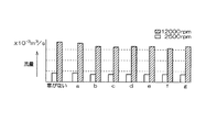
図4は、図3に示した従来のリヤ側ハウジングの冷却風吐出窓を塞いで風量を測定した結果を示す図である。図3に示すように、隣接する支持部520間で、回転子の回転方向上流側から下流側に向かって順番に配置されたそれぞれの冷却風吐出窓をa〜gとする。図4には、これらの冷却風吐出窓を一つずつ塞いだ場合の風量の変化が示されている。図4に示す測定結果によると、冷却性能に寄与しない冷却風吐出窓が存在することが分かった。具体的には、隣接する2つの支持部520の間に形成された7個の冷却風吐出窓a〜gのうち、最も回転方向上流側に配置された冷却風吐出窓aを塞いでも風量の変化はほとんど見られなかった。この測定結果から、図2に示す本実施形態のリヤ側ハウジング5のように、各冷却風吐出窓550を回転子2の回転方向下流側に寄せて配置することにより、冷却風吐出窓の数が減少することによる風量低下を抑制できることがわかる。
FIG. 4 is a diagram showing the result of measuring the air volume by closing the cooling air discharge window of the conventional rear housing shown in FIG. As shown in FIG. 3, the cooling air discharge windows arranged in order from the upstream side to the downstream side in the rotation direction of the rotor between the
図5は、本実施形態の車両用交流発電機1のファン騒音を測定した結果を示す図である。図5において、横軸は車両用交流発電機1の回転数を、縦軸はSPL(Sound Pressure Level)単位で表したファン騒音をそれぞれ示している。測定は、全ての次数成分を含む「オーバーオール」と、各次数成分の包絡線を示す「次数包絡」のそれぞれについて行った。なお、リブ530の幅を徐々に大から小に変化させた本実施形態のリヤ側ハウジング5を用いた場合の測定結果を実線で示すとともに、比較のために、傾斜はしているがリブ幅は等間隔にした従来形状のリヤ側ハウジング(図3)を用いた場合の測定結果を点線で示した。
FIG. 5 is a diagram showing a result of measuring fan noise of the vehicle alternator 1 of the present embodiment. In FIG. 5, the horizontal axis represents the rotational speed of the vehicle alternator 1, and the vertical axis represents fan noise expressed in SPL (Sound Pressure Level) units. The measurement was performed for each of “overall” including all the order components and “order envelope” indicating an envelope of each order component. The measurement result when using the rear housing 5 of the present embodiment in which the width of the
図5に示すように、車両用交流発電機1の回転数の低速から中速域において、「オーバーオール」および「次数包絡」の両方についてファン騒音低減の効果が確認された。特に、8000〜11000rpmの範囲においては大幅なファン騒音 の低減が実現された。 As shown in FIG. 5, the fan noise reduction effect was confirmed for both “overall” and “order envelope” in the low to medium speed range of the vehicle alternator 1. In particular, a significant reduction in fan noise was realized in the range of 8000 to 11000 rpm.
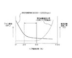
図6は、本実施形態の車両用交流発電機1のファン騒音と整流装置7の温度とをリブ530の幅の減少率をパラメータとして測定した結果を示す図である。図6において、横軸は各リブ530の幅を隣接するリブ530間でどの程度減少させるかを示すリブ幅の減少率(最も広いリブ幅530Aに対する最も狭いリブ幅530Dのリブ幅の減少率であって、(1−530D/530A)×100(%)で算出)を、縦軸は従来形状(図3)のリヤ側ハウジングを使用した車両用交流発電機を基準に示したファン騒音(実線)と整流装置温度(破線)をそれぞれ示している。
FIG. 6 is a diagram showing the results of measuring fan noise of the vehicle alternator 1 of this embodiment and the temperature of the rectifier 7 using the reduction rate of the width of the
図6に示すように、ファン騒音は、リブ幅の減少率が増すにしたがって減少し、ほぼ20%以上で減少の程度がなだらかになる。具体的には、リブ幅の減少率を20%以上に設定することにより、ファン騒音の「オーバーオール」が−3dB低減され、「次数包絡」が−2〜−4dBの範囲で低減された。一方、整流装置温度は、リブ幅の減少率が50%に達するまではほぼ一定であり、50%を超えると急激に上昇する。 As shown in FIG. 6, the fan noise decreases as the rib width reduction rate increases, and the degree of reduction becomes moderate at about 20% or more. Specifically, by setting the rib width reduction rate to 20% or more, the fan noise “overall” was reduced by −3 dB, and the “order envelope” was reduced in the range of −2 to −4 dB. On the other hand, the temperature of the rectifier is substantially constant until the rib width reduction rate reaches 50%, and rapidly increases when it exceeds 50%.
実際には、リブ530の幅の減少率を大きくするほど最も細いリブ530の幅が細くなって強度の面で実現が困難となるので、最小リブ幅を強度上の問題のない値にに決定した上で回転方向下流側に配置されたリブ530ほどリブ幅を徐々に増加させるといった設計手法になるが、この場合リブ幅の変化率が大きいほど冷却風吐出窓550の総面積が小さくなり整流装置7の温度が増加する傾向が見られたため、整流装置7の温度を抑えつつ騒音を低減させようとした場合には減少率は20%から50%に抑えることが望ましいと考えられる。
Actually, as the reduction rate of the width of the
このように、本実施形態の車両用交流発電機1では、リヤ側ハウジング5の支持部520間に周方向に配置される複数のリブ530を、従来構造のように等幅に設定するのではなく、回転子2の回転方向上流側から下流側に沿って徐々にリブ幅を小から大に変化させている。これにより、リブ530によって形成される冷却風吐出窓550の総面積は減少するが、総風量の減少を抑制することで整流装置7の温度上昇を抑えつつ、冷却風の圧力変動を各リブ530において徐変することによって(徐々に変化させることによって)リブ530付近で生じる耳障りな特定次数成分を抑制してファン騒音全体を低減することが可能になる。
As described above, in the vehicle alternator 1 of the present embodiment, the plurality of
また、隣り合うリブ530によって形成される冷却風吐出窓550の周方向幅を一定にすることにより、それぞれの冷却風吐出窓550を通して吐出される冷却風の風圧をほぼ均一にすることができるため、冷却風の乱れを抑制することができ、冷却風の乱れによって新たに発生するファン騒音や冷却性の低下を防止することができる。
Further, since the circumferential width of the cooling
また、複数のリブ530の周方向幅を、回転子2の回転方向上流から下流に向かって徐々に広くなるように設定することにより、特定次数のファン騒音を確実に低減することができる。
Further, by setting the circumferential widths of the plurality of
また、リヤ側ハウジング5のリブ530の幅を回転方向に沿って次第に広くすることにより、全てのリブ530を最小幅で形成した場合に比べて、整流装置7からリヤ側ハウジング5に伝わる伝熱量を増すことができるため、整流装置7の冷却性を向上させることができる。
Further, by gradually increasing the width of the
また、複数のリブ530の幅を、最大幅に対する最小幅の比率を0.8から0.5の範囲内に含まれるように設定することにより、ファン騒音低減と整流装置の温度低減の効果を両立させることが可能となる。特に、実験によると、リブ530の幅の減少率を35%から40%の範囲内(最大幅に対する最小幅の比率を0.65から0.6の範囲内)で設定することにより、整流装置7の温度上昇を抑えつつ良好なファン騒音の低減効果が得られることが確かめられている。
Further, by setting the width of the plurality of
また、リヤ側ハウジング5の隣接する支持部520の間において、複数のリブ530によって形成される冷却風吐出窓550は、図2に示すように、回転子2の回転方向下流側に偏在して配置されている。図4に示した冷却風量の測定から、回転方向上流になるほど冷却風吐出窓550がないことによる冷却風量への影響が少ないことがわかっているため、回転方向下流側に冷却風吐出窓550を偏在させることにより、冷却風量の確保による冷却性の維持が可能になる。
Also, between the
なお、本発明は上記実施形態に限定されるものではなく、本発明の要旨の範囲内において種々の変形実施が可能である。例えば、上述した実施形態では、リヤ側ハウジング5のリブ530および冷却風吐出窓550について本発明を適用したが、リヤ側ハウジング5の代わりにあるいはリヤ側ハウジング5とともにフロント側ハウジング4のリブおよび冷却風吐出窓について本発明を適用するようにしてもよい。
In addition, this invention is not limited to the said embodiment, A various deformation | transformation implementation is possible within the range of the summary of this invention. For example, in the embodiment described above, the present invention is applied to the
また、上述した実施形態では、リヤ側ハウジング5の複数のリブ530の周方向幅が、回転子2の回転方向上流から下流に向かって徐々に広くなるように設定したが、反対に、回転方向上流から下流に向かって徐々に狭くなるように設定してもよい。この場合にも同様に特定次数のファン騒音を確実に低減することができる。しかも、図4に示した実験結果から、一方の支持部520に近い回転方向上流側の冷却風吐出窓550を塞いでも冷却風量の低下が少ないことが確認されているため、回転方向上流側の方がリブ幅が広くなるようにすることで、冷却風量の低減を抑制して冷却性を維持することが可能になる。
In the above-described embodiment, the circumferential width of the plurality of
また、上述した実施形態では、支持部520間のリブ530の幅を徐々に幅を大から小に変化させたが、図3に示す構造において、支持部520間のリブ530で形成される冷却風吐出窓550を塞いだ場合と開けたままの風量を測定し変化率の低い窓(回転方向上流側に配置された冷却風吐出窓)は、整流装置7の温度上昇が問題ない範囲であれば塞いでも構わない。図7は、図3に示したリヤ側ハウジングの変形例を示す図である。図7に示すリヤ側ハウジング5Bは、図3に示したリヤ側ハウジング5Aにおいてaで示された冷却風吐出窓550が塞がれている。リブ幅が徐々に変化しているわけではないので冷却風の圧力変動を徐変することはできないが、リブ530で形成される各冷却風吐出窓550の総面積が減少することで、ファン騒音のオーバーオール値を低減することができる。現在市場に流通している製品の騒音を低減する場合には、この方法を採用することで、ハウジング成型型を一部を修正するだけで対応することができるため、ファン騒音対策を行った際の大幅なコスト上昇を抑えることができる利点もある。
In the above-described embodiment, the width of the
1 車両用交流発電機
2 回転子
3 固定子
4 フロント側ハウジング
5 リヤ側ハウジング
6 ブラシ装置
7 整流装置
8 電圧調整器
9 プーリ
510 ステー
520 支持部
530 リブ
550 冷却風吐出窓
DESCRIPTION OF SYMBOLS 1 Vehicle alternator 2 Rotor 3 Stator 4 Front side housing 5
Claims (4)
前記ハウジングは、前記固定子を支持するために用いられる複数の支持部を有しており、
前記ハウジングに形成された前記複数のリブの周方向側面は前記回転軸の径方向に対して傾斜しており、前記複数のリブは前記回転子の回転方向に沿って周方向幅が次第に変化し、
隣接する前記支持部の間において、前記複数のリブの周方向幅は、前記回転子の回転方向に沿って一方向に徐々に広く、あるいは、一方向に徐々に狭くなるように設定されていることを特徴とする車両用交流発電機。 A rotor that rotates integrally with the rotating shaft, a stator that is disposed opposite to the outer periphery of the rotor, and a rotating air that is rotated integrally with the rotating shaft to generate cooling air in a substantially radial direction of the rotating shaft. A cooling fan that cools the stator, a housing that accommodates the rotor and rotatably supports the rotating shaft, and a plurality of ribs that form a plurality of cooling air discharge windows in the circumferential direction. In a vehicle alternator comprising:
The housing has a plurality of support portions used to support the stator,
The circumferential side surfaces of the plurality of ribs formed in the housing are inclined with respect to the radial direction of the rotation shaft, and the circumferential width of the plurality of ribs gradually changes along the rotation direction of the rotor. ,
In between the support portions adjacent the circumferential width of the plurality of ribs are gradually increases in one direction along the rotational direction of the rotor, or it is configured so as to gradually decrease in one direction A vehicle alternator characterized by the above.
前記ハウジングは、整流装置が固定されるリヤ側ハウジングと、前記回転子が回転駆動されるプーリが取り付けられるフロント側ハウジングとに分割されており、
前記リヤ側ハウジングについて、前記複数のリブの周方向側面を前記回転軸の径方向に対して傾斜させるとともに、前記複数のリブの周方向幅を前記回転子の回転方向に沿って次第に変化させることを特徴とする車両用交流発電機。 In claim 1,
The housing is divided into a rear side housing to which the rectifier is fixed and a front side housing to which a pulley for rotating the rotor is attached.
In the rear housing, the circumferential side surfaces of the plurality of ribs are inclined with respect to the radial direction of the rotation shaft, and the circumferential width of the plurality of ribs is gradually changed along the rotation direction of the rotor. A vehicle alternator characterized by
前記複数のリブの幅は、最大幅に対する最小幅の比率が0.8から0.5の範囲内に含まれるように設定されていることを特徴とする車両用交流発電機。 In claim 1 or 2,
The width of the plurality of ribs is set so that the ratio of the minimum width to the maximum width is included in the range of 0.8 to 0.5.
隣接する前記支持部の間において、前記複数のリブによって形成される前記冷却風吐出窓は、前記回転子の回転方向下流側に偏在して配置されていることを特徴とする車両用交流発電機。 In any one of Claims 1-3,
The AC generator for vehicles, wherein the cooling air discharge window formed by the plurality of ribs is arranged unevenly on the downstream side in the rotation direction of the rotor between the adjacent support portions. .
Priority Applications (3)
| Application Number | Priority Date | Filing Date | Title |
|---|---|---|---|
| JP2005222599A JP4548264B2 (en) | 2005-08-01 | 2005-08-01 | Vehicle alternator |
| EP06015831A EP1750353B1 (en) | 2005-08-01 | 2006-07-28 | Vehicle-use generator with cooling air outlet windows of different widths |
| US11/494,639 US7619336B2 (en) | 2005-08-01 | 2006-07-28 | Vehicle-use generator with reduced fan noise |
Applications Claiming Priority (1)
| Application Number | Priority Date | Filing Date | Title |
|---|---|---|---|
| JP2005222599A JP4548264B2 (en) | 2005-08-01 | 2005-08-01 | Vehicle alternator |
Publications (2)
| Publication Number | Publication Date |
|---|---|
| JP2007043772A JP2007043772A (en) | 2007-02-15 |
| JP4548264B2 true JP4548264B2 (en) | 2010-09-22 |
Family
ID=37496704
Family Applications (1)
| Application Number | Title | Priority Date | Filing Date |
|---|---|---|---|
| JP2005222599A Expired - Fee Related JP4548264B2 (en) | 2005-08-01 | 2005-08-01 | Vehicle alternator |
Country Status (3)
| Country | Link |
|---|---|
| US (1) | US7619336B2 (en) |
| EP (1) | EP1750353B1 (en) |
| JP (1) | JP4548264B2 (en) |
Families Citing this family (3)
| Publication number | Priority date | Publication date | Assignee | Title |
|---|---|---|---|---|
| JP6706978B2 (en) * | 2016-06-23 | 2020-06-10 | 三菱電機株式会社 | Rotating electric machine for vehicle |
| CN110957842B (en) * | 2018-09-27 | 2023-10-20 | 株式会社电装 | Rotary electric machine |
| WO2024042561A1 (en) * | 2022-08-22 | 2024-02-29 | 三菱電機株式会社 | Rotary electric machine |
Citations (4)
| Publication number | Priority date | Publication date | Assignee | Title |
|---|---|---|---|---|
| JPH0779543A (en) * | 1993-07-15 | 1995-03-20 | Nippondenso Co Ltd | Electric rotating machine |
| JPH07107704A (en) * | 1993-10-06 | 1995-04-21 | Mitsubishi Electric Corp | Ac generator for vehicle |
| JPH09294353A (en) * | 1996-04-26 | 1997-11-11 | Denso Corp | Ac generator |
| WO2000016467A1 (en) * | 1998-09-11 | 2000-03-23 | Mitsubishi Denki Kabushiki Kaisha | Alternating current generator for vehicles |
Family Cites Families (28)
| Publication number | Priority date | Publication date | Assignee | Title |
|---|---|---|---|---|
| JP2750901B2 (en) | 1989-06-19 | 1998-05-18 | 桂川電機株式会社 | Color image forming equipment |
| US5399898A (en) * | 1992-07-17 | 1995-03-21 | Lsi Logic Corporation | Multi-chip semiconductor arrangements using flip chip dies |
| US5148265A (en) * | 1990-09-24 | 1992-09-15 | Ist Associates, Inc. | Semiconductor chip assemblies with fan-in leads |
| US5136365A (en) * | 1990-09-27 | 1992-08-04 | Motorola, Inc. | Anisotropic conductive adhesive and encapsulant material |
| JP2876773B2 (en) * | 1990-10-22 | 1999-03-31 | セイコーエプソン株式会社 | Program instruction word length variable type computing device and data processing device |
| US5173764A (en) * | 1991-04-08 | 1992-12-22 | Motorola, Inc. | Semiconductor device having a particular lid means and encapsulant to reduce die stress |
| US5477611A (en) * | 1993-09-20 | 1995-12-26 | Tessera, Inc. | Method of forming interface between die and chip carrier |
| US5366933A (en) * | 1993-10-13 | 1994-11-22 | Intel Corporation | Method for constructing a dual sided, wire bonded integrated circuit chip package |
| US5776796A (en) * | 1994-05-19 | 1998-07-07 | Tessera, Inc. | Method of encapsulating a semiconductor package |
| JP2917815B2 (en) * | 1994-06-07 | 1999-07-12 | 株式会社デンソー | Rotating electric machine |
| JP2616565B2 (en) * | 1994-09-12 | 1997-06-04 | 日本電気株式会社 | Electronic component assembly |
| DE19614580C2 (en) | 1995-04-14 | 2000-10-05 | Makita Corp | Ventilation device in a power tool |
| US5777379A (en) * | 1995-08-18 | 1998-07-07 | Tessera, Inc. | Semiconductor assemblies with reinforced peripheral regions |
| KR0182073B1 (en) * | 1995-12-22 | 1999-03-20 | 황인길 | Method of manufacturing semiconductor chip scale semiconductor package |
| KR100443484B1 (en) * | 1996-02-19 | 2004-09-18 | 마츠시타 덴끼 산교 가부시키가이샤 | Semiconductor device and method for fabricating the same |
| US5990545A (en) * | 1996-12-02 | 1999-11-23 | 3M Innovative Properties Company | Chip scale ball grid array for integrated circuit package |
| US6054337A (en) * | 1996-12-13 | 2000-04-25 | Tessera, Inc. | Method of making a compliant multichip package |
| US6057598A (en) * | 1997-01-31 | 2000-05-02 | Vlsi Technology, Inc. | Face on face flip chip integration |
| WO1998040915A1 (en) * | 1997-03-10 | 1998-09-17 | Seiko Epson Corporation | Electronic component and semiconductor device, method for manufacturing the same, circuit board have the same mounted thereon, and electronic equipment having the circuit board |
| JP3913903B2 (en) * | 1998-07-21 | 2007-05-09 | 三菱電機株式会社 | AC generator for vehicles |
| JP3951466B2 (en) | 1998-08-25 | 2007-08-01 | 株式会社デンソー | AC generator for vehicles |
| JP4769997B2 (en) * | 2000-04-06 | 2011-09-07 | ソニー株式会社 | THIN FILM TRANSISTOR AND ITS MANUFACTURING METHOD, LIQUID CRYSTAL DISPLAY DEVICE, LIQUID CRYSTAL DISPLAY DEVICE MANUFACTURING METHOD, ORGANIC EL DEVICE, AND ORGANIC EL DEVICE MANUFACTURING METHOD |
| JP3593038B2 (en) * | 2001-01-16 | 2004-11-24 | 三菱電機株式会社 | AC generator for vehicles |
| JP4118548B2 (en) * | 2001-11-06 | 2008-07-16 | 株式会社デンソー | Vehicle alternator |
| JP4055696B2 (en) * | 2003-11-04 | 2008-03-05 | 株式会社デンソー | AC generator for vehicles |
| FR2865080B1 (en) | 2003-12-19 | 2006-04-28 | Telma | SIMPLE RADIAL ELECTROMAGNETIC RETARDER COMPRISING MEANS FOR PROVIDING A VENTILATION |
| JP4123197B2 (en) * | 2004-06-28 | 2008-07-23 | 株式会社デンソー | AC generator for vehicles |
| JP4497090B2 (en) * | 2005-12-21 | 2010-07-07 | 株式会社デンソー | Vehicle alternator |
-
2005
- 2005-08-01 JP JP2005222599A patent/JP4548264B2/en not_active Expired - Fee Related
-
2006
- 2006-07-28 EP EP06015831A patent/EP1750353B1/en not_active Not-in-force
- 2006-07-28 US US11/494,639 patent/US7619336B2/en not_active Expired - Fee Related
Patent Citations (4)
| Publication number | Priority date | Publication date | Assignee | Title |
|---|---|---|---|---|
| JPH0779543A (en) * | 1993-07-15 | 1995-03-20 | Nippondenso Co Ltd | Electric rotating machine |
| JPH07107704A (en) * | 1993-10-06 | 1995-04-21 | Mitsubishi Electric Corp | Ac generator for vehicle |
| JPH09294353A (en) * | 1996-04-26 | 1997-11-11 | Denso Corp | Ac generator |
| WO2000016467A1 (en) * | 1998-09-11 | 2000-03-23 | Mitsubishi Denki Kabushiki Kaisha | Alternating current generator for vehicles |
Also Published As
| Publication number | Publication date |
|---|---|
| EP1750353A3 (en) | 2008-01-16 |
| US20070024128A1 (en) | 2007-02-01 |
| JP2007043772A (en) | 2007-02-15 |
| EP1750353A2 (en) | 2007-02-07 |
| US7619336B2 (en) | 2009-11-17 |
| EP1750353B1 (en) | 2012-04-11 |
Similar Documents
| Publication | Publication Date | Title |
|---|---|---|
| JP3279258B2 (en) | AC generator for vehicles | |
| US5952749A (en) | Cooling arrangement of alternator | |
| JPS62221839A (en) | Ac generator for motor car | |
| US20100283336A1 (en) | Ventilating system for electrical rotating electrical machines equipped with a forced-fluid flow cooling device and rotating electrical machine comprising same | |
| JP2009148057A (en) | Ac generator for vehicle | |
| CN107949979B (en) | AC generator for vehicle | |
| US6844638B2 (en) | Fan for rotating electric machine | |
| JP4670661B2 (en) | AC generator for vehicles | |
| JP4548264B2 (en) | Vehicle alternator | |
| JP3876912B2 (en) | AC generator for vehicles | |
| JP3294497B2 (en) | Alternator | |
| JP2008043026A (en) | Rotating electric machine for vehicle | |
| JP3982369B2 (en) | AC generator for vehicles | |
| JP4497090B2 (en) | Vehicle alternator | |
| JP4375456B2 (en) | AC generator for brushless vehicles | |
| JP3753093B2 (en) | Rotating electric machine for vehicles | |
| JP5211914B2 (en) | Rotating electric machine for vehicles | |
| JP3674211B2 (en) | Vehicle alternator | |
| JP3900677B2 (en) | AC generator for vehicles | |
| JPH05336704A (en) | Ac generator for vehicle | |
| EP0881753B1 (en) | Cooling arrangement of alternator | |
| JP2008061292A (en) | Vehicle ac generator | |
| JP2007104800A (en) | Rotating electric machine for vehicles | |
| JP2007060875A (en) | Ac generator for vehicle | |
| JP3644126B2 (en) | AC generator |
Legal Events
| Date | Code | Title | Description |
|---|---|---|---|
| A621 | Written request for application examination |
Free format text: JAPANESE INTERMEDIATE CODE: A621 Effective date: 20071017 |
|
| A977 | Report on retrieval |
Free format text: JAPANESE INTERMEDIATE CODE: A971007 Effective date: 20091113 |
|
| A131 | Notification of reasons for refusal |
Free format text: JAPANESE INTERMEDIATE CODE: A131 Effective date: 20091201 |
|
| A521 | Request for written amendment filed |
Free format text: JAPANESE INTERMEDIATE CODE: A523 Effective date: 20100126 |
|
| A131 | Notification of reasons for refusal |
Free format text: JAPANESE INTERMEDIATE CODE: A131 Effective date: 20100302 |
|
| A521 | Request for written amendment filed |
Free format text: JAPANESE INTERMEDIATE CODE: A523 Effective date: 20100429 |
|
| TRDD | Decision of grant or rejection written | ||
| A01 | Written decision to grant a patent or to grant a registration (utility model) |
Free format text: JAPANESE INTERMEDIATE CODE: A01 Effective date: 20100615 |
|
| A01 | Written decision to grant a patent or to grant a registration (utility model) |
Free format text: JAPANESE INTERMEDIATE CODE: A01 |
|
| A61 | First payment of annual fees (during grant procedure) |
Free format text: JAPANESE INTERMEDIATE CODE: A61 Effective date: 20100628 |
|
| R151 | Written notification of patent or utility model registration |
Ref document number: 4548264 Country of ref document: JP Free format text: JAPANESE INTERMEDIATE CODE: R151 |
|
| FPAY | Renewal fee payment (event date is renewal date of database) |
Free format text: PAYMENT UNTIL: 20130716 Year of fee payment: 3 |
|
| R250 | Receipt of annual fees |
Free format text: JAPANESE INTERMEDIATE CODE: R250 |
|
| R250 | Receipt of annual fees |
Free format text: JAPANESE INTERMEDIATE CODE: R250 |
|
| R250 | Receipt of annual fees |
Free format text: JAPANESE INTERMEDIATE CODE: R250 |
|
| R250 | Receipt of annual fees |
Free format text: JAPANESE INTERMEDIATE CODE: R250 |
|
| R250 | Receipt of annual fees |
Free format text: JAPANESE INTERMEDIATE CODE: R250 |
|
| R250 | Receipt of annual fees |
Free format text: JAPANESE INTERMEDIATE CODE: R250 |
|
| LAPS | Cancellation because of no payment of annual fees |