JP4543208B2 - Non-aqueous electrolyte battery device for artificial satellite - Google Patents
Non-aqueous electrolyte battery device for artificial satellite Download PDFInfo
- Publication number
- JP4543208B2 JP4543208B2 JP2000282460A JP2000282460A JP4543208B2 JP 4543208 B2 JP4543208 B2 JP 4543208B2 JP 2000282460 A JP2000282460 A JP 2000282460A JP 2000282460 A JP2000282460 A JP 2000282460A JP 4543208 B2 JP4543208 B2 JP 4543208B2
- Authority
- JP
- Japan
- Prior art keywords
- period
- battery
- state
- temperature
- flag
- Prior art date
- Legal status (The legal status is an assumption and is not a legal conclusion. Google has not performed a legal analysis and makes no representation as to the accuracy of the status listed.)
- Expired - Fee Related
Links
Images


Classifications
-
- Y—GENERAL TAGGING OF NEW TECHNOLOGICAL DEVELOPMENTS; GENERAL TAGGING OF CROSS-SECTIONAL TECHNOLOGIES SPANNING OVER SEVERAL SECTIONS OF THE IPC; TECHNICAL SUBJECTS COVERED BY FORMER USPC CROSS-REFERENCE ART COLLECTIONS [XRACs] AND DIGESTS
- Y02—TECHNOLOGIES OR APPLICATIONS FOR MITIGATION OR ADAPTATION AGAINST CLIMATE CHANGE
- Y02E—REDUCTION OF GREENHOUSE GAS [GHG] EMISSIONS, RELATED TO ENERGY GENERATION, TRANSMISSION OR DISTRIBUTION
- Y02E60/00—Enabling technologies; Technologies with a potential or indirect contribution to GHG emissions mitigation
- Y02E60/10—Energy storage using batteries
Description
【0001】
【発明の属する技術分野】
本発明は、人工衛星用非水電解質電池装置に関するものである。
【0002】
【従来の技術】
人工衛星には、通常は太陽電池と二次電池とが搭載されている。これら二種類の電池のうち太陽電池は、日照時(太陽光が太陽電池に照射されている時期)に人工衛星に電力を供給する。また、二次電池は、日照時には太陽電池によって充電されており、蝕時(例えば地球によって太陽光が遮られるために、太陽電池に太陽光が照射されない時期)には、人工衛星に電力を放電する。
【0003】
ところで、人工衛星に搭載される二次電池は、15年以上に渡って安定した充放電サイクルを維持することが要求されている。従来には、このような二次電池として、例えばニッケル水素電池が使用されており、日照期(太陽光が常に太陽電池に照射されている半年のうちの約138日間)には100%充電状態またはフロート状態による高い充電状態が保持されていた。一方、日陰期(1日に1度太陽光が地球の陰に隠れて太陽電池に照射されない時間を有する、半年のうちの約45日間)には、二次電池は人工衛星に電力を供給するために放電される。
【0004】
【発明が解決しようとする課題】
さて最近になって、人工衛星に搭載する二次電池に、リチウム電池を使用することが試みられている。ところが、リチウム電池とニッケル水素電池との性質の相違から、従来のニッケル水素電池と同じようにリチウム電池を充電貯蔵した場合には、リチウム電池の放電容量が小さくなってしまい、安定した充放電特性を発揮しにくいという問題があった。
【0005】
本発明は、上記した事情に鑑みてなされたものであり、その目的は、長期間に渡って安定した充放電特性を発揮できる人工衛星用非水電解質電池装置を提供することにある。
【0006】
【課題を解決するための手段】
上記の課題を解決するための、請求項1に記載の発明に係る人工衛星用非水電解質電池装置は、人工衛星に搭載された非水電解質電池と、前記非水電解質電池の温度を測定するための温度計測手段と、前記非水電解質電池を加熱または冷却するための加熱冷却手段と、前記温度計測手段で計測された温度をもとに前記加熱冷却手段を制御するための電池温度制御手段とを備えたものであって、人工衛星が日照期にあるときは前記非水電解質電池の管理温度を、日陰期の電池管理温度と同等あるいはそれ以下とし、したがって人工衛星が日陰期にあるときは前記非水電解質電池の管理温度を日照期の電池管理温度と同等あるいはそれ以上とするものである。日照期(約138日/半年)は日陰期(約45日/半年)に比べてきわめて長いため、この発明によれば電池が高温に維持される時間をきわめて短くでき、電池の劣化を抑制することができる。
【0007】
本発明の非水電解質電池装置では、人工衛星が日陰期にあるときは前記非水電解質電池の管理温度を10℃〜35℃とし、人工衛星が日照期にあるときは前記非水電解質電池の管理温度を−30℃〜10℃とする。
なお、これらの発明において、日陰期および日照期における電池の管理温度について述べると、できる限り速く電池がその管理温度になるように設定され、その管理温度範囲に電池温度が収まるように管理されるものではあるが、日陰期および日照期の入れ替わる時機には実際の電池温度の変化の遅れなどが発生することは当然起りうるものである。また、急速な放電などによって一時的に電池温度が前記管理温度の範囲を超えるなどの状況があっても、この発明の趣旨を逸脱しないことは言うまでもない。
【0008】
本発明の非水電解質電池装置において、さらに前記非水電解質電池の充放電状態を検出するための充放電状態検出手段と、前記非水電解質電池を充放電するための充放電手段と、前記充放電状態検出手段で検出された前記非水電解質電池の充放電状態に基づいて前記充放電手段を制御するための充放電制御手段とを備え、人工衛星が日陰期開始のときには前記非水電解質電池の管理充電状態が50%以上になるように制御し、人工衛星が日照期にあるときには前記非水電解質電池の管理充電状態が75%以下となるように制御することが好ましい。この発明によって、蝕時における電池の電力供給能力を確保するとともに、日照期において電池が長期にわたって高い充電状態におかれて劣化を早めることを避けることができる。
【0009】
本発明の非水電解質電池装置において、さらに人工衛星が日照期にあるときは前記非水電解質電池の管理充電状態を間欠充電により75%以下とするように制御することが好ましい。
上に述べた電池の管理充電状態は、できる限り速やかにその状態になるように設定され、制御されるものではあるが、日陰期および日照期の入れ替わる時機には実際の電池充電状態の変化の遅れなどが発生することは当然起りうるものである。また、何らかの要因で一時的に電池の充電状態が前記管理充電状態を外れることがあっても、この発明の趣旨を逸脱しないことは言うまでもない。
【0010】
【発明の作用、および発明の効果】
人工衛星に搭載された非水電解質電池では、蝕時には、人工衛星内の機器に電力を供給するように設定されているので、低温状態における内部抵抗の増大を回避すること、および高温状態における自己放電の増大を回避する必要がある。また、日照期には、高温における電池の劣化を回避するためになるべく低温に維持しておくとともに、非水電解質電池内部の凍結を回避することが必要である。このため、請求項1の発明では、日陰期には非水電解質電池の管理温度を、日照期と同等あるいはそれ以上とし、したがって人工衛星が日照期にあるときは前記非水電解質電池の管理温度を、日陰期と同等あるいはそれ以下とすることで、長期間の運用ができる。
【0011】
また、電池管理温度を、日陰期には10℃〜35℃に、日照期には−30℃〜10℃とすることが好ましい。理由は次に述べるとおりである。温度が10℃を下回り、例えば0℃になると電池のインピーダンスが大きくなるため、十分な電力供給が困難となる、また、電池の温度が35℃を越えて例えば45℃になると、電池の自己放電が大きくなったり、電池の劣化が高温により加速されるために電池の寿命が短くなる。一方、日照期の電池管理温度範囲を−30℃〜10℃としている理由は次に述べるとおりである。温度が−30℃を下回り、例えば−40℃になると電池の電解液が凝固するため、非常時の電力供給が困難となる、また、電池の温度が10℃を越えて例えば20℃になると、電池の劣化が加速されるために、15年以上にわたる電池寿命の確保が困難となる。なお、日陰期の電池管理温度として例えば20℃が許容される理由は、日照期に比べて日陰期が時間的にきわめて短いため、電池の劣化の不利よりも十分な電力供給の有利さが評価されるためである。 この発明によれば、日陰期においては、非水電解質電池の自己放電や電池劣化(内部抵抗の増大や容量の低下等)を押さえ、日照期には、非水電解質電池の凍結を回避しつつ、長期間にわたって安定した充放電状態を維持することができる。
【0012】
ところで、非水電解質電池は100%充電状態(満充電状態)あるいはこれに近い高い充電状態に長時間保持しておくと、放電容量が低下してしまうという性質がある。このため、高い充電状態の時間をなるべく短くしておくことが、非水電解質電池の安定した特性を保持するために重要な課題となる。請求項3の発明によれば、非水電解質電池の管理充電状態は、日陰期のときには50%以上とされ、日照期には75%以下とされている。このため、非水電解質電池を満充電しておく時間を短くすることができ、非水電解質電池の寿命を長く確保することが可能となる。
【0013】
なお、日陰期のときの非水電解質電池の実際の充電状態は、好ましくは、75%〜100%がよく、さらに好ましくは、90%〜100%がよい。また、日照期のときの非水電解質電池の充電状態は、好ましくは、10%〜60%がよく、さらに好ましくは30%〜50%がよい。
【0014】
また、日照期には、従来の二次電池に使用されていたフロート状態で充電またはトリクル充電を止め、間欠充電によって充電し、管理充電状態に制御するようにすると、非水電解質電池の長寿命化にさらに寄与できる。
【0015】
【発明の実施の形態】
次に本発明の一実施形態について、図1〜図11を参照しつつ、詳細に説明する。
図1には、本実施形態の人工衛星用リチウム電池装置(以下、「リチウム電池装置」と言う。)1を搭載した人工衛星2を示した。人工衛星2の本体部3からは、それぞれ対向する位置に一対の太陽電池4が設けられている。両太陽電池4は、人工衛星2の電力源として働くとともに、リチウム電池装置1の内部に備えられているリチウム電池5を充電するように接続されている(詳細については、後述する。)。また、人工衛星2には、地球E等との間でデータを送受信するためのアンテナ6が備えられている。
【0016】
人工衛星2は、図2に示すように、地球Eの静止衛星軌道Or上を周回している。地球Eが公転軌道上において、春分または秋分に近い時期にあるときには、人工衛星2は、所定の時間だけ地球Eの陰に隠れてしまい、図3に示すように、太陽電池4が太陽Sからの光を受けられない「蝕」の状態となる(なお、以後の記述において、太陽電池4に太陽光が照射されない時期を「蝕時」と言う。また、太陽電池4に太陽光が照射されている時期を「日照時」と言う)。
【0017】
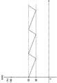
図4は、地球Eの一年の間に、人工衛星2に起こる蝕時の長さ(グラフにおいて「蝕時間」と記載した。)の変化を示したグラフである。地球Eが、春分または秋分に近くなると、蝕時が発生し、始めは数分の長さであったものが、だんだんと長くなり、春分・秋分の日には最大約70分となる。また、春分・秋分を過ぎると、蝕時の時間は対称的に短くなる。
【0018】
なお、以後の記述において、春分または秋分の時期において、人工衛星2に蝕時が発生する期間を「日陰期」と言う。人工衛星2が日陰期にあるときには、1日のうち、数分〜数十分の間は蝕時にあり、残りの20数時間は日照時となる。
また、地球Eが公転軌道上において、日陰期以外の地点にあるときには、人工衛星2は、常に(月の陰に隠れる等の特別な事情を除いて)日照時にある。この日陰期以外の期間を「日照期」と言う。
【0019】
次に、図5を参照しつつ、人工衛星2の電気的構成について説明する(なお図5は、電気的構成を模式的に示したものであり、必ずしも正確に表現されているわけではない。)。人工衛星2には、例えば軌道修正用のジェット噴射装置7やコンピュータ8等のように、電気によって駆動される電気駆動部材Aが備えられている(なお、図5中、コンピュータ8も電気駆動部材Aに含まれるが、図示の都合上、電気駆動部材Aの構成中から外してある)。電気駆動部材Aは、太陽電池4にスイッチ群Bを介して接続されており、日照時には太陽電池4から電気が供給されるようになっている。
【0020】
ここで、本実施形態におけるリチウム電池装置1の構成について説明する。リチウム電池装置1には、リチウム電池5と、このリチウム電池5の温度を測定する温度センサ9と、リチウム電池5の充電状態を測定する充電状態測定センサ10と、両センサ9,10からの信号を入力するように接続されているコンピュータ8と、リチウム電池5の温度を制御する温調装置11と、リチウム電池5を充電する充電用スイッチ12と、リチウム電池5と電気駆動部材Aとを接続する放電スイッチ13とが備えられている。
【0021】
リチウム電池5は、放電スイッチ13を介して電気駆動部材Aに接続されている。人工衛星2が日照時にあるときには、通常は放電スイッチ13は切断されている。
温調装置11は、リチウム電池5に熱を与えるヒータ(本発明における「加温装置」に該当する)11Aと、リチウム電池5から放熱させる放熱器11Bとから構成されている。また、充電状態測定センサ10は、リチウム電池5の電圧から充電状態を測定するように配設されている。
【0022】
次に、上記のように構成されたリチウム電池装置1を作動させるフローチャートについて説明する。
<リチウム電池の温度制御>
図6および図7を参照しつつ、リチウム電池5の温度を調節するフローチャートについて説明する。本実施形態では、リチウム電池5の管理温度は、日照期においては、−30℃〜10℃の範囲に、日陰期においては、10℃〜35℃の範囲となるように制御されている。
【0023】
まず、図6に示すように、コンピュータ8は、各フラグを初期条件に設定する(S10)。ここでは、リチウム電池5の充電状態(以下では、「SOC」と言うことがある。)を制御するためのフラグF1,F2,F3(詳細については、充電状態制御フローチャートにおいて説明する。)と、リチウム電池5の温度を制御するためのフラグC1,C2,C3とを初期値(全て「0」である)にする。
【0024】
フラグC1〜C3のうち、フラグC1は、人工衛星2の状態を示すものであり、「0」のときには日照期にあり、「1」のときには日陰期にある。また、フラグC2は、ヒータ11Aの状態を示すものであり、「0」のときには停止状態にあり、「1」のときには運転状態にある。また、フラグC3は、放熱器11Bの状態を示すものであり、「0」のときには停止状態にあり、「1」のときには運転状態にある。
【0025】
次に、図7に示した温度制御処理ルーチンについて説明する。このルーチンは、コンピュータ8が実行するメインルーチン(図示せず)から、所定の時間間隔で呼び出されるものである。
まず、人工衛星2が、日照期と日陰期とのいずれにあるかを示す状態フラグC1のチェックを行う(S20)。なお、本実施形態では、太陽電池4による発電が行われている場合には、日照期にあると判断され、太陽電池4による発電が行われていない場合には、日陰期にあると判断されるようになっている。
【0026】
<日陰期における温度調節手順>
ステップ20において、フラグC1が1であったとき(日陰期)には、日照期が始まったか否かが判定され(S30)、NOの場合には、ステップ70以下の日陰期における温度調節が行われる。なお、以下の手順は、ステップ20においてフラグC1が0であり、ステップ50において日陰期が開始されたと判断されて、ステップ60でフラグC1が1に変更されたとき(日照期から日陰期への変更時期である。)にも実行される。
【0027】
まず、ステップ70では、温度センサ9から入力されるリチウム電池5の温度tが、10℃以下であるか否かが判断される。温度tが10℃以下であったときには、ステップ80で、フラグC3の状態がチェックされる。ここでフラグC3が1の場合には、放熱器11Bの運転を停止し(S90)、フラグC3を0にした後(S100)、ステップ110に進む。また、ステップ80でフラグC3が0の場合には、そのままステップ110に進み、ヒータ11Aを運転状態として、フラグC2を1とした後(S120)、メインルーチンに戻る。こうして、温度tが10℃以下の場合には、放熱器11Bが停止状態となり、ヒータ11Aが運転状態となる。
【0028】
一方、ステップ70において、温度tが10℃より大きい場合には、ステップ130において温度tが35℃以上であるか否かが判断される。ここで、温度tが35℃よりも低い場合には、そのままメインルーチンに戻る。また、温度tが35℃以上であった場合には、ステップ140で、フラグC2が1であるか否かが判断される。フラグC2が1であったときには、ヒータ11Aの運転を停止し(S150)、フラグC2を0とした後(S160)にステップ170に進む。一方、ステップ140で、フラグC2が0であった場合には、放熱器11Bの運転を開始し(S170)、フラグC3を1としてから(S180)メインルーチンに戻る。こうして、温度tが35℃以上の場合には、ヒータ11Aが停止状態となり、放熱器11Bが運転状態となる。
以上のようにして、日陰期においては、リチウム電池5の温度tは、10℃〜35℃の範囲に調節される。
【0029】
<日照期における温度調節手順>
一方、ステップ20で、状態フラグC1が0であった場合(日照期)には、ステップ50において、日陰期が開始されていないことを条件として、ステップ190以下の日照期における温度調節が行われる。なお、以下の手順は、ステップ30において日照期が開始されたと判断されて、ステップ40でフラグC1が0に変更されたとき(日陰期から日照期への変更時期である。)にも実行される。
【0030】
まず、ステップ190では、温度センサ9から入力されるリチウム電池5の温度tが、−30℃以下であるか否かが判断される。温度tが−30℃以下であったときには、ステップ80で、フラグC3の状態がチェックされる。ここでフラグC3が1の場合には、放熱器11Bの運転を停止し(S90)、フラグC3を0にした後(S100)、ステップ110に進む。また、ステップ80でフラグC3が0の場合には、そのままステップ110に進み、ヒータ11Aを運転状態として、フラグC2を1とした後(S120)、メインルーチンに戻る。こうして、温度tが−30℃以下の場合には、放熱器11Bが停止状態となり、ヒータ11Aが運転状態となる。
【0031】
一方、ステップ190において、温度tが−30℃より大きい場合には、ステップ200において温度tが10℃以上であるか否かが判断される。ここで、温度tが10℃よりも低い場合には、そのままメインルーチンに戻る。また、温度tが10℃以上であった場合には、ステップ140で、フラグC2が1であるか否かが判断される。フラグC2が1であったときには、ヒータ11Aの運転を停止し(S150)、フラグC2を0とした後(S160)にステップ170に進む。一方、ステップ140で、フラグC2が0であった場合には、放熱器11Bの運転を開始し(S170)、フラグC3を1としてから(S180)、メインルーチンに戻る。こうして、温度tが10℃以上の場合には、ヒータ11Aが停止状態となり、放熱器11Bが運転状態となる。
以上のようにして、日照期においては、リチウム電池5の温度tは、−30℃〜10℃の範囲に調節される。
【0032】
<リチウム電池の充電状態制御手順>
次に、図8〜図11を参照しつつ、リチウム電池5の充電状態(State Of Charge)を制御する手順について説明する。図8は、地球Eが公転周期上において、日照期の位置にある場合の充電状態の推移を示している。この位置では、原則として日照時のみが続いている。後述のように、リチウム電池5は、30%〜50%の充電状態を維持するように調節されている。なおこのときには、リチウム電池5は、従来の二次電池のようにフロート状態での充電またはトリクル充電ではなく、充電状態が30%にまで低下したときに、間欠的に50%となるまで充電する方式を採用している。
【0033】
また、図9は、地球Eが日陰期にある場合のリチウム電池5の充電状態の推移を示している。このとき、日照時の一部においては、上記の日照期と同様にリチウム電池5は、30%〜50%の充電状態を維持するように間欠的な充電が行われている(以下、この時期を「間欠充電期」と言う)。蝕時になると、リチウム電池5の放電が開始され、人工衛星2の電力を供給する(以下、この時期を「放電期」と言う)。その後、日照時が始まると、50%以上の充電状態となるまで充電された後、再び間欠充電期となる。
【0034】
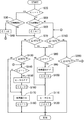
次に、図6、図10および図11を参照しつつ、リチウム電池5の充電状態制御フローチャートについて説明する。
まず、図6に示すように、コンピュータ8は、各フラグを初期条件に設定する(S10)。ここでは、リチウム電池5の充電状態(以下では、「SOC」と言うことがある)を制御するためのフラグF1,F2,F3(初期値は、全て「0」である)の内容について説明する。
フラグF1〜F3のうち、フラグF1は、リチウム電池5の状態を示すものである。フラグF1は、「0」、「1」または「2」のいずれかの数値をとり、「0」のときには間欠充電期に、「1」のときには充電期に、「2」のときには放電期にあることを示している。また、フラグF2は、充電用スイッチ12の状態を示すものであり、「0」のときには充電停止状態にあり、「1」のときには充電状態にあることを示している。また、フラグF3は、放電スイッチ13の状態を示すものであり、「0」のときには切り離された状態にあり、「1」のときには放電している状態にあることを示している。
【0035】
次に、図10および図11に示した充電状態制御処理ルーチンについて説明する。このルーチンは、コンピュータ8が実行するメインルーチン(図示せず)から、所定の時間間隔で呼び出されるものである。
まず、リチウム電池5が、いずれの時期にあるかを示す状態フラグF1のチェックが行われる(S300)。
フラグF1が0であったときには、図11に示すように、ステップ310において、日照期に至ったかどうかが判断される。なお、本実施形態では、この日照期は、予めプログラムされているフローチャート(図示せず)に従って、判断されるようになっているが、この他にも、例えば地上から充電開始信号を送信してもよい。
【0036】
<間欠充電期における充電状態制御手順>
まず、ステップ320では、フラグF2が1であるか否かが判断される。フラグF2が1であるとき(充電されているとき)には、ステップ360に進む。一方、フラグF2が0であるとき(充電されていないとき)には、ステップ330で、SOCが30%以下であるか否かが判断される。SOCが30%以下のときには、充電用スイッチ12が接続され(S340)、フラグF2が1とされた後(S350)、ステップ360に進む。また、ステップ330で、SOCが30%よりも大きいと判断されたときには、ステップ360で、SOCが50%以上であるか否かが判断される。
ステップ360において、SOCが50%よりも小さいと判断されたときには、そのままメインルーチンに戻る。一方、SOCが50%以上になっているときには、充電用スイッチ12を切断し(S370)、フラグF2を0とした後(S380)にメインルーチンに戻る。
こうして、間欠充電期においては、リチウム電池5は、間欠充電によってSOCが30%〜50%となるように制御されている。
【0037】
<日陰期の充電期における充電状態制御手順>
図10のフローチャートを実行したときには、ステップ420でフラグF1が1と判断された後、放電期(蝕時)が開始していないことを条件として(S430)、ステップ440からステップ500までの日陰期の充電期の処理が行われる。
ステップ440では、SOCが90%以上であるかどうかが判断され、YESのときにはそのままメインルーチンに戻る。一方、SOCが90%よりも小さいときには、ステップ450でフラグF2が1(充電状態)か否かが判断され、YESのときにはステップ480に進む。また、ステップ450でフラグF2が0のときには、充電用スイッチ12が接続され(S460)、フラグF2を1とした後に(S470)、ステップ480に進む。
【0038】
ステップ480では、SOCが100%以上であるか否かが判断されて、NOのときには充電状態を維持したままでメインルーチンに戻る。一方、SOCが100%に達しているときには、充電用スイッチ12を切断し(S490)、フラグF2を0として(S500)メインルーチンに戻る。
こうして、日陰期には、リチウム電池5は、充電状態が、90%〜100%のSOCとなるように制御されている。
【0039】
<放電期における充電状態制御手順>
次に、ステップ430において、放電期(蝕時)が開始されたと判断されたときの制御手順について説明する。このときには、フラグF1を2として(S510)、フラグF2の状態を判断する(S520)。フラグF2が0であったときには、ステップ550に進む。また、フラグF2が1のとき(充電状態)には、充電用スイッチ12を切断し(S530)、フラグF2を0とした後(S540)、ステップ550に進む。
ステップ550では、放電スイッチ13を接続して、フラグF3を1とした後(S560)にメインルーチンに戻る。
【0040】
放電期(F1=2)の間に、図10のルーチンが開始されたときには、ステップ300とステップ420からステップ570に進み、日照時(間欠充電期)が開始するまで放電期を維持する。一方、ステップ570で日照期が開始されたと判断されたときには、フラグF1を0として(S580)、放電スイッチ13を切断し(S590)、フラグF3を0とした後(S600)にメインルーチンに戻る。
こうして、放電期には、日照期が開始するまでリチウム電池5からの放電が続けられる。
【0041】
このように本実施形態によれば、リチウム電池5の温度は、日陰期には10℃〜35℃に、日照期には−30℃〜10℃に保持されるようにしてある。このため、日陰期においては、リチウム電池5の自己放電や電池劣化を押さえ、日照期には、リチウム電池5の凍結を回避しつつ自己放電の増大を押さえることができるので、長期間にわたって安定した充放電状態を維持することができる。
【0042】
また、リチウム電池5のSOCは、蝕時(放電期)開始のときには、90%〜100%となり得るようにされ、日照期(間欠充電期)には、30%〜50%に維持されている。このため、リチウム電池5を満充電しておく時間を短くすることができ、リチウム電池5の寿命を長く確保することが可能となる。
さらに、日照期には、従来の二次電池に使用されていたフロート状態で充電またはトリクル充電を止め、間欠充電によって充電するようにしたので、リチウム電池5の長寿命化にさらに寄与できる。
【0043】
なお、上記の実施形態において、「100%充電状態」とは、例えば0.2CAの充電電流とリチウム電池の最大許容充電電圧において、8時間の定電圧/定電流充電を行ったときの充電状態を言う。また、「0%充電状態」とは、100%充電状態から、リチウム電池の公称容量に相当する電気量を放電した状態、若しくは最低許容電圧まで放電したときの状態を言う。
【0044】
本発明の技術的範囲は、上記した実施形態によって限定されるものではなく、例えば、次に記載するようなものも本発明の技術的範囲に含まれる。その他、本発明の技術的範囲は、均等の範囲にまで及ぶものである。
(1)本実施形態では、放熱器11Bについて、停止または運転状態の制御を行っているが、本発明によれば、加熱冷却手段として加熱手段と冷却手段とに別々に設けた場合には、冷却手段を常に非水電解質電池に連結しておき、加熱手段のみの停止・運転状態の制御を行ってもよい。
(2)本実施形態において人工衛星2は静止衛星軌道上を周回しているが、本発明によれば、人工衛星は静止衛星軌道以外の軌道を周回していてもよい。
【図面の簡単な説明】
【図1】本実施形態における人工衛星の斜視図
【図2】人工衛星が地球軌道上を周回している様子を示す模式図
【図3】人工衛星が地球の陰に入っているとき(蝕)の様子を示す模式図
【図4】蝕時間の変化を示すグラフ
【図5】人工衛星における電気的構成を模式的に示すブロック図
【図6】リチウム電池の温度および充電状態の制御を行う初期条件設定ルーチン
【図7】リチウム電池の温度制御処理手順を示すフローチャート
【図8】日照期におけるリチウム電池の充電状態を示すグラフ
【図9】日陰期におけるリチウム電池の充電状態を示すグラフ
【図10】リチウム電池の充電状態制御処理手順を示すフローチャート(1)
【図11】リチウム電池の充電状態制御処理手順を示すフローチャート(2)
【符号の説明】
1…人工衛星用リチウム電池装置(人工衛星用非水電解質電池装置)
2…人工衛星
4…太陽電池(充放電手段)
5…リチウム電池(非水電解質電池)
8…コンピュータ(電池温度制御手段、充放電制御手段)
9…温度センサ(温度計測手段)
10…充電状態測定センサ(充放電状態検出手段)
11…温調装置(加熱冷却手段)
11A…ヒータ
11B…放熱器
12…充電用スイッチ(充放電手段)
13…放電スイッチ(充放電手段)
A…電気駆動部材(充放電手段)[0001]
BACKGROUND OF THE INVENTION
The present invention relates to a non-aqueous electrolyte battery device for artificial satellites.
[0002]
[Prior art]
An artificial satellite usually has a solar battery and a secondary battery. Of these two types of batteries, the solar battery supplies power to the artificial satellite during sunshine (time when sunlight is applied to the solar battery). In addition, the secondary battery is charged by the solar cell during sunshine, and when it is corroded (for example, when the solar cell is not irradiated with sunlight because it is blocked by the earth), power is discharged to the artificial satellite. To do.
[0003]
By the way, a secondary battery mounted on an artificial satellite is required to maintain a stable charge / discharge cycle for over 15 years. Conventionally, for example, a nickel metal hydride battery is used as such a secondary battery, and is 100% charged in the sunshine period (about 138 days of the half year in which sunlight is always radiated to the solar battery). Or the high charge state by the float state was hold | maintained. On the other hand, the secondary battery supplies power to the artificial satellite in the shade period (about 45 days of half a year, where sunlight is hidden behind the earth and is not irradiated to the solar cell once a day). Because of the discharge.
[0004]
[Problems to be solved by the invention]
Recently, it has been attempted to use a lithium battery as a secondary battery mounted on an artificial satellite. However, due to the difference in properties between the lithium battery and the nickel metal hydride battery, when the lithium battery is charged and stored in the same way as a conventional nickel metal hydride battery, the discharge capacity of the lithium battery becomes small, and stable charge / discharge characteristics are obtained. There was a problem that it was difficult to demonstrate.
[0005]
The present invention has been made in view of the above-described circumstances, and an object of the present invention is to provide a non-aqueous electrolyte battery device for an artificial satellite that can exhibit stable charge / discharge characteristics over a long period of time.
[0006]
[Means for Solving the Problems]
In order to solve the above problems, a non-aqueous electrolyte battery device for an artificial satellite according to the invention described in
[0007]
In the nonaqueous electrolyte battery device of the present invention,When the artificial satellite is in the shade period, the management temperature of the non-aqueous electrolyte battery is 10 ° C. to 35 ° C. When the artificial satellite is in the sunshine period, the management temperature of the non-aqueous electrolyte battery is −30 ° C. to 10 ° C. TossThe
In these inventions, the management temperature of the battery in the shade period and the sunshine period is described as follows. The battery is set to the management temperature as quickly as possible, and is managed so that the battery temperature falls within the management temperature range. However, it is a matter of course that a delay in the actual change in battery temperature may occur when the shade period and the sunshine period change. Needless to say, even if the battery temperature temporarily exceeds the control temperature range due to rapid discharge or the like, it does not depart from the spirit of the present invention.
[0008]
BookNonaqueous electrolyte battery device of the inventionIn addition,Charge / discharge state detection means for detecting the charge / discharge state of the non-aqueous electrolyte battery, charge / discharge means for charging / discharging the non-aqueous electrolyte battery, and the non-water detected by the charge / discharge state detection means Charge / discharge control means for controlling the charge / discharge means based on the charge / discharge state of the electrolyte battery, and when the artificial satellite starts the shade period, the management charge state of the non-aqueous electrolyte battery is 50% or more. And when the artificial satellite is in the sunshine period, the control charge state of the non-aqueous electrolyte battery is controlled to be 75% or less.Is preferred. According to the present invention, it is possible to secure the power supply capability of the battery at the time of corrosion, and to prevent the battery from being charged in a high charged state for a long period of time in the sunshine period and accelerating deterioration.
[0009]
BookNonaqueous electrolyte battery device of the inventionIn addition,When the artificial satellite is in the sunshine period, the management charge state of the non-aqueous electrolyte battery is controlled to 75% or less by intermittent charging.Is preferred.
The above-mentioned battery management charge state is set and controlled to reach that state as soon as possible, but the actual battery charge state changes at the time when the shade period and the sunshine period change. Of course, a delay or the like may occur. Needless to say, even if the state of charge of the battery temporarily deviates from the management charge state for some reason, it does not depart from the spirit of the present invention.
[0010]
Operation of the invention and effect of the invention
The non-aqueous electrolyte battery mounted on the satellite is set to supply power to the equipment in the satellite at the time of corrosion, so avoiding an increase in internal resistance in a low temperature state and self- It is necessary to avoid an increase in discharge. Further, during the sunshine period, it is necessary to keep the temperature as low as possible in order to avoid deterioration of the battery at high temperature, and to avoid freezing inside the nonaqueous electrolyte battery. For this reason, in the invention of
[0011]
Also,Battery management temperature from 10 ° C to 35 ° C during the shade period and -30 ° C to 10 ° C during the sunshine periodPreferably. The reason is as follows. When the temperature falls below 10 ° C., for example, 0 ° C., the impedance of the battery increases, so that sufficient power supply becomes difficult. When the temperature of the battery exceeds 35 ° C., for example, 45 ° C., the battery self-discharges. Or the deterioration of the battery is accelerated by the high temperature, so that the battery life is shortened. On the other hand, the reason why the battery management temperature range in the sunshine period is set to −30 ° C. to 10 ° C. is as follows. When the temperature is lower than −30 ° C., for example, −40 ° C., the electrolyte of the battery is solidified, making it difficult to supply power in an emergency, and when the temperature of the battery exceeds 10 ° C., for example, 20 ° C. Since the deterioration of the battery is accelerated, it is difficult to ensure the battery life over 15 years. The reason why the battery management temperature in the shaded period is allowed to be 20 ° C., for example, is that the shaded period is extremely short in time compared to the sunshine period, and thus the advantage of sufficient power supply is evaluated rather than the disadvantage of battery deterioration. It is to be done. According to the present invention, the self-discharge and battery deterioration (increase in internal resistance, decrease in capacity, etc.) of the nonaqueous electrolyte battery are suppressed in the shade period, and freezing of the nonaqueous electrolyte battery is avoided in the sunshine period. Thus, a stable charge / discharge state can be maintained over a long period of time.
[0012]
By the way, a non-aqueous electrolyte battery has a property that if it is kept for a long time in a 100% charged state (fully charged state) or a high charged state close to this, the discharge capacity is lowered. For this reason, it is an important subject to keep the high charge state time as short as possible in order to maintain the stable characteristics of the nonaqueous electrolyte battery. According to the invention of
[0013]
Note that the actual state of charge of the nonaqueous electrolyte battery during the shade period is preferably 75% to 100%, and more preferably 90% to 100%. In addition, the state of charge of the nonaqueous electrolyte battery during the sunshine period is preferably 10% to 60%, more preferably 30% to 50%.
[0014]
Also,DayDuring the lighting period, stop charging or trickle charging in the float state used for conventional secondary batteries, charge by intermittent charging, and control to the management charging stateThenThis can further contribute to the extension of the life of the nonaqueous electrolyte battery.
[0015]
DETAILED DESCRIPTION OF THE INVENTION
Next, an embodiment of the present invention will be described in detail with reference to FIGS.
FIG. 1 shows an
[0016]
As shown in FIG. 2, the
[0017]
FIG. 4 is a graph showing a change in the length of time of eclipse occurring in the
[0018]
In the following description, the period in which the
Further, when the earth E is in a point other than the shade period on the revolution orbit, the
[0019]
Next, the electrical configuration of the
[0020]
Here, the configuration of the
[0021]
The
The
[0022]
Next, a flowchart for operating the
<Temperature control of lithium battery>
A flowchart for adjusting the temperature of the
[0023]
First, as shown in FIG. 6, the computer 8 sets each flag as an initial condition (S10). Here, flags F1, F2, and F3 (details will be described in the charge state control flowchart) for controlling the state of charge of the lithium battery 5 (hereinafter sometimes referred to as “SOC”); Flags C1, C2, and C3 for controlling the temperature of the
[0024]
Among the flags C1 to C3, the flag C1 indicates the state of the
[0025]
Next, the temperature control processing routine shown in FIG. 7 will be described. This routine is called from a main routine (not shown) executed by the computer 8 at predetermined time intervals.
First, the state flag C1 indicating whether the
[0026]
<Temperature control procedure in the shade period>
In
[0027]
First, in
[0028]
On the other hand, if the temperature t is higher than 10 ° C. in
As described above, in the shade period, the temperature t of the
[0029]
<Temperature control procedure in sunshine period>
On the other hand, when the state flag C1 is 0 (sunshine period) in
[0030]
First, in
[0031]
On the other hand, if the temperature t is higher than −30 ° C. in
As described above, in the sunshine period, the temperature t of the
[0032]
<Lithium battery charge state control procedure>
Next, a procedure for controlling the state of charge of the
[0033]
FIG. 9 shows the transition of the state of charge of the
[0034]
Next, a charging state control flowchart of the
First, as shown in FIG. 6, the computer 8 sets each flag as an initial condition (S10). Here, the contents of flags F1, F2, and F3 (initial values are all “0”) for controlling the state of charge of lithium battery 5 (hereinafter sometimes referred to as “SOC”) will be described. .
Of the flags F <b> 1 to F <b> 3, the flag F <b> 1 indicates the state of the
[0035]
Next, the charge state control process routine shown in FIGS. 10 and 11 will be described. This routine is called at predetermined time intervals from a main routine (not shown) executed by the computer 8.
First, the status flag F1 indicating when the
When the flag F1 is 0, as shown in FIG. 11, it is determined in step 310 whether the sunshine period has been reached. In this embodiment, the sunshine period is determined according to a pre-programmed flowchart (not shown). In addition, for example, a charging start signal is transmitted from the ground. Also good.
[0036]
<Charge state control procedure in intermittent charge period>
First, in step 320, it is determined whether or not the flag F2 is 1. When the flag F2 is 1 (when charging), the routine proceeds to step 360. On the other hand, when the flag F2 is 0 (when the battery is not charged), it is determined at
If it is determined in
Thus, in the intermittent charging period, the
[0037]
<Charge state control procedure in the charging period in the shade>
When the flowchart of FIG. 10 is executed, after the flag F1 is determined to be 1 in
In
[0038]
In step 480, it is determined whether or not the SOC is 100% or more. If NO, the process returns to the main routine while maintaining the charged state. On the other hand, when the SOC reaches 100%, the charging
Thus, during the shade period, the
[0039]
<Charge state control procedure in discharge period>
Next, the control procedure when it is determined in step 430 that the discharge period (at the time of pitting) has started will be described. At this time, the flag F1 is set to 2 (S510), and the state of the flag F2 is determined (S520). When the flag F2 is 0, the process proceeds to step 550. When the flag F2 is 1 (charged state), the charging
In step 550, the
[0040]
When the routine of FIG. 10 is started during the discharge period (F1 = 2), the process proceeds from
Thus, in the discharge period, the discharge from the
[0041]
Thus, according to the present embodiment, the temperature of the
[0042]
Further, the SOC of the
Further, during the sunshine period, charging or trickle charging is stopped in the float state used for the conventional secondary battery, and charging is performed by intermittent charging, which can further contribute to the extension of the life of the
[0043]
In the above embodiment, the “100% charge state” means, for example, a charge state when a constant voltage / constant current charge is performed for 8 hours at a charge current of 0.2 CA and a maximum allowable charge voltage of a lithium battery. Say. Further, “0% charge state” refers to a state in which the amount of electricity corresponding to the nominal capacity of the lithium battery is discharged from the 100% charge state, or the state is discharged to the lowest allowable voltage.
[0044]
The technical scope of the present invention is not limited by the above-described embodiments, and, for example, those described below are also included in the technical scope of the present invention. In addition, the technical scope of the present invention extends to an equivalent range.
(1) In the present embodiment, the
(2) In this embodiment, the
[Brief description of the drawings]
FIG. 1 is a perspective view of an artificial satellite in the present embodiment.
FIG. 2 is a schematic diagram showing how an artificial satellite is orbiting the earth orbit.
FIG. 3 is a schematic diagram showing a state in which an artificial satellite is in the shade of the earth (erosion).
FIG. 4 is a graph showing changes in eclipse time.
FIG. 5 is a block diagram schematically showing the electrical configuration of an artificial satellite
FIG. 6 is an initial condition setting routine for controlling the temperature and charge state of a lithium battery.
FIG. 7 is a flowchart showing a temperature control processing procedure of the lithium battery.
FIG. 8 is a graph showing the state of charge of a lithium battery in the sunshine period
FIG. 9 is a graph showing the state of charge of a lithium battery in the shade period
FIG. 10 is a flowchart (1) showing the procedure for controlling the state of charge of a lithium battery.
FIG. 11 is a flowchart (2) showing the procedure for controlling the state of charge of the lithium battery.
[Explanation of symbols]
1. Lithium battery device for artificial satellite (non-aqueous electrolyte battery device for artificial satellite)
2. Artificial satellite
4 ... Solar cell (charging / discharging means)
5 ... Lithium battery (non-aqueous electrolyte battery)
8. Computer (battery temperature control means, charge / discharge control means)
9. Temperature sensor (temperature measurement means)
10: Charging state measuring sensor (charging / discharging state detecting means)
11 ... Temperature control device (heating and cooling means)
11A ... Heater
11B ... radiator
12 ... Charge switch (charging / discharging means)
13 ... Discharge switch (charging / discharging means)
A ... Electric drive member (charging / discharging means)
Claims (1)
人工衛星が日陰期にあるときは前記非水電解質電池の管理温度を10℃〜35℃とし、人工衛星が日照期にあるときは前記非水電解質電池の管理温度を−30℃〜10℃とすることを特徴とする人工衛星用非水電解質電池装置。A nonaqueous electrolyte battery mounted on an artificial satellite, a temperature measuring means for measuring the temperature of the nonaqueous electrolyte battery, a heating / cooling means for heating or cooling the nonaqueous electrolyte battery, and the temperature measuring means A non-aqueous electrolyte battery device for an artificial satellite comprising battery temperature control means for controlling the heating and cooling means based on the temperature measured in
When the artificial satellite is in the shade period, the management temperature of the nonaqueous electrolyte battery is 10 ° C. to 35 ° C., and when the artificial satellite is in the sunshine period, the management temperature of the nonaqueous electrolyte battery is −30 ° C. to 10 ° C. A nonaqueous electrolyte battery device for an artificial satellite.
Priority Applications (1)
| Application Number | Priority Date | Filing Date | Title |
|---|---|---|---|
| JP2000282460A JP4543208B2 (en) | 1999-09-17 | 2000-09-18 | Non-aqueous electrolyte battery device for artificial satellite |
Applications Claiming Priority (3)
| Application Number | Priority Date | Filing Date | Title |
|---|---|---|---|
| JP26441399 | 1999-09-17 | ||
| JP11-264413 | 1999-09-17 | ||
| JP2000282460A JP4543208B2 (en) | 1999-09-17 | 2000-09-18 | Non-aqueous electrolyte battery device for artificial satellite |
Publications (3)
| Publication Number | Publication Date |
|---|---|
| JP2001155783A JP2001155783A (en) | 2001-06-08 |
| JP2001155783A5 JP2001155783A5 (en) | 2007-10-25 |
| JP4543208B2 true JP4543208B2 (en) | 2010-09-15 |
Family
ID=26546500
Family Applications (1)
| Application Number | Title | Priority Date | Filing Date |
|---|---|---|---|
| JP2000282460A Expired - Fee Related JP4543208B2 (en) | 1999-09-17 | 2000-09-18 | Non-aqueous electrolyte battery device for artificial satellite |
Country Status (1)
| Country | Link |
|---|---|
| JP (1) | JP4543208B2 (en) |
Families Citing this family (8)
| Publication number | Priority date | Publication date | Assignee | Title |
|---|---|---|---|---|
| JP2006288150A (en) | 2005-04-04 | 2006-10-19 | Hitachi Koki Co Ltd | Charging device for lithium battery |
| FR2903822B1 (en) * | 2006-07-17 | 2008-10-03 | Somfy Sas | METHOD FOR OPERATING AN INSTALLATION COMPRISING A BATTERY INTENDED TO BE EXCLUSIVE LOADED BY A PHOTOVOLTAIC PANEL |
| KR100929036B1 (en) * | 2007-09-27 | 2009-11-30 | 삼성에스디아이 주식회사 | Protection circuit of battery pack, battery pack having same and operation method thereof |
| JP5392813B2 (en) * | 2008-10-31 | 2014-01-22 | 日産自動車株式会社 | Lithium-ion battery and its usage |
| JP5853696B2 (en) * | 2009-08-05 | 2016-02-09 | 株式会社Gsユアサ | Battery system |
| US9722334B2 (en) | 2010-04-07 | 2017-08-01 | Black & Decker Inc. | Power tool with light unit |
| RU2461102C1 (en) * | 2011-04-01 | 2012-09-10 | Открытое акционерное общество "Информационные спутниковые системы" имени академика М.Ф. Решетнёва" | Method for operation of lithium-ion accumulator battery in autonomous power supply system |
| US9368983B2 (en) * | 2011-12-15 | 2016-06-14 | The Boeing Company | Autonomous lithium-ion battery protection |
Citations (5)
| Publication number | Priority date | Publication date | Assignee | Title |
|---|---|---|---|---|
| JPH0530656A (en) * | 1990-12-14 | 1993-02-05 | Nec Corp | Satellite loading power supply system |
| JPH06121472A (en) * | 1992-10-08 | 1994-04-28 | Mitsubishi Electric Corp | Power unit |
| JPH09259939A (en) * | 1996-03-22 | 1997-10-03 | Nec Corp | On-satellite battery temperature control circuit |
| JPH10284133A (en) * | 1997-04-08 | 1998-10-23 | Sony Corp | Battery pack and its charging method |
| JP2001097295A (en) * | 1999-09-30 | 2001-04-10 | Mitsubishi Electric Corp | Temperature control device for spacecraft |
-
2000
- 2000-09-18 JP JP2000282460A patent/JP4543208B2/en not_active Expired - Fee Related
Patent Citations (5)
| Publication number | Priority date | Publication date | Assignee | Title |
|---|---|---|---|---|
| JPH0530656A (en) * | 1990-12-14 | 1993-02-05 | Nec Corp | Satellite loading power supply system |
| JPH06121472A (en) * | 1992-10-08 | 1994-04-28 | Mitsubishi Electric Corp | Power unit |
| JPH09259939A (en) * | 1996-03-22 | 1997-10-03 | Nec Corp | On-satellite battery temperature control circuit |
| JPH10284133A (en) * | 1997-04-08 | 1998-10-23 | Sony Corp | Battery pack and its charging method |
| JP2001097295A (en) * | 1999-09-30 | 2001-04-10 | Mitsubishi Electric Corp | Temperature control device for spacecraft |
Also Published As
| Publication number | Publication date |
|---|---|
| JP2001155783A (en) | 2001-06-08 |
Similar Documents
| Publication | Publication Date | Title |
|---|---|---|
| JP4668306B2 (en) | Secondary battery life estimation device and secondary battery life estimation method | |
| CA2284966A1 (en) | Lithium-ion battery charge control method | |
| US8283878B2 (en) | Battery storage device system, and motor driving body and moving body using the system | |
| JP2008283853A (en) | Method for charging battery of autonomic system | |
| US11431037B2 (en) | Method and system for fast-charging an electrochemical cell and fast-charging controller implemented in this system | |
| EP1091439B1 (en) | Non-aqueous electrolytic battery module for artificial satellite | |
| JP4543208B2 (en) | Non-aqueous electrolyte battery device for artificial satellite | |
| US6928381B2 (en) | Battery overtemperature control system and method | |
| JP2010086901A (en) | Deterioration diagnosing device and degradation diagnosing method of lithium secondary battery | |
| JPH09129268A (en) | Charging method for sealed nickel-cadmium cell | |
| JP2002151166A (en) | Method and device for temperature adjustment of secondary battery | |
| US20210384750A1 (en) | Method and device for controlling the level of charge of a traction battery of an electric vehicle | |
| US20130221906A1 (en) | Lithium Polymer Battery Charger and Methods Therefor | |
| KR20180031206A (en) | Battery management system and method for protecting a battery from over-discharge | |
| RU2543487C2 (en) | Operating method for nickel-hydrogen batteries in power supply system of spacecraft | |
| KR101975439B1 (en) | Underwater propulsion system using thermal batteries | |
| CN111337835B (en) | Method for automatically diagnosing discharge final voltage of hydrogen-nickel storage battery for satellite | |
| US7535202B2 (en) | Adjustable input pulsation device | |
| JP7180295B2 (en) | Vehicle charging control system | |
| JP2000278874A (en) | Charging of storage battery | |
| JP2017017778A (en) | Independent power supply device | |
| RU2401485C1 (en) | Preparation of nickel-hydrogen storage battery for standard operation on artificial earth satellite | |
| US11828806B2 (en) | Apparatus and method for calculating battery power | |
| JP4124460B2 (en) | Capacity estimation method for nickel metal hydride batteries | |
| JP2005235420A (en) | Life prediction method of nickel-hydrogen storage battery |
Legal Events
| Date | Code | Title | Description |
|---|---|---|---|
| A711 | Notification of change in applicant |
Free format text: JAPANESE INTERMEDIATE CODE: A712 Effective date: 20051213 |
|
| RD03 | Notification of appointment of power of attorney |
Free format text: JAPANESE INTERMEDIATE CODE: A7423 Effective date: 20060112 |
|
| RD04 | Notification of resignation of power of attorney |
Free format text: JAPANESE INTERMEDIATE CODE: A7424 Effective date: 20070110 |
|
| A521 | Written amendment |
Free format text: JAPANESE INTERMEDIATE CODE: A523 Effective date: 20070911 |
|
| A621 | Written request for application examination |
Free format text: JAPANESE INTERMEDIATE CODE: A621 Effective date: 20070911 |
|
| RD02 | Notification of acceptance of power of attorney |
Free format text: JAPANESE INTERMEDIATE CODE: A7422 Effective date: 20090914 |
|
| RD04 | Notification of resignation of power of attorney |
Free format text: JAPANESE INTERMEDIATE CODE: A7424 Effective date: 20090914 |
|
| A977 | Report on retrieval |
Free format text: JAPANESE INTERMEDIATE CODE: A971007 Effective date: 20100223 |
|
| A131 | Notification of reasons for refusal |
Free format text: JAPANESE INTERMEDIATE CODE: A131 Effective date: 20100225 |
|
| A521 | Written amendment |
Free format text: JAPANESE INTERMEDIATE CODE: A523 Effective date: 20100423 |
|
| A711 | Notification of change in applicant |
Free format text: JAPANESE INTERMEDIATE CODE: A712 Effective date: 20100507 |
|
| TRDD | Decision of grant or rejection written | ||
| A01 | Written decision to grant a patent or to grant a registration (utility model) |
Free format text: JAPANESE INTERMEDIATE CODE: A01 Effective date: 20100608 |
|
| RD02 | Notification of acceptance of power of attorney |
Free format text: JAPANESE INTERMEDIATE CODE: A7422 Effective date: 20100608 |
|
| A01 | Written decision to grant a patent or to grant a registration (utility model) |
Free format text: JAPANESE INTERMEDIATE CODE: A01 |
|
| A61 | First payment of annual fees (during grant procedure) |
Free format text: JAPANESE INTERMEDIATE CODE: A61 Effective date: 20100609 |
|
| FPAY | Renewal fee payment (event date is renewal date of database) |
Free format text: PAYMENT UNTIL: 20130709 Year of fee payment: 3 |
|
| R150 | Certificate of patent or registration of utility model |
Ref document number: 4543208 Country of ref document: JP Free format text: JAPANESE INTERMEDIATE CODE: R150 Free format text: JAPANESE INTERMEDIATE CODE: R150 |
|
| LAPS | Cancellation because of no payment of annual fees |