JP4541925B2 - Mounting panel and air conditioner - Google Patents
Mounting panel and air conditioner Download PDFInfo
- Publication number
- JP4541925B2 JP4541925B2 JP2005050624A JP2005050624A JP4541925B2 JP 4541925 B2 JP4541925 B2 JP 4541925B2 JP 2005050624 A JP2005050624 A JP 2005050624A JP 2005050624 A JP2005050624 A JP 2005050624A JP 4541925 B2 JP4541925 B2 JP 4541925B2
- Authority
- JP
- Japan
- Prior art keywords
- panel
- fixed
- extension
- extension panel
- duct
- Prior art date
- Legal status (The legal status is an assumption and is not a legal conclusion. Google has not performed a legal analysis and makes no representation as to the accuracy of the status listed.)
- Expired - Fee Related
Links
Images


Landscapes
- Duct Arrangements (AREA)
Description
本発明は、空気調和機のダクトを取付けるために、被空調室の壁開口に設けられる取付パネル及び空気調和機に関するものである。 The present invention relates to an attachment panel and an air conditioner provided at a wall opening of an air-conditioned room in order to attach a duct of an air conditioner.
空気調和機のダクトを被空調室の壁開口に開口又は挿通させるために、壁開口に固定パネルが設けられる。例えば、特許文献1には、空気調和機本体を窓枠に取付けるための据付装置が記載されている。特許文献1記載の据付装置は、取付枠と、内面に窓パネルが嵌着されたスライド枠とからなり、各々が上下スライド可能に嵌合連結されている。スライド枠の出し入れを調節することにより、窓枠の高さに応じて上下寸法調節可能となる。スライド枠の出し入れを調節して窓枠に固定した後、取付枠の枠開口に空気調和機本体が取り付けられる。
In order to open or insert the duct of the air conditioner into the wall opening of the air-conditioned room, a fixed panel is provided in the wall opening. For example,
しかしながら、取付枠からスライド枠の全体を引き出さない場合には、スライド枠の内面に嵌着された窓パネルの下方が、本体取付枠内の一部を覆ってしまい、取付枠に空気調和機本体を取付けるのに邪魔になってしまう。そのため、取付枠内に残った余分な窓パネルを切断しなければならず、手間がかかってしまう。 However, when the entire slide frame is not pulled out from the mounting frame, the lower part of the window panel fitted to the inner surface of the slide frame covers a part of the main body mounting frame, and the air conditioner main body is attached to the mounting frame. It gets in the way to install. Therefore, it is necessary to cut an extra window panel remaining in the mounting frame, which is troublesome.
そこで、本発明は、上記に鑑み、パネルを切断する必要が無く、簡単に壁開口に取り付けることのできる取付パネルを提供することを目的とするものである。 In view of the above, the present invention has an object to provide an attachment panel that can be easily attached to a wall opening without having to cut the panel.
上記目的を達成するため、本発明は、被空調室の壁開口に固定部材で固定され、空気調和機のダクトを取付けるための取付パネルであって、ダクトを取り付けるためのダクト取付口を有する固定パネルと、壁開口の大きさにあわせて固定パネルから延長パネルを突出できるように、固定パネルに沿ってスライド可能に設けられた延長パネルとからなることを特徴とする取付パネルである。 To achieve the above object, the present invention is fixed by a fixing member in the wall opening of the air conditioned room, a panel Mounting for attaching the duct of the air conditioner, having a duct mounting port for mounting the duct a fixed panel, so that it can protrude an extension panel from the fixed panel to fit the wall opening size, a mounting panel, characterized in that ing from an extension panel provided so as to be slidable along the fixed panel.
壁開口は、被空調室を囲む壁や天井等に形成された開口であって、空気調和機のダクトを室内外に挿通させたり、ダクトの一端を室内又は室外に開口させることができればよく、窓等の既存の開口を利用してもよい。壁開口の大きさは様々であるが、本発明の取付パネルは、固定パネルから延長パネルを出し入れ自在に突出可能であるので、延長パネルの出し入れ方向において壁開口の大きさに合わせることができる。 The wall opening is an opening formed in the wall or ceiling surrounding the air-conditioned room, as long as the duct of the air conditioner can be inserted indoors or outdoors, or one end of the duct can be opened indoors or outdoors, Existing openings such as windows may be used. Although the size of the wall opening varies, the mounting panel according to the present invention can project the extension panel from the fixed panel so that the extension panel can be taken in and out.
壁開口への取付パネルの固定は、ビス、ネジ、釘等の固定部材で固定されるが、これらに限定されるものではない。固定部材で直接、取付パネルに孔を開けながら壁開口の壁面に固定してもよいが、それでは開ける際に強い力が必要となるため、予め固定パネルに固定部材挿通用の孔を形成しておくのが好ましい。 The fixing of the mounting panel to the wall opening is fixed by a fixing member such as a screw, a screw, or a nail, but is not limited thereto. It may be fixed to the wall surface of the wall opening while directly making a hole in the mounting panel with the fixing member, but since this requires a strong force when opening, a hole for inserting the fixing member is formed in the fixing panel in advance. It is preferable to leave.
例えば、固定パネルの固定部と、固定部に沿って摺動する延長パネルの摺動部と、のうちいずれか一方に第1孔を形成し、他方に複数の第2孔をスライド方向に並んで形成し、第1孔のスライド方向の孔の長さを、隣接する第2孔の間隔よりも長く設定する。固定パネルの固定部とは、固定部材を用いて壁開口に固定される部分のことである。また、延長パネルの摺動部とは、固定部材の固定部と対向して摺動する部分のことであるが、摺動部の全体が固定部と接する必要はない。この固定部又は摺動部のいずれか一方に設けられた第1孔の孔の長さが、他方に設けられた第2孔の間隔よりも長いので、第1孔と、少なくとも1つの第2孔とが同一の位置になる。すなわち、延長パネルを固定パネルからどの程度突出させても、必ず第1孔と少なくとも1つの第2孔とが同一の位置になる。したがって、第1孔と第2孔とに、固定部材を挿入して壁穴に固定する場合に、固定パネルと延長パネルとの位置が限定されないですむので、無段階で延長パネルの出し入れを調節することができる。そのため、延長パネルを切断する必要がなくなる。 For example, a first hole is formed in one of the fixed portion of the fixed panel and the sliding portion of the extension panel that slides along the fixed portion, and a plurality of second holes are arranged in the sliding direction on the other side. The length of the hole in the sliding direction of the first hole is set longer than the interval between the adjacent second holes. The fixed portion of the fixed panel is a portion fixed to the wall opening using a fixing member. The sliding portion of the extension panel is a portion that slides facing the fixing portion of the fixing member, but the entire sliding portion does not need to be in contact with the fixing portion. Since the length of the first hole provided in either the fixed part or the sliding part is longer than the distance between the second holes provided in the other part, the first hole and at least one second The hole is in the same position. That is, no matter how much the extension panel protrudes from the fixed panel, the first hole and the at least one second hole are always in the same position. Therefore, when the fixing member is inserted into the first hole and the second hole and fixed to the wall hole, the position of the fixing panel and the extension panel is not limited. can do. Therefore, it is not necessary to cut the extension panel.
延長パネルは、複数設けられる。固定パネルにスライド可能に第1延長パネルを設け、さらに、第1延長パネルにスライド可能に第2延長パネルを設けるように、延長パネルを順々に連結していってもよいし、または、固定パネルにスライド可能に複数の延長パネルを設け、各延長パネルが互いにぶつからないように固定パネルに対しずらして配置するようにしてもよい。第1延長パネルにスライド可能に第2延長パネルを、第2延長パネルにスライド可能に第3延長パネルを、第3延長パネルにスライド可能に第4延長パネルをと、延長パネルを順々に連結していく場合は、固定パネルと第2延長パネルと第4延長パネルとを断面同一形状とし、第1延長パネルと第3延長パネルとを断面同一形状とすれば、それぞれ同一の金型を使用することができる。全体として2つの金型があればすむので好ましい。 A plurality of extension panels are provided. The extension panels may be sequentially connected or fixed so that the first extension panel is slidably provided on the fixed panel and the second extension panel is slidably provided on the first extension panel. A plurality of extension panels may be provided on the panel so as to be slidable, and the extension panels may be arranged so as to be shifted from the fixed panel so that the extension panels do not collide with each other. The second extension panel is slidable on the first extension panel, the third extension panel is slidable on the second extension panel, the fourth extension panel is slidable on the third extension panel, and the extension panels are connected in sequence. If the fixed panel, the second extension panel, and the fourth extension panel have the same cross section, and the first extension panel and the third extension panel have the same cross section, the same mold is used. can do. Since there are two molds as a whole, it is preferable.
本発明によると、固定パネルから延長パネルを出し入れ自在に突出可能であるので、延長パネルの出し入れを調節することにより、壁開口の大きさに合わせることができる。また、延長パネルは、固定パネルにスライド可能に設けられた第1延長パネルと、第1延長パネルにスライド可能に設けられた第2延長パネルとを備え、第2延長パネルは固定パネルと断面同一形状とされているので、それぞれ同一の金型を使用することができる。 According to the present invention, the extension panel can be protruded and retracted from the fixed panel so that it can be adjusted to the size of the wall opening by adjusting the extension panel. The extension panel includes a first extension panel slidably provided on the fixed panel and a second extension panel slidably provided on the first extension panel, and the second extension panel has the same cross section as the fixed panel. Since they are shaped, the same mold can be used.
以下、本発明の実施形態を図面に基づいて説明する。図1は本発明の取付パネルのカバー開放状態を示す(a)正面図、(b)A−A断面図、図2は本発明の取付パネルのカバー閉成状態を示す(a)正面図、(b)B−B断面図、図3は本発明の取付パネルの側面図、図4は同じく固定パネルの(a)C−C断面図、(b)正面図、(c)D−D断面図、(d)側面図、図5は同じく第1延長パネルの(a)E−E断面図、(b)正面図、(c)F−F断面図、(d)側面図、図6は同じく第2延長パネルの(a)G−G断面図、(b)正面図、(c)H−H断面図、(d)側面図、図7は同じくカバーパネルの(a)I−I断面図、(b)正面図、(c)J−J断面図、(d)側面図、図8は空気調和機のダクトの取付状態を示す図である。 Hereinafter, embodiments of the present invention will be described with reference to the drawings. 1A is a front view showing a cover open state of the mounting panel of the present invention, FIG. 2B is a cross-sectional view taken along the line A-A, and FIG. (B) BB sectional view, FIG. 3 is a side view of the mounting panel of the present invention, FIG. 4 is a (a) CC sectional view of the fixed panel, (b) Front view, (c) DD sectional view FIG. 5D is a side view of the first extension panel, and FIG. 5B is a front view of the first extension panel. FIG. 5B is a front view of the first extension panel. FIG. (A) GG sectional view of the second extension panel, (b) Front view, (c) HH sectional view, (d) Side view, FIG. 7 also shows (a) II section of the cover panel. Drawing, (b) Front view, (c) JJ sectional view, (d) Side view, FIG. 8 is a figure which shows the attachment state of the duct of an air conditioner.
本取付パネル1は、図1〜図3に示すように、固定パネル2と、固定パネル2の内面に沿ってスライド可能に設けられた延長パネル3及びカバーパネル4とからなり、被空調室の壁開口5を覆うように配される。カバーパネル4と延長パネル3とは、固定パネル2に対して内外にずらして配置され、スライド時に互いにぶつかることがない。
As shown in FIGS. 1 to 3, the
取付パネル1の壁開口5への固定は、ビス、ネジ、釘等の固定部材6で固定されるが、これらに限定されるものではない。固定部材6で直接、取付パネル1に孔を開けながら壁開口5の壁面に固定してもよいが、それでは開ける際に強い力が必要となるため、予め固定パネル2に固定部材6挿通用の孔が形成される。
The fixing of the
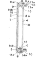
固定パネル2は、図3及び図4に示すように、壁開口5を覆う固定パネル背板7と、固定パネル背板7の上下端から室内側へ突出するように延設され、壁開口5の上下壁面に固定される固定部8と、上下の固定部8の内面に固定パネル背板7と並行に設けられた板状の第1レール9と、上下の固定部8の内端が幅狭となるようにクランク状に折曲した第2レール10とから構成され、これらは一体押出成型により形成される。第1レール9と第2レール10とは、固定パネル2に対して内外方向にずらした位置に形成される。
As shown in FIGS. 3 and 4, the
固定パネル背板7には、開口が形成され、ダクトaを取付けるためのダクト取付口11となる。ダクト取付口11の形状は、長方形に形成されるが、これに限定されるものではなく、取付けられるダクトaの形状によって変更すればよい。また、ダクト取付口11は、固定パネル背板7の一方に片寄って形成され、ダクト取付口11の一端から固定パネル背板7の一端までが、延長パネル3及びカバーパネル4を収容する延長パネル収容部12とされる。延長パネル収容部12側の一端から、延長パネル3を出し入れすることになる。
An opening is formed in the fixed
両方の固定部8には、固定部材6を挿通するための第1孔13が形成される。第1孔13は、延長パネル収容部12側に設けられ、スライド方向に長い長孔状に形成される。第1孔13の数は少なくとも1個あればよいが、複数形成してもよい。なお、延長パネル3を最大に飛び出させたときに対応するために、延長パネル3を出し入れする側の端に形成する。
Both
延長パネル3は、固定パネル2にスライド自在に設けられた第1延長パネル3aと、第1延長パネル3aにスライド自在に設けられた第2延長パネル3bとからなる。
The
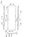
第1延長パネル3aは、図5に示すように、2本の脚14aで固定パネル2の固定部8内面を摺動する断面コ字状の摺動部14と、上下の摺動部14間を連結する延長パネル背板15とから構成され、第1延長パネル3aは全体として断面π字状に、一体押出成型により形成される。第1延長パネル3aのスライド方向の長さは、固定パネル2の一端からダクト取付口11の一端までの長さ、すなわち、延長パネル収容部12の長さと同一、またはそれよりも短く設定される。延長パネル収容部12に、第1延長パネル3aの全体をすっぽりと重ねることができる。また、第1延長パネル3aのスライド方向と垂直方向の長さは、固定パネル2の内径とほぼ同一とされ、固定パネル2の内面をスライド可能とされる。
As shown in FIG. 5, the
摺動部14は、2本の脚14aと、脚14aを連結する連結体14bとからなり、上下の摺動部14の外側の脚14aが、固定パネル2の背板7と第1レール9との間に挿入されることにより、第1延長パネル3aを固定パネル2内面に沿ってスライド可能となる。壁開口5の大きさにあわせて固定パネル2の側端から第1延長パネル3aを突出できる。また、上下の摺動部14の連結体14bには、取付時に固定部材6を挿通するための複数の第2孔16がスライド方向に並んで形成される。第2孔16の形状は、丸孔に形成されるが、長孔であってもよい。
The sliding
上記第1孔13の長孔の長さと、第2孔16の数とはそれぞれ限定されるものではないが、両者の関係が、「第1孔13のスライド方向の孔の長さ(L1)>隣接する第2孔16の間隔(L2)」であればよい。この関係であれば、第1延長パネル3aを固定パネル2からどの程度突出させても、必ず第1孔13と少なくとも1つの第2孔16とが同一の位置になる。したがって、第1孔13と第2孔16とに、固定部材6を挿入して壁開口5に固定する場合に、固定パネル2と第1延長パネル3aとの位置が限定されないので、無段階で第1延長パネル3aの出し入れを調節することができる。
The length of the long hole of the
なお、上記実施形態においては、固定パネル2の固定部8に第1孔13を、カバーパネル4及び第1延長パネル3aの摺動部14に第2孔16を形成したが、その逆、すなわち固定パネル2の固定部8に第2孔16を、第1延長パネル3aの摺動部14に第1孔13を形成してもよい。
In the above embodiment, the
第2延長パネル3bは、固定パネル2と断面同一形状とされ、図6に示されるような形状に形成される。固定パネル2と同一の金型を使用することができる。第2延長パネル3bには、固定パネル2の固定部8にあたる部分に、固定パネル2の第1孔13と同じ長孔状の孔3cが形成される。固定パネル2と第1延長パネル3aとを嵌合させてスライド可能とするのと同じように、第1延長パネル3aと第2延長パネル3bとを嵌合させ、第1延長パネル3aと第2延長パネル3bとを互いにスライド可能とする。第2延長パネル3bの孔3cと、第1延長パネル3aの第2孔とが重なり合った部分に固定部材6を挿通し、壁開口5の壁面に固定する。なお、固定パネル2に第2孔16を設けた場合は、第2延長パネル3bに設ける孔3cは、第1孔13のような長孔ではなく、第2孔16と同じ形状の孔にする。
The second extension panel 3b has the same cross-sectional shape as the fixed
カバーパネル4は、第1延長パネル3aと同一の金型を用いて形成される。すなわち、カバーパネル4は、固定パネル2の第2レール10を摺動する断面コ字状の摺動部17と、上下の摺動部17間を連結するカバーパネル背板18とから構成され、カバーパネル4は全体として断面π字状に形成される。カバーパネル4のスライド方向の長さは、延長パネル収容部12の長さと同一、またはそれよりも短く設定される。延長パネル収容部12に、第1延長パネル3aの全体をすっぽりと重ねることができる。また、固定パネル2のスライド方向と垂直方向の長さは、固定パネル2の内径とほぼ同一とされ、固定パネル2の内面をスライド可能とされる。
The
摺動部17は、2本の脚17aと、脚17aを連結する連結体17bとからなり、上下の摺動部17の外側の脚17aと内側の脚17aとで、固定パネル2の第2レール10のクランク部分を挟み込むことにより、カバーパネル4を固定パネル2内面に沿ってスライド可能となる。固定パネル2のダクト取付口11を覆いたい場合には、カバーパネル4をスライドさせれば、ダクト取付口11を覆うことができる。
The sliding
以上の構成の取付パネル1の取付方法を説明する。まず、取付パネル1を組み立てる。すなわち、固定パネル2の固定パネル背板7と第1レール9との間に、第1延長パネル3aの摺動部14の外側の脚14aを挿入するようにして、第1延長パネル3aを固定パネル2に嵌合させる。第1延長パネル3aは、固定パネル2の内面をスライド可能となる。同様にして、第1延長パネル3aと第2延長パネル3bとをスライド可能に嵌合させる。
A method of mounting the mounting
そして、カバーパネル4の上下の摺動部17の外側の脚17aと内側の脚17aとで、固定パネル2の第2レール10のクランク部分を挟み込むことにより、カバーパネル4を、固定パネル3よりも内側で、固定パネル2内面に沿ってスライド可能となる。
Then, by sandwiching the crank portion of the
次に、このように組み立てられた取付パネル1を、壁開口である窓枠5に載置する。窓は、上げ下げ窓、引き違い窓のいずれでもよい。この際、壁開口5の大きさが固定パネル2の大きさよりも大きい場合には、固定パネル2から第1延長パネル3aをスライドさせて飛び出させて、壁開口5の大きさに合わせる。また、固定パネル2の大きさと壁開口5の大きさとが同一である場合には、第1延長パネル3aを固定パネル2の延長パネル収容部12に重ねたままにしておく。このときは第2延長パネル3bは使用しない。
そして、第1延長パネル3aの摺動部14の第2孔16と、固定パネル2の固定部8の第1孔13とが重なっているところと、第1延長パネル3aの第2孔16と第2延長パネル3bの孔3cとが重なっているところに、ビスを挿入し、壁開口5の壁面に固定する。カバーパネル4は固定されていないので、スライド自在である。
Next, the mounting
And the
そして、図8に示すように、このようにして壁開口5に取り付けられた取付パネル1のダクト取付口11に、一体型空気調和機19のダクトaの開口端を固定する。一体型空気調和機19は、キャビネット20に、圧縮機21、凝縮器22、蒸発器23及び絞り機構(図示せず)が内装され、これらによって冷凍サイクルが形成される。そして、空気調和機19は、冷風を発生させて、室内を冷房する冷房運転を行う。そのため、空気調和機19は、蒸発器23に対する送風ファン24と、凝縮器22に対する排気ファン25と、排気用のダクトaと、冷房運転によって発生したドレン水を処理するためのポンプ26とを備えている。
And as shown in FIG. 8, the opening end of the duct a of the
ダクトaの一端は、空気調和機19の排気口27に連結され、ダクトaの他端は、壁開口5に取り付けられた取付パネル1に着脱可能に取り付けられる。すなわち、取付パネル1のダクト取付口11にダクトホルダ28が嵌め込まれ、ダクトホルダ28に、ダクトaの他端に設けられたダクトコネクタ29が着脱可能に装着される。ダクトコネクタ29がダクトホルダ28に装着されることにより、ダクトホルダ28は取付パネル1から抜けないように取り付けられる。ダクトホルダ28の室外側には、雨が入り込まないように、雨除け30が取り付けられている。したがって、ダクトコネクタ29をダクトホルダ28から外すことにより、ダクトaを取付パネル1から取り外すことができる。さらにダクトホルダ28も取付パネル1から取り外すことができる。
One end of the duct a is connected to the
なお、空気調和機は一体型のものに限定されるものではなく、室内機と室外機とからなる空気調和機であってもよく、ダクトaをダクト取付口11に挿通させる形態であってもよい。
Note that the air conditioner is not limited to an integrated type, and may be an air conditioner including an indoor unit and an outdoor unit, or may be a form in which the duct a is inserted through the
以上のように、本取付パネル1は、第1延長パネル3aを固定パネル2から飛び出し自在にスライド可能であるので、壁開口5の大きさに合わせることができる。また、第1延長パネル3aの長さが固定パネル2の延長パネル収容部12の長さと同一、またはそれよりも短く設定されているので、第1延長パネル3aを固定パネル2から突出させる必要の無い場合には、第1延長パネル3aの全体を延長パネル収容部12に重ねることができる。したがって、第1延長パネル3aが固定パネル2のダクト取付口11を覆うことがなく、第1延長パネル3aのどの部分も切断する必要がない。壁開口5への取付作業が容易である。
As described above, the mounting
固定部8に設けられた第1孔13の孔の長さが、摺動部14に設けられた第2孔16の間隔よりも長いので、第1孔13と少なくとも1つの第2孔16とが同一の位置になる。したがって、第1延長パネル3aを固定パネル2からどの程度突出させても、必ず第1孔13と少なくとも1つの第2孔16とが同一の位置になるので、固定パネル2と第1延長パネル3aとの位置が限定されない。そのため、無段階で第1延長パネル3aの出し入れを調節することができ、第1延長パネル3aを切断する必要がなくなる。
Since the length of the
さらにまた、本取付パネル1は、カバーパネル4を有するので、ダクト取付口11にダクトを取り付ける必要の無い場合には、カバーパネル4をスライド移動させて、ダクト取付口11を簡単に覆うことができる。したがって、ダクト取付口11が開口したままとならず、室外からの風雨の侵入を防止できる。また、カバーパネル4が固定パネル2に一体的に設けられているので、カバーパネル4が紛失してしまうこともない。
Furthermore, since the
また、カバーパネル4のスライド方向の長さが、固定パネル2の延長パネル収容部12の長さと同一、またはそれよりも短く設定されているので、ダクト取付口11を塞ぐ必要の無い場合には、カバーパネル4の全体をダクト取付口11の形成されていない延長パネル収容部12に重ねることができる。したがって、カバーパネル4がダクト取付口11を覆ってしまうことがない。カバーパネル4が不要なときはしまっておくことができ、必要なときにスライドさせてすぐに使用することができる。また、カバーパネル4と第1延長パネル3aとは、固定パネル2に対して内外にずれて配置されているので、スライドさせても互いにぶつかることがない。
In addition, since the length of the
なお、本発明は上記実施形態に限定されるものではなく、本発明の範囲内で上記実施形態に多くの修正及び変更を加え得ることは勿論である。例えば、上記実施形態においては、延長パネル3を第1延長パネル3aと第2延長パネル3bとから構成したが、第1延長パネル3aのみであってもよいし、または、第3延長パネル、第4延長パネル、第5延長パネルとさらに順々に連結していってもよい。この場合、第2延長パネル及び第4延長パネルを固定パネル2と同一金型で形成し、第3延長パネル及び第5延長パネルを第1延長パネル3aと同一金型とすればよい。全体として2つの金型があればすむ。
In addition, this invention is not limited to the said embodiment, Of course, many corrections and changes can be added to the said embodiment within the scope of the present invention. For example, in the above embodiment, the
また、上記実施形態では、複数の延長パネルを設ける場合に、固定パネル2に第1延長パネル3aを設け、その第1延長パネル3aにさらに第2延長パネル3bを設けたが、固定パネル2に、第1延長パネル3aと第2延長パネル3bとをスライド可能に設けてもよい。この場合、第1延長パネル3aと第2延長パネル3bとの断面を同一形状とし、第1延長パネル3を上記と同様にして固定パネルのレール8に嵌合させる。そして、第2延長パネル3bの摺動部14の2本の脚12aで、固定パネル2の第2レール10のクランク部分を挟み込むことにより、第2延長パネル3bを固定パネル2前面に沿ってスライド可能とする。第1延長パネル3と第2延長パネル3bとは、固定パネル2に対して内外にずれているので、スライドさせてもぶつからない。
In the above embodiment, when a plurality of extension panels are provided, the fixed
また、上記実施形態では、延長パネル3及びカバーパネル4を横方向にスライドさせたが、壁開口5の形状に合わせて上下方向にスライド可能としてもよい。また、本取付パネルは上下対称なので、上下反転させて使用することもでき、方向が限定されない。
In the above embodiment, the
また、カバーパネル4と延長パネル3とを兼用させてもよい。例えば、延長パネル3を伸縮可能とし、ダクトa取付時には、縮ませてダクト取付口11を覆わないようにし、ダクト取付不要時には、伸張させてダクト取付口11を覆うようにすればよい。延長パネル3を伸縮可能とする態様としては、延長パネル3を蛇腹状に形成すればよいが、これに限定されるものではない。
Further, the
1 取付パネル
2 固定パネル
3 延長パネル
4 カバーパネル
5 壁開口
6 固定部材
7 固定パネル背板
8 固定部
9 第1レール
10 第2レール
11 ダクト取付口
12 延長パネル収容部
13 第1孔
14 摺動部
15 延長パネル背板
16 第2孔
17 摺動部
18 延長パネル背板
DESCRIPTION OF
Claims (3)
前記延長パネルは、前記固定パネルにスライド可能に設けられた第1延長パネルと、該第1延長パネルにスライド可能に設けられた第2延長パネルとを備え、前記第2延長パネルは、前記固定パネルと断面同一形状とされたことを特徴とする取付パネル。 A mounting panel that is fixed to a wall opening of the air-conditioned room with a fixing member and is used to mount a duct of an air conditioner, and has a fixing panel having a duct mounting port for mounting the duct, and is adapted to the size of the wall opening. An extension panel provided to be slidable along the fixed panel so that the extension panel can protrude from the fixed panel.
The extension panel includes a first extension panel slidably provided on the fixed panel, and a second extension panel slidably provided on the first extension panel, and the second extension panel includes the fixed panel. A mounting panel characterized by having the same cross-sectional shape as the panel.
Priority Applications (1)
| Application Number | Priority Date | Filing Date | Title |
|---|---|---|---|
| JP2005050624A JP4541925B2 (en) | 2005-02-25 | 2005-02-25 | Mounting panel and air conditioner |
Applications Claiming Priority (1)
| Application Number | Priority Date | Filing Date | Title |
|---|---|---|---|
| JP2005050624A JP4541925B2 (en) | 2005-02-25 | 2005-02-25 | Mounting panel and air conditioner |
Publications (2)
| Publication Number | Publication Date |
|---|---|
| JP2006234300A JP2006234300A (en) | 2006-09-07 |
| JP4541925B2 true JP4541925B2 (en) | 2010-09-08 |
Family
ID=37042159
Family Applications (1)
| Application Number | Title | Priority Date | Filing Date |
|---|---|---|---|
| JP2005050624A Expired - Fee Related JP4541925B2 (en) | 2005-02-25 | 2005-02-25 | Mounting panel and air conditioner |
Country Status (1)
| Country | Link |
|---|---|
| JP (1) | JP4541925B2 (en) |
Families Citing this family (1)
| Publication number | Priority date | Publication date | Assignee | Title |
|---|---|---|---|---|
| CN105442283B (en) * | 2014-09-29 | 2023-07-07 | 青岛胶南海尔洗衣机有限公司 | Control panel device for clothes dryer and clothes dryer |
Citations (7)
| Publication number | Priority date | Publication date | Assignee | Title |
|---|---|---|---|---|
| JPS54178932U (en) * | 1978-06-07 | 1979-12-18 | ||
| JPS61124814U (en) * | 1985-01-24 | 1986-08-06 | ||
| JPH01130495U (en) * | 1988-02-22 | 1989-09-05 | ||
| JPH0234889U (en) * | 1988-08-31 | 1990-03-06 | ||
| JPH04225736A (en) * | 1990-12-26 | 1992-08-14 | Sanyo Electric Co Ltd | Air conditioner |
| JPH0510548A (en) * | 1991-07-02 | 1993-01-19 | Noritz Corp | Installation device for air-condiitoner |
| JPH10213345A (en) * | 1997-01-28 | 1998-08-11 | Nissei Kinzoku Kk | Room air conditioner mounting implement |
-
2005
- 2005-02-25 JP JP2005050624A patent/JP4541925B2/en not_active Expired - Fee Related
Patent Citations (7)
| Publication number | Priority date | Publication date | Assignee | Title |
|---|---|---|---|---|
| JPS54178932U (en) * | 1978-06-07 | 1979-12-18 | ||
| JPS61124814U (en) * | 1985-01-24 | 1986-08-06 | ||
| JPH01130495U (en) * | 1988-02-22 | 1989-09-05 | ||
| JPH0234889U (en) * | 1988-08-31 | 1990-03-06 | ||
| JPH04225736A (en) * | 1990-12-26 | 1992-08-14 | Sanyo Electric Co Ltd | Air conditioner |
| JPH0510548A (en) * | 1991-07-02 | 1993-01-19 | Noritz Corp | Installation device for air-condiitoner |
| JPH10213345A (en) * | 1997-01-28 | 1998-08-11 | Nissei Kinzoku Kk | Room air conditioner mounting implement |
Also Published As
| Publication number | Publication date |
|---|---|
| JP2006234300A (en) | 2006-09-07 |
Similar Documents
| Publication | Publication Date | Title |
|---|---|---|
| JP6343453B2 (en) | Embedded ceiling air conditioner | |
| KR20000073280A (en) | Window type air conditioner | |
| JP4541925B2 (en) | Mounting panel and air conditioner | |
| JP3071353B2 (en) | Indoor unit of air conditioner | |
| KR102273125B1 (en) | Air conditioner | |
| JP2006234299A (en) | Mounting panel and air conditioner | |
| KR20100051957A (en) | Indoor unit for air conditioning apparatus | |
| EP3330621A1 (en) | Indoor unit of air conditioner and method for assembling indoor unit of air conditioner | |
| JP3515206B2 (en) | Refrigerator electrical box | |
| JP6381886B2 (en) | Air conditioner | |
| JP2006132892A (en) | Air conditioner | |
| JP3166824U (en) | Shoji with louver | |
| CN215295164U (en) | Window type air conditioner | |
| KR102030525B1 (en) | Eco-friendly window system of apartment | |
| JP5195706B2 (en) | Fixed claw structure for wall-mounted indoor unit | |
| KR20090129198A (en) | Outdoor unit of air conditioner | |
| KR20040068815A (en) | Curtain assembly mounting structure for air conditioner | |
| KR200312147Y1 (en) | Structure of room air-conditioner | |
| JP2007163019A (en) | Indoor unit of air conditioner | |
| KR200228663Y1 (en) | Window Air Conditioners | |
| KR200153750Y1 (en) | Rear grill door apparatus of window type airconditioner | |
| KR200321117Y1 (en) | Structure covering for pipe hole of a wall type air-conditioner | |
| KR20020027863A (en) | The sealing apparatus for air-conditioner | |
| KR20230156640A (en) | Ventilation apparatus for windows with mounted guide | |
| KR100337904B1 (en) | Inlet grill structure with ribs for supporting and determination of assembly position |
Legal Events
| Date | Code | Title | Description |
|---|---|---|---|
| A621 | Written request for application examination |
Free format text: JAPANESE INTERMEDIATE CODE: A621 Effective date: 20070302 |
|
| A131 | Notification of reasons for refusal |
Free format text: JAPANESE INTERMEDIATE CODE: A131 Effective date: 20091110 |
|
| A521 | Written amendment |
Free format text: JAPANESE INTERMEDIATE CODE: A523 Effective date: 20091222 |
|
| A131 | Notification of reasons for refusal |
Free format text: JAPANESE INTERMEDIATE CODE: A131 Effective date: 20100323 |
|
| A521 | Written amendment |
Free format text: JAPANESE INTERMEDIATE CODE: A523 Effective date: 20100428 |
|
| TRDD | Decision of grant or rejection written | ||
| A01 | Written decision to grant a patent or to grant a registration (utility model) |
Free format text: JAPANESE INTERMEDIATE CODE: A01 Effective date: 20100601 |
|
| A01 | Written decision to grant a patent or to grant a registration (utility model) |
Free format text: JAPANESE INTERMEDIATE CODE: A01 |
|
| A61 | First payment of annual fees (during grant procedure) |
Free format text: JAPANESE INTERMEDIATE CODE: A61 Effective date: 20100624 |
|
| R150 | Certificate of patent or registration of utility model |
Free format text: JAPANESE INTERMEDIATE CODE: R150 |
|
| FPAY | Renewal fee payment (event date is renewal date of database) |
Free format text: PAYMENT UNTIL: 20130702 Year of fee payment: 3 |
|
| LAPS | Cancellation because of no payment of annual fees |