JP4537833B2 - Image forming system, image forming apparatus, control method, program, and recording medium - Google Patents
Image forming system, image forming apparatus, control method, program, and recording medium Download PDFInfo
- Publication number
- JP4537833B2 JP4537833B2 JP2004332301A JP2004332301A JP4537833B2 JP 4537833 B2 JP4537833 B2 JP 4537833B2 JP 2004332301 A JP2004332301 A JP 2004332301A JP 2004332301 A JP2004332301 A JP 2004332301A JP 4537833 B2 JP4537833 B2 JP 4537833B2
- Authority
- JP
- Japan
- Prior art keywords
- image forming
- forming apparatus
- printing
- mfp
- Prior art date
- Legal status (The legal status is an assumption and is not a legal conclusion. Google has not performed a legal analysis and makes no representation as to the accuracy of the status listed.)
- Expired - Fee Related
Links
- 238000000034 method Methods 0.000 title claims description 38
- 238000007639 printing Methods 0.000 claims description 186
- 238000004364 calculation method Methods 0.000 claims description 82
- 230000007704 transition Effects 0.000 claims description 76
- 238000004891 communication Methods 0.000 claims description 45
- 230000005764 inhibitory process Effects 0.000 claims description 23
- 230000001629 suppression Effects 0.000 claims description 22
- 230000004044 response Effects 0.000 claims description 11
- 230000002401 inhibitory effect Effects 0.000 claims description 8
- 230000015572 biosynthetic process Effects 0.000 claims description 3
- 230000006870 function Effects 0.000 description 50
- 238000010586 diagram Methods 0.000 description 33
- 238000012545 processing Methods 0.000 description 21
- 238000003860 storage Methods 0.000 description 11
- 230000000694 effects Effects 0.000 description 6
- 238000005259 measurement Methods 0.000 description 6
- 230000008569 process Effects 0.000 description 6
- 230000002093 peripheral effect Effects 0.000 description 5
- 230000005540 biological transmission Effects 0.000 description 3
- 238000003384 imaging method Methods 0.000 description 2
- 230000005012 migration Effects 0.000 description 2
- 238000013508 migration Methods 0.000 description 2
- 238000012805 post-processing Methods 0.000 description 2
- 238000004080 punching Methods 0.000 description 2
- 230000003068 static effect Effects 0.000 description 2
- 238000012546 transfer Methods 0.000 description 2
- 230000002776 aggregation Effects 0.000 description 1
- 238000004220 aggregation Methods 0.000 description 1
- 230000009849 deactivation Effects 0.000 description 1
- 238000005516 engineering process Methods 0.000 description 1
- 230000006872 improvement Effects 0.000 description 1
- 230000010365 information processing Effects 0.000 description 1
- 238000009434 installation Methods 0.000 description 1
- 238000003825 pressing Methods 0.000 description 1
Images


Classifications
-
- Y—GENERAL TAGGING OF NEW TECHNOLOGICAL DEVELOPMENTS; GENERAL TAGGING OF CROSS-SECTIONAL TECHNOLOGIES SPANNING OVER SEVERAL SECTIONS OF THE IPC; TECHNICAL SUBJECTS COVERED BY FORMER USPC CROSS-REFERENCE ART COLLECTIONS [XRACs] AND DIGESTS
- Y02—TECHNOLOGIES OR APPLICATIONS FOR MITIGATION OR ADAPTATION AGAINST CLIMATE CHANGE
- Y02D—CLIMATE CHANGE MITIGATION TECHNOLOGIES IN INFORMATION AND COMMUNICATION TECHNOLOGIES [ICT], I.E. INFORMATION AND COMMUNICATION TECHNOLOGIES AIMING AT THE REDUCTION OF THEIR OWN ENERGY USE
- Y02D10/00—Energy efficient computing, e.g. low power processors, power management or thermal management
Landscapes
- Accessory Devices And Overall Control Thereof (AREA)
- Control Or Security For Electrophotography (AREA)
Description
この発明は、複数台のデジタル複写機,プリンタ,ファクシミリ装置,デジタル複合機等の各画像形成装置を一括管理する管理装置(印刷管理サーバ)、その管理装置と共にそれと通信回線を介して接続可能なPC(パーソナルコンピュータ)等の端末装置および上記各画像形成装置とを備えた画像形成システム、上記管理装置における制御方法、上記管理装置のコンピュータ(CPU)に実行させるプログラム、およびそのプログラムを記録したコンピュータ読み取り可能な記録媒体に関する。 The present invention is a management device (printing management server) that collectively manages image forming apparatuses such as a plurality of digital copying machines, printers, facsimile machines, and digital multi-function machines, and can be connected to the management apparatus via a communication line. Image forming system including a terminal device such as a PC (personal computer) and each of the image forming apparatuses, a control method in the management apparatus, a program executed by a computer (CPU) of the management apparatus, and a computer recording the program The present invention relates to a readable recording medium.
従来、PC等の端末装置とデジタル複写機等の画像形成装置はケーブルによって1対1で直結され、端末装置では、例えばアプリケーション(アプリケーションソフトウェア)によってモニタ(表示装置)の画面上でキーボード等の操作に応じた文書データ(ドキュメントデータ)等の印刷データを生成(作成)し、キーボード等の操作によって印刷要求が発行された時に、プリンタドライバ(プリンタドライバプログラム)によって上記印刷データを上記画像形成装置が理解できる言語に翻訳(変換)し、その翻訳した印刷データおよび印刷条件を含む印刷依頼(印刷指示)を上記画像形成装置へ送信して印刷を行わせるようにしている。なお、アプリケーションはOS(オペレーティングシステム)によって管理されている。 Conventionally, a terminal device such as a PC and an image forming apparatus such as a digital copying machine are directly connected one-to-one by a cable. In the terminal device, for example, an operation of a keyboard or the like is performed on a monitor (display device) screen by an application (application software). Print data such as document data (document data) corresponding to the print data is generated (created), and when a print request is issued by an operation of a keyboard or the like, the image forming apparatus sends the print data to the printer driver (printer driver program). The document is translated (converted) into an understandable language, and a print request (print instruction) including the translated print data and print conditions is transmitted to the image forming apparatus to perform printing. The application is managed by an OS (Operating System).
しかし、ネットワーク等の通信回線の技術の需要が高まるにつれ、扱われるデータ量も増大していることから、その利用性,経済性等に対する要望が益々高まり、近年、それぞれ異なる機能を有する複数台の画像形成装置をネットワーク上に分散して接続し、選択的に利用可能にした画像形成システムが出回るようになった。
このような画像形成システムとしては、ネットワーク上に端末装置の他に複数台の各画像形成装置を一括管理する印刷管理サーバも接続することにより、端末装置からの印刷データを印刷管理サーバが各画像形成装置へ選択的に送信して印刷を行わせるようにしたものがある(例えば特許文献1参照)。
As such an image forming system, by connecting a print management server that collectively manages a plurality of image forming apparatuses in addition to the terminal apparatus on the network, the print management server receives the print data from the terminal apparatus. There is one that is selectively transmitted to a forming apparatus to perform printing (see, for example, Patent Document 1).
なお、アプリケーション(アプリ)とは、アプリケーション・ソフトウェア又はアプリケーション・プログラムのことを指す。このアプリケーションは、ユーザインタフェースを行う部分で、ユーザに提供する機能を実現するためのものであり、コピー機能を実現するためのアプリ(コピーアプリ)、プリンタ機能を実現するためのアプリ(プリンタアプリ)、スキャナ機能を実現するためのアプリ(スキャナアプリ)、FAX(ファクシミリ)機能を実現するためのアプリ(FAXアプリ)などがある。 The application (application) refers to application software or an application program. This application is a part that performs a user interface, and is for realizing a function provided to a user. An application for realizing a copy function (copy application) and an application for realizing a printer function (printer application) There are an application for realizing the scanner function (scanner application), an application for realizing the FAX (facsimile) function (FAX application), and the like.
しかしながら、上述した画像形成システムでは、印刷管理サーバが、複数台の画像形成装置の中からユーザが希望する印刷条件等の所要条件を確実に満たす画像形成装置を印刷に使用する機器(印刷使用機器)として選択することはできなかった。
この発明は、上記の点に鑑みてなされたものであり、画像形成システムを構成する複数台の画像形成装置の中から所要条件を確実に満たす画像形成装置を印刷に使用する機器として使用できるようにすることを目的とする。
However, in the above-described image forming system, the print management server uses a device (print using device) that uses for printing an image forming device that surely satisfies a required condition such as a printing condition desired by a user from among a plurality of image forming devices. ) Could not be selected.
The present invention has been made in view of the above points, and an image forming apparatus that reliably satisfies a required condition among a plurality of image forming apparatuses constituting an image forming system can be used as an apparatus used for printing. The purpose is to.
この発明は、上記の目的を達成するため、管理装置、その管理装置と共にそれと通信回線を介して接続可能な端末装置および画像形成装置とを備えた画像形成システム、上記管理装置における制御方法、その管理装置のコンピュータに実行させるプログラム、およびそのプログラムを記録したコンピュータ読み取り可能な記録媒体を提供する。 To achieve the above object, the present invention provides a management apparatus, an image forming system including the management apparatus and a terminal device and an image forming apparatus that can be connected to the management apparatus via a communication line, a control method in the management apparatus, A program to be executed by a computer of a management apparatus and a computer-readable recording medium on which the program is recorded are provided.
請求項1の発明による管理装置は、印刷データを生成する端末装置、および該端末装置からの上記印刷データを可視画像として印刷媒体への印刷を行う複数台の各画像形成装置が通信回線を介して接続され、上記端末装置からの上記印刷データを上記各画像形成装置へ選択的に送信して上記印刷を行わせる管理装置であって、上記端末装置から上記印刷データおよび所要条件を含む印刷依頼を受け、該所要条件が印刷条件の場合に、該印刷条件および上記各画像形成装置の現時点の電力モードに基づいて該各画像形成装置で上記印刷データの印刷によって消費される該各画像形成装置別の消費電力量をそれぞれ計算する消費電力量計算手段を有し、該手段による各計算結果に基づいて該各画像形成装置のいずれかを上記印刷に使用する機器として選択する機器選択手段と、上記消費電力量計算手段による各画像形成装置別の計算の開始前に、その計算対象の画像形成装置に対して電力モード移行の抑止を指示するモード移行抑止指示手段と、上記消費電力量計算手段による各画像形成装置別の計算結果に基づき前記機器選択手段により選択された画像形成装置に前記印刷依頼に係る印刷指示が送信された後、その計算対象の画像形成装置に対して電力モード移行の抑止解除を指示するモード移行抑止解除手段とを設け、上記機器選択手段が、上記所要条件が印刷条件と印刷スピードよりも省エネルギーを優先する機器選択条件とからなる場合に、上記消費電力量計算手段による各計算結果から最も消費電力量の少ない画像形成装置を上記印刷に使用する機器として選択するものである。 According to a first aspect of the present invention, there is provided a management apparatus comprising: a terminal device that generates print data; and a plurality of image forming apparatuses that print the print data from the terminal device on a print medium as a visible image via a communication line. A management apparatus that selectively transmits the print data from the terminal device to each of the image forming apparatuses to perform the printing, the print request including the print data and necessary conditions from the terminal device Each of the image forming apparatuses consumed by printing of the print data in each of the image forming apparatuses based on the printing conditions and the current power mode of each of the image forming apparatuses. A power consumption calculating means for calculating another power consumption, and a device that uses any one of the image forming apparatuses for the printing based on the calculation results by the means; A device selection means for selecting the mode, and a mode transition inhibition instruction means for instructing the image forming apparatus that is the calculation target to inhibit the transition of the power mode before the calculation for each image forming apparatus by the power consumption calculation means is started. And after the print instruction related to the print request is transmitted to the image forming apparatus selected by the device selection means based on the calculation result for each image forming apparatus by the power consumption calculating means, the image formation of the calculation target A mode transition inhibition canceling means for instructing the apparatus to cancel the suppression of power mode transition, and the device selection means includes the required conditions including a printing condition and a device selection condition that prioritizes energy saving over the printing speed. to, Monodea selecting fewer image forming apparatus most power consumption from the calculation result by the power consumption calculation unit as a device to be used in the printing .
請求項2の発明による管理装置は、請求項1の管理装置において、上記各画像形成装置からそれぞれ該画像形成装置の現時点の電力モードを示すプロパティを取得するプロパティ取得手段を設けたものである。
請求項3の発明による管理装置は、請求項1の管理装置において、上記各画像形成装置の現時点の電力モードを示すプロパティを登録するプロパティ登録手段を設けたものである。
請求項4の発明による管理装置は、請求項3の管理装置において、上記プロパティ登録手段が、上記各画像形成装置からそれぞれ通知されてくる該各画像形成装置の上記プロパティを登録するものである。
A management apparatus according to a second aspect of the present invention is the management apparatus according to the first aspect, further comprising property acquisition means for acquiring a property indicating the current power mode of the image forming apparatus from each of the image forming apparatuses.
According to a third aspect of the present invention, there is provided a management apparatus according to the first aspect, further comprising property registration means for registering a property indicating the current power mode of each of the image forming apparatuses.
According to a fourth aspect of the present invention, there is provided a management apparatus according to the third aspect , wherein the property registration unit registers the property of each image forming apparatus notified from each of the image forming apparatuses.
請求項5の発明による管理装置は、請求項3の管理装置において、上記プロパティ登録手段が、外部から入力される上記各画像形成装置別の上記プロパティを登録するものである。
請求項6の発明による管理装置は、請求項1〜5のいずれかの管理装置において、上記各画像形成装置別の消費電力量を計算するための該各画像形成装置別の計算プログラムをそれぞれ記憶する計算プログラム記憶手段を設け、上記消費電力量計算手段が、上記各画像形成装置別の計算プログラムに従って上記各画像形成装置別の消費電力量を計算するものである。
A management apparatus according to a fifth aspect of the invention is the management apparatus according to the third aspect , wherein the property registration means registers the property for each image forming apparatus input from the outside.
According to a sixth aspect of the present invention, there is provided a management apparatus according to any one of the first to fifth aspects, wherein the calculation program for each image forming apparatus for calculating the power consumption for each image forming apparatus is stored. Calculating power storage means for calculating the power consumption amount for each image forming apparatus in accordance with the calculation program for each image forming apparatus.
請求項7の発明による管理装置は、請求項6の管理装置において、上記端末装置から上記各画像形成装置別の上記計算プログラムを取得する計算プログラム取得手段を設けたものである。
請求項8の発明による管理装置は、請求項6の管理装置において、上記各画像形成装置からそれぞれ上記計算プログラムを取得する計算プログラム取得手段を設けたものである。
According to a seventh aspect of the present invention, there is provided a management apparatus according to the sixth aspect , further comprising: a calculation program acquisition unit that acquires the calculation program for each image forming apparatus from the terminal device.
According to an eighth aspect of the present invention, there is provided a management apparatus according to the sixth aspect , further comprising calculation program acquisition means for acquiring the calculation program from each of the image forming apparatuses.
請求項9の発明による画像形成システムは、請求項2の管理装置と上記端末装置と上記各画像形成装置とを上記通信回線を介して接続可能な画像形成システムにおいて、上記管理装置のプロパティ取得手段に、上記端末装置から上記印刷依頼を受けた場合に、上記各画像形成装置に対して該各画像形成装置の上記プロパティを要求する手段を備え、上記各画像形成装置にそれぞれ、上記管理装置から上記プロパティの要求を受けた場合に、自己の上記プロパティを上記管理装置へ通知するプロパティ通知手段と、上記管理装置から上記電力モード移行の抑止が指示されてから該抑止の解除が指示されるまで、自己の電力モードの移行を抑止するモード移行抑止手段とを設けたものである。 According to a ninth aspect of the present invention, there is provided an image forming system in which the management device of the second aspect , the terminal device, and the respective image forming devices can be connected via the communication line. And a means for requesting the image forming apparatus to request the property of the image forming apparatus when the print request is received from the terminal apparatus. When a request for the property is received, a property notification means for notifying the management device of its own property, and from the management device instructing suppression of the power mode transition until the cancellation of the suppression is instructed And a mode transition inhibiting means for inhibiting the transition of its own power mode.
請求項10の発明による画像形成システムは、請求項4の管理装置と上記端末装置と上記各画像形成装置とを上記通信回線を介して接続可能な画像形成システムにおいて、上記各画像形成装置にそれぞれ、所定のタイミングで自己の上記プロパティを上記管理装置へ通知するプロパティ通知手段と、上記管理装置から上記電力モード移行の抑止が指示されてから該抑止の解除が指示されるまで、自己の電力モードの移行を抑止するモード移行抑止手段とを設けたものである。
請求項11の発明による画像形成システムは、請求項10の画像形成システムにおいて、上記各画像形成装置のプロパティ通知手段がそれぞれ、当該画像形成装置の起動時に該画像形成装置の上記プロパティを上記管理装置へ通知するものである。
An image forming system according to a tenth aspect of the present invention is an image forming system in which the management apparatus according to a fourth aspect of the invention, the terminal device, and the image forming apparatuses can be connected via the communication line. Property notification means for notifying the management device of the property of its own at a predetermined timing, and its own power from when the management device is instructed to suppress the transition to the power mode until the cancellation of the suppression is instructed. Mode transition inhibiting means for inhibiting mode transition is provided.
The image forming system according to the invention of
請求項12の発明による画像形成システムは、請求項8の管理装置と上記端末装置と上記各画像形成装置とを上記通信回線を介して接続可能な画像形成システムにおいて、上記管理装置の計算プログラム取得手段に、上記端末装置から上記印刷依頼を受けた場合に、上記各画像形成装置に対して上記計算プログラムを要求する手段を備え、上記各画像形成装置にそれぞれ、上記管理装置から上記計算プログラムの要求を受けた場合に、対応する上記計算プログラムを上記管理装置へ通知する計算プログラム通知手段と、上記管理装置から上記電力モード移行の抑止が指示されてから該抑止の解除が指示されるまで、自己の電力モードの移行を抑止するモード移行抑止手段とを設けたものである。
The image forming system according to the invention of
請求項13の発明による管理装置における制御方法は、印刷データを生成する端末装置、および該端末装置からの上記印刷データを可視画像として印刷媒体への印刷を行う複数台の各画像形成装置が通信回線を介して接続され、上記端末装置からの上記印刷データを上記各画像形成装置へ選択的に送信して上記印刷を行わせる管理装置における制御方法であって、上記端末装置から上記印刷データおよび所要条件を含む印刷依頼を受け、該所要条件が印刷条件の場合に、該印刷条件および上記各画像形成装置の現時点の電力モードに基づいて該各画像形成装置で上記印刷データの印刷によって消費される該各画像形成装置別の消費電力量をそれぞれ計算し、その各計算結果に基づいて上記各画像形成装置のいずれかを上記印刷に使用する機器として選択する機器選択工程と、上記各画像形成装置別の消費電力量の計算の開始前に、その計算対象の画像形成装置に対して電力モード移行の抑止を指示するモード移行抑止指示工程と、上記各画像形成装置別の消費電力量の計算結果に基づき前記機器選択手段により選択された画像形成装置に前記印刷依頼に係る印刷指示が送信された後、その計算対象の画像形成装置に対して電力モード移行の抑止解除を指示するモード移行抑止解除工程とを有し、上記機器選択工程は、上記所要条件が印刷条件と印刷スピードよりも省エネルギーを優先する機器選択条件とからなる場合に、上記各計算結果から最も消費電力量の少ない画像形成装置を上記印刷に使用する機器として選択するものである。
Control method in the management apparatus according to the invention of
請求項14の発明による管理装置における制御方法は、請求項13の管理装置における制御方法において、上記各画像形成装置からそれぞれ該画像形成装置の現時点の電力モードを示すプロパティを取得するものである。
請求項15の発明による管理装置における制御方法は、請求項13の管理装置における制御方法において、上記各画像形成装置の現時点の電力モードを示すプロパティを登録するものである。
A control method for a management apparatus according to a fourteenth aspect of the invention is the control method for a management apparatus according to the thirteenth aspect, wherein a property indicating the current power mode of the image forming apparatus is obtained from each of the image forming apparatuses. .
According to a fifteenth aspect of the present invention, there is provided a control method for the management apparatus, wherein the property indicating the current power mode of each of the image forming apparatuses is registered.
請求項16の発明による管理装置における制御方法は、請求項15の管理装置における制御方法において、上記各画像形成装置からそれぞれ通知されてくる該各画像形成装置の上記プロパティを登録するものである。
請求項17の発明による管理装置における制御方法は、請求項15の管理装置における制御方法において、外部から入力される上記各画像形成装置別の上記プロパティを登録するものである。
According to a sixteenth aspect of the present invention, there is provided a control method for the management apparatus according to the fifteenth aspect , wherein the property of each image forming apparatus notified from each of the image forming apparatuses is registered.
According to a seventeenth aspect of the present invention, there is provided a control method for a management apparatus according to the fifteenth aspect , wherein the property for each image forming apparatus input from the outside is registered.
請求項18の発明による管理装置における制御方法は、請求項13〜17のいずれかの管理装置における制御方法において、予め上記各画像形成装置別の消費電力量を計算するための該各画像形成装置別の計算プログラムをそれぞれ記憶しておき、その各画像形成装置別の計算プログラムに従って上記各画像形成装置別の消費電力量を計算するものである。
Control method in the management apparatus according to the invention of claim 18 is the control method in any of the management apparatus according to
請求項19の発明による管理装置における制御方法は、請求項18の管理装置における制御方法において、上記端末装置から上記各画像形成装置別の上記計算プログラムを取得するものである。
請求項20の発明による管理装置における制御方法は、請求項18の管理装置における制御方法において、上記各画像形成装置からそれぞれ上記計算プログラムを取得するものである。
According to a nineteenth aspect of the present invention, there is provided a control method for the management apparatus according to the eighteenth aspect , wherein the calculation program for each image forming apparatus is acquired from the terminal device.
Control method in the management apparatus according to the invention of
請求項21の発明によるプログラムは、印刷データを生成する端末装置、および該端末装置からの上記印刷データを可視画像として印刷媒体への印刷を行う複数台の各画像形成装置が通信回線を介して接続され、上記端末装置からの上記印刷データを上記各画像形成装置へ選択的に送信して上記印刷を行わせる管理装置のコンピュータに、上記端末装置から上記印刷データおよび所要条件を含む印刷依頼を受け、該所要条件が印刷条件の場合に、該印刷条件および上記各画像形成装置の現時点の電力モードに基づいて該各画像形成装置で上記印刷データの印刷によって消費される該各画像形成装置別の消費電力量をそれぞれ計算する消費電力量計算機能を有し、該機能による各計算結果に基づいて該各画像形成装置のいずれかを上記印刷に使用する機器として選択する機器選択機能と、上記消費電力量計算機能による各画像形成装置別の計算の開始前に、その計算対象の画像形成装置に対して電力モード移行の抑止を指示するモード移行抑止指示機能と、上記消費電力量計算手段による各画像形成装置別の計算結果に基づき前記機器選択手段により選択された画像形成装置に前記印刷依頼に係る印刷指示が送信された後、その計算対象の画像形成装置に対して電力モード移行の抑止解除を指示するモード移行抑止解除機能とを実現させるためのプログラムであり、上記機器選択機能が、上記所要条件が印刷条件と印刷スピードよりも省エネルギーを優先する機器選択条件とからなる場合に、上記消費電力量計算機能による各計算結果から最も消費電力量の少ない画像形成装置を上記印刷に使用する機器として選択するものである。
Program according to the invention of
請求項22の発明による記録媒体は、請求項21のプログラムを記録したコンピュータ読み取り可能な記録媒体である。
Recording medium according to the invention of
この発明によれば、管理装置(コンピュータ)が、端末装置から印刷データおよび所要条件を含む印刷依頼を受け、その所要条件が印刷条件の場合に、その印刷条件および各画像形成装置の現時点の電力モードに基づいてその各画像形成装置で上記印刷データの印刷によって消費されるその各画像形成装置別の消費電力量をそれぞれ計算し、その各計算結果に基づいて上記各画像形成装置のいずれかを印刷に使用する機器として選択するので、画像形成システムを構成する複数台の画像形成装置の中から所要条件を確実に満たす画像形成装置(所要条件が印刷条件と印刷スピードよりも省エネルギーを優先する機器選択条件とからなる場合には、上記各計算結果から最も消費電力量の少ない画像形成装置)を印刷に使用する機器として使用することができる。また、上記各画像形成装置別の消費電力量の計算の開始前に、その計算対象の画像形成装置に対して電力モード移行の抑止を指示し、上記各画像形成装置別の消費電力量の計算結果に基づき選択された画像形成装置に印刷依頼に係る印刷指示が送信された後、その計算対象の画像形成装置に対して電力モード移行の抑止解除を指示することにより、上記各画像形成装置別の消費電力量の計算中にその各画像形成装置で電力モードの移行(変更)がなされることがなくなるため、各画像形成装置別の消費電力量の計算結果と実際の消費電力量の不一致を回避することもできる。 According to the present invention, when a management apparatus (computer) receives a print request including print data and necessary conditions from a terminal device, and the required conditions are printing conditions, the printing conditions and the current power of each image forming apparatus. Based on the mode, the power consumption for each image forming apparatus consumed by the printing of the print data in each image forming apparatus is calculated, and one of the image forming apparatuses is calculated based on the calculation result. Since it is selected as a device to be used for printing, an image forming apparatus that reliably satisfies the required conditions from among a plurality of image forming apparatuses that constitute the image forming system (the required conditions prioritize energy saving over printing conditions and printing speed) If made of a selection criteria, it is used as a device to be used for printing with less image forming apparatus) the most power consumption from each of the calculation result It is possible. In addition, before starting the calculation of the power consumption for each image forming apparatus, the image forming apparatus to be calculated is instructed to suppress the power mode shift, and the calculation of the power consumption for each image forming apparatus is performed. After the print instruction related to the print request is transmitted to the image forming apparatus selected based on the result, the image forming apparatus that is the object of calculation is instructed to cancel the deactivation of the power mode shift. Since the power mode is not shifted (changed) in each image forming apparatus during the calculation of the power consumption of the image, the calculation result of the power consumption for each image forming apparatus does not match the actual power consumption. It can also be avoided.
以下、この発明を実施するための最良の形態を図面に基づいて具体的に説明する。
図1は、この発明の一実施形態である画像形成システムのネットワーク接続例を示す概念図である。
Hereinafter, the best mode for carrying out the present invention will be specifically described with reference to the drawings.
FIG. 1 is a conceptual diagram showing an example of network connection of an image forming system according to an embodiment of the present invention.
この画像形成システムは、画像形成装置として複数台のデジタル複合機(以下「MFP」ともいう)10(10a,10b,10c)を、端末装置としてパーソナルコンピュータ(以下「PC」と略称する)20を、管理装置として印刷管理サーバ30をそれぞれ備え、それらをLAN(ローカルエリアネットワーク)等のネットワーク1によって通信可能に接続できるものである。なお、ネットワーク1に複数台のPC20を接続することもできる。
In this image forming system, a plurality of digital multifunction peripherals (hereinafter also referred to as “MFP”) 10 (10a, 10b, 10c) are used as image forming apparatuses, and a personal computer (hereinafter abbreviated as “PC”) 20 is used as a terminal apparatus. The
次に、MFP10のハードウェア構成例について、図2を用いて具体的に説明する。
図2は、MFP10のハードウェア構成例を示すブロック図である。
このMFP10は、デジタル複写機,プリンタ,FAX装置,スキャナ装置としての機能、つまりコピー機能,プリンタ機能(印刷機能),FAX機能,スキャナ機能を含む各種機能を実現できる画像形成装置であり、図2に示すように、コントローラ11,FCU(ファックスコントロールユニット)12,エンジンインタフェース(以下「インタフェース」を「I/F」ともいう)13,およびエンジン14等によって構成されている。これらの構成が、原稿の画像読み取り,印刷(画像形成),画像データ送信等の画像処理を行うためのハードウェア資源である。
Next, a hardware configuration example of the
FIG. 2 is a block diagram illustrating a hardware configuration example of the
The
コントローラ11は、MFP10の各部を統括的に制御するものである。その制御により、各種機能を実現することができる。
FCU12は、FAX装置又はモデム機能(FAX通信機能)を有するデジタル複写機や他のMFP(デジタル複合機)等の画像形成装置等の外部装置との通信を公衆回線経由で制御するものである。
エンジンI/F13は、エンジン14をPCI(Peripheral Component Interconnect)バスに接続するためのインタフェースである。
The controller 11 comprehensively controls each unit of the
The
The engine I /
エンジン14は、原稿の画像を読み取るスキャナ(画像読取手段)、そのスキャナによって読み取られた画像データあるいは外部装置から受信した印刷データを可視画像として用紙(他の記録媒体でもよい)上に印刷を行うプロッタ(画像形成手段)や、原稿をスキャナの画像読取位置へ自動給送する自動原稿給送装置(ADF)、プロッタで印刷がなされた用紙に対してソート(仕分け),パンチ(穴開け),ステープル処理等の後処理を行う後処理装置などのハードウェアデバイスに相当するものである。
The
コントローラ11は、CPU101,ASIC(Application Specific Integrated Circuit)102,SDRAM103,ROM104,NVRAM105,HDD(ハードディスクドライブ)106,操作部107,モデム108,USB(Universal Serial Bus)・I/F109,IEEE(Institute of Electrical and Electronic Engineers)1394・I/F110,およびMAC(Media Access Controller)・I/F111等によって構成されている。なお、操作部107は実際にはコントローラ11の外側に配置されている。
The controller 11 includes a
CPU101は、ASIC102を介してデータ処理(各機能の制御)を行う演算処理手段である。
ASIC102は、CPUインタフェース,SDRAMインターフェース,ローカルバスインタフェース,PCIインタフェース,HDDインタフェース等からなる多機能デバイスボードであり、CPU101の制御対象となるデバイスの共有化を図り、アーキテクチャの面からアプリ等の開発の高効率化を支援するものである。
The
The
このASIC102には、エンジン14の操作命令等を受け付ける操作部107が直接的に接続されると共に、モデム108も直接的に接続される。また、USB・I/F109,IEEE1394・I/F110,MAC・I/F111,FCU12,およびエンジンI/F13がPCIバス112を介して接続される。
SDRAM103は、各種プログラムを記憶するプログラムメモリや、CPU101がデータ処理を行う際に使用するワークメモリ等として使用するメインメモリである。なお、このSDRAM103の代わりに、DRAMやSRAMを使用してもよい。
The
The
ROM104は、CPU101が実行するプログラムや固定データを記憶している固定メモリである。なお、このROM104に、種々のアプリ(アプリケーション)を記憶しておくこともできる。
NVRAM105は、変更可能な種々のパラメータ等のデータを記憶する不揮発性メモリであり、電源がオフになっても記憶内容を保持するようになっている。なお、このNVRAM105として、RAMと電池を利用したバックアップ回路を集積した不揮発性RAMや、EEPROM,フラッシュメモリ等の不揮発性メモリを使用することができる。
The
The
HDD106は、電源のオン・オフに関係なくデータを記憶保存する記憶装置(記録媒体)である。このHDD106に、上述したSDRAM103内のデータ、あるいはNVRAM105内のデータを記憶しておくこともできる。
操作部107は、エンジン14,PC20,又は印刷管理サーバ30に対する動作指示等のデータを入力するための各種の操作キー(操作スイッチ又は操作ボタンともいう)およびLCD又はCRTの文字表示器を有する操作手段である。
The
The
モデム108は、変復調手段であり、図示しない外部装置へ公衆回線経由でデータを送信する場合、そのデータを公衆回線に流せる形に変調する。また、外部装置から送られてくる変調されたデータを受信した場合、そのデータを復調する。
USB・I/F109およびIEEE1394・I/F110はそれぞれ、外部装置(周辺機器)と直接接続して通信を行うための、USB規格,IEEE1394規格のインタフェース(直接インタフェース)である。
MAC・I/F111は、LAN等のネットワーク1を介してPC20や印刷管理サーバ30を含む外部装置と通信を行うためのネットワークインタフェースである。
なお、USB・I/F109やIEEE1394・I/F110以外の直接インタフェースをコントローラ11に増設することもできる。
The
The USB I /
The MAC / I / F 111 is a network interface for communicating with external devices including the
A direct interface other than the USB I /
ここで、コピー機能とは、スキャナに原稿の画像を読み取らせ、その画像データをプロッタに送って用紙等の記録媒体上に可視画像として印刷(形成)させるコピー動作を行わせる機能のことである。
プリンタ機能とは、外部装置からのデータをそのまま又は加工処理してプロッタに送って記録媒体上に可視画像として印刷させるプリンタ動作(印刷動作)を行わせる機能のことである。
スキャナ機能とは、スキャナに原稿の画像を読み取らせ、その画像データをメモリ(SDRAM103,NVRAM105,又はHDD106)に書き込んで記憶(蓄積)させるスキャナ動作を行わせる機能のことである。
Here, the copy function is a function that causes a scanner to read an image of an original, and sends the image data to a plotter to perform a copy operation for printing (forming) as a visible image on a recording medium such as paper. .
The printer function is a function for performing a printer operation (printing operation) in which data from an external device is directly or processed and sent to a plotter to be printed as a visible image on a recording medium.
The scanner function is a function for causing a scanner to read an image of a document and writing the image data in a memory (
なお、そのスキャナ動作による処理後のスタートキー54の押下により、SDRAM103又はHDD106内の画像データを呼び出し(読み出し)、その画像データに基づいて転写紙上に画像を印刷することができる。
FAX機能とは、スキャナに原稿の画像を読み取らせ、その画像データをFCU12によって外部装置へ送信させるFAX送信動作と、外部装置からFCU12によって画像データを受け取り、その画像データをプロッタに送って記録媒体上に画像を形成させるFAX受信動作を行わせる機能のことである。
By pressing the start key 54 after processing by the scanner operation, image data in the
The FAX function is a FAX transmission operation for causing a scanner to read an image of a document and transmitting the image data to an external device by the
次に、MFP10の主要な機能構成例について、図3を用いて具体的に説明する。
図3は、MFP10の主要な機能構成例を示すブロック図である。
このMFP10のコントローラ11は、通信処理部121,時間計測部122,電力制御部123,記憶部124,およびメイン制御部125としての機能を備えている。これらの機能は、図2のCPU101がROM104やSDRAM103上のプログラムに従って動作し、必要に応じてUSB・I/F109,IEEE1394・I/F110,MAC・I/F111を選択的に使用することにより実現できるものである。
Next, a main functional configuration example of the
FIG. 3 is a block diagram illustrating a main functional configuration example of the
The controller 11 of the
通信処理部121は、ネットワーク1上の印刷管理サーバ30やPC20(図2)等の外部装置と通信(データの送受信)を行ったり、直接接続された外部装置と通信を行う通信手段である。なお、外部装置を直接接続し、それと通信を行うこともできる。
時間計測部122は、各種の時間計測を行うものである。これによって、現在の時刻(年月日時秒)を知ることができる。
電力制御部123は、エンジン14内の定着ヒータを含む各部への電力供給(通電)のオン/オフを制御するものである。
The
The
The
記憶部124は、この発明に係わるMFP10のプロパティ(図6の(a)参照)や、印刷管理サーバ30およびPC20の設置場所(IPアドレス)等の各種情報を記憶するものである。なお、MFP10で印刷指示を受けてから印刷データの印刷が終了するまでに消費される消費電力量(以下単に「消費電力量」ともいう)を計算するための計算プログラム(以下単に「計算プログラム」ともいう)を記憶することもできる。この記憶部124は、図2のSDRAM103,NVRAM105,又はHDD106に相当する。
The
メイン制御部125は、通信処理部121,時間計測部122,電力制御部123,記憶部124を含む各部を統括的に制御することにより、例えば図6の(a)に示すようなスキャナ制御,時刻管理,印刷制御,ネットワーク制御(通信制御),エンジン制御,機器内状態管理を含む各種制御/管理を行うことができる。そのうち、印刷制御とは、印刷管理サーバ30等の外部装置から印刷データおよび印刷条件を含む印刷指示を受信すると、その印刷データを印刷条件に基づいてそのまま又は加工処理してプロッタに送って記録媒体上に可視画像として印刷させるプリンタ動作(印刷動作)を行わせる機能のことである。エンジン制御とは、エンジン14の状態の制御/管理を行うことである。機器内状態管理とは、現在の機器(MFP)の状態の制御/管理を行うことである。
The
次に、PC20のハードウェア構成例について、図4を用いて具体的に説明する。
図4は、PC20のハードウェア構成例を示すブロック図である。
このPC20は、文書データやグラフィックデータ等の印刷データを生成する機能を有する端末装置(情報処理装置)であり、図4に示すように、装置本体200,入力装置220,および表示装置230によって構成されている。なお、この実施形態では、説明の都合上、印刷データとして、文書データ(以下「印刷文書データ」ともいう)のみを扱うものとする。
Next, a hardware configuration example of the
FIG. 4 is a block diagram illustrating a hardware configuration example of the
The
装置本体200は、PC20全体を制御するものであり、CPU201,ASIC202,SDRAM203,ROM204,NVRAM205,HDD206,モデム207,USB・I/F208,IEEE1394・I/F209,およびMAC・I/F210等によって構成されている。
この装置本体200の構成は、図2によって説明したMFP10のコントローラ11の構成と略同様である。
The apparatus main body 200 controls the
The configuration of the apparatus main body 200 is substantially the same as the configuration of the controller 11 of the
HDD206は、OS(オペレーションシステム)およびアプリの他に、図6の(c)に示すブラウザおよびプリンタドライバ(プリンタドライバプログラム)を記憶保存している。そのうち、ブラウザは、印刷文書データ等の各種データを表示装置230の画面上に表示するためのものである。プリンタドライバは、MFP10に対して印刷要求を通知すると共に、印刷文書データ(画像データ加工を含む)を渡すためのものである。
入力装置220は、動作指示等のデータを入力するためのキーボードやマウス等のポインティングデバイス等に相当する。
表示装置230は、各種情報を表示するLCDディスプレイ又はCRTディスプレイ等に相当する。なお、この表示装置230の表面に、タッチパネルを備えることもできる。
The
The
The
ここで、装置本体200のCPU201は、PC20の電源投入時に、ROM204内のブートローダ(ブートプログラム)に従い、HDD206内のOSを読み出し、それをSDRAM203にロードして展開した後、そのOSを起動させる。更に、HDD206内のアプリ,ブラウザ,およびプリンタドライバもSDRAM203にロードして展開する。更にまた、HDD206内に各MFP10別の計算プログラムが格納(記憶保持)されている場合には、それもSDRAM203にロードして展開する。
Here, when the power of the
そして、印刷文書データの生成モード時には、SDRAM203上のアプリによって表示装置230の画面上で入力装置220の操作に応じた印刷文書データ(図6の(c)参照)を生成し、入力装置220の操作によって印刷要求が発行された時に、プリンタドライバによって上記印刷データをMFP10が理解できる言語に翻訳(加工)し、その翻訳した印刷データおよび所要条件(印刷条件,機器選択条件)を含む印刷依頼を印刷管理サーバ30へ送信(通知)する。このとき、入力装置220,表示装置230とユーザとの入出力制御(画面表示やキーボード,マウス等による入力制御)であるユーザI/F制御(図6の(c))も行う。なお、印刷データと所要条件を印刷依頼と共に印刷管理サーバ30へ送信するようにしてもよい。
また、USB・I/F208,IEEE1394・I/F209,およびMAC・I/F210を用いることにより、ネットワーク制御(図6の(c))を行う。
In the print document data generation mode, print document data (see (c) of FIG. 6) corresponding to the operation of the
Further, network control ((c) of FIG. 6) is performed by using the USB I /
次に、印刷管理サーバ30のハードウェア構成例について、図5を用いて具体的に説明する。
図5は、印刷管理サーバ30のハードウェア構成例を示すブロック図である。
この印刷管理サーバ30は、PC20からの印刷データを各MFP10へ選択的に送信して印刷を行わせる管理装置であり、図5に示すように、CPU301,ASIC302,SDRAM303,ROM304,NVRAM305,HDD306,モデム307,USB・I/F308,IEEE1394・I/F309,およびMAC・I/F310等によって構成されている。
Next, a hardware configuration example of the
FIG. 5 is a block diagram illustrating a hardware configuration example of the
The
この印刷管理サーバ30の構成は、図4によって説明したPC20の構成と略同様(入力装置と表示装置がないだけ)である。
CPU301は、印刷管理サーバ30の電源投入時に、ROM304内のブートローダに従い、HDD306内のOSを読み出し、それをSDRAM303にロードして展開した後、そのOSを起動させる。更に、HDD306内に各MFP10別の計算プログラムが格納されている場合には、それもSDRAM303にロードして展開する。
The configuration of the
When the
そして、各MFP10を含む画像形成装置群の一括管理を行い(図6の(b)参照)、PC20から印刷データおよび所要条件(印刷条件,機器選択条件)を含む印刷依頼(印刷ジョブ)を受信する(図6の(b)参照)と、その印刷文書データおよび印刷条件を含む印刷指示を各MFP10へ選択的に送信して印刷を行わせる。このとき、所要条件および各MFP10のプロパティに基づいてその各MFP10のいずれかを印刷に使用する機器(印刷使用機器)として選択する。その際に、各MFP10で印刷指示を受けてから印刷文書データの印刷が終了するまでに消費される消費電力量(印刷文書データの印刷によって消費される消費電力量)をそれぞれ計算する処理を行う(図6の(b))。
Then, the image forming apparatus group including each
また、USB・I/F308,IEEE1394・I/F309,およびMAC・I/F310を用いることにより、ネットワーク制御(図6の(b))を行う。
なお、MFP10以外に、単体のプリンタ,デジタル複写機,又はFAX装置等の他の画像形成装置をネットワーク1経由で又は直接接続することもできる。これらの画像形成装置は、図示は省略するが、MFP10と同様な構成のコントローラを備え、後述するこの発明に係わる制御(処理)を行うことができる。
Further, network control (FIG. 6B) is performed by using the USB I /
In addition to the
以下、この画像形成システムにおけるこの発明に係わる部分について、図7以降の各図面を参照して具体的に説明する。
まず、MFP等の画像形成装置のプロパティについて説明する。
画像形成装置のプロパティは、オブジェクト(操作対象)に関する情報をまとめたものであり、表1に示すような静的な情報と表2に示すような動的な情報とに分けられる。
Hereinafter, a part related to the present invention in the image forming system will be described in detail with reference to the drawings after FIG.
First, properties of an image forming apparatus such as an MFP will be described.
The properties of the image forming apparatus are information about objects (operation targets), and are classified into static information as shown in Table 1 and dynamic information as shown in Table 2.
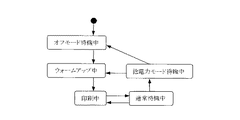
表1に示す静的な情報のうち、ステータス移行時間は、省エネ(省エネルギー)に関する低電力モード移行時間とオフモード移行時間に相当する。なお、後述するウォームアップタイムを含めても良い。消費電力値は、各ステータスの移行(各電力モード)時に必要な単位時間当りの電力に相当する。表2に示す動的な情報としてのステータス情報はエンジン(印刷部)の現時点の電力モード(状態)について示しており、例えばオフモード,低電力モード,通常待機モード,印刷モードの4つの電力モードがある。 Among the static information shown in Table 1, the status transition time corresponds to the low power mode transition time and the off mode transition time related to energy saving (energy saving). Note that a warm-up time described later may be included. The power consumption value corresponds to the power per unit time required at each status transition (each power mode). The status information as dynamic information shown in Table 2 indicates the current power mode (state) of the engine (printing unit). For example, four power modes of off mode, low power mode, normal standby mode, and print mode are shown. There is.
各MFP10では、例えば表3に示すようなプロパティを図3の記憶部124(ROM304,NVRAM305,HDD306)に記憶保持している。そして、そのプロパティのうち、動的な情報であるステータス情報を、自機の電力モードが移行する(切り替わる)度にその移行後の電力モードを示す情報に更新する。
ここで、表3に示すプロパティのうち、ステータス移行(電力モード移行)時間は、例えば表4に示す通りである。表4では、オフモードから低電力モードへの時間が10秒、オフモードから通常待機モードへの移行時間は20秒、低電力モードから通常待機モードへの移行時間が15秒となっている。
In each
Here, among the properties shown in Table 3, the status transition (power mode transition) time is as shown in Table 4, for example. In Table 4, the time from the off mode to the low power mode is 10 seconds, the transition time from the off mode to the normal standby mode is 20 seconds, and the transition time from the low power mode to the normal standby mode is 15 seconds.
各MFP10では、図3に示した通信処理部121,時間計測部122,電力制御部123,記憶部124,エンジン(印刷部)14,操作部107の消費電力は、各電力モード毎に異なる。例えば、オフモード時には、通信処理部121のみが通常消費電力(低消費電力と高消費電力の間)、それ以外は全て低消費電力となっている。低電力モード時には、エンジン14と操作部107が低消費電力、それら以外は全て通常消費電力となっている。通常待機モード時には、全てが通常消費電力となっている。印刷モード時には、エンジン14のみが高消費電力、それ以外は全て通常消費電力となっている。そのため、1秒当りの消費電力〔W〕は、例えば表5に示すように、オフモード時には1〔W〕、低電力モード時には2〔W〕、通常待機モード時には10〔W〕、印刷モード時には15〔W〕となる。
In each

次に、MFP10で印刷指示を受けてから印刷文書データによる印刷が終了するまでに消費される消費電力量(印刷に必要な電力量)E〔Wh〕の計算方法について、図7〜図10を参照して具体的に説明する。
図7は、各MFP10における各電力モード時の消費電力Pと時間tとの関係の一例を示す線図である。
Next, FIG. 7 to FIG. 10 show a calculation method of power consumption (power consumption necessary for printing) E [Wh] consumed from when the
FIG. 7 is a diagram showing an example of the relationship between power consumption P and time t in each power mode in each
ここでは、各MFP10のプロパティの一部である4つの電力モード時の消費電力P〔W〕、つまりオフモード時の消費電力POFF,低電力モード時の消費電力PLOW ,通常待機モード時の消費電力PWAIT,印刷モード時(印刷時)の消費電力PRUN の他に、ウォームアップモード時(ウォームアップ時)の消費電力PWARM を加えている。そのウォームアップモードの期間をウォームアップタイムTWARM、印刷モードの期間を印刷時間TRUN、通常待機モードの期間を低電力モード移行時間TLOW 、低電力モードの期間をオフモード移行時間TOFF という。
Here, the power consumption P [W] in four power modes, which are part of the properties of each
MFP10での印刷文書データの印刷によって消費される消費電力量E〔Wh〕は、MFP10が印刷管理サーバ30から印刷指示を受けてウォームアップモードに移行してから印刷が終了してオフモードに移行するまでに消費される電力量なので、次式によって求めることができる。
E=PWARM・TWARM+PRUN・TRUN+PWAIT・TLOW+PLOW・TOFF
ここで、PWARM,PRUN,PWAIT,PLOWは機器(MFP10)固有の値である。
ウォームアップタイムTWARMは、機器固有の値であり、機器の状態に依存する。つまり、MFP10の各電力モードが図8に示すような関係になっているため、表6に示すように、印刷依頼を受けた時点での電力モードによって変化する。
The power consumption E [Wh] consumed by printing of the print document data in the
E = PWARM · TWARM + PRUN · TRUN + PWAIT · TLOW + PLOW · TOFF
Here, PWARM, PRUN, PWAIT, and PLOW are values unique to the device (MFP 10).
The warm-up time TWARM is a value unique to the device and depends on the state of the device. That is, since each power mode of the
印刷時間TRUN は、機器固有の値であり、印刷条件の一つである印刷枚数に依存する。
図9は、印刷時間TRUN と印刷枚数との関係の一例を示す線図である。
この図9を見て分かるように、1枚目の印刷(ファーストプリント)に最も時間がかかる。
よって、印刷時間は、電力モードとファーストプリント(1枚目)と連続プリント(2枚目以降)との組み合わせによって決定できる。
例えば、表7に示すように、片面印刷モード時のファーストプリントをTRUNs1st、連続プリントをTRUNs とし、両面印刷モード時のファーストプリントをTRUNb1st 、連続プリントをTRUNbとすると、印刷時間は次のようになる。
The printing time TRUN is a value unique to the device and depends on the number of printed sheets, which is one of the printing conditions.
FIG. 9 is a diagram showing an example of the relationship between the printing time TRUN and the number of printed sheets.
As can be seen from FIG. 9, the first printing (first print) takes the longest time.
Therefore, the printing time can be determined by a combination of the power mode, the first print (first sheet), and the continuous print (second sheet or later).
For example, as shown in Table 7, when the first print in the single-sided printing mode is TRUNs1st, the continuous printing is TRUNs, the first printing in the double-sided printing mode is TRUNb1st, and the continuous printing is TRUNb, the printing time is as follows. .
すなわち、片面印刷モードで1枚のみ印刷する場合の印刷時間TRUN は、次式によって求めることができる。
TRUN=TRUNs1st
片面印刷モードで2枚以上印刷する場合の印刷時間TRUN は、次式によって求めることができる。
TRUN=TRUNs1st+TRUNs×n枚
両面印刷モードで1枚のみ印刷する場合の印刷時間TRUN は、次式によって求めることができる。
TRUN=TRUNb1st
両面印刷モードで2枚以上印刷する場合の印刷時間TRUN は、次式によって求めることができる。
TRUN=TRUNb1st+TRUNb×n枚
That is, the printing time TRUN when only one sheet is printed in the single-sided printing mode can be obtained by the following equation.
TRUN = TRUNs1st
The printing time TRUN when printing two or more sheets in the single-sided printing mode can be obtained by the following equation.
TRUN = TRUNs1st + TRUNs × n sheets The printing time TRUN when only one sheet is printed in the duplex printing mode can be obtained by the following equation.
TRUN = TRUNb1st
The printing time TRUN when printing two or more sheets in the duplex printing mode can be obtained by the following equation.
TRUN = TRUNb1st + TRUNb × n
低電力モード移行時間TLOWおよびオフモード移行時間TOFFは、機器固有の値であり、設定値に依存する。
したがって、印刷時の消費電力量が大きい機器でも、機器の状態,印刷枚数,モード移行時間(電力モードの移行時間)の設定値によっては、印刷時の消費電力量が小さい機器よりトータルな消費電力量が少ない場合がある。
図10の(a)は印刷時の消費電力量が小さいオフモードのMFP(機器)における各電力モード時の消費電力Pと時間tとの関係の一例を、同図の(b)は印刷時の消費電力量が大きい通常待機のMFPにおける各電力モード時の消費電力Pと時間tとの関係の一例をそれぞれ示す線図である。
この図10を見て分かるように、後者のMFPの方が消費電力量が少なくなる。
The low power mode transition time TLOW and the off mode transition time TOFF are values unique to the device and depend on the set values.
Therefore, even for devices that consume a large amount of power during printing, depending on the device status, number of printed sheets, and mode transition time (power mode transition time), the total power consumption will be greater than that of devices that consume less power during printing. The amount may be small.
FIG. 10A shows an example of the relationship between the power consumption P and the time t in each power mode in an off-mode MFP (apparatus) with a small amount of power consumption at the time of printing, and FIG. 6 is a diagram showing an example of the relationship between power consumption P and time t in each power mode in a normal standby MFP with a large amount of power consumption.
As can be seen from FIG. 10, the latter MFP consumes less power.
次に、PC20から印刷管理サーバ30へ送信される印刷依頼について、図11を参照して具体的に説明する。
印刷依頼(印刷命令)には、以下の(A)(B)に示す2種類のパターンがある。
Next, a print request transmitted from the
The print request (print command) includes the following two types of patterns (A) and (B).
(A)計算プログラムが印刷管理サーバ30又はMFP10にあるパターン
このパターンの場合、つまりMFP10で印刷指示を受けてから印刷文書データの印刷が終了するまでに消費される消費電力量を計算するための計算プログラムが印刷管理サーバ30又はMFP10にあるパターンの場合、印刷依頼は引数として文書データ,印刷条件,機器選択条件を持つ。
(B)計算プログラムがPC20にあるパターン
このパターンの場合、印刷依頼は引数として文書データ,印刷条件,機器選択条件,計算プログラムを持つ。
(A) Pattern in which the calculation program is in the
(B) Pattern in which the calculation program is in the
引数としての印刷条件,機器選択条件,および計算プログラムの詳細は、以下に示す通りである。
(1)印刷条件
この印刷条件は、文書をどのような形で印刷するかという条件であり、表8に示すような各種の属性からなる。
Details of printing conditions, device selection conditions, and calculation programs as arguments are as follows.
(1) Print condition This print condition is a condition as to how a document is to be printed, and includes various attributes as shown in Table 8.
・原稿サイズ
印刷する文書の大きさ(例:A4,B5)を示すものである。
・用紙サイズ
印刷する用紙の大きさ(例:A4,B5)を示すものである。
・部数
印刷する部数である。
Document size This indicates the size of the document to be printed (example: A4, B5).
-Paper size This indicates the size of the paper to be printed (example: A4, B5).
-Number of copies This is the number of copies to be printed.
・原稿方向
印刷する文書が縦長の原稿か横長の原稿かを示すものである。
・白黒/カラー
印刷を白黒で行うか、カラーで行うかを示すものである。
・集約設定
用紙1ページに複数ページの原稿を印刷するかどうかの設定内容、あるいは何ページの原稿を集約するか(例:原稿2ページ→用紙1ページ)どうかの設定内容を示すものである。
-Original orientation Indicates whether the document to be printed is a portrait or landscape document.
・ Monochrome / Color Indicates whether printing is performed in black and white or in color.
Aggregation setting This indicates a setting content for determining whether or not to print a plurality of pages of a document on one sheet of paper, or a setting content for determining how many pages of a document are to be consolidated (for example, 2 pages of a document to 1 page of a sheet).
・両面設定
用紙の両面に印刷するかどうかの設定内容を示すものである。
・ステープル設定
印刷された用紙に対し、部数毎にステープルを打つかどうかの設定内容を示すものである。
・パンチ設定
印刷された用紙に対し、パンチ穴をあけるかどうかの設定内容を示すものである。
-Duplex setting This indicates the setting contents for whether or not to print on both sides of the paper.
Staple setting This indicates the setting contents for whether or not staples are printed for each number of copies on the printed paper.
-Punch setting This indicates the setting contents for whether or not to punch holes on printed paper.
(2)機器選択条件
この機器選択条件は、MFP10を選択するための条件あり、表9に示すような各種の属性からなる。
(2) Device Selection Condition The device selection condition is a condition for selecting the
・自動/指定
MFP10の選択を印刷管理サーバ30に自動で行わせるか/ユーザが自分で指定するかを示すものである。
・出力場所
MFP10の選択を印刷管理サーバ30に自動で行わせる場合、どこに設置されているMFP10に印刷させるかという条件を示すものである。
Automatic / Designation Indicates whether the
Output Location When the
・優先設定
消費電力量がもっとも少ないMFP10を選択するか/スピードが最も速いMFP10を選択するかを示すものである。
・機器名
印刷に使用するMFP10をユーザが指定する場合、どのMFP10に印刷させるか、そのMFP(機器)10の名称を示すものである。
Priority setting This indicates whether to select the
Device Name When the user designates the
図11は、PC20の表示装置230に表示される印刷条件および機器選択条件を入力するための操作画面の一例を示す図である。
この操作画面上をユーザが入力装置220(例えばマウス)によって操作することにより、任意の印刷条件および機器選択条件を入力することができる。
FIG. 11 is a diagram illustrating an example of an operation screen for inputting printing conditions and device selection conditions displayed on the
Arbitrary printing conditions and device selection conditions can be input by the user operating the operation screen with the input device 220 (for example, a mouse).
(3)計算プログラム(ここではPC20にあるパターンの場合のみ)
この計算プログラムは、印刷条件およびMFP10のプロパティからMFP10の消費電力量を計算するためのプログラムである。
(3) Calculation program (in this case, only for patterns in PC20)
This calculation program is a program for calculating the power consumption of the
このように構成された印刷依頼で印刷管理サーバ30が実行できる処理は、以下の(a)〜(c)に示す通りである。
(a)印刷管理サーバ30は、自己に接続されている全てのMFP10の中から機器選択条件に合うものを探す。
(b)印刷管理サーバ30は、機器選択条件に合うMFP10の中から最も消費電力量の少ないものを判断する。
(c)最も消費電力量の少ない画像形成装置に対して印刷指示を送信する。
The processes that can be executed by the
(A) The
(B) The
(C) A print instruction is transmitted to the image forming apparatus that consumes the least amount of power.
次に、印刷管理サーバ30からMFP10へ送信される印刷指示について、図12を参照して具体的に説明する。
この印刷指示は、引数として文書データおよび印刷条件を持つ。
MFP10は、文書データおよび印刷条件を含む印刷指示を受けると、その文書データをその印刷条件に従って印刷を行った後、印刷終了通知を印刷管理サーバ30へ返す。
Next, a print instruction transmitted from the
This print instruction has document data and print conditions as arguments.
When the
次に、MFP10から印刷管理サーバ30経由でPC20へ送信される印刷終了通知について説明する。
この印刷終了通知は、引数として表10に示すような印刷結果および機器名(印刷を行ったMFP10の名称)を持つ。
ここで、印刷結果は、印刷が成功したか/失敗したかを示すものであり、印刷が失敗した場合はその理由(紙づまり,故障など)を付加する。
Next, a print end notification transmitted from the
This print end notification has a print result and a device name (name of the
Here, the printing result indicates whether the printing has succeeded or failed. If printing has failed, the reason (paper jam, failure, etc.) is added.
印刷管理サーバ30は、いずれかのMFP10から印刷終了通知を受けると、それをPC20へ返す。
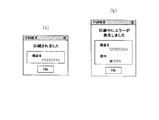
PC20の装置本体200内のCPU201は、印刷管理サーバ30から印刷終了通知を受けると、その印刷終了通知中の印刷結果を機器名と共に表示装置230に表示する。その印刷結果の異なる表示例を図12に示す。図12の(a)は印刷が成功した旨を知らせる表示例を、同図の(b)は印刷が失敗した旨をその理由と共に知らせる表示例をそれぞれ示す。
When the
When the
次に、上述したように構成した画像形成システムにおけるこの発明に係わる具体的な制御の異なる例(各実施例)について、図13〜図20を参照して具体的に説明する。なお、説明の都合上、2台のMFP10a,10bしか存在しないものとする。
Next, specific examples (each embodiment) of specific control according to the present invention in the image forming system configured as described above will be specifically described with reference to FIGS. For convenience of explanation, it is assumed that there are only two
〔第1実施例〕
まず、PC20と印刷管理サーバ30と各MFP10との間の通信シーケンスの第1例について、図13を参照して説明する。
この第1実施例の場合、各MFP10別の計算プログラムは、印刷管理サーバ30のHDD306に記憶保持され、印刷管理サーバ30の起動時にSDRAM303に展開されているものとする。
[First embodiment]
First, a first example of a communication sequence among the
In the case of the first embodiment, it is assumed that the calculation program for each
また、印刷管理サーバ30のCPU301が、ROM304上のプログラムやSDRAM303上のプログラムに従って動作し、必要に応じてUSB・I/F308,IEEE1394・I/F309,又はMAC・I/F310を選択的に使用することにより、機器選択手段,プロパティ取得手段,計算プログラム記憶手段としての機能を果たす。
さらに、各MFP10のCPU101が、ROM104上のプログラムに従って動作し、必要に応じて図2のSDRAM103,NVRAM105,HDD106,USB・I/F109,IEEE1394・I/F110,MAC・I/F111を選択的に使用することにより、プロパティ通知手段としての機能を果たす。
The
Further, the
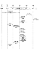
図13は、PC20と印刷管理サーバ30と各MFP10との間の通信シーケンスの第1例を示す図である。
PC20のCPU201は、ユーザによる入力装置220の操作により、文書データが生成され、且つ印刷条件および機器選択条件が入力された後、印刷要求がなされると(S101)、その生成された文書データと入力された印刷条件および機器選択条件とを含む印刷依頼を印刷管理サーバ30へ送信する(S102)。
印刷管理サーバ30のCPU301は、PC20から印刷依頼を受信すると、一方のMFP10aに対してそのプロパティを要求する(S103)。
FIG. 13 is a diagram illustrating a first example of a communication sequence among the
When the
When receiving the print request from the
MFP10aのCPU101は、印刷管理サーバ30からプロパティの要求を受けると、MFP10aのプロパティを印刷管理サーバ30へ通知する(S104)。
印刷管理サーバ30のCPU301は、MFP10aへのプロパティの要求に対して、MFP10aからそのプロパティを取得すると、SDRAM303上のMFP10a用の計算プログラムに従い、受信した印刷依頼中の印刷条件および取得したMFP10aのプロパティに基づいてMFP10aの消費電力量(MFP10aで印刷指示を受けてから文書データの印刷が終了するまでに消費される消費電力量)を計算した後(S105)、今度は他方のMFP10bに対してそのプロパティを要求する(S106)。
Upon receiving a property request from the
When the
MFP10bのCPU101は、印刷管理サーバ30からプロパティの要求を受けると、MFP10bのプロパティを印刷管理サーバ30へ通知する(S107)。
印刷管理サーバ30のCPU301は、MFP10bへのプロパティの要求に対して、MFP10bからそのプロパティを取得すると、SDRAM303上のMFP10b用の計算プログラムに従い、受信した印刷依頼中の印刷条件および取得したMFP10bのプロパティに基づいてMFP10bの消費電力量を計算する(S108)。
Upon receiving a property request from the
When the
各MFP10別の消費電力量の計算が完了すると、それらの計算結果を比較し、その比較結果から最適なMFP10を判断し、それを印刷使用機器として選択する(S109)。つまり、受信した印刷依頼中の機器選択条件が印刷スピードよりも省エネを優先するものであった場合には、上記各計算結果から最も消費電力量の少ないMFP10を最適機器と判断し、印刷使用機器として選択する。印刷依頼中の機器選択条件が省エネよりも印刷スピードを優先するものであった場合には、最も印刷スピードのあるMFP10を最適機器と判断し、印刷使用機器として選択するが、これについての詳細は省略する。なお、受信した印刷依頼に機器選択条件が含まれていない場合に、上記各計算結果から最も消費電力量の少ないMFP10を最適機器と判断し、印刷使用機器として選択するようにしてもよい。
When the calculation of the power consumption for each
印刷管理サーバ30のCPU301は、印刷使用機器の選択処理が完了すると、先に受信した印刷依頼中の文書データおよび印刷条件を含む印刷指示を印刷使用機器として選択したMFP10(この例ではMFP10aとする)へ送信する(S110)。
MFP10aのCPU101は、印刷管理サーバ30から印刷指示を受信すると、その印刷指示中の印刷条件に基づいてその印刷指示中の文章データを可視画像として用紙上に印刷する印刷処理を行った後、その印刷結果と自機の名称(機器名)を含む印刷終了通知を印刷管理サーバ30へ送信する(S111)。
When the selection processing of the print use device is completed, the
When the
印刷管理サーバ30のCPU301は、MFP10aから印刷終了通知を受けると、それをPC20へ送信する(S112)。
PC20のCPU201は、印刷管理サーバ30から印刷終了通知を受けると、その印刷終了通知中の印刷結果を機器名と共に表示装置230の画面に表示して、ユーザに知らせる(S113)。
Upon receiving the print end notification from the
When receiving the print end notification from the
このように、第1実施例によれば、印刷管理サーバ30が、PC20から文書データ(印刷データ)および所要条件(印刷条件,機器選択条件)を含む印刷依頼を受けた場合に、各MFP10からそれらのプロパティを取得し、その所要条件および各MFP10のプロパティに基づいて各MFP10のいずれかを印刷使用機器として選択する。つまり、予め記憶保持した各MFP10別の計算プログラムに従い、上記印刷条件および各MFP10のプロパティに基づいて各MFP10別の消費電力量をそれぞれ計算し、その各計算結果および上記機器選択条件に基づいて各MFP10のいずれかを印刷使用機器として選択する。よって、複数台のMFP10の中から所要条件を確実に満たすMFP10(最も消費電力量が少ないMFP10又は最も印刷スピードのあるMFP10)を印刷使用機器として使用することができる。
As described above, according to the first embodiment, when the
〔第2実施例〕
次に、PC20と印刷管理サーバ30と各MFP10との間の通信シーケンスの第2例について、図14を参照して説明する。
この第2実施例の場合、各MFP10別の計算プログラムは、PC20のHDD206に記憶保持されているものとする。
[Second Embodiment]
Next, a second example of a communication sequence among the
In the case of the second embodiment, it is assumed that the calculation program for each
また、印刷管理サーバ30のCPU301が、ROM304上のプログラムやSDRAM303上のプログラムに従って動作し、必要に応じてUSB・I/F308,IEEE1394・I/F309,又はMAC・I/F310を選択的に使用することにより、機器選択手段,プロパティ取得手段,計算プログラム取得手段,計算プログラム記憶手段としての機能を果たす。
さらに、各MFP10のCPU101が、ROM104上のプログラムに従って動作し、必要に応じて図2のSDRAM103,NVRAM105,HDD106,USB・I/F109,IEEE1394・I/F110,MAC・I/F111を選択的に使用することにより、プロパティ通知手段としての機能を果たす。
The
Further, the
図14は、PC20と印刷管理サーバ30と各MFP10との間の通信シーケンスの第2例を示す図である。
FIG. 14 is a diagram illustrating a second example of a communication sequence among the
PC20のCPU201は、ユーザによる入力装置220の操作により、文書データが生成され、且つ印刷条件および機器選択条件が入力された後、印刷要求がなされると(S201)、HDD206内の各MFP10別の計算プログラムを読み出し、上記生成された文書データと入力された印刷条件および機器選択条件とHDD206から読み出した各MFP10別の計算プログラムとを含む印刷依頼を印刷管理サーバ30へ送信する(S202)。
When the
印刷管理サーバ30のCPU301は、PC20から印刷依頼を受信すると、その印刷依頼中の各MFP10別の計算プログラムをSDRAM303上に展開した後、一方のMFP10aに対してそのプロパティを要求する(S203)。
以後の印刷管理サーバ30,各MFP10,およびPC20によるステップS204〜S213の制御(処理)は、図13によって説明したステップS104〜S113の制御と同様なので、それらの説明を省略する。
When receiving a print request from the
The subsequent control (processing) of steps S204 to S213 by the
このように、第2実施例によれば、印刷管理サーバ30が、PC20から文書データ,所要条件(印刷条件,機器選択条件),および各MFP10別の計算プログラムを含む印刷依頼を受けた場合に、各MFP10からそれらのプロパティを取得し、その各MFP10別の計算プログラムに従い、その印刷条件および各MFP10のプロパティに基づいて各MFP10別の消費電力量をそれぞれ計算し、その各計算結果および機器選択条件に基づいて各MFP10のいずれかを印刷使用機器として選択するので、第1実施例と同様の効果を得ることができる。
As described above, according to the second embodiment, when the
また、PC20側で各MFP10別の計算プログラムを記憶保持するため、印刷管理サーバ30側ではその計算プログラムをメモリ(SDRAM203)に常駐させる必要がなくなる。よって、印刷管理サーバ30では、ネットワーク1上に複数台のPC20が接続されているような場合でも、PC20から印刷時にのみ送られてくる各MFP10別の計算プログラムをメモリに一時的にすれば良いため、メモリを効率良く使用できる。
Further, since the calculation program for each
〔第3実施例〕
次に、PC20と印刷管理サーバ30と各MFP10との間の通信シーケンスの第3例について、図15を参照して説明する。
この第3実施例の場合、各MFP10別の計算プログラムは、各MFP10のHDD106に記憶保持されているものとする。
[Third embodiment]
Next, a third example of a communication sequence among the
In the case of the third embodiment, it is assumed that the calculation program for each
また、印刷管理サーバ30のCPU301が、ROM304上のプログラムやSDRAM303上のプログラムに従って動作し、必要に応じてUSB・I/F308,IEEE1394・I/F309,又はMAC・I/F310を選択的に使用することにより、機器選択手段,プロパティ取得手段,計算プログラム取得手段,計算プログラム記憶手段としての機能を果たす。
さらに、各MFP10のCPU101が、ROM104上のプログラムに従って動作し、必要に応じて図2のSDRAM103,NVRAM105,HDD106,USB・I/F109,IEEE1394・I/F110,MAC・I/F111を選択的に使用することにより、プロパティ通知手段および計算プログラム通知手段としての機能を果たす。
The
Further, the
図15は、PC20と印刷管理サーバ30と各MFP10との間の通信シーケンスの第3例を示す図である。
PC20のCPU201は、ユーザによる入力装置220の操作により、文書データが生成され、且つ印刷条件および機器選択条件が入力された後、印刷要求がなされると(S301)、その生成された文書データと入力された印刷条件および機器選択条件とを含む印刷依頼を印刷管理サーバ30へ送信する(S302)。
FIG. 15 is a diagram illustrating a third example of a communication sequence among the
The
印刷管理サーバ30のCPU301は、PC20から印刷依頼を受信すると、一方のMFP10aに対してそのプロパティを要求する(S303)。
MFP10aのCPU101は、印刷管理サーバ30からプロパティの要求を受けると、MFP10aのプロパティを印刷管理サーバ30へ通知する(S304)。
印刷管理サーバ30のCPU301は、MFP10aへのプロパティの要求に対して、MFP10aからそのプロパティを取得すると、MFP10aに対して計算プログラムを要求する(S305)。
When receiving the print request from the
Upon receiving a property request from the
When the
MFP10aのCPU101は、印刷管理サーバ30から計算プログラムの要求を受けると、MFP10a用の計算プログラムを印刷管理サーバ30へ通知(送信)する(S306)。
印刷管理サーバ30のCPU301は、MFP10aへの計算プログラムの要求に対して、MFP10aから計算プログラムを取得すると、それをSDRAM303上に展開し、その計算プログラムに従い、受信した印刷依頼中の印刷条件および取得したMFP10aのプロパティに基づいてMFP10aの消費電力量を計算した後(S307)、今度は他方のMFP10bに対してそのプロパティを要求する(S308)。
Upon receiving a calculation program request from the
When the
MFP10bのCPU101は、印刷管理サーバ30からプロパティの要求を受けると、MFP10bのプロパティを印刷管理サーバ30へ通知する(S309)。
印刷管理サーバ30のCPU301は、MFP10bへのプロパティの要求に対して、MFP10bからそのプロパティを取得すると、MFP10bに対して計算プログラムを要求する(S310)。
MFP10bのCPU101は、印刷管理サーバ30から計算プログラムの要求を受けると、MFP10b用の計算プログラムを印刷管理サーバ30へ通知する(S311)。
Upon receiving a property request from the
When the
Upon receiving a calculation program request from the
印刷管理サーバ30のCPU301は、MFP10bへの計算プログラムの要求に対して、MFP10bから計算プログラムを取得すると、それをSDRAM303上に展開し、その計算プログラムに従い、受信した印刷依頼中の印刷条件および取得したMFP10bのプロパティに基づいてMFP10bの消費電力量を計算する(S312)。
以後の印刷管理サーバ30およびPC20によるステップS313〜S317の制御は、図13によって説明したステップS109〜S113の制御と同様なので、それらの説明を省略する。
When the
The subsequent control of steps S313 to S317 by the
このように、第3実施例によれば、印刷管理サーバ30が、PC20から文書データ,所要条件(印刷条件,機器選択条件)を含む印刷依頼を受けた場合に、各MFP10からそれらのプロパティと各MFP10別の計算プログラムとを取得し、その各MFP10別の計算プログラムに従い、その印刷条件および各MFP10のプロパティに基づいて各MFP10別の消費電力量をそれぞれ計算し、その各計算結果および機器選択条件に基づいて各MFP10のいずれかを印刷使用機器として選択するので、第1実施例と同様の効果を得ることができる。
As described above, according to the third embodiment, when the
また、各MFP10からその各MFP10別の計算プログラムを取得するため、印刷管理サーバ30側ではその計算プログラムをメモリに常駐させる必要がなくなる。よって、印刷管理サーバ30では、ネットワーク1上に複数台のPC20が接続されているような場合でも、印刷時にのみ各MFP10から計算プログラムを取得してメモリに一時的に記憶すれば良いため、メモリを効率良く使用できる。
Further, since the calculation program for each
〔第4実施例〕
次に、PC20と印刷管理サーバ30と各MFP10との間の通信シーケンスの第4例について、図16を参照して説明する。
この第4実施例の場合、各MFP10別の計算プログラムは、印刷管理サーバ30のHDD306に記憶保持され、印刷管理サーバ30の起動時にSDRAM303に展開されているものとする。
[Fourth embodiment]
Next, a fourth example of a communication sequence among the
In the case of the fourth embodiment, it is assumed that the calculation program for each
また、印刷管理サーバ30のCPU301が、ROM304上のプログラムやSDRAM303上のプログラムに従って動作し、必要に応じてUSB・I/F308,IEEE1394・I/F309,又はMAC・I/F310を選択的に使用することにより、機器選択手段,プロパティ登録手段,計算プログラム記憶手段としての機能を果たす。
さらに、各MFP10のCPU101が、ROM104上のプログラムに従って動作し、必要に応じて図2のSDRAM103,NVRAM105,HDD106,USB・I/F109,IEEE1394・I/F110,MAC・I/F111を選択的に使用することにより、プロパティ通知手段としての機能を果たす。
The
Further, the
図16は、PC20と印刷管理サーバ30と各MFP10との間の通信シーケンスの第4例を示す図である。
MFP10aのCPU101は、MFP10aが管理者によって設置され(例えばネットワーク1に接続され)た後(S401)、電源オンによって起動すると、MFP10aのプロパティを印刷管理サーバ30へ通知する(S402)。その後、MFP10aの電力モードが移行する(例えば通常待機モードから低電力モードに移行する)と(S405)、その旨を移行後の電力モードと共に印刷管理サーバ30へ通知する(S406)。この通知は、電力モードが移行する毎に行う。
FIG. 16 is a diagram illustrating a fourth example of a communication sequence among the
After the
MFP10bのCPU101も、MFP10bが管理者によって設置された後(S403)、電源オンによって起動すると、MFP10bのプロパティを印刷管理サーバ30へ通知する(S404)。その後、MFP10bの電力モードが移行すると(S407)、その旨を移行後の電力モードと共に印刷管理サーバ30へ通知する(S408)。この通知も、電力モードが移行する毎に行う。
After the
印刷管理サーバ30のCPU301は、MFP10a,10bからそれぞれプロパティが通知されてくると、それらのプロパティを登録し(HDD306又はNVRAM305に記憶保持し)、その後MFP10a又は10bから電力モードが移行した旨の通知を受ける度に、登録しているプロパティのうちのステータス情報を移行後の電力モードを示す情報に更新する。
When the properties are notified from the
一方、PC20のCPU201は、ユーザによる入力装置220の操作により、文書データが生成され、且つ印刷条件および機器選択条件が入力された後、印刷要求がなされると(S409)、その生成された文書データと入力された印刷条件および機器選択条件とを含む印刷依頼を印刷管理サーバ30へ送信する(S410)。
印刷管理サーバ30のCPU301は、PC20から印刷依頼を受信すると、SDRAM303上のMFP10a用の計算プログラムに従い、受信した印刷依頼中の印刷条件および予め登録してあるMFP10aのプロパティに基づいてMFP10aの消費電力量を計算する(S411)。
On the other hand, the
When the
次いで、SDRAM303上のMFP10b用の計算プログラムに従い、受信した印刷依頼中の印刷条件および予め登録してあるMFP10bのプロパティに基づいてMFP10bの消費電力量を計算する(S412)。
以後の印刷管理サーバ30およびPC20によるステップS413〜S417の制御は、図13によって説明したステップS109〜S113の制御と同様なので、それらの説明を省略する。
Next, according to the calculation program for the
The subsequent control of steps S413 to S417 by the
このように、第4実施例によれば、印刷管理サーバ30が、各MFP10からそれぞれ通知されたプロパティを登録した後、PC20から文書データ,所要条件(印刷条件,機器選択条件)を含む印刷依頼を受けた場合に、予め記憶保持した各MFP10別の計算プログラムに従い、その印刷条件および各MFP10のプロパティに基づいて各MFP10別の消費電力量をそれぞれ計算し、その各計算結果および機器選択条件に基づいて各MFP10のいずれかを印刷使用機器として選択するので、第1実施例と同様の効果を得ることができる。
As described above, according to the fourth embodiment, after the
また、各MFP10の起動時(他のタイミングでもよい)に通知されるプロパティを登録するため、印刷管理サーバ30側ではPC20から印刷依頼を受信するたびに各MFP10からそれらのプロパティを取得する必要がなくなる。よって、印刷管理サーバ30では、その分だけ各MFP10のいずれかを印刷使用機器として選択するまでの処理時間が短縮されるため、結果的に印刷時間の高速化につながる。
In addition, in order to register properties to be notified when each
なお、第4実施例では、第1実施例と同様に、印刷管理サーバ30が、各MFP10別の計算プログラムを記憶保持するようにしたが、第2実施例と同様に、PC20側に各MFP10別の計算プログラムを記憶保持し、それを印刷管理サーバ30がPC20からの印刷依頼時に受け取ったり、あるいは、第3実施例と同様に、印刷管理サーバ30が各MFP10からその各MFP10別の計算プログラムを取得することもできる。
In the fourth embodiment, as in the first embodiment, the
〔第5実施例〕
次に、PC20と印刷管理サーバ30と各MFP10との間の通信シーケンスの第5例について、図17を参照して説明する。
この第5実施例の場合、各MFP10別の計算プログラムは、印刷管理サーバ30のHDD306に記憶保持され、印刷管理サーバ30の起動時にSDRAM303に展開されているものとする。
[Fifth embodiment]
Next, a fifth example of a communication sequence among the
In the case of the fifth embodiment, it is assumed that the calculation program for each
また、印刷管理サーバ30のCPU301が、ROM304上のプログラムやSDRAM303上のプログラムに従って動作し、必要に応じてUSB・I/F308,IEEE1394・I/F309,又はMAC・I/F310を選択的に使用することにより、機器選択手段,プロパティ登録手段,計算プログラム記憶手段としての機能を果たす。
さらに、各MFP10のCPU101が、ROM104上のプログラムに従って動作し、必要に応じて図2のSDRAM103,NVRAM105,HDD106,USB・I/F109,IEEE1394・I/F110,MAC・I/F111を選択的に使用することにより、プロパティ通知手段としての機能を果たす。
The
Further, the
図17は、PC20と印刷管理サーバ30と各MFP10との間の通信シーケンスの第5例を示す図である。
印刷管理サーバ30のCPU301は、管理者によって各MFP10のプロパティが入力され、その登録の指示がなされると(S501)、その各MFP(機器)10のプロパティを登録する(HDD306又はNVRAM305に記憶保持する)。例えば、図示しない管理者用のPCのCPUが、管理者による入力装置の操作により、各MFP10のプロパティが入力された後、その登録要求がなされることにより、その入力された各MFP10のプロパティを印刷管理サーバ30へ送信すると、印刷管理サーバ30のCPU301は、その各MFP10のプロパティを受信して登録する。
FIG. 17 is a diagram illustrating a fifth example of a communication sequence among the
The
MFP10aのCPU101は、MFP10aの電力モードが移行する(切り替わる)と(S502)、その旨を移行後の電力モードと共に印刷管理サーバ30へ通知する(S503)。この通知は、電力モードが移行する毎に行う。
MFP10bのCPU101も、MFP10aの電力モードが移行すると(S504)、その旨を移行後の電力モードと共に印刷管理サーバ30へ通知する(S505)。この通知も、電力モードが移行する毎に行う。
印刷管理サーバ30のCPU301は、各MFP10のプロパティを登録した後、MFP10a又は10bから電力モードが移行した旨の通知を受ける度に、登録しているプロパティのうちのステータス情報を移行後の電力モードを示す情報に更新する。
When the power mode of the
When the power mode of the
After registering the properties of each
一方、PC20のCPU201は、ユーザによる入力装置220の操作により、文書データが生成され、且つ印刷条件および機器選択条件が入力された後、印刷要求がなされると(S506)、その生成された文書データと入力された印刷条件および機器選択条件とを含む印刷依頼を印刷管理サーバ30へ送信する(S507)。
以後の印刷管理サーバ30およびPC20によるステップS508〜S514の制御は、図16によって説明したステップS411〜S417の制御と同様なので、それらの説明を省略する。
On the other hand, when the
The subsequent control of steps S508 to S514 by the
このように、第5実施例によれば、印刷管理サーバ30が、管理者の操作によって入力された各MFP10のプロパティを登録した後、PC20から文書データ,所要条件(印刷条件,機器選択条件)を含む印刷依頼を受けた場合に、予め記憶保持した各MFP10別の計算プログラムに従い、その印刷条件および各MFP10のプロパティに基づいて各MFP10別の消費電力量をそれぞれ計算し、その各計算結果および機器選択条件に基づいて各MFP10のいずれかを印刷使用機器として選択するので、第1実施例と同様の効果を得ることができる。
As described above, according to the fifth embodiment, after the
また、管理者の操作によって入力されるプロパティを登録するため、印刷管理サーバ30側ではPC20から印刷依頼を受信するたびに各MFP10からそれらのプロパティを取得する必要がなくなる。よって、印刷管理サーバ30では、その分だけ各MFP10のいずれかを印刷使用機器として選択するまでの処理時間が短縮されるため、結果的に印刷時間の高速化につながる。
Also, since the properties input by the operation of the administrator are registered, it is not necessary for the
なお、第5実施例でも、第1実施例と同様に、印刷管理サーバ30が、各MFP10別の計算プログラムを記憶保持するようにしたが、第2実施例と同様に、PC20側に各MFP10別の計算プログラムを記憶保持し、それを印刷管理サーバ30がPC20からの印刷依頼時に受け取ったり、あるいは、第3実施例と同様に、印刷管理サーバ30が各MFP10からその各MFP10別の計算プログラムを取得することもできる。
In the fifth embodiment, as in the first embodiment, the
〔第6実施例〕
次に、PC20と印刷管理サーバ30と各MFP10との間の通信シーケンスの第6例について、図18を参照して説明する。
この第6実施例の場合、各MFP10別の計算プログラムは、印刷管理サーバ30のHDD306に記憶保持され、印刷管理サーバ30の起動時にSDRAM303に展開されているものとする。
[Sixth embodiment]
Next, a sixth example of a communication sequence among the
In the case of the sixth embodiment, it is assumed that the calculation program for each
また、印刷管理サーバ30のCPU301が、ROM304上のプログラムやSDRAM303上のプログラムに従って動作し、必要に応じてUSB・I/F308,IEEE1394・I/F309,又はMAC・I/F310を選択的に使用することにより、機器選択手段,プロパティ登録手段,計算プログラム記憶手段,モード移行抑止指示手段,およびモード移行抑止解除手段としての機能を果たす。
さらに、各MFP10のCPU101が、ROM104上のプログラムに従って動作し、必要に応じて図2のSDRAM103,NVRAM105,HDD106,USB・I/F109,IEEE1394・I/F110,MAC・I/F111を選択的に使用することにより、プロパティ通知手段およびモード移行抑止手段としての機能を果たす。
The
Further, the
図18は、PC20と印刷管理サーバ30と各MFP10との間の通信シーケンスの第6例を示す図である。
管理者,印刷管理サーバ30,および各MFP10によるステップS601〜S608の作業(操作を含む)又は制御は、図16によって説明したステップS401〜S408の作業又は制御と同様なので、それらの説明を省略する。
FIG. 18 is a diagram illustrating a sixth example of a communication sequence among the
The operations (including operations) or control in steps S601 to S608 performed by the administrator, the
PC20のCPU201は、ユーザによる入力装置220の操作により、文書データが生成され、且つ印刷条件および機器選択条件が入力された後、印刷要求がなされると(S609)、その生成された文書データと入力された印刷条件および機器選択条件とを含む印刷依頼を印刷管理サーバ30へ送信する(S610)。
印刷管理サーバ30のCPU301は、PC20から印刷依頼を受信すると、各MFP10に対してそれぞれモード移行(電力モードの移行)の抑止(禁止)を指示した後(S611,S612)、SDRAM303上のMFP10a用の計算プログラムに従い、受信した印刷依頼中の印刷条件および予め登録してあるMFP10aのプロパティに基づいてMFP10aの消費電力量を計算する(S613)。
When the document data is generated by the user operating the
Upon receiving a print request from the
次いで、SDRAM303上のMFP10b用の計算プログラムに従い、受信した印刷依頼中の印刷条件および予め登録してあるMFP10bのプロパティに基づいてMFP10bの消費電力量を計算する(S614)。
各MFP10別の消費電力量の計算が完了すると、それらの計算結果を比較し、その比較結果から最適なMFP10(例えば最も消費電力量の少ないMFP10)を最適機器と判断し、それを印刷使用機器として選択する(S615)。
Next, according to the calculation program for the
When the calculation of the power consumption for each
その後、先に受信した印刷依頼中の文書データおよび印刷条件を含む印刷指示を印刷使用機器として選択したMFP10(この例ではMFP10aとする)へ送信した後(S616)、各MFP10に対してそれぞれモード移行抑止解除を指示する(S617,S618)。
以後の印刷管理サーバ30およびPC20によるステップS619〜S621の制御は、図13によって説明したステップS111〜S113の制御と同様なので、それらの説明を省略する。
各MFP10のCPU101はそれぞれ、印刷管理サーバ30からモード移行抑止の指示を受けてからモード移行抑止解除の指示を受けるまで、電力モードの移行を抑止する。
Thereafter, after transmitting the print instruction including the document data and the print condition received in advance to the MFP 10 (in this example, the
The subsequent control of steps S619 to S621 by the
The
このように、第6実施例によれば、印刷管理サーバ30が、各MFP10からそれぞれ通知されたプロパティを登録した後、PC20から文書データ,所要条件(印刷条件,機器選択条件)を含む印刷依頼を受けた場合に、予め記憶保持した各MFP10別の計算プログラムに従い、その印刷条件および各MFP10のプロパティに基づいて各MFP10別の消費電力量をそれぞれ計算し、その各計算結果および機器選択条件に基づいて各MFP10のいずれかを印刷使用機器として選択するので、第1実施例と同様の効果を得ることができる。
As described above, according to the sixth embodiment, after the
また、各MFP10の起動時(他のタイミングでもよい)に通知されるプロパティを登録するため、印刷管理サーバ30側ではPC20から印刷依頼を受信するたびに各MFP10からそれらのプロパティを取得する必要がなくなる。よって、印刷管理サーバ30では、その分だけ各MFP10のいずれかを印刷使用機器として選択するまでの処理時間が短縮されるため、結果的に印刷時間の高速化につながる。
In addition, in order to register properties to be notified when each
さらに、各MFP10別の消費電力量の計算を開始する前に、各MFP10に対してそれぞれモード移行の抑止を指示し、その各計算が終了した後(実際には印刷使用機器として選択したMFP10へ印刷指示を送信した後)、各MFP10に対してそれぞれモード移行抑止の解除を指示することにより、各MFP10別の消費電力量の計算中にその各MFP10で電力モードの移行(変更)がなされることがなくなるため、各MFP10別の消費電力量の計算結果と実際の消費電力量の不一致を回避することができる。
Further, before the calculation of the power consumption for each
ここで、印刷管理サーバ30が、各MFP10別の消費電力量の計算を行っている最中にいずれかのMFP10で電力モードの移行がなされてしまうと、その消費電力量の計算結果とそのMFP10の実際の消費電力量が異なってしまう。そのため、そのMFP10が最も消費電力が少ないと判断して印刷指示を行っても、実際はそうではないというケースが起り得る。
Here, if the power management mode is changed in any
なお、第6実施例は、図16によって説明した制御(第4実施例)のステップS410とS411との間に各MFP10に対してそれぞれモード移行の抑止を指示する処理(モード移行抑止指示)を、ステップS414とS415との間に各MFP10に対してそれぞれモード移行抑止の解除を指示する処理(モード移行抑止解除指示)をそれぞれ挿入したものであるが、以下の(1)〜(4)に示すようにしてもよい。
In the sixth embodiment, a process of instructing each
(1)図13によって説明した制御(第1実施例)のステップS102とS103との間にモード移行抑止指示を、ステップS110とS111との間にモード移行抑止解除指示をそれぞれ挿入する。
(2)図14によって説明した制御(第2実施例)のステップS202とS203との間にモード移行抑止指示を、ステップS210とS211との間にモード移行抑止解除指示をそれぞれ挿入する。
(1) Insert a mode transition inhibition instruction between steps S102 and S103 of the control (first embodiment) described with reference to FIG. 13, and insert a mode transition inhibition cancellation instruction between steps S110 and S111.
(2) A mode transition inhibition instruction is inserted between steps S202 and S203 of the control (second embodiment) described with reference to FIG. 14, and a mode transition inhibition release instruction is inserted between steps S210 and S211.
(3)図15によって説明した制御(第3実施例)のステップS302とS303との間にモード移行抑止指示を、ステップS314とS315との間にモード移行抑止解除指示をそれぞれ挿入する。
(4)図17によって説明した制御(第5実施例)のステップS507とS508との間にモード移行抑止指示を、ステップS511とS512との間にモード移行抑止解除指示をそれぞれ挿入する。
(3) Insert a mode transition inhibition instruction between steps S302 and S303 of the control (third embodiment) described with reference to FIG. 15, and insert a mode transition inhibition cancellation instruction between steps S314 and S315.
(4) A mode transition inhibition instruction is inserted between steps S507 and S508 of the control (fifth embodiment) described with reference to FIG. 17, and a mode transition inhibition cancellation instruction is inserted between steps S511 and S512.
また、第1〜第6実施例では、印刷管理サーバ30が、各MFP10別の消費電力量を計算し、その各計算結果に基づいて各MFP10のいずれかを印刷使用機器として選択するようにしたが、印刷管理サーバ30が、各MFP10別の消費電力量を計算し、それらの計算結果(機器名等を含む)をPC20へ通知して表示装置230に表示させた後、そのPC20からの要求に応じて各MFP10のいずれかを印刷使用機器として選択することもできる。あるいは、印刷使用機器として選択したMFP10の消費電力量を計算結果(機器名等を含む)のみをPC20へ通知して表示装置230に表示させた後、そのPC20からの印刷要求によって上記選択を確定することもできる。
In the first to sixth embodiments, the
そこで、それらの制御について、図19および図20を参照してもう少し詳しく説明する。
図19および図20は、PC20の表示装置230に表示される消費電力量の計算結果を含む操作画面の異なる例を示す図である。但し、図19の表示画面は3台のMFP10の消費電力量の計算結果を表示したものである。
Therefore, these controls will be described in a little more detail with reference to FIG. 19 and FIG.
19 and 20 are diagrams illustrating different examples of the operation screen including the calculation result of the power consumption amount displayed on the
印刷管理サーバ30のCPU301は、各MFP10別の消費電力量を計算した後、それらの計算結果(機器名等を含む)をPC20へ通知する。
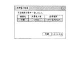
PC20のCPU201は、印刷管理サーバ30から各MFP10別の消費電力量の計算結果を受け取ると、例えば図19に示すように、各MFP10別の消費電力量の計算結果の一覧リストを含む操作画面を表示装置230に表示する。
After calculating the power consumption for each
When the
ユーザは、入力装置220(例えばマウス)により、操作画面上の印刷に使用したいMFP10の機器名を選択した後、「印刷」キーを押下(タッチ)する。
それによって、PC20のCPU201は、その選択された機器名のMFP10を示す情報を含む印刷依頼を印刷管理サーバ30へ送信する。
印刷管理サーバ30のCPU301は、PC20から印刷依頼を受信すると、その印刷要求によって指定されたMFP10を印刷使用機器として選択する。
The user selects the device name of the
Accordingly, the
When receiving the print request from the
このように、ユーザが各MFP10別の消費電力量を参考に印刷に使用したいMFP10を選択することにより、使用したくないMFP10(例えば通常の業務場所から離れた位置にあるMFP)の選択を回避することが可能になる。また、ユーザが印刷に使用したいMFP10の選択を最終的に判断することになるため、その分だけ印刷管理サーバ30のCPU301による処理負担が減ることになる。
In this way, by selecting the
あるいは、印刷管理サーバ30のCPU301は、各MFP10別の消費電力量を計算し、それらの比較によって印刷使用機器として選択したMFP10の消費電力量を計算結果(機器名等を含む)のみをPC20へ通知する。
PC20のCPU201は、印刷管理サーバ30から印刷使用機器として選択されたMFP10の消費電力量を計算結果を受け取ると、例えば図20に示すように、そのMFP10の消費電力量の計算結果を含む操作画面を表示装置230に表示する。
ユーザは、印刷使用機器として選択されたMFP10でOKであれば、入力装置220によって操作画面上の「印刷」キーを押下(タッチ)する。
それによって、PC20のCPU201は、印刷依頼を印刷管理サーバ30へ送信する。
印刷管理サーバ30のCPU301は、PC20から印刷依頼を受信すると、上記選択を確定する。
Alternatively, the
When the
If the
As a result, the
When the
このように、ユーザは、印刷使用機器として選択されたMFP10をPC20の表示画面を見ることによって認識することができるため、多数のMFP10が設置されたオフィス等においても、印刷結果が出力されたMFP10の設置場所にまっすぐ向かうことができるため、作業効率の向上につながる。
As described above, since the user can recognize the
以上、この発明を複数台のMFP(デジタル複合機)およびそれと印刷管理サーバ,PCとを通信可能に接続する画像形成システムに適用した実施形態について説明したが、この発明はそれらに限られるものではなく、複数台のデジタル複写機,プリンタ,ファクシミリ装置等の他の画像形成装置およびそれと印刷管理サーバ,PC(他の端末装置でもよい)とを通信可能に接続する画像処理システムにも適用可能である。
なお、それらの画像形成システムにおいて、印刷管理サーバとしての機能を複数台の画像形成装置のうちの少なくとも1台に備えることにより、印刷管理サーバを省くこともできる。この場合、印刷管理サーバとしての機能を有する画像形成装置が、他の複数の画像形成装置に対して第1〜第6実施例の各MFPに対する制御と同様の制御を行う。
The embodiment in which the present invention is applied to a plurality of MFPs (digital multifunction peripherals) and an image forming system in which the MFP, a print management server, and a PC are communicably connected has been described. It can also be applied to other image forming apparatuses such as a plurality of digital copiers, printers, facsimile machines, etc., and an image processing system for connecting the same to a print management server and a PC (or other terminal apparatus). is there.
In these image forming systems, the print management server can be omitted by providing a function as a print management server in at least one of the plurality of image forming apparatuses. In this case, an image forming apparatus having a function as a print management server performs the same control as the control for each MFP in the first to sixth embodiments with respect to other image forming apparatuses.
また、この発明によるプログラムは、印刷管理サーバのコンピュータ(CPU)に、この発明による機器選択手段,プロパティ取得手段,プロパティ登録手段,計算プログラム記憶手段,計算プログラム取得手段,モード移行抑止指示手段,モード移行抑止解除手段としての機能を実現させるためのプログラムであり、このようなプログラムをコンピュータに実行させることにより、上述したような効果を得ることができる。 A program according to the present invention is stored in a computer (CPU) of a print management server by a device selection unit, a property acquisition unit, a property registration unit, a calculation program storage unit, a calculation program acquisition unit, a mode transition inhibition instruction unit, a mode. This is a program for realizing the function as the migration inhibition releasing means, and the above-described effects can be obtained by causing the computer to execute such a program.
このようなプログラムは、はじめからコンピュータに備えるROMあるいはHDD等の記憶手段に格納しておいてもよいが、記録媒体であるCD−ROMあるいはフレキシブルディスク,SRAM,EEPROM,メモリカード等の不揮発性記録媒体(メモリ)に記録して提供することもできる。そのメモリに記録されたプログラムをコンピュータにインストールしてCPUに実行させるか、CPUにそのメモリからこのプログラムを読み出して実行させることにより、上述した各手順を実行させることができる。
さらに、ネットワークに接続され、プログラムを記録した記録媒体を備える外部機器あるいはプログラムを記憶手段に記憶した外部機器からダウンロードして実行させることも可能である。
Such a program may be stored in a storage means such as a ROM or HDD provided in the computer from the beginning, but a non-volatile recording such as a CD-ROM or flexible disk, SRAM, EEPROM, memory card or the like as a recording medium. It can also be recorded on a medium (memory) and provided. Each procedure described above can be executed by installing a program recorded in the memory in a computer and causing the CPU to execute the program, or causing the CPU to read and execute the program from the memory.
Furthermore, it is also possible to download and execute an external device that is connected to a network and includes a recording medium that records the program, or an external device that stores the program in the storage unit.
以上の説明から明らかなように、この発明によれば、管理装置(コンピュータ)が、画像形成システムを構成する複数台の画像形成装置の中から所要条件を確実に満たす画像形成装置を印刷に使用する機器として使用することができる。また、各画像形成装置別の消費電力量の計算結果と実際の消費電力量の不一致を回避することもできる。したがって、この発明を利用すれば、より便利な印刷管理を実行可能な管理装置を提供することができる。 As apparent from the above description, according to the present invention, the management device (computer), an image forming apparatus reliably satisfies the required condition from the plurality of image forming apparatuses constituting the image imaging system to the print It can be used as equipment to be used. Also, it is possible to avoid a mismatch between the calculation result of the power consumption for each image forming apparatus and the actual power consumption. Therefore, if this invention is used, a management apparatus capable of performing more convenient print management can be provided.
1:ネットワーク 10:MFP 11:コントローラ 14:エンジン
20:PC 30:印刷管理サーバ 101,201,301:CPU
102,202,302:ASIC 103,203,303:SDRAM
104,204,304:ROM 105,205,305:NVRAM
106,206,306:HDD 107:操作部
109,208,308:USB・I/F
110,209,309:IEEE1394・I/F
111,210,310:MAC・I/F 121:通信処理部
122:時間計測部 123:電力制御部 124:記憶部
125:メイン制御部 200:装置本体 220:入力装置 230:表示装置
1: Network 10: MFP 11: Controller 14: Engine 20: PC 30:
102, 202, 302:
104, 204, 304:
106, 206, 306: HDD 107:
110, 209, 309: IEEE1394 / I / F
111, 210, 310: MAC • I / F 121: Communication processing unit 122: Time measurement unit 123: Power control unit 124: Storage unit 125: Main control unit 200: Device main body 220: Input device 230: Display device
Claims (22)
前記端末装置から前記印刷データおよび所要条件を含む印刷依頼を受け、該所要条件が印刷条件の場合に、該印刷条件および前記各画像形成装置の現時点の電力モードに基づいて該各画像形成装置で前記印刷データの印刷によって消費される該各画像形成装置別の消費電力量をそれぞれ計算する消費電力量計算手段を有し、該手段による各計算結果に基づいて該各画像形成装置のいずれかを前記印刷に使用する機器として選択する機器選択手段と、
前記消費電力量計算手段による各画像形成装置別の計算の開始前に、その計算対象の画像形成装置に対して電力モード移行の抑止を指示するモード移行抑止指示手段と、
前記消費電力量計算手段による各画像形成装置別の計算結果に基づき前記機器選択手段により選択された画像形成装置に前記印刷依頼に係る印刷指示が送信された後、その計算対象の画像形成装置に対して電力モード移行の抑止解除を指示するモード移行抑止解除手段とを設け、
前記機器選択手段は、前記所要条件が印刷条件と印刷スピードよりも省エネルギーを優先する機器選択条件とからなる場合に、前記消費電力量計算手段による各計算結果から最も消費電力量の少ない画像形成装置を前記印刷に使用する機器として選択することを特徴とする管理装置。 A terminal device that generates print data, and a plurality of image forming devices that print the print data from the terminal device on a print medium as a visible image are connected via a communication line, and the terminal device A management apparatus that selectively transmits print data to each of the image forming apparatuses to perform the printing;
In response to a print request including the print data and necessary conditions from the terminal device, and when the necessary conditions are printing conditions, each image forming apparatus is based on the printing conditions and the current power mode of each image forming apparatus. Power consumption calculation means for calculating the power consumption for each image forming apparatus consumed by printing the print data, respectively, and any one of the image forming apparatuses is determined based on the calculation result by the means. Device selection means for selecting as a device to be used for the printing;
Before starting the calculation for each image forming apparatus by the power consumption calculation means, mode transition inhibition instruction means for instructing the image forming apparatus to be calculated to inhibit the power mode transition;
After a print instruction related to the print request is transmitted to the image forming apparatus selected by the device selection unit based on the calculation result for each image forming apparatus by the power consumption calculating unit, the calculation target image forming apparatus And a mode transition suppression release means for instructing the power mode transition suppression cancellation ,
The device selecting means is an image forming apparatus that consumes the least amount of power from the calculation results of the power consumption calculating means when the required conditions are printing conditions and device selection conditions that prioritize energy saving over printing speed. Is selected as a device to be used for the printing .
前記各画像形成装置からそれぞれ該画像形成装置の現時点の電力モードを示すプロパティを取得するプロパティ取得手段を設けたことを特徴とする管理装置。 In the management apparatus according to claim 1 Symbol placement,
A management apparatus comprising a property acquisition unit configured to acquire a property indicating a current power mode of the image forming apparatus from each of the image forming apparatuses.
前記各画像形成装置の現時点の電力モードを示すプロパティを登録するプロパティ登録手段を設けたことを特徴とする管理装置。 In the management apparatus according to claim 1 Symbol placement,
A management apparatus comprising property registration means for registering a property indicating a current power mode of each image forming apparatus.
前記プロパティ登録手段は、前記各画像形成装置からそれぞれ通知されてくる該各画像形成装置の前記プロパティを登録することを特徴とする管理装置。 The management device according to claim 3 ,
The property registration unit registers the property of each image forming apparatus notified from each of the image forming apparatuses.
前記プロパティ登録手段は、外部から入力される前記各画像形成装置別の前記プロパティを登録することを特徴とする管理装置。 The management device according to claim 3 ,
The property registration unit registers the property for each of the image forming apparatuses input from the outside.
前記各画像形成装置別の消費電力量を計算するための該各画像形成装置別の計算プログラムをそれぞれ記憶する計算プログラム記憶手段を設け、
前記消費電力量計算手段は、前記各画像形成装置別の計算プログラムに従って前記各画像形成装置別の消費電力量を計算することを特徴とする管理装置。 In the management device according to any one of claims 1 to 5 ,
A calculation program storage means for storing a calculation program for each image forming apparatus for calculating power consumption for each image forming apparatus;
The management apparatus according to claim 1, wherein the power consumption calculating means calculates a power consumption for each image forming apparatus in accordance with a calculation program for each image forming apparatus.
前記端末装置から前記各画像形成装置別の前記計算プログラムを取得する計算プログラム取得手段を設けたことを特徴とする管理装置。 The management device according to claim 6 ,
A management apparatus comprising calculation program acquisition means for acquiring the calculation program for each image forming apparatus from the terminal device.
前記各画像形成装置からそれぞれ前記計算プログラムを取得する計算プログラム取得手段を設けたことを特徴とする管理装置。 The management device according to claim 6 ,
A management apparatus comprising a calculation program acquisition means for acquiring the calculation program from each of the image forming apparatuses.
前記管理装置のプロパティ取得手段は、前記端末装置から前記印刷依頼を受けた場合に、前記各画像形成装置に対して該各画像形成装置の前記プロパティを要求する手段を有し、
前記各画像形成装置はそれぞれ、前記管理装置から前記プロパティの要求を受けた場合に、自己の前記プロパティを前記管理装置へ通知するプロパティ通知手段と、前記管理装置から前記電力モード移行の抑止が指示されてから該抑止の解除が指示されるまで、自己の電力モードの移行を抑止するモード移行抑止手段とを設けたことを特徴とする画像形成システム。 The image forming system capable of connecting the management device according to claim 2, the terminal device, and each image forming device via the communication line,
The property acquisition unit of the management apparatus includes a unit that requests the property of each image forming apparatus from the image forming apparatus when the print request is received from the terminal apparatus.
Each of the image forming apparatuses, when receiving a request for the property from the management apparatus, property notification means for notifying the management apparatus of its own property, and the management apparatus instructing suppression of the power mode transition An image forming system, comprising: a mode transition suppression unit that suppresses transition of its own power mode until the cancellation of the suppression is instructed.
前記各画像形成装置はそれぞれ、所定のタイミングで自己の前記プロパティを前記管理装置へ通知するプロパティ通知手段と、前記管理装置から前記電力モード移行の抑止が指示されてから該抑止の解除が指示されるまで、自己の電力モードの移行を抑止するモード移行抑止手段とを設けたことを特徴とする画像形成システム。 The image forming system capable of connecting the management device according to claim 4, the terminal device, and each image forming device via the communication line,
Each of the image forming apparatuses is instructed to notify the management apparatus of its own property at a predetermined timing, and to cancel the suppression after the management apparatus is instructed to suppress the power mode transition. An image forming system, comprising: a mode transition inhibiting unit that inhibits transition of its own power mode until
前記各画像形成装置のプロパティ通知手段はそれぞれ、当該画像形成装置の起動時に該画像形成装置の前記プロパティを前記管理装置へ通知することを特徴とする画像形成システム。 In claim 1 0, wherein the image forming system,
The property notification unit of each image forming apparatus notifies the management apparatus of the property of the image forming apparatus when the image forming apparatus is activated.
前記管理装置の計算プログラム取得手段は、前記端末装置から前記印刷依頼を受けた場合に、前記各画像形成装置に対して前記計算プログラムを要求する手段を有し、
前記各画像形成装置はそれぞれ、前記管理装置から前記計算プログラムの要求を受けた場合に、対応する前記計算プログラムを前記管理装置へ通知する計算プログラム通知手段と、前記管理装置から前記電力モード移行の抑止が指示されてから該抑止の解除が指示されるまで、自己の電力モードの移行を抑止するモード移行抑止手段とを設けたことを特徴とする画像形成システム。 The image forming system capable of connecting the management device according to claim 8, the terminal device, and the image forming devices via the communication line,
The calculation program acquisition means of the management device has means for requesting the calculation program to each of the image forming apparatuses when receiving the print request from the terminal device,
Each of the image forming apparatuses, when receiving a request for the calculation program from the management apparatus, a calculation program notification means for notifying the management apparatus of the corresponding calculation program; An image forming system, comprising: a mode transition inhibiting unit that inhibits transition of its own power mode from when the inhibition is instructed until the cancellation of the inhibition is instructed.
前記端末装置から前記印刷データおよび所要条件を含む印刷依頼を受け、該所要条件が印刷条件の場合に、該印刷条件および前記各画像形成装置の現時点の電力モードに基づいて該各画像形成装置で前記印刷データの印刷によって消費される該各画像形成装置別の消費電力量をそれぞれ計算し、その各計算結果に基づいて前記各画像形成装置のいずれかを前記印刷に使用する機器として選択する機器選択工程と、前記各画像形成装置別の消費電力量の計算の開始前に、その計算対象の画像形成装置に対して電力モード移行の抑止を指示するモード移行抑止指示工程と、前記各画像形成装置別の消費電力量の計算結果に基づき前記機器選択手段により選択された画像形成装置に前記印刷依頼に係る印刷指示が送信された後、その計算対象の画像形成装置に対して電力モード移行の抑止解除を指示するモード移行抑止解除工程とを有し、
前記機器選択工程は、前記所要条件が印刷条件と印刷スピードよりも省エネルギーを優先する機器選択条件とからなる場合に、前記各計算結果から最も消費電力量の少ない画像形成装置を前記印刷に使用する機器として選択することを特徴とする制御方法。 A terminal device that generates print data, and a plurality of image forming devices that print the print data from the terminal device on a print medium as a visible image are connected via a communication line, and the terminal device A control method in a management apparatus that selectively transmits print data to each of the image forming apparatuses to perform the printing,
In response to a print request including the print data and necessary conditions from the terminal device, and when the necessary conditions are printing conditions, each image forming apparatus is based on the printing conditions and the current power mode of each image forming apparatus. A device that calculates power consumption for each image forming apparatus consumed by printing the print data, and selects one of the image forming apparatuses as a device to be used for the printing based on each calculation result A selection step, a mode transition inhibition instruction step for instructing the image forming apparatus that is the calculation target to inhibit power mode transition before starting calculation of the power consumption amount for each of the image forming apparatuses, and each image formation After the print instruction related to the print request is transmitted to the image forming apparatus selected by the device selection unit based on the calculation result of the power consumption for each apparatus, the calculation target image Possess a mode shift inhibit release step of indicating the inhibit release of power mode switching with respect to forming apparatus,
In the device selection step, when the required condition includes a printing condition and a device selection condition that prioritizes energy saving over the printing speed, an image forming apparatus that consumes the least amount of power is used for the printing from the calculation results. A control method characterized by selecting as a device .
前記各画像形成装置からそれぞれ該画像形成装置の現時点の電力モードを示すプロパティを取得することを特徴とする制御方法。 The control method in the management apparatus according to claim 1 3 Symbol placement,
A control method for acquiring a property indicating a current power mode of the image forming apparatus from each of the image forming apparatuses.
前記各画像形成装置の現時点の電力モードを示すプロパティを登録することを特徴とする制御方法。 The control method in the management apparatus according to claim 1 3 Symbol placement,
A control method for registering a property indicating a current power mode of each image forming apparatus.
前記各画像形成装置からそれぞれ通知されてくる該各画像形成装置の前記プロパティを登録することを特徴とする制御方法。 In the control method in the management device according to claim 15 ,
A control method comprising: registering the property of each image forming apparatus notified from each image forming apparatus.
外部から入力される前記各画像形成装置別の前記プロパティを登録することを特徴とする制御方法。 In the control method in the management device according to claim 15 ,
A control method for registering the property for each image forming apparatus input from the outside.
予め前記各画像形成装置別の消費電力量を計算するための該各画像形成装置別の計算プログラムをそれぞれ記憶しておき、その各画像形成装置別の計算プログラムに従って前記各画像形成装置別の消費電力量を計算することを特徴とする制御方法。 The control method in the management apparatus according to any one of claims 1 3 to 17,
A calculation program for each image forming apparatus for calculating the power consumption for each image forming apparatus is stored in advance, and the consumption for each image forming apparatus is determined according to the calculation program for each image forming apparatus. A control method characterized by calculating an electric energy.
前記端末装置から前記各画像形成装置別の前記計算プログラムを取得することを特徴とする制御方法。 In the control method in the management device according to claim 18 ,
A control method for acquiring the calculation program for each image forming apparatus from the terminal device.
前記各画像形成装置からそれぞれ前記計算プログラムを取得することを特徴とする制御方法。 In the control method in the management device according to claim 18 ,
A control method comprising: obtaining the calculation program from each of the image forming apparatuses.
前記端末装置から前記印刷データおよび所要条件を含む印刷依頼を受け、該所要条件が印刷条件の場合に、該印刷条件および前記各画像形成装置の現時点の電力モードに基づいて該各画像形成装置で前記印刷データの印刷によって消費される該各画像形成装置別の消費電力量をそれぞれ計算する消費電力量計算機能を有し、該機能による各計算結果に基づいて該各画像形成装置のいずれかを前記印刷に使用する機器として選択する機器選択機能と、
前記消費電力量計算機能による各画像形成装置別の計算の開始前に、その計算対象の画像形成装置に対して電力モード移行の抑止を指示するモード移行抑止指示機能と、
前記消費電力量計算手段による各画像形成装置別の計算結果に基づき前記機器選択手段により選択された画像形成装置に前記印刷依頼に係る印刷指示が送信された後、その計算対象の画像形成装置に対して電力モード移行の抑止解除を指示するモード移行抑止解除機能とを実現させるためのプログラムであり、
前記機器選択機能は、前記所要条件が印刷条件と印刷スピードよりも省エネルギーを優先する機器選択条件とからなる場合に、前記消費電力量計算機能による各計算結果から最も消費電力量の少ない画像形成装置を前記印刷に使用する機器として選択することを特徴とするプログラム。 A terminal device that generates print data, and a plurality of image forming devices that print the print data from the terminal device on a print medium as a visible image are connected via a communication line, and the terminal device A computer of a management apparatus that selectively transmits print data to each of the image forming apparatuses to perform the printing,
In response to a print request including the print data and necessary conditions from the terminal device, and when the necessary conditions are printing conditions, each image forming apparatus is based on the printing conditions and the current power mode of each image forming apparatus. A power consumption amount calculating function for calculating a power consumption amount for each of the image forming apparatuses consumed by printing the print data, and selecting one of the image forming apparatuses based on each calculation result by the function; A device selection function for selecting as a device to be used for the printing;
Before starting calculation for each image forming apparatus by the power consumption calculation function, a mode transition suppression instruction function for instructing suppression of power mode transition to the target image forming apparatus;
After a print instruction related to the print request is transmitted to the image forming apparatus selected by the device selection unit based on the calculation result for each image forming apparatus by the power consumption calculating unit, the calculation target image forming apparatus It is a program for realizing a mode transition suppression release function that instructs the cancellation of power mode transition suppression ,
The device selection function includes an image forming apparatus that consumes the least amount of power from the calculation results of the power consumption calculation function when the required conditions include a printing condition and a device selection condition that prioritizes energy saving over printing speed. Is selected as a device to be used for the printing .
Priority Applications (1)
| Application Number | Priority Date | Filing Date | Title |
|---|---|---|---|
| JP2004332301A JP4537833B2 (en) | 2004-11-16 | 2004-11-16 | Image forming system, image forming apparatus, control method, program, and recording medium |
Applications Claiming Priority (1)
| Application Number | Priority Date | Filing Date | Title |
|---|---|---|---|
| JP2004332301A JP4537833B2 (en) | 2004-11-16 | 2004-11-16 | Image forming system, image forming apparatus, control method, program, and recording medium |
Publications (3)
| Publication Number | Publication Date |
|---|---|
| JP2006145630A JP2006145630A (en) | 2006-06-08 |
| JP2006145630A5 JP2006145630A5 (en) | 2007-05-17 |
| JP4537833B2 true JP4537833B2 (en) | 2010-09-08 |
Family
ID=36625444
Family Applications (1)
| Application Number | Title | Priority Date | Filing Date |
|---|---|---|---|
| JP2004332301A Expired - Fee Related JP4537833B2 (en) | 2004-11-16 | 2004-11-16 | Image forming system, image forming apparatus, control method, program, and recording medium |
Country Status (1)
| Country | Link |
|---|---|
| JP (1) | JP4537833B2 (en) |
Families Citing this family (7)
| Publication number | Priority date | Publication date | Assignee | Title |
|---|---|---|---|---|
| JP4415993B2 (en) | 2007-01-29 | 2010-02-17 | コニカミノルタビジネステクノロジーズ株式会社 | Image processing apparatus, job processing method, and program |
| JP4245055B2 (en) | 2007-01-29 | 2009-03-25 | コニカミノルタビジネステクノロジーズ株式会社 | Image processing system, image processing apparatus, job processing method, and program |
| JP4673907B2 (en) * | 2008-06-27 | 2011-04-20 | 株式会社沖データ | Image forming apparatus |
| JP5602585B2 (en) * | 2010-10-29 | 2014-10-08 | キヤノン株式会社 | Power consumption control system and power consumption control method |
| JP5457424B2 (en) * | 2011-11-24 | 2014-04-02 | シャープ株式会社 | Image forming system |
| JP5679029B2 (en) * | 2013-10-18 | 2015-03-04 | 株式会社リコー | Power consumption deriving device, power consumption deriving method, program, and power consumption deriving system |
| JP2021022000A (en) * | 2019-07-24 | 2021-02-18 | 京セラドキュメントソリューションズ株式会社 | Print system |
Citations (3)
| Publication number | Priority date | Publication date | Assignee | Title |
|---|---|---|---|---|
| JP2000187579A (en) * | 1998-12-22 | 2000-07-04 | Canon Inc | Printing system, printer, printing control method and recording medium |
| JP2002297715A (en) * | 2001-03-30 | 2002-10-11 | Minolta Co Ltd | Processor and method for information processing, system and processor for image processing, monitor, monitoring method, method of displaying electric power consumption, program, and recording medium |
| JP2002318674A (en) * | 2001-04-20 | 2002-10-31 | Ricoh Co Ltd | Printer system |
-
2004
- 2004-11-16 JP JP2004332301A patent/JP4537833B2/en not_active Expired - Fee Related
Patent Citations (3)
| Publication number | Priority date | Publication date | Assignee | Title |
|---|---|---|---|---|
| JP2000187579A (en) * | 1998-12-22 | 2000-07-04 | Canon Inc | Printing system, printer, printing control method and recording medium |
| JP2002297715A (en) * | 2001-03-30 | 2002-10-11 | Minolta Co Ltd | Processor and method for information processing, system and processor for image processing, monitor, monitoring method, method of displaying electric power consumption, program, and recording medium |
| JP2002318674A (en) * | 2001-04-20 | 2002-10-31 | Ricoh Co Ltd | Printer system |
Also Published As
| Publication number | Publication date |
|---|---|
| JP2006145630A (en) | 2006-06-08 |
Similar Documents
| Publication | Publication Date | Title |
|---|---|---|
| JP4820432B2 (en) | Printer driver, recording medium, information processing apparatus, printing system, and printer driver setting method | |
| JP6289085B2 (en) | Information processing apparatus, information processing method, and program | |
| JP4407737B2 (en) | Image forming apparatus and program | |
| JP2007267362A (en) | Printing device, printing method and program for printing | |
| US9377981B2 (en) | Image forming system that sends schedule information of image forming apparatus over network | |
| JP5121261B2 (en) | Image processing apparatus, image processing apparatus control method, and control program | |
| JP4848025B2 (en) | Image forming apparatus and image forming system | |
| JP2004355197A (en) | Network print system | |
| JP2005110278A (en) | Document processing method and document processing system using data storage | |
| JP2017140708A (en) | Communication control method, program and printing device | |
| JP4537833B2 (en) | Image forming system, image forming apparatus, control method, program, and recording medium | |
| JP2007210237A (en) | Image-forming apparatus | |
| JP4414943B2 (en) | Image formation control method and image formation control program | |
| JP2011232889A (en) | Computer program and terminal device | |
| JP2011177966A (en) | Image forming apparatus, image forming system, and method of controlling the image forming apparatus | |
| EP2306368A2 (en) | Image processing device having a plurality of control units | |
| JP2017038171A (en) | Image reading device and control method for image reading device | |
| JP2011146016A (en) | Printing system, printer driver and copier | |
| JP2006146360A (en) | Image formation system and its image formation apparatus, control method, program and recording medium | |
| JP5686063B2 (en) | Network system, image forming apparatus, and program | |
| JP7016667B2 (en) | Image processing device and control method and program of the image processing device | |
| US8848235B2 (en) | Systems and methods for displaying a print preview | |
| JP2008244912A (en) | Copying machine and method of copy processing | |
| JP7263575B2 (en) | JOB EXECUTION DEVICE, CONTROL METHOD AND PROGRAM OF JOB EXECUTION DEVICE | |
| JP2004272390A (en) | Printing system, data processor, printer, and computer program |
Legal Events
| Date | Code | Title | Description |
|---|---|---|---|
| A521 | Request for written amendment filed |
Free format text: JAPANESE INTERMEDIATE CODE: A523 Effective date: 20070326 |
|
| A621 | Written request for application examination |
Free format text: JAPANESE INTERMEDIATE CODE: A621 Effective date: 20070326 |
|
| A131 | Notification of reasons for refusal |
Free format text: JAPANESE INTERMEDIATE CODE: A131 Effective date: 20090714 |
|
| A521 | Request for written amendment filed |
Free format text: JAPANESE INTERMEDIATE CODE: A523 Effective date: 20090911 |
|
| A131 | Notification of reasons for refusal |
Free format text: JAPANESE INTERMEDIATE CODE: A131 Effective date: 20091104 |
|
| A521 | Request for written amendment filed |
Free format text: JAPANESE INTERMEDIATE CODE: A523 Effective date: 20091225 |
|
| A131 | Notification of reasons for refusal |
Free format text: JAPANESE INTERMEDIATE CODE: A131 Effective date: 20100406 |
|
| A521 | Request for written amendment filed |
Free format text: JAPANESE INTERMEDIATE CODE: A523 Effective date: 20100524 |
|
| RD02 | Notification of acceptance of power of attorney |
Free format text: JAPANESE INTERMEDIATE CODE: A7422 Effective date: 20100524 |
|
| TRDD | Decision of grant or rejection written | ||
| A01 | Written decision to grant a patent or to grant a registration (utility model) |
Free format text: JAPANESE INTERMEDIATE CODE: A01 Effective date: 20100615 |
|
| A01 | Written decision to grant a patent or to grant a registration (utility model) |
Free format text: JAPANESE INTERMEDIATE CODE: A01 |
|
| A61 | First payment of annual fees (during grant procedure) |
Free format text: JAPANESE INTERMEDIATE CODE: A61 Effective date: 20100618 |
|
| FPAY | Renewal fee payment (event date is renewal date of database) |
Free format text: PAYMENT UNTIL: 20130625 Year of fee payment: 3 |
|
| R150 | Certificate of patent or registration of utility model |
Free format text: JAPANESE INTERMEDIATE CODE: R150 |
|
| LAPS | Cancellation because of no payment of annual fees |